

Page 1
GE’s 2015 27” Top Load Washer
HTW200ASKWW
MTW200AMKWW
GTW220ACKWW
HTW240ASKWW
GTW330ASKWW
GTW460ASJWW
GTW485ASJWW
GE Appliances
GTW485ASJWS
GTW490ACJWW
GTW490ACJWS
GTW680BSJWS
1
11/16/2015
Page 2

IMPORTANT SAFETY NOTICE
The information in this presentation is intended for use by individuals
possessing adequate backgrounds of electrical, electronic, &
mechanical experience. Any attempt to repair a major appliance may
result in personal injury & property damage. The manufacturer or seller
cannot be responsible for the interpretation of this information, nor can it
assume any liability in connection with its use.
WARNING
To avoid personal injury, disconnect power before servicing
this product. If electrical power is required for diagnosis or
test purposes, disconnect the power immediately after
performing the necessary checks.
RECONNECT ALL GROUNDING DEVICES
If grounding wires, screws, straps, clips, nuts, or washers used to
complete a path to ground are removed for service, they must be
returned to their original position & properly fastened.
Page 3

Although GE Factory Service Employees are required to use the personal
protection equipment (PPE) listed below, it is recommended for GE
authorized servicers to use them as well for your own protection.
Dyneema® Cut
Resistant Glove
Cut Resistant Sleeve(s)
Steel Toe Work
Boot
Electrically Rated Glove
and Dyneema® Cut
Resistant Glove Keeper
Brazing Glasses
Plano Type Safety
Glasses
Prescription
Safety Glasses
Safety Glasses
must be
ANSI Z87.1-2003
compliant
Page 4

Prior to disassembly of the Washer to access components, GE Factory Service
technicians are REQUIRED to follow the Lockout / Tagout (LOTO) 6 Step Process
Step 1
Plan and Prepare
Step 2
Shut down the appliance
Step 3
Isolate the appliance
Step 4
Apply LOTO device & Lock
Step 5
Control (discharge) stored
energy
Step 6
“Try It” Verify that the
appliance is locked out
GE Appliances
Louisville, KY 40225
Page 5

Some Features & Benefits
GTW460 Models
Deep Fill: Adds more water for larger
loads.
Dual-Action Agitator: Provide gentle,
dual-wash action.
Deep Rinse: Removes any leftover soap
residue.
Auto Soak: Loosens stains by soaking
up to 2 hours.
Speed Wash: Delivers ready-to-go
results within minutes.
Load Size: Automatically measures load
size, and adjusts settings and water
levels accordingly. Settings are
customizable, so you always get the
wash you want.
GTW680 Models
Sanitize with Oxi: Remove 99.9 % of
bacteria with a dedicated cycle that
uses an Oxi additive to boost your
detergents cleaning power while
keeping fabric looking their best.
Stain Removal Guide: Assist removing
tough stains with preprogrammed
settings that modify your cycle to treat
the four most common stains.
Warm Rinse: Just what the consumer
ordered. The option to select between
a warm or cold rinse.
Deep Fill: Adds more water for larger
loads.
Deep Rinse: Removes any leftover soap
residue.
Auto Soak: Loosens stains by soaking
up to 2 hours.
5
11/16/2015
Page 6

Nomenclature
Brand
Configuration
Platform
Series 1, 2, 3
Fuel Type
Partner Type
Product Type
Engineering #
Year
G T W 6 8 0 B S J 0 W S
Brand
G-GE
H-Hot Point
M-Moffatt
Configuration
F-Front Load
T-Top Load - Rear control
N-Top Load - Front control
U-Unitized
Platform
W-Washer
D-Vented Dryer- Std
V-Vented Dryer- Long
C-Condenser Dryer
H-Heat Pump
Z-Flat Back Dryer- Long
X-Flat Back Dryer- Std
Series 1 1-9
Series 2 1-9
4 = 24” unitized
7 = 27” unitized
Series 3 1-9 Washer only
Fuel Type Dryer
E Electric
G Gas
P Propane
Color
Partner Type
P-Premium Cost (color)
H-Home Depot
L-Lowes
S-Standard
C-Contract (Hoses)
M-Mabe
Product Type
R Riser
A 2” Cover Top Load
B 4” Cover Top Load
S Standard/Stationary
P Portable
6
11/16/2015
Page 7
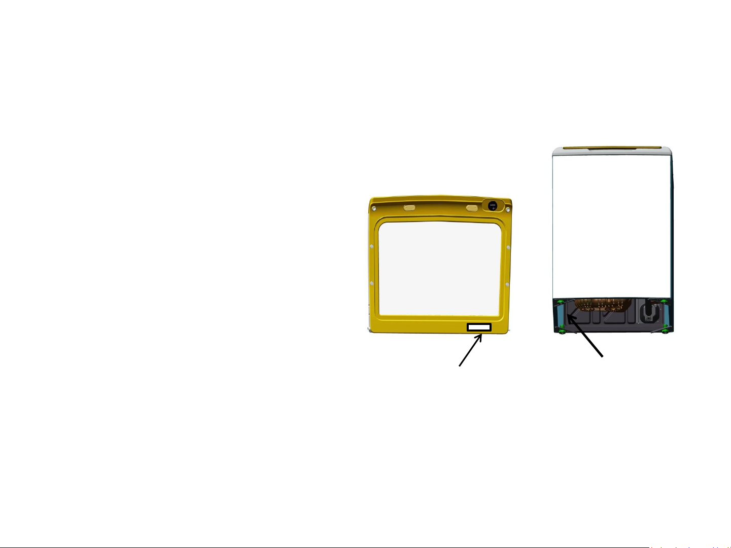
Nomenclature and Mini (MAXI) Manual Location
Serial Number
The nomenclature breaks down and explains what the letters and numbers
mean in the model number. The first two characters of the serial number
identify the month and year of manufacture. Example: LF123456S = June, 2015
A- JAN
D- FEB
F- MAR
G- APR
H- MAY
L- JUN
M- JUL
R- AUG
S- SEP
T- OCT
V- NOV
2024- Z
2023- V
2022- T
2021- S
2020- R
2019- M
2018- L
2017- H
2016- G
2015- F
2014- D
The mini (maxi) manual
Z- DEC
2013- A
Model ID Tag Location.
location. Tilt washer
back to retrieve.
The letter designating the year repeats every 12 years.
The Model Serial ID Tag is located on the bottom edge of the lid.
The Mini Manual is in a storage bag on the inside bottom left side of the outer cabinet.
7
11/16/2015
Page 8

Water Levels
Approximate Minimum Water Levels
Impeller – 7 Gallons or 3 in. depth
from the bottom of the basket.
Agitator – 9 Gallons or 3-3/4 in.
depth from the bottom of the basket.
Approximate Maximum Water Levels
Impeller – 26 Gallons or 13-1/2 in.
depth from the bottom of the basket.
Press and hold for 3 seconds “Deep
Fill” to achieve.
Impeller “Bulky” setting water level is
25 gallons or 12-3/4 in. depth from
the bottom of the basket.
Agitator – 26 Gallons or 12-1/2 in.
depth from the bottom of the basket.
Set to super.
Tests are completed with an empty basket.
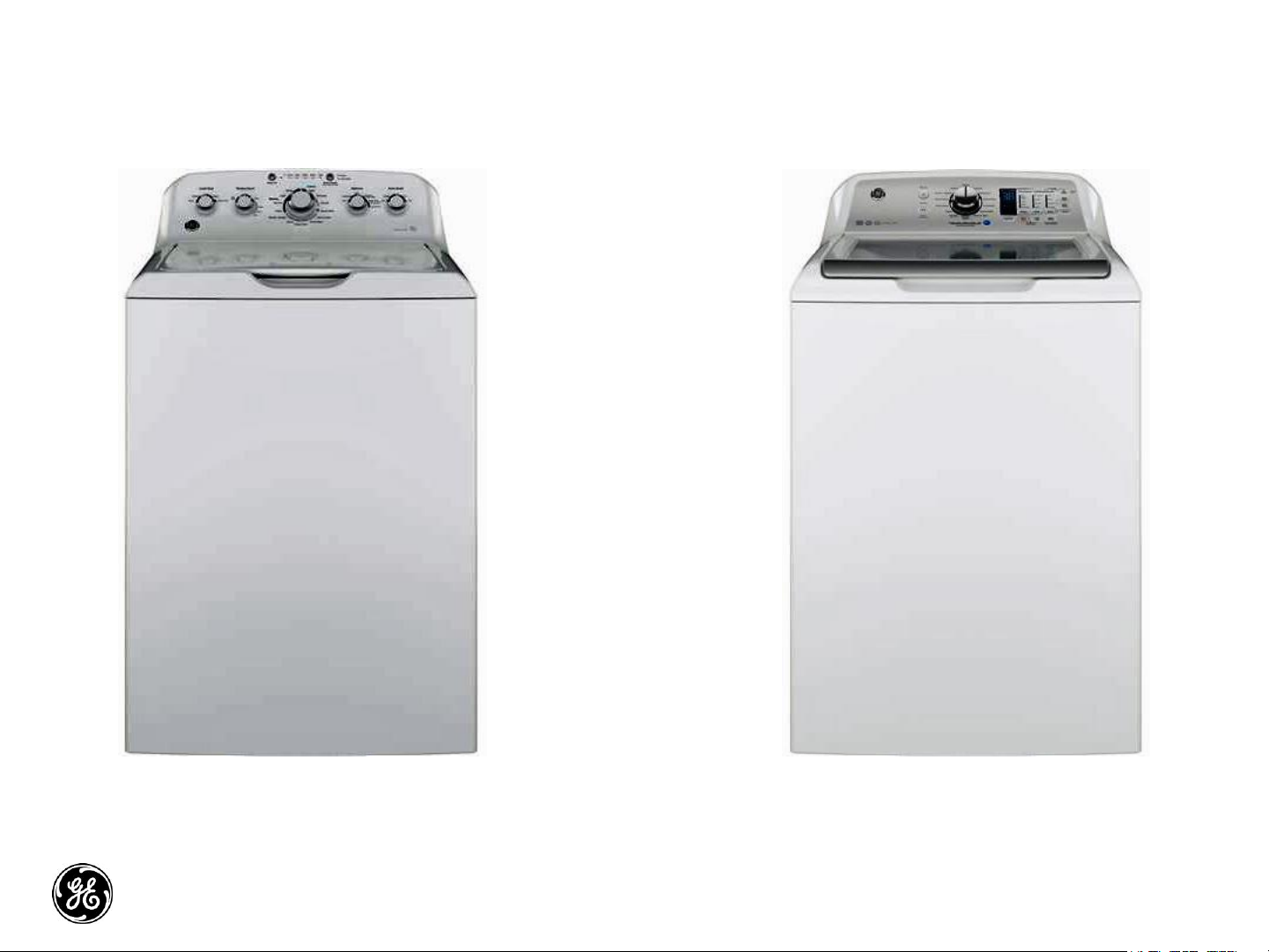
Page 9
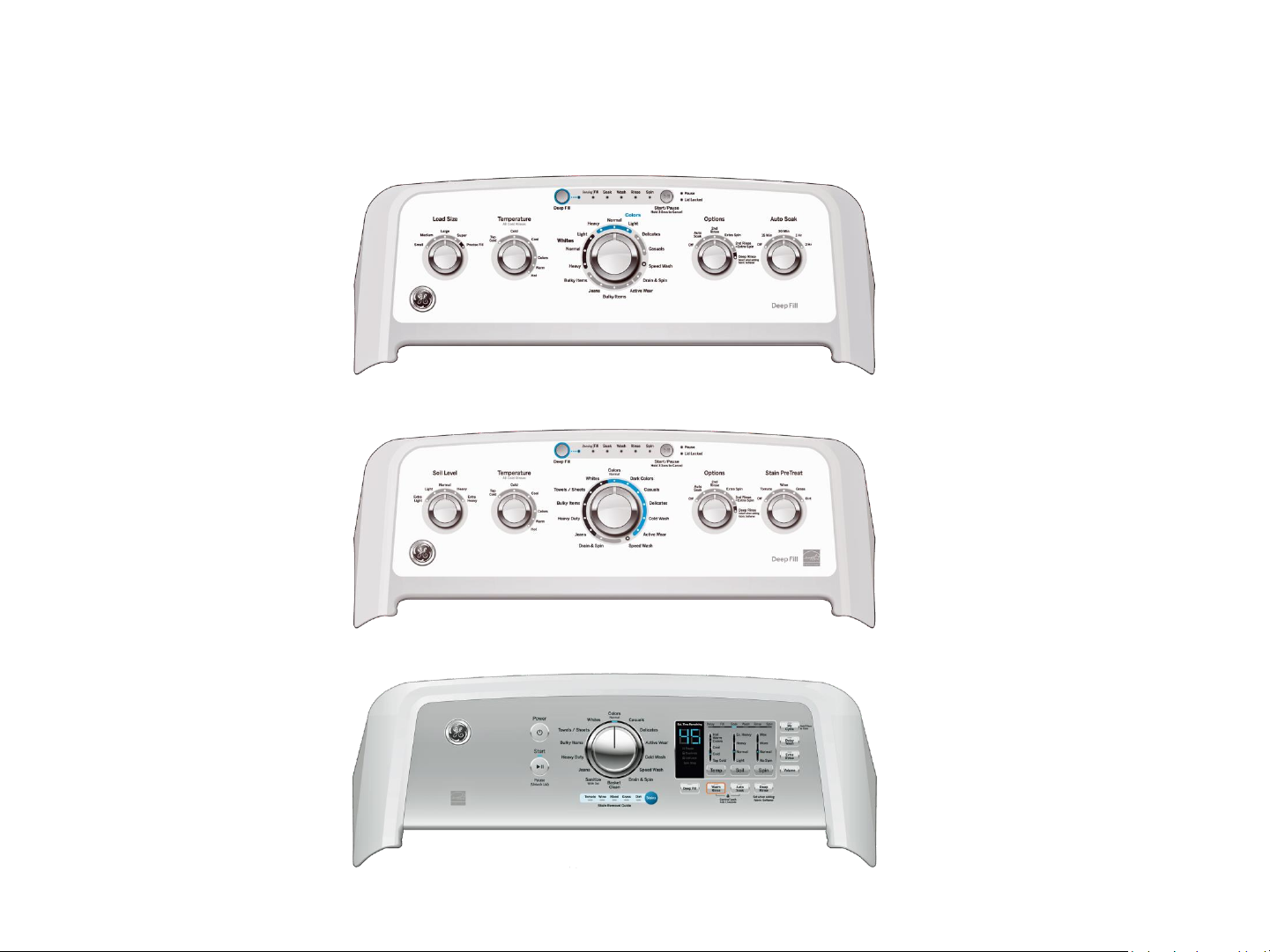
Model Graphics
GTW460
GTW485 GTW490
GTW680
9
11/16/2015
Page 10
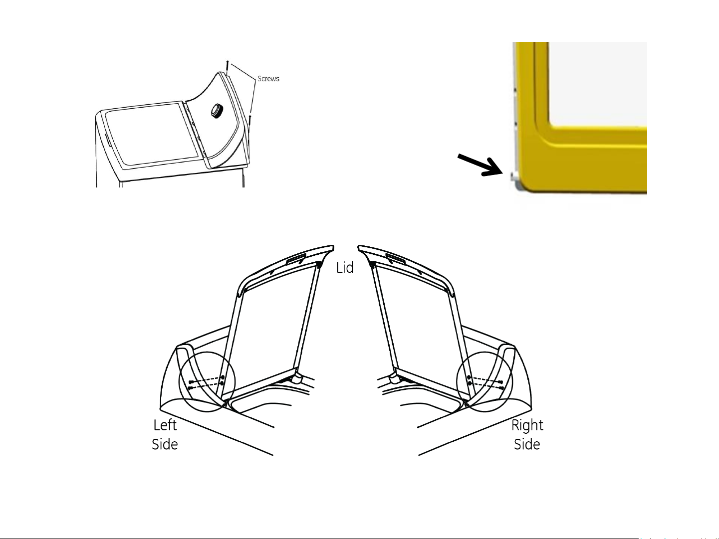
Lid Assembly Removal
Hinge Pin
Cover
Remove the two 1/4 in. hex
head screws that secure
the control panel assembly
to the top cover.
Remove the four Philips head screws (two on each side) and lift lid up to remove.
Slide the control panel
assembly toward the rear
of the washer to expose the
hinge pin cover.
10
11/16/2015
Page 11
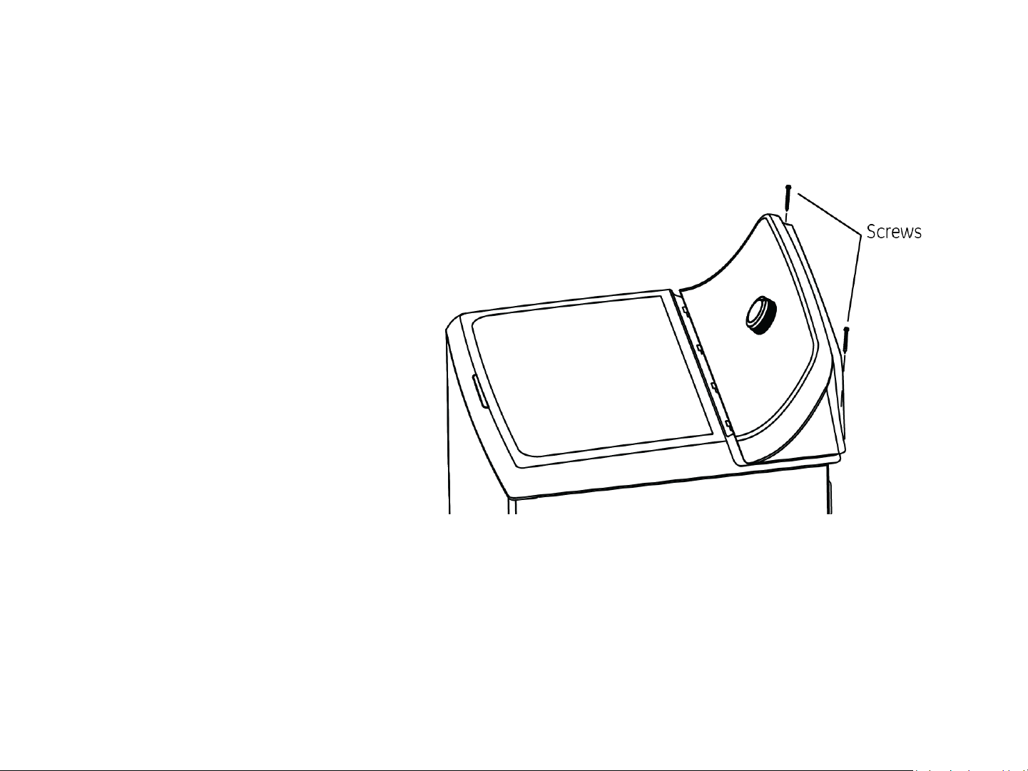
Control Panel Assembly Removal
To remove the control
panel assembly:
Remove two 1/4 in. hex
head screws from the rear
corners of the control
panel.
11
11/16/2015
Page 12
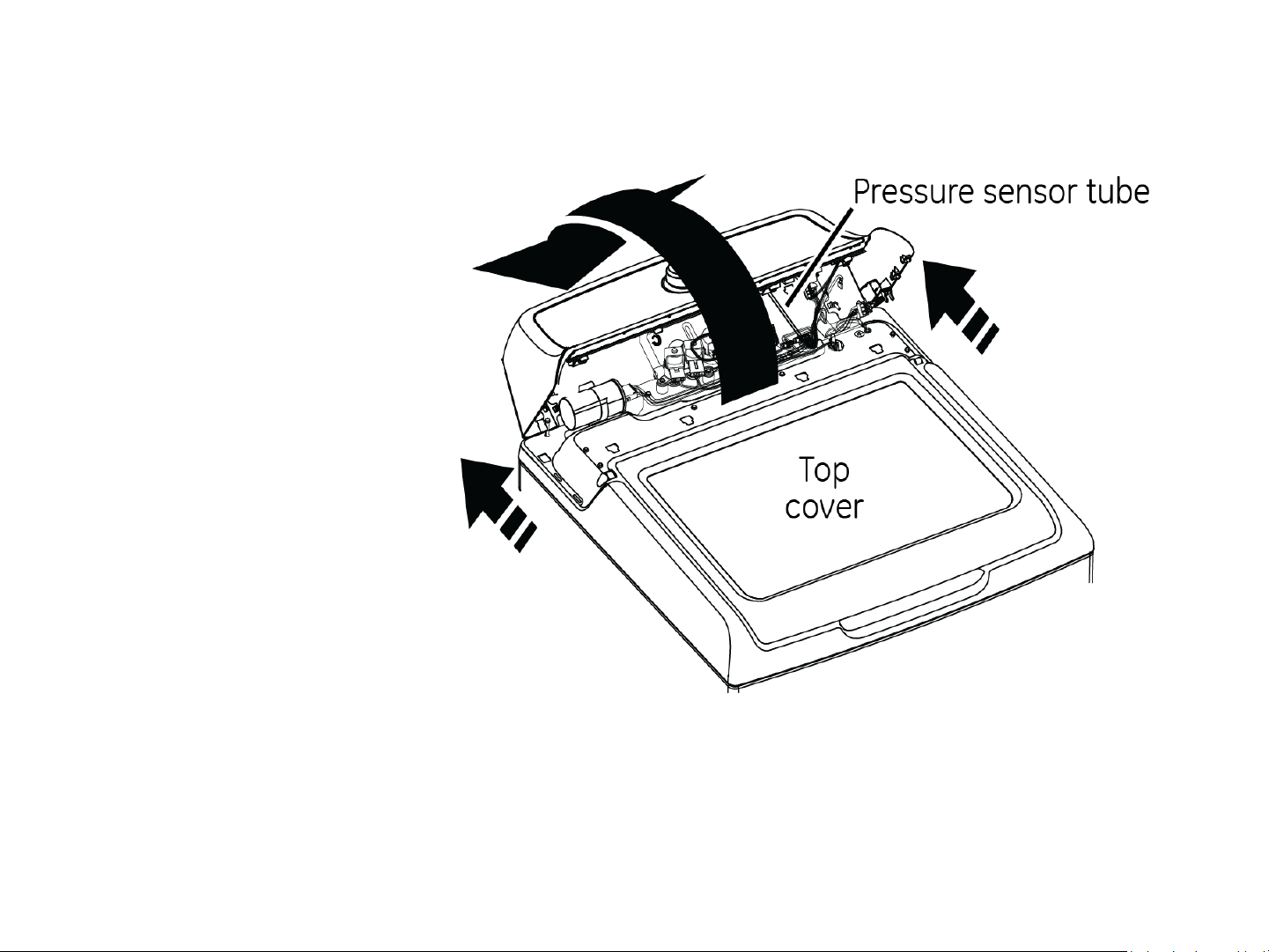
Control Panel Assembly Removal
Grasp the control panel
sides and push toward
the back of the washer
to disengage it from the
top cover.
Roll the control panel
toward the rear so the
pressure tube can be
seen and disconnected
from the control board.
IMPORTANT: To disengage the pressure tube from the control board, grasp the tube where it
connects to the pressure sensor on the board. Twist the tube while pulling it off the sensor.
12
11/16/2015
Page 13

Control Panel Assembly Removal
Roll the control panel
forward to lay on its face
and remove four 1/4 in.
hex screws securing the
rear panel to the control
panel assembly and
remove.
Disconnect harness from
the control board.
RJ45
Connection
IMPORTANT: When reinstalling the control panel assembly, ensure that all ground wires are
reconnected and tested for proper continuity to the ground terminal on the power cord.
13
11/16/2015
Page 14
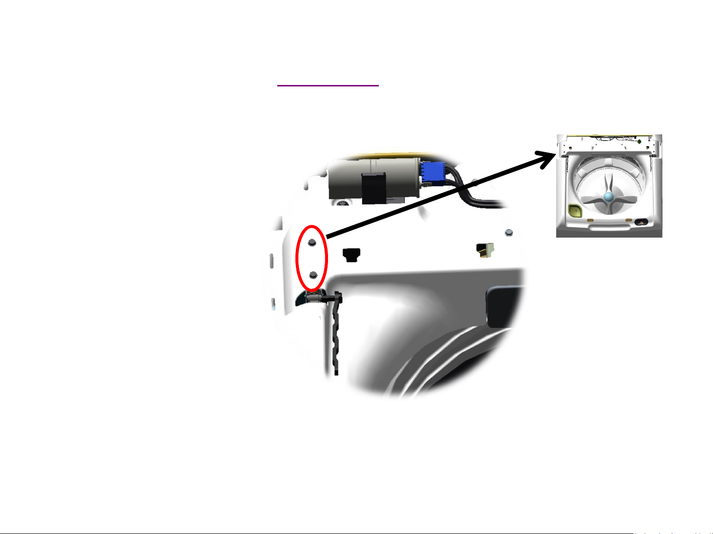
Lid Hinge
Hinge removal can be
achieved without
removing the top cover or
disconnecting the control
panel assembly
completely.
Remove the lid assembly.
Disengage the control
panel from the top cover
and slide toward the rear
to expose the hinge
mounting screws.
Video Link
Page 15

Lid Hinge
Remove the hinge arm by
sliding it away from the
hinge assembly.
Slide a hand between the
tub cover and the top
cover and grasp the hinge
assembly.
This type hinge arm is only on the GTW680 model. All the other models will have the wire form hinge.
Page 16
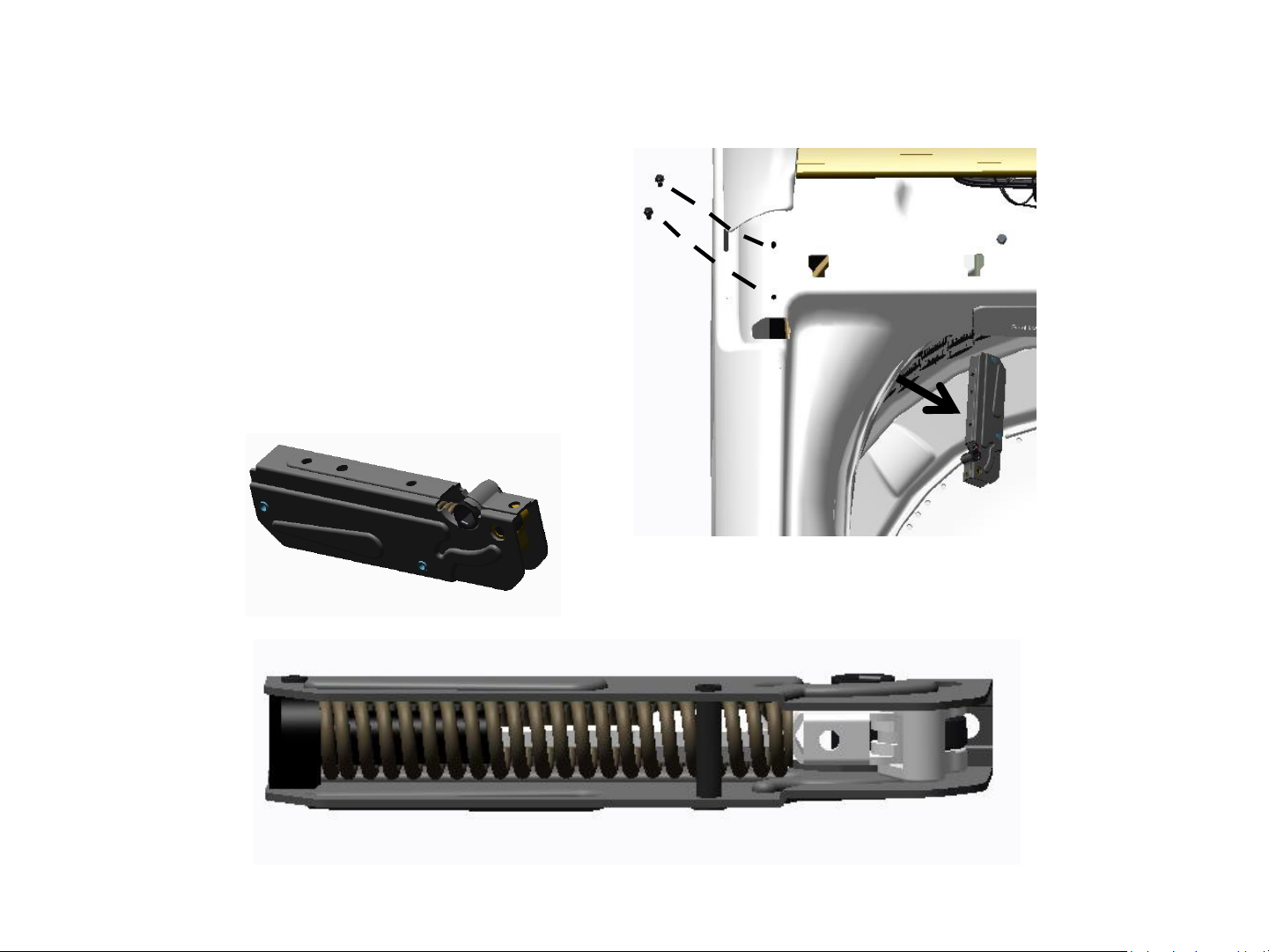
Lid Hinge
Remove the two 1/4 in.
hex head hinge mounting
screws and remove hinge
assembly from under the
top cover.
Page 17
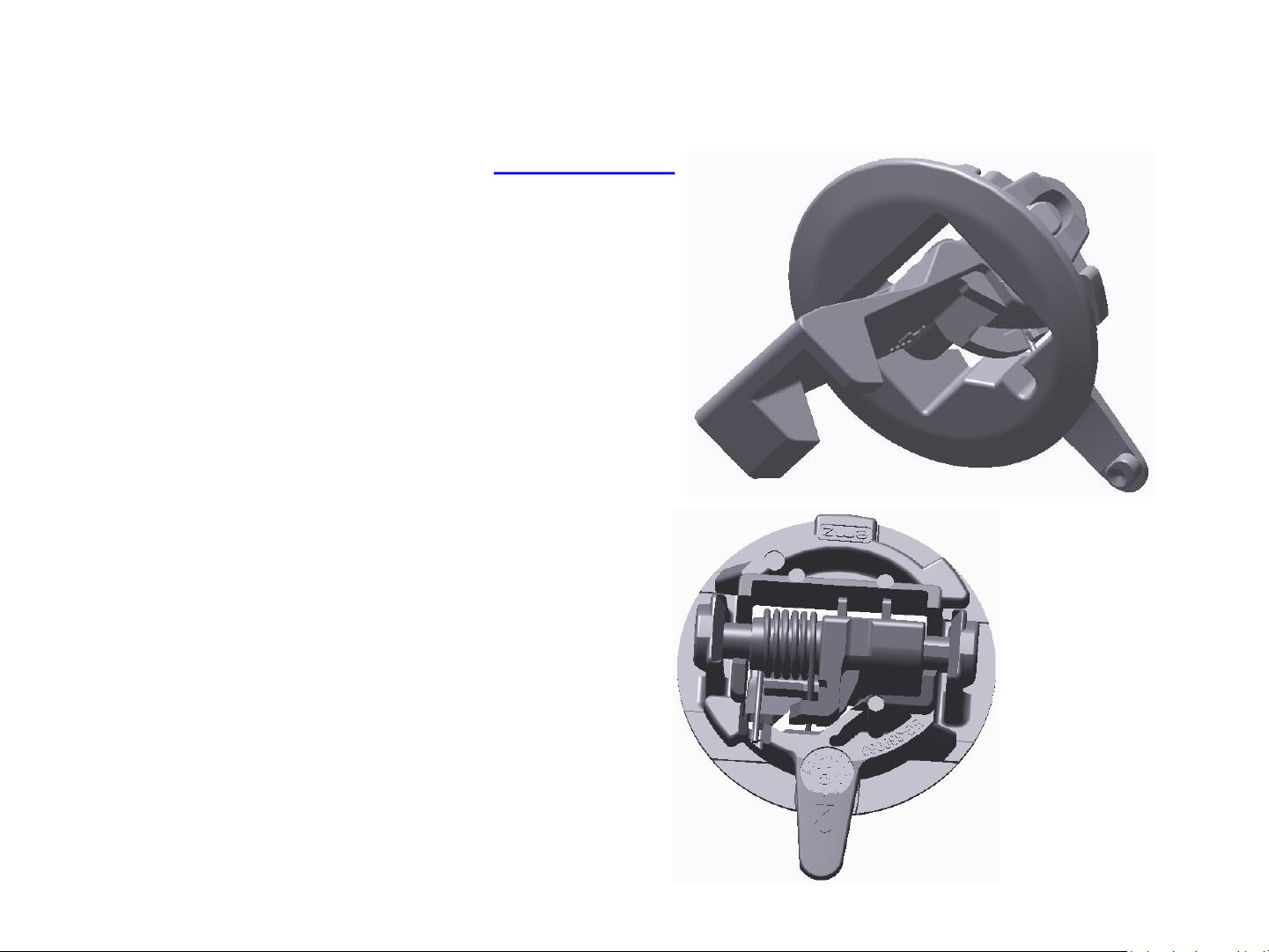
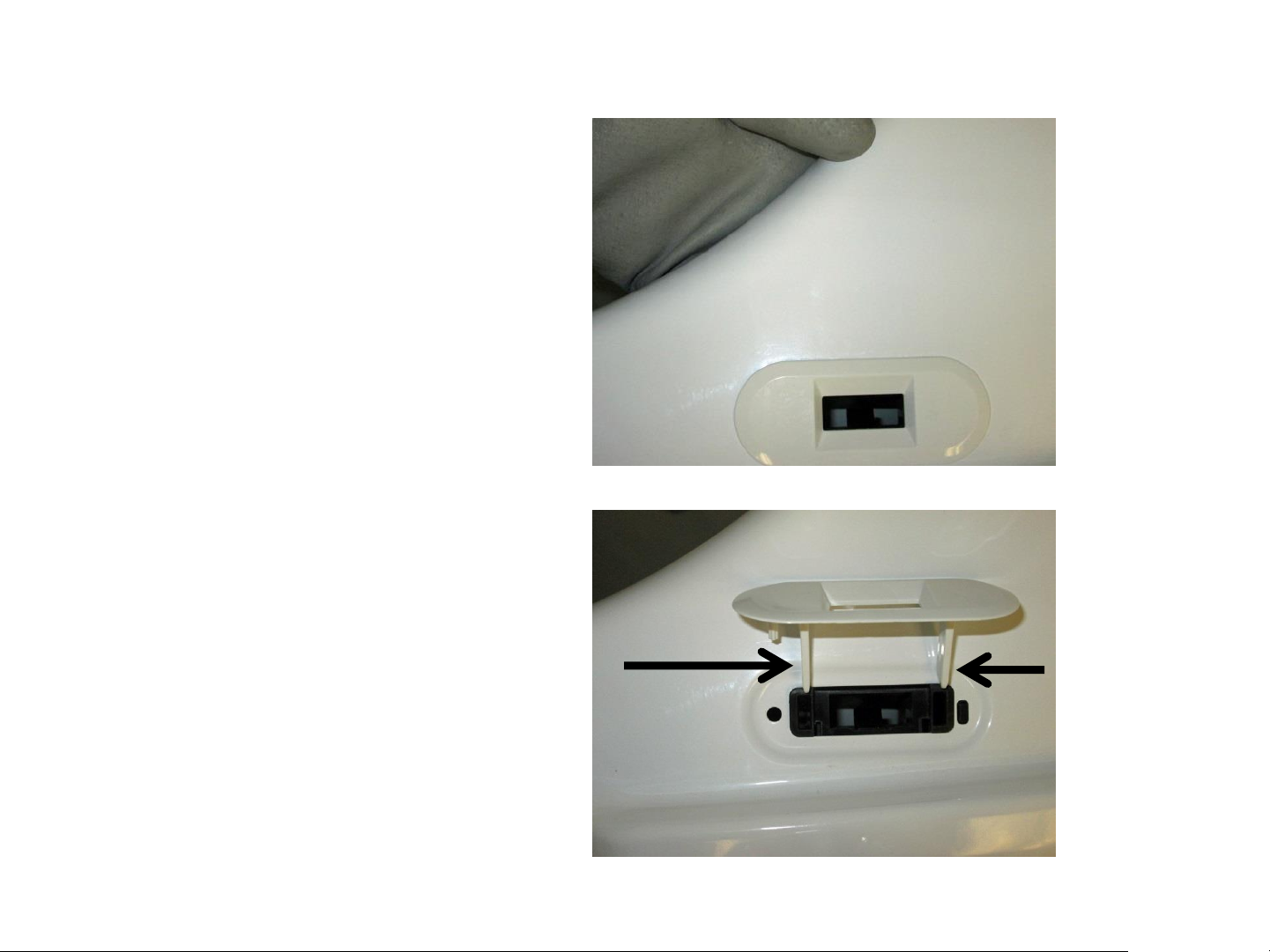
Lid Lock Striker
The lid lock striker slides into
the lid lock/switch assembly.
When a cycle is started the
lock assembly engages with
the striker preventing the lid
from opening during the cycle.
The latch has spring tension on
it to keep it engaged with the
switch/lock assembly.
Video Link
Page 18
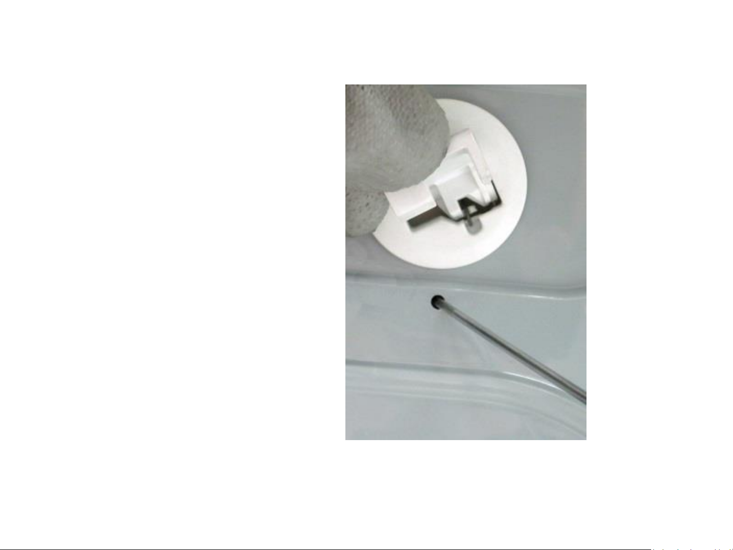
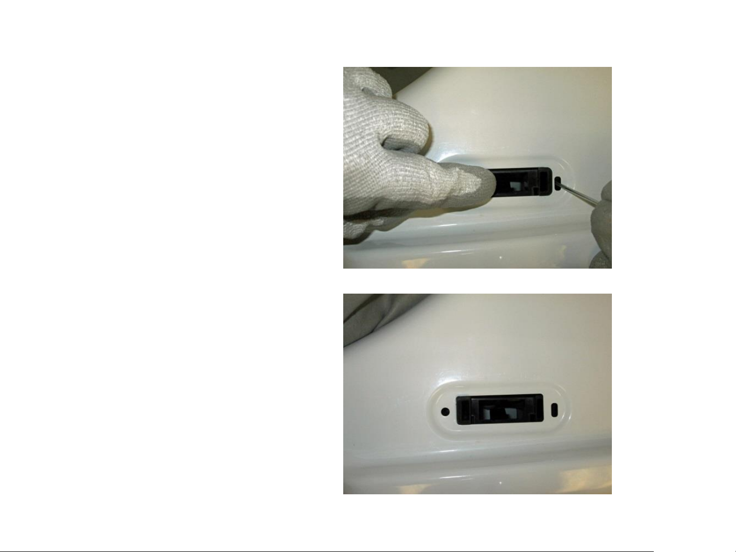
Lid Lock Striker
To remove the striker from
the lid:
Open the lid.
Using a small screwdriver
insert it into the small hole
below the striker.
Push inward gently on the
locking tab and turn the
striker to the left.
Page 19
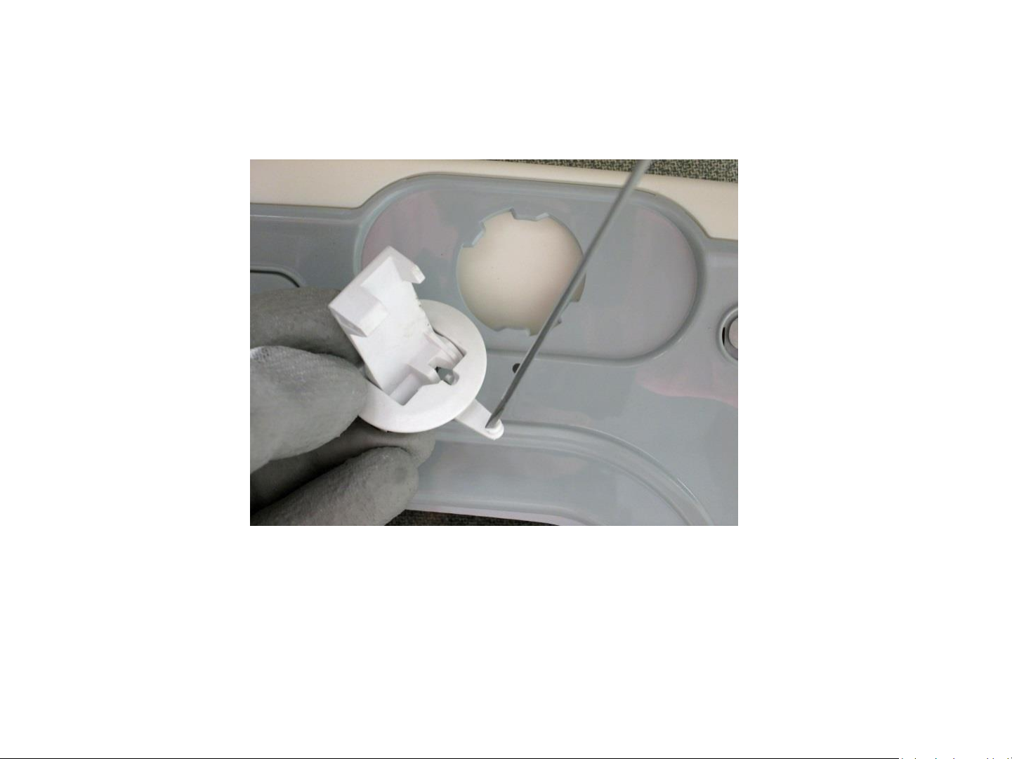
Lid Lock Striker
Pull the striker from the lid.
Page 20
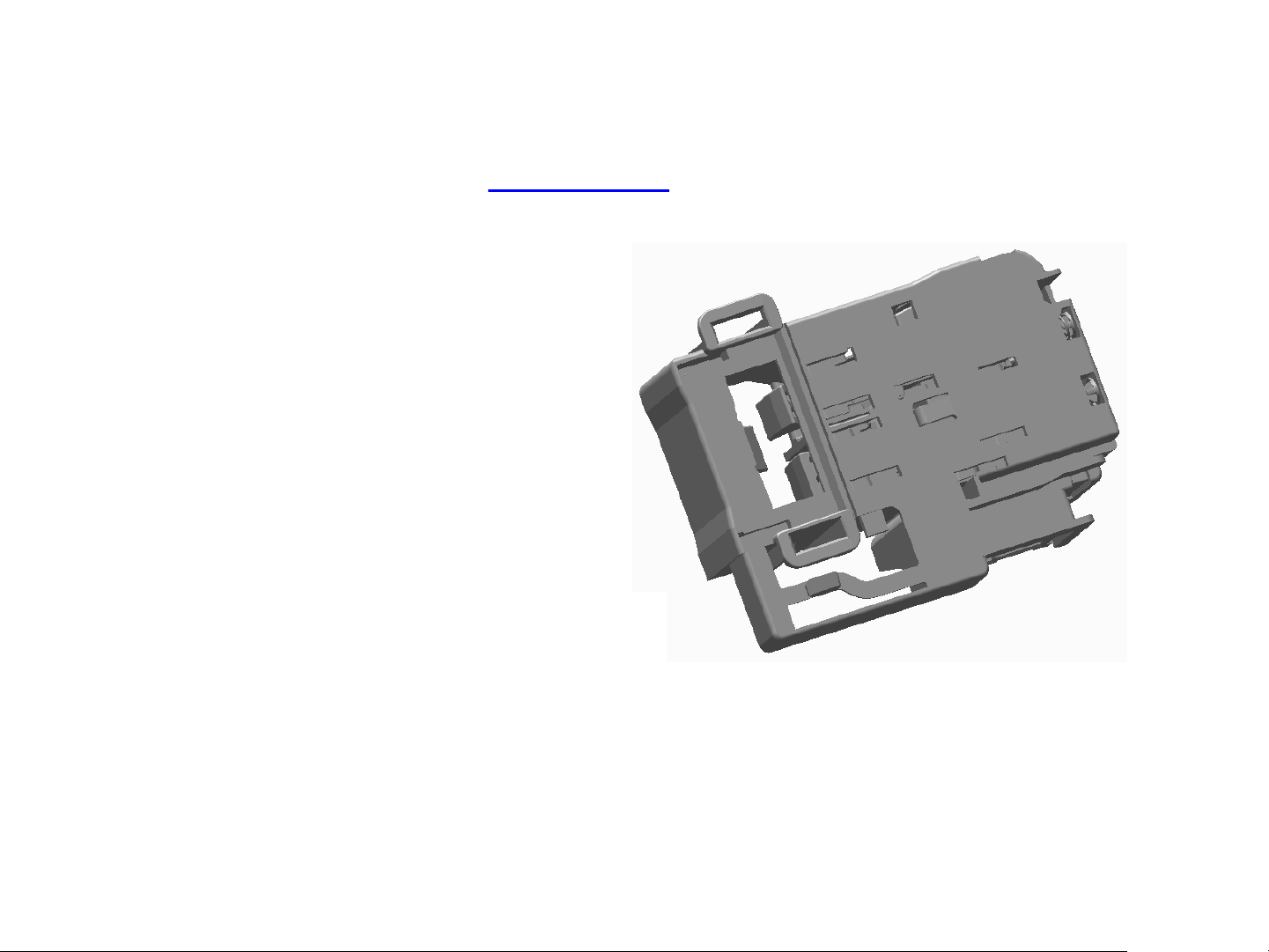
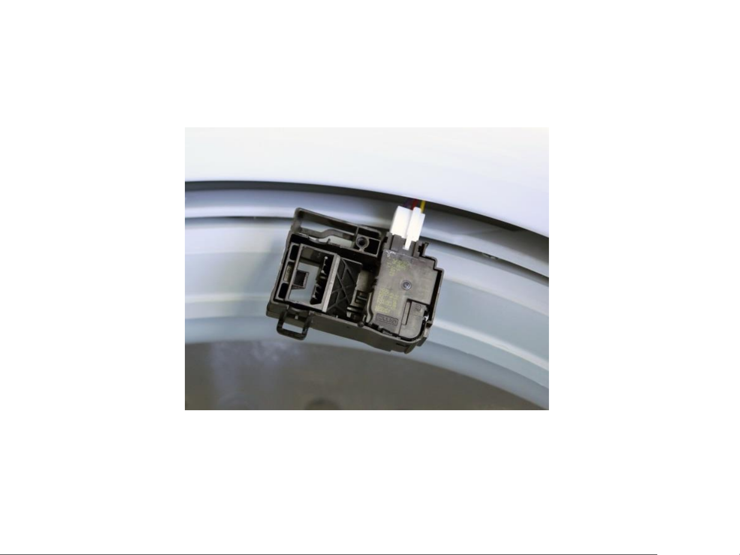
Lid Switch/Lock Assembly
Video Link
The lid lock and switch are together in
one part. It requires 120 VAC to activate
the lock.
The approximate resistance of the lock
coil is 70 ohm from Red – Violet from
J512 board connector.
Checking between Red and Yellow wire at
the same board connector will show the
continuity of the lid switch.
Page 21
Lid Switch/Lock Assembly
To remove the lid switch/lock
assembly:
Remove the bezel from the
top cover by reaching under
the top cover toward the
lock assembly and feel for
the bezel tabs the extend
through the lock body.
Push the tabs out from the
side of the lock body and
then push up to remove the
bezel from the top cover
Tabs
Page 22
Lid Switch/Lock Assembly
Using a small screwdriver,
push down gently on the
tab that prevents the lock
assembly from sliding.
Slide the lock assembly to
the left first to disengage
the right tab, then slide to
the right allowing the lock
assembly disengage
from the top cover.
Page 23
Lid Switch/Lock Assembly
Pull the lock assembly from under the top cover and disconnect the harness connector.
Page 24
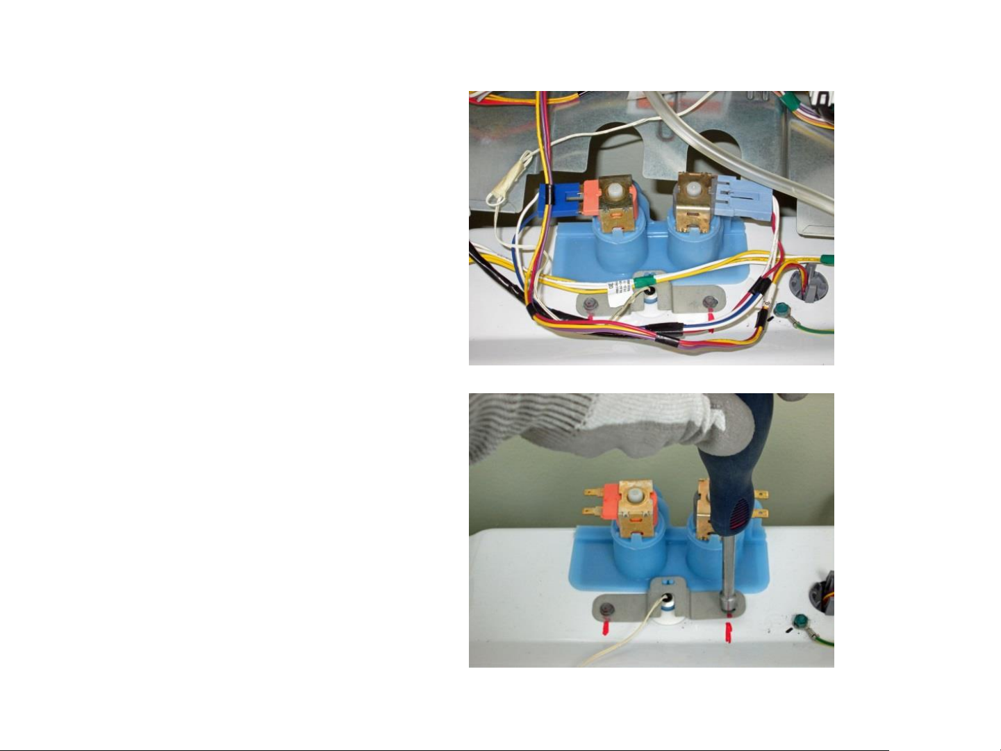
Two Coil Water Valve
Turn water supply off to
valve. Hoses do not need
to be disconnected at
this time.
Remove two 1/4 in. hex
head screws that go
through the thermistor
mounting bracket into
the body of the valve.
24
11/16/2015
Page 25
Two Coil Water Valve
Remove thermistor by pulling up on lip of thermistor. Ensure O-ring is removed with thermistor.
25
11/16/2015
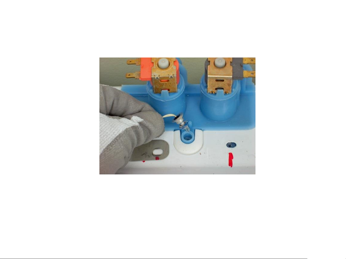
Page 26

Two Coil Water Valve
Tilt back of valve up
and slide out of top
cover. Once valve is
out and held over the
basket, disconnect
hoses.
Valve and funnel are
one part. Gasket can
be ordered separately.
26
11/16/2015
Page 27

Four Coil Water Valve On GTW680 Model
Video Link
27
11/16/2015
Page 28

Four Coil Water Valve Removal
To remove the water valve:
Shut off the water supply
to the washer. Hoses do
not need to be
disconnected at this time.
Lean the control panel
assembly back. It does not
have to be completely
removed.
Disconnect the harness
from the water valve.
28
11/16/2015
Page 29

Four Coil Water Valve Removal
Remove three 1/4 in.
hex head screws
securing the valve to
the top cover and pull
the valve up.
Hold valve over the
basket and disconnect
the supply hoses from
the valve.
There are four
replaceable rubber
seals that seal the
water valve to the
dispenser box.
29
11/16/2015
Page 30

Thermistor Removal
After the water valve is removed the
thermistor can be accessed and remove.
It is pushed into the dispenser box and
held in place by the water valve and is
sealed with an O-ring.
Thermistor
30
11/16/2015
Page 31

Dispenser Removal
The dispenser hold detergent and fabric softener and delivers it at precise times for the
cycle selected. Water is added to the dispenser from the water valve to fill and flush the
cups. After the valve turns off the remaining water in the cup siphons out.
Bleach Funnel
Removal Video
When bleach is added to the bleach cup it is funneled through to the tub cover and into the tub.
Page 32

Dispenser Removal
Remove the backsplash
assembly. water valve
and top cover.
Remove the dispenser
tray from the dispenser
body.
Remove four 1/4 in. hex
head screws from the
top cover securing the
dispenser body to the
top cover.
Page 33

Dispenser Removal
Remove the dispenser body
from the top cover by
pushing back slightly on the
dispenser body and pull
away from top cover.
The dispenser shower insert
can be removed at this time
for cleaning if necessary.
Dispenser shower insert
Page 34

Impeller and Agitators
Impeller
Dual Action
Agitator
Single Action
Agitator
34
11/16/2015
Page 35

Impeller
To remove the impeller, pop the center cap off with a small
screwdriver to access the 7/16th hex bolt. The splined coupler
is part of the impeller and agitators.
Note: Impeller bolt should be replaced any time it is removed
for service and torqued to 100 in-lbs.
35
11/16/2015
Page 36

Dual Stage Agitator
To remove the dual action
agitator, the auger section
needs to be removed to
access the 7/16th hex bolt.
Note: Agitator bolts should
be replaced any time it is
removed for service and
torqued to 100 in-lbs.
36
11/16/2015
Page 37

Dual Stage Agitator Auger Removal
Feel for the small
protrusion near the bottom
of the auger that mounts
to the agitator base.
Turn the top half of the
auger until you feel the
hole located under the
auger fin lines up with the
protrusion.
37
11/16/2015
Page 38

Dual Stage Agitator Auger Removal
Using a thin shanked
screwdriver, tap it
through the hole in the
auger. The inner wall of
the agitator where the
screwdriver pokes
through is thin.
While holding the
basket from spinning
with one hand, use the
screwdriver as a
leverage handle and
twist the auger
assembly clockwise to
remove it from the
agitator base.
Screwdriver
Tap
Through
38
11/16/2015
Page 39

Single Stage Agitator
Remove the single action agitator by taking the agitator cap off to access the 7/16th hex bolt.
The bolt is located inside the agitator at the bottom. A long socket extension (at least 17 in.
long) will be needed to remove it.
Note: Agitator bolts should be replaced any time it is removed for service and torqued to 100
in-lbs.
39
11/16/2015
Page 40

Top Cover Removal
Remove the control panel
assembly.
Slide the harness grommet
out toward the rear of the
washer.
Disengage the power cord
from the top cover by pulling
up on the front of the power
cord grommet.
Pull Up
40
11/16/2015
Page 41

Top Cover Removal
Slide the power cord
grommet forward.
Slide
Forward
41
11/16/2015
Page 42

Top Cover Removal
Pull up off of the top cover.
Pull Up
And Off
42
11/16/2015
Page 43

Top Cover Removal
The harness grommet for
the lid lock does not need to
be removed unless
replacing the top cover.
If replacing the top cover,
squeeze the two clips on
the grommet and push it
through the opening.
Transfer to the new cover.
Remove ground screws.
43
11/16/2015
Page 44

Top Cover Removal
Remove the control panel assembly.
Remove two 1/4 in. hex head screws (one
on each side) at the rear corners of the
top cover.
Slide the harness grommet out toward the
rear of the washer.
Disengage the power cord from the top
cover by lifting up on the front of the cord
grommet, slide forward and up off of the
top cover.
Raise the rear of the top cover up, then
pull forward slightly to disengage from the
front clips that secures the front of the top
cover to the cabinet.
44
11/16/2015
Page 45

Basket Removal
Remove the control panel assembly
and top cover.
Remove the 1-5/16th in. hub nut by
turning the nut clock-wise to loosen
(reverse threads).
A new hub nut should be used
when reinstalling the basket
assembly. Torque to 100 ft. lbs.
45
11/16/2015
Page 46

Basket Removal
Note: A torque limiter (WX05X10028)
should be used when removing or
installing the hub nut with an impact
gun.
Remove the tub cover by unclipping
eight clips around the edge and lift it
off.
Lift the basket out of the tub.
46
11/16/2015
Page 47

Tub And Cabinet Removal/Replacement
Remove the control panel
assembly and top cover.
Disengage the rod and spring
suspension from the tub assembly.
Prop blocks (WX05X10027) x2,
laying on it’s side can be used
under the belt protector.
This will raise the tub assembly up
to disengage the suspension
system.
47
11/16/2015
Page 48

Tub And Cabinet Removal/Replacement
One the suspension is disengaged,
remove the prop blocks letting the
tub assembly rest on the belt
protector.
Raise the cabinet up and over the
tub assembly and set aside.
Note: Be careful of the tub
assembly balance while removing
cabinet.
48
11/16/2015
Page 49

Harness Removal/Replacement
The cabinet needs to be removed to
replace the harness assembly.
Once the cabinet is removed there are
four 1/4 in. hex head screws that
secure the harness to the side of the
tub that need to be removed.
There is one ¼ in. hex head screw on
the bottom and up to six wire ties.
49
11/16/2015
Page 50

Bottom Component View
Front
Suspension
Rod and
Spring
Assembly
View shown without belt
protector and pulleys in place.
Recirculation Pump
(On some models)
Motor Pulley
Fan
Belt Protector
Drive
Motor
Transmission
Supports
Assembly
Belt
Mode
Shifter
Assembly
With Clutch
Harness
Connectors
Transmission
Pulley
Drain Pump
and Internal
Outlet Hose
50
11/16/2015
Page 51

Drain And Recirculation Pump
The drain pump is located on the right side
of the bottom of the tub. It is mounted
directly to the tub secured by three (3) 3/8th
hex head bolts.
The GTW680 model has a recirculation
pump located at the front of the bottom of
the tub. It mounts to the tub the same as
the drain pump.
Both pumps are 120 VAC.
The approximate resistances of the pumps
checked from J512 board connector are:
Drain pump – 13.2 ohms
Recirculation pump – 31.7 ohms
Drain Pump
Video Link
Recirculation Pump
Video Link
51
11/16/2015
Page 52

Drain And Recirculation Pump
Before removing the drain or
recirculation pump any water in the
basket must be removed. This is done by
using a transfer pump.
The transfer pump only comes with one
(1) hose. A standard washer hose can be
used for the outlet side of the pump. Part
number WH41X10207.
Pump out as much of the standing
water in the basket as possible.
Lean the washer back and pump out
the water seen in the basket.
When the drain pump is removed
approximately 1–2 cups of water will
drain out of the pump opening in the
tub.
Transfer Pump WX05X23817
52
11/16/2015
Page 53

Drain And Recirculation Pump
Once the bolts are removed the pump can be pulled from the tub.
Have something to catch excess water. The seal is a separate part
that can be replace if leaking.
53
11/16/2015
Page 54

Drive Belt
The drive belt has six ribs
and can be removed
easily turning the pulley
to walk the belt off.
To reinstall the belt, put
it on the motor pulley
first.
Stretch the belt around
the transmission pulley
as far as it can go.
Then rotate the pulley
until the belt is in place.
Be sure all the ribs of the
belt.
Page 55

Drive Motor
Video Link
Push here
Pull out
There are two different horsepower
motors. One third and one half
horsepower motors. The GTW485,
GTW490 and GTW680 models have the
half horsepower motor. They are both
120 VAC reversible motors .
Resistances are 1/2 hp.- Blue - Red
and Blue - Yellow approx. 3.1 ohm.
1/3rd hp. Approx. 3.8 ohm from J511
board connector.
To remove the motor:
Remove the belt and fan pulley. The
pulley is held on by a 9/16 in. lock nut.
Use a new nut when reinstalling the
pulley and torque to 110 in-lbs.
Disconnect the motor harness
connector.
Page 56

Drive Motor
Hall/Speed
Sensor
Unclip the hall/speed sensor
from the motor.
Remove two 1/2 in. bolt
mounting the motor to the tub
letting the motor come loose
from the platform.
When reinstalling the motor
mounting bolts torque to 170
in-lbs.
Note: If the hall/speed sensor is wire tied to the motor when
replacing the motor. Order both the motor and hall/speed sensor.
Page 57

Mode Shifter Assembly
The mode shifter either engages or
disengages the clutch with the
transmission pulley depending on
whether the cycle is in spin or
agitate.
The clutch home position is engaged
with the pulley or ready for spin.
It has a 120 VAC motor.
Resistance of the mode shift motor
from Brown – Blue is 5700 ohm
from J512 board connector.
To remove the Mode shifter:
Remove the transmission pulley and
nut. The pulley is held on by a 9/16
in. lock nut. Use a new nut when
reinstalling the pulley and torque
to 110 in-lbs.
Guide Pins
Page 58

Mode Shifter Assembly
Disconnect the mode shifter motor
harness connector.
Remove two 3/8th hex head mounting
bolts. This will allow the complete mode
shifter assembly to be removed with the
clutch.
The clutch spring and spring washer will
come off as well. When reinstalling be
sure to install the spring washer before
the clutch spring.
Guide Pin
Location Holes
Page 59

Platform Transmission Assembly
The platform transmission assembly is one
complete part with the exception of two
harness connector brackets and one motor
splash guard. These will need to be
transferred to the new platform assembly
when replacing the platform transmission
assembly.
The platform assembly is secured to the tub
by eight 3/8th hex head bolts circled . One of
these bolts also holds one of the harness
brackets to the platform.
Harness
Connector
Bracket
Motor Shield
Harness
Connector
Bracket
Page 60

Platform Transmission Assembly
To remove the platform assembly after all
other components have been removed
remove the eight 3/8th hex head bolts and
pull the platform away from the tub.
Note: The bottom of the tub can be used to
pry the platform transmission assembly off of
the tub.
The tub seal is pressed on to the platform
transmission assembly. If there is a leak from
the seal, the complete transmission will need
to be replaced.
Triple Lip
Tub Seal
Page 61

Platform Transmission Assembly
To reinstall the platform assembly to
the tub, slide the shaft of the
transmission into the opening of the
tub.
Press the tub seal into the tub
opening.
Note: Line the guide post with the
opening in the platform.
Tighten the eight hex head bolts in a
crisscross pattern so that the seal is
pulled into the tub evenly and
securely.
This is done by tightening each bolt
about 1/4 of the way in at a time.
Torque to 65 in-lbs.
2
3
8
6
5
7
4
1
Guide
Post
Page 62

Schematic
62
11/16/2015
Page 63

Control Board User Interface
J401
J615
J513
J514
J511
J101
J701
J602 J512
63
11/16/2015
Page 64

Consumer Error Mode Entry
64
11/16/2015
Page 65

Consumer Help Indicator
65
11/16/2015
Page 66

Service Mode Entry
66
11/16/2015
Page 67

Binary Display Test and Fault Chart
67
11/16/2015
Page 68

Service Mode Tests
68
11/16/2015
Page 69

Service Mode Tests
69
11/16/2015
Page 70

Service Mode Tests
70
11/16/2015
Page 71

Service Mode Tests
71
11/16/2015
Page 72

Service Mode Tests
72
11/16/2015
Page 73

Service Mode Tests
73
11/16/2015
Page 74

Service Mode Tests
74
11/16/2015
Page 75

Service Mode Tests
75
11/16/2015
Page 76

Service Mode Tests
76
11/16/2015
Page 77

Fault Codes
77
11/16/2015
Page 78

Fault Codes
78
11/16/2015
Page 79

Fault Codes
79
11/16/2015
Page 80

Fault Codes
80
11/16/2015
Page 81

Warranty
81
11/16/2015
 Loading...