

Page 1

g
GE Consumer Home Services Training
TECHNICAL SERVICE GUIDE
Louisville Built
Top Mount No Frost
18-19 Cu. Ft. Energy Refrigerators
MODEL SERIES:
ETS
GTH
GTS
HTS
STS
PUB # 31-9078 12/01
Page 2

!
IMPORTANT SAFETY NOTICE
The information in this service guide is intended for use by
individuals possessing adequate backgrounds of electrical,
electronic, and mechanical experience. Any attempt to repair a
major appliance may result in personal injury and property
damage. The manufacturer or seller cannot be responsible for the
interpretation of this information, nor can it assume any liability in
connection with its use.
WARNING
To avoid personal injury, disconnect power before servicing this
product. If electrical power is required for diagnosis or test
purposes, disconnect the power immediately after performing the
necessary checks.
RECONNECT ALL GROUNDING DEVICES
If grounding wires, screws, straps, clips, nuts, or washers used
to complete a path to ground are removed for service, they must
be returned to their original position and properly fastened.
GE Consumer Home Services Training
Technical Service Guide
Copyright © 2001
All rights reserved. This service guide may not be reproduced in whole or in
part in any form without written permission from the General Electric Company.
Page 3

Table of Contents
Specifications ................................................................................................................. 2
Nomenclature ................................................................................................................. 3
Warranty Information ...................................................................................................... 4
Operating Characteristics............................................................................................. 5
Mechanical Disassembly ............................................................................................... 8
Troubleshooting........................................................................................................... 18
Component Locator Views .......................................................................................... 22
Schematics ................................................................................................................... 24
– 1 –
Page 4
Specifications
DISCONNECT POWER CORD BEFORE SERVICING
IMPORTANT - RECONNECT ALL GROUNDING DEVICES
All parts of this appliance capable of conducting
electrical current are grounded. If grounding wires,
screws, straps, clips, nuts or washers used to
complete a path to ground are removed for service,
they must be returned to their original position and
properly fastened.
ELECTRICAL SPECIFICATIONS
Temperature Control (Position 5) .............................. 24.5-12.5°F
Defrost Control ..................................................... 8 hrs. @ 30 min.
Defrost Thermostat ............................................................ 58-28°F
Electrical Rating: 115V AC 60Hz.
100V AC 50 Hz. .............................................................. 6.5 Amp.
Maximum Current Leakage ............................................. 0.75 mA.
Maximum Ground Path Resistance ........................... 0.14 Ohms
Energy Consumption
18' .............................................................................. 40 KWH/mo
19' .............................................................................. 41 KWH/mo
NO LOAD PERFORMANCE
Control Position, Fresh Food 5, Freezer 5
and Ambient Temperature of: .............................
70°F 90°F
Fresh Food, °F ....................................................... 34-40 35-39
Frozen Food, °F ..................................................... (-3) -4 (-3) -3
Run Time, % .......................................................... 20-30 41-53
IMPORTANT SAFETY NOTICE
This information is intended for use by individuals
possessing adequate backgrounds of electrical,
electronic and mechanical experience. Any attempt
to repair a major appliance may result in personal
injury and property damage. The manufacturer or
seller cannot be responsible for the interpretation
of this information, nor can it assume any liability
in connection with its use.
INSTALLATION
Clearance must be provided for air circulation
AT TOP .....................................................................................1-inch
AT SIDES ............................................................................. 1/8-inch
AT REAR .................................................................................. 1-inch
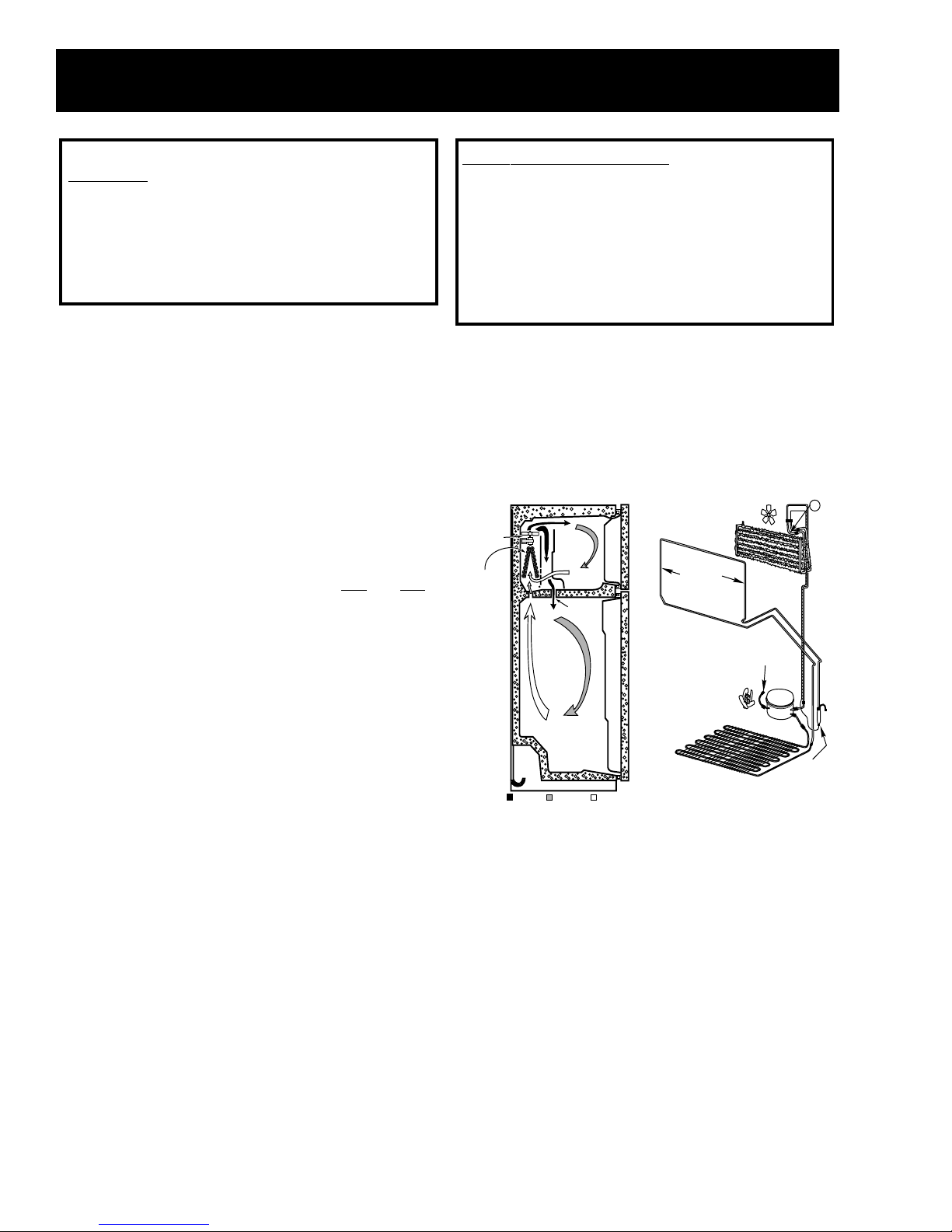
AIR FLOW SEALED SYSTEM
T
FAN
EVAPORATOR
DAMPER
CONDENSER
LOOP
PROCESS
TUBE
REFRIGERATION SYSTEM
Refrigerant Charge (R134a) ........................................ 4.0 ounces
Compressor ................................................................... 679 BTU/hr
Minimum Compressor Capacity ................................... 19 inches
Minimum Equalized Pressure
@70°F ............................................................................... 52 PSIG
@90°F ............................................................................... 66 PSIG
REPLACEMENT PARTS
Condenser Fan Motor ............................................... WR60X10044
Evaporator Fan Motor .............................................. WR60X10057
Defrost Heater ........................................................... WR51X10031
Relay ............................................................................WR07X10031
Overload ........................................................................ WR08X0167
Temperature Control .................................................WR09X10044
Defrost Control ................................................................ WR9X503
Defrost Thermostat ...................................................WR50X10025
Capacitor .................................................................... WR062X0087
COLD AIR
WARMER AIRMIXED AIR
ND103-02B
103-02A
DRYER
– 2 –
Page 5
Nomenclature
CONFIGURATION
T = TOP FREEZER
VOLUME
18 / 19
MODEL YEAR
M = 2001
ENGINEERING
NOMENCLATURE
A = INITIAL DESIGN
B = 1ST REVISION
ETC.
R = RIGHT DOOR SWING -TF
L = LEFT DOOR SWING - TF
G T S 1 8 E B M B R W W
BRAND/PRODUCT
G = GE
S = SELECT
DEPTH/POWER
S = STANDARD
T = TROPICAL
R = RECESSED
HANDLE
Rating Plate
INTERIOR/SHELVES
A = LEADER WIRE
B = STANDARD WIRE
E = PREMIUM WIRE
F = SUPERIOR WIRE
H = UPGRADE GLASS
K = SPILL-PROOF GLASS
X = REGIONAL
ICEMAKER
B = ICEMAKER READY
C = FACTORY ICEMAKER
EXTERIOR COLOR
WW = WHITE/WHITE
AA = ALMOND/ALMOND
CC = BISQUE/BISQUE
T
DOOR TYPE
RATING PLATE
The rating plate, located inside the refrigerator on
the upper left-hand side, contains the model and
serial numbers. Additionally, the rating plate
specifies the minimum installation clearances,
electrical voltage, frequency, maximum
amperage rating, and refrigerant charge and
type.
GEA01027
Mini Manual Location
– 3 –
Page 6

Warranty Information
Refrigerator Warranty.
(For customers in the United States)
For The Period Of: GE Will Replace:
One Year Any part
of the refrigerator which fails due to a defect in materials or workmanship.
From the date of the
During this
full one-year warranty,
GE will also provide,
free of charge,
all labor
original purchase
and in-home service to replace the defective part.
Five Years Any part of the sealed refrigerating system
(the compressor, condenser, evaporator
From the date of the
and all connecting tubing) which fails due to a defect in materials or workmanship.
original purchase
During this
additional four-year limited warranty,
GE will also provide,
free of charge,
all
labor and in-home service to replace the defective part.
■Service trips to your home to teach you how to use the
product.
■Improper installation.
■Failure of the product if it is abused, misused, or used for
other than the intended purpose or used commercially.
■Loss of food due to spoilage.
■Replacement of house fuses or resetting of circuit
breakers.
■Damage to the product caused by accident, fire, floods or
acts of God.
■Incidental or consequential damage caused by possible
defects with this appliance.
What GE Will Not Cover:
This warranty is extended to the original purchaser and any succeeding owner for products purchased for home
use within the USA. In Alaska, the warranty excludes the cost of shipping or service calls to your home.
Some states do not allow the exclusion or limitation of incidental or consequential damages. This warranty gives
you specific legal rights, and you may also have other rights which vary from state to state. To know what your
legal rights are, consult your local or state consumer affairs office or your state’s Attorney General.
Warrantor: General Electric Company. Louisville, KY 40225
All warranty service provided by our Factory Service Centers,
or an authorized Customer Care
®
technician. To schedule service,
on-line, 24 hours a day, contact us at www.GEAppliances.com, or
call 800-GE-CARES.
Staple your receipt here.
Proof of the original purchase
date is needed to obtain service
under the warranty.
– 4 –
Page 7
Operating Characteristics
Note:
Refer to Component Locator Views.
Refer to Schematics.
Component Description
The compressor and dryer are located in the
machine compartment at the bottom, rear of the
unit. The condenser is located under the unit. The
evaporator is located in the freezer compartment
on the back wall.
The capillary is soldered to the compressor
suction line. The capillary is also taped to the
suction line near the dryer. This arrangement
serves as a heat exchanger.
The temperature control and defrost control are
located in the control console. The control
console is located in the top of the fresh food
compartment. The evaporator fan is located in the
freezer compartment behind the air tower.
operates only when the temperature control
(switch) is closed. After 8 hours of motor/cam
mechanism runtime in cooling mode, the defrost
control switches to defrost mode. The defrost
control will stay in defrost mode, providing 115 VAC
to the heater for 30 minutes of motor/cam
mechanism runtime. The defrost thermostat
switch is mounted on the evaporator and, when
closed, completes the neutral side of the defrost
heater circuit. The defrost thermostat switch
opens when the evaporator temperature raises to
58 °F and closes when the evaporator temperature
lowers to 28 °F. The defrost thermostat switch
typically opens during the defrost cycle, preventing
the heater from defrosting for the full 30 minutes.
The purpose for the 30-minute defrost mode at the
defrost control is to prevent the compressor from
operating and refreezing any water that may be
dripping from the evaporator.
Electrical Operation
The power source provides 115 VAC to the
temperature control. The temperature control is a
thermostatic switch that closes when the fresh
food compartment temperature is higher than the
control setting. When closed, the temperature
control provides 115 VAC to the defrost control.
The defrost control contains a motor/cam
mechanism that switches the defrost control
between defrost mode and cooling mode. When
in cooling mode, the defrost control provides
115 VAC to the compressor, condenser fan, and
evaporator fan. The compressor, condenser fan,
and evaporator fan should always operate at the
same time.
Defrost Operation
The automatic defrost function is controlled by the
defrost control. The defrost control contains a
motor/cam mechanism that switches the defrost
control between defrost mode and cooling mode.
The defrost control motor/cam mechanism
FAN
EVAPORATOR
DAMPER
COLD AIR
WARMER AIRMIXED AIR
ND103-02B
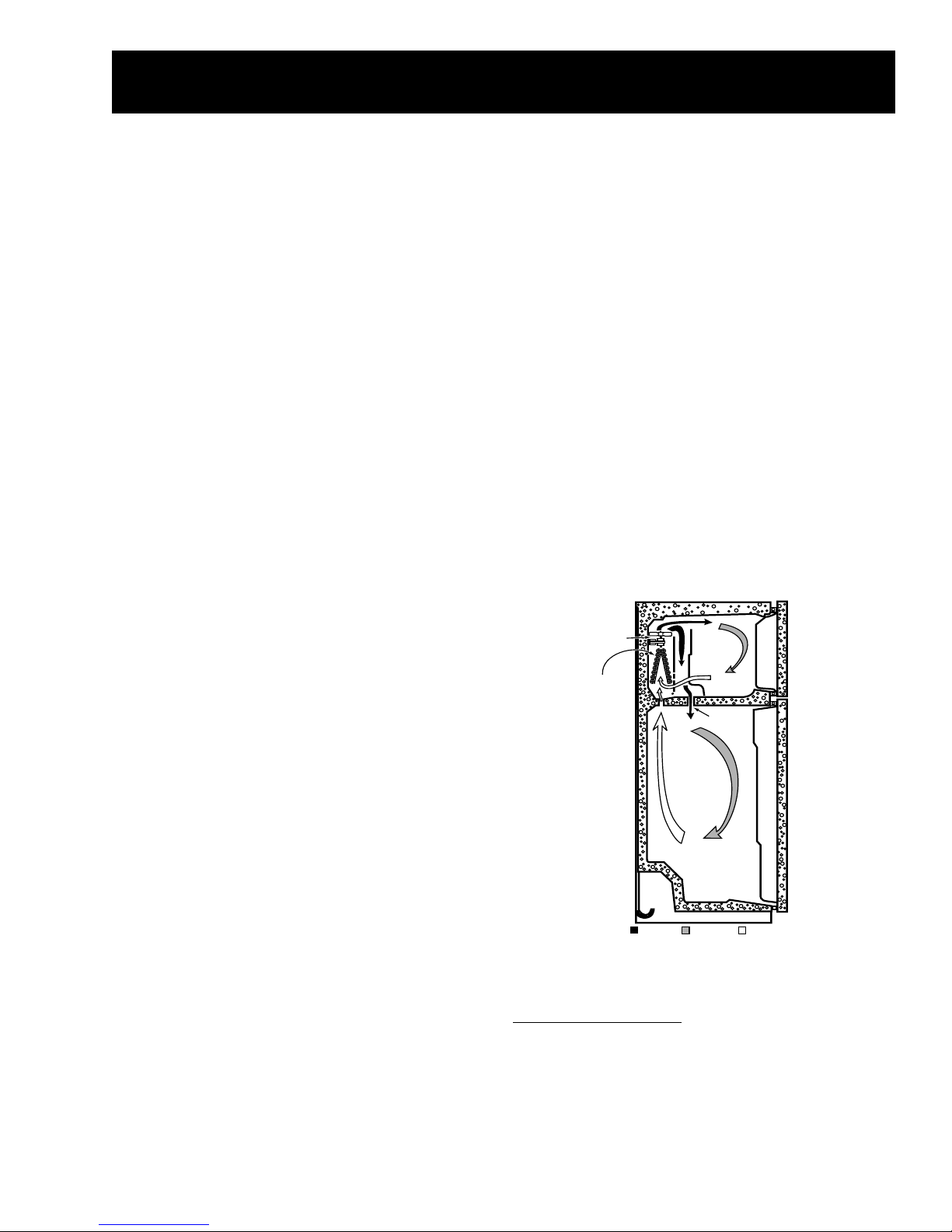
Airflow
Freezer Compartment
Cold air from the evaporator is forced up against
the top of the freezer and the back of the
evaporator cover. It is then discharged through
– 5 –
Page 8
slots along the air tower at the rear of the freezer
compartment.
Air is circulated by the evaporator fan throughout
the freezer compartment, where it picks up heat
and moisture. The evaporator fan then draws the
warmer, moisture-laden air through return louvers
in the bottom of the evaporator cover. The air is
then drawn through the evaporator where heat is
removed and moisture is deposited as frost.
GEA01143
Fresh Food Compartment
Some of the cold air that is being forced against
the top of the freezer and back of the evaporator
cover is diverted through the lower portion of the
freezer air tower and is pushed through the mullion
hole into the damper (in control console).
Air circulates throughout the fresh food
compartment, picking up heat and moisture. The
air is then returned to the evaporator through the
return air ducts located at the top right and left of
the fresh food compartment.
– 6 –
Page 9
Notes
– 7 –
Page 10

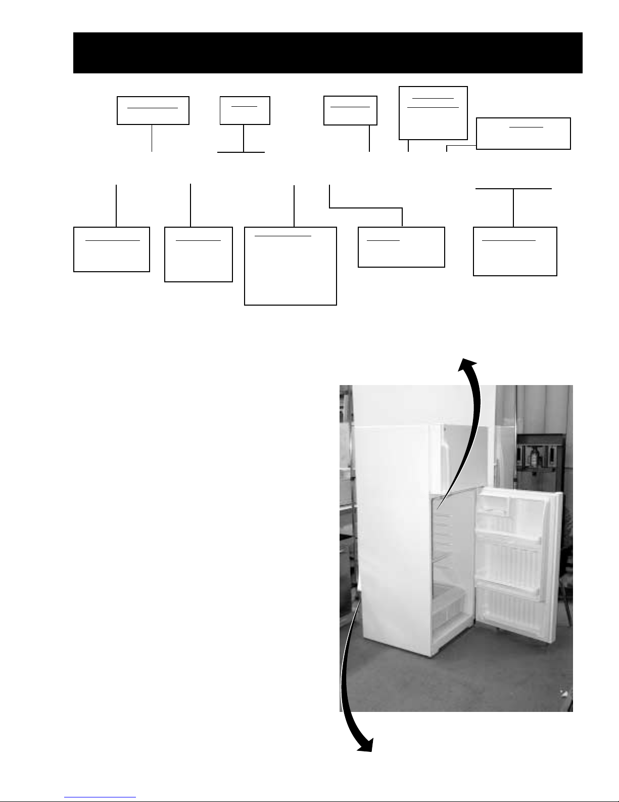
Mechanical Disassembly
Table of Contents
Door Gasket ............................................................................................................. 9
Doors ......................................................................................................................... 9
Roller ........................................................................................................................ 10
Crisper Drawers ...................................................................................................... 10
Temperature Control .............................................................................................. 10
Defrost Control ....................................................................................................... 11
Light Switches ......................................................................................................... 11
Air Tower and Evaporator Cover .......................................................................... 11
Defrost Thermostat ................................................................................................ 12
Defrost Heater ........................................................................................................ 12
Evaporator (Soldering Method) ............................................................................ 12
Evaporator (LOKRING Method) ............................................................................ 13
Evaporator Fan ....................................................................................................... 14
Condenser Fan ....................................................................................................... 14
PTCR Relay/Overload Cover (Compressor) ........................................................ 15
PTCR Relay (Compressor) ..................................................................................... 15
Overload (Compressor) ......................................................................................... 16
Capacitor (Compressor) ......................................................................................... 16
Compressor ............................................................................................................. 16
– 8 –
Page 11
Door Gasket
Top Hinge
The fresh food and freezer doors have magnetic
gaskets that create a positive seal to the front of
the steel cabinet. The magnetic door gaskets are
secured to the fresh food and freezer doors by a
barbed edge that locks into a retainer channel.
GEA01150
1. Starting at any corner, pull the old gasket out of
the retainer channel.
2. Soak the new gasket in warm water to make it
pliable.
3. Push the barbed edge of the gasket into the
retainer channel.
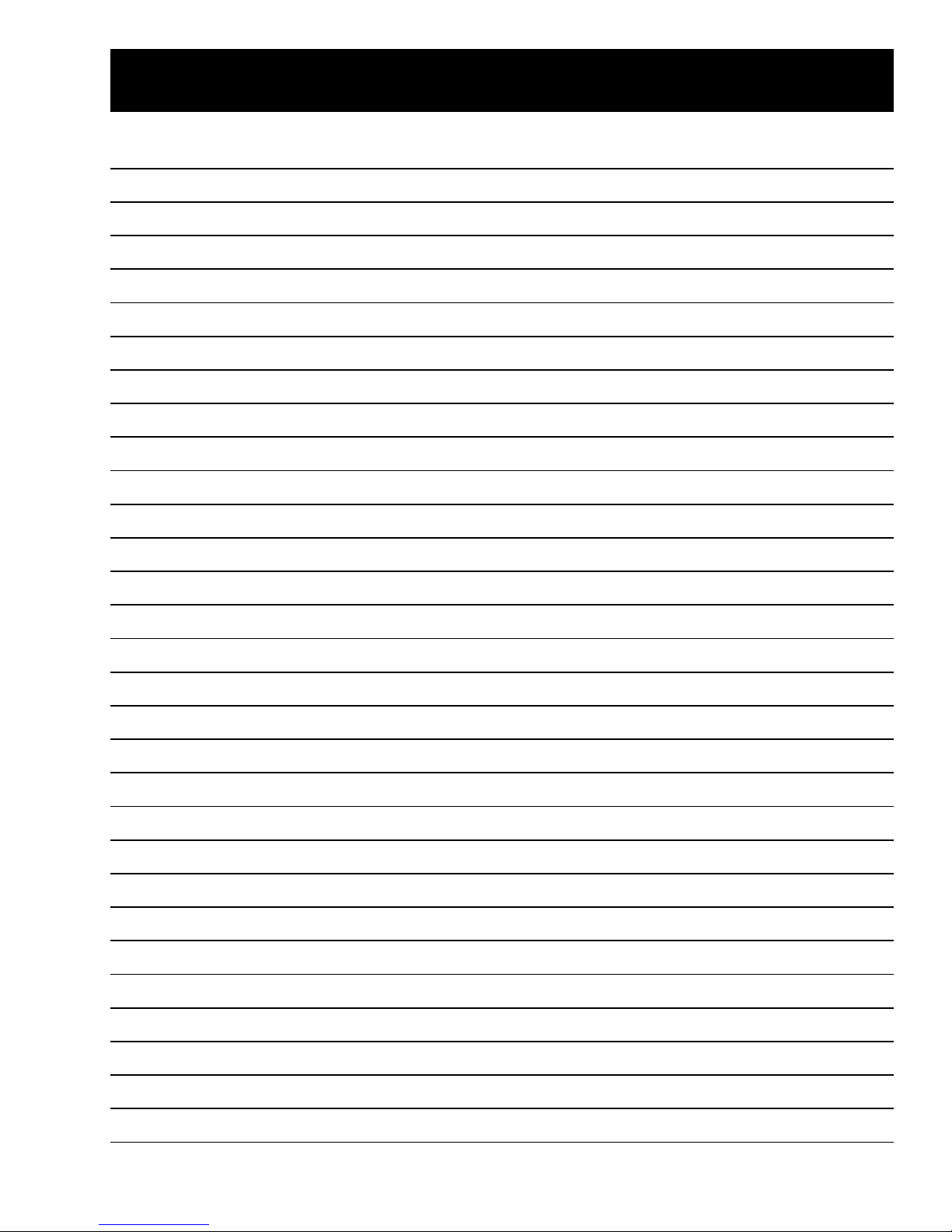
Doors
Vent Holes
GEA01138
The doors are of one-piece construction with foam
insulation. One-piece construction provides
superior thermal performance and reduces air
infiltration. During manufacturing, the doors are
filled with hot foam insulation. This may cause
slight distortion or ripples in the inner door liner.
This is a normal condition and is the result of the
insulating process. This process requires doors
to be equipped with vent holes that allow air to
escape when the door is filled with foam. A small
amount of foam may be visible around the vent
holes.
The inner door panels and outer door panels
cannot be separated and must be replaced as an
assembly.
Freezer Door
1. Remove all food from the inner door liner.
2. Remove 2 screws and the top hinge from the
cabinet.
Note: Do not lose plastic washers on center
hinge pin. Plastic washers are needed for proper
door adjustment.
3. Open the door and lift it off the center hinge pin
to remove.
– 9 –
Page 12

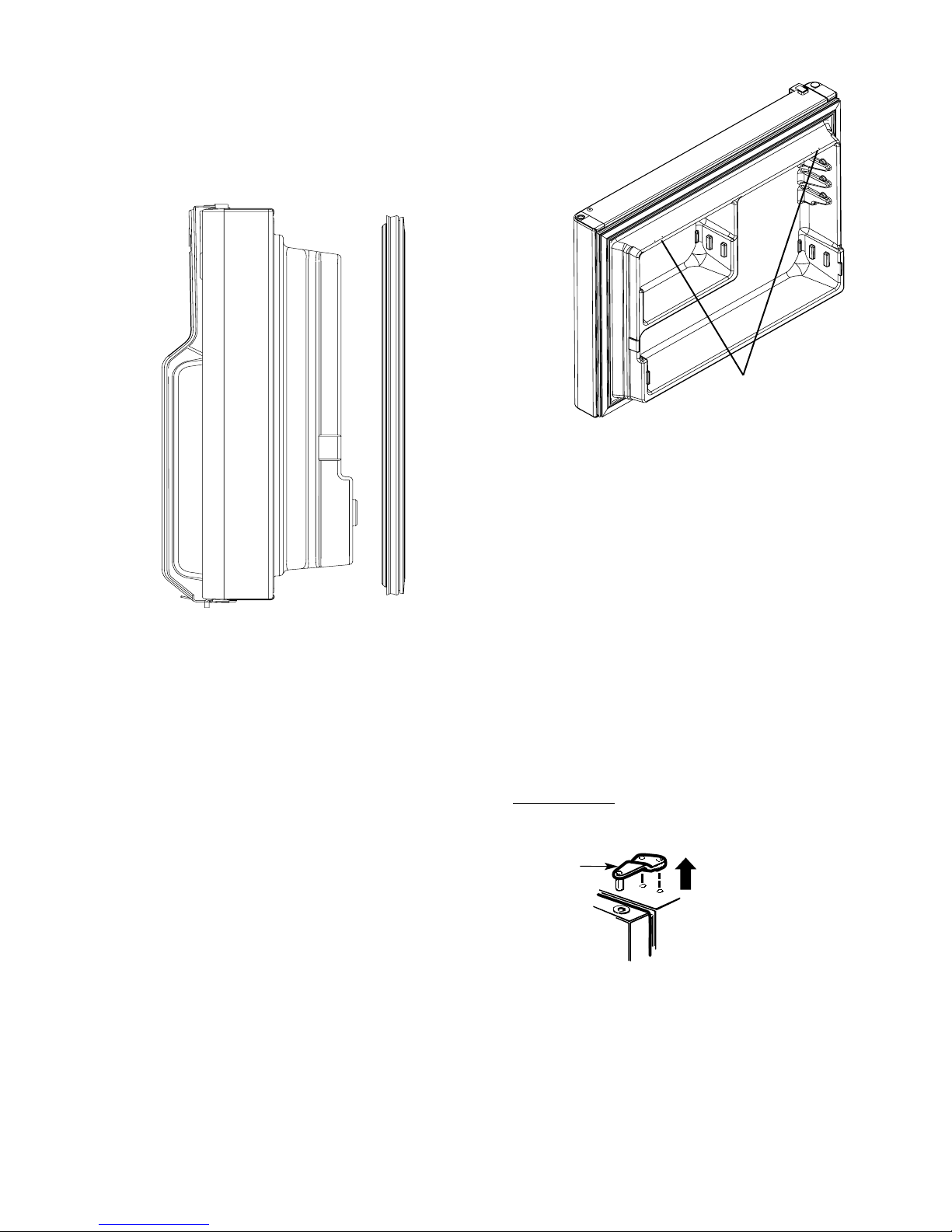
Fresh Food Door
Plastic Washer
Fresh Food Door
Hinge Pin
Center Hinge
Bracket
1. Remove all food from the inner door liner.
Note: Do not lose plastic washers on center
hinge pin and lower hinge pin. Plastic washers
are needed for proper door adjustment.
2. Remove pin and washer from center hinge.
To remove a front roller assembly from the base of
the cabinet:
1. Tilt the cabinet back and place a
3-in. block under the side of the unit.
2. Remove 3 hex head (1/4-in.) screws from the
roller assembly.
3. Loosen the adjustment screw until it
disengages from the assembly and remove
the assembly from the cabinet.
4. Remove the E-ring to remove the adjustment
screw from the base channel.
Note: When reinstalling the roller assembly,
position the nut with the flared thread toward the
rear of the unit.
3. Open the door and lift it off the bottom hinge to
remove.
Rollers
Rollers at the base of the cabinet enable the
customer to easily move the refrigerator. Cabinet
leveling is done by adjusting the front rollers. To
adjust the front rollers, use a 3/8-in. socket or a
large flat head screwdriver to turn the roller
adjustment screws located behind the base grille.
The rear rollers are not adjustable.
Crisper Drawers
Unload the bottom shelf before attempting to
remove the storage drawers.
To Remove:
Lift the drawers up slightly while pulling
them past the stop location.
When the door cannot be fully opened:
Remove the drawer that is farthest from the door.
Slide the other drawer toward the middle and
remove it.
GEA01147
– 10 –
Page 13

Temperature Control
GEA01174
Connector
Defrost
Control
Locking Tabs
Connector
Defrost
Control
Locking Tabs
Release Tab
Light Switch
Defrost Control
1. Remove 3 screws and lower the control
console.
2. Disconnect the harness connector and
remove the control console.
Ground
Ground
Wire
Wire
Temperature
Temperature
Control
Control
Locking
Locking
Tabs
Tabs
Temperature
Temperature
Adjustment
Adjustment
Knob
Knob
Wire
Wire
Leads
Leads
3. Remove knob and clip from temperature
control.
1. Remove the control console (see Temperature
Control procedure).
2. Disconnect the wiring harness connector from
the defrost control.
GEA01172
3. Press the locking tabs back and slide the
defrost control out of the control console.
4. Remove styrofoam duct from control console.
5. Remove capillary from plastic sheath.
Note:
To avoid damage to capillary, it may be
necessary to remove wire connectors from defrost
control and from light socket(s).
Temperature control knob clip will be loose when
knob is pulled from temperature control. Use care
to avoid loosing clip. During installation, clip is
installed after knob is pushed on the temperature
control.
6. Press the locking tab back and slide the
temperature control out of the control console.
7. Disconnect 3 wire leads from the temperature
control.
Light Switches
1. Insert a small flat screwdriver under the right
side of the light switch and release the switch
locking tab.
Release Tab
Release Tab
Light Switch
Light Switch
GEA01171
2. Pull the switch out, disconnect the wire leads,
and remove the switch.
– 11 –
Page 14

Air Tower and Evaporator Cover
Defrost Thermostat
1. Remove all shelves.
1. Remove the evaporator cover (see Air Tower
and Evaporator Cover procedure).
Caution: The thermostat has a metal clip that
fastens it to the line. Defrost thermostat can be
damaged if handled improperly. Use clip to
remove and install thermostat.
Defrost
Defrost
Thermostat
Thermostat
GEA01160
Note: Some models are not equipped with a light
and lens in the light housing. Models without a
light have a plastic cover installed over the light
housing.
2. Remove light lens or plastic cover (models
without light).
3. Remove 2 screws from the bottom of the light
housing.
4. Slide light housing out from 2 pegs.
Disconnect light connector.
5. Remove 2 screws from the air tower.
6. Pull up and remove air tower.
7. Remove 2 screws and evaporator cover with
vent cover.
8. Disconnect ground wire from evaporator cover
and remove evaporator cover from freezer
compartment.
Note:
When installing light housing, ensure that back of
housing is installed on the 2 pegs.
When installing vent on left side of evaporator
cover, vents must direct air down.
2. Remove the thermostat from the line.
3. Cut the thermostat lead wires close to the
thermostat to replace.
Defrost Heater
1. Remove the evaporator cover (see Air Tower
and Evaporator Cover procedure).
Defrost
Defrost
Heater Support
Heater Support
Evaporator
Evaporator
Drain Probe
Wire LeadWire Lead
Drain Probe
2. Remove 2 defrost heater supports and the
evaporator drain probe from the evaporator.
Caution: Do not touch defrost heater glass. Oil
and dirt from hands can cause weak spots on the
glass.
3. Bend the aluminum tabs on the evaporator
back (located at each end of the defrost
heater) and lower the heater out of the
evaporator.
Wire LeadWire Lead
GEA01163
– 12 –
Page 15

4. Disconnect 2 wire leads and remove the
Screws
heater.
Note: Evaporator drain probe assists in defrosting
drain. During assembly, probe must be installed
on evaporator and in drain to prevent drain from
freezing closed.
10. Using a file, score the capillary tube just above
the old solder and break the solder-covered
section off. This will help prevent the capillary
tube from becoming plugged when resoldering.
11. Position the new evaporator in the cabinet.
Insert the suction line and capillary tube into
the evaporator.
Evaporator (Soldering Method)
1. Recover the refrigerant.
2. Remove the evaporator cover (see Air tower
and Evaporator Cover procedure).
3. Remove the defrost thermostat (see Defrost
Thermostat procedure).
4. Remove the defrost heater (see Defrost
Heater procedure).
5. Disconnect ground wire from evaporator and
position all wiring to allow for evaporator
removal.
6. Remove 2 screws that hold the evaporator to
the cabinet.
12. Solder the suction line to the evaporator using
silfos.
13. Solder the capillary tube to the evaporator
using silfos.
Note: Evaporator drain probe assists in defrosting
drain. During assembly, probe must be installed on
evaporator and in drain to prevent drain from
freezing closed.
14. Install a replacement dryer.
15. Evacuate and recharge the system using
currently accepted procedures.
Evaporator (LOKRING Method)
1. Recover the refrigerant.
2. Remove the evaporator cover (see Air Tower
and Evaporator Cover procedure).
3. Remove the defrost thermostat (see Defrost
Thermostat procedure).
Screws
Screws
GEA01164
Caution:
If desoldering the evaporator, HEAT SHIELD P/N
WR49X10025 must be used to prevent damage to
freezer liner.
Protect wiring from heat during desoldering and
resoldering.
To prevent damage to the capillary tube, the
capillary tube must be desoldered first.
7. Desolder the capillary tube from the
evaporator.
8. Desolder the suction line. Use a pair of pliers
to hold the evaporator.
9. Remove the evaporator.
4. Remove the defrost heater (see Defrost
Heater procedure).
5. Disconnect ground wire from evaporator and
position all wiring to allow for evaporator
removal.
6. Loosen 2 screws that hold the evaporator to
the cabinet.
Caution: Tubing must be clean and free from
burrs when using LOKRING.
Note: LOKRING connector P/N WR97X10021
must be used. Two LOKRING connectors are
required.
7. Replace the evaporator using the LOKRING
method (see Pub # 31-9067).
Cut the copper lines of the old evaporator as
close as possible to the aluminum evaporator
tubes.
Cut the copper lines of the new evaporator
1-1/8 in. from the edge of the aluminum
evaporator tubes.
– 13 –
Page 16

Cut
Here
Copper
Evaporator
Copper
Cut
Here
Cut
Here
Cut
Here
Aluminum
Evaporator Tubes
Aluminum
Evaporator Tubes
Copper
Evaporator
Defrost
Thermostat
Here
Copper
Evaporator
Evaporator
Lines
Lines
Cut
Cut
Here
Here
Aluminum
Aluminum
Evaporator Tubes
Cut
Cut
Here
Here
Evaporator Tubes
OLD EVAPORATOR
Defrost
Defrost
Thermostat
Thermostat
Here
Here
Evaporator Fan
1. Remove the evaporator cover (see Air tower
and Evaporator Cover procedure).
2. Disconnect the fan motor connector.
3. Carefully pull the fan off the shaft.
Note: Evaporator drain probe assists in defrosting
drain. During assembly, probe must be installed on
evaporator and in drain to prevent drain from
freezing closed.
Copper
Copper
Evaporator
Evaporator
Lines
Lines
Cut
Cut
Here
Here
1-1/8 inch
1-1/8
inch
Aluminum
Aluminum
Evaporator Tubes
Cut
Cut
Here
Here
Evaporator Tubes
NEW EVAPORATOR
GEA01108
4. Remove 2 screws and fan assembly.
5. Remove fan motor.
Note: The position of the fan blade in relation to
the shroud is critical. Refer to figure below for
specifications.
5/16" ± 0.03
1.0" ± 0.05 Target
Blade tip
Motor
Air Flow
Airflow
Orifice
GEA01149
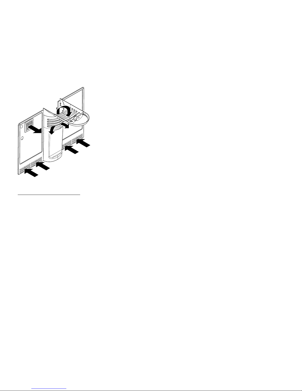
Condenser Fan
1. Remove the machine compartment cover.
2. Disconnect the fan motor connector.
3. Carefully push the fan off the motor shaft.
8. Install a replacement dryer.
9. Evacuate and recharge the system using
currently accepted procedures.
– 14 –
Page 17

Connector
GEA01207
Connector
Screws
Screws
Fan
Fan
Fan MotorFan Motor
GEA01175
4. Remove 2 screws, bracket, and the fan motor.
Caution: During installation, water valve
connector must be tied clear of fan operation.
Note:
PTCR Relay/Overload Cover (Compressor)
1. Remove the machine compartment cover.
Tab
Tab
Cover
Cover
GEA01169
2. Insert a flat screwdriver under the tab on the
covers top surface, pry up, and remove.
The position of the fan blade in relation to the
shroud is critical. Refer to figure below for
specifications.
Ensure that harness connectors are connected
completely and that connector clips are engaged.
If connectors are not connected correctly, they
may vibrate apart.
1/2"
Housing
Fan
0.375"
Motor
3. Remove the cover.
PTCR Relay (Compressor)
1. Remove the PTCR relay/overload cover (see
procedure).
Air Flow
Airflow
0.50" ± 0.05
Bracket
2. Pull the PTCR relay straight out from the
compressor.
3. Disconnect the wire leads from the relay.
GEA01148
– 15 –
Page 18

Overload (Compressor)
Capacitor
Wire Leads
Compressor
1. Remove the PTCR relay/overload cover (see
procedure).
2. Remove the PTCR relay (see procedure).
3. Pull the overload straight out from the
compressor.
4. Disconnect the wire lead from the overload.
Capacitor (Compressor)
1. Remove the machine compartment cover.
Wire Leads
Wire Leads
Capacitor
Capacitor
Note:
Capillary tube must be clipped to compressor
suction line near the dryer. If capillary tube is not
clipped to suction line, a knocking noise may occur
during compressor operation.
The channel in which the compressor is
mounted must be disengaged from the cabinet to
remove the compressor.
Ensure that harness connectors are connected
completely and that connector clips are engaged.
If connectors are not connected correctly, they
may vibrate apart.
Refer to the compressor replacement instructions
included with the replacement compressor.
GEA01168
2. Disconnect the wire leads from the capacitor.
3. Discharge the capacitor with a screwdriver.
4. Remove 1 screw and the capacitor.
– 16 –
Page 19

Notes
– 17 –
Page 20

Troubleshooting
Note:
Refer to Operating Characteristics before
choosing a troubleshooting procedure.
Refer to Schematics.
Refer to Component Locator Views.
Compressor Knock
Capillary tube not taped to suction line. Check
to see that capillary tube is clipped to the suction
line near the dryer.
Low or No Cooling
Check for the following problems:
1. Condenser dirty/clogged. Unplug unit and
clean condenser and underside of refrigerator.
2. Interior lights remain on. Check to see that
interior lights turn off when door switch is
pressed.
3. Door gasket does not seal. Check for
damaged or leaking door gasket.
4. Compressor does not operate. Go to
Compressor Does Not Operate
troubleshooting.
5. Condenser fan does not operate. Go to
Condenser Fan Does Not Operate
troubleshooting.
6. Evaporator fan does not operate. Go to
Evaporator Fan Does Not Operate
troubleshooting.
7. Evaporator is frosted. Go to Defrost System
Check.
Compressor Does Not Operate
Check for the following problems:
Note: The defrost control must be in cooling
mode to operate the compressor (provide
115 VAC to the compressor overload). It may be
necessary to manually rotate the defrost control
to cooling mode before checking for voltage at the
compressor overload.
1. 115 VAC not present at compressor
overload. If 115 VAC is not present at the
compressor overload, check for an open
temperature control or an open defrost control
(cooling mode - terminals 3 and 4 are closed).
Note: The compressor, condenser fan, and
evaporator fan should always operate at the same
time. If the condenser fan is operating, the
temperature control and defrost control
are OK.
2. Overload open. High heat or high current
draw will cause the overload to open. The
overload should close when the temperature
lowers to normal or when normal current draw
is present.
3. PTCR relay open.
4. Run capacitor faulty.
5. Open wire or faulty connector. Refer to
Schematics.
6. Compressor motor faulty. Check resistance
across the compressor motor. Refer to
Schematics for resistance values.
7. Compressor mechanically stalled.
8. Duct is clogged between freezer
compartment and fresh food compartment.
If fresh food compartment is warm and freezer
is normal or too cold, duct (diffuser) may be
clogged. Duct is accessed by removing air
tower.
9. Refrigeration system faulty. Go to
Refrigeration System Check.
Condenser Fan Does Not Operate
Check for the following problems:
1. Condenser fan faulty.
2. 115 VAC not present at condenser fan.
The compressor, condenser fan, and
evaporator fan should always operate at the
same time. If the compressor is operating, the
temperature control and defrost control are
OK.
3. Orange wire open on neutral side of
condenser fan. Refer to Schematics.
– 18 –
Page 21

Evaporator Fan Does Not Operate
Check for the following problems:
Check for the following problems:
1. Evaporator fan faulty.
2. 115 VAC not present at evaporator fan. The
compressor, condenser fan, and evaporator
fan should always operate at the same time. If
the compressor and condenser fan are
operating, the temperature control and defrost
control are OK.
3. Orange wire open on neutral side of
evaporator fan. Refer to Schematics.
Light Does Not Illuminate
Check for the following problems:
1. Lamp faulty.
2. Door switch open. Check continuity across
the door switch with the wires disconnected.
3. Open wire or faulty connector. Refer to
Schematics.
Defrost System Check (Freezer)
1. Defrost heater open. Check resistance
across the defrost heater. Refer to Schematics
for resistance values.
2. Defrost thermostat switch stuck open. The
defrost thermostat switch opens when the
evaporator temperature raises to 58 °F and
closes when the evaporator temperature
lowers to 28 °F.
3. Defrost control open in defrost mode.
Manually rotate the defrost control into defrost
mode. Check for continuity across the defrost
control between terminals 2 and 3. Refer to
Schematics.
4. Open wire or faulty connector. Refer to
Schematics.
5. Clogged or frozen drain. Check for a
clogged or frozen drain. If frozen, see Heat
conducting clip not installed below.
6. Heat conducting clip not installed. If the
heat conducting clip is not installed on the
evaporator and in the drain, the drain may
freeze closed.
The automatic defrost function is controlled by the
defrost control. The defrost control contains a
motor/cam mechanism that switches the defrost
control between defrost mode and cooling mode.
The defrost control motor/cam mechanism
operates only when the temperature control
(switch) is closed. After 8 hours of motor/cam
mechanism runtime in cooling mode, the defrost
control switches to defrost mode. The defrost
control will stay in defrost mode, providing
115 VAC to the heater for 30 minutes of motor/cam
mechanism runtime. The defrost thermostat
switch is mounted on the evaporator and, when
closed, completes the neutral side of the defrost
heater circuit. The defrost thermostat switch
opens when the evaporator temperature raises to
58 °F and closes when the evaporator
temperature lowers to 28 °F. The defrost
thermostat switch typically opens during the
defrost cycle, preventing the heater from
defrosting for the full 30 minutes. The purpose for
the 30-minute defrost mode at the defrost control
is to prevent the compressor from operating and
refreezing any water that may be dripping from the
evaporator.
– 19 –
Page 22

Refrigeration System Check
CHECK SUCTION PRESSURE
SUCTION PRESSURE IN VACUUM
MAKE LEAK-RESTRICTION TEST
CONDENSER TEMPERA TURE
INCREASES THROUGHOUT
SYSTEM HAS LEAK SYSTEM IS RESTRICTED
CHECK FOR LEAKS
AT ALL JOINTS
IN MACHINE COMPARTMENT
FOUND LEAK NO LEAK FOUND
REPAIR LEAK, INSTALL
DRYER AND RECHARGE
CHECK EVAPORATOR
FOR LEAKS
NO CHANGE IN CONDENSER
TEMPERATURE (LOWER 2/3)
INSTALL DRYER
AND RECHARGE
Check high pressure joints with
compressor running and condenser
fan stopped
Add refrigerant
3 oz. - systems <6 oz.
4-1/2 oz. - systems >6 oz.
Wait 4 minutes
REPLACE
COMPRESSOR
Check low pressure joints
with compressor stopped and
defrost heaters energized
SUCTION PRESSURE
ABOVE ZERO
MAKE COMPRESSOR
CAP A CITY TEST
P ASSED TESTFAILED TEST
COMPRESSOR IS OK
LOOK ELSEWHERE
FOUND LEAK
IN EVAPORATOR
REPLACE LO-SIDE
AND INSTALL DRYER
NO LEAK FOUND
IN EVAPORATOR
RECHECK TUBING IN
MACHINE COMPARTMENT
GEA00862
– 20 –
Page 23

Notes
– 21 –
Page 24

Component Locator Views
DryerDryer
Icemaker
Icemaker
Connector
Connector
Compressor
Compressor
Figure 1 - Machine Compartment
Relay and Overload
Relay and Overload
(Under Cover)
(Under Cover)
Condenser
CondenserCondenser
Evaporator FanEvaporator Fan
Condenser
Condenser
Fan
Fan
Evaporator Fan
Evaporator Fan
Connector
Connector
Machine
Machine
Harness Connector
Harness Connector
Water Valve
Water Valve
Connector
Connector
Overtemperature
Overtemperature
Thermostat
Thermostat
GEA01154
Defrost Heater
Defrost Heater
Support
Support
Figure 2 - Evaporator and Associated Parts
– 22 –
EvaporatorEvaporator
Evaporator
Evaporator
Drain Probe
Drain Probe
Defrost HeaterDefrost Heater
GEA01155
Page 25

Defrost
Defrost
Control
Control
Temperature
Temperature
Control
Control
Figure 3 - Control Console
Light
Light
Light
Light
Switch
Switch
Connector
Connector
GEA01166
– 23 –
Page 26

Schematics
FRESH FOOD LIGHT(S)
ORANGE
WHITE
WATER VALVE
(WHEN USED)
1
BROWN
ICEMAKER (WHEN USED)
OVERLOAD
CR
S
COMPRESSOR
7
6
25
T
P.T.C.
RELAY
ORANGE
ORANGE ORANGE
ORANGE
ORANGE
DEFROST
TIMER
1
3
TEMPERATURE
CONTROL
GRAY
BROWN
BROWN
BROWN
ORANGE
ORANGE
ORANGE
RED
FREEZER LIGHT
(WHEN USED)
BROWN
ORANGE
RED
ORANGE
BLACK
BLACK
CONDENSER FAN
BLACK
BLACK
6
EVAPORATOR FAN
ND103-02D
6
ORANGE
4
2
3
7
6
2
BLUE
DEFROST
HEATER
YELLOWPINK
DEFROST
THERMOSTATS
DEFROST
THERMOSTAT
36
(SEE DIAGRA M INSIDE ICEMAKER COVER)
4
8
78
100
190
ORANGE
– 24 –
Page 27

C
R
S
3
2
TO CABINET
WIRING
OVERLOAD
RELAY
RUN CAPACITOR
ORANGE
WHITE
BLACK
GREEN
(GROUND)
KB5006
TEMPERATURE
CONTROL
CONTROLCONTROL
CONNECTORCONNECTOR
CONTROL
CONNECTOR
LIGHT
SWITCH
TO COMPRESSOR
COMPRESSOR
GND
DEFROST
HEATER
FRESH
FOOD
LAMP(S)
DEFROST
TIMER
BROWN
RED
BROWN
GRAY
GRAY(3)
BLUE(2)
BLACK(4)
ORANGE(1)
BLACK
ORANGE
WHITE
3 BROWN
2 BLACK
1 WHITE
6 BLUE
ORANGEORANGE8 ORANGE
HARNESS CONNECTOR
4 PINK
BROWN
ORANGE
BLUE
GREEN
WHITE
WHITE
BLACK
G
Y
BLACK
EVAP
GROUND
EVAPEVAP
COVERCOVER
GROUNDGROUND
EVAP
COVER
GROUND
GREEN
YELLOW
RED
PINK
ORANGE
ORANGE
ORANGE
ORANGE
ORANGE
EVAPORATOR
FAN
CONNECTOR
FREEZER
LIGHT
(WHEN USED)
FREEZER
LIGHT
SWITCH
(WHEN USED)
DEFROST
THERMOSTAT
TO ICEMAKER
(WHEN USED)
POWER
CORD
TO WATER VALVE
(WHEN USED)
MACH
HARNESS
CONNECTOR
TOTO
CONDENSERCONDENSER
FAN MOTORFAN MOTOR
CONNECTORCONNECTOR
TO
CONDENSER
FAN MOTOR
CONNECTOR
ND103-02C
8
7
7
ORANGE
ORANGE
– 25 –
Page 28

Parts List
Note: The components shown in this drawing may
differ from the components in your unit. Refer to the
microfiche or GEA IPC for the component and part
number for your unit.
– 26 –
Page 29

Note: The components shown in this drawing may
differ from the components in your unit. Refer to the
microfiche or GEA IPC for the component and part
number for your unit.
– 27 –
Page 30

Note: The components shown in this drawing may
differ from the components in your unit. Refer to the
microfiche or GEA IPC for the component and part
number for your unit.
– 28 –
Page 31

Note: The components shown in this drawing may
differ from the components in your unit. Refer to the
microfiche or GEA IPC for the component and part
number for your unit.
– 29 –
Page 32

Note: The components shown in this drawing may
differ from the components in your unit. Refer to the
microfiche or GEA IPC for the component and part
number for your unit.
– 30 –
Page 33

– 31 –
Page 34

Note: The components shown in this drawing may differ from the components in your unit. Refer to the
microfiche or GEA IPC for the component and part number for your unit.
GTS18DBMBLAA
VIEW CATALOG NUMBER DESCRIPTION QTY
1 31-51377 PM MINI MANUAL WIRING 1
1 49-60102 USE & CARE MANUAL 1
2 WR12X10426 PK HANDLE SMALL ASM 1
7 WR12X10427 HANDLE ASM FZ AD 1
11 WR12X10428 HANDLE DOOR ASM FF AD 1
18 WR1X1726D SCR 10-16 AB 3/4 SS 7
23 WR24X10095 GASKET DOOR FZ WH 1
24 WR02X10740 STOP DOOR FF 1
26 WR02X10759 STOP DOOR FZ AD 1
29 WR02X8088 PLUG BUTTON INSERT AD 2
35 WR04X10029 LENS NAMEPLATE AD 1
36 WR02X10760 CAP DOOR CORNER AD 3
37 WR02X10761 CAP DOOR CORNER AD 3
38 WR02X10799 CAP DOOR CORNER AD 1
39 WR02X10800 CAP DOOR CORNER AD 1
101 WR02X10789 CAP SHELF FRONT RH 3
102 WR02X10790 CAP SHELF FRONT LH 3
103 WR02X10792 CAP SHELF FRONT LH 2
104 WR24X10094 GASKET DOOR FF WH 1
105 WR02X10791 CAP SHELF FRONT RH 2
106 WR22X10024 DOOR DAIRY CLEAR 1
108 WR71X10281 SHELF FRONT FULL 4
111 WR71X10282 SHELF FRONT FF HALF 1
112 WR02X8697 PLUG DOOR RVSBL AD 4
118 WR19X5003 BUTTER DISH 1
124 WR12X10125 PLUG BUTTON HANDLE AD 1
201 WR17X10850 COVER EVAP ASM 1
202 WR02X10717 GRILLE ICE SERVICE 1
207 WR14X10082 FOAM STRIP SE ADH 2
207 WR17X10867 HOUSING FAN EVAPORATOR 1
210 WR02X8999 PLUG BUTTON MTG 2
211 WR02X7973 SUPPORT SHELF 8
213 WR30X0311 TRAY ICE 2
214 WR02X7148 PLUG BUTTON 1
225 WR71X10269 SHELF ASM FZ 1
228 WR71X10285 SHELF CANT WIRE ASM 2
229 WR71X10284 SHELF CANT WIRE ASM 1
231 WR02X7018 SPACER TRACK 2
232 WR72X10057 TRACK CANT SIDE 2
233 WR72X10056 TRACK CANT CENTER 1
236 WR32X10178 PAN SNACK 1
238 WR17X11107 SUPPORT RAIL VP COVER 1
239 WR17X11089 SLIDE COVER CENTER 1
240 WR32X10181 PAN 1/2 HAMMER HEAD 2
242 WR32X10279 COVER VEG PAN 1
244 WR17X10852 HANDLE PAN (TRIM) SNACK 1
245 WR14X10075 GASKET CVR PAN FRONT 1
246 WR17X10904 HANDLE PAN (TRIM) 2
248 WR01X1737 SCREW HSG. 1
249 WR02X10736 SUPPORT TWIST VP 2
252 WR32X10180 COVER SNACK PAN 1
261 WR02X10804 GROMMET WATER FILL ASM 1
– 32 –
Page 35

Note: The components shown in this drawing may differ from the components in your unit. Refer to the
microfiche or GEA IPC for the component and part number for your unit.
264 WR02X10695 WHEEL MOBILITY REAR 2
265 WR01X10039 AXLE WHEEL 2
267 WR82X10078 COVER ACCESS ASM 1
268 WR01X10219 SCREW MOBILITY 2
270 WR02X8247 PLUG BUTTON WATER FILL 1
271 WR02X10718 HOOD DUCT FF ASM L/SIDE 1
272 WR02X10719 HOOD DUCT FF ASM R/SIDE 1
273 WR14X10077 GASKET HOOD 2
275 WR13X10231 HINGE TOP & PIN ASM 1
276 WR13X10146 HINGE CENTER ASM AD 1
279 WR13X0587 PIN HINGE CTR 1
280 WR02X10696 CAP CORNER OC AD 2
281 WR01X10146 WASHER HINGE BROWN 2
282 WR13X10147 HINGE BTM & PIN ASM AD 1
286 WR01X1815 LEVELING NUT 2
287 WR02X10722 MOBILITY ASM 2
288 WR74X10067 GRILLE BASE AD 1
289 WR02X10738 CLIP GRILLE 2
290 WR02X10757 CAP GRILLE BASE AD 1
291 WR01X10221 SCR 8-10 PL PNP 1/2 S 3
294 WR02X10793 SHIELD LIGHT FZ 1
296 WR02X11123 COVER IM RECEPTACLE 1
297 WR02X10797 KNOB THUMB CONTROL FF 1
298 WR01X10216 RETAINER KNOB 1
300 WR09X10073 CONTROL TEMP 1
301 WR02X10796 KNOB THUMB CONTROL FZ 1
304 WR02X10723 NOZZLE CONTROL FOAM 1
305 WR02X10734 WHEEL DAMPER 1
306 WR17X10907 HOUSING CNTRL FRONT ASM 1
311 WR02X10709 BLOCK FOAM CONTROL 1
315 WR02X11006 SLEEVE VINYL 1
318 WR23X10208 HARNESS CNTRL MODULE 1
319 WR02X10727 SHAFT DAMPER 1
320 WR01X10220 SPRING KNOB 2
321 WR02X10731 SHIELD REFLECTOR FF 1
433 WR02X9391 SOCKET & TERMINAL ASM 1
437 60A LAMP 60W APPL 1
472 WR72X10086 SLIDE SNACK PAN RH 1
473 WR72X10055 SLIDE SNACK PAN LH 1
525 WR1X1763D SCR 8-18 T WAFER 5/8 6
566 WR01X1728 SCR 10-16 1/2 PH 4
570 WR01X1757 SCR 8-18 HXW 1 1/4S WH 4
599 WR02X10509 RING COMPRESSION FAN 1
602 WR01X1591 SCR 1/4-14 X 3/4 2
605 WR02X10795 PLUG HOUSING SWITCH 1
607 WR02X10710 BRACKET EVAP FAN INT 1
609 WR23X10143 SWITCH LIGHT FF/FZ 1
610 WR60X10057 MOTOR EVAPORATOR FAN 1
611 WR02X10762 BRACKET EVAP FAN MTG 1
613 WR60X10055 BLADE EVAP FAN ASM 1
614 WR02X10540 BUMPER LID 2
617 WR02X10098 GROMMET FAN 4
618 WR51X10038 HEATER DEF ASM 1
619 WR51X10046 CONDUCTOR HEAT 1
620 WR50X10025 THERMOSTAT DEF 1
621 WR02X10518 HOLDER ELEMENT 2
– 33 –
Page 36

Note: The components shown in this drawing may differ from the components in your unit. Refer to the
microfiche or GEA IPC for the component and part number for your unit.
622 WR17X10866 TROUGH DRAIN 1
623 WR02X10798 PLUG BUTTON WH 1
624 WR17X10855 HOUSING CONTROL REAR 1
626 WR23X0420 POWER CORD 1
628 WR01X5278 CLAMP CABLE 1
643 WR17X10906 TOWER TOP FZ 1
644 WB01T10017 SCR 8-18 AB IHW 3/8 S NS 2
645 WR17X10864 TOWER BOTTOM FZ 1
648 WR09X0502 CONTROL DEFROST 1
650 WR60X10044 MOTOR COND FAN 1
651 WR60X10030 BLADE COND FAN ASM 1
652 WR02X10323 RING COMPRESSION 1
653 WR02X10322 CAP DUST 2
676 WD02X5166 SCREW 10-16 AB HXW 1/2 5
684 WB01T10047 SCR 8-32 X .625 M HXW S 2
685 WR01X1804 SCR 8-18 AB HXW 1/2 WH 4
690 WZ5X158D SCR 8-32 T HXW 3/8 S 2
691 WR01X2139 SCREW 12-24 .7 AD 6
692 WZ04X0416 SCREW 8-18 AB HXW 3/4 10
693 WR01X2137 SCREW 12-24 .9 AD 5
695 WR01X10218 SCR 12-24 TT BHT 20 .73S 6
696 WR02X10843 COVER SCREW 3
725 WR87X10034 COMPRESSOR REPL KIT 1
726 WR85X10024 LOW SIDE ASM 1
729 WR62X0079 CAPACITOR 1
730 WR84X10009 CONDENSER REPL ASM 1
733 WR07X10031 RELAY PTCR 1
734 WR02X10556 COVER RELAY SNAP (MEI) 1
735 WR08X0167 OVERLOAD 1
736 WR02X8583 CLIP COMP MTNG 4
737 WR02X7238 GROMMET COMP MTG 4
740 WR86X0096 DRYER BIFURCATED XH9 1
741 WR01X1779 STUD MTG COMPR 4
750 WR01X1786 SCREW 10-32 TR 1/2 4
751 WR17X10849 BASEPLATE HIGH SIDE 1
753 WR02X10100 BRACKET COND FAN 1
754 WR17X10847 BAFFLE COND LH 1
755 WR17X10848 BAFFLE COND RH 1
756 WR17X10854 HOUSING COND FAN 1
757 WR01X2035 FASTENER PUSH 1
758 WD2X323D SCREW 8-32 X 3/8 SPH 4
760 WR14X10081 FOAM STRIP SE ADH 1
767 WR02X10712 CLIP COND (DL) 1
900 WR78X10421 DOOR FOAM ASM FZ AD 1
910 WR78X10420 DOOR FOAM ASM FF AD 1
921 WR02X10758 PLUG DOOR THIMBLE AD 2
– 34 –
 Loading...