

Page 1
Technical Service Guide
September 2018
2017/2018 18, 24, 26 Cu. Ft. BottomFreezer Refrigerators
GYE18JBL
GYE18JML
GYE18JSL
GYE18JEM
GFE24JGKF
GFE24JMKF
GFE24JSKF
GFE24JBL
GFE26JBM
GFE26JEM
GFE26JMM
GFE26JSM
XFE26JSM
31-9293
Page 2

Safety Information
IMPORTANT SAFETY NOTICE
The information in this service guide is intended for use by
individuals possessing adequate backgrounds of electrical,
electronic, and mechanical experience. Any attempt to repair a
major appliance may result in personal injury and property
damage. The manufacturer or seller cannot be responsible for the
interpretation of this information, nor can it assume any liability in
connection with its use.
WARNING
To avoid personal injury, disconnect power before servicing
this product. If electrical power is required for diagnosis or test
purposes, disconnect the power immediately after performing the
necessary checks.
RECONNECT ALL GROUNDING DEVICES
If grounding wires, screws, straps, clips, nuts, or washers used to
complete a path to ground are removed for service, they must be
returned to their original position and properly fastened.
Warranty
For Warranty Information:
1. Go to http://products.geappliances.com
2. Search the model number.
3. Click on the Literature tab.
4. Click on Use and Care Manual.
5. Locate the Warranty page.
GE Appliances, a Haier Company
Copyright © 2018
All rights reserved. This service guide may not be
reproduced in whole or in part in any form without written
permission from GE Appliances, a Haier Company.
– 2 –
Page 3

Table of Contents
Safety Information ........................................................................................................................2
Warranty .......................................................................................................................................2
Table of Contents ..........................................................................................................................3
Safety Requirements ....................................................................................................................9
Nomenclature ...............................................................................................................................10
Specications ...............................................................................................................................11
Installation ...................................................................................................................................12
Refrigerator Location ............................................................................................................12
Additional Specications .......................................................................................................12
Clearances ...........................................................................................................................12
Leveling ................................................................................................................................12
Leveling Refrigerator Doors ..................................................................................................13
Operating Instructions .................................................................................................................14
Temperature Control .............................................................................................................14
Cooling System O ...............................................................................................................14
°F to °C .................................................................................................................................14
Tone Volume .........................................................................................................................14
Door Alarm ............................................................................................................................14
Lock ......................................................................................................................................15
Turbo Cool ............................................................................................................................15
Demo Mode ..........................................................................................................................15
Sabbath Mode ......................................................................................................................15
Air Flow .........................................................................................................................................16
Refrigerator Air Flow .............................................................................................................16
Freezer Air Flow ...................................................................................................................16
Ice Box Air Flow ....................................................................................................................16
Cabinet Top ..................................................................................................................................17
Cabinet Top Components .....................................................................................................17
Hinge Covers ........................................................................................................................18
Top Interface .........................................................................................................................18
(Continued next page)
– 3 –
Page 4

Top Door Hinges ...................................................................................................................19
Humidity Sensor Board .........................................................................................................20
RJ45 Connector ....................................................................................................................20
Ambient Thermistor...............................................................................................................20
FF Door Switches .................................................................................................................21
Door and Drawer Handles ............................................................................................................22
Door Handles ........................................................................................................................22
Freezer Drawer Handle ........................................................................................................22
Door and Drawer Gaskets ............................................................................................................23
Door Bins ......................................................................................................................................24
Dispenser (Left) Door Bins ...................................................................................................24
Right Door Bins ....................................................................................................................24
Dispenser Door ............................................................................................................................25
Dispenser Door Removal .....................................................................................................25
Left Center Hinge Removal ..................................................................................................25
Dispenser Board ...................................................................................................................25
Dispenser Board Connector Locations .................................................................................26
Dispenser LEDs ....................................................................................................................26
Dispenser Recess Components ...........................................................................................27
Ice Funnel .............................................................................................................................28
Paddle Switch .......................................................................................................................28
Duct Door Motor ...................................................................................................................29
Duct Door .............................................................................................................................29
Recess Heater ......................................................................................................................29
Articulating Mullion ................................................................................................................30
Water Tank Cover .................................................................................................................31
Water Tank ............................................................................................................................31
Dual Valve.............................................................................................................................31
Diodes ..................................................................................................................................32
Ice Box Compartment ...................................................................................................................33
Ice Box Components ............................................................................................................33
Ice Box Door .........................................................................................................................34
Ice Bucket .............................................................................................................................34
(Continued next page)
– 4 –
Page 5

Ice Box Port Gaskets ............................................................................................................34
Collar Port .............................................................................................................................35
Icemaker Access Cover ........................................................................................................35
Ice Box Thermistor................................................................................................................35
Auger Motor ..........................................................................................................................36
Icemaker ...............................................................................................................................36
Fill Tube ................................................................................................................................37
Fill Tube Heater ....................................................................................................................37
Right Door ....................................................................................................................................38
Right Door Removal .............................................................................................................38
Right Center Hinge Removal ................................................................................................38
Door - Top .....................................................................................................................................39
Door - Top Component Locator ............................................................................................39
Top Door Bumper..................................................................................................................39
Closure Cam .........................................................................................................................39
Top Hinge Bushing ...............................................................................................................39
Door - Bottom ...............................................................................................................................40
Door - Bottom Component Locator .......................................................................................40
Bottom Door Bumper ............................................................................................................40
Bottom Hinge Bushing ..........................................................................................................40
Door Stop .............................................................................................................................40
Water Filter Cartridges .................................................................................................................42
Water Filter (MFWP) .............................................................................................................43
Water Filter (XWP) ................................................................................................................43
Refrigerator Compartment ............................................................................................................44
Refrigerator Component Locator ..........................................................................................44
Adjustable Shelves ...............................................................................................................45
Climate Zone Pans ...............................................................................................................45
Pan Covers ...........................................................................................................................45
Mullion Striker .......................................................................................................................46
Upper LED Housing ..............................................................................................................46
Refrigerator (FF) Thermistor .................................................................................................47
Lower LEDs ..........................................................................................................................47
(Continued next page)
– 5 –
Page 6

Air Tower ............................................................................................................................... 48
Damper .................................................................................................................................49
MWFP Manifold ....................................................................................................................49
XWF Manifold .......................................................................................................................51
Freezer Drawer ............................................................................................................................52
Upper Basket ........................................................................................................................52
Bottom Basket ......................................................................................................................52
Drawer Gasket ......................................................................................................................53
Drawer Front Removal .........................................................................................................53
Freezer ........................................................................................................................................55
Freezer Component Locator .................................................................................................55
Upper Basket Slides .............................................................................................................56
Pinion Cross Bar ...................................................................................................................56
Pinion Gears .........................................................................................................................56
Lower Basket Slides .............................................................................................................57
Slide Holders ........................................................................................................................57
Freezer Thermistor ...............................................................................................................57
Freezer Drawer Switch .........................................................................................................58
Freezer LEDs .......................................................................................................................58
Evaporator Cover .................................................................................................................59
Evaporator Fan .....................................................................................................................61
Evaporator Components ..............................................................................................................62
Evaporator Component Locator ...........................................................................................62
Icemaker Blower Fan ............................................................................................................63
Evaporator Thermistor ..........................................................................................................63
Defrost Thermostat ...............................................................................................................64
Defrost Heater ......................................................................................................................65
Evaporator ............................................................................................................................65
Thermistors ...................................................................................................................................66
Thermistor Check Points ......................................................................................................66
Thermistor Replacement ......................................................................................................66
Defrost Operation .........................................................................................................................67
Adaptive Defrost ...................................................................................................................67
(Continued next page)
– 6 –
Page 7

Pre-Chill ................................................................................................................................67
Defrost Heater Operation .....................................................................................................67
Dwell .....................................................................................................................................67
Post Dwell .............................................................................................................................67
Abnormal Defrost ..................................................................................................................67
Cabinet - Rear ..............................................................................................................................68
Cabinet - Rear Component Locator ......................................................................................68
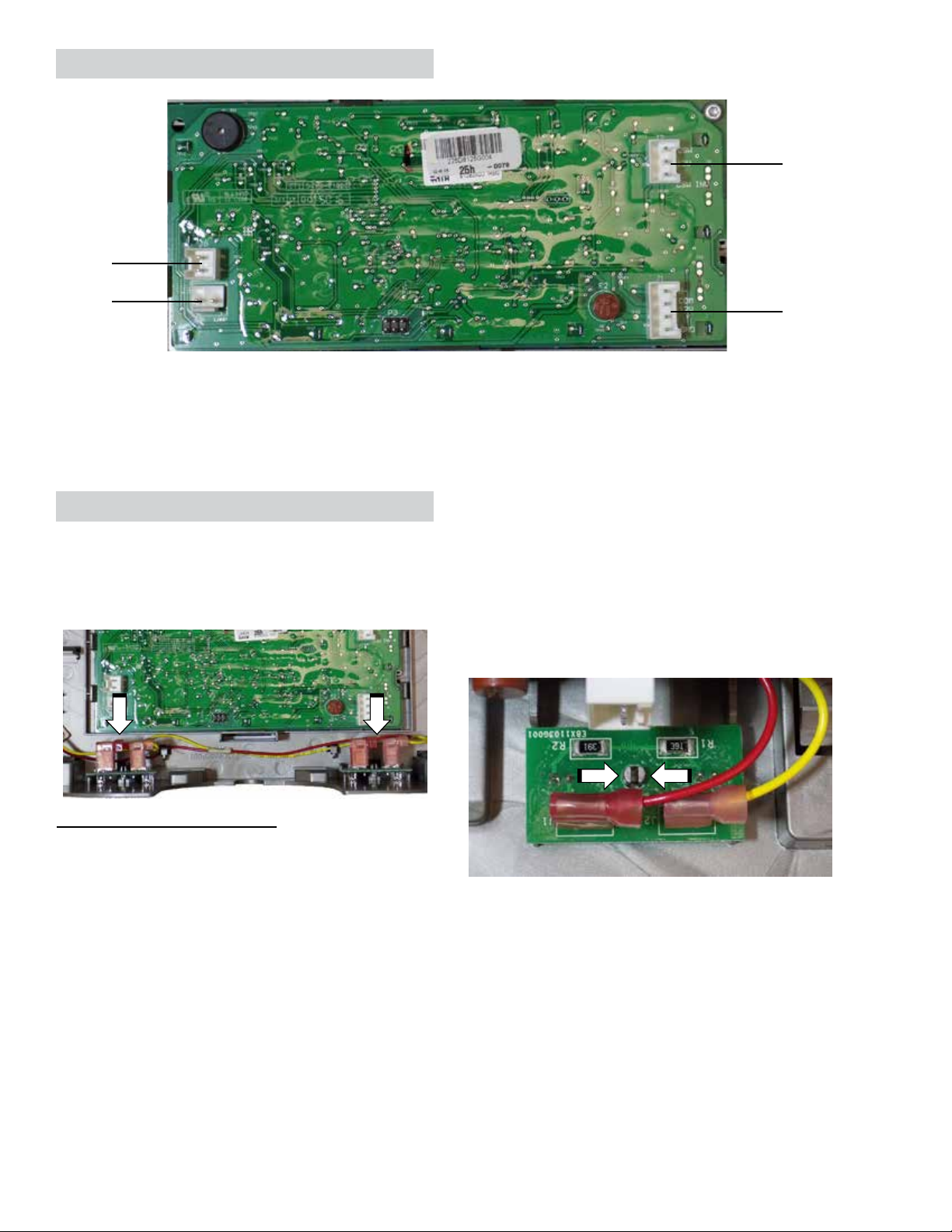
Main Board ...........................................................................................................................69
Main Board Connector Locations .........................................................................................70
Connector Locations (continued) ..........................................................................................71
Machine Compartment .................................................................................................................72
Machine Compartment Cover ...............................................................................................72
Machine Compartment Component Locator ........................................................................72
Isolation Valve.......................................................................................................................73
Drain Tube ............................................................................................................................74
Condenser Fan .....................................................................................................................74
PTCR Relay/Overload ..........................................................................................................76
Capacitor ..............................................................................................................................77
Compressor ..........................................................................................................................77
Drier ......................................................................................................................................78
Condenser ............................................................................................................................78
Refrigeration System ....................................................................................................................79
Replacing Sealed System Components .......................................................................................80
Evacuation and Charging Procedures ..................................................................................80
Lokring ..........................................................................................................................................81
Lokring Rules ........................................................................................................................81
Process Tube Joint ...............................................................................................................81
Drier Joints ...........................................................................................................................82
Evaporator Joints ..................................................................................................................82
Compressor Joints ................................................................................................................83
Condenser Joints ..................................................................................................................83
Service Mode ...............................................................................................................................84
Service Mode Tests ..............................................................................................................85
(Continued next page)
– 7 –
Page 8

Schematic Diagram ......................................................................................................................86
Index .............................................................................................................................................87
– 8 –
Page 9
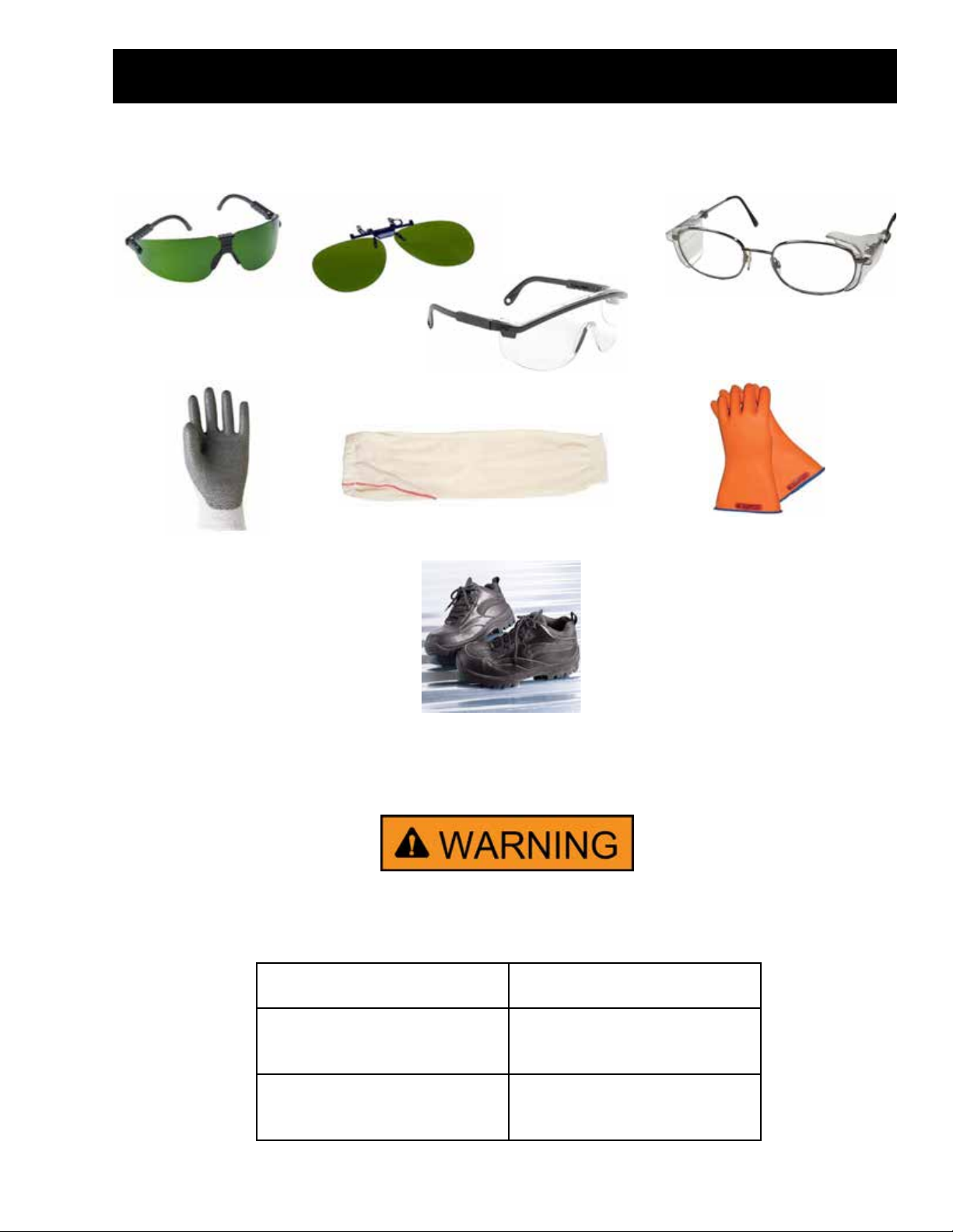
Safety Requirements
GE Factory Service Employees are required to use safety glasses with side shields, safety gloves and
steel toe shoes for all repairs.
Brazing Glasses
Dyneema®Cut Resistant
Glove
Prescription Safety Glasses
Safety Glasses must be
ANSI Z87.1-2003 compliant
Plano Type Safety Glasses
Cut Resistant Sleeve(s)
Electrically Rated Glove and
Dyneema® Cut Resistant Glove
Keeper
Steel Toed Work Boot
Prior to disassembly of the refrigerator to access components, GE
Factory Service technicians are REQUIRED to follow the Lockout /
Tagout (LOTO) 6 Step Process:
Step 1
Plan and Prepare
Step 2
Shut down the appliance
Step 3
Isolate the appliance
Step 4
Apply LOTO device and lock
Step 5
Control (discharge) stored
energy
Step 6
“Try It” verify that the appliance
is locked out
– 9 –
Page 10
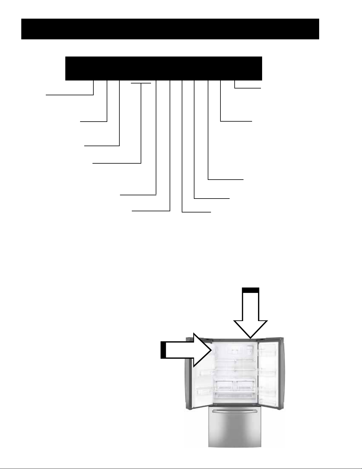
Model Number
Brand
G: GE Appliances
X: Crosley
Conguration
F: Full Depth
Y: Counter Depth
Energy
E: E-Star
Capacity
18: 17.5 Cubic Feet
24: 23.8 Cubic Feet
26: 25.5 Cubic Feet
Nomenclature
G Y E 1 8 J B L A F T S
Feature Pack
J: Deluxe
Finish
B: Black Stainless
G: High Gloss
M: Slate
S: Stainless Steel
Handle Color
B: Black
S: Stainless Steel
W: White
Color
B: Black
D: Black Slate
E: Slate
S: Stainless Steel
T: Black Stainless
W: White
Door Swing
F: French
Engineering Digit
Model Year:
K: 2016
L: 2017
M: 2018
The nomenclature breaks down and explains what the letters and numbers mean in the model number.
Serial Number
The rst two characters of the serial number identify the month and year of manufacture. The letter
designating the year repeats every 12 years.
Example: FL123456S = March, 2018
A – JAN
D – FEB
F – MAR
G – APR
H – MAY
L – JUN
M – JUL
R – AUG
S – SEP
T – OCT
V – NOV
2024 – Z
2023 – V
2022 – T
2021 – S
2020 – R
2019 – M
2018 – L
2017 – H
2016 – G
2015 – F
2014 – D
The Model Serial
ID Tag is located
on the left side
of the refrigerator
compartment.
The Mini Manual is
located under the
right hinge cover.
Z – DEC
2013 – A
– 10 –
Page 11
Specications
WARNING
Electrical Shock Hazard
Death or serious injury can result from failure
to follow these instructions.
• Service by a qualied service technician
only.
• Disconnect power before servicing this
product.
• Reconnect all grounding devices after
service.
• Replace all parts and panels before
operating.
ELECTRICAL SPECIFICATIONS
Max Defrost Control
w/No Door Openings 96 hrs @ 40 min
Evap Defrost Thermostat
Defrost Heater
Fill Tube Heater
Mullion Heater
Recess Heater
95 - 65°F
120 VAC / 33
13 VDC / 136Ω
13 VDC / 24Ω
13 VDC / 100Ω
NO LOAD PERFORMANCE
CONTROL POSITION 0 / 37°F and
AMBIENT TEMPERATURE OF
Fresh Food, °F
Frozen Food, °F
Percent Running Time
65°F 90°F
38 - 40 36 - 38
0 - 1 0 - 2
25 - 50 50 - 80
REFRIGERATION SYSTEM
Minimum Equalized Pressure
@ 70°F 40/45 PSIG
@ 90°F 48/60 PSIG
R134a Refrig. Chg.
18 cu. ft. models:
24 cu. ft. models:
Ω
26 cu. ft. models:
4.00 ounces
4.25 ounces
4.48 ounces
REFRIGERATION DIAGNOSIS
To access the low pressure side of the system,
install a WJ56X61 valve only on the process
tube extending from the compressor case.
Duct Door Heater
Duct Door Motor
Damper Motor
Isolation Valve
Icemaker Valve
Dispenser Valve
Compressor Windings
Ice Blower Fan
Evaporator Fan
Condenser Fan
Auger Motor
Icemaker
120 VAC / 1100Ω
13 VDC / 15Ω
415Ω
120 VAC / 320Ω
120 VAC / 320Ω
120 VAC / 120Ω
120 VAC / 4Ω & 6Ω
6-13 VDC
8-11 VDC
9-10 VDC
120 VAC
120 VAC
– 11 –
Page 12
Installation
WARNING
Refrigerator Location
The product should not be installed in the
following locations:
• Where the temperature will go below 60°F
(16°C) because it will not run often enough to
maintain proper temperatures.
• Where the temperature will go above 100°F
(37°C) because it will not perform properly.
• In a location exposed to water (rain, etc.) or
direct sunlight.
• The refrigerator should be installed on a oor
strong enough to support it fully loaded.
NOTE: Not recommended for installation on
carpeted ooring.
Additional Specications
• 115 volt 60Hz, 15 or 20-amp power supply is
required.
Clearances
These refrigerators should have the following
clearances for ease of installation, proper air
circulation, and enough room for plumbing and
electrical connections.
• Sides: 1/8 inch
• Top (Cabinet/Hinge Cover): 1 inch
• Back: 2 inches
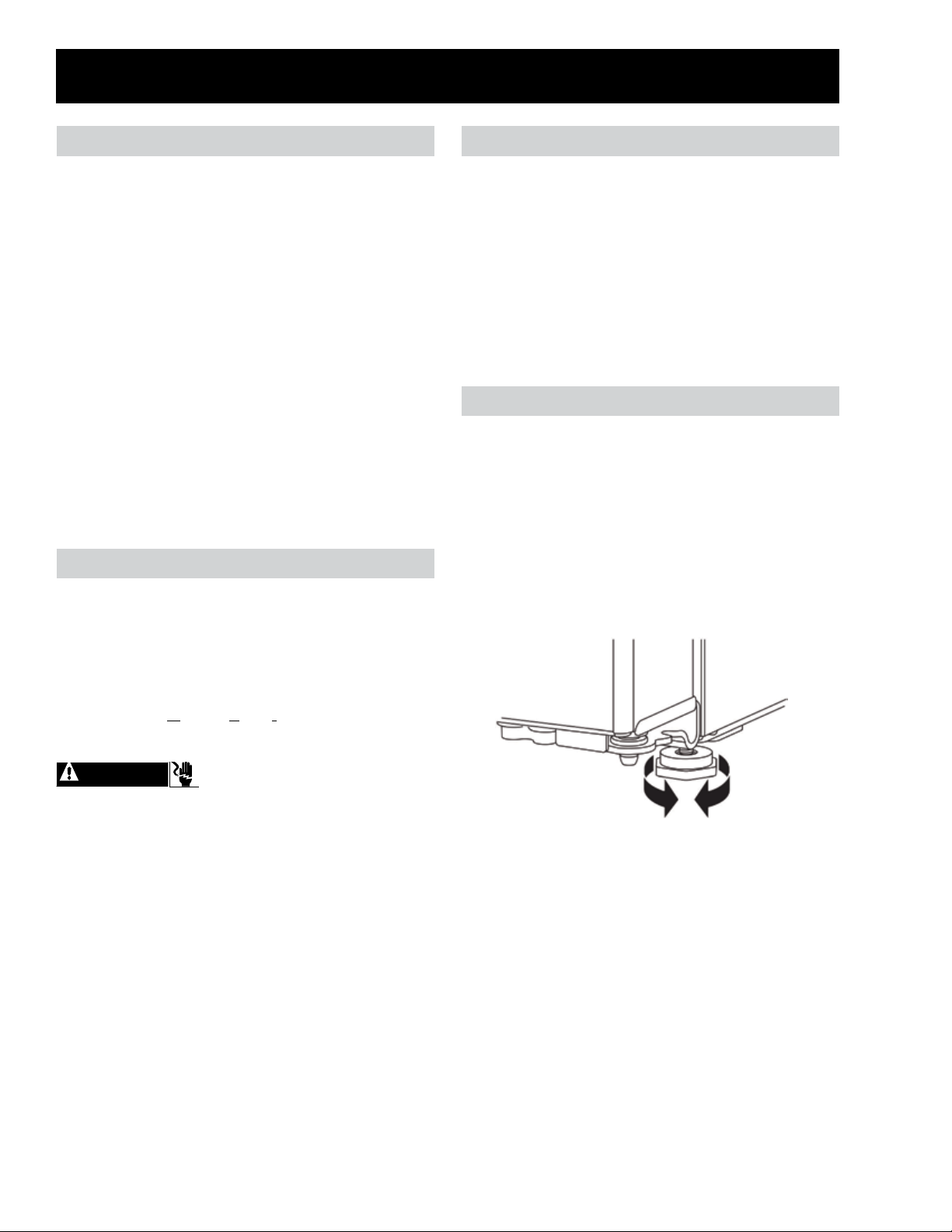
Leveling
The refrigerators have adjustable legs at the front
corners. The leveling legs should be set so the
refrigerator is rmly positioned on the oor and
the front is raised enough that the doors close
easily when opened about halfway.
To Adjust the Leveling Legs:
• Turn the legs clockwise to raise or
counterclockwise to lower the refrigerator.
• An individual properly grounded branch circuit
or circuit breaker is recommended.
NOTE: A GFI (Ground Fault Interrupter) is not
recommended.
Electrical Shock Hazard
• It is required that the refrigerator be plugged
into a grounded 3-prong outlet.
• Ground prong should not be removed.
• Use of a 2-prong adapter or an extension
cord is prohibited.
• Frayed or damaged power cord should
immediately be replaced.
– 12 –
Page 13
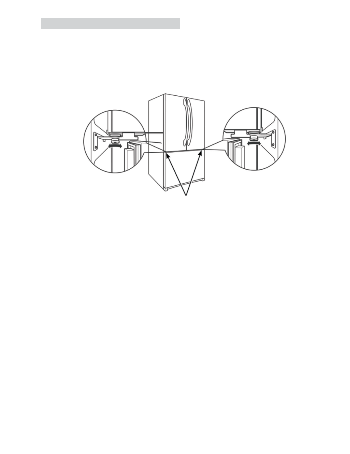
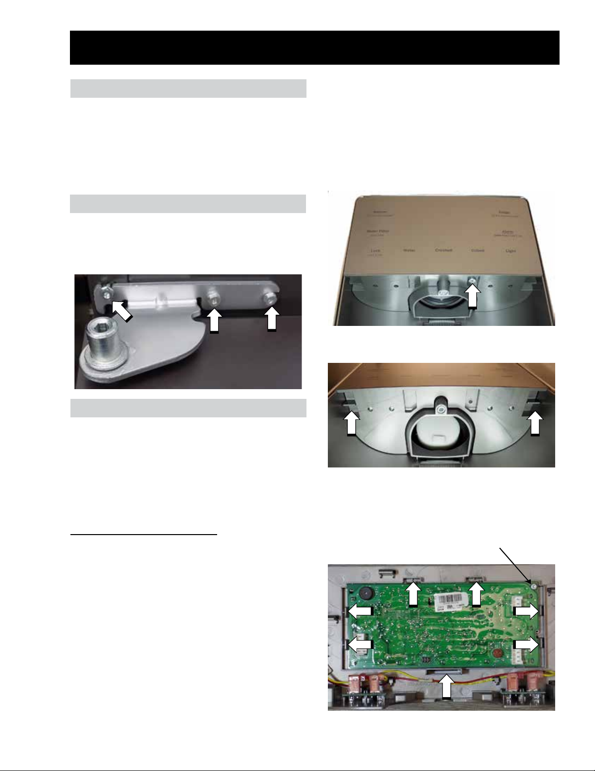
Leveling Refrigerator Doors
The refrigerators door height can be adjusted on both doors. Prior to adjusting the door height, the
refrigerator should be leveled for best results. After the cabinet has been properly leveled, a 1/4-in.
Allen wrench can be used to turn the pin in the bottom hinges of the refrigerator doors.
To Adjust the Door Height:
• Turn the left or right adjustment pin clockwise to raise, or the the adjustment pin counterclockwise to
lower the corresponding door.
Adjustment Pin
Locations
– 13 –
Page 14
Operating Instructions
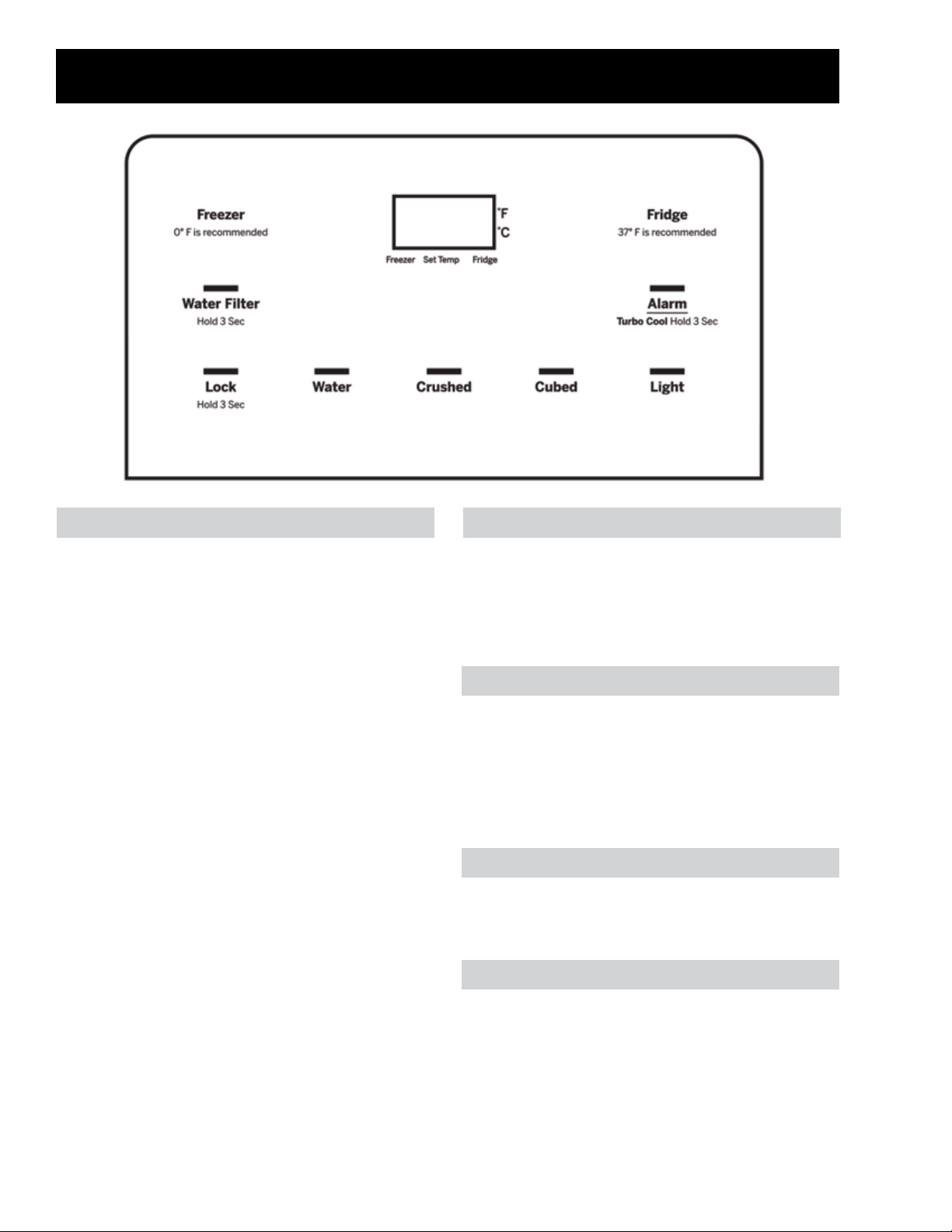
Temperature Control Cooling System O
The temperature display will only show the set
temperatures of the refrigerator.
Default freezer temperature is 0°F. Freezer
temperature can be set to -6°F to 6°F. To change
the temperature setting press the Freezer pad to
display the current set temperature and "wake up"
the display. Then press the Freezer pad again
to increase the set temperature. Once the set
temperature reaches 6°F the next press of the
Freezer pad will cycle the set temperature back
to -6°F.
The default refrigerator temperature is 37°F.
Refrigerator temperature can be set to 34°F
to 44°F. To change the temperature setting,
press the Fridge pad to display the current set
temperature and "wake up" the display. Then
press the Fridge pad again to increase the set
temperature. Once the set temperature reaches
44°F the next press of the Fridge pad will cycle
the set temperature back to 34°F.
To turn o the cooling system, press and hold
both Fridge and Freezer pads until the display
shows OFF. To turn the cooling system on, press
either Fridge or Freezer pads and the display will
show the set temperature.
°F to °C
To change the temperature display between
Fahrenheit and Celsius, press and hold Alarm
and Freezer for 5 seconds. Temperature display
can also be changed using Service Mode Test t14
(see Service Mode Tests in the in the Service
Mode section of this service guide).
Tone Volume
Door alarm volume or the sound in response to
pressing a pad cannot be changed.
Door Alarm
The actual temperature will vary from the set
temperature based on factors such as door
opening, amount of food, defrost cycling and
room temperature.
NOTE: Frequent door openings or a door left
open for periods of time may increase the internal
temperature of the refrigerator compartment
temporarily.
Press the Alarm pad to toggle the door alarm
between ON and OFF states. The alarm will
sound if any door or drawer is left open for more
than two minutes. Once the door or drawer is
closed, the alarm will stop.
– 14 –
Page 15

Lock
Sabbath Mode
The dispenser pads can be locked to prevent
inadvertent presses or to keep children from
making selections/changing settings. Press and
hold the Lock pad for 3 seconds to lock out ice
and water dispenser and all other controls. Press
and hold Lock to unlock the controls.
Turbo Cool
TurboCool™ rapidly cools the refrigerator
compartment in order to more quickly cool foods.
Use TurboCool™ when adding a large amount
of food to the refrigerator compartment, putting
away foods after they have been sitting out at
room temperature, or when putting away warm
leftovers. It can also be used if the refrigerator
has been without power for an extended period.
To set the TurboCool™, press the Alarm pad for
3 seconds. The display will show "tC".
NOTE: The refrigerator temperature cannot
be changed during TurboCool™. The freezer
temperature is not aected during TurboCool™.
When opening the refrigerator door during
TurboCool™, the fans will continue to run if they
have cycled on.
Demo Mode
Demo Mode deactivates compressor, fans, and
defrost heater. All keys on the control panel are
functional. The display will show and blink 888
then switch to displaying the set temperature. To
enter Demo Mode press Lock, Cubed, and Light
pads simultaneously for 5 seconds. To exit Demo
Mode, cycle power to the refrigerator. Demo
Mode can also be entered from Service Mode
Test t1.
Sabbath Mode is designed to eliminate changes
in operations of the refrigerator due to human
interactions. This mode is entered by the
consumer during observance of the Sabbath or
during specic religious holidays.
While in the Sabbath Mode, the appliance will still
operate normally. However, the appliance will not
respond to any consumer actions.
While in the Sabbath Mode, it may be noticed
that the fan is running when the door is opened;
however, this is not a result of any interactions
with the refrigerator. The fan will operate at
random times. The defrost heater will continue to
defrost the appliance and defrost will be activated
on a timer. The defrost heater will not defrost
as a result of door openings or any consumer
actions.
DISPLAYS, ALARMS and LIGHTS: The main
temperature control displays will be deactivated;
therefore, they will not be lit, sound a tone or
operate when touched. Door alarms will be
disabled. Lights will always be on but at a dim
light setting.
To turn on Sabbath Mode, press and hold the
Lock and Light pads until the display shows SA
briey before going blank. Repeat the process to
turn o Sabbath Mode. Temperature set point will
be displayed. Sabbath mode will automatically
exit four days after being entered.
– 15 –
Page 16
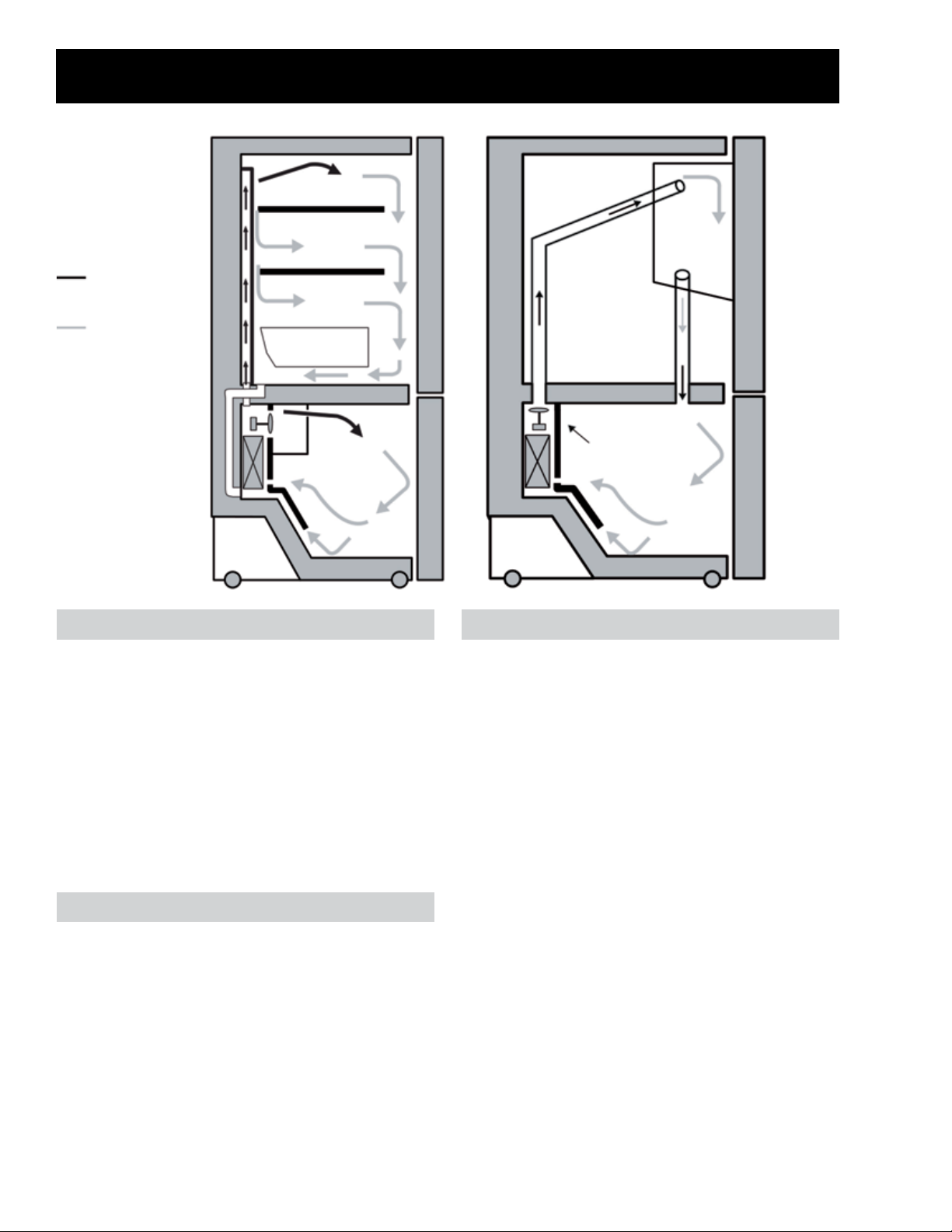
Cold Air
Mixed Air
Air Return To
Evaporator
Air Flow
Refrigerator
Ice Blower Fan
Freezer
Freezer
Refrigerator Air Flow
Cold air is circulated into the compartment by
the evaporator fan. When cooling is required,
the main board opens the damper and turns on
the fan to push cold air from the evaporator up
and out the air tower. The air circulates through
the refrigerator compartment and is pulled back
to the freezer below the evaporator by the way
of the air return passage behind the evaporator.
That warm moist air then gets pull back across
the evaporator coil to extract the heat and
moisture.
Freezer Air Flow
Cold air is circulated in the freezer by the
evaporator fan. When cooling is required, the
main board turns on the fan to circulate cold air
from the evaporator through the evaporator cover.
The air is pulled back to the evaporator through
two ducts built into the bottom of the evaporator
cover. That air then gets pulled back across the
evaporator coil to extract the heat and moisture.
Ice Box Air Flow
Freezer air is circulated into the ice box by the
ice blower fan located in the freezer. The blower
pushes freezer air up and through the top ice
box air duct. Air in the ice box is then forced
out through the return air passage (bottom air
duct) to mix and be circulated with the rest of the
freezer air.
– 16 –
Page 17
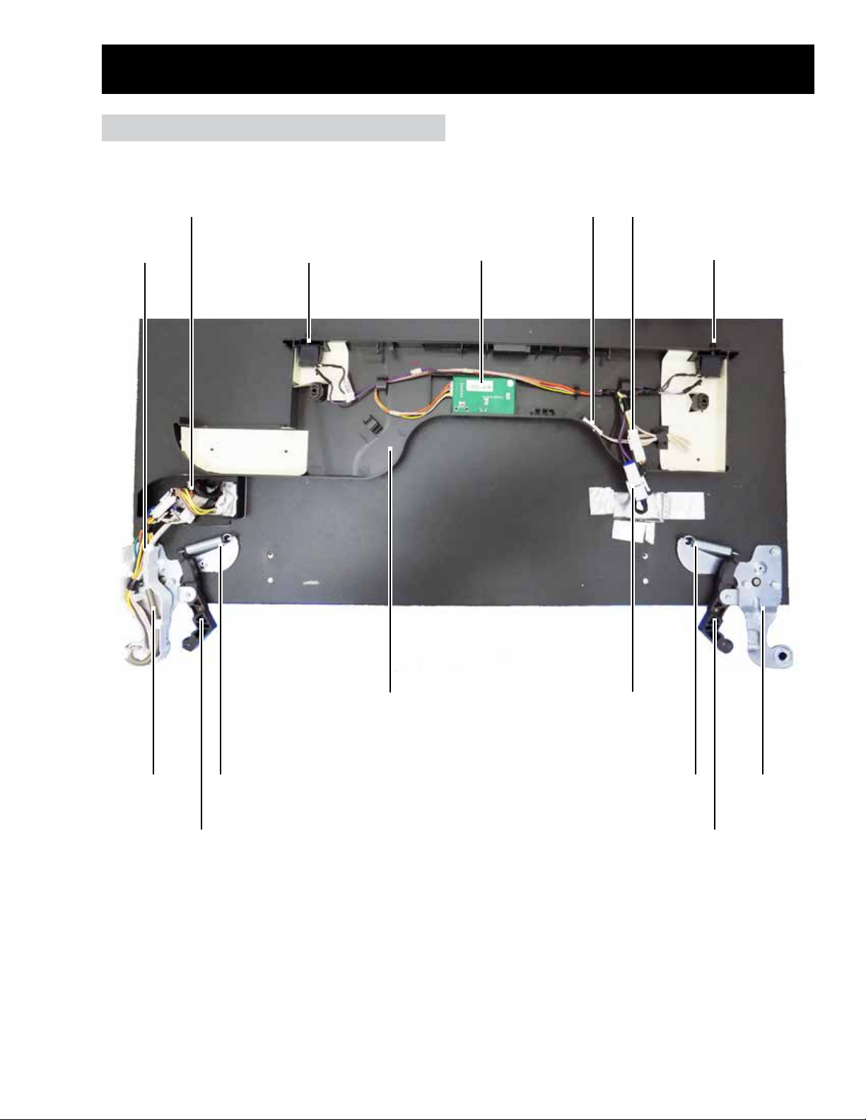
Cabinet Top Components
Cabinet Top
AC and DC Door
Connections
Door Water
Line
Left FF
Door Switch
Thermistor
RJ45 and Humidity
Sensor Board
Ambient
Harness
Connector (DC)
Right FF
Door Switch
Left Door
Hinge
Left Door
Closure
Left Closure
Spring
Top Interface*
– 17 –
Switch Harness
Connector (AC)
Right Closure
Spring
Right Door
*Top interface shown in service position.
Right Door
Hinge
Closure
Page 18
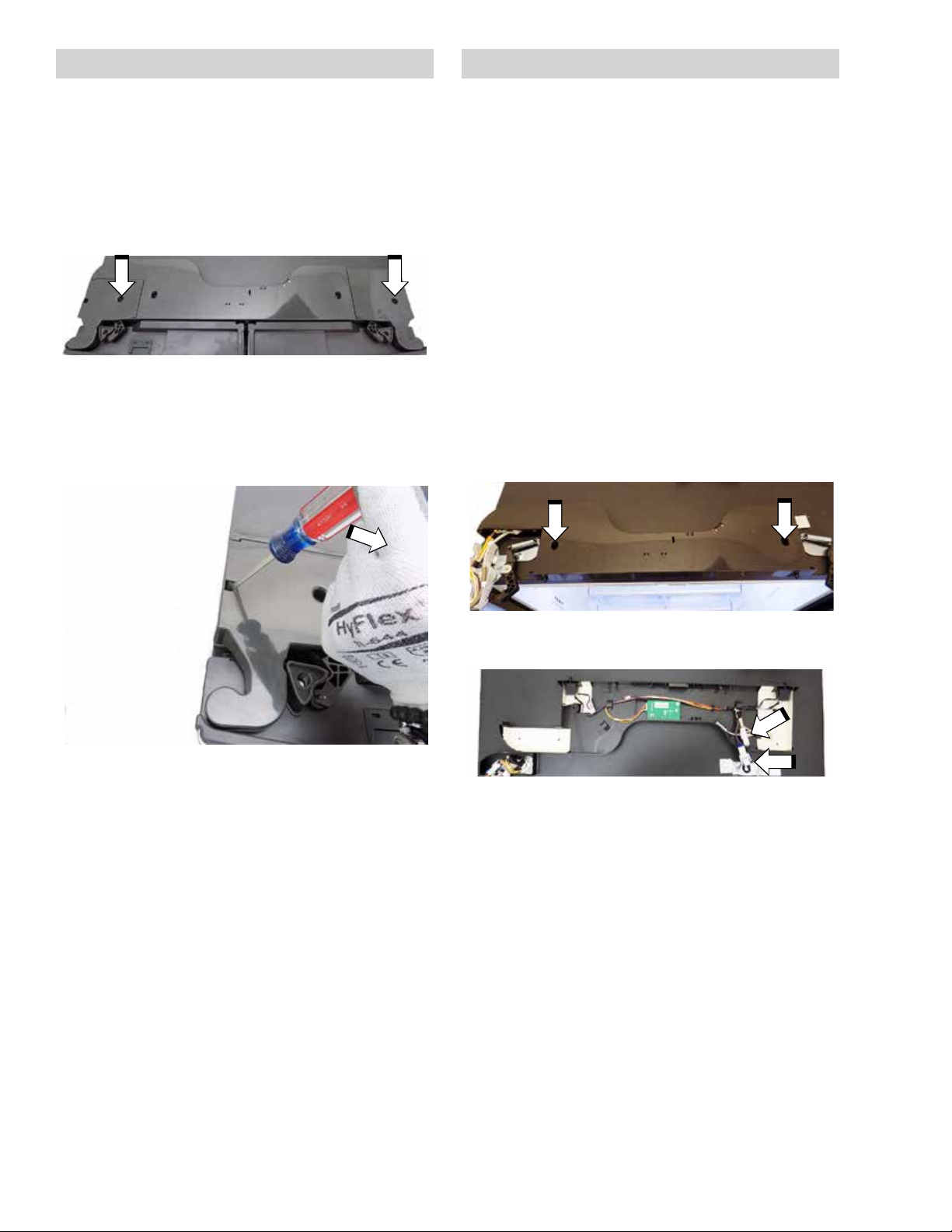
Hinge Covers Top Interface
Left and right hinge covers need to be removed
in order to access the components under the top
interface and to remove the doors.
Hinge Cover Removal
1. Remove one Phillips-head screw for the
desired hinge cover.
2. For the left hinge cover, use a at-blade
screwdriver inserted into the slot on the left
side of the hinge cover and pry to the right
while lifting up on the cover. For the right
hinge cover, proceed to next step.
The top interface houses the refrigerator door
switches, ambient thermistor, switch harness,
DC harness, and RJ45 connector and humidity
sensor board. If the interface needs to be
replaced, all of the components under the
interface will come as part of the assembly. If
a component under the interface needs to
be replaced, that component can be ordered
separately. To service any of the components
under the top interface, the top interface
must be put into the service position (see
the Top Interface callout under Cabinet Top
Components in this section of this service guide).
Top Interface Removal
1. Remove the left and right hinge covers.
2. Remove two Phillips-head screws.
3. Lift the hinge cover up to remove the cover
from the hinge.
3. Flip the top interface back (put into service
position).
4. Disconnect the AC and DC harness
connectors.
5. Remove the interface from the top of the
cabinet.
– 18 –
Page 19
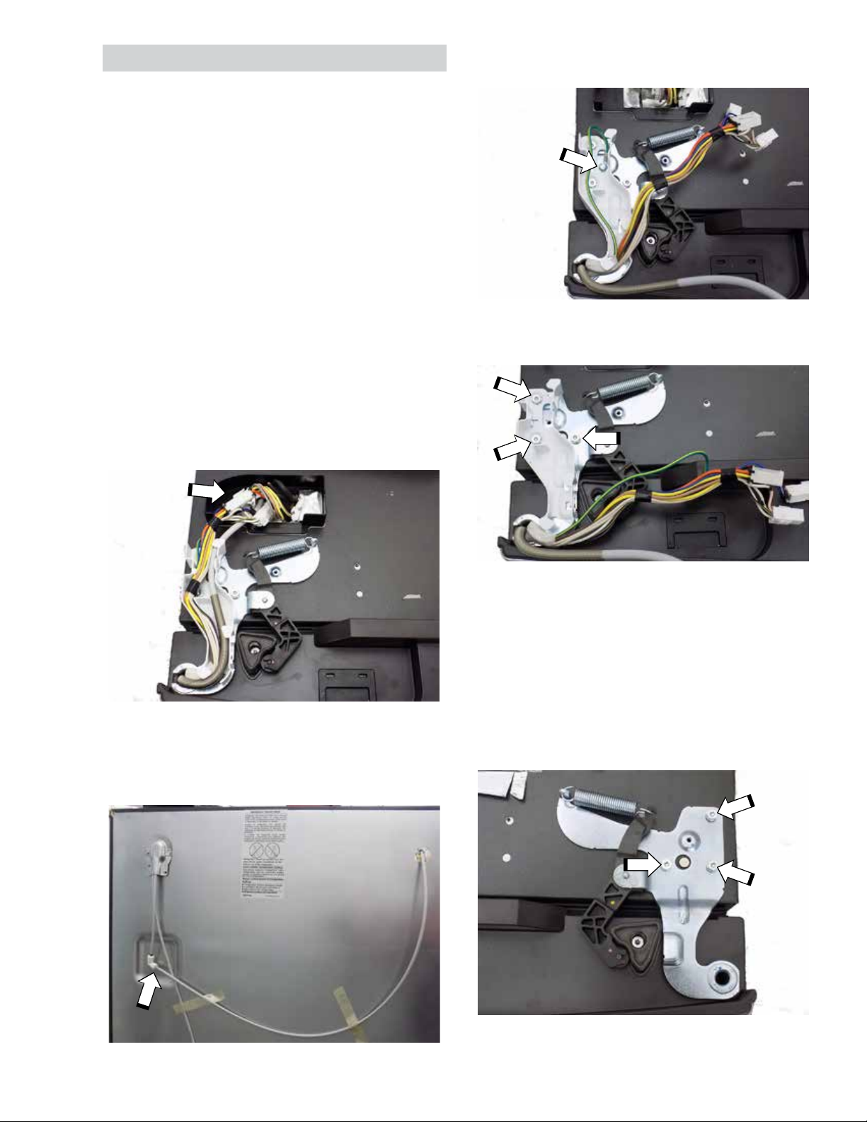
Top Door Hinges
Door hinges incorporate a spring loaded closure.
The closure arms roll over cams mounted to the
top of the refrigerator doors to close the doors
once the doors are a couple inches from closing.
The closure arm and hinge come as an assembly
but the spring can be ordered separately.
Top Left Door Hinge Removal
NOTE: Leave the doors shut during this process
to prevent damage to doors or damage to the
consumer's property.
5. Remove the 1/4-in. hex-head screw mounting
the ground wire to the hinge.
1. Remove the left and right hinge covers.
2. Put the top interface into the service position
(see Top Interface Removal under Top
Interface in this section of this service guide).
3. Disconnect three door wiring connectors
tucked into the top of the cabinet.
4. Disconnect the door water line from the 90°
union located behind the refrigerator and pull
the water line from the cabinet through the
front.
6. Remove three 5/16-in. hex-head screws and
lift the hinge from the cabinet.
Top Right Door Hinge Removal
NOTE: Leave the doors shut during this process
to prevent damage to doors or damage to the
consumer's property.
1. Remove the right hinge cover.
2. Remove three 5/16-in. hex-head screws and
lift the hinge from the cabinet.
– 19 –
Page 20
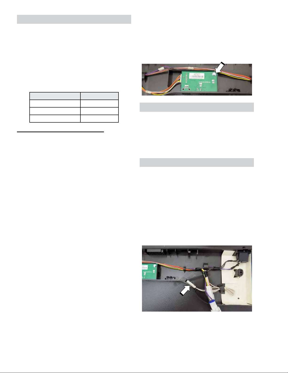
Humidity Sensor Board
The Humidity board is located under the center
of the top interface. The humidity sensor on
the board provides the main board with relative
humidity percentages based on the feedback
voltage (see table below). The feedback voltage
will range between 1 to 4 VDC. The relative
humidity percentage is used to determine the
articulating mullion heater on time (the greater the
humidity, the greater the heater run time).
Relative Humidity Voltage (DC)
20% 1.5 V
50% 2.3 V
80% 3.1 V
Humidity Sensor Board Diagnosing
Before changing the board, ensure the proper
voltages are going to the humidity board.
Humidity sensor voltages can be checked at the
humidity board or main board.
Connector on Humidity Board
• Orange to tan/black: 13 VDC
• Orange to white: 13 VDC
Humidity Sensor Board Removal
1. Place the top interface in the service position
(see Top Interface Removal, under Top
Interface in this section of the service guide).
2. Remove one 1/4 in. hex-head screw and
disconnect the wiring harness.
RJ45 Connector
The RJ45 connector is mounted to the humidity
sensor board inside the top interface and is only
available with the humidity sensor board. The
RJ45 connector is the access point to update
software using a software update module (SUM)
or connect a service diagnostic tool.
Ambient Thermistor
The ambient thermistor is located under the top
interface. The thermistor clips into the backside
of the top interface and is used to determine the
oset temperature of the refrigerator.
• White or tan/black to red/white: 5 VDC
• Yellow to red/white: 1 - 4 VDC
NOTE: 0 or 5 VDC from yellow to red/white
may indicate a bad humidity sensor. Replace the
humidity board if there are no open or shorted
wires to the board.
Connectors on Main Board
• J4 pin 4 (orange) to J4 pin 5 (tan/black): 13
VDC
• J4 pin 4 (orange) to J2 pin 3 (white/silver):
13 VDC
• J5 pin 5 (red/white) to J4 pin 5 (tan/black) or
J2 pin 3 (white/silver): 5 VDC
• J5 pin 5 (red/white) to J5 pin 6 (yellow/
white): 1 - 4 VDC
NOTE: 0 or 5 VDC from J5 pin 5 to J5 pin 6 may
indicate a bad humidity sensor. Replace the
humidity board if there are no open or shorted
wires to the board.
The oset temperature is the temperature the
main control targets. Air temperature inside a
compartment is typically lower than the thermistor
reading due to cabinet thermistors proximity to
cabinet walls. The main control increases the
oset temperature when the ambient temperature
increases.
To access the thermistor, place the top interface
in the service position (see Top Interface
Removal, under Top Interface in this section of
the service guide).
To test or replace the thermistor, follow the steps
in the Thermistors section of this service guide.
– 20 –
Page 21
FF Door Switches
The FF door switches are AC volt switches that
have Normally Closed contacts (N.C.). The
switches are actuated by the top of the doors to
tell the main board to turn the refrigerator LEDs
on or o.
FF Door Switch Diagnosing
When one of the doors are opened, the switch
contacts are closed allowing 120 VAC to travel to
the main board. When closed, the doors engage
the switch to open the switch contacts, breaking
the 120 VAC circuit to the main board.
3. Disconnect the wires from the desired switch.
4. Push in on the plunger of the switch.
Switch Not Pressed (Door or Doors Open)
J7 on Main Board
• Pin 6 (purple/white) to pin 9 (orange): 120
VAC
Switch Pressed (Doors Closed)
J7 on Main Board
• Pin 6 (purple/white) to pin 9 (orange): 0 VAC
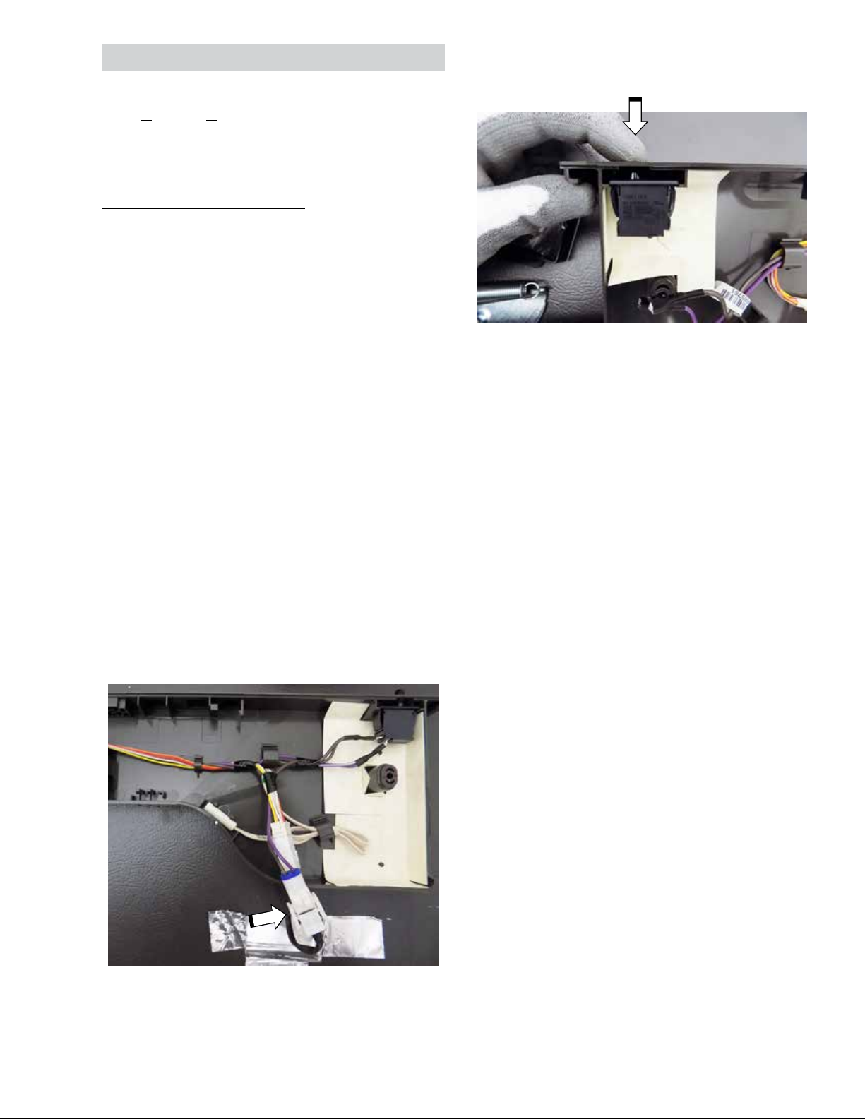
FF Door Switch Removal
1. Place the top interface in the service position
(see Top Interface Removal, under Top
Interface in this section of the service guide).
2. Disconnect the two pin switch harness to
remove power from the switches.
5. With the plunger pressed in, slide the switch
out of the top interface.
– 21 –
Page 22
Door and Drawer Handles
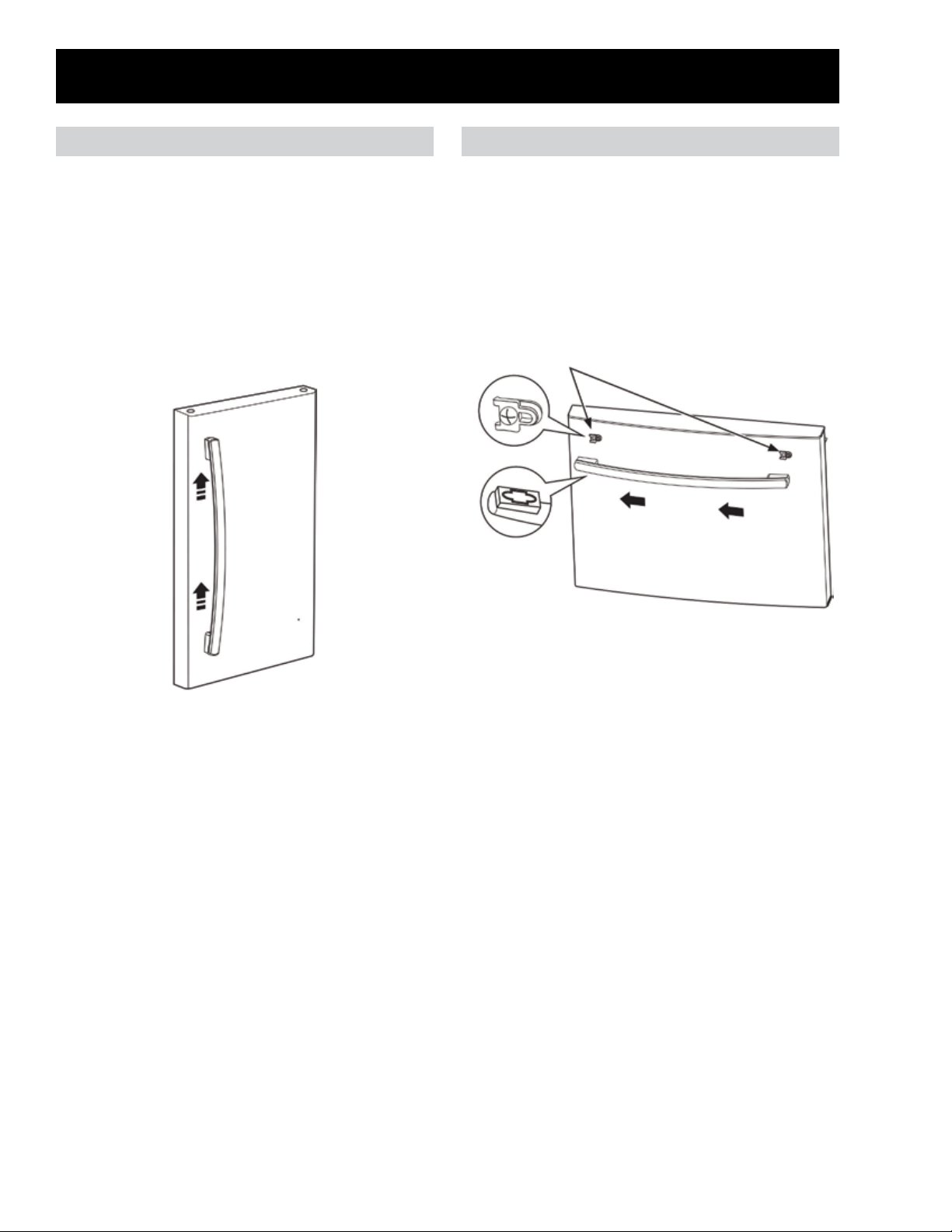
Door Handles Freezer Drawer Handle
Door handles slide and lock into fasteners
mounted to the doors.
Door Handle Removal
1. Slide the handle up to release it from the
mounting fasteners (be aware it takes some
force to release the handle from the mounting
fasteners mounted to the door).
2. Pull the handle away from the door.
The drawer handle slides and locks into fasteners
mounted to the drawer.
Drawer Handle Removal
1. Slide the handle to the left to release it from
the mounting fasteners.
2. Pull the handle away from the door.
Mounting Fasteners
– 22 –
Page 23

Door and Drawer Gaskets
Each door and drawer have a magnetic gasket that creates a positive seal to the front of the steel
cabinet. The magnetic gaskets are secured to the door or drawer by a barbed edge that locks into a
retainer channel.
Gasket Removal and Replacement
1. Starting at any corner, pull the old gasket out of the retaining channel.
2. Soak the new gasket in warm water to make it pliable.
3. Push the barbed edge of the gasket into the retainer channel.
NOTE: A thin coat of petroleum jelly or paran
wax can be applied to the hinge side (sealing
side) of the gaskets to improve closure across the
cabinet.
The door gaskets have a left and right side.
When installing a new gasket, ensure the wider
ends at the top and bottom of the gasket (shown
in the image to the right) are on the mullion side
of the door.
– 23 –
Page 24
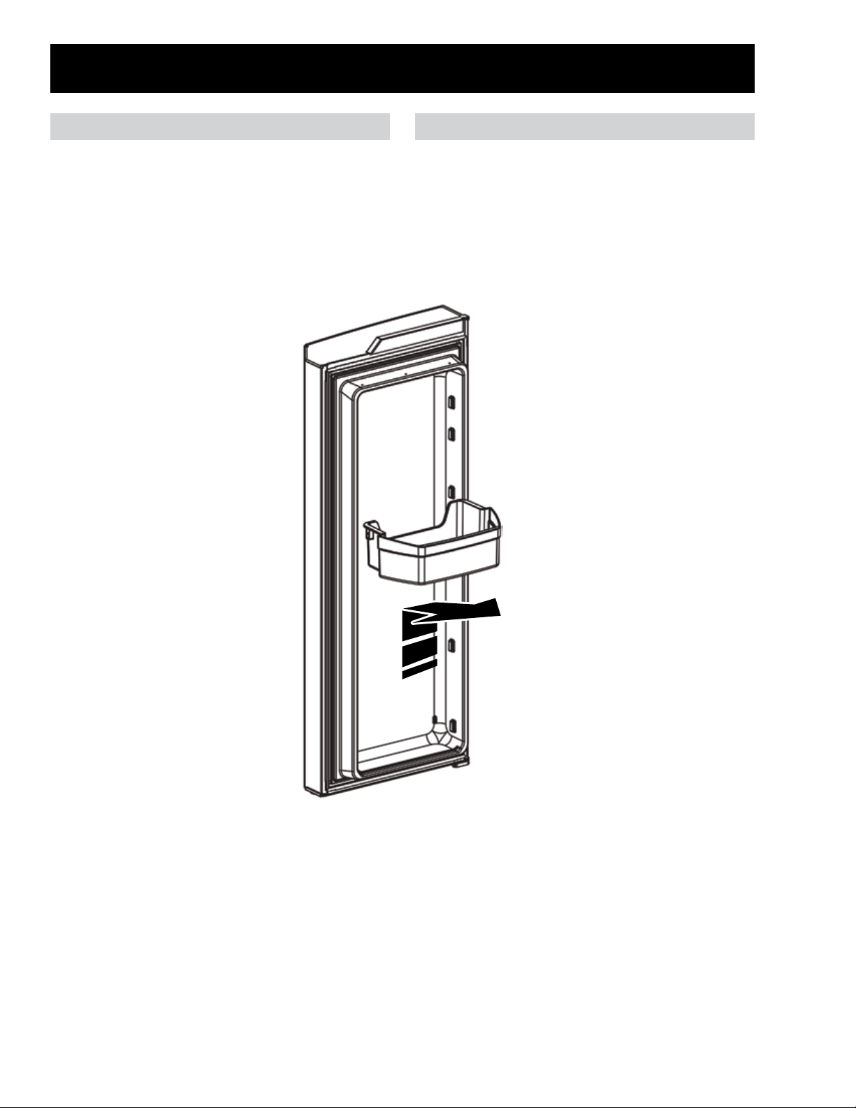
Door Bins
Dispenser (Left) Door Bins Right Door Bins
The left refrigerator door has three removable
door bins. The top and bottom bins can be
interchanged but the middle bin must be used in
the middle location.
Bin Removal
To remove door bins, slide bin up and then pull away from the door.
The right refrigerator door has four removable
door bins. The top three bins can be
interchanged but the bottom bin must be used in
the bottom location.
– 24 –
Page 25
Dispenser Door
Dispenser Door Removal
1. Remove the door bins and ice bucket.
2. Follow Top Left Door Hinge Removal steps,
under Top Door Hinges in the Cabinet Top
section of this service guide.
3. Lift the door o the center hinge.
Left Center Hinge Removal
1. Remove the dispenser door.
2. Remove three screws for the center hinge
using a 5/16-in. socket or T20 Torx-head bit.
J1 on Dispenser Board
• Red to black: 13 VDC
• Red to blue: 13 VDC
Dispenser Board Removal
1. Remove one Phillips-head screw from under
the dispenser board.
2. Pull forward on the backside of the tabs under
the dispenser board.
Dispenser Board
The refrigerator uses a capacitive touch dispenser
board. Through the dispenser board, the user
can change the set temperature, temperature
units (°C or °F) and enter special modes such
as Sabbath, Demo, and Service Mode. The
dispenser board controls the duct door motor and
dispenser LEDs.
Dispenser Board Diagnosing
If the dispenser board is not illuminated, verify
proper voltage is going to the dispenser board. If
voltage is present, replace the dispenser board.
If voltage is not present, check connections at the
door hinge and main board before replacing the
main board. The display LEDs and numerical
segments can be tested by using Service Mode
Test t3.
J2 to J4 on Main Board
• J2 pin 8 (red/silver) to J4 pin 1 (black): 13
VDC
3. Disconnect four wiring connectors.
4. Remove one T15 Torx-head screw and
release seven tabs to remove the board from
the overlay.
Screw
• J2 pin 8 (red/silver) to J4 pin 3 (blue): 13
VDC
– 25 –
Page 26
Dispenser Board Connector Locations
J5
J2
J3
J1: Communication and power from main board
J2: Paddle switch
J3: Duct door motor
J5: Dispenser LEDs
Dispenser LEDs
Two dispenser LEDs boards are located on the
back side of the dispenser control assembly. The
dispenser board turns on the LEDs when the light
button is pressed on the dispenser board.
J1
Dispenser LED Removal
1. Remove the dispenser board panel from the
door.
2. Squeeze the round clip in the middle of the
board and lift up on the LED board.
Dispenser LED Diagnosing
J5 on Dispenser Board
• Red to yellow: 13 VDC
3. Disconnect the wires from the board.
– 26 –
Page 27
Dispenser Recess Components
Duct Door Spring
Duct Door
Door Water Spout
Paddle and
Paddle Switch
Duct Door Motor
*Shown with ice funnel removed.
Drip Tray
– 27 –
Page 28

Ice Funnel
The ice funnel directs cubed and crushed ice from
the door chute to the consumer's glass.
Paddle Switch Diagnosing
• Silver to silver/black: N.C. contacts
• Silver to red: N.O. contacts
Ice Funnel Removal
1. Remove the dispenser board.
2. Remove two 1/4-in. hex-head screws.
3. Pull the funnel forward and turn the backside
of the funnel clockwise.
Switch not pressed (home position)
• Silver to silver/black: 0 VDC
• Silver to red: 13 VDC
Switch pressed
• Silver to silver/black: 13 VDC
• Silver to red: 0 VDC
Paddle Switch Removal
1. Remove the dispenser board.
2. Remove the ice funnel.
3. Using a at-blade screwdriver, gently pry the
tabs of the paddle out of the recess.
4. Lift the door water spout from the funnel.
Paddle Switch
Mounted to the backside of the paddle is a threeway micro switch. The switch tells the dispenser
board when the paddle is being pressed or when
it is in the home position.
4. Pull the top of the paddle away from the
recess then lift up on the paddle.
5. Remove the switch and wiring from the
backside of the paddle, making note of the
wiring routing for reinstallation.
– 28 –
Page 29

Duct Door Motor Duct Door
The duct door motor is a DC motor used to open
the duct door. The motor receives 13 VDC from
the dispenser board when the paddle switch is
activated and 2.5 VDC to hold the door open for 5
seconds once the paddle is released.
Duct Door Motor Diagnosing
The motor has a resistance of 15 ohms. To verify
duct door motor operation, activate the paddle
switch or use Service Mode Test t5 and verify
voltage at the J5 connector on the dispenser
board. Test t5 will operate the motor for 10
seconds.
Paddle Switch Pressed
• J5 black to J5 black/silver: 13 VDC
Duct Door Motor Removal
1. Remove the dispenser board.
2. Remove the ice funnel.
The duct door is used to keep ambient air from
entering the ice box. When ice is called for, the
duct door motor turns to open the duct door. The
duct door spring then return the duct door to the
closed position within 5 seconds of releasing the
paddle. If the door is not fully closing, check the
duct door spring to make sure it is not broken or
installed incorrectly.
Spring
3. Use a at-blade screwdriver to pry the duct
door motor and duct door away from the
recess.
4. Pull the duct door o the shaft of the duct
door motor.
Duct Door Removal
• Follow duct door motor removal steps.
Recess Heater
Foamed into the dispenser door is a 100-ohm
DC heater designed to keep the recess from
condensating. The heater is in parallel with the
ll tube heater, both are controlled by the main
board.
Recess Heater Diagnosing
The recess heater can be operated using Service
Mode Test t6. Test t6 will operate the heater for
60 seconds.
J2 to J5 on Main Board
• J2 pin 8 (red/silver) to J5 pin 3 (violet/white):
13 VDC
– 29 –
Page 30

Articulating Mullion
The articulating mullion contains a DC heater to
keep the mullion from forming condensation. The
heater ON time is based on the relative humidity
percentage calculated by the main board. The
calculation is based on the feedback provided by
the humidity sensor. The top of the articulating
mullion engages with the mullion striker to open
and close the mullion. When the mullion is in the
closed position, the mullion provides the mating
surface for the right door. If the articulating
mullion does not make contact with the mullion
striker, the dispenser door will need to be raised.
2. Remove two Phillips-head screws securing
the center mounting plate to the door (heater
connections are behind this plate).
Articulating Mullion (shown
in closed position)
Articulating Mullion Diagnosing
The heater in the mullion has a resistance of 24
ohms.
3. Slide the mullion up o the door.
J2 on Main Board
• Pin 8 (red/silver) to pin 6 (black/yellow): 13
VDC
Articulating Mullion Removal
1. Open the dispenser door and ip the
articulating mullion to the closed position.
4. Disconnect the two pin connector.
– 30 –
Page 31

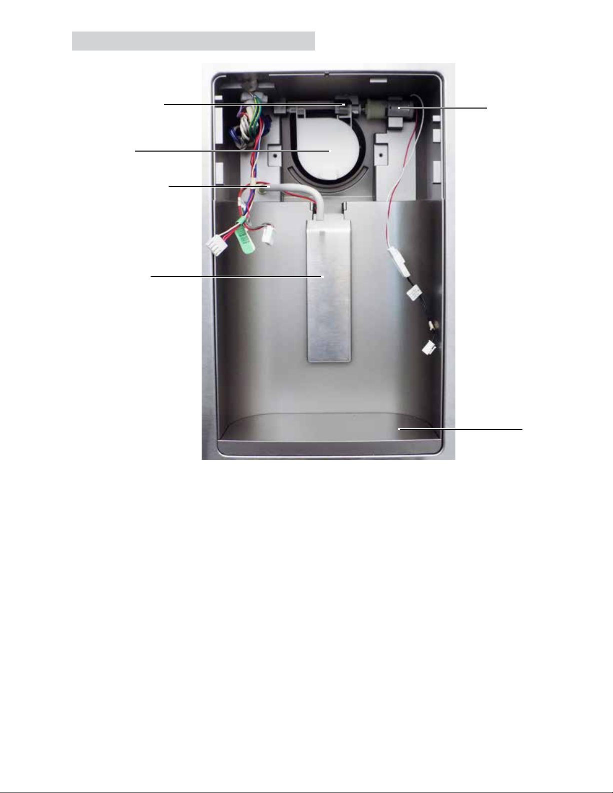
Water Tank Cover
The water tank cover is located behind the
lower door bin of the dispenser door. The cover
conceals the water tank and dual valve.
Water Tank Cover Removal
1. Remove the lower door bin.
2. Remove three Phillips-head screws.
3. Pull the clip from the collar of the dispenser
valve.
Water Tank
The coil-style water tank is located inside the
bottom of the dispenser door.
Water Tank Removal
1. Remove the water tank cover.
2. Remove two Phillips-head screws.
Collar
4. Push in on the collar of the dispenser valve
while pulling on the tank tubing to remove the
tubing from the valve.
5. Push in on the collar of the door water line
union while pulling on the tank tubing to
remove the tank tubing from the union.
Clip
Dual Valve
The dual valve is located behind the water tank
cover of the dispenser door. One solenoid opens
the dispenser side of the valve and the other
solenoid opens the icemaker side of the valve.
Dual Valve Diagnosing
The main board supplies voltage to the dual valve
and isolation valve. To test the dispenser side
of the dual valve, engage the dispenser paddle
switch while both door switches are engaged.
Voltage checks can be performed at the dual
valve connector or main board. If the dual valve
is getting voltage but no water, ensure isolation
valve is working.
Dispenser Valve:
• Yellow - orange: 120 VAC
(Continued next page)
– 31 –
Page 32

Main Board
• J7 pin 3 (yellow) - J7 pin 9 (orange): 120
VAC
The icemaker supplies the voltage to the
icemaker valve and isolation valve. To test the
icemaker valve, cycle the icemaker. Voltage
checks can be performed at the dual valve
connector. If the dual valve is getting voltage but
no water, ensure isolation valve is working.
Icemaker Valve
• White - orange: 120 VAC
Dual Valve Removal
1. Remove the water tank cover.
2. Pull the clips from the collars of the water
valve.
Diodes
The isolation valve is shared between the
dispenser and icemaker valves circuits; diodes
are used to prevent voltage from the main board
going to the valve not intended to be energized.
The diodes are part of the dual valve harness
attached to the dual valve solenoids. Should one
of the diodes fail, replace the dual valve.
Collar
Clip
Collar
3. Push in on the collars on the water valve
while pulling the water lines out to remove the
lines from the dual valve.
4. Remove two Phillips-head screws.
Diodes
Diode Diagnosing
When a diode fails, it can either open or short.
If one of the diodes should open, the isolation
valve will not receive power for one of the water
operations. If one of the diodes should short,
one of the water operations will cause both the
icemaker and dispenser valve to activate.
5. Disconnect the 4-pin water valve connector.
– 32 –
Page 33

Ice Box Components
Ice Box Compartment
Icemaker
On/O Switch
Icemaker
Icemaker
Fill Cup
Upper Port Gasket
Collar Port
Feeler Arm
Icemaker
Status LED
Ice Box Thermistor
Icemaker Access
Cover
Lower Port Gasket
Auger Motor
– 33 –
Page 34

Ice Box Door Ice Box Port Gaskets
The ice box door comes as an assembly to
include the ice box door gasket, door latch, door
latch cover, and ice box door. The door must be
replaced as an assembly.
Ice Box Door Removal
1. Remove two T15 Torx-head screws securing
the top ice box door hinge to the door.
2. Release the door latch and lift the door o the
lower ice box door hinge.
The dispenser door has two ice box port gaskets.
The gaskets are used to seal the ice box inlet and
outlet air ports to the inlet and return air ports of
the cabinet when the dispenser door is closed.
Ice Box Port Gasket Removal
1. Using a at-blade screwdriver, pry the gasket
port away from the door.
Ice Bucket
The ice bucket comes as an assembly to include
the crusher, fork, auger, and bucket. The bucket
must be replaced as an assembly. Turning the
auger in the bucket clockwise produces crushed
ice, turning the auger counterclockwise releases
cubed ice.
Ice Bucket Removal
1. Open the ice box door.
2. Lift up on the handle of the bucket and pull
the bucket out of the ice box.
Handle
2. Pull the gasket out of the gasket port.
– 34 –
Page 35

Collar Port Icemaker Access Cover
The collar port redirects the air going into the ice
box for optimum ice production.
Collar Port Removal
1. Remove the top ice port gasket from the door.
2. Push up and in on the tab located inside the
port of the door (viewed from outside the
door).
The access cover conceals the electrical
connections for the icemaker and auger motor
as well as provide the ice box thermistor with a
mounting location.
Icemaker Access Cover Removal
1. Remove the ice bucket.
2. Remove three Phillips-head screws.
3. Unclip the thermistor from the backside of the
cover.
3. Remove the ice bucket.
4. Pull collar port out from inside the door.
Ice Box Thermistor
The main board uses the thermistor to monitor
ice box temperatures and regulate the icemaker
blower fan. To access the thermistor, remove the
icemaker access cover.
To test or replace the thermistor, follow the
steps under Thermistor Replacement in the
Thermistors section of this service guide.
– 35 –
Page 36

Auger Motor Icemaker
The auger motor is a reversible AC motor. When
the auger motor turns the auger in the bucket
clockwise crushed ice is produced. When
the auger motor turns the auger in the bucket
counterclockwise cubed ice is released. During
cubed operation, the main board sends 120 VAC
on J7 pin 2 to the motor to activate a reversing
relay inside the motor.
Auger Motor Diagnosing
Operating voltage for the auger motor can be
checked at the auger motor connector or at J7 on
the main board.
J7 on Main Board (Cubed)
• Pin 1 (tan) to pin 9 (orange): 120 VAC
• Pin 2 (grey) to pin 9 (orange): 120 VAC
J7 on Main Board (Crushed)
• Pin 1 (tan) to pin 9 (orange): 120 VAC
The refrigerator uses an electronic icemaker. The
toggle switch on the front of the icemaker turns
the icemaker ON/OFF. The green LED on the
front of the icemaker indicates that there is power
to the icemaker and the icemaker is turned on.
The icemaker will produce seven cubes per
cycle approximately 100 to 130 cubes in a 24hour period, depending on freezer compartment
temperature, room temperature, number of door
openings and other use conditions. The icemaker
will ll with water when the mold body thermistor
of the icemaker cools to 15°F (-10°C). A newly
installed refrigerator may take 12 to 24 hours
to begin making ice cubes. When the bin lls
to the level of the feeler arm (keeping the feeler
arm in the back position), the icemaker will stop
producing ice.
On/O Switch
Feeler Arm
• Pin 2 (grey) to pin 9 (orange): 0 VAC
Auger Motor Removal
1. Remove the ice bucket.
2. Remove the icemaker access cover.
3. Remove two Phillips-head screws.
4. Disconnect the 3-pin connector.
Green Power LED
Normal Operation
• To hear a buzzing sound each time the
icemaker lls with water.
• For several cubes to be joined together.
• If ice is not used frequently, old ice cubes will
become cloudy, taste stale and shrink.
– 36 –
(Continued next page)
Page 37

Icemaker Diagnosing
To manually cycle the icemaker, turn the icemaker
o for 30 seconds then turn it back on and press
in and release the feeler arm of the icemaker
three times within 5 seconds. When the icemaker
calls for water it will deliver 120 VAC to the water
valves and to J18 on the main board. The door
switches do not need to be engaged in order to
cycle the icemaker.
Fill Tube
The icemaker ll tube is not removable. The
tube is foamed into the dispenser door (left
door). Should the tube be damaged or need to
be replaced, the dispenser door will need to be
replaced.
Fill Tube Heater
J18 and J7 on Main Board (During Fill)
• J18 (white) - J7 pin 9 (orange): 120 VAC
Icemaker Valve (During Fill)
• White - orange: 120 VAC
Isolation Valve Connector (During Fill)
• Yellow/black - orange: 60 VAC*
*As a result of the diodes in the isolation valve
circuit, only 60 VAC will be read from a voltmeter
when checking for voltage going to the isolation
valve.
Icemaker Removal
1. Remove the ice bucket.
2. Remove the icemaker access cover.
3. Remove two 1/4-in. hex-head screws.
Foamed into the dispenser door is a 136-ohm
heater designed to keep the ll tube from freezing.
The heater is in parallel with the recess heater,
both are controlled by the main board.
Fill Tube Heater Diagnosing
The ll tube heater can be operated using Service
Mode Test t6. Test t6 will operate the heater for
60 seconds.
J2 to J5 on Main Board
• J2 pin 8 (red/silver) to J5 pin 3 (violet/white):
13 VDC
4. Disconnect the icemaker harness connector.
– 37 –
Page 38

Right Door
Right Door Removal
1. Remove the door bins.
2. Follow Top Left Door Hinge Removal steps,
under Top Door Hinges in the Cabinet Top
section of this service guide.
3. Lift the door o the center hinge.
Right Center Hinge Removal
1. Remove the right door.
2. Remove three screws for the center hinge
using a 5/16-in. socket or T20 Torx-head bit.
– 38 –
Page 39

Door - Top
Door - Top Component Locator
Closure
Top Door
Bumper
*The door harness and water line will pass through the top hinge bushing on dispenser doors.
Top Door Bumper
Top Door Bumper Removal
1. Remove the door gasket.
2. Push down on the door bumper to remove it
from the door.
Top Hinge Bushing
The top hinge inserts into the top bushing. If
worn, the bushing can be replaced.
Top Hinge Bushing Removal
1. For the side needing to be removed, follow
Top Left Door Hinge Removal steps, under
Top Door Hinges in the Cabinet Top section
of this service guide.
Cam
Top Hinge
Bushing*
Closure Cam
The spring-loaded closure from the hinge rolls
across the closure cam to close the door when
the door is a couple inches from closing.
Closure Cam Removal
1. For the side needing to be removed, follow
Top Left Door Hinge Removal steps, under
Top Door Hinges in the Cabinet Top section
of this service guide.
2. Remove one T20 Torx head screw.
2. Using a putty-knife of at-blade screwdriver
pry the bushing from the top of the door.
– 39 –
Page 40

Door - Bottom
Door - Bottom Component Locator
Bottom Hinge
Bushing
Door Stop
Bottom Door Bumper
Bottom Door Bumper Removal
1. Remove the door gasket.
2. Rotate the bumper up.
Bottom Door
Bumper
Bottom Hinge Bushing
The center hinge pin inserts into the bottom
bushing. If worn, the bushing can be replaced.
Bottom Hinge Bushing Removal
• Follow the Door Stop Removal steps, under
Door Stop in the next section.
3. Using a small at-blade screwdriver, pry the
bumper from the bottom of the door.
Door Stop
The door stop prevents the door from opening
too far. When the door is fully opened the stop
makes contact with the outside of the center
hinge, preventing the door handle from coming
in contact with the cabinetry. Should the door be
travelling past the stop position, check for a bent
or broken door stop, or a center hinge pin that
has been raised too high.
Door Stop Removal
1. For the side needing to be removed, follow
Top Left Door Hinge Removal steps, under
Top Door Hinges in the Cabinet Top section
of this service guide.
2. Lift the door o the center hinge.
(Continued next page)
– 40 –
Page 41

3. Remove two T20 Torx-head screws.
4. Pull the door stop and bushing out of the door.
5. The bushing is keyed, turn the bushing to
align the tabs of the bushing with the slots in
the door stop.
Slots
Tab
Tab
6. Pull the bushing out of the door stop.
NOTE: Like the door stop, the door is also keyed.
Once a bushing is reinstalled into a door stop the
tabs of the bushing will need to be aligned with
the slots in the door to reinstall the door stop.
– 41 –
Page 42

Water Filter Cartridges
The water lter cartridge is located in the right rear upper corner of the refrigerator. There will be two
dierent style of cartridges depending on the model size and when the models were manufactured.
The 26 cu. ft. models use the XWF style lter. The 18 and 24 cu. ft. model use MWFP style lters until
they transition to XWF lters mid-2018.
MWFPXWF
When to Replace the Filter
There is a replacement indicator light for the water lter cartridge on the dispenser. A red light will start
blinking when the lter needs to be replaced soon. The lter cartridge should be replaced when the
replacement indicator light turns red or if the ow of water to the dispenser or icemaker decreases or if
the ice cubes are getting hollow or small. The indicator should turn red after 6 months or 170 gallons
have been dispensed.
– 42 –
Page 43

Water Filter (MFWP) Water Filter (XWP)
MWFP Filter Cartridge Removal
• Slowly turn the lter to the left. Do not pull
down on the cartridge.
MWFP Filter Cartridge Installation
1. Fill the replacement cartridge with water
from the tap to allow for better ow from the
dispenser immediately after installation.
2. Line up the arrow on the cartridge and the
manifold. Place the top of the new cartridge
up inside the holder. Do not push it up into
the manifold.
3. Slowly turn it to the
right until the lter
cartridge stops. DO NOT
OVERTIGHTEN. The
cartridge will move about a
1/2 turn.
4. Run water from the dispenser for 1-1/2
gallons (about three minutes) to clear the
system and prevent sputtering.
5. Press and hold the Water Filter pad on the
dispenser board for three seconds.
NOTE: Remove the water lter to immediately
stop any water leak from the Icemaker/Dispenser
system. The water lter manifold acts as a cut-o
valve when the lter is removed and will prevent
further leaking.
XWF Filter Cartridge Removal
1. Open the lter cartridge housing by squeezing
two front tabs and gently pull the cover down.
2. Rotate the lter down.
3. Grasp the lter and slowly turn it
counterclockwise about a 1/4 turn. The lter
should automatically release itself when it has
been rotated far enough to the left.
Filter Cartridge Installation
1. Follow XWF Filter
Cartridge Removal
steps.
2. Line the ports on the
lter with the ports of
the manifold, and gently
insert the lter.
3. Slowly turn the lter
to the right until it
stops. DO NOT
OVERTIGHTEN. The
lter will move about a
1/4 turn (90 degrees),
until the arrow on the
lter aligns with the
arrow on the manifold.
4. Slowly push the lter up
into the clips. Close the
lter cover by pushing
upwards on the cover
until the tabs lock into
place.
5. Run water from the dispenser for 2 gallons
(about ve minutes) to clear the system and
prevent sputtering. If water is not owing,
check to make sure the lter has been fully
rotated to the right.
6. Press and hold the Water Filter pad on the
dispenser board for three seconds.
NOTE: Remove the water lter to immediately
stop any water leak from the Icemaker/Dispenser
system. The water lter manifold acts as a cut-o
valve when the lter is removed and will prevent
further leaking.
– 43 –
Page 44

Refrigerator Compartment
Refrigerator Component Locator
Mullion Striker
Upper LED
FF Thermistor
Ice Box Air Inlet Duct
Water Filter*
Adjustable
Shelves (x4)
Ice Box
Return Air Duct
Center Track
Air Tower
Climate Zone
Slides (x3)
Lower LED (x2)
Climate Zone
Vegetable Pans (x2)
Climate Zone
Meat Pan
*MWFP style lter is shown. The 26 cu. ft. models will use XWF style lter. The 18 and 24 cu. ft. model
will transition to XWF lters mid-2018.
– 44 –
Page 45

Adjustable Shelves Pan Covers
The refrigerator has four adjustable shelves.
Each shelf can be raised or lowered but cannot
be moved right to left or vise-versa because the
center is the only location of a shelving track.
Instead of outer tracks, the shelves use the liner
to support the liner side of each shelf.
Adjustable Shelf Removal
1. Tilt the front of the shelf up.
2. Lift the rear of the shelf up to disengage the
top hook of the shelf from the center track.
3. Pull the shelf out from the refrigerator.
The refrigerator has two pan covers. The two
vegetable climate zone pans slide in and out of
the upper pan cover. The lower meat climate
zone pan slides in and out of the lower pan cover.
Each pan cover has a climate zone slide to adjust
the air ow into the pans. Moving the upper
climate zone slides to the left and the lower slide
to the right increases the air ow.
Open
Close
Upper Climate Control Slides
CloseOpen
Lower Climate Control Slide
Climate Zone Pans
The refrigerator has three pans; each pan has a
climate zone slide associated with it to increase
or decrease airow into the pans. The top two
are vegetable pans and the lower full width pan is
the meat pan.
Climate Zone Pan Removal
1. Slide the pans out to the stop position.
2. Lift the front of the desired pan up and out of
the pan cover.
Each side of the pan covers are supported by
two studs which are screwed into the liner (18 cu.
ft. models) or one stud and the rear indent in the
liner (24 and 26 cu. ft. models).
Pan Cover Removal
1. For the upper pan cover, remove both
vegetable pans. For the lower pan cover,
remove all pans.
2. Lift up on the front of the upper pan cover and
pull the cover out. Repeat the process for the
lower cover.
– 45 –
Page 46

Mullion Striker
The top of the articulating mullion engages with
the mullion striker to open and close the mullion.
When the articulating mullion does not make
contact with the mullion striker, the dispenser
door may need to be raised.
Mullion Striker Removal
• Remove two Phillips-head screws.
Upper LED Housing
Upper LED Diagnosing
• When the LED housing fails completely, the
lower LED boards will still work.
Main Board with Door Open
• J4 pin 2 (red/yellow) - J5 pin 1 (pink/black):
4 - 13 VDC *(see NOTE)
Two Pin Connector at Cabinet
• Red - black: 4 - 13 VDC *(see NOTE)
NOTE: When one or both of the refrigerator
doors are opened, the main board delivers 4 VDC
to the LED housing and gradually increases the
voltage to 13 VDC for full brightness.
Upper LED Removal
1. Using two ngers, push forward on the
indicated areas to release the rear tabs of the
shield to lower the rear of the shield.
The main source of light comes from the upper
LED housing. Strip LEDs are connected to
the outside of the housing while the inside of
the housing holds the foam block which the
refrigerator (FF) thermistor slides into. If any
of the LEDs fail, the housing would need to be
replaced. Counter-depth models use a smaller
LED housing.
18 cu. ft.
24 & 26 cu. ft.
2. Pull forward and down to release the front lip
of the LED shield.
3. Remove two 1/4-in. hex-head screws.
– 46 –
(Continued next page)
Page 47

4. Tip the front of the LED housing down and
pull the housing away from the refrigerator.
Lower LEDs
18 cu. ft.
24 & 26 cu. ft.
NOTE: When lowering the LED housing, pay
attention to the foam block and where the block
is located. It is important that the thermistor be
reinstalled in the block behind the LED housing to
maintain proper temperatures.
5. Disconnect 2-pin connector.
Foam Block &
Thermistor
The refrigerator has two lower LED boards to
illuminate the pans. The LEDs can be found in
the cabinet next to the climate zone vegetable
pans.
Lower LED Diagnosing
When one of the LED boards fails completely, the
other lower LED board and LED housing will still
work.
Main Board with Door Open
• J2 pin 8 (red/silver) - J5 pin 1 (pink/black):
4 - 13 VDC *(see NOTE)
Three Pin Connector at Cabinet
• Red/silver - pink/black: 4 - 13 VDC *(see
NOTE)
NOTE: When one or both of the refrigerator
doors are opened, the main board delivers 4 VDC
to the LED boards and increases the voltage to
13 VDC for full brightness.
Lower LED Removal
Refrigerator (FF) Thermistor
The main board uses one thermistor to maintain
proper temperature in the refrigerator. The
thermistor can be found in a foam block behind
the upper LED housing. It is important that the
thermistor be reinstalled in the block behind the
LED housing to maintain proper temperatures.
18 cu. ft.
24 & 26 cu. ft.
To test or replace the thermistor, follow the
steps under Thermistor Replacement in the
Thermistors section of this service guide.
The LED board and LED shield are separate
parts, it is recommended to replace both parts
when an LED board is being replaced.
1. Remove all shelves, pans, and pan covers.
2. Using a putty-knife or small at-blade screw
driver, gently pry the LED shield away from
the cabinet. For the left LED, pry from the
upper rear corner (as shown below) and for
the right LED, pry from the lower rear corner.
3. Once tipped out of the cabinet, lift the left LED
shield out of the cabinet and pull down on the
right LED shield to remove it from the cabinet.
4. Disconnect the 3-pin connector and unclip the
LED board from the LED shield.
– 47 –
Page 48

Air Tower
Air travels from the freezer into the refrigerator
section through the air tower mounted to the back
wall of the refrigerator. The damper is inserted
in the bottom of the air tower. To access the
damper, the air tower needs to be removed from
the back wall.
Air Tower Removal
1. Remove all shelves, pans, and pan covers.
2. Push down on the top center of the air tower
grill to release two tabs holding the grill to the
back wall (location indicated by the arrows
below), then tilt the grill down.
5. Using a at-blade screw driver, push in on
three of the six tabs (one side) securing the
air tower to the back wall.
3. Lift the air tower grill up and o the air tower.
4. Remove two 1/4-in. hex-head screws to
remove the center track.
6. Tip the top of the air tower away from the back
wall.
7. Disconnect the 6-pin connector by squeezing
the release tabs on the long sides of the
connector.
– 48 –
Page 49

Damper
Inserted into the bottom of the air tower is
an electrical damper. The main board uses
the damper to allow or block air ow into the
refrigerator based on the FF thermistor reading.
Damper Diagnosing
The damper can be operated using Service Mode
Test t7. In test t7 will open the damper, pause
briey, then close the damper. The damper motor
has an approximate resistance of 415 ohms and
can be checked at the damper connector or at
the J3 of the main board.
5. Pull the damper out of the duct.
MWFP Manifold
J3 on Main Board
• Pin 1 (blue/yellow) - pin 2 (white/black): 415
ohms
• Pin 3 (red/black) - pin 4 (yellow): 415 ohms
Damper Connector
• Blue - white: 415 ohms
• Red - yellow: 415 ohms
Damper Removal
1. Follow the Air Tower Removal steps under
Air Tower in this section of the service guide.
2. Separate the Styrofoam duct from the plastic
cover of the air tower.
3. Peel away the tape across the bottom of the
Styrofoam.
The MWFP manifold is made up of the lter head
the lter locks into and the water lines. The water
lines of the manifold connect to the door water
line and the outlet of the isolation valve.
MWFP Manifold Removal
1. Remove the machine compartment cover.
2. Remove one 1/4-in. hex-head screw
to remove the valve from the machine
compartment.
3. Pull the clip from the collar of the isolation
valve.
4. Move the damper harness down in the
channel to be parallel with the duct.
Clip
Collar
4. Push in on the collar of the water valve while
pulling the water line from the valve.
(Continued next page)
– 49 –
Page 50

5. Disconnect the outlet water line of the
manifold from the 90° union.
10. Remove two 1/4-in. hex-head screws at the
top of the manifold.
6. Remove two 1/4-in. hex-head screws to
remove the water line cover.
7. Remove the Permagum from around the
opening and save for reinstallation.
8. Remove the water lter cartridge.
9. Pull the water lter cover away from the
manifold to remove the cover.
11. Tilt the manifold down and lift the manifold up
to remove the triangular tabs of the manifold
from the water lter spacer mounted to the
liner.
12. Once the manifold is out of the spacer, pull
the manifold and the manifold water lines out
of the cabinet.
– 50 –
Page 51

XWF Manifold
The XWF manifold is made up of the lter head
the lter locks into, water lines, and manifold
housing. The lter cover is not part of the
manifold. The water lines of the manifold connect
to the door water line and the outlet of the
isolation valve. The housing slides and clips into
the top of the cabinet.
Manifold Removal
1. Follow steps 1 through 7 of MWFP Manifold
Removal in this section of the service guide.
2. Push two locking tabs of the housing down
while pulling forward on the housing.
3. Continue pulling the housing forward to
remove the housing and water lines from the
cabinet.
4. Remove the lter cover from the housing.
– 51 –
Page 52

Freezer Drawer
Upper Basket Bottom Basket
The upper basket will pull out half way when the
drawer is fully opened. The basket is supported
by the lower basket and upper slides connected
to the freezer liner.
Upper Basket Removal
1. Pull the basket out to the stop location.
2. Lift the basket up to release it from the slides.
The bottom basket rests in slots of the lower
slides and pulls in and out with the drawer front.
The upper sides of the basket support and allow
the front of the upper basket to roll in and out.
The basket should not be lled higher than the
rim of the basket. If overlled, the basket may
stick or jam when opening or closing.
Bottom Basket Removal
1. Open the freezer drawer front until it stops.
2. Remove the upper basket.
3. On 18 cu. ft. models, open the refrigerator
doors (doors do not need to be opened on 24
and 26 cu. ft. models).
4. Lift the front of the basket up and pull the
basket forward to release the rear pins of the
basket from the slots in the lower slides.
– 52 –
Page 53

Drawer Gasket Drawer Front Removal
The refrigerator door has a magnetic gasket that
creates a positive seal to the front of the steel
cabinet. The magnetic gasket is secured to the
door by a barbed edge that locks into a retainer
channel.
Drawer Gasket Removal and Replacement
1. Starting at any corner, pull the old gasket out
of the retaining channel.
The drawer front should be removed from the
freezer without disconnecting the front from the
drawer brackets. Following the steps below will
help maintain proper seal and alignment during
the reattachment process.
For 18 Cubic Foot Models:
1. Remove the upper and lower baskets.
2. Remove two 1/4-in. hex-head screws
securing the drawer brackets to the lower
basket slides.
3. Tilt the drawer front up (1), then pull it away
from the freezer (2) to release the drawer
bracket hooks from the lower basket slides.
2. Soak the new gasket in warm water to make it
pliable.
3. Push the barbed edge of the gasket into the
retainer channel.
NOTE: A thin coat of petroleum jelly or paran
wax can be applied to the face of the gasket to
improve the seal across the cabinet.
2
1
Drawer Bracket
Hook
For 24 and 26 Cubic Foot Models:
1. Remove the upper and lower baskets.
– 53 –
(Continued next page)
Page 54

2. Remove two 1/4-in. hex-head screws
securing the drawer brackets to the lower
basket slides (located on the inside of the
drawer brackets).
Left Drawer
Bracket
Right Drawer
Bracket
3. Tilt the drawer front up (1) to remove the tabs
of the drawer bracket from the lower basket
slides, then pull it away from the freezer (2)
to release the drawer bracket hooks from the
lower basket slides.
2
1
Drawer Bracket
Tabs
Drawer Bracket
Hook
– 54 –
Page 55

Freezer Component Locator
Freezer
Ice Box Return
Air Duct
Freezer
LED (x2)
Evaporator Fan
Cover
Evaporator
Cover
Freezer
Thermistor
Freezer
Drawer Switch
Lower Basket
Slide (x2)
*Not present on 18 cu. ft. models.
Freezer Return
Air Vent (x2)
Evaporator Fan
Connector Cover
– 55 –
Pinion Cross
Bar*
Pinion Gears*
Upper Basket
Slide (x2)
Page 56

Upper Basket Slides
Upper basket slides support the rear wheels of
the upper basket.
Upper Basket Slide Removal
1. Remove the upper basket.
2. Remove two (18 cu. ft. models) or three
(24 and 26 cu. ft. models) 1/4-in. hex-head
screws.
18 cu. ft.
3. Gently pry one of the pinion gears away from
the inner rail of the slide.
4. Once the pinion bar is removed from one side,
slide the bar to the opposide side to remove
the bar from the other pinion gear.
24 & 26 cu. ft.
3. Remove slide from liner.
Pinion Cross Bar
Pinion cross bars keep the drawer from twisting
while the drawer is being opened or closed. On
24 and 26 cu. ft. models, the pinion gears holding
the pinion bar are connected to the lower drawer
slides. The 18 cu. ft. models do not use a pinion
cross bar.
Pinion Cross Bar Removal
1. Remove the drawer front (see Drawer Front
Removal in the Freezer Drawer section in
this service guide).
2. Leave the inner rails of the lower slides
extended.
Pinion Gears
Pinion gears connect to the inner rail of the
freezer slide. The gears hold the pinion bar in
place and move back and forth over the bottom
of the slide holders.
Pinion Gear Removal
1. Follow Pinion Cross Bar Removal steps
under Pinion Cross Bar in this section of the
service guide.
2. Slide the gear o the pinion cross bar.
– 56 –
Page 57

Lower Basket Slides Slide Holders
The lower basket slides are made up of an outer
and inner rails, ball bearings, and clousure
mechanism. On 24 and 26 cu. ft. models, the
pinion gear connector is riveted to the inner rail
(shown below).
The inner rails slide in and out on the ball
bearings to allow the lower basket to be pulled
out. Spring actuated closure mechanisms are
located in the rear of the outer rail to assist in
closing the drawer once the drawer is within two
inches from the cabinet.
Lower Basket Slide Removal
The lower basket slides are slid into and mounted
to the slide holders. On 24 and 26 cu. ft. models,
the pinion gears roll across the bottom lip of the
slide holders.
Slide Holder Removal
1. Follow the Lower Basket Slide Removal
steps in the previous section.
2. Remove two (18 cu. ft. models) or three
(24 and 26 cu. ft. models) 1/4 in. hex-head
screws.
18 cu. ft.
1. Remove the drawer front (see Drawer Front
Removal in the Freezer Drawer section in
this service guide).
2. Leave the inner rails extended.
3. For 24 and 26 cu. ft. models, remove the
pinion cross bar (see Pinion Cross Bar
Removal in this section of this service guide).
4. Remove one T-20 Torx-head screw.
5. Push in on the release tab located behind the
previously remove screw while pulling forward
on the slide. Continue pulling the slide
assembly forward until the slide is removed
from the slide holder.
24 & 26 cu. ft.
3. Remove slide holder from liner.
Freezer Thermistor
The freezer thermistor is located on the right
freezer wall. To access the thermistor, gently pry
the thermistor grill from the cabinet, then slide the
thermistor out of the grill and shunt.
To test or replace the thermistor, follow the steps
in the Thermistors section.
– 57 –
Page 58

Freezer Drawer Switch Freezer LEDs
The freezer drawer switch is an AC volt switch
that has Normally Closed contacts (N.C.). The
switch is actuated by the drawer front to tell the
main board to turn the freezer LEDs on or o.
Freezer Drawer Switch Diagnosing
When the drawer is opened, the switch contacts
are closed allowing 120 VAC to travel to the main
board. When closed, the drawer front engages
the switch to open the switch contacts, breaking
the 120 VAC circuit to the main board.
Switch Not Pressed (Drawer Open)
J7 on Main Board
• Pin 7 (red) to pin 9 (orange): 120 VAC
Switch Pressed (Drawer Closed)
J7 on Main Board
• Pin 7 (red) to pin 9 (orange): 0 VAC
The freezer has two lower LED boards. The
LEDs can be found in the left and right sides of
the cabinet.
Freezer LED Diagnosing
When one of the freezer LED boards fails
completely, the other lower LED board and LED
housing will still work.
Left LED Main Board Connections:
• J14 pin 4 (white/silver) - J5 pin 1 (pink/
black): 13 VDC
• J14 pin 4 (white/silver) - J3 pin 5 (pink): 2-5
VDC (switched voltage, see NOTE)
Left LED Three Pin Connector:
• Red/silver - blue: 13 VDC (constant voltage)
• Pink - blue: 2-5 VDC (switched voltage, see
NOTE)
Freezer Drawer Switch Removal
1. Remove upper and lower baskets.
2. Using a at-blade screw driver, gently pry the
top of the switch away from the freezer liner.
3. Using a at-blade screw driver, gently pry the
bottom of the switch away from the freezer
liner.
4. Pull the switch from the liner and disconnect
wires from the switch.
Right LED Main Board Connections:
• J14 pin 4 (white/silver) - J4 pin 2 (red/
yellow): 13 VDC
• J14 pin 4 (white/silver) - J3 pin 5 (pink): 2-5
VDC (switched voltage, see NOTE)
Right LED Three Pin Connector:
• Red/yellow - white/silver: 13 VDC (constant
voltage)
• Pink - white/silver: 2-5 VDC (switched
voltage, see NOTE)
NOTE: When the freezer drawer is opened, the
main board delivers 2 VDC to the LED boards
and increases the voltage to 5 VDC for full
brightness.
– 58 –
(Continued next page)
Page 59

Freezer LED Removal
The LED board and LED shield are separate
parts, it is recommended to replace both parts
when an LED board is being replaced.
1. Remove all shelves, pans, and pan covers.
2. Using a putty-knife or small at-blade screw
driver, gently pry the LED shield away from
the cabinet. For the left LED, pry from the
upper rear corner (as shown below); for the
right LED, pry from the lower front corner.
Evaporator Cover
The icemaker blower fan, evaporator thermistor,
defrost thermostat, defrost heater, and evaporator
are located behind the evaporator cover. The
evaporator fan is mounted to the backside of the
evaporator cover.
Evaporator Cover Removal
1. Remove baskets (see Upper Basket
Removal under Upper Basket and Bottom
Basket Removal under Bottom Basket in
the Freezer Drawer section of this service
guide).
2. Remove the drawer front (see Drawer Front
Removal in the Freezer Drawer section in
this service guide).
3. Remove one 1/4 in. hex-head screw for the
evaporator fan connector cover.
3. Once tipped out of the cabinet, lift the left
LED shield out of the cabinet and pull forward
on the right LED shield to remove it from the
cabinet.
4. Disconnect the 3-pin connector and unclip the
LED board from the LED shield.
4. Slide the connector cover up to remove it
from the evaporator cover.
5. Disconnect the six pin fan connector by
squeezing the release tabs on the long sides
of the connector.
– 59 –
(Continued next page)
Page 60

6. Remove one 1/4 in. hex-head screw for the
evaporator fan cover.
7. Using a at-blade screwdriver or putty-knife,
gently pry the lower corners of the fan cover
away from the tabs of the evaporator cover
(circled in the above image) while pushing
down on the fan cover.
11. Grab the evaporator cover from the fan
opening and tilt the evaporator cover down.
12. Grab the top of the evaporator cover and pull
the cover out of the freezer.
8. Once the fan cover is in the down position,
pull the fan cover o the evaporator cover.
9. Remove two 1/4 in. hex-head screws from the
evaporator cover.
10. Pull the bottom of the cover out and down as
much as the lower rails will allow.
– 60 –
Page 61

Evaporator Fan
The refrigerator uses a DC fan motor to circulate
the cold air from the evaporator into the
refrigerator and freezer compartments. The main
board uses the RPM feedback from the fan to
operate the fan at low or high speed.
Evaporator Fan Diagnosing
Use Service Mode Test t8 to operate the
evaporator fan.
J2 and J4 on Main Board
• J2 pin 3 (white/silver) - J4 pin 2 (red/yellow):
13 VDC
• J2 pin 3 (white/silver) - J2 pin 1 (blue/silver):
3 - 4 VDC
Low Speed ~2200 RPM
• J2 pin 3 (white/silver) - J2 pin 4 (yellow/
black): 7 - 8 VDC
High Speed ~2800 RPM
• J2 pin 3 (white/silver) - J2 pin 4 (yellow/
black): 10-11 VDC
Evaporator Fan Removal
• Follow Evaporator Cover Removal steps,
under Evaporator Cover in this section of the
service guide.
– 61 –
Page 62

Evaporator Components
Evaporator Component Locator
Defrost
Thermostat
Icemaker
Blower Fan
Fresh Food
Air Inlet
Evaporator
Thermistor
Ground Wire
Evaporator
Evaporator Fan
Cabinet Connector
Return Air
Passage
– 62 –
Defrost Heater
Page 63

Icemaker Blower Fan
The icebox used a blower-style fan to push air
into the icebox from the freezer. The DC fan
motor is located in the upper left corner of the
freezer behind the evaporator cover. When
the left fresh food door is opened, the fan will
shut o. The main board can operate the fan
at dierent speeds, depending on the ice box
thermistor temperature and operating state of the
refrigerator.
Icemaker Blower Fan Diagnosing
Use Service Mode Test t8 to operate the
icemaker blower fan.
3. Release the two lower tabs holding the blower
fan to the ice box air duct.
J2 and J14 on Main Board
• J2 pin 8 (red) to J14 pin 4 (white/silver): 13
VDC
Low Speed
• J2 pin 7 (black/white) to J14 pin 4 (white/
silver): 6 VDC
Medium Speed
• J2 pin 7 (black/white) to J14 pin 4 (white/
silver): 11 VDC
High Speed
• J2 pin 7 (black/white) to J14 pin 4 (white/
silver): 13 VDC
Icemaker Blower Fan Removal
1. Remove the evaporator cover (see
Evaporator Cover Removal, under
Evaporator Cover in the Freezer section of
this service guide).
4. Disconnect the 3-pin fan connector.
Evaporator Thermistor
The evaporator thermistor is located in the upper
right-rear corner of the freezer. A metal clip
secures the thermistor to the outlet line of the
evaporator. The thermistor is used to monitor
evaporator temperature and terminate defrost
when the thermistor reaches 55°F.
2. Remove one 1/4 in. hex-head screw.
To access the evaporator thermistor, the
evaporator cover must be removed (see
Evaporator Cover Removal, under Evaporator
Cover in the Freezer section of this service
guide). To test or replace the thermistor, follow
the steps under Thermistor Replacement in the
Thermistors section of this service guide.
– 63 –
Page 64

Defrost Thermostat
The defrost thermostat (over-temperature
thermostat) is located in the upper right-rear
corner of the freezer. The defrost thermostat
is clipped to the inlet line of the evaporator coil
to prevent a runaway state of defrost. The
thermostat will open when a temperature of
approximately 95°F is reached and close again at
approximately 65°F.
Defrost Thermostat Diagnosing
Check for an open defrost circuit.
2. Squeeze the sides of the metal retaining clip
to release the clip.
NOTE: The defrost thermostat can be replaced
individually or as part of the evaporator harness.
3. If replacing the thermostat as part of the
evaporator harness, unclip the evaporator
thermistor and defrost thermostat, disconnect
the 9-pin connector, 3-pin icemaker blower
connector, and defrost heater connectors. If
only replacing thermostat, proceed to the next
step.
4. Cut the thermostat wiring as close to the
thermostat as possible.
J19 to J7 on Main Board
• J7 pin 9 (orange) to J19 pin 2 (blue): 33
ohms
If open, check the thermostat at the orange wire
at the 9-pin connector to the pink wire on the
defrost heater to verify the thermostat is open
and the defrost heater is not at fault.
Defrost Thermostat Removal/Replacement
1. Remove the evaporator cover (see
Evaporator Cover Removal, under
Evaporator Cover in the Freezer section of
this service guide).
5. Strip the two wires back 3/16 inches for
splicing.
6. Prepare the replacement thermostat by
cutting the wiring 4 inches back from the
thermostat and strip the wires back 3/16 inch.
7. Using two bell connectors (Part #:
WR2X4686D), splice the wiring. After the
splices are complete, ll the bell connectors
fully with silicone grease (Part #: WR97X163).
Silicone Grease
8. Clip the thermostat to the inlet tube of the
evaporator.
– 64 –
Page 65

Defrost Heater Evaporator
The defrost heater is a 33-ohm glass tube style
heater which is mounted to the bottom of the
evaporator coil.
Defrost Heater Diagnosing
The heater can be tested by using Service Mode
Test t11 and testing voltages at the main board or
heater.
J7 to J19 on Main Board
• J7 pin 9 (orange) to J19 pin 2 (blue): 120
VAC
• J7 pin 9 (orange) to J19 pin 2 (blue): 33
ohms
If defrost circuit is open, check the thermostat
at the orange wire at the 9-pin connector to the
pink wire on the defrost heater to verify the that
an open defrost thermostat is not at fault.
Defrost Heater Removal
The evaporator coil is an aluminum set of coils
located in the freezer. The refrigerant in the
aluminum coils pulls the heat energy from the air
circulated across it by the evaporator fan causing
the air to become cold.
Evaporator Removal
1. Remove the evaporator cover (see
Evaporator Cover Removal steps).
2. Remove the icemaker blower fan.
3. Unclip the defrost thermostat and evaporator
thermistor from the evaporator tubing.
4. Disconnect the ground wire from the
evaporator coil bracket.
5. Disconnect the 9-pin connector for the
evaporator harness by squeezing the tabs on
the top and bottom of the connector.
1. Remove the evaporator cover (see
Evaporator Cover Removal steps).
2. Bend the tabs of the evaporator bracket
towards the back liner to release the heater
from the evaporator.
6. Follow recovery procedure and disconnect
the inlet and outlet lines of the evaporator.
7. Loosen two 1/4 in. hex-head screws and lift
the evaporator o the screws.
3. Disconnect the defrost heater connectors.
8. Remove the defrost heater and evaporator
harness from the evaporator (foam blocks on
the left and right side of the evaporator will
need to be reused on the new evaporator).
– 65 –
Page 66

Thermistors
The procedure for testing and replacing
thermistors can be found in this section.
Thermistor Check Points
Testing points are listed to the right and thermistor
values chart is listed below. Service Mode Test
t4 will display P (Pass), F (Fail), O (Open), or S
(Short) for each thermistor (see Service Mode
Tests in the Service Mode section of this service
guide).
Thermistor Values
Temperature
Degrees (°F)
-40 -40 166.8 kΩ
-31 -35 120.5 kΩ
-22 -30 88 kΩ
-13 -25 65 kΩ
-4 -20 48.4 kΩ
Temperature
Degrees (°C)
Resistance in
Kilo-Ohms
FF Thermistor (Main Board)
• J1 pin 1 (white/black) to J1 pin 5/6/8 (red/
white)
FZ Thermistor (Main Board)
• J1 pin 3 (white/blue) to J1 pin 5/6/8 (red/
white)
Ice Box Thermistor (Main Board)
• J14 pin 1 (silver/white) to J5 pin 5 (red/
white)
Evaporator Thermistor (Main Board)
• J1 pin 4 (white/green) to J5 pin 5 (red/white)
Ambient Thermistor (Main Board)
• J1 pin 2 (white/red) to J5 pin 5 (red/white)
Thermistor Replacement
5 -15 36.4 kΩ
14 -10 27.6 kΩ
23 -5 21 kΩ
32 0 16.3 kΩ
41 5 12.7 kΩ
50 10 10 kΩ
59 15 7.8 kΩ
68 20 6.2 kΩ
77 25 5 kΩ
86 30 4 kΩ
95 35 3.2 kΩ
104 40 2.6 kΩ
113 45 2.2 kΩ
122 50 1.8 kΩ
131 55 1.5 kΩ
1. Unplug the refrigerator.
2. Access the thermistor.
3. Cut the thermistor wiring as close to the
thermistor as possible.
4. Strip the outer insulation from the thermistor
case harness back 1 inch. Strip the two
internal wires back 3/16 inch for splicing.
5. Prepare the replacement thermistor by cutting
the wiring 4 inches back from the thermistor
and strip the wires back 3/16 inch.
6. Using two bell connectors (Part #:
WR01X10466), splice the wiring. After the
splices are complete, ll the bell connectors
fully with silicone grease (Part #: WR97X163).
Silicone Grease
140 60 1.2 kΩ
To accurately test a thermistor, place the
thermistor in a glass of ice and water
(approximately 33°F) for several minutes and
check for approximately 16k ohms.
7. Reinstall the thermistor into its original
location.
– 66 –
Page 67

Defrost Operation
Adaptive Defrost
Adaptive Defrost is a defrost system that adjusts
to a refrigerator’s surrounding environment and
household usage. Unlike conventional defrost
systems that use electromechanical timers with a
xed defrost cycle time, Adaptive Defrost utilizes
electronic controls to determine when the defrost
cycle is necessary. In order to accomplish the
optimum defrost cycle time, the main control
board monitors the following refrigerator
operations:
• Length of time the refrigerator doors were
open since the last defrost cycle
• Length of time the compressor has run since
the last defrost cycle
• Amount of time the defrost heaters were on in
the last defrost cycle
If the doors are not opened, the compressor will
run up to 96 hours between defrosts.
Defrost is divided into 4 separate cycles. Those
operations are:
• Pre-Chill
• Defrost Heater Operation
• Dwell
• Post Dwell
Dwell
After defrost has completed, the defrost heater
will be o for 10 minutes before the compressor
starts. This time allows residual moisture from
defrost to drop o the evaporator and exit through
the defrost drain.
Post Dwell
Post-dwell is the nal cycle of defrost. After dwell
is completed, the compressor and condenser
fan will start but the evaporator fan will remain
o. The evaporator fan will start once the post-
dwell minimum evaporator temperature of -10°F
is met or the max time of 10 minutes is achieved
(whichever occurs rst). Once the evaporator fan
starts, the refrigerator returns to normal operation
and restarts the adaptive defrost time.
Abnormal Defrost
Abnormal defrost is a defrost cycle that lasts for
20 or more minutes. Should an abnormal defrost
occur, the next defrost will begin after 10 hours of
compressor run-time.
Pre-Chill
After accumulating the required amount of time
between defrost cycles, the unit will keep running
until the freezer temperature reaches -15°F or 45
minutes of run time has occurred. Once prechill max time has passed or pre-chill minimum
temperature is achieved, defrost will begin.
Defrost Heater Operation
Once defrost is initiated, all fans are o,
compressor is o, and the heater is on, until
evaporator thermistor temperature reaches 55°F
or until the heater on time reaches 40 minutes
(whichever happens rst).
– 67 –
Page 68

Cabinet - Rear
Cabinet - Rear Component Locator
Water Line Cover
Manifold Outlet Line
90° Union
Dispenser Door Water Line
Manifold Supply Line
Jumper Tube
Main Board Cover
Machine Compartment
Cover
– 68 –
Page 69

Main Board
The main board is located on the backside of the
refrigerator behind a cover above the machine
compartment. The main board contains all the
logic for refrigerator operation based on the
selection or modes selected from the dispenser
board.
Main Control Board Diagnosing
The main board has a green LED which blinks
during normal operation. If the LED is not on,
verify proper voltage is going to the board. A
shorted component may create the appearance
that the main board has failed. If proper voltage
is present to the board, disconnect all DC loads
from the board and cycle power using the master
switch to see if the green LED returns. If the
green LED does return, do not replace the main
board but isolate the failed component.
J19 pin 3 (brown) to J7 pin 9 (orange): 120 VAC
4. Squeeze four retaining pins to release the
board from the enclosure.
Main Board Removal
1. Disconnect power to the refrigerator.
2. Remove the main board cover by removing
eight 1/4 in. hex-head screws.
3. Disconnect the harness connections on the
board.
– 69 –
Page 70

Main Board Connector Locations
J1 J5 J2J14 J3 J4J15J20
J16
J6
Green LED
Location
J13
J10
J19
– 70 –
J18
J17
J7
J12
Page 71

Connector Locations (continued)
J1-1: FF thermistor input
J1-2: Ambient thermistor input
J1-3: FZ thermistor input
J1-4: Evaporator thermistor input
J1-5: +5 VDC output to FF and FZ thermistors
J1-6: Model ID jumper from J1-5 (18, 24 cu. ft.)
J1-7: Model ID jumper from J1-5 (26 cu. ft.)
J1-8: Model ID jumper from J1-5 (24, 26 cu. ft.)
J1-9: Model ID jumper from J1-5 (18 cu. ft.)
J2-1: Evaporator fan RPM feedback
J2-2: Open
J3-3: Fan Common
J2-4: Evaporator fan speed
J2-5: Condenser fan speed
J2-6: Vertical Mullion Heater
J2-7: Ice Box Fan
J2-8: +13.6 VDC (Ice Box Fan, Heaters, and
Lower FF LEDs)
J7-1: Auger motor
J7-2: Auger motor (direction signal for cubed)
J7-3: Dispenser Water Valve
J7-4: Auger Line in
J7-5: Open
J7-6: Fresh Food door open 120 VAC input
J7-7: Freezer drawer open 120 VAC input
J7-9: VAC neutral
J10: Chassis ground (line noise)
J12: 120 VAC output to Duct Door Heater
J13: Not used
J14-1: Ice Box thermistor input
J14-2: Open
J14-3: Open
J14-4: Common
J3-1: Damper motor
J3-2: Damper Motor
J3-3: Damper motor
J3-4: Damper motor
J3-5: FZ LED
J3-6 through 10: Open
J4-1: GEA Bus - Communications
J4-2: +13.6 VDC
J4-3: Board DC Ground
J4-4: +13.6 VDC
J4-5: GEA2 Bus - Communications
J5-1: LEDs
J5-2: Open
J5-3: Fill Tube Heater and Recess Heater
J5-4: Open
J5-5: +5 VDC output to Ambient, Evap
thermistors, and Humidity Sensor
J5-6: Humidity Sensor
J15-1: Open
J15-2: Open
J16: Not used
J17: Not used
J18: Water Detection Signal
J19-1: 120 VAC output to Compressor
J19-2: 120 VAC output to defrost heater
J19-3: 120 VAC supply
J20: Not used
J6: Not Used
– 71 –
Page 72

Machine Compartment
Machine Compartment Cover
Machine Compartment Cover Removal
1. Remove one 1/4 in. hex-head screw (see image in step 2).
2. Remove ve 5/16 in. hex-head screws.
1/4" screw
3. Lift cover o of the base pan.
Machine Compartment Component Locator
Drain Tube
Isolation Valve
Power Cord
Connector
Compressor
Condenser Fan &
Shroud
Base Pan
Compressor
Electricals
Drier
Process Tube
– 72 –
Condenser
Rear Wheel (x2)
Page 73

Isolation Valve
While facing the rear of the refrigerator, the
isolation valve is located in the left side of
the machine compartment. When the water
dispenser or icemaker call for water, the isolation
valve opens to allow water to pass through the
lter head to the dual water valve in the dispenser
door. Since the isolation valve is shared between
the dispenser and icemaker valves circuits,
diodes (see Diodes, in the Dispenser Door
section of this service guide) are used to prevent
voltage from the main board going to the valve
not intended to be energized.
Isolation Valve Diagnosing
To test the isolation valve, engage the dispenser
paddle switch or cycle the icemaker. Voltage
checks can be performed at the isolation valve
connector.
Isolation Valve Connector:
5. Pull the clip from the collar of the water valve.
Clip
Collar
• Yellow/black - orange: 60 VAC*
*As a result of the diodes in the isolation valve
circuit, only 60 VAC will be read from a voltmeter
when checking for voltage going to the isolation
valve.
Isolation Valve Removal
1. Turn o the water supply to the refrigerator.
2. Remove the machine compartment cover.
3. Use a 1/2 in. wrench to disconnect the house
supply line from the valve.
4. Remove one 1/4 in. hex-head screw
to remove the valve from the machine
compartment.
6. Push in on the collar of the water valve while
pulling on the tubing to release the manifold
tubing from the valve.
7. Disconnect the harness connector from the
valve.
– 73 –
Page 74

Drain Tube Condenser Fan
The refrigerator utilizes a J-trap style drain tube.
The bend at the end of the drain tube traps
some defrost water in the bottom of the tube to
prevent ambient air from entering the freezer
compartment through the drain.
The condenser fan is located inside the machine
compartment in between the compressor
and condenser. The fan comes as part of an
assembly that includes the motor, fan blade,
motor brackets, motor grommets, shroud, and
shroud gasket. The fan is a DC fan motor that
operates at three speeds: high, medium, and low,
although low and medium have the same target
speed. The speed of the fan is controlled by the
voltage output from the main control board. The
main control board does not monitor the speed of
the motor since the motor does not have a fourth
wire for RPM feedback.
Condenser Fan Diagnosing
Use Service Mode Test t8 or t9 to operate the
condenser fan.
J2 and J4 on Main Board
• J4 pin 2 (red/yellow) - J2 pin 3 (white/silver):
13 VDC
Wire Tie
Drain Tube Removal
1. Remove the machine compartment cover.
2. Pull down on the drain tube to remove
the tube from the top of the machine
compartment.
3. Without cutting the wire tie, remove the tube
from the wire tie securing the tube to the base
of the compressor.
NOTE: Put the drain tube back in the wire
tie when reinstalling the drain tube. This will
prevent the tube from coming in contact with the
condenser fan blade.
• J2 pin 5 (yellow/red) - J2 pin 3 (white/silver):
9-10 VDC
Condenser Fan Removal
1. Remove the machine compartment cover.
2. Pull the drain tube down to release the tube
from the top of the machine compartment
then push the tube to the left (slightly tucking
it behind the compressor; the bottom of the
tube can be left in the wire tie) or remove the
tube from the machine compartment.
NOTE: If the drain tube is removed, ensure
the drain tube is put back in the wire tie when
reinstalling the drain tube, to prevent the tube
from coming in contact with the condenser fan
blade.
– 74 –
Page 75

3. Disconnect the harness connector and
remove the lower 1/4 in. hex-head screw.
5. Pull the shroud towards the base pan then
up to release the shroud from the mounting
bracket underneath the shroud.
4. Clip and remove the wire tie at the top of the
condenser fan shroud (this wire tie is present
to ensure the shroud stays in place during
shipping and does not need to be replaced
during reassembly).
6. Once the shroud is released from the
mounting bracket, tip the shroud towards the
compressor.
7. Carefully push the drier towards the left
to provide the shroud with an opening for
removal.
8. Pull the shroud and fan assembly out of the
machine compartment.
9. Pull the fan blade from the motor shaft.
– 75 –
(Continued next page)
Page 76

10. Remove two 1/4 in. hex-head screws to
separate the fan motor bracket and remove
the motor from the shroud.
PTCR Relay/Overload
The PTCR Relay/Overload is mounted on the
left side of the compressor and is secured with a
retainer clip. The PTCR relay and overload come
together as an assembly.
PTCR Relay/Overload Removal
1. Remove the machine compartment cover.
2. Unhook retainer clip securing the PTCR relay/
overload to compressor.
3. Pull PTCR relay/overload straight o
compressor.
CAUTION: Compressor pin damage could result
from prying or pulling o on an angle.
4. Disconnect electrical connectors.
PTCR Relay/Overload Diagnosing
The compressor can be turned on using
Service Mode Test t9. Voltage can be checked
at the main board and relay/overload wiring.
Resistance can also be read across the terminals,
if reading open replace the PTCR.
Main Board
• J19 pin 1 (black) to J7 pin 9 (orange): 120
VAC
Overload/Relay Wiring
• Orange to black: 120 VAC
– 76 –
Page 77

Capacitor Compressor
The capacitor plugs directly into the PTCR
relay/overload mounted on the left side of the
compressor and is secured with a bale strap.
Capacitor Diagnosing
1. Discharge the capacitor by simultaneously
touching both terminals against the metal
back of the refrigerator.
2. Set multi-meter to ohms. Place meter
leads across the capacitor terminals. The
resistance should climb until it exceeds about
310k ohms. Then the meter will read OL.
(This can be repeated, but the capacitor must
be fully discharged each time, before testing).
Capacitor Removal
1. Remove the machine compartment cover.
2. Follow PTCR Relay/Overload Removal
steps from the previous section.
The refrigerator uses a single speed reciprocating
compressor.
Compressor Diagnosing
Check the resistance of the compressor windings.
• S to C: ~6 ohms
• R to C: ~4 ohms
If the resistance is not correct or a winding is
open or shorted to the case of the compressor,
replace the compressor.
3. Pull the capacitor straight o of the PTC relay/
overload.
The compressor can be turned on using Service
Mode Test t9. Voltage can be checked at the
main board and overload/relay wiring.
Main Board
• J19 pin 1 (black) to J7 pin 9 (orange): 120
VAC
Overload/Relay Wiring
• Orange to black: 120 VAC
NOTE: If voltage is present to the overload/relay
verify that the overload and relay are good prior
to replacing the compressor.
Compressor Removal
1. Remove the machine compartment cover.
2. Disconnect the compressor electricals (relay/
overload and capacitor).
3. Remove one 1/4 in. hex-head screw to
disconnect the ground wire from the left side
of the compressor.
4. Follow the recovery procedure and
disconnect the suction and discharge lines.
– 77 –
Page 78

5. Use a at-blade screwdriver or needle-nose
plyers to remove the four locking clips on
the compressor posts (fourth clip is located
behind the compressor in the image below).
6. Lift the compressor o the posts and out of
the machine compartment.
Drier
The drier is used to lter moisture and
particulates which may be present out of the
sealed system. Any time the sealed system
is accessed or repaired, the drier should be
replaced.
Condenser
The condenser is a rolled-style coil which the
refrigerator uses to exchange heat from inside
the cabinet to outside the cabinet.
Condenser Removal
1. Remove the machine compartment cover.
2. Remove the drain tube.
3. Remove the condenser fan.
4. Follow the recovery procedures and
disconnect the inlet and outlet lines of the
condenser.
5. Remove two 1/4 in. hex-head screws.
Drier Removal
1. Remove the machine compartment cover.
2. Follow recovery procedures and cut or
unbraze the tubing from the drier. If cutting
the capillary tube, make sure to take care not
to pinch the capillary tube shut.
6. Lift and remove the condenser from the
machine compartment.
– 78 –
Page 79

Condenser
Refrigeration System
Suction Tube
Evaporator
Compressor
Process Tube
Hot Gas Loop
The compressor compresses R134a refrigerant, raising its pressure and temperature. Refrigerant
vapor is pumped out the compressor discharge, through the condenser, around the hot gas loop,
through the drier, and into the evaporator. By the time the refrigerant has reached the evaporator, it
has completely condensed into a liquid. As the high pressure liquid passes through the capillary
and enters the low pressure evaporator, it quickly expands and evaporates. During evaporation, the
refrigerant absorbs heat through the evaporator. At the outlet of the freezer evaporator, low pressure
vapor returns to the compressor through the suction line.
– 79 –
Page 80

Replacing Sealed System Components
The following information covers the evacuation and charging procedures for sealed system work.
WARNING:
• Before cutting or using a torch on refrigerant tubes, recover the refrigerant from the system using
approved recovery equipment.
• Never charge new refrigerant through the purge valve. This valve is always located on the high
pressure side of the system.
• Never apply heat from any source to a container of refrigerant. Such action will cause excessive
pressure in the container.
• Always wear appropriate PPE (Personal Protective Equipment) when working with refrigerants and
nitrogen holding a charge in some replacement parts. Contact with these gases may cause injury.
Evacuation and Charging Procedures
1. Evacuate the system to ~20-in. vacuum using the refrigerator compressor and/or recovery pump.
2. Purge the system using nitrogen at 25-35 SCFH.
3. Perform necessary repairs to the sealed system.
4. Pressurize the system to 250 PSIG with nitrogen and test for leaks.
5. Once conrmed no leaks are present, evacuate the nitrogen and use the compressor to pull the
system back into a vacuum.
6. Charge the system with the exact amount of refrigerant specied on the name plate or specied on
the instruction sheet included with the component being replaced.
7. Reinstall caps to Schrader ports.
– 80 –
Page 81

Lokring
The LOKRING repair method utilizes tool with a ratchet action that provides proper compression on the
LOKRING connector to connect tubing instead of brazing. The repair method uses a solution called
Lokprep to as a sealant to ll any scratches, grooves or imperfections on the surface of the tubing.
Lokring Rules Process Tube Joint
• There must have at least 1 1/8 in. of straight
tubing on either side of the cut point.
• Clean the tubing using a circular motion (3M
Scotch-Brite™ is recommended).
• The tubing must be clean, dry and free of
paint, epoxy, oil and dirt.
• Use only a tubing cutter and cut all the way
through the tubing to prevent burrs.
• Apply three drops of Lokprep to each end of
the tubing, staying 1/8 in. from the end.
• Tubing must “bottom-out” at the internal stop
when placed in the connector.
• Rotate the tting at least one complete
revolution to evenly distribute Lokprep.
• Lokprep should not be used after the
expiration date.
• There will be one minute to compress the
connector once Lokprep has been applied.
1. Cut the compressor process tube as pictured
below.
2. Cut the access valve (Part #: WJ56X61) as
pictured below.
• Make certain the connector is seated properly
in the jaws and the tool is straight and aligned
with the tubing to prevent an improper joint.
• Wipe the tool jaws clean after each use.
3. Clean the ends of the tubing being connected.
4. Using Lokring connector WR97X10031,
connect the access valve to the process tube.
– 81 –
Page 82

Drier Joints Evaporator Joints
1. Cut the hot gas loop tubing as pictured below
(cut as close to the drier as possible).
2. Cut the drier (Part #: WR86X93) as pictured
below.
1. Remove the rubber wrap and mastic from the
joints.
2. Cut the evaporator tubing as pictured below
(cut the suction line as close to the aluminum
connection as possible). If the capillary joint
is not leaking, a cut can be made closer to the
aluminum on the capillary side. This allows
the evaporator to be reconnected using two
suction line connectors that are listed in step
5.
3. Clean the ends of the tubing being connected.
4. Using Lokring connectors WR97X10033 (for
inlet/hot gas loop tube) and WR97X10085 (for
capillary tube), connect the tubing to the drier.
3. Remove the rubber wrap and mastic from
the joints of the new evaporator. Cut the
replacement evaporator as pictured below
(cut as the suction line as close to the bend
as possible).
4. Clean the ends of the tubing being connected.
5. Using Lokring connectors WR97X21881 (for
suction tube) and WR97X31409 (for capillary
tube), connect the tubing to the evaporator.
– 82 –
Page 83

Compressor Joints Condenser Joints
1. Cut the compressor tubing as pictured below
(cut as the discharge/condenser line as close
to the compressor connection as possible).
2. Cut a section from WR01X10907 tubing as
pictured below (about 4 1/2 inches away from
one of the elbow ends). Discard the larger
section.
1. Cut the condenser tubing as pictured below
(cut about 2 inches below the elbow entering
the compressor).
2. Cut the condenser tubing as pictured below
(cut as close to the bend as possible).
3. Clean the ends of the tubing being connected.
4. Using Lokring connectors WR97X10034 (for
discharge/condenser tube), WR97X10091
(for suction tube to compressor joint),
WR97X10021 (for suction jumper created
to cabinet suction line, some tubing bending
required), and WR97X10078 (for access
valve), connect the tubing to the compressor.
– 83 –
3. Shorten the ends of the new condenser to
leave as much straight tubing as possible to
perform Lokring connections.
4. Clean the ends of the tubing being connected.
5. Using two WR97X10030 Lokring connectors,
connect the tubing to the condenser.
Page 84

Service Mode
To enter Service Mode, press and hold "Water", "Crushed", and "Cubed" pads simultaneously for 3
seconds.
The display will ash "000" to indicate service mode has been entered.
• Use the Freezer and Fridge pads to choose the desired service test.
• The Freezer button decreases the test number while the Fridge Button increases the test number.
• Press Alarm on the dispenser to execute the test indicated by the displays.
• A test mode must be selected within 30 minutes or the display board will execute a software reset to
exit the service mode selection menu.
• To exit Service Mode, select Test t12 (Refrigerator Reset).
• Service Mode will automatically exit after 15 minutes of inactivity.
– 84 –
Page 85

Service Mode Tests
Display Mode Comments
t1 Demo Mode Enters demo mode. All temperature control board functions
will operate normally but the unit will not cool. Cycle power to
refrigerator to exit Demo Mode.
t2 Communication Test Dispenser to Main communications test. Test will query main
board its version, “P”/”F” on most right display if Pass/Fail.
t3 Display Self-Test All of the LEDs and numerical segments will illuminate. All
displays will initially show “888”. The slew keys FF and FZ will
be used to increment and decrement the displays. The buttons
will be used to toggle the status of the LED it is associated with.
To exit this test, enter the Service Mode code.
t4 Sensor Self-Test This test does a check on all thermistors located throughout
the unit. The test mode will stop ashing and the thermistor
numbers from 1 to x (x is the number of thermistors) will appear
on the most left display. For each thermistor, the dispenser will
respond by displaying the following on the most right display:
P: Pass O: Open thermistor circuit
F: Fail S: Short thermistor circuit
1: FF Thermistor 2: Ambient Thermistor
3: FZ Thermistor 4: Evap Thermistor
5: IB Thermistor
t5 Duct Door Test Duct Door will open for 10 seconds and then close.
t6 Recess Heater Test Turns on the dispenser recess heater for 60 seconds.
t7 Damper Test FF Damper will open, pause briey, and then close.
t8 Fan Speed Test Cycles each of the system fans on for 5 seconds in the following
order: (Evaporator, Ice Box and Condenser).
t9 Cooling System Test This mode runs the sealed system 100% of the time. This test
will automatically time out after 1 hour of run time. A refrigerator
reset may exit this mode.
t10 Enter Pre-Chill This places the freezer in pre-chill mode, essentially issuing a
“Force Pre-chill” command to the main control. It will return to
normal operation on its own. This command will be ignored if
the refrigerator is set to OFF/Standby mode.
t11 Toggle Defrost Each time any button on the temperature board other than
four temperature adjust buttons is pressed the status of the
defrost heater will toggle. There will be a 20 second delay
before defrost heater will turn on. If the evaporator thermistor
temperature is above defrost termination temperature the heater
will not turn on.
t12 Refrigerator Reset Resets both Dispenser Board and Main Board. Also exits any
tests initiated in Service Mode.
t13 Service Mode Exit Causes a soft reset to occur at the dispenser board. Note this
will not terminate test modes that the main board is maintaining
as a result of the service diagnostics mode. To do that, a
Refrigerator Reset should be performed.
t14 Celsius / Fahrenheit
Selector
Change Temperature display units from Celsius to Fahrenheit or
Fahrenheit to Celsius.
– 85 –
Page 86

Schematic Diagram
D LIGHT
FF LE
BLACK
RJ45
BOARD
HUMIDITY
SENSOR
EXT TOP HOUSING
FF LED
RIGHT
FF LED
LEFT
DUCT DOOR MOTOR
WHITE
BLUE
RED/SILVER
RED/SILVER
PADDLE SWITCH
BLACK/WHITE
BLACK
RED
SILVER/BLACK
SILVER
J5-2
J2-2
J2-3
J5-1
13VDC
13VDC
DISPENSER
BOARD CONTROL
D
E
R
ER
V
L
I
S
/
BLUE
D
RE
RECESS HEATER (100 OHMS)
FILL TUBE H EATER (136 OHMS)
FF DOOR L F
THERMISTOR FF
AMBIENT THERMISTOR
THERMISTOR FZ
THERMISTOR EVAP
THERMISTOR IB
DAMPER
RED
J2-1
J3-2
13VDC
BLACK
MULLION HEATER
24 OHMS
BLUE
WHITE
RED
ICE BOX FAN
BLACK
WHITE
ORANGE
TAN/BLACK TAN/BLACK
RED/WHITE
OW
LL
E
Y
WHITE/SILVER WHITE/SILVER
RED/YELLOW
WHITE/SILVER
PINK
&
RED
RED/YELLOW
PINK/BLACK
FZ LED
RIGHT
WHITE/SILVER
RED
/SILVER
D
RE
RED/SILVER
PINK/BLACK
R
E
D/SILV
E
R
RED/SILVER
FZ LED
LEFT
CO
ND FAN
YELLOW
YELLOW
YELLOW/RED
BLACK/WHITE
PINK
EVAP FAN
LOW
L
RED
YE
WHITE
WHITE/SILVER
5V RED/WHITE
BLUE
DISPENSER LED LEFT
RED
YELLOW
J3-1
SMART TROLLEY
YELLOW/BLACK
BLACK/YELLOW
BLACK/WHITE
WHITE
RED
LOW VOLTAGE DC
CLASS 2 CIRCUITS
YELLOW
RED/YELLOW
BLUE
ORANGE
BLUE/SILVER
WHITE/SILVER
YELLOW/RED
RED/SILVER
PINK/BLACK
VIOLET/WHITE
5V RED/WHITE
YELLOW/WHITE
WHITE/BLACK
WHITE/RED
WHITE/BLUE
WHITE/GREEN
5V RED/WHITE
SILVER/WHITE
5V RED/WHITE
5V RED/WHITE
WHITE/SILVER
BLUE/YELLOW
WHITE/BLACK
RED/BLACK
YELLOWYELLOW
PINK
BLACK
DISPENSER LED RIGHT
YELLOW
1
-
Comun GEA1
4
J
2J
-
13.6VDC
J4
3
-
Common
4
4
13.6V DC 15W
4J
-5
Comun GEA2
4
J
1J
-
RPM's
2
J
3J
-
Common
2
4J
-
Evap Fan
2
5J
-
Cond Fan
2
6
-
Mullion Heat
2
7J2
Ice Box Fan
2J
8J
-
13.6VDC
1J
-
FF Light
5
3J
-
Fill T Heat
5
5J
-
5VDC
5
6
-
Hum Sen
5
1
-
FF Th
J1
2J1
-
Ext Th
J1
-3
FZ Th
-4
Evap Th
1
J
5J14
-
5VDC
1
J
1
-
IB TH
6
-
5VDC
1
J
8
-
5VDC
1
J
4J
4
Common
1
J
1J
-
Damper
3
Damper
3-2J
3J
-
Damper
3
4
-
Damper
3
-5
FZ LT
3
J
RED
AC
GND
BLACK
DEFROST
HEATER
R=33 OHMS
BROWN
YELLOW/BLACK
TSD
WHITE
4 OHMS
BROWN
6 OHMS
BLUE
BROWN
BROWN
AUGER LINE IN
FZ DOOR SWITCH
RED
PURPLE/WHITE
WATER IN DETECTION
MAIN CONTROL BOARD
YELLOW ORANGE
GREY
TAN
J7-1 J7-2 J7-3 J7-4J7-6 J7-7 J19-2 J19-1 J19-3J18
J12
J7-9
BROWN
CABINET TOP HOUSING
FF DOOR SWITCH 1 F F DOOR SWITCH 2
WHITE WHITE
WHITE
YELLOW
FF DOOR LEFT
DISPENSER
WATER VALVE
R=180 OHMS
AUGER MOTOR
DOOR FF LEFT
DUCT DOOR HEATER
R= 1100 OHMS
LINE VOLTAGE
ORANGEBROWN
ORANGE
BLACK
OVER TEMPERATURE
THERMOSTAT
PINK ORANGE
OPEN 95+/-5°F
CLOSE 65+/-5°F
ICEMAKER
WHITE
FF DOOR LEFT
IM WATER VALVE
R=320 OHMS
ISOLATION
WATER VALVE
MACHINE COMPARTMENT
R=320 OHMS
ORANGE
ORANGE
ORANGE
ORANGE
ORANGE
ORANGEWHITE WHITE
ORANGE
– 86 –
Page 87

Index
A
Air Tower 44, 48
Ambient ermistor 17, 20, 66, 85
Articulating Mullion 30
Auger Motor 11, 33, 36
B
Blower Fan 11, 16, 62, 63
C
Collar Port 33, 35
Condenser 11, 71, 72, 74, 78, 79, 83, 85
Condenser Fan 11, 72, 74
D
Damper 11, 49, 71, 85
Defrost Heater 11, 62, 65, 67
Defrost ermostat 62, 64
Demo Mode 15, 85
Diodes 32
Dispenser Board 25, 26, 85
Dispenser LEDs 26
Door Bumper 39, 40
Door Stop 40
Door Switches 21
Drawer Switch 55, 58
Drier 72, 78, 82
Drip Tray 27
Dual Valve 31, 32
Duct Door 11, 27, 29, 71, 85
Duct Door Motor 11, 27, 29
Duct Door Spring 27
E
Evaporator 11, 16, 55, 59, 61, 62, 63, 64, 65, 66, 71, 79, 82, 85
Evaporator Fan 11, 55, 61, 62
F
Feeler Arm 33, 36
Fill Cup 33
Fill Tube 11, 37, 71
I
Ice Bucket 34
Ice Funnel 28
Icemaker 11, 32, 33, 35, 36, 37, 43, 62, 63
Isolation Valve 11, 37, 72, 73
L
Lokring 81, 82, 83
M
Main Board 20, 21, 25, 29, 30, 32, 36, 37, 46, 47, 49, 58, 61,
63, 64, 65, 66, 68, 69, 70, 74, 76, 77, 85
Manifold 49, 51, 68
Mounting Fasteners 22
MWFP 42, 43, 44, 49, 51
P
Paddle Switch 27, 28, 29
Pinion Cross Bar 55, 56
Pinion Gears 55, 56
Port Gasket 33, 34
R
Recess Heater 11, 29, 71, 85
RJ45 Connector 20
S
Sabbath Mode 15
Service Mode 66, 84, 85
Striker 44, 46
T
Top Interface 17, 18, 20, 21
Turbo Cool 15
W
Water Tank 31
X
XWF 42, 43, 44, 51
G
Gasket 23, 33, 34, 53
H
Handles 22
Hinge 12, 17, 18, 19, 25, 38, 39, 40
Hinge Bushing 39, 40
Humidity Sensor Board 17, 20
– 87 –
 Loading...