

Page 1
REQUIRED TOOLS AND ACCESSORIES
FOR INSTALLATION
■ 2 Adjustable wrenches
■ Pipe cutter
■ Ruler or tape measure
■ Cordless drill
■ File
■ Emery paper
■ Screwdriver
■ Additional installation parts may be required:
• 2 fittings to connect household plumbing to 1″ female NPTF
threads on filter housing
• UL-approved grounding clamps and 6-gauge copper
grounding wire
• Teflon tape
Optional accessories are available (Visa, MasterCard or Discover cards
accepted) by visiting our Website at GEAppliances.com or from Parts and
Accessories, call 800.626.2002 (U.S.) or 800.663.6060 (Canada).
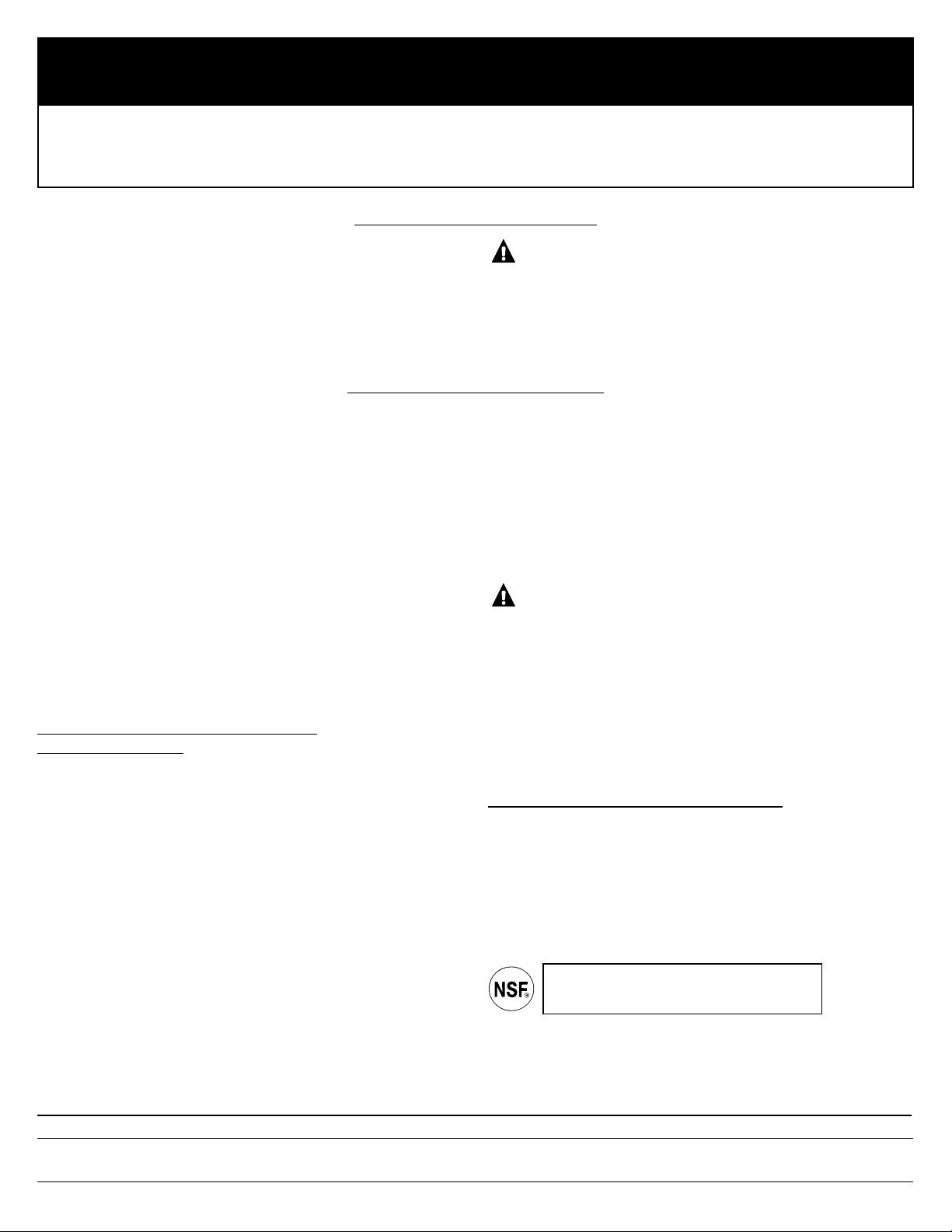
CONTENTS INCLUDED WITH PRODUCT
■ Filter housing and head
■ Product literature
■ Canister wrench
■ Timer and batteries
■ Mounting bracket
■ 4 Hex-head screws and 4 Hex washer-head screws
1
GE
INSTALLATION INSTRUCTIONS
Heavy-Duty Water Filtration Unit—GXWH40L (filters not included)
SAFETY PRECAUTIONS
■ Check with your state and local public works department for
plumbing and sanitation codes. You must follow these guidelines
as you install the Heavy-Duty Water Filtration Housing. Using a
qualified installer is recommended.
■ Be sure the water supply conforms with the
Performance Data
.
If the water supply conditions are unknown, contact your
municipal water company.
WARNING:
Do not use with water that is
microbiologically unsafe or of unknown quality without adequate
disinfection before or after the system.
■ It is highly recommended that a water shut-off valve be placed
directly upstream of your household filter.
■
Check with your local public works department for plumbing codes.
You must follow their guides as you install the Heavy-Duty Water
Filtration Housing.
■
Use the Heavy-Duty Water Filtration Housing on a potable, safe-todrink, home COLD water supply only. The filter cartridge will not
purify water or make unsafe water safe to drink. DO NOT use on
HOT water (100°F max).
■
Protect the Heavy-Duty Water Filtration Housing and piping from
freezing. Water freezing in the housing will damage it.
■
Your Heavy-Duty Water Filtration Housing will withstand up to 100
psi water pressure. If your house water supply pressure is higher
than 100 psi during the day (it may reach higher levels at night),
install a pressure-reducing valve before the housing is installed.
■ Do not install on
HOT WATER
. The temperature of the water
supply to the Heavy-Duty Water Filtration Housing must be
between the minimum of 40°F and the maximum of 100°F.
See the
Performance Data
section.
■
Do not
install the Heavy-Duty Water Filtration Housing using
copper solder fittings. The heat from the soldering process
will damage the unit.
WARNING:
Discard all unused parts and packaging
material after installation. Small parts remaining after installation
could be a choke hazard.
■
Do not
install filter in an outside location or anywhere it will be
exposed to sunlight.
PROPER INSTALLATION
This Heavy-Duty Water Filtration Housing must be properly installed and located in accordance with the Installation
Instructions before it is used.
GXWH40L is
Tested and Certified by NSF International
against NSF/ANSI
Standard 42 with cartridge FXHTC
for the reduction of Chlorine, Taste and Odor.
184D1061P003 (04-09 JR) 49-50220-3
GEAppliances.com
GENERAL ELECTRIC COMPANY, Appliance Park, Louisville, KY 40225
Page 2
Control Handle
OFF
■ Shuts off water.
FILTER
■ For filtered water. Directs water flow
through filter.
BYPASS
■ Permits flow of water to the house without flowing through the filter.
Use this position for filter changes or if filtered water is not desired
.
2
Filter Cartridge Replacement
You should change your filter when the water flow is noticeably reduced or at least every 3 months.
Turn off water to filter. Rotate the control handle to the
BYPASS or OFF position (see
Valve Operations
section).
Press the red pressure-release button to release pressure.
Unscrew the filter canister and discard used filter. Wash the
filter canister with mild soap and water.
Do not
use harsh
cleaners or hot water.
Inspect the filter canister O-ring. Make sure it is lightly
lubricated with clean food-grade silicone grease (silicone
grease is available through GE Parts and Service:
1.800.626.2002, part number WS60S10005). Be sure the
O-ring is seated in the groove. It is recommended that you
replace the O-ring if it is damaged.
Place a new filter cartridge into the canister, making sure it
is centered and completely seated on the bottom seal.
Reinstall the filter canister to the unit. Use the canister
wrench to tighten the canister. DO NOT OVERTIGHTEN.
Slowly rotate the control handle to the FILTER position.
Press the red pressure-release button to remove trapped air.
After installation, open any downstream faucet and flush the
cartridge for 15 minutes, wait one hour, then flush again for
15 minutes before using the water.
9
8
7
6
5
4
3
2
1
Installation Overview
NOTE: Be sure to allow a minimum space
of 11⁄
2
″–2″
under the filter for removing
the sump to change the cartridge.
Turn canister wrench
clockwise to remove
Canister
Turn
clockwise
to remove
canister
Turn
counterclockwise
to tighten
Red pressurerelease button
Filter
cartridge
O-ring seal
Filter canister
Head
STEP-BY-STEP INSTALLATION INSTRUCTIONS
Recommended
shut-off valve
Recommended
shut-off valve
Fitting
Ferrule
Hex nut
Fitting
Ferrule
Hex nut
11⁄2 ″–2″
Typical installation
Remote timer
Mounting
bracket
CARTRIDGE SPECIFICATIONS
Influent Challenge Reduction Average
Substance Concentration Requirements Reduction
Standard 42
Chlorine 2.0 mg/L ± 10% ≥ 50% 87.8%
Performance Data
This system has been tested according to NSF/ANSI 42
for the reduction of the substances listed at right. The
concentration of the indicated substances in water
entering the system was reduced to a concentration
less than or equal to the permissible limit for water
leaving the system, as specified in NSF/ANSI 42.
FXHTC Cartridge
Test Conditions
Flow Rate: 3 gpm (11.4 Lpm)
pH: 7.5± 1
Inlet Pressure: 60 PSI (4.1 bar)
Temperature: 68°F ± 5°F (19.8°C ± 2.5°C)
Operating Requirements
Pressure: 30–100 PSI (2.1–6.9 bar)
Turbidity: 5 NTU Max.
Temperature: 40°F–100°F (4.4°C–37.7°C)
Capacity: 30,000 gallons (113,562L) or 3 months
Testing was performed under standard laboratory conditions; actual performance may vary.
Control handle
Page 3
3
STEP-BY-STEP INSTALLATION INSTRUCTIONS (cont.)
Select Location
Select a location for the filter that is:
■ protected from freezing.
■ not exposed to direct sunlight.
It is recommended that a shut-off valve be placed on both sides of the filter.
It is recommended that a mounting bracket be used.
Install Mounting Bracket and Fittings
Instructions are for installing fittings onto copper plumbing. If the unit is
to be installed on any other type of tubing (plastic, PVC, galvanized),
consult a qualified plumber for additional hardware.
Attach heavy-duty mounting bracket to head assembly
with four hex-head screws as shown in illustration.
The bracket can be used as a template for marking the
location of the mounting screws.
Apply 4 or 5 wraps of Teflon tape, in a clockwise direction,
to the pipe threads of each fitting.
DO NOT
use joint
compound on any parts connecting to filter housing.
Assemble fitting to the inlet and outlet of the head.
Start each fitting by hand to make sure they
don’t cross-thread. Use an adjustable wrench
to tighten fittings.
DO NOT OVERTIGHTEN.
About 1–2 thread(s) should remain visible.
Use four hex washer-head screws to mount bracket to the wall firmly.
Use proper anchors on wall. Anchors are
NOT
included.
Install the head cover.
Head cover is reversible
for various installations.
Install the handle.
6
5
4
1
3
2
Cut Water Line
WARNING:
A copper or galvanized cold water pipe may
be used to ground electrical outlets in the home. Failure to maintain this
ground path may result in an electric shock hazard. If the cold water
pipe is used to ground electrical outlets, please refer to the
Installing the
Ground Wire
section before cutting the pipe.
Turn off the water supply and open a nearby faucet to drain the
water out of pipes.
Using a tape measure or ruler, measure the distance “D” as shown.
■
NOTE:
It is recommended that the shut-off valve be placed before and
after the filter as shown in the
Installation Overview
illustration.
■ Select a secure location surface to install filter and mounting bracket.
The location should align the filter housing with inlet and outlet pipe
and should not cause the pipes to bend or damage. Mark the distance
“D” on the pipe. D is about 7
3
⁄4″.
Using a pipe cutter, cut pipe. Sand (file) cut ends of pipe to ensure
that they are square and smooth.
■
NOTE:
Have a bucket and towel available to collect excess water.
2
1
3
Installing the Unit
Align filter assembly with pipe ends making certain that the
incoming
water supply is going into the filter opening marked “IN”. It may be
necessary to spread the pipe ends apart to install filter assembly.
Using two adjustable wrenches, hold incoming fitting securely with
one wrench and tighten nut with second wrench. Repeat this
procedure for outgoing fitting.
If mounting bracket is not used, support the water pipe on either
side of the filter unit.
Install a filter and tighten canister to seal (see
Filter Cartridge
Replacement
section).
4
3
2
1
Final Check
Install filter, if not already done (see
Filter Cartridge Replacement
section).
Slowly turn on water supply.
Check entire system for leaks.
If leaking from fittings, shut off water pressure and tighten or reseal
fittings. If leaking from the canister, tighten canister with a wrench.
After installation, flush the cartridge for 15 minutes, wait one hour,
then flush again for 15 minutes before using the water.
1
5
4
3
2
Teflon
tape
D
Attach Fittings to Water Line
Slip a compression nut onto each pipe.
Next, slip the brass ferrule onto each pipe.
2
1
Hex Nut
Brass ferrule
Hex Nut
Brass ferrule
D
Installing the Ground Wire
NOTE:
If your house plumbing is plastic, it would not be used as a
grounding path, and this step should be skipped.
IMPORTANT:
A copper or galvanized house cold water pipe is often used
to ground electrical outlets in the home.
Grounding protects you from
electrical shock.
The water filter housing may have broken this ground
path. To restore connection, install an 18″-long, 6-gauge copper wire
across the filter, tightly clamped using UL-approved 1/2″–1″ bronze
grounding clamps at both ends as shown. Zinc clamps should not be
used on copper plumbing. Wire and clamps may be purchased separately
from your local hardware store.
Clean copper pipe and ends of wire with emery paper. Bare wire is
recommended. If insulated wire is used, it should be stripped 3/4″
at each end before cleaning with emery paper.
Attach bronze clamps to pipe. Tighten screws.
Attach wire to clamps as shown. Tighten screws.
3
2
1
Clamp
Ground wire
Head cover
Bracket
Handle
Page 4
4
Ref. No. Part No. Part Description
003 WHTIMER Timer 1
004
HDCOVER–PLUG
Protective Cover with Cover Plug 1
005 HDHANDLE Bypass Handle 1
006 HDRING O-Ring 1
007 HDWRNCH Canister Wrench 1
008 FXHTC Filter Element—Carbon Filter —
FXHSC Filter Element—Pleated —
009 HDBRKT–2 Mounting Bracket 1
999 49-50220-3 Installation Instructions 1
To obtain replacement parts, call toll-free 800.626.2002 (U.S.),
800.663.6060 (Canada–English), 800.361.3869 (Canada–French).
999
008
006
007
Timer Installation and Reset Instructions
Timer cap
Timer base
Timer seat
Head
2 AAA
batteries
Timer battery installation and change
Insert coin or screwdriver in the slot between timer
cap and base. Gently pry them open and separate time
base from cap. Install or change 2 new AAA 1.5-volt
batteries. After having the batteries in place, line up
the base and cap and snap them back together.
It is recommended to change the batteries at least
every 2 filter changes.
Do not mix old and new batteries. Do not mix
alkaline, standard (carbon-zinc) or rechargeable
(ni-cad, ni-mh, etc.) batteries.
Installation of timer
Hold the timer body in the center and gently push
timer to its seat at the top of the head. Or attach it in
a remote location for easy viewing.
Timer reset and application
After new batteries are installed or filter is changed,
push and hold the timer blue reset button for
approximately 5 seconds. Release the reset button after
the light flashes 5 times. The light will flash again in
90 days to remind you that it is time to change the filter.
Blue reset button
009
003
LIMITED ONE-YEAR WARRANTY
• What does this warranty cover?
— Any defect in materials or workmanship in the manufactured product.
• What does this warranty not cover?
— Filter cartridge and batteries after 30 days from date of purchase.
— Service trips to your home to teach you how to use the product.
— Improper installation, delivery or maintenance.
— Failure of the product if it is abused, misused, altered, used
commercially or used for other than the intended purpose.
— Use of this product where water is microbiologically unsafe or
of unknown quality, without adequate disinfection before or after
the system. Systems certified for cyst reduction may be used on disinfected
water that may contain filterable cysts.
— Damage to the product caused by accident, fire, floods or acts of God.
— Incidental or consequential damage caused by possible defects with
this appliance, its installation or repair.
• For how long after the original purchase?
— One (1) year.
• How do I make a warranty claim?
— Return to the retailer from which it was purchased, along with a copy
of the “Proof of Purchase.” A new or reconditioned unit will be provided.
This warranty excludes the cost of shipping the product to your home.
This warranty is extended to the original purchaser and any succeeding owner
for products purchased for home or office use within the USA. In Alaska, the
warranty excludes the cost of shipping or service to your home or office.
Some states do not allow the exclusion or limitation of incidental or
consequential damages. This warranty gives you specific legal rights, and you
may also have other rights, which vary from state to state. To know what your
legal rights are, consult your local or state consumer affairs office or your state’s
Attorney General.
Contact us at GEAppliances.com, or call toll-free at 800.952.5039 in the U.S.,
or 866.777.7627 in Canada.
EXCLUSION OF IMPLIED WARRANTIES—Your sole and
exclusive remedy is product exchange as provided in this
Limited Warranty. Any implied warranties, including the implied
warranties of merchantability or fitness for a particular purpose,
are limited to one year or the shortest period allowed by law.
PARTS LIST
004
005
Page 5

■
Consulter le service local des travaux publics au sujet des codes de
plomberie. L’installation du logement de filtration d’eau pour service
rigoureux doit être conforme aux prescriptions du code de plomberie local.
■
Utiliser le logement de filtration d’eau pour service rigoureux uniquement
sur une canalisation d’eau potable FROIDE. Les cartouches de filtration
ne purifient pas l’eau et ne peuvent rendre potable une eau qui ne l’est
pas. NE PAS utiliser ce produit sur une canalisation d’eau CHAUDE
(100°F maximum).
■
Protéger le logement de filtration d’eau pour service rigoureux et la
tuyauterie contre le gel. La congélation d’eau dans le logement lui fera
subir des dommages.
■
Le logement de filtration d’eau pour service rigoureux peut résister à une
pression maximale de 100 lb/po
2
. Si la pression de distribution locale est
supérieure à 100 lb/po
2
durant la journée (elle peut atteindre un niveau plus
élevé la nuit), installer un robinet de réduction de pression en amont du
logement de filtration d’eau.
■ Ne pas installer le logement sur une canalisation
D’EAU CHAUDE
.
La température de l’eau à filtrer pour service rigoureux doit être
située entre 40°F (minimum) et 100°F (maximum). Voir les
Caractéristiques complètes
.
■ Lors de l’installation du logement de filtration d’eau pour service
rigoureux,
ne pas
utiliser des raccords de cuivre à souder. La chaleur
émise lors de l’opération de soudage fera subir des dommages
au système.
AVERTISSEMENT :
Éliminer en sécurité les
petites pièces qui peuvent rester inutilisées après l’installation; elles
peuvent susciter un danger d’étouffement pour les jeunes enfants.
■
Ne pas
installer le filtre à l’extérieur ou à un endroit exposé au
rayonnement solaire.
OUTILLAGE ET ACCESSOIRES REQUIS
POUR L’INSTALLATION
■ 2 Clés à molette
■ Coupe-tuyau
■ Mètre ruban ou mètre règle
■ Perceuse sans fil
■ Lime
■ Papier Émeri
■ Tournevis
■ Il peut être nécessaire d’avoir des accessoires complémentaires :
• 2 raccords pour relier le tuyau de l’habitation au filetage du NPTF
• Attaches de mise à la masse homologuées UL et fil de mise à la masse
en cuivre de calibre 6
• Ruban en Téflon
Les accessoires en option sont disponibles (cartes Visa, Mastercard ou Discover
acceptées) en visitant notre site Web à www.electromenagersge.ca ou en vous
adressant à notre service des Pièces et Accessoires au 800.626.2002 (U.S.) ou
800.361.3869 (Canada).
ARTICLES FOURNIS AVEC LE PRODUIT
■ Corps de filtre et tête de filtre
■ Brochures descriptives
■ Clé pour absorbeur
■ La minuterie et les piles
■ Support de montage
■ 4 vis à tête hexagonale et 4 vis avec tête à rondelle hexagonale
5
184D1061P003 (04-09 JR) 49-50220-3
www.electromenagersge.ca
GENERAL ELECTRIC COMPANY, Appliance Park, Louisville, KY 40225
MESURES DE SÉCURITÉ
■ Consulter le service local des travaux publics au sujet des codes de
plomberie et de raccordement aux égouts. L’installation du logement
de filtration d’eau pour service rigoureux doit être conforme aux
prescriptions du code de plomberie local. On recommande qu’un
installateur qualifié soit chargé de l’installation.
■ Vérifier que l’eau à traiter est conforme aux
Caractéristiques complètes
.
Si les caractéristiques de l’eau à traiter ne sont pas connues, contacter
le service municipal de distribution d’eau.
AVERTISSEMENT :
Ne pas utiliser ce produit
avec de l’eau microbiologiquement polluée ou de qualité inconnue sans
avoir installé un dispositif de désinfection approprié avant ou après
le système.
■ On recommande fortement l’installation d’un robinet d’arrêt
directement en amont du système de filtration.
INSTRUCTIONS D’INSTALLATION
Avant toute utilisation, on doit installer le logement de filtration d’eau (pour service rigoureux) à un emplacement adéquat conformément
aux instructions d’installation.
GE
INSTRUCTIONS D’INSTALLATION
Unité de filtration d’eau pour service rigoureux—GXWH40L (filtres non inclus)
Le système GXWH40L a été testé et homologué par
NSF International selon la norme NSF/ANSI 42 avec une
cartouche FXHTC en matière de réduction de chlore, du
goût et de l’odeur.
Page 6

6
Remplacement de la cartouche de filtration
On doit changer la cartouche de filtration lorsque le débit d’eau diminue sensiblement, et au moins à intervalles de trois mois.
Fermer l’arrivée d’eau au filtre, faites tourner la poignée de contrôle
jusqu’à la position BYPASS (dérivation) ou OFF (arrêt) (consulter la
section au sujet du fonctionnement du robinet).
Dépressuriser : appuyer sur le bouton rouge.
Dévisser le corps de filtre; jeter la vieille cartouche. Laver le corps de
filtre avec de l’eau et un savon doux.
Ne pas
utiliser de l’eau chaude
ou un produit de nettoyage énergique.
Inspecter le joint torique du corps de filtre. Assurez-vous que le joint
torique soit légèrement lubrifié avec de la graisse de silicone
alimentaire (vous trouverez la graisse de silicone au service de pièces
et d’entretien GE, en téléphonant au 1.800.626.2002, numéro de
pièce WS60S10005). Assurez-vous que le joint torique repose bien
dans le sillon. Remplacer le joint torique s’il est endommagé.
Placer la nouvelle cartouche de filtration dans le corps de filtre; placer
correctement et bien centrer la cartouche sur le joint du fond.
Revisser le corps de filtre sur la tête. Utilisez le clé pour absorbeur
fournie pour serrer la cartouche de filtration. NE PAS SERRER
EXCESSIVEMENT.
Faites tourner lentement la poignée de commande jusqu’à la
position FILTER (filtre).
Appuyer sur le bouton rouge pour permettre l’évacuation de l’air piégé.
Après l’installation,
ouvrir l’un des robinets en aval et
rincer la
cartouche pendant 15 minutes; attendre une heure, puis rincer de
nouveau pendant 15 minutes avant de puiser de l’eau.
9
8
7
6
5
4
3
2
1
Illustration de l’installation
NOTE : Veiller à ce qu’il y ait un espace libre d’au moins
1
1
⁄2 –2 po sous le filtre pour l’extraction du corps de filtre
lors du changement de la cartouche.
Tournez la clé à
cartouche dans le
sens des aiguilles
d’une montre pour
enlever
Absorbeur
Dévissage–
rotation dans
le sens horaire
Vissage–
rotation dans le
sens antihoraire
Bouton rouge de
dépressurisation
Cartouche
de filtration
Joint torique
Corps de filtre
Tête
ÉTAPES DE L’INSTALLATION
Robinet d’arrêt–
recommandé
Robinet d’arrêt–
recommandé
Raccord
Bague d’extrémité
Écrou hex
Raccord
Bague d’extrémité
Écrou hex
11⁄2 –2 po
Minuterie à
distance
Brides de
montage
SPÉCIFICATIONS DE CARTOUCHE
Concentration
d’agents polluants Spécifications Réduction
Substance dans l’arrivée d’eau de réduction moyenne
Norme 42
Chlore 2,0 mg/l± 10% ≥ 50% 87,8%
Caractéristiques complètes
Ce système a été testé selon NSF/ANSI 42 pour la réduction
des substances répertoriées à droit. La concentration des
substances indiquées dans l’arrivée d’eau du système a été
réduite à une concentration inférieure ou égale à la limite
admissible pour l’eau sortant de le système, comme
spécifié par NSF/ANSI 42.
Cartouche FXHTC
Conditions de test
Débit : 11,4 l/min (3 gal/min)
pH : 7,5± 1
Pression d’entrée : 60 psi (4,1 bar)
Température : 19,8 ± 2,5 °C (68 ± 5 °F)
Spécifications de fonctionnement
Pression : 30 à 100 psi (2,1 à 6,9 bar)
Turbidité : 5 NTU max
Température : 4,4 à 37,7 °C (40 à 100 °F)
Capacité : 113,562 l (30,000 gal) ou 3 mois
Les tests sont effectués dans des conditions standard de laboratoire; la performance réelle de
l’équipement peut varier.
Poignée
de contrôle
Poignée de contrôle
OFF (arrêt)
■ Coupe l’eau.
FILTER (filtre
)
■ Pour obtenir de l’eau filtrée. Fait
passer l’eau par le filtre.
BYPASS (dérivation)
■
Permet la circulation d’eau à la maison sans la faire passer par le filtre. Utilisez
cette position pour changer le filtre ou si vous n’avez pas besoin d’eau filtrée.
Page 7

Pose des raccords
Les instructions sont destinées à l’installation des raccords sur la tuyauterie
en cuivre. Si l’unité doit être installée sur tout autre type de tuyau (plastique,
PVC, galvanisé), consultez un plombier qualifié pour de la quincaillerie
supplémentaire.
Fixez le support de montage sec à l’ensemble de tête avec
quatre vis à tête hexagonale comme le montre l’illustration.
Vous pouvez utiliser le support de montage comme gabarit
pour marquer l’emplacement des vis de montage.
Enrouler 4 ou 5 tours de ruban de Teflon (sens horaire) sur le
filetage pour chaque raccord.
NE PAS
utiliser un composé
d’étanchéité sur les pièces connectées au corps de filtre.
Installer un raccord sur la tête du filtre, à l’entrée et à la sortie.
Commencer le vissage à la main et veiller à ne pas détériorer le
filetage. Utiliser une clé à molette pour serrer les
raccords.
NE PAS SERRER EXCESSIVEMENT
. Un filet
ou deux doivent rester visibles.
Utilisez quatre vis à rondelle hexagonale pour bien fixer le
support au mur. Utilisez les bonnes ancres pour le mur. Les
ancres ne sont
PAS
comprises.
Installez le couvercle de tête.
Le
capuchon est réversible pour
diverses installations.
Installez la poignée.
6
5
4
1
3
2
7
ÉTAPES DE L’INSTALLATION (suite)
Emplacement d’installation
Choisir l’emplacement approprié comme suit :
■ pas d’exposition au gel.
■ pas d’exposition au rayonnement solaire direct.
On recommande d’installer un robinet d’arrêt de chaque côté du filtre.
Il est recommandé d'utiliser un support de fixation.
Sectionnement de la canalisation d’eau
AVERTISSEMENT :
Une canalisation d’eau froide
en cuivre ou en acier galvanisé peut être utilisée pour la mise à la terre des
prises d’alimentation électrique dans la maison. Le défaut de maintenir
ce trajet de mise à la terre peut entraîner un risque d’électrocution. Si la
canalisation d’eau froide est utilisée pour la mise à la terre des prises
d’alimentation électrique, veuillez consulter la section
Installation du
conducteur de liaison à la terre
avant de couper la canalisation.
Fermer l’arrivée d’eau; ouvrir un robinet pour purger l’eau des tuyauteries.
À l’aide d’un ruban-mètre ou d’une règle, mesurer la distance «D» indiquée
sur l’illustration.
■
NOTE :
On recommande d’installer un robinet d’arrêt avant et après le filtre—
voir
l’illustration de l’installation
.
■ Choisissez une surface solide pour installer le filtre et le support de montage.
L’emplacement doit aussi être choisi de façon à aligner le filtre sur les
canalisations d’entrée et de sortie et à ne pas plier ou endommager celles-ci.
Marquer la distance «D» sur la tuyauterie. D est aux environs de 7
3
⁄4 po.
Avec un coupe-tuyau, couper la canalisation. Poncer à chaque extrémité
pour éliminer les bavures.
■
NOTE :
Préparez un seau et une serviette pour récolter l’eau qui coule.
2
1
3
Installation du conducteur de liaison à la terre
NOTE :
Si les tuyauteries de votre domicile sont en plastique, elles ne peuvent être
utilisées pour une liaison à la terre, dans ce cas, ignorez cette étape.
IMPORTANT :
Fréquemment, on utilise un tuyau d’eau froide en cuivre ou en
métal galvanisé pour effectuer une liaison à la terre des prises électriques de la
maison.
Cette mise à la masse vous protège contre les chocs électriques
et cette
liaison à la terre peut voir été neutralisée par le logement du filtre d’eau. Pour
rétablir la connexion, montez un fil en cuivre de 18 po et de calibre 6 le long du
filtre, lequel sera fixé solidement au moyen d’attaches en bronze homologuées
par UL de dimensions variant entre 1/2 po – 1 po à chaque extrémité comme
indiqué. N’utilisez pas d’attaches en zinc sur le cuivre. Il est possible d’acquérir le
fil et les attaches séparément chez votre quincaillier.
Nettoyez le fil en cuivre et ses extrémités avec du papier Émeri. Il est
recommandé de dénuder le fil. Si le fil est isolé, il faut le dénuder sur une
longueur de 3/4 po à chaque extrémité avant de les passer au papier Émeri.
Placez les attaches en bronze sur le fil. Serrez les vis.
Fixez le fil sur les attaches comme indiqué. Serrez les vis.
3
2
1
Contrôle final
Installez le filtre, si vous ne l’avez pas encore faites (voir la partie de
Remplacement de la cartouche de filtration
).
Ouvrir doucement l’arrivée d’eau.
Inspecter l’ensemble du système pour rechercher les fuites.
S’il y a une fuite des joints, fermer l’arrivée d’eau et resserrer les raccords ou
améliorer leur étanchéité. Si la cartouche fuit, serrez-la avec une clé.
Après l’installation, rincer la cartouche pendant 15 minutes; attendre une
heure, puis rincer de nouveau pendant 15 minutes avant de puiser de l’eau.
1
5
4
3
2
Ruban de
Teflon
D
Bride
Conducteur de liaison
à la terre
Installation des raccords sur la canalisation
Sur chaque tuyau, enfiler l’écrou de compression.
Enfiler ensuite la bague d’extremite sur chaque tuyau.
2
1
Écrou hexagonal
Bague d’extremite
Écrou hexagonal
Bague d’extremite
D
Installation du filtre
Aligner le filtre avec les deux sections de la canalisation; veiller à ce que la
canalisation
d’arrivée
soit placée devant l’entrée du filtre, marquée «IN». Il
peut être nécessaire d’écarter les deux sections de la tuyauterie pour installer
le filtre.
Au moyen de deux clés à molette, maintenir le raccord d’arrivée solidement
avec une clé et serrer l’écrou avec la seconde clé. Répéter le processus pour
le raccord de sortie.
Si le support de montage n’est pas utilisé, soutenir la tuyauterie d’eau de
chaque côté du filtre.
Installez un filtre et serrez la cartouche pour sceller (consultez la section de
Remplacement de la cartouche de filtration
).
4
3
2
1
Couvercle
de tête
Brides
Poignée
Page 8

8
Installation de la minuterie et instructions de réglage
Capuchon de
la minuterie
Base de la minuterie
Joint de
la minuterie
Tête
2 piles AAA
Installation et remplacement de la pile de la minuterie
Insérez une pièce ou un tournevis entre le capuchon de
minuterie et sa base. Ouvrez doucement en faisant levier et
séparez la base de la minuterie de son capuchon. Installez
ou remplacez les deux piles AAA 1,5 volt. Après avoir mis
les piles en place, alignez la base et le capuchon et fixez-les
ensemble.
Nous vous recommandons de remplacer les piles à moins
tous les deux changements de filtre.
Ne mélangez pas des piles usées avec des neuves,
ni des piles alcalines avec des piles standard (carbone-zinc)
ou rechargeables (ni-cad, ni-mh, etc.).
Installation de la minuterie
Tenez la minuterie de au centre et poussez doucement
la minuterie jusqu’à ce qu’elle soit fixée en haut de la tête.
Ou fixez-la dans un emplacement éloigné où vous pourrez
la lire facilement.
Réglage de la minuterie et application
Après avoir installé de nouvelles piles et changé les filtres,
appuyez sur le bouton bleu de remise à zéro de la minuterie
et maintenez-le appuyé pendant environ 5 secondes.
Relâchez le bouton de réglage après que la lumière ait
brillé cinq fois. La lumière se remettra en marche dans
90 jours pour vous rappeler de changer votre filtre.
Bouton bleu de remise à zéro
GARANTIE LIMITÉE D’UN AN
• Que couvre la garantie?
— Tout défaut de matériel ou de main d’oeuvre du produit.
• Q’est-ce qui n’est pas couvert par la garantie?
— La cartouche de filtre et les piles après trente jours à partir de la date d’achat.
—
Les déplacements à votre domicile pour vous enseigner comment utiliser le produit.
— Une installation, remise ou entretien incorrecte.
— Une panne du produit causée par un abus d’utilisation, une mauvaise utilisation,
toute modification, exploitation commerciale ou une utilisation du produit dans
un but non prévu.
—
Utilisation de ce produit lorsque l’eau est microbiologiquement impure ou de qualité
inconnue sans qu’une désinfection adéquate n’ait eu lieu avant l’entrée et sortie dans
le circuit. Les systèmes homologués pour une réduction des microbes peuvent être
utilisés après désinfection de l’eau pouvant contenir des microbes filtrables.
— Tout dommage causé au produit par accident, incendie, inondation ou acte
de Dieu.
— Tout dommage fortuit ou indirect causé par des défauts éventuels de cet appareil,
son installation ou les réparations effectuées.
• Quelle est la durée de la garantie après l’achat?
— Un an.
• Comment dois-je faire ma réclamation?
—
Ramenez le produit au magasin où vous l’avez acheté avec une exemplaire de la
“Preuve d’achat”. Une unité neuve ou remise à neuf sera fournie. Cette garantie
exclut les coûts d’expédition ou les déplacements de service à votre domicile.
Cette garantie couvre l’acheteur original et tout propriétaire subséquent des produits
achetés à des fins résidentielles ou de bureau à l’intérieur des États-Unis. En Alaska, cette
garantie exclut le coût d’expédition ou les appels de service à votre maison ou bureau.
Certains États ne permettent pas l’exclusion ou la restriction des dommages accessoires
ou consécutifs. Cette garantie vous donne des droits juridiques particuliers, mais vous
pouvez également avoir d’autres droits qui varient d’État à État. Pour connaître vos droits
juridiques, consultez le bureau de protection du consommateur de votre localité, de
votre État ou le procureur général de votre État.
Contactez nous sur GEAppliances.com, ou appelez le numéro sans frais 800.952.5039
aux États-Unis. Au Canada, contactez nous sur www.electromenagersge.ca, ou appelez
le numéro sans frais 866.777.7627.
EXCLUSION DE GARANTIES IMPLICITES—Votre seul et unique
recours est l’échange du produit selon les dispositions de cette
Garantie limitée. Toutes les garanties implicites, incluant les
garanties de commercialité et d’adéquation à un usage
spécifique, sont limitées à une année ou à la période la plus
courte autorisée par la législation.
Node
repérage Pièce n
o
Description
003 WHTIMER Minuterie 1
004
HDCOVER–PLUG
Couvercle de protection
avec tampon de couvercle 1
005 HDHANDLE Poignée de dérivation 1
006 HDRING Joint torique 1
007 HDWRNCH Clé pour absorbeur 1
008 FXHTC Élément de filtre : au charbon —
FXHSC Élément de filtre – plaidé —
009 HDBRKT–2 Brides de montage 1
999 49-50220-3 Instructions d’installation 1
Pour obtenir des pièces de rechange, composez sans frais le 800.626.2002 (États-Unis),
le 800.663.6060 (Canada, langue anglaise), le 800.361.3869 (Canada, langue française).
999
008
007
009
LISTE DES PIÈCES
006
003
004
005
Page 9

HERRAMIENTAS QUE SE NECESITAN Y
ACCESORIOS PARA LA INSTALACION
■2 llaves ajustables
■
Cortador de tubos
■
Regla o cinta métrica
■
Taladro inalámbrico
■
Lima
■
Papel de esmeril
■
Destornillador
■
Es posible que se necesite partes adicionales para completar
la instalación:
• 2 accesorios para conectar la tubería de su residencia a las roscas
hembras NPTF de 1″ en el alojamiento del filtro
• Abrazaderas de toma de tierra aprobadas por UL y cable de
toma de tierra de cobre calibre 6
• Cinta de teflón
Los accesorios opcionales están disponibles (usando Visa, MasterCard o Discover)
visitando nuestro Website a GEAppliances.com o en el Departamento de Partes y
Accesorios en el 800.626.2002.
CONTENIDOS INCLUIDOS CON EL PRODUCTO
■
Caja y cabeza del filtro
■
Literatura del producto
■ Llave de rosca
■ Sincronizador y baterías
■ Abrazadera de montaje
■ 4 tornillos de cabeza hexagonal y cuatro tuercas de tornillos de cabeza
hexagonal
9
PRECAUCIONES DE SEGURIDAD
■ Consulte con su departamento de obras públicas local y estatal para
los códigos de plomería y sanidad. Usted debe seguir estas reglas a
medida que instale el alojamiento de filtración de agua extrafuerte.
El uso de un instalador calificado es recomendado.
■ Asegúrese que el abastecimiento de agua cumple con las
Datos
del desarrollo
. Si las condiciones del abastecimiento de agua son
desconocidas, póngase en contacto con su compañía de agua municipal.
ADVERTENCIA:
No use con agua que sea
bacteriológicamente insegura o de calidad desconocida sin una
desinfección adecuada antes o después del sistema.
■ Es altamente recomendado que la válvula de cierre sea colocada
directamente hacia arriba de su filtro de hogar.
INSTALACION CORRECTA
■
Consulte con su departamento de obras públicas local para los códigos de
plomería. Usted debe seguir sus guías a medida que instale el alojamiento
de filtración de agua extrafuerte.
■
Use el alojamiento de filtración de agua extrafuerte solamente en un
abastecimiento de agua potable FRIA de hogar, que sea buena para beber.
El cartucho del filtro no purificará el agua o hará que el agua que no sea
buena sea potable. NO USE en agua CALIENTE (100°F máx.).
■
Proteja el alojamiento de filtración de agua extrafuerte y las cañerías de la
congelación. El agua que se congele en el alojamiento lo dañará.
■
Su alojamiento de filtración de agua extrafuerte soportará hasta 100 psi de
presión de agua. Si la presión de agua de su casa es más de 100 psi durante
el día (podría alcanzar niveles más altos durante la noche), instale una
válvula para reducir la presión antes de que el alojamiento sea instalado.
■ No instale en
AGUA CALIENTE
. La temperatura de la línea de agua
hacia el alojamiento de filtración de agua extrafuerte debe estar entre
el mínimo de 40°F, y el máximo de 100°F. Vea las
Datos del desarrollo.
■
No
instale el alojamiento de filtración de agua extrafuerte usando
uniones de cobre soldadas. El calor del proceso de las soldaduras
dañará la unidad.
ADVERTENCIA:
Bote todas las partes y los materiales
de empaque sin usar después de la instalación. Las partes pequeñas
que sobren después de la instalación podrían ser un peligro para
atragantarse.
■
No
instale el filtro en una ubicación exterior o en un lugar donde
esté expuesto a la luz del sol.
Este alojamiento de filtración de agua extrafuerte debe ser instalado y ubicado correctamente de acuerdo con las instrucciones de
instalación antes de ser usado.
GE
INSTRUCCIONES DE INSTALACION
Unidad de filtración de agua extrafuerte—GXWH40L (filtros no incluidos)
184D1061P003 (04-09 JR) 49-50220-3
GEAppliances.com
GENERAL ELECTRIC COMPANY, Appliance Park, Louisville, KY 40225
GXWH40L es probado y certificado por la
NSF International contra el Estándar 42
NSF/ANSI con cartucho FXHTC para la
reducción de cloro, sabor y olor.
Page 10

Reemplazo del cartucho del filtro
Usted debería cambiar el filtro cuando el paso del agua disminuye notablemente o por lo menos cada tres meses.
Cierre el paso del agua al filtro. Gire la manija de control a la
posición BYPASS (derivación) o a la posición OFF (apagado)
(consulte la sección
Operación de la válvula
.
Empuje el botón rojo para reducir la presión para bajar la presión.
Desatornille el receptáculo y bote el filtro usado. Lave el receptáculo
del filtro con un jabón suave y agua.
No
use limpiadores fuertes o
agua caliente.
Inspeccione el anillo del receptáculo. Asegúrese que esté levemente
lubricado con grasa limpia de silicona de grado de alimentos (la
grasa de silicona está disponible a través del departamento de Partes
y Servicio de GE llamando al 1.800.626.2002, número de parte
WS60S10005). Cerciórese de que el aro tórico es asentado en la
ranura. Se recomienda que cambie el anillo si está dañado.
Coloque un filtro nuevo en el receptáculo asegurándose de que esté
centrado y completamente asentado sobre el fondo del sello.
Reinstale el receptáculo del filtro a la unidad. Use la llave de rosca
para apretar el receptáculo del filtro. NO APRIETE DEMASIADO.
Lentamente, gire la manija de control a la posición FILTER (filtro).
Empuje el botón rojo para reducir la presión para sacar el aire
atrapado.
Después de la instalación, abra cualquiera llave de agua después del
cartucho y lave el cartucho por 15 minutos, espere una hora, luego
lave nuevamente por 15 minutos antes de usar el agua.
9
8
7
6
5
4
3
2
1
Sumario de la instalación
NOTA: Asegúrese de dejar un espacio mínimo de
1
1
⁄2 ″–2″debajo del filtro para sacar el receptáculo,
para cambiar el cartucho.
Gire la llave del
receptáculo en
dirección de las
agujas del reloj
para remover
Depósito
Haga girar en
dirección del
reloj para sacar
el receptáculo
Haga girar
contra el reloj
para apretar
Botón rojo
para reducir
la presión
Cartucho
del filtro
Sello tipo anillo
Receptáculo
del filtro
Cabeza
INSTRUCCIONES DE INSTALACION PASO A PASO
Válvula de cierre
recomendada
Válvula de cierre
recomendada
Accesorio
Férula
Tuerca hexagonal
Accesorio
Férula
Tuerca hexagonal
11⁄2 ″–2″
10
Sincronizador
remoto
Abrazadera
de montaje
ESPECIFICACIONES DEL CARTUCHO
Concentración de Requisitos de Reducción
Substancia reto entrante reducción promedio
Estándar 42
Cloro 2,0 mg/L ± 10% ≥ 50% 87,8%
Datos del desarrollo
Este sistema ha sido probado de acuerdo con NSF/ANSI 42
para la reducción de las substancias mostradas a la derecha.
La contracción de las substancias indicadas en el agua que entra
en el sistema fue reducida a una concentración menor o igual
al límite permisible para el agua que sale del el sistema,
de acuerdo a las especificaciones de NSF/ANSI 42.
Cartucho FXHTC
Condiciones de prueba
Ritmo de flujo: 3 gpm (11,4 Lpm)
pH: 7,5± 1
Presión de entrada: 60 PSI (4.1 bar)
Temperatura: 68°F ± 5°F (19,8°C ± 2,5°C)
Requisitos de operación
Presión: 30–100 PSI (2,1–6,9 bar)
Turbidez: 5 NTU Max.
Temperatura: 40°F–100°F (4,4°C–37,7°C)
Capacidad: 30,000 galones (113,562 L)
o 3 meses
La prueba fue llevada a cabo bajo condiciones de laboratorio estándares, y el desarrollo real podría variar.
Manija
de control
Manija de control
OFF (apagado)
■ Cierra el agua.
FILTRO
■ Para agua filtrada. Dirige el flujo
del agua a través del filtro.
DERIVACIÓN
■ Permite el flujo del agua hacia la casa sin pasar por el filtro. Use esta
posición para los cambios de filtro o si no se desea agua filtrada.
Page 11

Instalación del cable de tierra
NOTA:
Si la tubería de su casa es de plástico no debería ser usada para efectuar la
conexión de tierra, y este paso puede ser obviado.
I
MPORTANTE:
Una tubería de agua fría galvanizada interiormente o de cobre es
usada muy a menudo para conectar a tierra los tomacorrientes eléctricos en las
casas.
Una toma de tierra lo protege de descargas eléctricas.
El alojamiento del filtro
de agua pudo haber interrumpido la trayectoria de tierra. Para restablecer la
conexión, instale un cable de cobre de 18″, de calibre 6 a través del filtro,
fuertemente sujeto utilizando abrazaderas de tierra de bronce de 1/2″ a 1″
aprobada por UL en ambos extremos de la línea como se muestra en la
ilustración. Usted no debe usar abrazaderas de cinc en tubería de cobre.
El cable y las abrazaderas pueden ser compradas por separado en su
ferretería local.
Limpie la tubería de cobre y los extremos del cable con papel de esmeril.
Se recomienda que utilice cable desnudo. Si utiliza cable aislado, las puntas
deberían estar desnudas de su protector, aproximadamente 3/4″ antes
de proceder a limpiarlas con papel de esmeril.
Sujete las abrazaderas de bronce a la tubería. Apriete los tornillos.
Sujete el cable a las abrazaderas tal como se muestra en la figura. Apriete
los tornillos.
3
2
1
INSTRUCCIONES DE INSTALACION PASO A PASO (cont.)
Seleccione la ubicación
Seleccione una ubicación para el filtro que esté:
■ protegida de la congelación.
■ que no esté expuesta a la luz directa del sol.
Se recomienda instalar una válvula de cierre en ambos lados del filtro.
Sugerimos que se utilice una ménsula de instalación.
Instalación de las uniones
I
nstrucciones para instalar accesorios en la tubería de cobre. Si la unidad va
a ser instalada sobre cualquier otro tipo de cañería (plástico, PVC, galvanizado),
consulte con un plomero calificado para las herramientas adicionales.
Pegue la abrazadera de alta resistencia a la ensambladura de
la cabeza con los cuatro tornillos de cabeza hexagonal que
se muestra en la ilustración.
La abrazadera se puede usar como una plantilla para marcar
la localización de los tornillos de montaje.
Aplique 4 o 5 vueltas de cinta de teflón, en la dirección del
reloj, a los hilos de la cañería de cada accesorio.
NO
use
compuestos para uniones en ninguna de las partes que
conecten la caja del filtro.
Arme un accesorio en la entrada y la salida de la cabeza.
Empiece cada unión con la mano para estar seguro que los
hilos no se crucen. Use una llave inglesa ajustable
para apretar los accesorios.
NO APRIETE DEMASIADO.
Uno o dos hilos deberían permanecer visibles.
Use los cuatro tornillos/tuercas de cabezas hexagonales para montar la
abrazadera a la pared firmemente. Use las anclas apropiadas en la pared.
Las anchas
NO
están incluidas.
Instale la tapa de cabeza. La
tapa de cabeza es reversible
para instalaciones varias.
Instale la manija.
6
5
4
1
3
2
Corte de la línea de agua
ADVERTENCIA:
Se pueden usar tubos para agua fría en
cobre o galvanizados para conectar a tierra las salidas eléctricas de la casa.
No mantener esta ruta de conexión a tierra puede resultar en un riesgo de
choque eléctrico. Si se usa la tubería de agua fría para conectar a tierra las
salidas eléctricas, consulte la sección
Cómo instalar el cableado de conexión a
tierra
, antes de cortar la tubería.
Cierre el paso del agua y abra una llave de agua cercana para sacar
el agua de las cañerías.
Usando una cinta para medir o una regla, mida la distancia “D” como
se muestra.
■
NOTA:
Se recomienda que la válvula de cierre sea colocada antes y después del
filtro como se muestra en la ilustración
Sumario de la Instalación
.
■ Seleccione una ubicación segura en la superficie para instalar el filtro y
el soporte de montaje. La ubicación debe alinear el alojamiento del filtro
con el tubo de entrada y el tubo de salida y no debe causar que los tubos
se doblen o se dañen. Marque la distancia “D” sobre el tubo. D es
aproximadamente 7
3
⁄4″.
Usando un cortador de cañerías, corte el tubo. Lije (lime) las puntas
cortadas para asegurarse que estén cuadradas y suaves.
■
NOTA:
Tenga una cubeta y una toalla disponible para colectar el agua
excesiva.
2
1
3
Revisión final
Instale el filtro, si todavía no se ha hecho (vea la sección para
Reemplazo
del cartucho del filtro
).
Lentamente abra el paso del agua.
Revise todo el sistema para que no hayan goteras.
Si hay goteras de las uniones a partir del accesorio, cierre la presión del agua
o reselle las uniones. Si existe una fuga a partir del receptáculo, apriételo
con una llave.
Después de la instalación, lave el cartucho por 15 minutos,
espere una hora, luego lave nuevamente por 15 minutos antes
de usar el agua.
1
5
4
3
2
Cinta de
teflón
D
Abrazadera
Alambre para hacer tierra
11
Conecte las uniones a la línea del agua
Deslice una tuerca de compresión en cada cañería.
Luego, deslice la férula de bronce en cada cañería.
2
1
Tuerca hexagonal
Férula de bronce
Tuerca hexagonal
Férula de bronce
D
Instalación de la unidad
Ponga en línea el juego del filtro con las puntas de la cañería asegurándose
que
la entrada
de la línea del agua vaya hacia la abertura marcada “IN”. Podría
ser necesario abrir las puntas de las cañerías para instalar el juego del filtro.
Usando dos llaves ajustables, sujete el accesorio de entrada firmemente con
una de las llaves y apriete la tuerca con la segunda llave. Repita el
procedimiento para el accesorio de salida.
Si no se utiliza el soporte de montaje, sujete la cañería de agua en cualquier
lado de la unidad del filtro.
Instale el filtro y apriete el receptáculo para sellar (ver la sección de
Reemplazo del cartucho del filtro
).
4
3
2
1
Tapa de cabeza
Abrazadera
Manija
Page 12

Instalacion del cronometro e instrucciones de reinicialización
Instalación y cambio de las baterías del cronómetro
Inserte una moneda o un destornillador en la ranura entre
la tapa y la base del sincronizador. Con gentileza haga palanca
entre ellos y separe la base de tiempo de la tapa. Instale o
cambie dos baterías AAA 1,5 voltios nuevas. Después de que
las baterías estén en su lugar, alinee la base y la tapa y únalas
nuevamente.
Se recomienda cambiar las baterías por lo menos 2 cambios
del filtro.
No mezcle baterías nuevas y viejas. No mezcle baterías
alcalinas, estándar (carbono-cinc) o recargables (ni-cad,
ni-mh, etc.).
Instalación del cronómetro
Sostenga el cuerpo del cronómetro en el centro y
suavemente empuje hacia su posición en la parte superior
de la cabeza. O péguela a una localización remota para verla
fácilmente.
Reinicialización y aplicación del cronómetro
Después de instalar las baterías nuevas o cambiar los filtros,
presione y sostenga el botón de reinicialización (reset) azul
del sincronizador por aproximadamente 5 segundos. Libere
el botón de reinicialización después de que la luz haya
parpadeado 5 veces. La luz volverá a parpadear en 90 días
para recordarle que debe cambiar el filtro.
12
Printed in China
Imprimé en Chine
Impreso en China
GARANTÍA LIMITADA POR UN AÑO
• ¿Qué cubre esta garantía?
— Cualquier defecto de fábrica en los materiales o la manufactura del producto.
• ¿Qué no cubre esta garantía?
— Cartucho del filtro y las baterías después de treinta días a partir de la fecha de la
compra.
— Viajes a su casa para enseñarle cómo usar el producto.
— Instalación o entrega inapropiada, o mantenimiento impropio.
— Fallas del producto si hay abuso, mal uso, o uso para otros propósitos que los
propuestos, o uso para fines comerciales.
—
Uso de este producto donde el agua está microbiológicamente insegura o de
calidad desconocida, sin la adecuada desinfección, antes y después de ser procesada
por el sistema. Los sistemas certificados para reducir el nivel de quistes pueden ser
usados en agua desinfectada que pueda contener quistes que se puedan filtrar.
— Daños causados al producto debido a accidentes, incendio, inundaciones o actos
de la naturaleza.
— Daños secundarios o por consecuencia causados por posibles defectos en el
producto, su instalación o reparación.
• ¿Por cuánto tiempo después de la compra?
— Un año.
• ¿Cómo hago la reclamación de la garantía?
— Devuélvala al minorista a quien le compró el producto con una copia
de “Proof of Purchase”(prueba de compra). Se le proporcionará una
unidad nueva o reacondicionada. Esta garantía excluye los costos de envío
o llamadas de servicio a domicilio.
Esta garantía se extiende al comprador original y cualquier comprador posterior de
productos comprados para uso residencial o en la oficina dentro de Estados Unidos. En
Alaska, la garantía excluye el costo de envío o las visitas de servicio a su casa u oficina.
Algunos estados no permiten la exclusión o las limitaciones de daños incidentales o
consecuenciales. Esta garantía da derechos legales específicos, y usted podría tener otros
derechos que variarán de estado a estado. Para saber cuáles son sus derechos legales, consulte
a la oficina de asuntos del consumidor local o la oficina del Attorney General en su localidad.
Póngase en contacto con nosotros en GEAppliances.com, o llame sin cargo al
800.952.5039, o 866.777.7627 en Canada.
EXCLUSIÓN DE GARANTÍAS IMPLÍCITAS—Su único y exclusivo derecho
es el cambio del producto, tal y como se indica en esta Garantía limitada.
Cualquier garantía implícita, incluyendo las garantías implícitas de
comerciabilidad o adecuación para un fin determinado, están limitadas
a un año o el período de tiempo más breve permitido por la ley.
No. de ref. Parte No. Descripción
003 WHTIMER Sincronizador 1
004
HDCOVER–PLUG
Tapa protector con tapón de tapa 1
005 HDHANDLE Manija de derivación 1
006 HDRING Anillo 1
007 HDWRNCH Llave de rosca 1
008 FXHTC Elemento del filtro: Filtro de carbón —
FXHSC Elemento del filtro – Plegado —
009 HDBRKT–2 Abrazadera de montaje 1
999 49-50220-3 Instrucciones de Instalación 1
Para obtener partes de repuesto, llame sin costo al 800.626.2002 (EE.UU.),
800.663.6060 (Canadá–inglés), 800.361.3869 (Canadá–francés).
999
008
007
009
LISTA DE PARTES
006
003
Tapa del cronómetro
Sello del cronómetro
Cabeza
2 baterías
AAA
Botón de reajuste azul
Base del cronómetro
004
005
 Loading...