

Page 1
REQUIRED TOOLS AND ACCESSORIES
FOR INSTALLATION
■
2 wrenches: 11⁄8″ and 11⁄4″
■
Pipe cutter or hacksaw
■
File
■
Emery paper
■
Screwdriver
■
For GXWH01C model, additional installation parts may
be required:
• (2)
3
⁄4″ compression adapters with brass ferrule and
nut for installation on copper plumbing –
Installation Kit available:
– Retail Part (WHKIT)
– GE Parts (WS35X10023)
• UL-approved grounding clamps and 8-gauge copper
grounding wire–Installation Kit available:
– Retail Part (WHKIT)
– GE Parts (WS35X10023)
• Teflon
®
Tape
• Sump Wrench
– Retail Part (UCWRNCH)
– GE Parts (WX5X140)
Optional accessories are available (Visa, MasterCard or Discover
cards accepted) by visiting our Website at www.GEAppliances.com
or from Parts and Accessories 800.626.2002 (U.S.) or
800.663.6060 (Canada).
■
If unit is to be installed on plastic, PVC, or galvanized
plumbing, separate hardware must be purchased.
CONTENTS INCLUDED WITH PRODUCT
■
Filter housing and head
■
Product literature
■
Sediment filter
(for GXWH08C)
■
(2) 3⁄4″
brass compression adapters with nut
and ferrule (for GXWH08C)
■
Teflon®tape (for GXWH08C)
■
Sump wrench (for GXWH08C)
■
Grounding clamps and wire (for GXWH08C)
1
GE SmartWater
™
INSTALLATION INSTRUCTIONS
Household Water Filtration System — GXWH01C and GXWH08C
251B6021P001 10-01 JR 49-50043-3
www.GEAppliances.com
GENERAL ELECTRIC COMPANY, Appliance Park, Louisville, KY 40225
SAFETY PRECAUTIONS
■
Check with your state and local public works
department for plumbing and sanitation codes.
You must follow these guidelines as you install
the Household Water Filtration System. Using
a qualified installer is recommended.
■
Be sure the water supply conforms with the Specifications
Guidelines. If the water supply conditions are unknown,
contact your municipal water company
.
WARNING:
Do not use with water that is
microbiologically unsafe or of unknown quality
without adequate disinfection before or after the system.
■
I
t is highly recommended that a water shut-off valve
be placed directly upstream of your household filter.
PROPER INSTALLATION
■ Check with your local public works department for
plumbing codes. You must follow their guides as you
install the Household Water Filtration System.
■ Use the Household Water Filtration System on a potable,
safe-to-drink, home COLD water supply only. The filter
cartridge will not purify water or make unsafe water safe
to drink. DO NOT use on HOT water (100˚F max).
■ Protect the Household Water Filtration System and piping
from freezing. Water freezing in the system will damage it.
■ Your Household Water Filtration System will withstand up to
125 psi water pressure. If your house water supply pressure
is higher than 100 psi during the day (it may reach higher
levels at night), install a pressure-reducing valve before the
system is installed.
■
Do not install on HOT WATER. The temperature of the
water supply to the Household Filtration System must
be between the minimum of 40
°F and the maximum
of 100°F
. See the Specification Guidelines
.
■ Do not install the Household Water Filtration System
using copper solder fittings. The heat from the soldering
process will damage the unit.
WARNING:
Discard all unused parts and packaging
material after installation. Small parts remaining after
installation could be a choke hazard.
■ Do not install filter in an outside location or anywhere
it will be exposed to sunlight.
This Household Water Filtration System must be properly installed and located in accordance with the Installation Instructions before it is used.
System is
Tested and Certified by NSF
International against ANSI/NSF
Standard
42 for nominal Particulate Reduction
Class III.
System is
Tested and Certified by NSF
International against ANSI/NSF
Standard
42 for nominal Particulate Reduction
Class III.
GXWH01C
GXWH08C
Page 2
2
ABOUT THE FILTER CARTRIDGE
Filter Cartridge Replacement
You should change your filter when the water flow is noticeably reduced or at least every three months.
Filter Cartridge Life
Several variables determine how long
the cartridge will last in your Household
Water Filtration System. These include:
■
levels of sediment or other undesirable
substances in your water.
■
the amount of water you use.
■
the filter location (filtering all or part of your
household water).
GE MODEL FUNCTION LIFE CONSTRUCTION
FXUSC* Sediment 3 month/16,000 gallons Polyspun
15 Micron
FXWPC Sediment 3 month/16,000 gallons Pleated
FXWSC Sediment 3 month/16,000 gallons String Wound
10 Micron
FXWTC* Sediment 3 month/15,000 gallons Carbon Paper
5 Micron
Chlorine
*NSF Certification for particulate reduction applies only to the FXUSC and FXWTC when
used in GXWH01C or GXWH08C Filtration Systems.
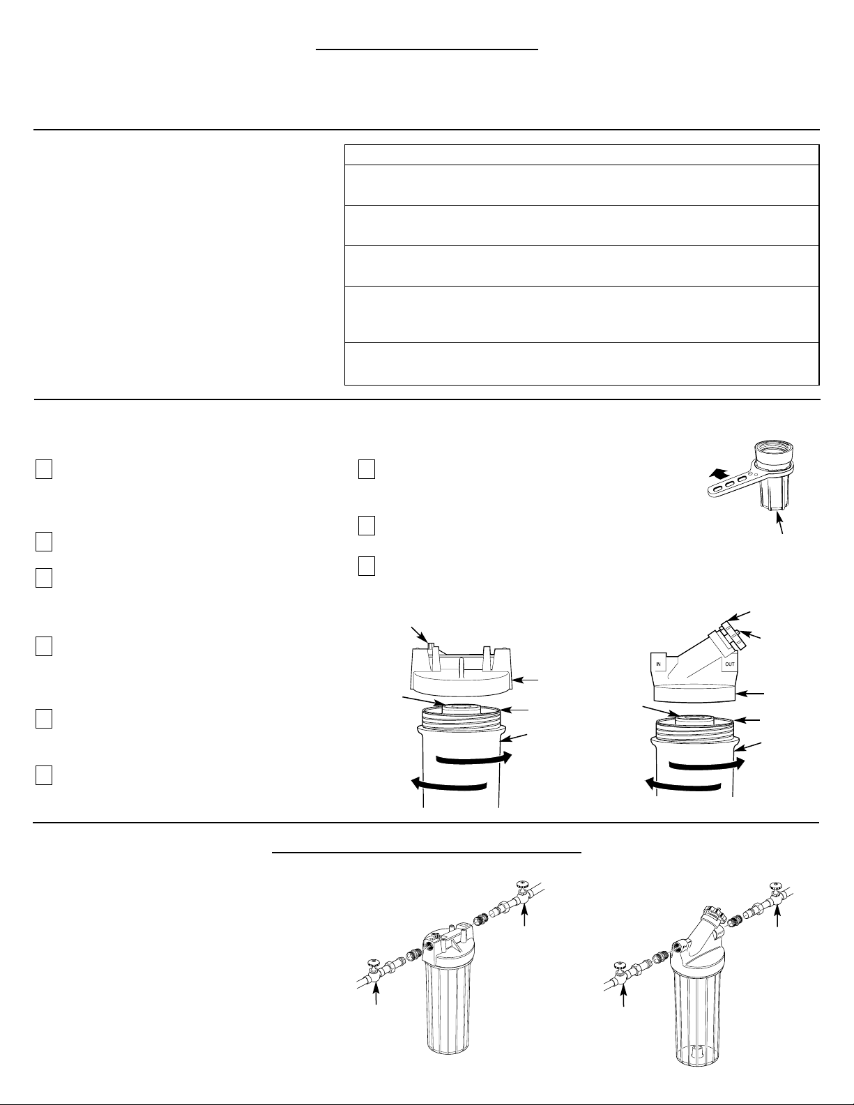
Turn off water to filter. For model GXWH01C,
water must be shut off from an upstream
valve. For model GXWH08C, rotate bypass
valve to the bypass position.
Press the red pressure release button to release
pressure.
Unscrew the filter canister and discard used
filter. Wash the filter canister with mild soap
and water. Do not use harsh cleaners or hot
water.
Inspect the filter canister O-ring. Make sure it
is lightly lubricated and completely seated in
the groove. It is recommended that you
replace the O-ring if it is damaged.
Place a new filter cartridge into the canister
making sure it is centered and completely
seated on the bottom seal.
Reinstall the filter canister to the unit. Hand
tightening is all that is required to seal the
unit.
Slowly turn on water to the filter by using the
bypass valve (model GXWH08C) or the
upstream shut-off valve.
Press the red pressure release button to
remove trapped air.
Open any downstream faucet and allow filter
system to flush for 5 minutes.
9
8
7
6
5
4
3
2
1
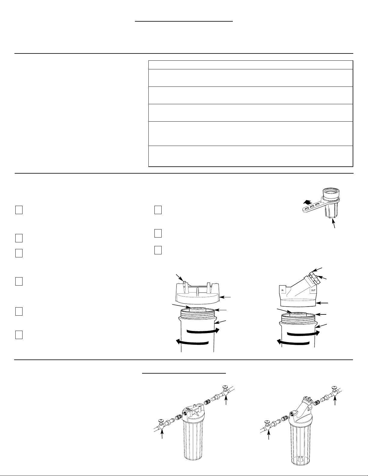
Installation Overview
NOTE: Be sure to allow a minimum space of 11⁄2 ″
under the filter for removing the sump, to change
the cartridge.
Turn sump wrench tool
clockwise to remove
(on some models)
Sump
Bypass valve
Filter
cartridge
O-ring seal
Red pressure
release button
Head
Filter canister
Turn
clockwise
to remove
canister
Tur n
counterclockwise
to tighten
Turn
clockwise
to remove
canister
Turn
counterclockwise
to tighten
Red pressure
release button
Filter
cartridge
O-ring seal
Filter canister
Head
GXWH01C
GXWH08C
Recommended
shut-off valve
Recommended
shut-off valve
GXWH01C
GXWH08C
Specification Guidelines
Minimum–Maximum Supply Water Pressure: 20–125 pounds per square inch (psi)
Minimum–Maximum Supply Water Temperature: 40°F/100°F Rated Service Flow: 4 gpm
Recommended
shut-off valve
Recommended
shut-off valve
STEP-BY-STEP INSTALLATION INSTRUCTIONS
Page 3
3
STEP-BY-STEP INSTALLATION INSTRUCTIONS (cont.)
Select Location
Select a location for the filter that is:
■
protected from freezing.
■
not exposed to direct sunlight.
It is recommended that a shut-off valve be placed on both sides
of the filter.
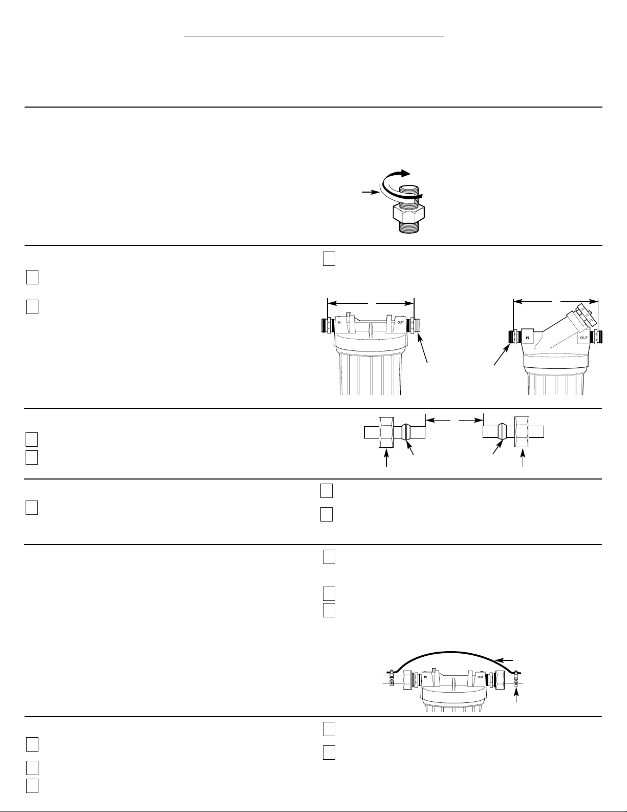
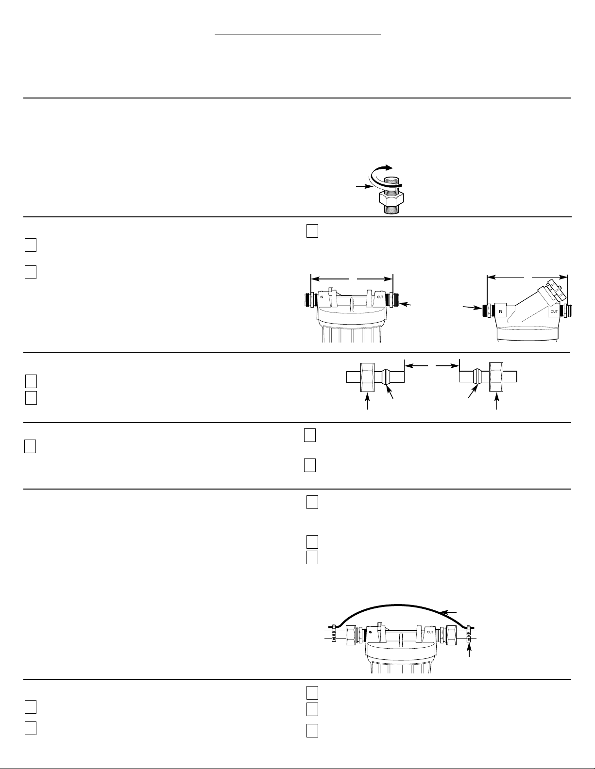
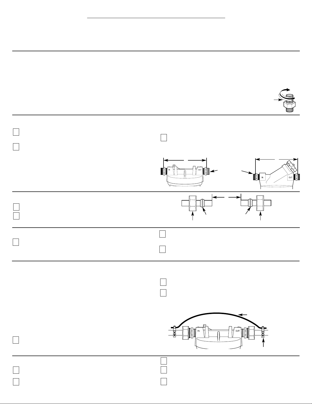
Install Fittings
Instructions are for installing fittings supplied with the
filter (on some models) or the WHKIT onto 3/4″ copper
plumbing. If the unit is to be installed on any other type of
tubing (plastic, PVC, galvanized), different hardware must be
purchased. See instructions with additional hardware
purchased, or consult a qualified plumber.
Apply about 6″ of Teflon®tape, in a clockwise direction, to
the pipe threads (course) of each adapter. DO NOT use joint
compound on any parts.
Assemble an adapter to the inlet and outlet of the head.
Start each fitting by hand to make sure they don’t cross
thread. Use a 1
1
⁄8″ wrench firmly. DO NOT OVERTIGHTEN.
About one to two thread(s) should remain visible.
Cut Water Line
Turn off water supply and open a nearby faucet to drain
water out of pipes.
Remove the nut and brass ferrule from both compression
fittings and set aside. Using a tape measure or ruler,
measure the distance “D” as shown.
■ NOTE: I
t is recommended that the shut-off valve be placed
before and after the filter as shown in the Installation
Overview illustration.
■ Select the location for the filter. Mark the distance “D”
on the pipe.
Using a pipe cutter or hacksaw, cut pipe. Sand (file) cut
ends of pipe to assure that they are square and smooth.
3
2
1
Attach Fittings to Water Line
Slip a compression nut onto each pipe.
Next, slip the brass ferrule onto each pipe.
2
1
Nut
Brass ferrule
Nut
Brass ferrule
Measure to shoulder
of fittings. Copper
pipe butts against
this shoulder.
D
D
GXWH01C
GXWH08C
Installing the Ground Wire
IMPORTANT: A copper or galvanized house cold water pipe is often
used to ground electrical outlets in the home. Grounding protects you
from electrical shock. The water filter housing may have broken this
ground path. To restore connection, install a 12″ long, 8-gauge
copper wire across the filter, tightly clamped using UL-approved
1/2″–1″ bronze grounding clamps at both ends as shown. Zinc
clamps should not be used on copper plumbing. For GXWH01C,
wire and clamps may be purchased separately from your local
hardware store, or are available by visiting our Website at
www.GEAppliances.com, or from Parts and Accessories by calling
800.626.2002 (U.S.)or 800.663.6060 (Canada) – order part
number WHKIT.
Clean copper pipe and ends of wire with emery paper. Bare wire
is recommended. If insulated wire is used, it should be stripped
3/4″ at each end before cleaning with emery paper.
Attach bronze clamps to copper pipe. Tighten screws.
Attach wire to clamps as shown. Tighten screws.
NOTE: If your house plumbing is plastic, it would not be used as a
grounding path, and this step should be skipped.
3
2
1
Clamp
Final Check
Install filter, if not all ready done. (See Filter Cartridge
Replacement section.)
Slowly turn on water supply.
Check entire system for leaks.
If leaking, shut off water pressure and tighten or reseal
fittings.
Open any downstream faucet and allow filter system to
flush for 5 minutes.
5
4
3
2
1
D
Ground wire
Teflon®tape
Installing the Unit
Align filter assembly with pipe ends making certain that the
incoming water supply is going into the filter opening marked
“IN”. It may be necessary to spread the pipe ends apart to install
filter assembly.
Using a 1
1
⁄8″ wrench to hold the adapter in place, use a 11⁄4″
wrench to tighten the nut. Repeat process for other fittings.
If necessary, support the water pipe on either side of the filter
unit.
3
2
1
Page 4
4
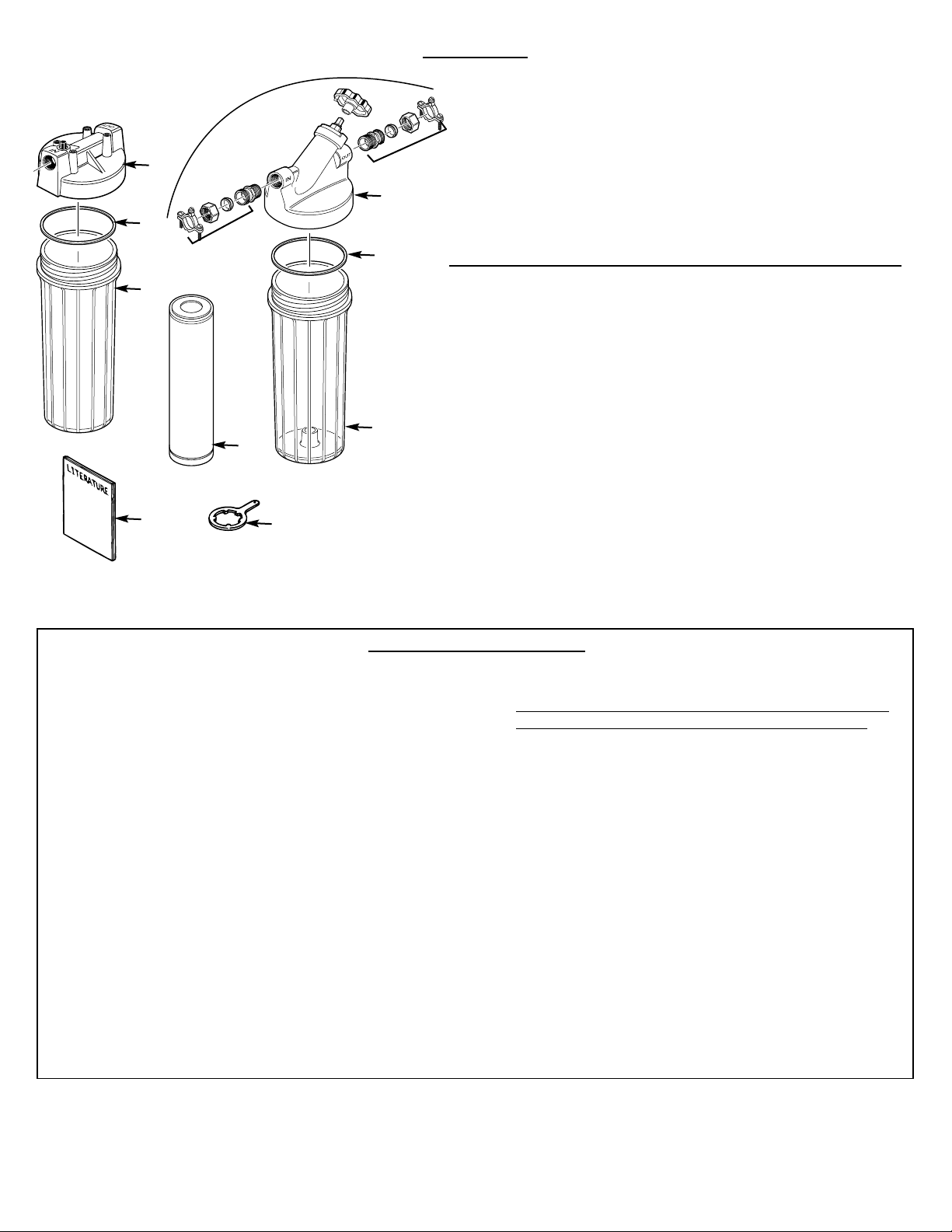
PARTS LIST
GG
XX
WW
HH
00
18
Ref. No. Part No. Part Description C C
001 WS35X10023 Installation Kit — 1
or WHKIT
002 WS19X10012 Head Assembly with Vent 1 —
WS19X10013 Head Assembly with Valve Assy. — 1
003 WS03X10038 O-Ring 1 1
004 WS30X10003 Sump–White 1 —
WS30X10004 Sump–Clear — 1
005 WX5X140 Sump Wrench — 1
006 FXUSC Filter Element–Poly Spun — 1
FXWPC Filter Element–Pleated — —
FXWSC Filter Element–String — —
FXWTC Filter Element–Carbon Paper — —
999 49-50043 PM Installation Instructions 1 1
999
006
004
004
003
003
002
002
001
001
005
To obtain replacement parts, call toll-free 800.626.2002 (U.S.),
800.663.6060 (Canada–English), 800.361.3869 (Canada–French).
LIMITED ONE-YEAR WARRANTY
• What does this warranty cover?
– Any defect in materials or workmanship in the
manufactured product.
• What does this warranty not cover?
– Filter Cartridges
– Service trips to your home to teach you how to use the
product
– Improper installation
– Failure of the product if it is abused, misused, altered or
used for other than the intended purpose
– Defects that result from improper installation or damage
not caused by GE
– Liability on the part of GE under this or any other
warranty for any indirect or consequential damage
– Products that are used for commercial or industrial
applications
– Use of this product where water is microbiologically
unsafe or of unknown quality, without adequate
disinfection before or after the system. Systems certified
for cyst reduction may be used on disinfected water that
may contain filterable cysts.
– Damage to the product caused by accident, fire, floods
or acts of God.
– Incidental or consequential damage caused by possible
defects with this appliance, its installation or repair.
• For how long after the original purchase?
– One Year.
• How do I make a warranty claim?
– Return to the retailer from which it was purchased along
with a copy of the “Proof of Purchase.” This warranty
excludes the cost of shipping or service calls
to your home.
• How does state law relate to this warranty?
– This warranty gives you specific legal rights, and you may
also have other rights which vary from state to state.
THIS WARRANTY IS INTENDED TO BE IN LIEU OF
ALL OTHER WARRANTIES, WHETHER EXPRESS OR
IMPLIED, INCLUDING THE WARRANTIES OF
MERCHANTABILITY AND FITNESS FOR A
PARTICULAR PURPOSE.
Contact us at www.GEAppliances.com, or call 800.GE.CARES
(U.S.), or toll-free 866.777.7627 (Canada).
Page 5

OUTILLAGE ET ACCESSOIRES REQUIS
POUR L’INSTALLATION
■
2 clefs : 11⁄8 po et 11⁄4 po
■
Coupe-tuyau ou scie à métaux
■
Lime
■
Papier Émeri
■
Tournevis
■
Pour le modèle GXWH01C, il peut être nécessaire
d’avoir des accessoires complémentaires :
• (2) adaptateurs de compression de
3
⁄
4 po avec bague
d’extremite et écrou pour le montage sur tuyau en
cuivre – Trousse d’installation disponible :
– Ensemble disponible (WHKIT)
– Pièces GE (WS35X10023)
• Attaches de mise à la masse homologuées UL et fil
de mise à la masse en cuivre de calibre 8 – Trousse
d’installation disponible :
– Ensemble disponible (WHKIT)
– Pièces GE (WS35X10023)
• Ruban en Téflon
®
• Clef pour puisard
– Ensemble disponible (UCWRNCH)
– Pièces GE (WX5X140)
Les accessoires en option sont disponibles. (cartes Visa,
Mastercard ou Discovery acceptées) en visitant notre site Web à
www.GEAppliances.com ou en vous adressant à notre service des
Pièces et Accessoires au 800.626.2002 (aux Etats-Unis) ou
800.361.3869 (en Canada).
■
Si l’appareil est installé sur une tuyauterie en plastique,
PVC ou métal galvanisé, il sera nécessaire d’acheter du
matériel distinct.
ARTICLES FOURNIS AVEC LE PRODUIT
■ Corps de filtre et tête de filtre
■ Brochures descriptives
■ Filtre à sédiments (pour GXWH08C)
■
2 raccords d’adaptation à compression 3⁄4po, avec écrou et
virole de laiton (pour GXWH08C)
■
Ruban de Teflon®(pour GXWH08C)
■
Clé pour corps de filtre (pour GXWH08C)
■
Brides et conducteur de liaison à la terre (pour GXWH08C)
1
GE SmartWater
™
INSTRUCTIONS D’INSTALLATION
Systèmes de filtration d’eau (usage domestique) — GXWH01C et GXWH08C
251B6021P001 10-01 49-50043-3
www.GEAppliances.com
GENERAL ELECTRIC COMPANY, Appliance Park, Louisville, KY 40225
MESURES DE SÉCURIT
É
■
Consulter le service local des travaux publics au sujet
des codes de plomberie et de raccordement aux égouts.
L’installation du système de filtration d’eau doit être
conforme aux prescriptions du code de plomberie local.
On recommande qu’un installateur qualifié soit chargé
de l’installation.
■
Vérifier que l’eau à traiter est conforme aux Conditions
d’utilisation–Spécifications. Si les caractéristiques de l’eau à
traiter ne sont pas connues, contacter le service municipal
de distribution d’eau.
AVERTISSEMENT :
Ne pas utiliser ce produit avec de l’eau
microbiologiquement polluée ou de qualité inconnue sans
avoir installé un dispositif de désinfection approprié avant
ou après le système.
■
On recommande fortement l’installation d’un robinet
d’arrêt directement en amont du système de filtration.
INSTRUCTIONS D’INSTALLATION
■ Consulter le service local des travaux publics au sujet des
codes de plomberie. L’installation du système de filtration d’eau
doit être conforme aux prescriptions du code de plomberie local.
■ Utiliser le système de filtration d’eau uniquement sur une
canalisation d’eau potable FROIDE. Les cartouches de filtration
ne purifient pas l’eau et ne peuvent rendre potable une eau qui
ne l’est pas. NE PAS utiliser ce produit sur une canalisation
d’eau CHAUDE (100
°
F maximum).
■ Protéger le système de filtration d’eau et la tuyauterie contre
le gel. La congélation d’eau dans le système lui fera subir des
dommages.
■ Le système de filtration d’eau peut résister à une pression
maximale de 125 lb/po
2
. Si la pression de distribution locale est
supérieure à 100 lb/po
2
durant la journée (elle peut atteindre un
niveau plus élevé la nuit), installer un robinet de réduction de
pression en amont du système de filtration d’eau.
■
Ne pas installer le système sur une canalisation D’EAU
CHAUDE. La température de l’eau à filtrer doit être située
entre 40
°
F (minimum) et 100°F (maximum). Voir les
Conditions d’utilisation–Spécifications.
■ Lors de l’installation du système de filtration d’eau, ne pas
utiliser des raccords de cuivre à souder. La chaleur émise
lors de l’opération de soudage fera subir des dommages
au système.
AVERTISSEMENT :
Éliminer en sécurité les petites
pièces qui peuvent rester inutilisées après l’installation;
elles peuvent susciter un danger d’étouffement pour les
jeunes enfants.
■ Ne pas installer le filtre à l’extérieur ou à un endroit exposé
au rayonnement solaire.
Avant toute utilisation, on doit installer le système de filtration d’eau (usage domestique) soit à un emplacement adéquat
conformément aux instructions d’installation.
Ce système a été testé et homologué par
NSF International selon la norme ANSI/NSF
42, pour réduction nominale de la
concentration de particules, classe III.
Ce système a été testé et homologué par
NSF International selon la norme ANSI/NSF
42, pour réduction nominale de la
concentration de particules, classe III.
GXWH01C
GXWH08C
Page 6
2
LA CARTOUCHE DE FILTRATION
Remplacement de la cartouche de filtration
On doit changer la cartouche de filtration lorsque le débit d’eau diminue sensiblement, et au moins à
intervalles de trois mois.
Longévité des cartouches de filtration
La longévité en service des cartouches de filtration
du système dépend de diverses variables comme :
■
concentration de sédiments et autres substances
indésirables.
■
volume de consommation d’eau.
■
type d’utilisation (filtration de la totalité ou d’une
partie seulement de l’eau consommée).
MODÈLE GE FONCTION LONGÉVITÉ MATÉRIAU
FXUSC Sédiments 3 mois/16 000 gallons Bobinage de
15 microns polyester
FXWPC Sédiments 3 mois/16 000 gallons Plissage
FXWSC Sédiments 3 mois/16 000 gallons Bobinage
10 microns
FXWTC Sédiments 3 mois/15 000 gallons Carbone/papier
5 microns
Chlore
*La Certification NSF pour une réduction particulière est applicable seulement au FXUSC
et au FXWTC lorsqu’utilisés dans les systèmes de filtration GXWH01C ou GXWH08C.
Fermer l’arrivée d’eau au filtre. Pour le modèle
GXWH01C, on doit fermer le robinet d’arrêt
en amont. Pour le modèle GXWH08C, placer le
robinet de dérivation à la position «dérivation».
Dépressuriser le système : appuyer sur le
bouton rouge.
Dévisser le corps de filtre; jeter la vieille
cartouche. Laver le corps de filtre avec de
l’eau et un savon doux. Ne pas utiliser de l’eau
chaude ou un produit de nettoyage énergique.
Inspecter le joint torique du corps de filtre.
Veiller à ce qu’il soit légèrement lubrifié et
bien emboîté dans la rainure. Remplacer le
joint torique s’il est endommagé.
Placer la nouvelle cartouche de filtration dans
le corps de filtre; placer correctement et bien
centrer la cartouche sur le joint du fond.
Revisser le corps de filtre sur la tête. Il suffit de
serrer à la main.
Rétablir lentement l’arrivée d’eau au filtre avec
le robinet de dérivation (modèle GXWH08C)
ou le robinet d’arrêt en amont.
Appuyer sur le bouton rouge pour permettre
l’évacuation de l’air piégé.
Ouvrir un robinet en aval, et effectuer un
rinçage du système pendant 5 minutes.
9
8
7
6
5
4
3
2
1
Illustration de l’installation
NOTE : Veiller à ce qu’il y ait un espace libre d’au
moins 11⁄2po sous le filtre pour l’extraction du corps
de filtre lors du changement de la cartouche.
Utiliser l’outil spécial
pour dévisser le corps
de filtre–rotation
dans le sens horaire
(certains modèles)
Corps de filtre
Robinet de
dérivation
Cartouche
de filtration
Joint torique
Bouton rouge de
dépressurisation
Tête
Corps de filtre
Dévissage–
rotation dans
le sens horaire
Vissage–
rotation dans le
sens antihoraire
Dévissage–
rotation dans
le sens horaire
Vissage–
rotation dans le
sens antihoraire
Bouton rouge de
dépressurisation
Cartouche
de filtration
Joint torique
Corps de filtre
Tête
GXWH01C
GXWH08C
Robinet d’arrêt–
recommandé
Robinet d’arrêt–
recommandé
GXWH01C
GXWH08C
Conditions d’utilisation—Spécifications
Pression de distribution de l’eau (minimum-maximum) : 20-125 livres/po
2
Température de l’eau (minimum-maximum) : 40
°F
/100
°
F Débit nominal en service : 4 gal./min
Robinet d’arrêt–
recommandé
Robinet d’arrêt–
recommandé
ÉTAPES DE L’INSTALLATION
Page 7
3
ÉTAPES DE L’INSTALLATION (suite)
Emplacement d’installation
Choisir l’emplacement approprié comme suit :
■
pas d’exposition au gel.
■
pas d’exposition au rayonnement solaire direct.
On recommande d’installer un robinet d’arrêt de chaque
côté du filtre.
Pose des raccords
Les instructions sont destinées à l’installation des raccords
fournis avec le filtre (pour certains modèles) ou le WHKIT à la
tuyauterie en cuivre de 3/4 po. Si le matériau de la canalisation
est différent (plastique, PVC, acier galvanisé), il sera nécessaire
de faire l’achat de quincaillerie différente.
Voyez les instructions
couvrant le matériel complémentaire acheté ou consultez un
plombier qualifié.
Enrouler environ 6 po de ruban de Teflon®(sens horaire) sur le
filetage de chaque raccord d’adaptation. NE PAS utiliser un
composé d’étanchéité.
Installer une adaptateur sur la tête du filtre, à l’entrée et à
la sortie. Commencer le vissage à la main et veiller à ne pas
détériorer le filetage. Serrer ensuite avec une clé de 1
1
⁄8 po.
NE PAS SERRER EXCESSIVEMENT.
Un filet ou deux doivent rester visibles.
Sectionnement de la canalisation d’eau
Fermer l’arrivée d’eau; ouvrir un robinet pour purger l’eau
des tuyauteries.
Conserver à part l’écrou et la virole de laiton des raccords
à compression. À l’aide d’un ruban-mètre ou d’une règle,
mesurer la distance «D» indiquée sur l’illustration.
■ NOTE : On recommande d’installer un robinet d’arrêt avant
et après le filtre–voir l’illustration de l’installation.
■ Choisir l’emplacement d’installation du filtre. Marquer la
distance «D» sur la tuyauterie.
Avec un coupe-tuyau ou une scie à métaux, couper la
canalisation. Poncer à chaque extrémité pour éliminer
les bavures.
3
2
1
Installation des raccords sur la canalisation
Sur chaque tuyau, enfiler l’écrou de compression.
Enfiler ensuite la bague d’extremite sur chaque tuyau.
2
1
Écrou
Bague d’extremite
Écrou
Bague d’extremite
Mesurer jusqu’à
l’épaulement du raccord.
La canalisation de cuivre
vient en butée contre cet
épaulement.
D
D
GXWH01C
GXWH08C
Installation du conducteur de liaison à la terre
IMPORTANT : Fréquemment, on utilise un tuyau d’eau
froide en cuivre ou en métal galvanisé pour effectuer une
liaison à la terre des prises électriques de la maison. Cette mise
à la masse vous protège contre les chocs électriques et cette
liaison à la terre peut voir été neutralisée par le logement du
filtre d’eau. Pour rétablir la connexion, montez un fil en
cuivre de 12poet de calibre 8 le long du filtre, lequel sera
fixé solidement au moyen d’attaches en bronze homologuées
par UL de dimensions variant entre 1/2po– 1poà chaque
extrémité comme indiqué. N’utilisez pas d’attaches en zinc
sur le cuivre. Pour le modèle GXWH01C, il est possible
d’acquérir le fil et les attaches séparément chez votre visitant
notre site Web à www.GEAppliances.com ou en vous adressant
à notre service des Pièces et Accessoires au 800.626.2002 (aux
Etats-Unis) ou 800.361.3869 (En Canada). Commandez la
pièce portant le numéro WHKIT.
Nettoyez le fil en cuivre et ses extrémités avec du papier
Émeri. Il est recommandé de dénuder le fil. Si le fil est
isolé, il faut le dénuder sur une longueur de 3/4 po à
chaque extrémité avant de les passer au papier Émeri.
Placez les attaches en bronze sur le fil. Serrez les vis.
Fixez le fil sur les attaches comme indiqué. Serrez les vis.
NOTE : Si les tuyauteries de votre domicile sont en plastique,
elles ne peuvent être utilisées pour une liaison à la terre, dans
ce cas, ignorez cette étape.
3
2
1
Bride
Contrôle final
Installez le filtre si vous ne l'avez pas encore fait. (Voir la
partie de Remplacement de la cartouche de filtre).
Ouvrir doucement l’arrivée d’eau.
Inspecter l’ensemble du système pour rechercher les fuites.
S’il y a une fuite, fermer l’arrivée d’eau et resserrer les
raccords ou améliorer leur étanchéité.
Ouvrir un robinet en aval, et effectuer un rinçage du système
pendant 5 minutes.
5
4
3
2
1
D
Conducteur de liaison à la terre
Ruban de Teflon
®
Installation du filtre
Aligner le filtre avec les deux sections de la canalisation;
veiller à ce que la canalisation d’arrivée soit placée devant
l’entrée du filtre, marquée «IN». Il peut être nécessaire
d’écarter les deux sections de la tuyauterie pour installer le
filtre.
Immobiliser le raccord avec une clé de 11⁄8po, et serrer
l’écrou avec une clé de 1
1
⁄
4
po. Répéter ceci pour chaque
raccord.
Si nécessaire, soutenir la tuyauterie d’eau de chaque côté
du filtre.
3
2
1
Page 8

4
LISTE DES PIÈCES
999
006
004
004
003
003
002
002
001
001
005
GG
XX
WW
HH
00
N
o
de 1 8
repérage Pièce n
o
Description C C
001 WS35X10023 Pièces de raccordement — 1
ou WHKIT
002 WS19X10012 Tête du filtre, avec évent 1 —
WS19X10013 Tête du filtre, avec robinet — 1
003 WS03X10038 Joint torique 1 1
004 WS30X10003 Corps de filtre–blanc 1 —
WS30X10004 Corps de filtre–transparent — 1
005 WX5X140 Clé pour corps de filtre — 1
006 FXUSC Cartouche de filtration– — 1
polyester bobiné
FXWPC Cartouche de filtration–plissée — —
FXWSC Cartouche de filtration–bobine — —
FXWTC Cartouche de filtration– — —
carbone/papier
999 49-50043 Instructions d’installation et 1 1
d’utilisation
Pour obtenir des pièces de rechange, composez sans frais le 800.626.2002
(États-Unis), le 800.663.6060 (Canada, langue anglaise), le 800.361.3869
(Canada, langue française).
GARANTIE LIMITEE DE UN AN
• Que couvre la garantie?
– Tout défaut de matériel ou de main d’oeuvre du produit
• Q’est-ce qui n’est pas couvert par la garantie?
– Les cartouches de filtre
– Les déplacements à votre domicile pour vous enseigner
comment utiliser le produit
– Une installation incorrecte
– Une panne du produit causée par un abus d’utilisation,
une mauvaise utilisation, toute modification ou une
utilisation du produit dans un but non prévu
– Défauts entraînés par une installation incorrecte ou tout
dommage non imputable à GE
– Responsabilité de GE couvert par cette garantie ou toute
autre garantie couvrant tout dommage indirect
– Produits utilisés pour des applications industrielles ou
commerciales
– Utilisation de ce produit lorsque l’eau est
microbiologiquement impure ou de qualité inconnue
sans qu’une désinfection adéquate n’ait eu lieu avant
l’entrée et sortie dans le circuit. Les systèmes
homologués pour une réduction des microbes
peuvent être utilisés après désinfection de l’eau pouvant
contenir des microbes filtrables.
– Tout dommage causé au produit par accident, incendie,
inondation ou acte de Dieu
– T
out dommage fortuit ou indir
ect causé par des défauts
éventuels de cet appareil, son installation ou les
réparations effectuées
• Quelle est la durée de la garantie après l’achat?
– Un an.
• Comment dois-je faire ma réclamation?
– Ramenez le produit au magasin où vous l’avez acheté
avec une exemplaire de la “Preuve d’achat”. Cette
garantie exclut les coûts d’expédition ou les
déplacements de service à votre domicile.
• Quel est le statut de cette garantie vis-à-vis de la loi?
– Cette garantie vous donne des droits légaux spécifiques.
Il est possible que vous ayez d’autres droits qui varient
d’état en état. CETTE GARANTIE REMPLACE DE
TOUTE AUTRE GARANTIE, QU’ELLE SOIT
EXPRIMEE OU SOUS-ENTENDUE, INCLUANT LES
GARANTIES DE NEGOCE ET DE CONVENANCE
DANS UN BUT PARTICULIER.
Veuillez nous contacter à www.GEAppliances.com, ou composez
le 800.GE.CARES (États-Unis) et sans frais le 866.777.7627
(Canada).
Page 9

HERRAMIENTAS Y ACCESSORIOS QUE SE NECESITAN PARA LA INSTALACION
■
2 llaves inglesas: 11⁄8″ y11⁄4″
■
Cortador de tubos o sierra para metales
■
Lima
■
Papel de esmeril
■
Destornillador
■
Para el modelo GXWH01C, es posible que se necesite
partes adicionales para completar la instalación:
• (2) 3⁄4″ adaptadores de compresión con férula de
bronce y tuercas para instalar en tuberías de cobre.
El kit para la instalación está disponible:
– Venta al por menor, parte (WHKIT)
– Partes de GE (WS35X10023)
• Abrazaderas de toma de tierra aprobadas por UL y
cable de toma de tierra de cobre calibre 8. El kit
para la instalación está disponible:
– Venta al por menor, parte (WHKIT)
– Partes de GE (WS35X10023)
• Cinta de teflón
®
• Llaves inglesas para sumideros
– Venta al por menor, parte
(UCWRNCH)
– Partes de GE (WX5X140)
Los accesorios opcionales están disponibles (usando Visa,
MasterCard o Discover) visitando nuestro Website a
www.GEAppliances.com o en el Departamento de Partes
y Accesorios en el 800.625.2002.
■
Si la unidad es para ser instalada en plástico, pvc, o
tubería galvanizada, deberá comprar por separado
más herramientas
CONTENIDOS INCLUIDOS CON EL PRODUCTO
■ Caja y cabeza del filtro
■ Literatura del producto
■ Filtro para sedimento
(para GXWH08C)
■
(2) adaptadors uniones de compresión de bronce de 3⁄4″
con tuerca y férula (para GXWH08C)
■ Cinta de teflón®(para GXWH08C)
■
Llave para el receptáculo (para GXWH08C)
■
Abrazadera y alambre para hacer tierra (para GXWH08C)
El sistema está probado y certificado por
NSF International contra las Normas 42 de
ANSI/NSF
para reducción de partículas
nominativas Class III.
1
GE SmartWater
™
INSTRUCCIONES DE INSTALACION
Sistema de filtración de agua para el hogar — GXWH01C y GXWH08C
251B6021P001 10-01 JR 49-50043-3
www.GEAppliances.com
GENERAL ELECTRIC COMPANY, Appliance Park, Louisville, KY 40225
PRECAUCIONES DE SEGURIDAD
■
Consulte con su departamento de obras públicas local y
estatal para los códigos de plomería y sanidad. Usted debe
seguir estas reglas a medida que instale el sistema de
filtración de agua para el hogar. El uso de un instalador
calificado es recomendado.
■
Asegúrese que el abastecimiento de agua cumple con
las Guías de Especificaciones. Si las condiciones del
abastecimiento de agua son desconocidas, póngase
en contacto con su compañía de agua municipal.
ADVERTENCIA: No use con agua que sea
bacteriológicamente insegura o de calidad desconocida
sin una desinfección adecuada antes o después del sistema.
■
Es altamente recomendado que la válvula de cierre sea
colocada directamente hacia arriba de su filtro de hogar.
INSTALACION CORRECTA
■ Consulte con su departamento de obras públicas local para los
códigos de plomería. Usted debe seguir sus guías a medida que
instale el sistema de filtración de agua para el hogar.
■ Use el sistema de filtración de agua para el hogar solamente en
un abastecimiento de agua potable fría de hogar, que sea buena
para beber. El cartucho del filtro no purificará el agua o hará
que el agua que no sea buena sea potable. NO use en agua
caliente (100°F máx.).
■ Proteja el sistema de filtración de agua para el hogar y las
cañerías de la congelación. El que se congele en el sistema
lo dañará.
■ Su sistema de filtración de agua para el hogar soportará hasta
124 psi de presión de agua. Si la presión de agua de su casa es
más de 100 psi durante el día (podría alcanzar niveles más altos
durante la noche), instale una válvula para reducir la presión
antes de que el sistema sea instalado.
■
No instale en AGUA CALIENTE. La temperatura de la línea
de agua hacia el sistema de filtración de agua para el hogar
debe estar entre el mínimo de 40°F, y el máximo de 100°F.
Vea las Guías de Especificaciones.
■ No instale el sistema de filtración de agua para el hogar
usando uniones de cobre soldadas. El calor del proceso de
las soldaduras dañará la unidad.
ADVERTENCIA:
Bote todas las partes y los materiales
de empaque sin usar después de la instalación. Las partes
pequeñas que sobren después de la instalación podrían ser
un peligro para atragantarse.
■ No instale el filtro en una ubicación exterior o en un lugar
donde esté expuesto a la luz del sol.
Este sistema de filtración de agua para el hogar debe ser instalado y ubicado correctamente de acuerdo con las instrucciones de
instalación antes de ser usado.
GXWH01C
GXWH08C
El sistema está probado y certificado por
NSF International contra las Normas 42 de
ANSI/NSF
para reducción de partículas
nominativas Class III.
Page 10

2
LOS CARTUCHOS DEL FILTRO
Reemplazo del cartucho del filtro
Usted debería cambiar el filtro cuando el paso del agua disminuye notablemente o por lo menos cada tres meses.
Vida del cartucho del filtro
Varias variables determinan cuánto tiempo
durará el cartucho en su sistema de filtración de
agua para el hogar. Estos incluyen:
■
niveles de sedimento u otras sustancias
indeseables en su agua.
■
la cantidad de agua que use.
■
la ubicación del filtro (filtrando toda o parte
del agua del hogar).
MODELO GE FUNCION VIDA CONSTRUCCION
FXUSC Sedimento 3 meses/16.000 galones Polyspun
15 micrones
FXWPC Sedimento 3 meses/16.000 galones Plegado
FXWSC Sedimento 3 meses/16.000 galones Enrollado con hilos
10 micrones
FXWTC Sedimento 3 meses/15.000 galones Papel carbón
5 micrones
Cloro
*La Certificación NSF para reducción de partículas se aplica solamente en FXUSC y FXWTC
cuando son usados en Sistemas de Filtración GXWH01C ó GXWH08C.
Cierre el paso del agua al filtro. Para el
modelo GXWH01C, el agua se debe cerrar
en una válvula paso arriba. Para el modelo
GXWH08C, haga rotar la válvula tipo
“bypass”a la posición “bypass”.
Empuje el botón rojo para reducir la presión
para bajar la presión.
Desatornille el receptáculo y bote el filtro
usado. Lave el receptáculo del filtro con un
jabón suave y agua. No use limpiadores
fuertes o agua caliente.
Inspeccione el anillo del receptáculo.
Asegúrese que esté levemente lubricado y
completamente asentado en la ranura.
Se recomienda que cambie el anillo si
está dañado.
Coloque un filtro nuevo en el receptáculo
asegurándose de que esté centrado y
completamente asentado sobre el fondo
del sello.
Reinstale el receptáculo del filtro a la unidad.
Apretarlo con la mano es todo lo que se
necesita para sellar la unidad.
Lentamente abra el paso del agua hacia
el filtro usando la válvula tipo “bypass”
(modelo GXWH08C) o en la válvula de
cierre paso arriba.
Empuje el botón rojo para reducir la presión
para sacar el aire atrapado.
Abra cualquier llave de agua hacia abajo y
permita que el sistema de filtración se lave
por 5 minutos.
9
8
7
6
5
4
3
2
1
Sumario de la instalación
NOTA: Asegúrese de dejar un espacio mínimo de
11⁄2″ debajo del filtro para sacar el esceptáculo,
para cambiar el cartucho.
Haga girar la llave para
el receptáculo en dirección
del reloj para sacarlo
(en algunos modelos)
Receptáculo
Válvula tipo
“bypass”
Cartucho
del filtro
Sello tipo anillo
Botón rojo
para reducir
la presión
Cabeza
Receptáculo
del filtro
Haga girar en
dirección del
reloj para sacar
el receptáculo
Haga girar
contra el reloj
para apretar
Haga girar en
dirección del
reloj para sacar
el receptáculo
Haga girar
contra el reloj
para apretar
Botón rojo
para reducir
la presión
Cartucho
del filtro
Sello tipo anillo
Receptáculo
del filtro
Cabeza
GXWH01C
GXWH08C
Válvula de cierre
recomendada
Válvula de cierre
recomendada
GXWH01C
GXWH08C
Guías de Especificaciones
Mínima-Máxima presión de abastecimiento de agua: 20-125 libras por pulgada cuadrada (psi)
Mínima-Máxima temperatura del abastecimiento de agua: 40°F/100°F Valor de paso de servicio: 4 gpm
Válvula de cierre
recomendada
Válvula de cierre
recomendada
INSTRUCCIONES DE INSTALACION PASO A PASO
Page 11
3
INSTRUCCIONES DE INSTALACION PASO A PASO (cont.)
Seleccione la ubicación
Seleccione una ubicación para el filtro que esté:
■
protegida de la congelación.
■
que no esté expuesta a la luz directa del sol.
Se recomienda instalar una válvula de cierre en ambos
lados del filtro.
Instalación de las uniones
Las instrucciones son para instalar los accesorios que han sido
proporcionados con el filtro (en algunos modelos) o la pieza
WHKIT en una tubería de cobre de 3/4″. Si la unidad va a ser
instalada con cualquier otro tipo de tuberías (plástico, PVC,
galvanizado), debe comprarse diferente tipo de herramienta.
Lea las instrucciones para la compra adicional de
herramientas, o consulte con un plomero calificado.
Aplique unas 6″ de cinta teflón®, en dirección del reloj, a los
hilos del tubo (curso) de cada adaptador. No use compuestos
para uniones sobre ninguna de las partes.
Arme un adaptador en la entrada y la salida de la cabeza.
Empiece cada unión con la mano para estar seguro que los
hilos no se crucen. Use una llave inglesa de 11⁄8″ firmemente.
NO APRIETE DEMASIADO. Uno o dos hilos deberían
permanecer visibles.
Corte de la línea de agua
Cierre el paso del agua y abra una llave de agua cercana
para sacar el agua de las cañerías.
Saque la tuerca y la férula de las dos uniones de
compresión y póngalas a un lado. Usando una cinta para
medir o una regla, mida la distancia “D” como se muestra.
■ NOTA: Se recomienda que la válvula de cierre sea colocada
antes y después del filtro como se muestra en la ilustración
Sumario de la Instalación.
■ Seleccione la ubicación para el filtro. Marque la distancia
“D” sobre el tubo.
Usando un cortador de cañerías o una sierra para cañerías,
corte el tubo. Lije (lime) las puntas cortadas para
asegurarse que estén cuadradas y suaves.
3
2
1
Conecte las uniones a la línea del agua
Deslice una tuerca de compresión en cada cañería.
Luego, deslice la férula de bronce en cada cañería.
2
1
Tuerca
Férula de bronce
Tuerca
Férula de bronce
Mida hasta el
hombro de la unión.
Puntas de cobre
contra este hombro
D
D
GXWH01C
GXWH08C
Instalación del cable de tierra
IMPORTANTE: Una tubería de agua fría galvanizada interiormente o de cobre
es usada muy a menudo para conectar a tierra los tomacorrientes eléctricos
en las casas. Una toma de tierra lo protege de descargas eléctricas. El
alojamiento del filtro de agua pudo haber interrumpido la trayectoria de
tierra. Para restablecer la conexión, instale un cable de cobre de 12″, de
calibre 8 a través del filtro, fuertemente sujeto utilizando abrazaderas de
tierra de bronce de 1/2″ a 1″ aprobada por UL en ambos extremos de la
línea como se muestra en la ilustración. Usted no debe usar abrazaderas de
cinc en tubería de cobre. Para el modelo GXWH01C,el cable y las
abrazaderas pueden ser compradas por separado en su ferretería local, o
están disponibles visitando nuestro Website a www.GEAppliances.com o en
nuestro Departamento de Partes y Accesorios al 800.626.2002 – ordene el
número de la parte WHKIT.
Limpie la tubería de cobre y los extremos del cable con papel de esmeril.
El cable debe ser por lo menos calibre 6 para un circuito de 200
amperios, calibre 8 para un circuito de 100 amperios. Se recomienda que
utilice cable desnudo. Si utiliza cable aislado, las puntas deberían estar
desnudas de su protector, aproximadamente 3/4″ antes de proceder a
limpiarlas con papel de esmeril.
Sujete las abrazaderas de bronce a la tubería de cobre. Apriete los
tornillos.
Sujete el cable a las abrazaderas tal como se muestra en la figura. Apriete
los tornillos.
NOTA: Si la tubería de su casa es de plástico no debería ser usada para
efectuar la conexión de tierra, y este paso puede ser obviado.
3
2
1
Abrazadera
Revisión final
Instale el filtro, si no lo ha hecho aún. (Vea la sección para
Reemplazo del cartucho del filtro).
Lentamente abra el paso del agua.
Revise todo el sistema para que no hayan goteras.
Si hay goteras, cierre la presión del agua o reselle las
uniones.
Abra cualquier llave de agua hacia abajo y permita que el
sistema de filtración se lave por 5 minutos.
5
4
3
2
1
D
Alambre para hacer tierra
Cinta de teflón
®
Instalación de la unidad
Ponga en línea el juego del filtro con las puntas de la cañería
asegurándose que
la entrada
de la línea del agua vaya hacia la abertura
marcada “IN”. Podría ser necesario abrir las puntas de las cañerías para
instalar el juego del filtro.
Usando una llave inglesa de 1
1
⁄8″ para sujetar el adaptador en su lugar,
use una llave inglesa de 11⁄4″ para apretar la tuerca. Repita el proceso
para las otras uniones.
Si es necesario, sujete la cañería de agua en cualquier lado de la unidad
del filtro.
3
2
1
Page 12

4
LISTA DE PARTES
006
004
004
003
003
002
002
001
001
005
GG
XX
WW
HH
00
No. 1 8
de ref. Parte No. Descriptión C C
001 WS35X10023 Juego de instalación — 1
o WHKIT
002 WS19X10012 Juego de la cabeza con ventilación 1 —
WS19X10013 Juego de la cabeza con — 1
juego de válvula
003 WS03X10038 Anillo 1 1
004 WS30X10003 Receptáculo–Blanco 1 —
WS30X10004 Receptáculo–Claro — 1
005 WX5X140 Llave para receptáculo — 1
006 FXUSC Elemento de filtro–Poly Spun — 1
FXWPC Elemento de filtro–Plegado — —
FXWSC Elemento de filtro–Hilos — —
FXWTC Elemento de filtro–Papel carbón — —
999 49-50043 Instrucciones de Instalación 1 1
Para obtener partes de repuesto llame sin costo al 800.626.2002 (EE.UU.),
800.663.6060 (Canadá–inglés), 800.361.3869 (Canadá–francés).
999
GARANTÍA LIMITADA POR UN AÑO
• ¿Qué cubre esta garantía?
– Cualquier defecto de fábrica en los materiales o la
manufactura del producto
• ¿Qué no cubre esta garantía?
– Cartuchos del filtro
– Viajes a su casa para enseñarle cómo usar el producto
– Instalación inadecuada
– Falla del producto debido a abuso, mal uso, o alteración
o uso diferente al propósito deseado con este producto
– Defectos que resulten de una instalación inadecuada o
daños no causados por GE
– Responsabilidad de parte de GE bajo esta o cualquier
otra garantía por cualquier daño indirecto o por
consecuencia de otro evento
– Productos que son usados con fines comerciales o
industriales
– Uso de este producto donde el agua está
microbiológicamente insegura o de calidad desconocida,
sin la adecuada desinfección, antes y después de ser
procesada por el sistema. Los sistemas certificados para
reducir el nivel de quistes pueden ser usados en agua
desinfectada que pueda contener quistes que se puedan
filtrar.
– Daños causados al producto debido a accidentes,
incendio, inundaciones o actos de la naturaleza.
– Daños secundarios o por consecuencia causados por
posibles defectos en el producto, su instalación o
reparación.
• ¿Por cuánto tiempo después de la compra?
– Un año
• ¿Cómo hago la reclamación de la garantía?
– Devuélvala al minorista a quien le compró el producto
con una copia de “Proof of Purchase”(prueba de
compra). Esta garantía excluye los costos de envío o
llamadas de servicio a domicilio.
• ¿Cómo la ley estatal se relaciona con esta reclamación de
garantía?
– Esta garantía le otorga derechos legales específicos, y
también puede tener otros derechos que varían de
estado a estado. ESTA GARANTÍA PROCURA
SUBSTITUIR OTRAS GARANTÍAS, HAYAN SIDO
ESTAS GARANTÍAS EXPRESADAS O IMPLICADAS,
INCLUYENDO LAS GARANTÍAS DE MERCADEO Y
APTAS PARA UN PROPÓSITO EN PARTICULAR.
Contáctenos en www.GEAppliances.com, o llame al
800.GE.CARES (EE.UU.), llamada sin costo 866.777.7627 (Canada).
 Loading...