

Page 1

www.GEAppliances.com
Water Filtration System
La section française commence à la page 17
La sección en español empieza en la página 33
GXSL03C (rev. 2) is
Tested and
Certified by NSF International
against ANSI/NSF
Standard 42
for the reduction of Particulate
Class I, Chlorine and Taste/Odor
and Standard 53 for the
reduction of Lead, Mercury, Cyst,
Turbidity, Asbestos, Atrazine and
Lindane.
GXSV10C is
Tested and Certified
by NSF International against
ANSI/NSF
Standard 42 for the
reduction of Particulate Class I,
Chlorine and Taste/Odor and
Standard 53 for the reduction of
Lead, Mercury, Cyst, Turbidity,
Asbestos and VOC.
Safety Information . . . . . . . . .2
Operating Instructions . . .3, 4
Specification Guidelines . . . . . . . . . . .3
Using the System . . . . . . . . . . . . . . . .4
Installation
Instructions . . . . . . . . . . . . .5–11
Battery Pack Installation . . . . . . . . . . .8
Faucet Installation . . . . . . . . . . . . . .7, 8
Feed Water Supply . . . . . . . . . . . . . . .6
Filter Cartridge Installation
or Replacement . . . . . . . . . . . . . .10, 11
Flush Procedure . . . . . . . . . . . . . . . .11
Important Recommendations . . . . . . .5
Step-by-Step Instructions . . . . . . . .7–9
Tools/Materials Required . . . . . . . . . .5
Tubing Connections . . . . . . . . . . . . . . .9
Wall Mounting . . . . . . . . . . . . . . . . . .9
Troubleshooting Tips
Before You Call For Service
. . . . . . . .12
Consumer Support
Consumer Support . . . . . . . . . . . . . . .16
Parts List/Catalog . . . . . . . . . . . . . . .13
Warranty . . . . . . . . . . . . . . . . . . . . . .16
Write the model and serial
numbers here:
Model # ______________
Serial # ______________
You can find them on the
sump bracket.
215C1044P009-3 49-50039-3 05-02 JR
7238769
GXSL03C (rev. 2)
GXSV10C
Owner’s Manual
and Installation
Instructions
Page 2

SAVE THESE INSTRUCTIONS
READ AND FOLLOW THIS SAFETY INFORMATION CAREFULLY.
■
Install or store where it will not be exposed to temperatures
below freezing or exposed to any
type of weather. Water
freezing in the system will damage it. Do not attempt to treat
water over 100°F.
WARNING: Discard all unused and packaging
material after installation. Small parts remaining after
installation could be a choke hazard.
■
Your Water Filtration system will withstand up to 125 pounds
per square inch (psi) water pressure. If your house water
supply pressure is higher than 100 psi, install a pressure
reducing valve before installing the Water Filtration system.
IMPORTANT SAFETY INFORMATION.
READ ALL INSTRUCTIONS BEFORE USING.
For your safety, the information in this manual must be followed to minimize the risk of
property damage or personal injury.
SAFETY PRECAUTIONS
■
Check with your local public works department for
plumbing codes. You must follow these guidelines as you
install the Water Filtration system.
■ Use the Water Filtration system on a potable, safe-to-drink,
home COLD water supply only. The filter cartridges will not
purify the water, or make it safe to drink.
■ Do not use on a hot water supply (100°F max.)
.
WARNING: Do not use with water that is
microbiologically unsafe or of unknown quality without
adequate disinfection before or after the system. Systems
certified for cyst reduction may be used on disinfected
water that may contain filterable cysts.
PROPER INSTALLATION
This Water Filtration system must be properly installed and located in accordance with the Installation Instructions
before it is used.
2
WARNING!
Page 3

3
Specification guidelines. www.GEAppliances.com
Many bad tastes and/or odors are removed from water using activated carbon
filter cartridges. They are most often used to remove a chlorine taste and odor.
They can also reduce other undesirable elements from drinking water supplies,
such as organic chemical contaminants and lead.
NOTE: Small amounts of hydrogen sulfide (noticeable as “rotten egg” odor) may
be reduced by taste and odor filters for a short time, but the carbon media is
quickly exhausted. Other water conditioning equipment is usually required for
the continuous treatment of hydrogen sulfide.
For Model GXSL03C (rev. 2)
FXSLC (rev. 2) Filter Set
(600-Gallon Capacity)
Filter I – White with no
end caps
Filter II – White with
yellow end caps
• Reduces dirt, rust and
sediment
• Reduces unpleasant
tastes and odors
• Reduces Chlorine:
Taste and Odor
• Reduces Lead
• Reduces Asbestos
• Reduces Mercury
• Reduces Atrazine
• Reduces filterable cysts
(such as
cryptosporidium
and giardia)
• Reduces Lindane
(a pesticide)
• 0.5–1 micron nominal
particulate reduction
For Model GXSV10C
FXSVC (rev. 2) Filter Set
(600-Gallon Capacity)
Filter I – White with
green end caps
Filter II – Gray
• Reduces dirt, rust and
sediment
• Reduces unpleasant
tastes and odors
• Reduces Chlorine:
Taste and Odor
• Reduces Lead
• Reduces Asbestos
• Reduces Mercury
• Reduces filterable cysts
(such as
cryptosporidium
and giardia)
• Reduces Volatile
Organic Chemicals
(VOCs)
• 0.5–1 micron nominal
particulate reduction
Minimum - Maximum Supply Water Pressure – 40–125 pounds per square inch (psi)
Minimum - Maximum Supply Water Temperature – 40°–100°F
Inlet - Outlet – 3/8 ″ NPT, fittings and tubing included
Rated Service Flow – 0.6 gpm (GXSL03C [rev. 2])
0.6 gpm (GXSV10C)
Depending on the treatment needed for a specific water supply, the water filtration system
can be customized using any combination of the preceding filter cartridge sets.
The Water Filtration system uses two filter cartridges.
This system conforms to ANSI/NSF 42 and 53 for the specific performance
claims as verified and sustained by test data.
Page 4

About the water filtration system.
Using the Water Filtration System and About the Filter Cartridge
The countertop faucet dispenses filtered drinking water when opened.
It has a hand-operated, spring-loaded closed lever to prevent waste. You can
keep the faucet open by pushing upward on the lever to lock it against the
faucet spout.
Filter Cartridge Life – Several variables determine how long the cartridges
will last in your Water Filtration system. These include:
How much water you use.
How much sediment, taste and/or odor, lead or other unwanted substance
is in the water.
No matter which Water Filtration system you have, you should replace the
cartridges every six months, when indicated by the electronic indicator light
on the base. In extremely poor water supplies, you may notice the return of
the unwanted substance in your water before the six months are up. In this
case the cartridges should be replaced immediately. If the system is also for
lead or chemical contaminant removal, it is MORE IMPORTANT to replace the
cartridges at least every six months.
NOTE: If the water supply contains high amounts of sediments, the carbon
filters may plug prematurely, reducing filtered water flow to the system faucet.
Cartridge replacement is needed to restore flow.
Electronic Indicator Light (GXSV10C only) – The electronic indicator light on the
base of the faucet is a six-month timer that shows you when to replace the
filter cartridges. When the battery pack is first installed, the indicator light will
light briefly to show that the electronics are operating.
If this does not happen,
the batteries may be installed
backwards or the lead wires are not connected.
After about six months, the indicator light begins to flash. It is time to replace
the filter cartridges. When replacing the filter cartridges, also replace the
batteries in the battery pack. Two AA batteries are required.
2
1
Filtered water faucet
Open
Indicator light
Lock
open
4
Page 5

5
Installation Overview
Installation Instructions.
Important Installation Recommendations
■ Check with your local public works department for plumbing
codes. You must follow their guides as you install the Water
Filtration system.
■
Use the Water Filtration system on a potable, safe-to-drink, home
COLD water supply only. The filter cartridges will not purify water
or make unsafe water safe to drink. DO NOT use on HOT water
(100°F max.).
■ Protect the Water Filtration system and piping from freezing.
Water freezing in the system will damage it.
■ Your Water Filtration system will withstand up to 125 psi water
pressure. If your house water supply pressure is higher than
100 psi during the day (it may reach higher levels at night),
install a pressure-reducing valve before the system.
WARNING:
Do not use with water that is
microbiologically unsafe or of unknown quality without
adequate disinfection before or after the system.
GXSL03C (rev. 2) and GXSV10C are certified for cyst
reduction and may be used on disinfected water that
may contain filterable cysts. The water should be tested
periodically to verify that the system is performing
satisfactorily. Small parts remaining after the installation
could be a choke hazard. Discard safely.
■ Slotted and Phillips screwdrivers
■ Pliers and adjustable jaw wrench
■ Hand- or battery-powered drill and 1 ⁄4″ bit (saddle valve
installation)
■ Electric drill and drill bit to drill 1″–1 1⁄ 4 ″ hole (type as
required) if mounting hole is needed for faucet
CAUTION:
To avoid damaging the sink, consult
a qualified plumber or installer for drilling procedures.
Special drill bits may be needed for porcelain or
stainless steel.
Contents included with the product:
■ Water filter assembly, including mounting bracket
and screws
■ Product Literature (Owner’s Manual and Installation,
Product Data Sheet, Owner Product Registration Card)
■ Water supply/saddle valve
■ Filtered water faucet for sink or countertop mounting
■ Electronic indicator faucet base and battery pack
(GXSV10C only)
■ 3⁄8″ tubing and fittings to make all needed connections
■ Sump wrench
Filtered
water faucet
Sink
Battery pack
Hot
Shutoff valve
NOTE: To change the filter
cartridge, you must turn off the
water. A nearby shutoff valve is
convenient. Most sinks already
have shutoff valves on the
supply pipes.
Cold
Water supply valve
Tubing insert
Tubing adapter
Compression nut
Water in
Water out
Tubing
Mounting
screw (2)
Filter I
Filter II
Locate the drinking water
system on the cold water
supply pipe, under the
kitchen and/or bathroom
sink, to filter the cold
drinking water.
Tools and Materials Required for Installation
Read entire manual. Failure to follow all guides and rules could cause personal injury or property damage.
Tubing
Page 6

6
Installation Instructions.
Feed Water Supply
Check and comply with local plumbing codes as you plan; then install a cold
feed water supply fitting. For new home installation using standard plumbing
fittings, see first two illustrations below. A typical installation for existing
homes using the saddle valve is shown in third illustration below.
A. PREFERRED INSTALLATION
Turn off the cold water supply.
Complying with plumbing codes, install a fitting on the cold water pipe
to adapt 3 ⁄ 8 ″ OD tubing. A typical connection is shown in illustrations
at right (parts not included). Make sure a water supply valve is used.
2
1
B. OPTIONAL HOME INSTALLATION Where codes permit
*For 1/2" OD or larger metal tubing only.
NOTE: Codes in the state of Massachusetts require installation by a licensed
plumber and do not permit the use of the saddle valve. For installation, use
plumbing code 248-CMR of the Commonwealth of Massachusetts.
Turn off the cold water supply and attach saddle valve as shown in
illustration at right.
DANGER: To protect yourself from serious injury or fatal shock,
use a battery-powered hand drill only to make the hole.
DO NOT USE AN ELECTRIC DRILL.
Close the water supply valve by turning the handle clockwise.
Open the main water supply valve and several house faucets to
purge air from the system. Close faucets when water runs smoothly.
3
2
1
Optional water supply connection (using saddle valve)*
*For 1/2" OD or larger metal tubing only.
Predrill
1⁄4″ hole
Seal – make sure the
seal is in place
Clamp X
Nut (2) – not
required if holes in
clamp are threaded
Valve
Handle
Tubing adapter
Tubing insert
Compression nut
Clamp Z
Preferred water supply connection
(using compression fitting)
Insert (not included)
Cold
water
pipe
3⁄8″ tubing to inlet
Ferrule
Water supply valve
Typical location
Cold
water
Use to connect the tubing
Some threads
should be visible
Rubber gasket
Snug valve into
bracket. DO NOT
OVERTIGHTEN.
Page 7
7
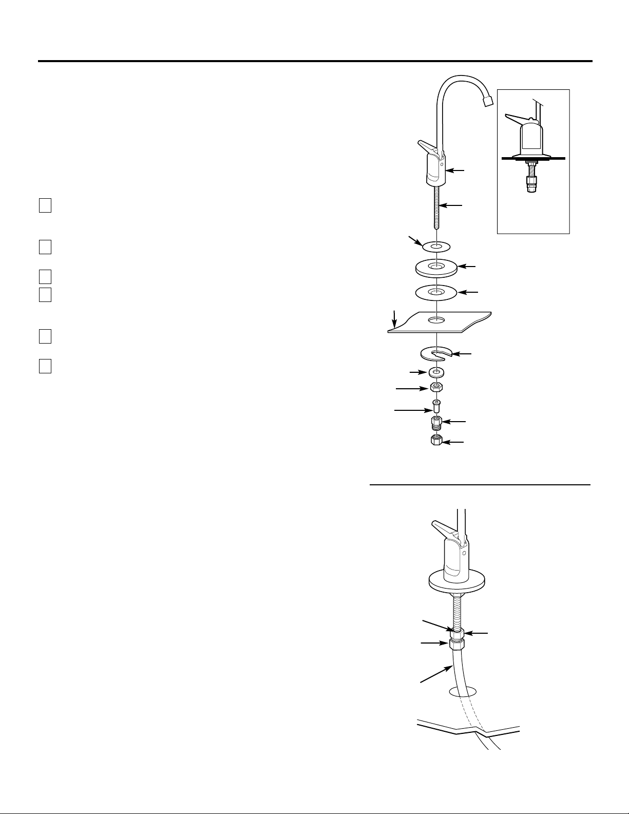
Step-by-step installation instructions.
Faucet Installation for Models GXST03C and GXSL03C (rev. 2)
Be sure there is room underneath the sink to make the needed connections.
Select one of the following places to install the faucet:
—IN an existing sink spray attachment or soap dispenser hole.
—IN a hole to be drilled in the sink top.
—IN a hole to be drilled in the countertop, next to the sink.
NOTE: Looking at second illustration at right, be sure the faucet base will fit
flat against the surface at the selected location so the gasket will seal.
If drilling is needed, make a 3⁄ 4 ″ dia. hole. Be sure to use the proper
procedure for drilling porcelain or stainless steel. Special drill bits may
be needed.
Place small gasket, base and large gasket (in that order) onto the faucet
stem. Next, place lock washer and hex nut onto faucet stud.
Insert washer into tubing adapter. Securely tighten to faucet stud.
Feed the length of 3 ⁄ 8 ″ OD tube from the bottom up through
the mounting hole. Connect to the tubing adapter as shown in second
illustration, tightening the compression nut securely.
Remove the short shipping tube and insert the spout into the faucet body.
Rotate spout into place.
Lower the faucet assembly into place on the underside of the mounting
hole. Place
the mounting bracket above the lock washer. While holding
the mounting bracket in place, securely tighten the hex nut.
6
5
4
3
2
1
3/8″ tubing, (run
to Filter II outlet)
Compression nut
Tubing adapter
Tubing
insert
Sink
Base
Lock washer
Faucet
Lever
Spout
Faucet
stud
Small gasket
Large gasket
Compression nut
Tubing adapter
Mounting bracket
Hex nut
Tubing
insert
ASSEMBLED
Page 8

8
Electronic Faucet Installation for Model GXSV10C
Be sure there is room underneath the sink to make the needed connections.
Select one of the following places to install the faucet:
—IN an existing sink spray attachment or soap dispenser hole.
—IN a hole to be drilled in the sink top.
—IN a hole to be drilled in the countertop, next to the sink.
NOTE: Looking at fourth illustration at right, be sure the faucet base will
fit flat against the surface at the selected location so the gasket will seal.
The base may have to be angled sideways or diagonally.
If drilling is needed, make a 1″–1 1⁄ 4 ″ dia. hole. Be
sure to use the
proper procedure for drilling porcelain or stainless steel. Special drill bits
may be needed.
Looking at first illustration, insert a screw into the NON-SLOTTED
base mounting hole. Turn a flat nut a few turns onto the screw.
Position the base gasket over the mounting hole. Set the base on the
gasket, routing the leadwire through the mounting hole. Holding the
flat nut under the sink with one finger, tighten the screw until just snug.
Turn the remaining flat nut a few turns onto the other screw. Position
the screw in the slotted base mounting hole and tighten until snug.
Make sure the gasket position is properly aligned and carefully tighten
both screws until the base is held firmly in place. Do not overtighten
and break the base.
Assemble the top faucet base and hex nut onto the faucet stud
(third illustration). Tighten the nut until snug.
Insert tubing insert into tubing adapter. Securely tighten to faucet stud.
Feed the length of 3/8″ OD tubing from the bottom up through the
faucet base. Connect to the tubing adapter as shown in fourth illustration,
tightening the compression nut securely.
Remove the short shipping tube and screw the spout into the faucet body.
Lower the faucet assembly and lock into place on the faucet base.
9
8
7
6
5
4
3
2
1
Faucet
base
Nut (2)
Screw (2)
1″–1 1/4″ dia.
mounting hole
in sink or
countertop
Gasket
Faucet base
TOP VIEW
Screw (2)
Nut (2)
Tubing insert
Hex nut
Top faucet base
Faucet
Lever
Spout
Faucet stud
ASSEMBLED
Step-by-step installation instructions.
Battery Pack Installation and Connection
In a dry location, within reach of the electronic base 3′ lead wire, select a
place for the battery pack (see illustration on page 5). The battery pack
attaches to most surfaces, using the included “sticky-back” Velcro
™
strip.
The battery pack uses two size AA batteries. Check to be sure they are
installed correctly. Then, remove the paper backing on the Velcro
™
strip
and secure the pack in place.
Fasten electronic base lead wire and battery pack connector together.
3
2
1
Base lead wire connector
(to battery pack)
3/8″ tubing, (run
to Filter 2 outlet)
Faucet base
Compression nut
Tubing insert
Tubing adapter
Compression nut
Tubing adapter
Page 9

9
Mounting Bracket to Cabinet Wall
The bracket can be used as a template for marking the location of the
mounting screws. When determining the
location of the bracket, make sure
you leave 1 1/2
″
to 2″of free area under the sumps to allow for sump removal
and enough space on either side to make the tubing connections.
Filter I
Filter II
Sump
Mounting
screws
Tubing
connector
(outlet)
Tubing
connector
(inlet)
Mounting
bracket
Sump
7 9⁄16″
1 1⁄2″ to 2″
Tubing Connections – Push-In Style
(Models GXSL03C [rev. 2] and GXSV10C)
Run the length of the 3⁄8 ″ tubing, connected to the bottom of the faucet,
to the filter system outlet (illustration above). Allow enough slack in the
tubing so that the unit can be easily removed.
Measure and cut the end of the tubing square using a sharp cutter or
knife. Remove any burrs (illustration A).
Inspect the end of the tubing, about 1 inch, to be sure there are no
imperfections. It may be necessary to cut the tubing again.
Mark the tubing for length of insertion. For 3/8″ OD tubing the insertion
length should be approximately 3/4 of an inch. Tubing must be fully
inserted to avoid leaks.
DO NOT REMOVE GRAY COLLET. Push the tubing all the way into the fitting
until it bottoms out. The insertion line should be hidden or barely visible
(illustration B and C). Slightly pull on the tubing to verify engagement.
Repeat the procedure to connect the tubing between the filter system
inlet and the water supply/saddle valve (illustration in the Installation
Overview section).
To remove tubing (illustration D), depress and hold gray collet.
Pull tubing to remove.
NOTE: Avoid installing the unit where the tubing is pulled at a sharp angle.
This type of installation may cause the fittings to leak. If using tubing other
than what is supplied, be sure it is high quality, exact size and roundness, and
has a smooth surface.
7
6
5
4
3
2
1
Engagement
3/4″ (3/8″ tubing)
Gray Collet
(DO NOT
REMOVE)
Gray Collet
Tubing
Cut tubing square
End of tubing round and smooth, with no cuts, nicks
or flat spots (approximately 1 inch)
Insertion line
Depress gray collet
and pull tubing
to remove.
A
B
C
D
Insert tubing
Insert
Gray Collet
(DO NOT REMOVE)
Insertion line
Tubing
Tubing must
be fully inserted
to avoid leaks.
3⁄4″
3
"
4
Page 10

10
About the water filtration system.
Filter Cartridge Installation or Replacement
CAUTION: Never remove the sumps when water pressure is in the Water
Filtration system.
Close the water supply/saddle valve to the filter. (See illustration in the
Installation Overview section for location of the water supply valve.)
Open the filtered water faucet.
Remove the sump, using the sump wrench tool provided, from the filter
head by rotating the sump as shown in the below illustration. Be careful,
the sump may be full of water. Be sure to keep the large o-ring seal.
If you are replacing a filter cartridge, remove and discard the used filter
cartridge.
Be sure the inside of the sump is clean. Thoroughly wash the inside of
the sump with hot, soapy water and rinse.
Remove the wrapper from the new filter cartridge and insert the filter
cartridge in the sump.
Some cartridges fit either way, while others fit only
one way. Observe markings on the cartridge.
NOTE: The Water Filtration system uses two different types of filter
cartridges. Be sure to install them correctly. Filter I
cartridge should always
be placed in the
Filter I
sump.
Filter II
cartridge should always be placed in
the
Filter II
sump.
See page 3 for a complete list of filter performance
characteristics.
5
4
3
2
1
Filter I
Filter II
O-ring seal
Cartridge
Sump II
Sump
Sump I
Label
TURN SUMP
TO INSTALL
TURN SUMP
TO REMOVE
Head
Bracket
Turn sump wrench tool
provided clockwise to
remove sump
OUTLET
INLET
Lightly lubricate the o-ring seal in the sump with clean food-grade
silicone grease (silicone grease is available through GE Parts and Services:
1-800-626-2002, Part Number: WS60X10005). Be sure it is fully seated in
its groove.
Hold the sump up to the filter head, aligning the center hole in the
cartridge with the protrusion on the bottom of the head. Failure to obtain
proper alignment may cause damage to the filter and/or filtration system,
which will degrade filter performance.
Being careful not to cross-thread, rotate the sump onto the filter head
and tighten securely by hand.
NOTE: If the sump will not tighten up to the head or if you feel resistance,
you may have the cartridge in upside down or misaligned. Take the
cartridge out and check for correct orientation or alignment and
reassemble.
Repeat steps 2 through 8 for the Filter II cartridge in the Filter II sump.
9
8
7
6
For Model GXSL03C (rev. 2)
FXSLC (rev. 2) Filter Set
(600-Gallon Capacity)
Filter I – White with no
end caps
Filter II – White with
yellow end caps
For Model GXSV10C
FXSVC (rev. 2) Filter Set
(600-Gallon Capacity)
Filter I – White with
green end caps
Filter II – Gray
Page 11

11
www.GEAppliances.com
Flush Procedure
Whenever water of unknown quality is passed through the GE Water Filtration
system, filter elements should be discarded and the filtration system flushed.
Circumstances that may require flushing the system are:
■ Boil-water advisory.
■ Flooding of the GE Water Filtration system.
■ Long-term non-use.
The procedure for flushing the GE Water Filtration system is:
See Filter Cartridge Replacement section and follow steps 1, 2, 3 and 4.
Next, reinstall the sumps (without the filter elements), turn water on and
flush water through the faucet for one minute.
Then, turn water off, remove sumps, empty water out of sumps and install
new filter elements.
Follow steps 5–11 in the Filter Cartridge Replacement section to complete.
4
3
2
1
Turn on the filtered water faucet. Then, slowly open the water
supply/saddle valve and allow the filter housing to fill.
Close the filtered water faucet. Then, check for leaks between the sump
and the head.
NOTE: If leaking, turn off the water supply and turn on the filtered
water
faucet. Disassemble the filter housing and check the o-ring for cuts, flat
spots, etc., and sealing surfaces for foreign material. Clean the o-ring and
lightly lubricate with clean silicone grease. Carefully press into the groove
in the sump. Reassemble and check for leaks.
If you are replacing the batteries, remove, properly discard and install
two new AA alkaline batteries in the battery pack. Removing the batteries
or momentarily disconnecting the lead wires resets the six-month
electronic timer. It is recommended that you change your batteries at
least once a year.
The filter cartridges contain activated carbon. When new, turn on the
filtered water faucet for ten minutes to flush the system.
Place filter change label on sump, inside cabinet door, or in another
convenient location. Write in date of filter change for future reference.
Filters should be changed every six months.
14
13
12
11
10
Page 12

12
Before you call for service…
Problem Possible Causes What To Do
Water contains tiny New filter cartridges contain • Turn on the filtered water faucet and allow these harmless
black particles activated carbon, which is a carbon particles to purge from the cartridge. Turn off the faucet
harmless black powder. when the water is clear.
Water has air bubbles Air in system after installation. • Will go away after water runs for a while.
and is cloudy
Indicator light on the Six months usage has occurred. • Replace both filter cartridges and batteries in the battery pack.
faucet base is flashing This is the maximum life of the
(GXSV10C only) filter cartridges.
Indicator light on the The faucet base lead wire • Connect.
faucet base is not working
is not connected to the battery
(GXSV10C only) pack lead wire.
Batteries may need to be • Observe orientation markings on the holder and install
replaced or they may have been correctly. Replace batteries if they are old.
installed incorrectly.
Lead wires damaged. • Inspect and repair as needed.
Chlorine taste and /or The filter cartridges are no •
Replace both filter cartridges.
odor in the product water longer removing chlorine
from the water supply.
Water dispenses Filter may have an integral • A slower flow (approx. 0.6 g/min.) is normal with this style of
very slowly
flow restrictor. filter. If flow rate is unacceptable, replace the filters with ones
that do not have integral flow restrictors.
The filters have been installed • A six-month change-out period is recommended.
for too long. Replace both filter cartridges.
The filter cartridges have • High sediment levels can cause premature clogging.
become clogged. Replace both filter cartridges.
Fittings are leaking Tubing may not be installed • Fully follow the installation instructions (page 9) and be sure
properly. the tubing is installed to the proper depth.
Tubing may be damaged. • Examine the end of tubing (approx. 1 inch) for defects such
as scratches, grooves, roundness, etc. Trim tubing and fully
reinstall.
Troubleshooting Tips
Save time and money! Review the chart below
first and you may not need to call for service.
Page 13

13
Parts List.
www.GEAppliances.com
*NOTE: Codes in the state of Massachusetts
require installation by a licensed plumber
and do not permit the use of the saddle
valve. For installation, use plumbing code
248-CMR of the Commonwealth of
Massachusetts.
Electronic
Monitor
Faucet for
Model
GXSV10C
Nonmonitored
Faucet for
Models
GXSL03C (rev. 2)
General Electric parts catalog.
REF. NO. PART NO. PART DESCRIPTION
0001 WS02X10001 SCREW, #10-14 X 3/4″ 88
0002 WS28X10010 MOUNTING BRACKET 1 1
0005 WS02X10003 SCREW, #10-14 X 1 1/4″ 22
0006 WS22X10002 ELBOW, 3/8″ NPT X 3/8″ (compression) – –
0006 WS22X10032 ELBOW, 3/8″ NPT X 3/8″ (push-in) 2 2
0007 WS19X10011 HEAD 2 2
0008 WS03X10001 O-RING, 3 3/8″ X 3 5/8″ 22
0009 WS30X10002 SUMP 2 2
0010 WS22X10003 NIPPLE, 3/8″ NPT X 1 1/2″ 11
0012 WS07X10008 TUBING, 3/8″ X 20 FT–WH 1 1
0015 WS03X10044 TUBING ADAPTER ASM. 2 2
0017 WS15X10008 SADDLE VALVE/SUPPLY 1 1
0018 WS15X10002 FAUCET ASM. (monitored) – 1
WS15X10022 FAUCET ASM. (nonmonitored) 1 –
0019 WS10X10008 TOP FAUCET BASE BLACK – 1
0020 WS02X10007 SCREW, #6-32 X 1 3/8″ –2
0021 WS10X10002 BASE FAUCET KIT – 1
0022 WS02X10008 NUT – 2
0023 WS08X10003 GASKET FAUCET – 1
0024 WS06X10001 HOLDER BATTERY – 1
0025 FXSLC (rev. 2) FILTER SET – LEAD/CYST 1 –
FXSVC (rev. 2) FILTER SET – VOC – 1
0200 WX5X140 WRENCH SUMP 1 1
0999 49-50039 PM MANUAL USE & CARE/
INSTALLATION 1 1
G
X
S
L
0G
3X
CS
RV
E1
V0
2C
00
11
To obtain replacement parts, call toll-free
800.626.2002 (US), 800.663.6060 (CanadaEnglish), 800.361.3869 (Canada-French)
Saddle Valve
*
Page 14

14
Notes.
Page 15

15
Notes.
Page 16

16
Printed in the United States
Consumer Support.
GE Appliances Website
www.GEAppliances.com
Have a question or need assistance with your appliance? Try the GE Appliances Website 24 hours a day, any day of the year! For
greater convenience and faster service, you can now download Owner’s Manuals, order parts, catalogs, or even schedule service
on-line. You can also “Ask Our Team of Experts™” your questions, and so much more
...
Schedule Service www.GEAppliances.com
Expert GE repair service is only one step away from your door. Get on-line and schedule your service at your convenience 24
hours any day of the year! Or call 800.GE.CARES (800.432.2737) during normal business hours.
Real Life Design Studio www.GEAppliances.com
GE supports the Universal Design concept—products, services and environments that can be used by people of all ages, sizes
and capabilities. We recognize the need to design for a wide range of physical and mental abilities and impairments. For details
of GE’s Universal Design applications, including kitchen design ideas for people with disabilities, check out our Website today.
For the hearing impaired, please call 800.TDD.GEAC (800.833.4322).
Extended Warranties www.GEAppliances.com
Purchase a GE extended warranty and learn about special discounts that are available while your warranty is still in effect. You
can purchase it on-line anytime, or call 800.626.2224 during normal business hours. GE Consumer Home Services will still be
there after your warranty expires.
Parts and Accessories www.GEAppliances.com
Individuals qualified to service their own appliances can have parts or accessories sent directly to their homes (VISA,
MasterCard and Discover cards are accepted). Order on-line today, 24 hours every day or by phone at 800.626.2002 during
normal business hours.
Instructions contained in this manual cover procedures to be performed by any user. Other servicing generally should be referred to
qualified service personnel. Caution must be exercised, since improper servicing may cause unsafe operation.
Contact Us www.GEAppliances.com
If you are not satisfied with the service you receive from GE, contact us on our Website with all the details including your phone
number, or write to: General Manager, Customer Relations
GE Appliances, Appliance Park
Louisville, KY 40225
Register Your Appliance www.GEAppliances.com
Register your new appliance on-line—at your convenience! Timely product registration will allow for enhanced communication
and prompt service under the terms of your warranty, should the need arise. You may also mail in the preprinted registration
card included in the packing material.
LIMITED ONE-YEAR WARRANTY
• What does this warranty cover?
— Any defect in materials or workmanship in the manufactured product.
• What does this warranty not cover?
— Filter Cartridges.
— Service trips to your home to teach you how to use the product.
— Improper installation.
— Failure of the product if it is abused, misused, altered or used for other
than the intended purpose.
— Defects that result from improper installation or damage not caused
by GE.
— Liability on the part of GE under this or any other warranty for any
indirect or consequential damage.
— Products that are used for commercial or industrial applications.
— Use of this product where water is microbiologically unsafe or of
unknown quality, without adequate disinfection before or after the
system. Systems certified for cyst reduction may be used on disinfected
water that may contain filterable cysts.
— Damage to the product caused by accident, fire, floods or acts of God.
— Incidental or consequential damage caused by possible defects with this
appliance, its installation or repair.
• For how long after the original purchase?
— One year.
• How do I make a warranty claim?
— Return to the retailer from which it was purchased, along with a copy
of the “Proof of Purchase.” This warranty excludes the cost of shipping
or service calls to your home.
• How does state law relate to this warranty?
— This warranty gives you specific legal rights, and you may also have
other rights which vary from state to state. THIS WARRANTY IS
INTENDED TO BE IN LIEU OF ALL OTHER WARRANTIES,
WHETHER EXPRESS OR IMPLIED, INCLUDING THE
WARRANTIES OF MERCHANTABILITY AND FITNESS FOR A
PARTICULAR PURPOSE.
Contact us at www.GEAppliances.com, or call 800.GE.CARES (800.432.2737) in the
U.S., or toll-free 866.777.7627 in Canada.
GE Water Filtration System Warranty.
Page 17

17
Information de sécurité . . . . . . . . .18
Instructions d’utilisation . . . . .19, 20
Spécifications . . . . . . . . . . . . . . . . . . . . . . . . .19
Utilisation du système . . . . . . . . . . . . . . . . . .20
Instructions d’installation . . . .21–27
Cartouches de filtration–
installation ou remplacement . . . . . . . . . .26, 27
Étapes de l’installation . . . . . . . . . . . . . .23–25
Installation du porte-pile . . . . . . . . . . . . . . . . .24
Installation du robinet . . . . . . . . . . . . . . .23, 24
Montage mural . . . . . . . . . . . . . . . . . . . . . . . .25
Outillage/matériel nécessaire . . . . . . . . . . . .21
Processus de rinçage . . . . . . . . . . . . . . . . . . .27
Raccordement des tubes . . . . . . . . . . . . . . . . .25
Recommandations importantes . . . . . . . . . . . .21
Source d’alimentation du filtre . . . . . . . . . . . .22
Avant de contacter un dépanneur
Conseils pour le diagnostic . . . . . . . . . . . . . . .28
Service-client
Garantie . . . . . . . . . . . . . . . . . . . . . . . . . . . . .32
Liste des pièces/catalogue . . . . . . . . . . . . . . .29
Service à la clientèle . . . . . . . . . . . . . . . . . . .32
Le produit GXSL03C (rév. 2) a été
testé et homologué par NSF
International, selon la norme
ANSI/NSF no42 pour la réduction
de la concentration de particules
(classe I), la réduction de la
concentration de chlore et la
suppression des goûts et odeurs,
et selon la norme no53 pour la
réduction de la turbidité et des
concentrations de plomb, mercure,
spores, amiante, atrazine et Lindane.
Le produit GXSV10C a été testé et
homologué par NSF International,
selon la norme ANSI/NSF n
o
42 pour
la réduction de la concentration de
particules (classe I), la réduction
de la concentration de chlore et la
suppression des goûts et odeurs,
et selon la norme no53 pour la
réduction de la turbidité et des
concentrations de plomb, mercure,
spores, amiante et composés
organiques volatiles.
Écrivez ici le numéro de modèle
et le numéro de série :
Modèle # ____________________
Série # ______________________
Vous trouverez ces numéros sur
la bride du corps de filtre.
Page 18

CONSERVER CES INSTRUCTIONS
LIRE ATTENTIVEMENT ET RESPECTER CES PRESCRIPTIONS DE SÉCURITÉ.
■
Installer ou remiser le produit à un emplacement qui n’est pas
exposé au gel ou aux intempéries. Le gel de l’eau fera subir
des détériorations au produit. Ne pas tenter de traiter une
eau dont la température est supérieure à 100°F.
AVERTISSEMENT : Éliminer après
l’installation tous les matériaux d’emballage et matériaux
non utilisés; les petites pièces qui ne sont pas utilisées
pourraient susciter un danger d’étouffement pour un
enfant.
■
Le système de filtration d’eau peut résister à une pression
maximale de 125 lb/po2. Si la pression de distribution locale
est supérieure à 100 lb/po2, installer un robinet de réduction
de pression en amont du système de filtration d’eau.
INFORMATION DE SÉCURITÉ IMPORTANTE.
LIRE LA TOTALITÉ DES INSTRUCTIONS AVANT D’UTILISER LE PRODUIT.
Observer toutes les instructions présentées dans ce manuel pour assurer la
sécurité et minimiser les risques de dommages matériels ou corporels.
MESURES DE SÉCURITÉ
■ Consulter le service local des travaux publics au sujet des
codes de plomberie. L’installation du système de filtration
d’eau doit être conforme aux prescriptions du code de
plomberie local.
■ Utiliser le système de filtration d’eau uniquement sur une
canalisation d’eau potable FROIDE. Les cartouches de filtration
ne purifient pas l’eau et ne peuvent rendre potable une eau
qui ne l’est pas.
■ Ne pas utiliser ce produit sur une canalisation d’eau chaude
(100°F maximum).
AVERTISSEMENT : Ne pas utiliser ce
produit avec de l’eau microbiologiquement polluée ou
de qualité inconnue sans avoir installé un dispositif de
désinfection approprié avant ou après le système. Les
systèmes homologués pour la retenue des spores peuvent
être utilisés pour la filtration d’une eau désinfectée qui
peut contenir des spores filtrables.
INSTALLATION
Avant toute utilisation, on doit installer le système de filtration d’eau soit à un emplacement adéquat conformément aux
instructions d’installation.
18
AVERTISSEMENT!
Page 19

19
Spécifications. www.GEAppliances.com
Des cartouches de filtration au charbon actif permettent d’éliminer de l’eau
des composés responsables de goûts ou odeurs désagréables. On utilise
fréquemment ces filtres pour éliminer les goûts et odeurs imputables au
chlore. Les filtres permettent également de réduire la concentration d’autres
éléments indésirables dans l’eau de consommation, comme composés
organiques et plomb.
NOTE : Les filtres pour goûts et odeurs peuvent supprimer pendant quelque
temps de petites quantités de sulfure d’hydrogène (responsable d’une odeur
caractéristique d’oeufs pourris), mais le charbon actif s’épuise rapidement.
Pour l’élimination en permanence du sulfure d’hydrogène, on doit utiliser
un autre équipement de conditionnement de l’eau.
Pour modèle GXSL03C (rév. 2)
Filtre FXSLC (rév. 2)
(capacité 600 gallons)
Filtre I–Blanc, sans
embouts
Filtre II–Blanc, avec
embouts jaunes
• Réduction de
souillures, rouille et
sédiments
• Réduction des goûts
et odeurs désagréables
• Réduction du chlore :
goûts et odeurs
• Réduction du
plomb
• Réduction de
l’amiante
• Réduction de mercure
• Réduction de
l’atrazine
• Réduction des spores
filtrables, comme
cryptosporidium et
giardia
• Réduction du Lindane
(pesticide)
• Réduction nominale
des particules de
0,5–1 micron
Pour modèle GXSV10C
Filtre FXSVC (rév. 2)
(capacité 600 gallons)
Filtre I–Blanc, avec
embouts verts
Filtre II–Gris
• Réduction de
souillures, rouille et
sédiments
• Réduction des goûts
et odeurs désagréables
• Réduction du chlore :
goûts et odeurs
• Réduction du
plomb
• Réduction de
l’amiante
• Réduction de mercure
• Réduction des spores
filtrables, comme
cryptosporidium et
giardia
• Réduction des
composés organiques
volatiles COV
• Réduction nominale
des particules de
0,5–1 micron
Pression d’arrivée d’eau (mini-maxi) – 40–125 livres par pouce carré
Température de l’eau traitée (mini-maxi) – 40°–100 °F
Raccords entrée-sortie – 3/8 po NPT (raccords de connexion et tube inclus)
Débit nominal – 0,6 gallon par minute (GXSL03C [rév. 2])
0,6 gallon par minute (GXSV10C)
On peut personnaliser un système de filtration d’eau au moyen de toute combinaison
des cartouches de filtration mentionnées ci-dessus, selon le traitement nécessaire pour
une eau particulière.
Le système de filtration de l’eau met en œuvre deux cartouches de filtration.
Ce système se conforme aux normes ANSI/NSF 42 et 53 pour les demandes
spécifiques de rendement telles que vérifiées et obtenues par des données
d’essais.
Page 20

Description sommaire du système de filtration d’eau.
Utilisation du système de filtration, et description des cartouches
de filtration
Le robinet installé sur le plan de travail d’une cuisine permet de puiser
de l’eau de consommation filtrée. Il comporte une manette à manoeuvre
manuelle chargée par ressort, qui permet la fermeture automatique. Pour
maintenir le robinet ouvert, pousser la manette vers le haut pour la mettre
en appui contre le col de cygne.
Longévité de la cartouche de filtration – La longévité en service de la cartouche
de filtration dépend de divers paramètres, comme les suivants :
Volume de consommation d’eau.
Quantité dans l’eau de sédiments, composés responsables de goûts et/ou odeurs,
plomb et autres substances indésirables.
Quel que soit le système de filtration utilisé, on doit remplacer les cartouches
de filtration à intervalles de six mois, lorsque l’illumination du témoin
électronique sur la base indique que ceci est nécessaire. Si l’eau traitée est
de très médiocre qualité, on peut observer la réapparition de substances
indésirables dans l’eau avant l’expiration d’une période de six mois. Dans
ce cas on doit immédiatement remplacer les cartouches de filtration. Si le
système est utilisé également pour l’élimination du plomb et de contaminants
chimiques, il est PLUS IMPORTANT de remplacer les cartouches à intervalles
de six mois ou moins.
NOTE : Si l’eau traitée contient une quantité élevée de sédiments les filtres à
charbon peuvent s’obstruer prématurément, ce qui réduit le débit d’eau
filtrée au niveau du robinet de puisage. On doit remplacer les cartouches pour
rétablir le débit usuel.
Témoin électronique (GXSV10C seulement) – Le témoin lumineux situé sur
la base du robinet est associé à un circuit électronique comportant une
minuterie (mesure d’une période de six mois); le témoin s’illumine pour
indiquer qu’il est temps de remplacer les cartouches de filtration. Lors de
l’installation initiale des piles, le témoin s’illumine brièvement pour indiquer
que les circuits électroniques sont opérationnels; s’il ne s’illumine pas, c’est
probablement parce que les piles sont installées à l’envers, ou parce que des
fils ne sont pas connectés.
Après environ six mois de service, le témoin lumineux commence à clignoter;
il est temps de remplacer les cartouches de filtration. Lors du remplacement
des cartouches de filtration, remplacer également les piles. On doit utiliser
deux piles AA.
2
1
Robinet d’eau filtrée
Ouverture
Témoin lumineux
Ouverture
permanente
20
Page 21

21
Illustration de l’installation
Instructions d’installation.
Recommandations importantes concernant l’installation
■ Consulter le service local des travaux publics au sujet des
codes de plomberie. L’installation du système de filtration
d’eau doit être conforme aux prescriptions du code de
plomberie local.
■ Utiliser le système de filtration d’eau uniquement sur une
canalisation d’eau potable FROIDE. Les cartouches de filtration
ne purifient pas l’eau et ne peuvent rendre potable une eau qui
ne l’est pas. NE PAS utiliser ce produit sur une canalisation
d’eau CHAUDE (100OF maximum).
■ Protéger le système de filtration d’eau et la tuyauterie contre
le gel. La congélation d’eau dans le système lui fera subir des
dommages.
■ Le système de filtration d’eau peut résister à une pression
maximale de 125 lb/po2. Si la pression de distribution locale est
supérieure à 100 lb/po2durant la journée (elle peut atteindre un
niveau plus élevé la nuit), installer un robinet de réduction de
pression en amont du système de filtration d’eau.
AVERTISSEMENT : Ne pas utiliser ce
produit avec de l’eau microbiologiquement polluée ou
de qualité inconnue sans avoir installé un dispositif de
désinfection approprié avant ou après le système. Les
systèmes GXSL03C (rév. 2) et GXSV10C sont homologués
pour la rétention des spores; on peut les utiliser pour la
désinfection d’une eau qui peut contenir des spores
filtrables. Tester périodiquement l’eau filtrée pour vérifier
que la performance du système demeure satisfaisante.
Éliminer en sécurité les petites pièces qui peuvent rester
inutilisées après l’installation; elles peuvent susciter un
danger d’étouffement pour les jeunes enfants.
■ Tournevis Phillips et à lame plate
■ Pince et clé à molette
■ Perceuse électrique ou à piles, et foret de 1/4 po (pour
l’installation du robinet de prise en charge)
■ Perceuse électrique et foret pour trou de 1 po–1 1/4 po
(selon le besoin), si un trou de montage est nécessaire
pour l’installation du robinet
MISE EN GARDE : Pour éviter
d’endommager l’évier, consulter un installateur ou
plombier qualifié au sujet de la méthode de perçage;
l’emploi d’un foret spécial peut être nécessaire pour le
perçage sur acier inoxydable ou matériau émaillé.
Articles fournis avec le produit :
■ Système de filtration d’eau, avec bride de montage et vis
■ Brochures descriptives du produit (manuel de l’utilisateur,
instructions d’installation, fiche technique du produit, carte
d’enregistrement du produit)
■ Robinet de prise en charge
■ Robinet de puisage de l’eau filtrée–montage sur évier ou
plan de travail
■ Base du robinet avec témoin lumineux électronique et piles
(GXSV10C seulement)
■ Tube de 3/8 po et raccords, pour les raccordements
■ Clé pour corps de filtre
Robinet de
puisage de l’eau
filtrée
Piles
Eau
chaude
Robinet d’arrêt
NOTE : Pour changer les cartouches
de filtration, on doit fermer l’arrivée
d’eau. Il est pratique d’avoir un
robinet d’arrêt à proximité. Un robinet
d’arrêt est fréquemment installé sur
la canalisation d’alimentation du
robinet principal de l’évier.
Eau
froide
Robinet
d’alimentation
du filtre
Douille inerne pour tube
Raccord d’adaptation pour tube
Écrou de compression
Entrée de l’eau
Sortie de l’eau
Tube
Vis de
montage (2)
Filtre I
Filtre II
Tube
Installer le système de
filtration d’eau sur la
canalisation d’eau froide,
sous l’évier de cuisine
et/ou salle de bains, pour
filtrer l’eau de
consommation froide.
Outillage et matériel nécessaires pour l’installation
Évier
Lire la totalité du manuel. Le non-respect de certaines instructions ou règles pourrait susciter des dommages
matériels ou corporels.
Page 22

22
B. AUTRE OPTION POUR INSTALLATION RÉSIDENTIELLE–
Lorsque le code local le permet
*Utilisation uniquement sur une canalisation métallique de dia. ext.
1/2 po ou plus
NOTE : Dans l’État du Massachusetts, les codes en vigueur exigent que cet équipement soit
installé par un plombier licencié, et que le raccordement à la canalisation d’alimentation ne
soit pas effectué par un robinet de prise en charge. Avant l’installation, consulter le code de
plomberie 248-CMR du Commonwealth of Massachusetts.
Fermer l’arrivée d’eau froide; installer le robinet de prise en charge selon les
indications de l’illustration à droite.
DANGER : À titre de protection contre un choc électrique mortel ou de
graves blessures, utiliser uniquement une perceuse à piles pour percer le trou.
NE PAS UTILISER UNE PERCEUSE ÉLECTRIQUE.
Fermer le robinet de prise en charge–rotation de la manette dans le sens
horaire.
Ouvrir le robinet d’arrêt et plusieurs robinets dans la maison pour permettre
l’évacuation de l’air du système. Fermer les robinets lorsque l’eau s’écoule
sans turbulence.
3
2
1
Autre configuration de raccordement
(avec robinet de prise en charge)*
Prépercer
un trou de
1/4 po
Joint – veiller à ce que le
joint reste en place
Bride X
Écrous (2) – pas
nécessaires
si les trous
de la bride
sont filetés
Robinet d’arrêt
Manette
Raccord
d’adaptation
pour tube
Douille
inerne
pour tube
Bride Z
Utiliser ces pièces pour le
raccordement du tube
*Utilisation uniquement sur
une canalisation métallique
de dia. ext. 1/2 po ou plus
Instructions d’installation.
Source d’alimentation du filtre
Consulter et respecter le code de plomberie local lors de la planification et de l’installation
de la canalisation d’alimentation du filtre en eau froide. Pour l’installation dans une
résidence neuve avec des raccords de plomberie standard, voir les deux premières
illustrations ci-dessous. La troisième illustration ci-dessous décrit une installation typique
dans une résidence existante, avec robinet de prise en charge.
A. CONFIGURATION D’INSTALLATION PRÉFÉRENTIELLE
Fermer l’arrivée d’eau froide.
Respecter les prescriptions du code de plomberie; installer un raccord sur la
canalisation d’eau froide pour le raccordement du tube de diamètre extérieur 3/8 po.
Un raccordement typique est illustré à droite (pièces non fournies). Ne pas oublier
d’utiliser un robinet d’arrêt.
2
1
Écrou de
compression
Configuration préférentielle
de raccordement
(avec raccord à compression)
Douille inerne (non fournie)
Canalisation
d’eau froide
Tube 3/8 po, vers
l’entrée du filtre
Virole
Robinet d’arrêt
Emplacement typique
Canalisation
d’eau froide
Installer le robinet
sur la bride. NE PAS
TROP SERRER.
Joint de
caoutchouc
Une partie du filetage
devrait être visible
Page 23

23
Étapes de l’installation.
Installation du robinet–modèles GXST03C et GXSL03C (rév. 2)
Vérifier qu’il y a suffisamment d’espace sous l’évier pour les raccordements.
Choisir l’un des emplacements suivants pour l’installation du robinet.
—Trou existant pour douchette d’évier ou distributeur de savon.
—Trou à percer dans le rebord de l’évier.
—Trou à percer dans le plan de travail, près de l’évier.
NOTE : Consulter la seconde illustration à droite; vérifier que la base du
robinet d’arrêt reposera à plat contre la surface d’appui à l’emplacement
choisi, pour que les joints assurent une bonne étanchéité.
Si une opération de perçage est nécessaire, percer un trou de 3/4 po.
Veiller à employer la méthode convenable pour le perçage dans l’acier
inoxydable ou l’émail. Il peut être nécessaire d’utiliser un foret spécial.
Enfiler les pièces suivantes sur la tige tubulaire du robinet, dans l’ordre
indiqué : petit joint, base et grand joint. Placer ensuite la rondelle-frein
et l’écrou hexagonal sur la tige tubulaire du robinet.
Insérer le joint dans le raccord d’adaptation du tube. Bien serrer sur
la tige du robinet.
Par le dessous et à travers le trou de montage, faire passer la section
de tube de dia. ext. 3/8 po. Installer l’adaptateur (voir la seconde
illustration), bien serrer l’écrou de compression.
Enlever le tube d’emballage court; insérer le col de cygne dans le corps
du robinet. Faire pivoter le col de cygne pour le mettre en place.
Mettre le robinet en place. Par le dessous du trou de montage, placer
la bride de montage au-dessus de la rondelle-frein. Tout en immobilisant
la bride de montage, bien serrer l’écrou hexagonal.
6
5
4
3
2
1
Évier
Base
Rondellefrein
Robinet
Manette
Col de
cygne
Tige
tubulaire
du robinet
Petit joint
Grand joint
Écrou de compression
Raccord
d’adaptation
pour tube
Bride de montage
Écrou
hexagonal
Douille inerne
pour tube
Tube 3/8 po (pour
raccordement à la
sortie du filtre II)
Écrou de
compression
ROBINET ASSEMBLÉ
Raccord d’adaptation
pour tube
Douille
inerne
pour tube
Page 24

24
Installation du robinet à témoin électronique–modèle GXSV10C
Vérifier qu’il y a suffisamment d’espace sous l’évier pour les raccordements.
Choisir l’un des emplacements suivants pour l’installation du robinet.
—Trou existant pour douchette d’évier ou distributeur de savon.
—Trou à percer dans le rebord de l’évier.
—Trou à percer dans le plan de travail, près de l’évier.
NOTE : Consulter la quatrième illustration à droite; vérifier que la base du
robinet d’arrêt reposera à plat contre la surface d’appui à l’emplacement
choisi, pour que les joints assurent une bonne étanchéité. Il pourrait être
nécessaire d’orienter la base latéralement ou en diagonale.
Si une opération de perçage est nécessaire, percer un trou de 1 po–
1 1⁄ 4 po. Veiller à employer la méthode convenable pour le perçage dans
l’acier inoxydable ou l’émail. Il peut être nécessaire d’utiliser un foret spécial.
Consulter la première illustration; insérer une vis dans le trou de
montage SANS RAINURE de la base. Visser de quelques tours un écrou
plat sur la vis.
Positionner le joint de la base sur le trou de montage. Placer la base sur
le joint; faire passer les conducteurs à travers le trou de montage.
Maintenir l’écrou plat sous l’évier avec un doigt et serrer la vis pour
établir le contact.
Faire tourner l’écrou plat restant de quelques tours sur l’autre vis.
Positionner la vis dans le trou de montage avec rainure de la base;
serrer pour établir le contact. Vérifier que le joint est convenablement
aligné et serrer prudemment les deux vis jusqu’à ce que la base soit
fermement maintenue en place. Ne pas serrer excessivement pour ne
pas briser la base.
Assembler la base supérieure du robinet et l’écrou hexagonal sur la tige
du robinet (troisième illustration). Serrer l’écrou pour établir le contact.
Insérer la douille inerne pour tube dans le raccord d’adaptation du tube.
Bien serrer sur la tige du robinet.
Par le dessous et à travers la base du robinet, faire passer la section
de tube de dia. ext. 3/8 po. Installer l’adaptateur (voir la quatrième
illustration); bien serrer l’écrou de compression.
Enlever le tube d’emballage court; visser le col de cygne dans le corps
du robinet.
Mettre le robinet en place. Bloquer le robinet sur la base.
9
8
7
6
5
4
3
2
1
Base du
robinet
Écrous (2)
Vis (2)
Trou de montage 1 po–
1 1/4 po, dans l’évier
ou le plan de travail
Joint
Base du
robinet
VUE DU DESSUS
Vis (2)
Écrous (2)
Conducteurs de
raccordement aux piles
Tube 3/8 po (pour
raccordement à la
sortie du filtre II)
Base du
robinet
Écrou de compression
Douille inerne pour tube
Écrou hexagonal
Base (section supérieure)
Robinet
Manette
Col de
cygne
Tige tubulaire
du robinet
Écrou de
compression
Raccord d’adaptation
pour tube
ROBINET ASSEMBLÉ
Étapes de l’installation.
Installation et raccordement des piles
En un endroit sec accessible aux conducteurs de 3 pi de la base
électronique, choisir un emplacement d’installation des piles (voir
l’illustration de la page 21). On peut fixer les piles sur la plupart des
surfaces à l’aide d’un morceau de VelcroMC.
Le porte-pile comporte deux piles AA. Vérifier que les piles sont
correctement installées. Enlever ensuite l’endos de papier de la section
de VelcroMCpour fixer le porte-pile en place.
Connecter ensemble le connecteur du porte-pile et les conducteurs de
la base électronique.
3
2
1
Douille inerne pour tube
Raccord d’adaptation
pour tube
Page 25

25
Fixation de la bride de montage sur la paroi du placard
On peut utiliser la bride de montage comme un gabarit pour marquer
l’emplacement des vis de fixation. Lors du choix de l’emplacement de fixation
de la bride de montage, veiller à disposer d’un espace libre de 1 1/2 po à 2 po
au-dessous des corps de filtre pour permettre leur démontage, et d’un espace
suffisant sur les deux côtés pour le raccordement des tubes.
Filtre I
Filtre II
Corps de
filtre
Vis de
montage
Raccord
de sortie
Raccord
d’entrée
Bride du
montage
Corps de
filtre
7 9⁄16 po
1 1/2 po à
2 po
Raccordement des tubes par enfoncement
(modèles GXSL03C (rév. 2) et GXSV10C)
Installer une section de tube de 3/8 po entre le robinet et la sortie du
système de filtration (voir l’illustration ci-dessus). Utiliser une section de
tube suffisamment longue pour qu’il soit facile de démonter l’ensemble.
Mesurer, et couper l’extrémité du tube à l’équerre avec un couteau
acéré ou un autre instrument. Éliminer les bavures (illustration A).
Inspecter l’extrémité du tube; il faut que sur une distance de 1 po il n’y ait
pas d’imperfection. Il peut être nécessaire de couper le tube de nouveau.
Marquer la limite d’insertion sur le tube. Pour un tube de diamètre
externe 3/8 po, la distance d’insertion est d’environ 3/4 po. Le tube doit
être completement inséré pour éviter les fuites.
NE PAS ENLEVER LA VIROLE GRISE. Enfoncer complètement le tube dans
le raccord, jusqu’à la position de butée. La limite d’insertion devrait être
cachée ou à peine visible (illustration B et C). Tirer légèrement sur le tube
pour vérifier l’engagement.
Répéter les étapes précédentes pour installer une section de tube entre
l’entrée du système de filtration et le robinet de prise en charge ou le
point d’arrivée d’eau (voir l’illustration à la section Illustration de
l’installation).
Pour enlever le tube (illustration D), enfoncer et maintenir la virole grise.
Tirer sur le tube pour l’extraire.
NOTE : Éviter une configuration d’installation dans laquelle le tube devrait
former un angle. Ce type d’installation pourrait produire des fuites au niveau
des raccords. Dans le cas de l’utilisation de tube flexible autre que celui qui
est fourni, veiller à ce qu’il s’agisse d’un produit de grande qualité, à surface
lisse, parfaitement rond et de même taille.
7
6
5
4
3
2
1
Zone
d’engagement
3/4 po (pour tube
de 3/8 po)
Virole grise
(NE PAS
ENLEVER)
Virole grise
Tube
Couper à l’équerre
Extrémité du tube ronde et lisse, sans coupure,
déformation ou zone plate (environ 1 po)
Canalisation
à insérer
3/4 po
A
C
D
Enfoncer la virole grise
et tirer sur le tube
pour l’extraire.
Insérer le tube
B
Insérer
Virole grise
(NE PAS ENLEVER)
Canalisation
à insérer
Tube
Le tube doit être
completement inséré
pour éviter les fuites.
3⁄4po
3
"
4
Page 26

26
Utilisation du système de filtration de l’eau.
Cartouches de filtration – Installation ou remplacement
MISE EN GARDE : Ne jamais enlever les corps de filtre lorsque le système
de filtration est pressurisé.
Fermer le robinet d’arrêt de la canalisation qui alimente le filtre.
(Pour l’emplacement de ce robinet, voir l’illustration à la section
Illustration de l’installation). Ouvrir le robinet de puisage de l’eau filtrée.
Pour enlever le filtre, faire tourner le corps de filtre selon les indications
de l’illustration, avec l’outil fourni. Travailler prudemment–le corps de
filtre peut être plein d’eau. Veiller à conserver le grand joint torique.
Pour le remplacement de la cartouche de filtration, enlever et jeter la
cartouche usée.
Vérifier la propreté de l’intérieur du corps de filtre. Laver parfaitement
l’intérieur du corps de filtre avec de l’eau chaude savonneuse, puis rincer.
Retirer la cartouche de filtration neuve de son emballage; insérer la
cartouche dans le corps de filtre. Il peut être nécessaire de respecter
une orientation particulière; ceci est alors indiqué par des marques
apposées sur la cartouche.
NOTE : Diverses cartouches de filtration sont utilisables avec le système de
filtration d’eau. Veiller à installer chaque type de cartouche correctement.
Veiller à toujours placer la cartouche de Filtration I dans le corps de Filtre I,
et à placer la cartouche de Filtration II dans le corps de Filtre II. Pour les
caractéristiques de performance des filtres, voir la page 19.
5
4
3
2
1
Filtre I
Filtre II
Joint
torique
Cartouche
de filtration
Corps de
filtre II
Corps de filtre
Corps de filtre I
Étiquette
FAIRE
TOURNER
LE CORPS
DE FILTRE
POUR
INSTALLER
FAIRE TOURNER
POUR DÉVISSER
Tête de
filtre
Bride de
montage
Faire tourner l’outil dans
le sens horaire pour
dévisser le corps de filtre
RACCORD
DE SORTIE
RACCORD
D’ENTRÉE
Lubrifier légèrement le joint torique avec une graisse aux silicones de
qualité alimentaire (graisse aux silicones disponible auprès de GE –
Pièces et services au : 1-800-626-2002 Numéro de pièce : W560X10005.
Veiller à ce que le joint soit bien placé dans la rainure.
Tenir le corps de filtre sous la tête de montage; aligner le trou central de
la cartouche avec la pièce en saillie sous la tête. Un défaut d’alignement
pourrait faire subir des dommages au filtre et/ou au système de filtration,
ce qui en dégraderait la performance.
Visser le corps de filtre sur la tête de montage–veiller à ne pas détériorer
le filetage; bien serrer à la main.
NOTE : Si on perçoit une résistance ou si le corps de filtre ne se visse
pas bien, c’est peut-être parce que la cartouche de filtration n’est pas
correctement alignée, ou est incorrectement orientée. Retirer la
cartouche et veiller à l’orienter correctement avant de visser le corps
de filtre.
Répéter les étapes 2 à 8 pour installer la cartouche de Filtration II dans le
corps de Filtre II.
9
8
7
6
Pour modèle GXSL03C (rév. 2)
Filtre FXSLC (rév. 2)
(capacité 600 gallons)
Filtre I – Blanc, sans
embouts
Filtre II – Blanc, avec
embouts jaunes
Pour modèle GXSV10C
Filtre FXSVC (rév. 2)
(capacité 600 gallons)
Filtre I – Blanc, avec
embouts verts
Filtre II – Gris
Page 27

27
www.GEAppliances.com
Processus de rinçage
Chaque fois que le système de filtration GE est exposé à de l’eau de qualité
inconnue, on devrait jeter les éléments de filtration et rincer le circuit.
Circonstances qui peuvent nécessiter un rinçage du circuit :
■ Notification de la nécessité de faire bouillir l’eau.
■ Inondation du système de filtration d’eau GE.
■ Inutilisation prolongée.
Méthode de rinçage du système de filtration GE :
Voir la section Cartouches de filtration–Installation ou remplacement; exécuter
les étapes 1, 2, 3 et 4.
Réinstaller les corps de filtre (sans les éléments de filtration), faire circuler
l’eau et laisser l’eau s’écouler par le robinet.
Fermer l’arrivée d’eau; enlever les corps de filtre; vider toute l’eau des
corps de filtre, puis installer des éléments de filtration neufs.
Pour terminer le processus, voir la section Cartouches de filtration–
Installation ou remplacement; exécuter les étapes 5–11.
4
3
2
1
Ouvrir le robinet d’eau filtrée. Ouvrir ensuite lentement le robinet
d’arrêt sur la canalisation, et laisser le corps de filtre se remplir d’eau.
Fermer le robinet d’eau filtrée. Rechercher ensuite d’éventuelles fuites
entre le corps de filtre et la tête de montage.
NOTE : S’il y a une fuite, fermer l’arrivée d’eau et ouvrir le robinet
d’eau filtrée. Démonter le corps du filtre; rechercher d’éventuelles
détériorations du joint torique (coupure, zone d’écrasement, etc.) ou la
présence de matières étrangères sur les surfaces d’étanchéité. Nettoyer le
joint torique; lubrifier légèrement le joint avec de la graisse aux silicones
propre. Veiller à bien placer le joint dans la rainure du corps de filtre.
Visser le corps de filtre; puis inspecter pour rechercher des fuites
.
Dans le cas d’un robinet avec piles, enlever et éliminer convenablement
les piles; installer deux piles alcalines AA neuves dans le porte-pile.
L’extraction des piles ou la déconnexion momentanée des conducteurs
d’alimentation provoque la remise à zéro de la minuterie électronique
(minutage de six mois). On recommande de changer les piles au moins
une fois par an.
Les cartouches de filtration contiennent du charbon actif. Laisser
initialement le robinet d’eau filtrée ouvert pendant dix minutes pour
rincer le système.
Inscrire la date de changement du filtre sur l’étiquette, et placer
l’étiquette sur le corps du filtre, à l’intérieur de la porte du placard ou
en un autre endroit pratique. On devrait changer les filtres à intervalles
de six mois.
14
13
12
11
10
Page 28

28
Avant de contacter un dépanneur…
Problème Causes possibles Remèdes
Présence de petites Les cartouches de filtration • Ouvrir le robinet de puisage de l’eau filtrée; laisser l’eau
particules noires dans l’eau neuves contiennent du entraîner les particules de carbone. Refermer le robinet
charbon actif; il s’agit d’une lorsque l’eau est limpide.
poudre noire inoffensive.
Présence de bulles Présence d’air dans le système • Ceci cessera après le puisage d’une quantité d’eau suffisante.
dans l’eau, et apparence après l’installation.
trouble
Clignotement du témoin Le filtre est en service depuis • Remplacer les deux cartouches de filtration et les piles du
lumineux sur la base six mois. C’est la longévité porte-pile.
du robinet (GXSV10C maximale des cartouches de
seulement) filtration.
Le témoin lumineux à la Les conducteurs à la base du • Connecter les piles.
base du robinet ne robinet ne sont pas connectés
fonctionne pas aux piles.
(GXSV10C seulement)
Il est peut-être nécessaire de • Voir les marques d’orientation sur le porte-pile; effectuer
remplacer les piles, ou bien l’installation correcte. Remplacer les piles si elles sont épuisées.
elles ont été installées
incorrectement.
Conducteurs électriques • Inspecter et réparer selon le besoin.
endommagés.
Goût et/ou odeur de chlore Les cartouches de filtration •
Remplacer les deux cartouches de filtration.
dans l’eau filtrée ne retiennent plus le chlore
contenu dans l’eau.
Débit d’eau réduit Le filtre comporte peut-être • Un débit modéré (environ 0,6 g/min) est normal avec ce
un dispositif de limitation du type de filtre. Si ce débit est insuffisant, remplacer les filtres
débit. par des filtres qui ne comportent pas un dispositif de limitation
du débit.
Les filtres sont en service • On recommande de remplacer les deux cartouches de filtration
depuis trop longtemps. à intervalles de six mois.
Les cartouches de filtration • Une concentration élevée de sédiments peut provoquer une
sont obstruées. obstruction prématurée. Remplacer les deux cartouches de
filtration.
Fuites au niveau des Les tubes n’ont pas été • Respecter scrupuleusement les instructions d’installation
raccords installés correctement. (page 25) et vérifier que le tube est installé à la profondeur
correcte.
Les tubes peuvent être • Examiner l’extrémité du tube (environ 1 po) pour rechercher
endommagés. des défauts comme éraflures, rayures, défauts de rondeur, etc.
Si nécessaire, couper l’extrémité du tube et réinstaller.
Conseils pour le diagnostic
Pour économiser temps et argent! Consulter d’abord le tableau
ci-dessous….cela permettra peut-être d’éviter l’intervention d’un
dépanneur.
Page 29

29
Liste des pièces.
*NOTE : Dans l’État du Massachusetts,
les codes en vigueur exigent que cet
équipement soit installé par un plombier
licencié, et que le raccordement à la
canalisation d’alimentation ne soit pas
effectué par un robinet de prise en
charge. Avant l’installation, consulter
le code de plomberie 248-CMR du
Commonwealth of Massachusetts.
Robinet
avec témoin
électronique
pour modèle
GXSV10C
Robinet sans
témoin lumineux
pour modèle
GXSL03C (rév. 2)
Catalogue des pièces General Electric.
NODE RÉF. NODE PCE DESCRIPTION
0001 WS02X10001 Vis, no10-14 x 3/4 po 8 8
0002 WS28X10010 Bride de montage 1 1
0005 WS02X10003 Vis, no10-14 x 1 1/4 po 2 2
0006 WS22X10002 Coude, 3/8 po NPT x 3/8 po (compression) – –
0006 WS22X10032 Coude, 3/8 po NPT x 3/8 po (enfoncement) 2 2
0007 WS19X10011 Tête de filtre 2 2
0008 WS03X10001 Joint torique, 3 3/8 po x 3 5/8 po 2 2
0009 WS30X10002 Corps de filtre 2 2
0010 WS22X10003 Raccord droit, 3/8 po NPT x 1 1/2 po 1 1
0012 WS07X10008 Tube, 3/8 po x 20 pi (blanc) 1 1
0015 WS03X10044 Raccord d’adaptation pour tube de puisage 2 2
0017 WS15X10008 Robinet de prise en charge 1 1
0018 WS15X10002 Robinet de puisage (avec témoin) – 1
WS15X10022 Robinet de puisage (sans témoin) 1 –
0019 WS10X10008 Base de robinet–section supérieure noire – 1
0020 WS02X10007 Vis, nO6-32 x 1 3/8 po – 2
0021 WS10X10002 Base de robinet – 1
0022 WS02X10008 Écrou – 2
0023 WS08X10003 Joint de robinet – 1
0024 WS06X10001 Porte–pile – 1
0025 FXSLC (rév. 2) Cartouche de filtration – plomb/spores 1 –
FXSVC (rév. 2) Cartouche de filtration – COV – 1
0200 WX5X140 Clé pour corps de filtre 1 1
0999 49-50039 Manuel–Utilisation et entretien/installation 1 1
G
X
S
L
0G
3X
CS
RV
É1
V0
2C
00
11
Pour obtenir des pièces de rechange,
appelez sans frais au (800) 626-2002
(États-Unis), au 800.663.6060
(Canada-Anglais), au 800.361.3869
(Canada-Français).
Robinet de prise*
Saddle Valve
*
Page 30

30
Notes.
Page 31

31
Notes.
Page 32

GARANTIE LIMITÉE D’UN AN
• Que couvre la garantie?
— Tout défaut de matériel ou de main d’oeuvre du produit.
• Q’est-ce qui n’est pas couvert par la garantie?
— Les cartouches de filtre.
— Les déplacements à votre domicile pour vous enseigner comment utiliser le
produit.
— Une installation incorrecte.
— Une panne du produit causée par un abus d’utilisation, une mauvaise utilisation,
toute modification ou une utilisation du produit dans un but non prévu.
— Défauts entraînés par une installation incorrecte ou tout dommage non
imputable à GE.
— Responsabilité de GE couvert par cette garantie ou toute autre garantie couvrant
tout dommage indirect.
— Produits utilisés pour des applications industrielles ou commerciales.
— Utilisation de ce produit lorsque l’eau est microbiologiquement impure ou de
qualité inconnue sans qu’une désinfection adéquate n’ait eu lieu avant l’entrée et
sortie dans le circuit. Les systèmes homologués pour une réduction des microbes
peuvent être utilisés après désinfection de l’eau pouvant contenir des microbes
filtrables.
— Tout dommage causé au produit par accident, incendie, inondation ou acte de
Dieu.
— T
out dommage fortuit ou indirect causé par des défauts éventuels de cet
appareil, son installation ou les réparations effectuées.
• Quelle est la durée de la garantie après l’achat?
— Un an.
• Comment dois-je faire ma réclamation?
— Ramenez le produit au magasin où vous l’avez acheté avec une exemplaire de la
“Preuve d’achat”. Cette garantie exclut les coûts d’expédition ou les déplacements
de service à votre domicile.
• Quel est le statut de cette garantie vis-à-vis de la loi?
— Cette garantie vous donne des droits légaux spécifiques. Il est possible que vous
ayez d’autres droits qui varient d’état en état. CETTE GARANTIE REMPLACE
DE TOUTE AUTRE GARANTIE, QU’ELLE SOIT EXPRIMÉE OU SOUSENTENDUE, INCLUANT LES GARANTIES DE NÉGOCE ET DE
CONVENANCE DANS UN BUT PARTICULIER.
Veuillez nous contacter à www.GEAppliances.com, ou composez le 800-GE-CARES (États-Unis)
et sans frais le 866.777.7627 (Canada).
Imprimé aux États-Unis
Service à la clientèle.
Site Web appareils électroménagers GE
www.GEAppliances.com
Vous avez une question ou vous avez besoin d’aide pour votre appareil électroménager? Contactez-nous par Internet au site
www.GEAppliances.com 24 heures par jour, tous les jours de l’année.
Service de réparations www.GEAppliances.com
Service de réparations GE est tout près de vous.
Pour faire réparer votre électroménager GE, il suffit de nous téléphoner (800.432.2737).
Studio de conception réaliste www.GEAppliances.com
Sur demande, GE peut fournir une brochure sur l’aménagement d’une cuisine pour les personnes à mobilité réduite.
Appelez-nous au 800.833.4322.
Prolongation de garantie www.GEAppliances.com
Achetez un contrat d’entretien GE avant que votre garantie n’expire et bénéficiez d’un rabais substantiel. Ainsi le service après-vente GE sera
toujours là après expiration de la garantie.
Visitez notre site Web ou appelez-nous au 800.626.2224
Pièces et accessories www.GEAppliances.com
Ceux qui désirent réparer eux-mêmes leurs électroménagers peuvent recevoir pièces et accessoires directement à la maison (cartes VISA,
MasterCard et Discover acceptées).Visitez notre site Web ou appelez-nous au 800.626.2002 (EU), au 800.663.6060 (Canada-Anglais), au
800.361.3869 (Canada-Français).
Les directives stipulées dans le présent manuel peuvent être effectuées par n’importe quel utilisateur. Les autres réparations doivent généralement être
effectuées par un technicien qualifié. Soyez prudent, car une réparation inadéquate peut affecter le fonctionnement sécuritaire de l’appareil.
Contactez-nous www.GEAppliances.com
Si vous n’êtes pas satisfait du service après-vente dont vous avez bénéficié :
Premièrement, communiquez avec les gens qui ont réparé votre appareil.
Ensuite, si vous n’êtes toujours pas satisfait envoyez tous les détails—numéro de téléphone compris—au Manager, Customer Relations,
GE Appliances, Appliance Park, Louisville, KY 40225.
Inscrivez votre appareil électroménager www.GEAppliances.com
Inscrivez votre appareil électroménager en direct, aussitôt que possible. Cela améliorera nos communications et notre service après-vente. Vous
pouvez également nous envoyer par la poste le formulaire d’inscription joint à votre documentation.
32
Système de filtration d’eau GE–Garantie.
Page 33

33
Información de seguridad . . . . . . . . . . . . . .34
Instrucciones de funcionamiento . . .35, 36
Cómo usar el sistema . . . . . . . . . . . . . . . . . . . . . . . . . .36
Guías de especificaciones . . . . . . . . . . . . . . . . . . . . . . .35
Instrucciones de instalación . . . . . . . .37–43
Abastecimiento de agua . . . . . . . . . . . . . . . . . . . . . . . .38
Conexiones de los tubos . . . . . . . . . . . . . . . . . . . . . . . .41
Herramientas/Materiales requeridos . . . . . . . . . . . . . .37
Instalación de la llave de agua . . . . . . . . . . . . . . . .39, 40
Instalación del paquete con la batería . . . . . . . . . . . . . .40
Instalación o reemplazo del cartucho
del filtro . . . . . . . . . . . . . . . . . . . . . . . . . . . . . . . . . .42, 43
Instrucciones paso a paso . . . . . . . . . . . . . . . . . . . .39–41
Montaje sobre la pared . . . . . . . . . . . . . . . . . . . . . . . . .41
Procedimiento para lavado . . . . . . . . . . . . . . . . . . . . . . .43
Recomendaciones importantes . . . . . . . . . . . . . . . . . . .37
Consejos para detectar problemas
Antes de llamar para un servicio . . . . . . . . . . . . . . . . . .44
Servicio del consumidor
Garantía . . . . . . . . . . . . . . . . . . . . . . . . . .Cubierta trasera
Lista/Catálogo de partes . . . . . . . . . . . . . . . . . . . . . . . .45
Ayuda al Cliente . . . . . . . . . . . . . . . . . . . .Cubierta trasera
GXSL03C (rev. 2) está probado y
certificado por NSF Internacional
contra la norma 42 de ANSI/NSF para
la reducción de Partículas Clase I,
Cloro y Sabor/Olor y la norma 53 para
la reducción de plomo, mercurio,
quistes, turbidez, asbestos, atrazina y
lindano.
GXSV10C está probado y certificado
por NSF Internacional contra la norma
42 de ANSF/NSF para la reducción de
Partículas Clase I, Cloro y Sabor/Olor
y la norma 53 para la reducción de
plomo, mercurio, quistes, turbidez,
asbestos y VOC.
Anote aquí los números de modelo
y de serie:
Número de modelo ____________
Número de serie ______________
Los encontrará en la abrazadera
del receptáculo.
Page 34

GUARDE ESTAS INSTRUCCIONES
LEA Y SIGA ESTA INFORMACION DE SEGURIDAD CUIDADOSAMENTE.
■
Instale o guarde donde no estará expuesto a temperaturas
bajo el punto de congelación o expuesto a cualquier tipo de
clima. El agua que se congele en el sistema lo dañará. No trate
de tratar el agua a más de 100°F.
ADVERTENCIA: Bote todos los materiales sin
usar y de empaque después de la instalación. Las partes
pequeñas que quedan después de la instalación podrían
ser un peligro para atragantarse.
■
Su sistema de Filtración de Agua soportará hasta 125 libras de
presión de agua por pulgada cuadrada (psi). Si la presión de
la línea de agua de su casa es más alta que 100 psi, instale una
válvula reductura de presión antes de instalar el sistema de
Filtración de Agua.
INFORMACION IMPORTANTE DE SEGURIDAD.
LEA TODAS LAS INSTRUCCIONES ANTES DEL USO.
Para su seguridad, la información en este manual debe ser seguida para
minimizar el riesgo de daño a la propiedad o herida personal.
PRECAUCIONES DE SEGURIDAD
■ Consulte con su departamento local de obras públicas para
los códigos de plomería. Usted debe seguir estas reglas
cuando instale su Sistema de Filtración de Agua.
■ Use el sistema de Filtración de Agua con una línea de
abastecimiento de agua FRIA de hogar, potable y segura
para beber.
■ No lo use con una línea de agua caliente (100°F máx.).
ADVERTENCIA: No use con agua que sea
microbiológicamente insegura o de calidad desconocida
sin una desinfección adecuada antes o después del
sistema. Sistemas certificados para reducción de quistes
pueden ser usados en agua desinfectada que podrían
contener quistes filtrables.
INSTALACION ADECUADA
Este sistema de Filtración de Agua debe ser instalado y ubicado adecuadamente de acuerdo con las Instrucciones de
Instalación antes de ser usado.
¡ADVERTENCIA!
34
Page 35

35
Guías de especificaciones. www.GEAppliances.com
Muchos sabores y/u olores malos se sacan del agua usando cartuchos de filtro
de carbón activado. Se usan más a menudo para sacar el sabor y olor a cloro.
También pueden reducir otros elementos indeseables de las líneas de agua
para tomar, tales como contaminantes químicos orgánicos y plomo.
NOTA: Pequeñas cantidades de sulfato de hidrógeno (se nota como olor a
“huevo podrido”) podrían ser reducidas por filtros para sabor y olor por un
corto tiempo, pero el medio de carbón se gasta rápidamente. Otro equipo para
acondicionamiento de agua generalmente se requiere para el tratamiento
continuo del sulfato de hidrógeno.
Para modelo GXSL03C (rev. 2)
Juego de filtro FXSLC
(rev. 2) (600 galones de
capacidad)
Filtro I – Blanco sin tapas
en las puntas
Filtro II – Blanco con
tapas amarillas en las
puntas
• Reduce polvo,
herrumbe y sedimento
• Reduce malos sabores
y olores
• Reduce el cloro: sabore
y olore
• Reduce el plomo
• Reduce el asbesto
• Reduce el mercurio
• Reduce la atrazina
• Reduce los quistes
filtrables (tales como
cryptosporidium y
giardia)
• Reduce el lindano
(un pesticida)
• Reducción de
partículas nominales
de 0,5–1 microne
Para modelo GXSV10C
Juego de filtro FXSVC
(rev. 2) (600 galones de
capacidad)
Filtro I – Blanco con
puntas verdes
Filtro II – Gris
• Reduce polvo,
herrumbe y sedimento
• Reduce malos sabores
y olores
• Reduce el cloro: sabore
y olore
• Reduce el plomo
• Reduce de asbesto
• Reduce el mercurio
• Reduce los quistes
filtrables (tales como
cryptosporidium y
giardia)
• Reduce los químicos
Orgánicos Volátiles
• Reducción de
partículas nominales
de 0,5–1 microne
Presión mínima-máxima de línea de agua – 40–125 libras por pulgada cuadrada (psi)
Temperatura mínima-máxima de línea de agua – 40°–100°F
Entrada-Salida – 3/8″ NPT, uniones y tubos incluidos
Valor del paso de servicio – 0,6 gpm (GXSL03C) (rev. 2)
0,6 gpm (GXSV10C)
Dependiendo del tratamiento necesitado para un abastecimiento de agua específico, el sistema
de filtración de agua puede ser hecho a la medida usando cualquier combinación de juegos de
cartuchos de filtro.
El sistema de Filtración de Agua usa dos cartuchos de filtros.
Este sistema cumple con ANSI/NSF 42 y 53 para los Reclamos específicos de
desarrollo según lo probado y verificado por los datos arrojados por las pruebas.
Page 36

Acerca del sistema de filtración de agua.
Cómo usar el sistema de filtración de agua y acerca del
cartucho del filtro
La llave de agua de la superficie del gabinete dispensa agua para beber
filtrada. Tiene una manilla cerrada manual a resorte para prevenir pérdida.
Usted puede mantener la llave abierta empujando la manilla hacia arriba
para engancharla en la punta de la llave.
Vida del cartucho del filtro – Varias variables determinan cuánto durarán los
cartuchos en su sistema de Filtración de Agua. Estas incluyen:
Cuánta agua usa.
Cuánto sedimento, sabor y/u olor, plomo u otra sustancia indeseada hay en
el agua.
Sin importar qué sistema de Filtración de Agua usted tiene, usted debería
reemplazar los cartuchos cada seis meses, cuando es indicado por la luz
indicadora electrónica sobre la base. En abastecimientos de agua
extremadamente malos, usted podría notar el retorno de sustancias
indeseadas en su agua antes que terminen los seis meses. En este caso
los cartuchos deberían ser cambiados inmediatamente. Si el sistema es
también para sacar plomo o contaminantes químicos, es MAS IMPORTANTE
reemplazar los cartuchos por lo menos cada seis meses.
NOTA: Si la línea de agua contiene altas cantidades de sedimento, los filtros
de carbón se podrían tapar prematuramente, reduciendo el paso del agua
filtrada a la llave del sistema. El reemplazo del cartucho es necesario para
restaurar el paso.
Luz indicadora electrónica (GXSV10C solamente) – La luz indicadora electrónica
sobre la base de la llave es un cronómetro de seis meses que le indica cuándo
reemplazar los cartuchos del filtro. Cuando el paquete de la batería se instala
por primera vez, la luz indicadora se encenderá brevemente para mostrar que
la electrónica está funcionando. Si no pasa, las baterías podrían estar
instaladas al revés o las puntas de los alambres no están conectadas.
Después de unos seis meses, la luz indicadora empieza a pestañear. Es hora de
reemplazar los cartuchos del filtro. Cuando reemplace los cartuchos del filtro,
también reemplace las baterías en el paquete de las baterías. Dos baterías AA
son requeridas.
2
1
Llave de agua filtrada
Abierto
Luz indicadora
Abierto
enganchado
36
Page 37

37
Sumario de la instalación
Instrucciones de instalación.
Recomendaciones importantes de instalación
Lea el manual completo. La falla de seguir todas las guías y reglas podría causar heridas personales o daño a la propiedad.
■ Consulte con su departamento local de obras públicas para los
códigos de plomería. Usted debe seguir sus guías a medida que
instala el sistema de Filtración de Agua.
■ Use el sistema de Filtración de Agua solamente en una línea de
agua FRIA de casa, potable, segura para beber. Los filtros de
agua no purificarán el agua o harán que el agua mala sea
buena para beber. NO use con agua CALIENTE (100°F Máx.).
■ Proteja el sistema de Filtración de Agua y las cañerías del
congelamiento. El agua que se congele en el sistema lo dañará.
■ Su sistema de Filtración de Agua soportará hasta 125 psi de
presión de agua. Si la presión de agua en su casa es más de 100
psi durante el día (podría alcanzar ese nivel durante la noche),
instale una válvula reductora de presión antes del sistema.
ADVERTENCIA: No use con agua que sea
microbiológicamente insegura o de calidad desconocida
sin una desinfección adecuada antes o después del
sistema. GXSL03C (rev. 2) y GXSV10C están certificados
para reducción de quistes y podrían ser usados con agua
desinfectada que podría contener quistes filtrables. El
agua debería ser inspeccionada periódicamente para
verificar que el sistema está funcionando
satisfactoriamente. Las partes pequeñas que sobren
después de la instalación podrían ser un peligro para
atragantarse. Desheche en forma segura.
■ Destornilladores “slotted” y Phillips.
■ Alicates y llaves inglesas ajustables.
■ Taladro y punta de 1/4″ manual o a batería (instalación de
la válvula tipo “saddle”.
■ Taladro eléctrico y punta para hacer un hoyo de 1″–1 1/4″
(tipo como sea requerido) si se necesita un hoyo para el
montaje de la llave de agua.
PRECAUCION: Para evitar daño al lavaplatos,
consulte con un plomero o un instalador para los
procedimientos para hacer los hoyos. Taladros especiales
podrían ser necesitados para porcelana o acero
inoxidable.
Contenidos incluidos con el producto:
■ Juego de filtro de agua, incluyendo abrazaderas de montaje
y tornillos.
■ Literatura sobre el producto (Manual del Consumidor e
Instalación, Hoja de Información del Producto, Tarjeta de
Registración del Producto del Cliente).
■ Válvula tipo “saddle”/línea de agua.
■ Llave para el agua filtrada para instalación en el lavaplatos o
sobre el gabinete.
■ Base de llave para indicador electrónico y paquete de
baterías (GXSV10C solamente).
■ Tubos y uniones de 3/8″para hacer todas las conexiones
necesarias.
■ Llave inglesa para el receptáculo.
Llave para agua
filtrada
Lavaplatos
Paquete de
baterías
Caliente
Válvula de cierre.
NOTA: Para cambiar el cartucho
del filtro, debe cerrar el paso
del agua. Una válvula de cierre
cercana es conveniente. La mayoría
de los lavaplatos/lavamanos ya
tienen válvulas de cierre en las
cañerías de abastecimiento.
Fría
Válvula de línea
de agua
Injerto de tubo
Adaptador de tubo
Tuerca de compresión
Entrada
de agua
Salida de agua
Cañería
Tornillos de
montaje (2)
Filtro I
Filtro II
Cañería
Ubique el sistema de
agua para tomar en la
cañería para agua fría,
debajo del lavaplatos
de la cocina o del
lavamanos del baño,
para filtrar el agua
fría para tomar.
Herramientas y Materiales requeridas para la instalación
Page 38

B. INSTALACION DE CASA OPCIONAL–
donde lo permitan los códigos
*Para un tubo OD de 1/2” o más grande solamente.
NOTA: Los códigos del estado de Massachusetts requieren que la instalación
sea hecha por un plomero licenciado y no permiten el uso de una válvula tipo
“saddle”. Para la instalación, use el código de plomería 248-CMR del
Commonwealth de Massachusetts.
Cierre el paso de agua fría y coloque la válvula tipo “saddle” como se
muestra en la ilustración de la derecha.
PELIGRO: Para protegerse de una herida seria o un golpe de
corriente fatal, use solamente un taladro manual o a baterías para hacer
el hoyo. NO USE UN TALADRO ELECTRICO.
Cierre el paso del agua haciendo girar la manilla en dirección del reloj.
Abra la válvula de paso principal del agua y varias llaves de agua de
la casa para sacar el aire del sistema. Cierre las llaves cuando el agua
corra suavemente.
3
2
1
Conexión opcional a línea de agua (usando una válvula “saddle”)*
Hoyo de
1/4″
prehecho
Sello – asegúrese que el
sello esté en su lugar
Prensa X
Tuerca (2) – no
requerida si los
hoyos de las
prensas tienen
hilos
Válvula
Manilla
Adaptador
de tubo
Injerto de tubo
Prensa Z
Use para conectar las cañerías
*Para un tubo OD de 1/2” o más grande solamente.
Instrucciones de instalación.
Línea de abastecimiento de agua
Consulte y cumpla con los códigos de plomería locales a medida que planee;
luego instale una unión para abastecimiento de agua fría. Para la instalación
en una casa nueva usando uniones de plomería normales, vea primero las dos
ilustraciones de abajo. Una instalación típica para casas existentes usando la
válvula tipo “saddle” se muestra en la tercera ilustración de abajo.
A. INSTALACION PREFERIDA
Cierre el paso de agua fría.
Cumpliendo con los códigos de plomería, instale una unión en la cañería
de agua fría para adaptar una cañería OD de 3/8″. Una conexión típica se
muestra en la ilustración de la derecha (partes no incluidas). Asegúrese
de usar una válvula para paso de agua.
2
1
Tuerca de
compresión
Conexión preferida a línea de agua
(usando unión a compresión)
Injerto (no incluido)
Cañería
de agua
fría
Tubo de 3/8″ hacia
la entrada
Ferrule
Válvula para paso de agua
Ubicación típica
Agua fría
38
Apriete la válvula dentro
de la abrazadera. NO
APRIETE DEMASIADO
Algunos hilos
deberían estar
visibles.
Sello de goma
Page 39

39
Instrucciones de instalación paso a paso.
Instalación de llaves de agua para modelos GXST03C y GXSL03C (rev. 2)
Asegúrese de que haya lugar debajo del lavaplatos/lavamanos para hacer las
conexiones necesarias. Seleccione uno de los siguientes lugares para instalar
la llave:
—EN un hoyo de rociador o dispensador de jabón de lavaplatos existente.
—EN un hoyo que se hará en la superficie del lavaplatos.
—EN un hoyo que se hará sobre la superficie del gabinete, al lado del
lavaplatos.
NOTA: Mirando la segunda ilustración de la derecha, asegúrese que la base de
la llave quedará puesta en forma plana contra la superficie de la ubicación
seleccionada para que la empaquetadura selle.
Si se necesita hacer un hoyo, haga un hoyo de 3/4″ de diámetro.
Asegúrese de usar el procedimiento adecuado para hacer hoyos en la
porcelana o acero inoxidable. Se podrían necesitar puntas de taladro
especiales.
Coloque la empaquetadura pequeña, la base y la empaquetadura grande
(en ese orden) en el tallo de la llave. Luego, coloque la arandela de
enganche y la tuerca hexagonal en el tallo de la llave.
Inserte la arandela en el adaptador del tubo. Apriete bien al tallo de
la llave.
Haga pasar el largo del tubo OD de 3/8″ desde el fondo a través del
hoyo de montaje. Conecte el adaptador del tubo como se muestra
en la segunda ilustración, apretando bien la tuerca de compresión.
Saque el tubo corto de empaque y meta la punta en el cuerpo de
la llave. Haga girar la punta hacia su lugar.
Baje el juego de la llave a su lugar sobre el lado de abajo del hoyo de
montaje. Coloque la abrazadera de montaje sobre la arandela de
enganche. Mientras sujete la arandela de montaje en su lugar,
apriete bien la tuerca hexagonal.
6
5
4
3
2
1
Lavaplatos
Base
Arandela de
enganche
Llave del
agua
Manilla
Punta de
la llave
Tallo de la
llave
Empaquetadura
pequeña
Empaquetadura grande
Tuerca de compresión
Adaptador de tubo
Abrazadera de
montaje
Tuerca
hexagonal
Injerto de
tubo
Tubo de 3/8″ (corre
al filtro II salida)
Tuerca de
compresión
ARMADO
Adaptador de tubo
Injerto de
tubo
Page 40

Instalación electrónica de la llave para el Modelo GXSV10C
Asegúrese de que haya espacio debajo del lavaplatos/lavamanos para hacer
las conexiones necesarias. Seleccione una de las siguientes ubicaciones para
instalar la llave.
—EN un hoyo de rociador o dispensador de jabón de lavaplatos existente.
—EN un hoyo que se hará en la superficie del lavaplatos.
—EN un hoyo que se hará sobre la superficie del gabinete, al lado del
lavaplatos.
NOTA: Mirando la cuarta ilustración a la derecha, asegúrese que la base de
la llave quedará puesta en forma plana contra la superficie de la ubicación
seleccionada para que la empaquetadura selle. La base podría tener que
ser hecha en ángulo de lado o diagonalmente.
Si necesita hacer un hoyo, haga un hoyo de 1″–1 1/4″ de diámetro.
Asegúrese de usar el procedimiento adecuado para hacer hoyos en la
porcelana o acero inoxidable. Se podrían necesitar puntas de taladro
especiales.
Mirando a la primera ilustración, meta un tornillo dentro del hoyo de
montaje de la base SIN RANURAS. Haga girar la tuerca plana unas
pocas vueltas en el tornillo.
Coloque la empaquetadura de la base sobre el hoyo de montaje. Ponga
la base sobre la empaquetadura, guiando el alambre principal a través
del hoyo de montaje. Sujetando la tuerca plana debajo del lavaplatos
con un dedo, apriete el tornillo hasta que quede apretado.
Haga girar la tuerca plana que queda unas pocas vueltas sobre el otro
tornillo. Coloque el tornillo en el hoyo de montaje de la base sin ranuras
y apriete hasta que quede apretado. Asegúrese que la posición de la
empaquetadura está alineada correctamente y apriete cuidadosamente
ambos tornillos hasta que la base quede firmemente en su lugar.
No apriete demasiado y quiebre la base.
Arme la base de la llave de arriba y la tuerca hexagonal sobre el tallo de
la llave (tercera ilustración). Apriete la tuerca hasta que quede apretada.
Meta el injerto de tubo en el adaptador del tubo. Apriételo bien al tallo
de la llave.
Haga pasar el largo del tubo OD de 3/8″ desde el fondo hacia arriba a
través de la base de la llave. Conecte al adaptador del tubo como se
muestra en la cuarta ilustración, apretando bien la tuerca de compresión.
Saque el tubo corto de empaque y atornille la punta de la llave en el
cuerpo de la llave.
Baje el juego de la llave y engánchelo en su lugar sobre la base de la llave.
9
8
7
6
5
4
3
2
1
Base de
la llave
Tuerca (2)
Tornillo (2)
Hoyo de
montaje de
1″–1 1/4″ en
lavaplatos o
gabinete
Empaquetadura
Base de
la llave
VISTA DE ARRIBA
Tornillo (2)
Tuerca (2)
Conector de alambre
de la base (al paquete
de baterías)
Tubo de 3/8″ (corre
a salida del filtro 2)
Base de
la llave
Tuerca de compresión
Injerto de tubo
Tuerca hexagonal
Base superior de la llave
Llave
Manilla
Punta de
llave
Tallo de la llave
Tuerca de
compresión
Adaptador de tubo
ARMADO
Instrucciones de instalación paso a paso.
Instalación y conexión del paquete de baterías
En un lugar seco, dentro del alcance del alambre de la base electrónica
de 3″, seleccione una ubicación para el paquete de baterías (vea la
ilustración en la página 37). El paquete de las baterías se pega a la
mayoría de las superficies, usando la tira de Velcro™con espalda pegable.
El paquete de las baterías usa dos baterías de tamaño AA. Revise para
asegurarse que están instaladas correctamente. Luego, saque el papel de
la espalda de la tira de Velcro™y pegue bien el paquete en su lugar.
Conecte el alambre de la base electrónica y el conector del paquete de
las baterías.
3
2
1
40
Adaptador de tubo
Injerto de tubo
Page 41

Cómo montar la abrazadera en la pared del gabinete
La abrazadera se puede usar como molde para marcar la ubicación de los
tornillos de montaje. Cuando determine la ubicación de la abrazadera,
asegúrese de dejar un área libre de 1 1/2
″
a 2″debajo de los receptáculos para
permitir sacar los receptáculos y espacio suficiente en cualquiera de los lados
para hacer las conexiones de los tubos.
Filtro I
Filtro II
Corps de
filtre
Tornillos
de montaje
Conector de
tubo (salida)
Conector de
tubo (entrada)
Abrazadera
de montaje
Receptáculo
7 9⁄16″
1 1/2″ a 2″
Conexiones de los tubos – Estilo empuje
(Modelos GXSLO3C [rev. 2] y GXSV10C)
Pase el largo del tubo de 3/8″, conectado al fondo de la llave, a la salida
del sistema de filtro (ilustración arriba). Permita suficiente soltura en el
tubo para sacar fácilmente la unidad.
Mida y corte la punta de los tubos en forma cuadrada usando un cortador
o un cuchillo afilado. Saque las astillas (ilustración A).
Inspeccione la punta del tubo, como 1 pulgada, para estar seguro de que
no hayan imperfecciones. Podría ser necesario cortar el tubo nuevamente.
Marque el tubo para el largo de la inserción. Para tubos OD de 3/8″ el
largo de la inserción debería ser aproximadamente 3/4″. El tubo debe ser
completamente conectado para evitar que gotee.
NO SAQUE EL ANILLO GRIS TIPO “COLLET”. Empuje el tubo hasta el fondo
de la unión. La línea de inserción debería quedar escondida o casi
invisible (ilustración B y C ). Tire suavemente el tubo para ver si está bien
enganchado.
Repita el procedimiento para conectar el tubo entre la entrada del sistema
de filtro y la línea de agua/válvula “saddle” (ilustración en la sección
Sumario de la Instalación).
Para sacar la cañería (ilustración D), empuje y sujete el anillo gris “collet”.
Tire la cañería para sacarla.
NOTA: Evite instalar la unidad donde el tubo se tire en un ángulo cerrado.
Este tipo de instalación podría causar que las uniones goteen. Si se usa otro
tipo de tubo fuera del que se provee, asegúrese de que sea de alta calidad,
tamaño y redondés exacta, y que tenga una superficie suave.
7
6
5
4
3
2
1
Enganche 3/4″
(tubo de 3/8″)
Anillo gris tipo
“collet”
(NO SAQUE)
Anillo gris tipo
“collet”
Tubo
Corte tubo en forma cuadrada
Punta del tubo redondo y suave, sin cortes,
mellas o marcas (aprox. 1″)
Línea de
inserción
3/4
″
Empuje el anillo gris “collet”
y tire la cañería para sacarla.
A
C
D
Inserte la cañería
B
Inserte la cañería
Anillo gris tipo “collet”
(NO SAQUE)
Línea de inserción
Tubo
El tubo debe
completamente
serconectado para
evitar que gotee.
3⁄4″
41
3
"
4
Page 42

Acerca del sistema de filtración de agua.
Instalación o reemplazo del cartucho del filtro
PRECAUCION: Nunca saque los receptáculos cuando hay presión de agua
en el sistema de filtración.
Cierre el paso del agua/válvula “saddle” hacia el filtro. (Vea la ilustración
en la sección Sumario de la Instalación para la ubicación de la válvula de la
línea de abastecimiento del agua.) Abra la llave del agua filtrada.
Saque el receptáculo, usando la llave para receptáculo que se provee,
de la cabeza del filtro haciendo girar el receptáculo como se muestra en la
ilustración de abajo. Tenga cuidado, el receptáculo podría estar lleno de
agua. Asegúrese de guardar el sello de anillo grande.
Si está reemplazando un cartucho de filtro, saque y bote el cartucho del
filtro usado.
Asegúrese que el interior del receptáculo esté limpio. Lave bien el interior
del receptáculo con agua caliente con jabón y enjuague.
Saque el envoltorio del cartucho del filtro nuevo y meta el cartucho del
filtro en el receptáculo. Algunos cartuchos calzan de cualquier forma,
mientras otros calzan sólo de una manera. Observe las marcas sobre el
cartucho.
NOTA: El sistema de filtración de agua usa dos tipos diferentes de
cartuchos de filtro. Asegúrese de instalarlos correctamente. El cartucho
del filtro I siempre debería ser instalado en el receptáculo del Filtro I.
El cartucho del filtro II siempre debería ser instalado en el receptáculo
de Filtro II. Vea la página 35 para una lista completa de las características
de funcionamiento del filtro.
5
4
3
2
1
Filtro I
Filtro II
Sello tipo
anillo
Cartucho
Receptáculo II
Receptáculo
Receptáculo I
Etiqueta
HAGA GIRAR
RECEPTACULO
PARA
INSTALAR
HAGA GIRAR
RECEPTACULO
PARA SACAR
Cabeza
Abrazadera
Haga girar la llave para el
receptáculo que se provee
en dirección del reloj para
sacar el receptáculo.
SALIDA
ENTRADA
Lubrique levemente el sello tipo anillo en el receptáculo con grasa de
silicón limpia para cocinar.(La grasa de silicón se puede comprar a través
de las Partes y Servicios GE: 1-800-626-2002 Parte número:
WS60X10005). Asegúrese que quede bien puesto en la ranura.
Sujete el receptáculo hacia la cabeza del filtro, alineando el centro del
hoyo del cartucho con la marca sobre el fondo de la cabeza. La falla de
obtener un alineamiento adecuado podría causar daño al filtro y/o el
sistema de filtración, lo cual degradará el funcionamiento del filtro.
Teniendo cuidado de no cruzar los hilos, haga rotar el receptáculo sobre
la cabeza del filtro y apriete bien con la mano.
NOTA: Si el receptáculo no se aprieta a la cabeza o si usted siente
resistencia, es posible que usted tenga el cartucho invertido o fuera
de alineamiento. Saque el cartucho y revise la correcta orientación
o alineamiento y arme nuevamente.
Repita los pasos 2 a 8 para el cartucho del Filtro II en el receptáculo
del Filtro II.
9
8
7
6
Para modelo GXSL03C (rev. 2)
Juego de filtro FXSLC
(rev. 2) (600 galones
de capacidad)
Filtro I – Blanco sin
tapas en las puntas
Filtro II – Blanco con
tapas de puntas
amarillas
Para modelo GXSV10C
Juego de filtro FXSVC
(rev. 2) (600 galones
de capacidad)
Filtro I – Blanco con
tapas de puntas verdes
Filtro II – Gris
42
Page 43

43
www.GEAppliances.com
Procedimiento para lavar.
Cada vez que agua de calidad desconocida es pasada a través del sistema de
Filtración de Agua GE, los elementos del filtro deberían ser deshechados y
el sistema de filtración lavado.
Las circunstancias que podrían requerir el lavado del sistema son:
■ Advertencia de que hay que hervir el agua.
■ Inundación del sistema de Filtración de Agua GE.
■ Largo tiempo sin ser usado.
El procedimiento para lavar el sistema de Filtración de Agua GE es:
Vea la sección de Reemplazo del Cartucho del Filtro y siga los pasos 1, 2,
3 y 4.
Luego, reinstale los receptáculos (sin los elementos del filtro), abra el
agua y lave a través de la llave por un minuto.
Entonces, cierre el agua, saque los receptáculos, vacie el agua de los
receptáculos e instale elementos de filtro nuevos.
Siga los pasos 5–11 en la sección Reemplazo del Cartucho del Filtro para
completar.
4
3
2
1
Abra la llave del agua filtrada. Luego, lentamente abra la válvula de paso
del agua/válvula “saddle” y permita que la caja del filtro se llene.
Cierre la llave del agua filtrada. Luego, revise que no hayan goteras entre
el receptáculo y la cabeza.
NOTA: Si hay goteras, cierre el paso del agua y abra la llave del agua
filtrada. Desarme la caja del filtro y revise el sello tipo anillo por
cortaduras, marcas planas, etc., y las superficies por materias extrañas.
Limpie el anillo del sello y lubrique levemente con grasa limpia de silicón.
Cuidadosamente empuje hacia la ranura del receptáculo. Rearme y revise
para que no hayan goteras.
Si está reemplazando las baterías, saque, bote adecuadamente e instale
dos baterías alcalinas nuevas AA en el paquete de las baterías. El sacar las
baterías o desconectar momentariamente los alambres reactiva el
cronómetro electrónico de seis meses. Se recomienda que usted cambie
las baterías por lo menos una vez al año.
Los cartuchos del filtro contienen carbón activado. Cuando están nuevos,
abra la llave del agua filtrada por diez minutos para lavar el sistema.
Coloque la etiqueta para cambio del filtro sobre el receptáculo, dentro
del puerta del gabinete, o en otro lugar conveniente. Escriba la fecha del
cambio del filtro para referencia futura. Los filtros deberían ser
cambiados cada seis meses.
14
13
12
11
10
Page 44

Antes de llamar para un servicio...
Problema Posibles causas Qué hacer
El agua contiene Los cartuchos de filtros nuevos • Abra la llave del agua filtrada y permita que estas partículas
pequeñas partículas contienen carbón activado, lo de carbón que no hacen daño salgan del cartucho.
negras cual es un polvo negro que no Cierre la llave cuando el agua esté limpia.
hace daño.
Agua tiene burbujas Aire en el sistema • Desaparecerán después que el agua corra un poco.
de agua y está turbia después de la instalación.
La luz indicadora en la base Han pasado seis meses de uso. • Reemplace ambos cartuchos de los filtros y las baterías en el
de la llave está pestañeando Esta es la vida máxima de los paquete de las baterías.
(GXSV10C solamente) cartuchos de los filtros.
La luz indicadora en la base El alambre de la base de la • Conecte.
de la llave no funciona llave no está conectado al
(GXSV10C solamente) alambre del paquete de baterías.
Las baterías podrían necesitar • Observe la orientación de las marcas sobre el sujetador e
ser reemplazadas o podrían instale correctamente. Reemplace las baterías si están viejas.
estar instaladas incorrectamente.
El alambre está dañado. • Inspecciones y repare como sea necesario.
Sabor y/u olor a cloro Los cartuchos del filtro •
Reemplace ambos cartuchos de filtros.
en el agua que se ya no están sacando el cloro de la
produce línea del agua.
Agua sale muy lentamente El filtro podría tener un restrictor • Un paso lento (aprox. 0,6 g/min.) es normal con este tipo
de paso integrado. de filtro. Si la cantidad de paso es inaceptable reemplace los
filtros con unos que no tengan un restrictor de paso integrado.
Los filtros han estado instalado • Un período de cambio de cada seis meses es recomendado.
por demasiado tiempo. Reemplace ambos cartuchos de los filtros.
Los cartuchos de los • Niveles altos de sedimento pueden causar un tapado
filtros están tapados. prematuro. Reemplace ambos cartuchos de los filtros.
Uniones y goteras El tubo podría estar • Siga las instrucciones de instalación (página 41) completamente
instalado incorrectamente. y asegúrese que el tubo esté instalado a la profundidad
adecuada.
El tubo podría estar dañado. • Examine la punta del tubo (aprox. 1″) por defectos como
rayas, ranuras, redondés, etc. Recorte el tubo y reinstale
completamente.
Consejos para detectar problemas
¡Ahorre tiempo y dinero! Revise la tabla de abajo primero
y es posible que no necesite llamar para un servicio.
44
Page 45

NODE REF PARTE N
O
DESCRIPCION DE PARTE
0001 WS02X10001 TORNILLO, #10–14 X 3/4″ 88
0002 WS28X10010 ABRAZADERA DE MONTAJE 1 1
0005 WS02X10003 TORNILLO, #10–14 X 1 1/4″ 22
0006 WS22X10002 CODO, 3/8″ NPT X 3/8″(compresión) – –
0006 WS22X10032 CODO, 3/8″ NPT X 3/8″ (empuje) 2 2
0007 WS19X10011 CABEZA 2 2
0008 WS03X10001 ANILLO-O, 3 3/8″ X 3 5/8″ 22
0009 WS30X10002 RECEPTACULO 2 2
0010 WS22X10003 UNION, 3/8″ NPT X 1 1/2″ 11
0012 WS07X10008 TUBO, 3/8″ X 20FT-WH 1 1
0015 WS03X10044 ADAPTADOR DE TUBO 2 2
0017 WS15X10008 VALVULA SADDLE/LINEA DE AGUA 1 1
0018 WS15X10002 JUEGO DE LLAVE (con monitor) – 1
WS15X10022 JUEGO DE LLAVE (sin monitor) 1 –
0019 WS10X10008 BASE NEGRA LLAVE SUPERIOR – 1
0020 WS02X10007 TORNILLO, #6-32 X 1 3/8″ –2
0021 WS10X10002 JUEGO DE LLAVE DE BASE – 1
0022 WS02X10008 TUERCA – 2
0023 WS08X10003 EMPAQUETADURA DE LLAVE – 1
0024 WS06X10001 SUJETADOR DE BATERIA – 1
0025 FXSLC (rev. 2) JUEGO DE FILTRO – PLOMO/QUISTE 1 –
FXSVC (rev. 2) JUEGO DE FILTRO – VOC – 1
0200 WX5X140 LLAVE PARA RECEPTACULO 1 1
0999 49-50039 MANUAL DE USO Y CUIDADO/
INSTALACION 1 1
45
Lista de partes.
*NOTA: Los códigos del estado de
Massachusetts requieren que la
instalación sea hecha por un plomero
licenciado y no permiten el uso de una
válvula tipo “saddle”. Para la instalación,
use el código de plomería 248-CMR del
Commonwealth de Massachusetts.
Llave con
monitor
electrónico
para modelo
GXSV10C
Llave sin
monitor para
modelo
GXSL03C (rev. 2)
Catálogo de partes General Electric.
G
X
S
L
0G
3X
CS
RV
E1
V0
2C
00
11
Válvula saddle*
Para obtener partes de reemplazo,
llámenos gratuitamente al 800.626.2002
(USA), al 800.663.6060 (Canadá-Inglés)
o al 800.361.3869 (Canadá-Francés).
Saddle Valve
*
Page 46

Notas.
46
Page 47

47
Notas.
Page 48

Ayuda al Cliente.
Página Web de GE
www.GEAppliances.com
¿Tiene alguna pregunta sobre su electrodoméstico? ¡Pruebe la página Web de GE 24 horas al día, cualquier día del año! Para mayor
conveniencia y servicio más rápido, ya puede descargar los Manuales de los Propietarios, pedir piezas o incluso hacer una cita en línea para
que vengan a realizar una reparación.
Solicite una reparación www.GEAppliances.com
El servicio de expertos GE está a tan sólo un paso de su puerta. ¡Entre en línea y solicite su reparación cuando le venga bien 24 horas al día
cualquier día del año! O llame al 800.GE.CARES (800.432.2737) durante horas normales de oficina.
Real Life Design Studio (Estudio de diseño para la vida real)
www.GEAppliances.com
GE apoya el concepto de Diseño Universal—productos, servicios y ambientes que pueden usar gente de todas las edades, tamaños y
capacidades. Reconocemos la necesidad de diseñar para una gran gama de habilidades y dificultades físicas y mentales. Para más detalles cobre
las aplicaciones de GE Diseño Universal, incluyendo ideas de diseño para la cocina para personas con discapacidades, mire nuestra página Web
hoy mismo. Para personas con dificultades auditivas, favor de llamar al 800.TDD.GEAC (800.833.4322).
Garantías ampliadas www.GEAppliances.com
Compre una garantía ampliada y obtenga detalles sobre descuentos especiales disponibles mientras su garantía está aún activa. Puede
comprarla en línea en cualquier momento, o llamar al (800.626.2224) durante horas normales de oficina. GE Consumer Home Services estará
aún ahí cuando su garantía termine.
Piezas y accesorios www.GEAppliances.com
Aquellos individuos con la calificación necesaria para reparar sus propios electrodomésticos pueden pedir que se les manden las piezas o
accesorios directamente a sus hogares (aceptamos las tarjetas VISA, MasterCard y Discover). Haga su pedido en línea hoy, 24 horas cada día o
llamar por teléfono al 800.626.2002 durante horas normales de oficina.
Las instrucciones descritas en este manual cubren los procedimientos a seguir por cualquier usuario. Cualquier otra reparación debería, por regla
general, referirse a personal calificado autorizado. Debe ejercerse precaución ya que las reparaciones incorrectas pueden causar condiciones de
funcionamiento inseguras.
Póngase en contacto con nosotros www.GEAppliances.com
Si no está satisfecho con el servicio que recibe de GE, póngase en contacto con nosotros en nuestra página Web indicando todos los detalles así
como su número de teléfono o escríbanos a:
General Manager, Customer Relations
GE Appliances, Appliance Park
Louisville, KY 40225
Registre su electrodoméstico www.GEAppliances.com
¡Registre su nuevo electrodoméstico en línea—cuando usted prefiera! El registrar su producto a tiempo le proporcionará, si surgiera la
necesidad, una mejor comunicación y un servicio más rápido bajo los términos de su garantía. También puede enviar su tarjeta de registro preimpresa que se incluye en el material de embalaje.
Impreso en Estados Unidos
48
GARANTÍA LIMITADA POR UN AÑO
• ¿Qué cubre esta garantía?
— Cualquier defecto de fábrica en los materiales o la manufactura del producto.
• ¿Qué no cubre esta garantía?
— Cartuchos del filtro.
— Viajes a su casa para enseñarle cómo usar el producto.
— Instalación inadecuada.
— Falla del producto debido a abuso, mal uso, o alteración o uso diferente al
propósito deseado con este producto.
— Defectos que resulten de una instalación inadecuada o daños no causados por
GE.
— Responsabilidad de parte de GE bajo esta o cualquier otra garantía por
cualquier daño indirecto o por consecuencia de otro evento.
— Productos que son usados con fines comerciales o industriales.
— Uso de este producto donde el agua está microbiológicamente insegura o de
calidad desconocida, sin la adecuada desinfección, antes y después de ser
procesada por el sistema. Los sistemas certificados para reducir el nivel de
quistes pueden ser usados
en agua desinfectada que pueda contener quistes que se puedan filtrar.
— Daños causados al producto debido a accidentes, incendio, inundaciones o actos
de la naturaleza.
— Daños secundarios o por consecuencia causados por posibles defectos en el
producto, su instalación o reparación.
• ¿Por cuánto tiempo después de la compra?
— Un año.
• ¿Cómo hago la reclamación de la garantía?
— Devuélvala al minorista a quien le compró el producto con una copia de “Proof
of Purchase”(prueba de compra). Esta garantía excluye los costos de envío o
llamadas de servicio a domicilio.
• ¿Cómo la ley estatal se relaciona con esta reclamación de garantía?
— Esta garantía le otorga derechos legales específicos, y también puede tener otros
derechos que varían de estado a estado. ESTA GARANTÍA PROCURA
SUBSTITUIR OTRAS GARANTÍAS, HAYAN SIDO ESTAS GARANTÍAS
EXPRESADAS O IMPLICADAS, INCLUYENDO LAS GARANTÍAS DE
MERCADEO Y APTAS PARA UN PROPÓSITO EN PARTICULAR.
Contáctenos en www.GEAppliances.com, o llame al 800.GE.CARES (800.432.2737) (EE.UU.),
llamada sin costo 866.777.7627 (Canada).
Garantía del sistema de Filtración de Agua GE.
 Loading...