

Page 1
Water Softening
Model GXSS20B
GE Appliances
system
7227938 215C1044P016 49-50062 08-00 JR
www.geappliances.com
Safety Instructions
Proper installation . . . . . . . . . . . . .3
Installation Instructions
Drain connections . . . . . . . . . . .7–8
Important recommendations . . . .4
Installation instructions . . . . . . .4–6
Planning and location . . . . . . . . . .5
Programming the timer . . . . . . . . .9
Sanitizing . . . . . . . . . . . . . . . . . . . .10
Specifications and dimensions . .11
Step-by-step instructions . . . . .7–11
Tools and materials required . . . .5
Unpacking and inspection . . . . . .4
Operating Instructions, Tips
Breaking a salt bridge . . . . . . . . . .13
Cleaning nozzle and
venturi assembly . . . . . . . . . . . . . .13
Face plate timer features . . . . . . .14
Regenerating the system . . . .15, 16
Service . . . . . . . . . . . . . . . . . . . . . .12
Water softener system . . . . . .12–13
Care and Cleaning
Cleaning out iron . . . . . . . . . . . . .17
Salt storage level and refilling . . .17
Troubleshooting Tips . . . . .18–20
Consumer Services
Important phone
numbers . . . . . . . . . . . . .Back Cover
Parts list/catalog . . . . . . . . . . .21–24
Warranty (U.S.) . . . . . . . . . . . . . .25
Warranty (Canada) . . . . . . . . . . .26
Owner’s Manual &
Installation Instructions
Modèle GXSS20B
Modelo GXSS20B
La section française commence à la page 27
La sección en español empieza en la página 53
Adoucisseur d’Eau
Descalcificación de Agua
Sistema de
Système
Manuel du Propriétaire et
Directives D’Installation
Manual del Propietario y
Instrucciones de Instalación
Page 2
2
FOR YOUR RECORDS
Write the model and serial numbers here:
#
#
You can find them on the sump bracket.
Staple sales slip or cancelled check here.
Proof of the original purchase date is needed to obtain service under the warranty.
Inside you will find many helpful hints on how to use and maintain your water system properly.
Just a little preventive care on your part can save you a great deal of time and money over the life of
your system. A video has been included with the product containing important use and care instructions.
READ THIS MANUAL
IF YOU NEED SERVICE
You’ll find many answers to common problems in the
Before You Call For Service
section. If you review
our chart of
Troubleshooting Tips
first, you may not need to call for service at all.
If you do need service, you can relax knowing help is only a phone call away. A list of toll-free customer
service numbers is included in the back section of this manual.
OR
Visit our Website at:
www.geappliances.com
IMPORTANT!
Fill out the Consumer Product Registration Card.
Two easy ways to register your appliance!
■ Through the internet at www.geappliances.com
■ Complete and mail the enclosed Product Registration Card
GE & You, A Service Partnership.
Page 3
3
WARNING!
For your safety, the information in this manual must be followed to minimize the risk of
electric shock, property damage or personal injury.
SAFETY PRECAUTIONS
■ Check and comply with your state and local codes.
You must follow these guidelines.
■Use care when handling the water softening
system. Do not turn upside down, drop, drag, or
set on sharp protrusions.
■Water softening systems using sodium chloride
(salt) for regeneration add sodium to the water.
Persons on sodium restricted diets should consider
the added sodium as part of their overall intake.
Potassium chloride can be used as an alternative to
sodium chloride in your softener.
■
The water softening system works on 24 volt-60 Hz
electrical power only.
Be sure to use only the
included transformer.
■Transformer must be plugged into an indoor
120 volt, grounded outlet only.
■Use clean water softening salts only, at least 99.5%
pure. NUGGET, PELLET or coarse SOLAR salts
are recommended. Do not use rock, block,
granulated or ice cream making salts. They contain
dirt and sediments, or mush and cake, and will
create maintenance problems.
■Keep the salt hole cover in place on the softener
unless servicing the unit or refilling with salt.
WARNING:
Do not
use with water that is
microbiologically unsafe or of unknown quality
without adequate disinfection before or after
the system.
READ AND FOLLOW THIS SAFETY INFORMATION CAREFULLY.
SAVE THESE INSTRUCTIONS
PROPER INSTALLATION
■Install or store where it will not be exposed to
temperatures below freezing or exposed to any type
of weather. Water freezing in the system will break
it. Do not attempt to treat water over 100°F.
■
Do not
install in direct sunlight. Excessive sun
heat may cause distortion or other damage to
non-metallic parts.
■Properly ground to conform with all governing
codes and ordinances.
■Use only
lead-free solder and flux
for all sweat-solder
connections, as required by state and federal codes.
■
The water softening system requires a minimum
water flow of three gallons per minute at the inlet.
Maximum allowable inlet water pressure is 125 psi.
If daytime pressure is over 80 psi, nighttime pressure
may exceed the maximum. Use a pressure
reducing
valve to reduce the flow if necessary.
■
Softener resins may degrade in the presence of
chlorine above 1 ppm. If you have chlorine in excess
of this amount, you may experience reduced resin
life. In these conditions, you may wish to consider
purchasing a GE point-of-entry household filtration
system with a chlorine reducing filter.
WARNING:
Discard all unused parts and
packaging material after installation. Small
parts remaining after the installation could
be a choke hazard.
This water softening system must be properly installed and located in accordance with the Installation
Instructions before it is used.
IMPORTANT SAFETY INFORMATION.
READ ALL INSTRUCTIONS BEFORE USING.
Page 4
Read entire manual. Failure to follow all guidelines and rules could cause personal injury or property damage.
• Before you begin installation, read these Installation Instructions completely. Then, obtain all the materials
and tools you will need to make the installation. Failure to properly install the softener voids the warranty.
• Check local codes. The installation must conform to them.
•
In the Commonwealth of Massachusetts, Plumbing Code 248 CMR shall be adhered to.
Consult with your licensed plumber.
• Use only lead-free solder and flux for all sweat-solder connections, as required by state and federal codes.
• Connect the softener to the main water supply pipe
before
or
ahead of the
water heater.
DO NOT RUN HOT WATER
THROUGH THE SOFTENER.
Temperature of water passing through the softener must be less than 120° F.
• Use care when handling the softener. Do not turn upside down, drop, drag, or set on sharp protrusions.
• Maximum allowable inlet water pressure is 125 psi. If daytime pressure is over 80 psi, nighttime pressure
may exceed the maximum. Use a pressure reducing valve if necessary. (Adding a pressure reducing valve
may reduce the flow.)
• The softener works on 24 volt-60 Hz electrical power only. Be sure to use the included transformer.
Be sure the electric outlet and transformer are in an inside location to protect from wet weather.
• See
Where to Install the Softener
section for more details.
WARNING:
Do not use with water that is microbiologically unsafe or of unknown quality without
adequate disinfection before or after the system. The water should be tested periodically to verify
that the system is performing satisfactorily.
Small parts remaining after the installation could be a choke hazard. Discard safely.
4
Installation instructions.
CAUTION:
Certain plumbing skills are needed for installation. If you are unsure about any part
of the installation of this product, consult a professional plumber.
Unpacking and Inspection
The softener is shipped in one master carton. The softener is completely assembled at the factory,
except as required at installation.
Be sure to check the entire softener for any shipping damage or parts loss. Also note damage to the
shipping cartons. Contact the transportation company for all damage and loss claims. The manufacturer
is not responsible for damages in transit.
Small parts, needed to install the softener, are on a skin-packed cardboard piece. To avoid loss of the
small parts, keep them on the skin-pack until you are ready to use them.
Important Installation Recommendations
Page 5

5
• Place the softener as close as possible to a sewer drain, or other acceptable drain point or standpipe.
• It is recommended to keep outside faucets on hard water to save soft water and salt.
• Do not install the softener in a place where it could freeze.
Freeze damage is not covered by the warranty.
• Do not install the softener where it would block access to the water heater or access to the main water shutoff.
• Put the softener in a place where water damage is least likely to occur if a leak develops. The manufacturer
will not repair or pay for water damage.
• A 120 volt electric outlet is needed to plug in the included transformer. The softener has a 10 foot power
cable. If the outlet is remote (up to 100 feet), use 18 gauge wire to connect.
Be sure the electric outlet and
transformer are in an inside location, to protect from wet weather.
Be sure the outlet is unswitched to prevent
accidental shutoff.
• If installing in an outside location, you must take the steps necessary to assure the softener, installation
plumbing, wiring, etc., are as well protected from the elements (sunlight, rain, wind, heat, cold),
contamination, vandalism, etc., as when installed indoors.
•
Keep the softener out of direct sunlight.
The sun’s heat may distort non-metallic parts and may damage
the electronics.
Where to Install the Softener
• In and out fittings included with the softener are 3/4″nominal copper sweat tubes. To maintain full valve
flow, 1″pipes to and from the softener fittings are recommended. You should maintain the same, or larger,
pipe size as the water supply pipe, up to the water softener inlet and outlet.
• Use the included bypass valve to install the softener. The bypass valve allows you to turn off water to the
softener for servicing, but still have water in the house pipes. The in and out fittings referred to above connect
to the bypass valve with the included nuts and washers.
• Use copper, brass or galvanized pipe and fittings. Some codes may also allow CPVC plastic pipes.
• If additional drain hose is needed for valve and salt tank drains, it can be ordered from GE Parts at
800.626.2002.
• If a rigid valve drain is needed to comply with plumbing codes, you can buy the parts needed (Fig. 4A)
to
connect a 1/2″copper tubing or plastic pipe drain.
• Clean nugget or pellet water softener salt is needed to fill the brine tank, see
Step 8
in the
Step-by-Step
Installation Instructions.
Tools and Materials Required for Installation
You must first decide how to run in and out pipes to the softener. Look at the house main water pipe at the
point where you will connect the softener. Is the pipe soldered copper, glued plastic, or threaded galvanized?
What is the pipe size?
WARNING:
Use only lead-free solder and flux to prevent lead poisoning.
See
Typical Installation Illustration,
Fig. 1. Use this as a guide when planning your particular installation.
Be sure to direct the incoming hard water supply to the softener valve inlet fitting.
The valve is marked
IN
and
OUT.
See illustration on page 6 to help you prepare.
Plan How You Will Install the Softener
Page 6
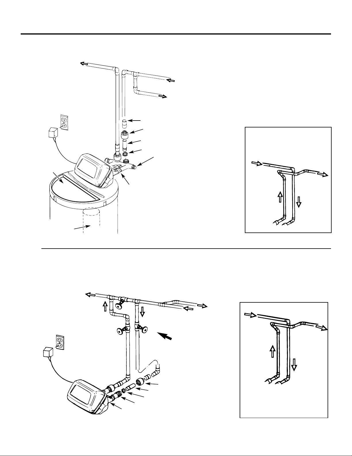
Fig. 1
Installation instructions.
Typical Installation Illustration
Optional 3-Valve Bypass Installation Illustration
Fig. 2
6
Adapters for this installation are not supplied with the softener.
To order these adapters, call GE Parts 800.626.2000.
Ask for part number WS60X10006.
Soft water
Hard water to
outside faucets
MAIN WATER PIPE
Hard water
Installation nut (2)
Copper tube, 3/4″(2)
Washer (2)
Bypass Valve
• Pull out for soft water service
• Push in for bypass
NOTE:
Threads on the bypass valve
are 1″male pipe. If 1″pipes are
needed, do not use the copper tubes
and nuts included. Buy 1″ pipe thread
female adapter, and plumb directly to
1″ threads.
INLET
Brinewell
NOTE:
See
Drain Hose
Connections
section.
SALT
GOES HERE
Salt hole
cover
removed
24V transformer
120-volt outlet
Hard water
Soft water
From softener outlet
To softener inlet
CROSS-OVER
Use if water supply flows from the left.
Include single or 3-valve bypass.
Hard water
Soft water
From softener outlet
To softener inlet
CROSS-OVER
Use if water supply flows from the left.
Include single or 3-valve bypass.
MAIN WATER PIPE
Soft water
Hard water
Copper tube, 3/4″(2)
Washer (2)
Installation adapter (2) (see above)
INLET
NOTE:
Threads on the installation adapters are 1″male pipe. If 1″ pipes are
needed, do not use the copper tubes and nuts included. Buy 1″pipe thread
female adapter, and plumb directly to 1″threads on installation adapters.
24V transformer
120-volt outlet
Bypass valve
Hard water to outside faucets
Inlet valve
Outlet valve
Nut (2)
3-valve bypass system
For soft water service:
• Open the inlet and outlet valves
• Close the bypass valve
For bypass hard water:
• Close the inlet and outlet valves
• Open the bypass valve
Union (2) (not supplied)
Page 7
Step-by-step installation instructions.
• Turn off the gas or electric supply to the water heater, in the possibility that the
water heater may be drained while draining pipes.
• Turn off the water supply to pipes to be cut and drain the house water pipes.
• Open both hot and cold faucets.
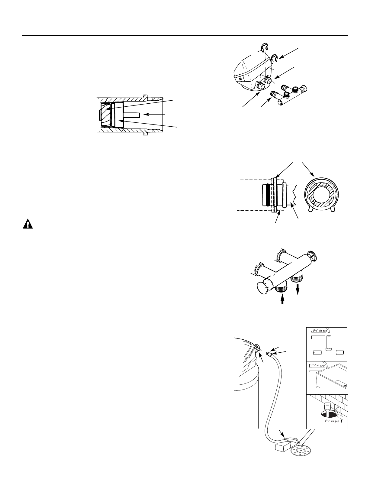
1. INSTALL BYPASS VALVE
• Remove plastic shipping plug and wire from valve outlet.
• Push the bypass valve (lubricate o-ring seals with silicone grease) into both ports
of the valve as shown in Fig. 3A.
• Snap the 2 large plastic clips in place, from the top, down as shown in Figures 3A
and 3B. Be sure they snap into place. Pull on the bypass valve to make sure it is
held securely in place.
2. MOVE THE SOFTENER ASSEMBLY INTO INSTALLATION POSITION:
• Be sure the installation surface is level and smooth. Sharp objects under the tank
may puncture it. If needed, place the tank on a section of 3/4″thick (minimum)
plywood. Then, place shims under the plywood as needed to level the softener.
3. PLUMB IN AND OUT PIPES TO AND FROM SOFTENER:
CAUTION: Observe all of the following cautions as you connect inlet and
outlet plumbing. See Fig. 1 or 2.
• BE SURE INCOMING HARD WATER SUPPLY IS DIRECTED TO THE
SOFTENER VALVE INLET PORT. If house water flow is from the left, use a
plumbing cross-over as shown in Fig. 1.
• If making a soldered copper installation, do all sweat soldering before
connecting pipes to the bypass valve. Torch heat will damage plastic parts.
• When turning threaded pipe fittings onto plastic fittings, use care not to cross-
thread.
• Use pipe joint compound on all external pipe threads.
• Support inlet and outlet plumbing in some manner (use pipe hangers) to keep
the weight off of the valve fittings.
4. CONNECT AND RUN THE VALVE DRAIN HOSE:
• Use the provided drain hose (20′length included) to attach to the valve drain
fitting. To keep water pressure from blowing the hose off, use a hose clamp to
secure in place.
• Locate the other end of the hose at a suitable drain point (floor drain, sump,
laundry tub, etc.) that terminates at the sewer. Check and comply with local codes.
IMPORTANT: If more drain hose is needed, it should be ordered from GE Parts
at 800.626.2002. The water softener will not work if water cannot exit this hose
during regenerations.
• Tie or wire the hose in place at the drain point. High water pressure will cause it
to whip during the back-wash and fast rinse cycles of regeneration. Also provide
an air gap of at least 1–1/2″between the end of the hose and the drain point. An
air gap prevents possible siphoning of sewer water into the softener, if the sewer
should “back-up.”
• If raising the drain hose overhead is required to get to the drain point, do not
raise higher than 8′above the floor. Elevating the hose may cause a back-pressure
that could reduce brine draw during regenerations.
Fig. 3A
Fig. 3B
Fig. 3C
Fig. 4
NOTE: Be sure the turbine
and support are firmly in
place in the valve outlet.
Blow into the valve port
and observe the turbine
for free rotation.
Drain
fitting
on
valve
Valve
drain
hose
FLOOR DRAIN
Turbine
Valve outlet
Turbine shaft
and support
IN
OUT
Turn bypass valve
upside down to
connect to floor
level plumbing
Valve body inlet or
outlet
Bypass valve
(push all the way in)
Clip
END
VIEW
Clip
Outlet
Inlet
O-ring seal goes into
the outer groove only.
The clip snaps into the
inner groove (see
below).
Bypass valve
NOTE:
Threads on the
bypass valve are 1″male
pipe. If 1″pipes are needed,
do not use the copper tubes
and nuts included. Buy 1″
pipe thread female adapter,
and plumb directly to 1″
threads.
SIDE
VIEW
Tie or wire hose
in place
STANDPIPE
LAUNDRY TUB
SUMP
7
Clamp
1
1
⁄2″air gap
Page 8
Step-by-step installation instructions.
8
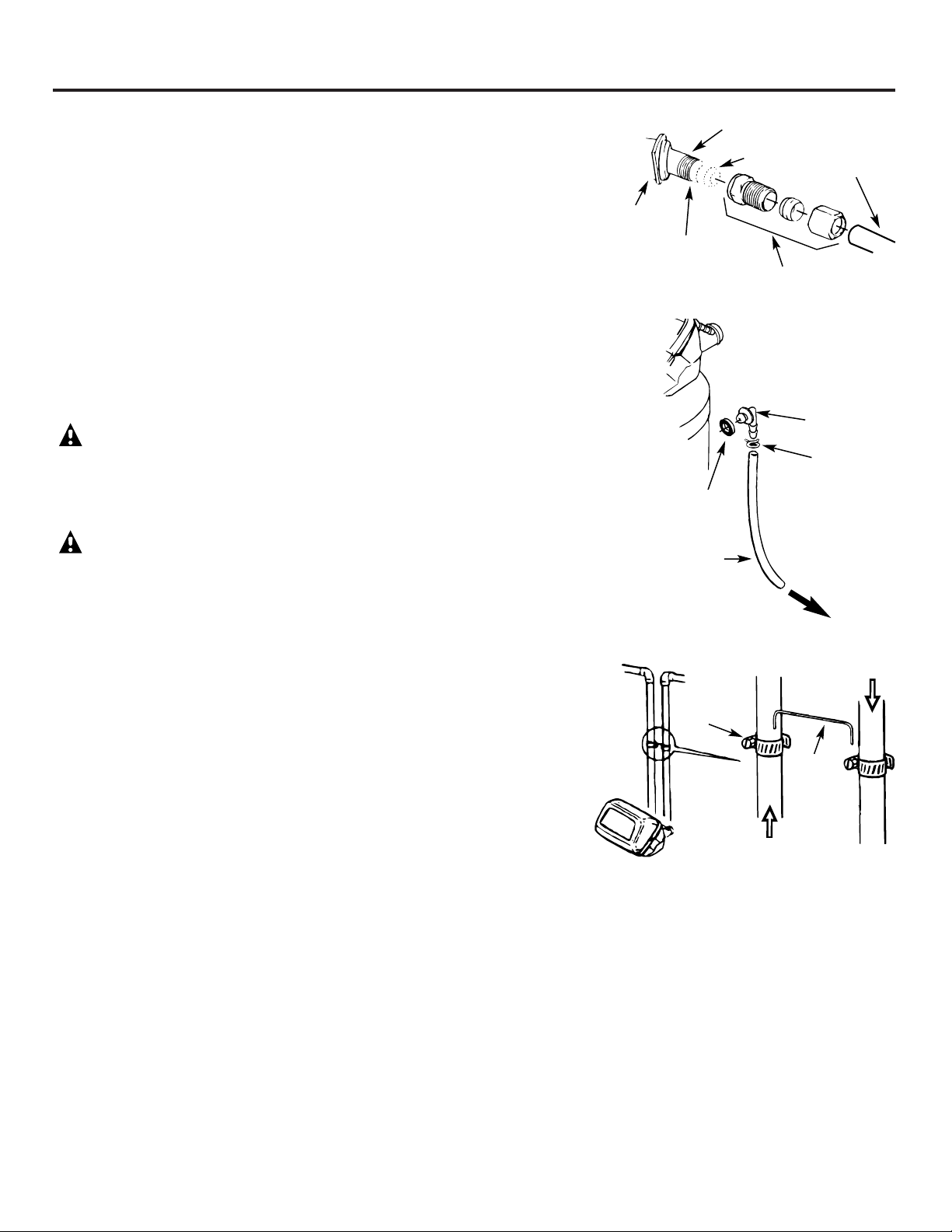
4A. CONNECTING A RIGID VALVE DRAIN TUBE
• To adapt a copper drain tube to the softener, use a hacksaw to cut the barbed end from the
drain fitting as shown in Fig. 4A. Rotate the drain fitting so the cutting blade clears the valve
housing to prevent damage to valve. Buy a compression fitting (1/4″female pipe thread x
1/2″O.D. tube) and needed tubing from your local hardware store.
5. INSTALL THE BRINE TANK OVERFLOW FITTINGS AND HOSE
• Insert the rubber grommet into the 3/4″ diameter hole in the brine tank sidewall as shown
in Fig. 5.
• Push the end of the hose adapter elbow into the grommet as shown in Fig. 5.
• Attach a length of hose (use remaining hose from Step 4) to the hose adapter elbow. Use a
hose clamp to hold it in place.
• Locate the other end of the hose at the drain point. DO NOT ELEVATE this hose higher
than the elbow on the brine tank.
IMPORTANT: DO NOT TEE OVERFLOW HOSE TO VALVE DRAIN HOSE.
NOTE: This drain is for safety only. If the cabinet (brine tank) should over-fill with water, the
excess is carried to the drain.
6. INSTALL GROUNDING CLAMPS AND WIRE
DANGER: Failure to properly attach ground wire could result in electrical shock.
• If plumbing is metal, to maintain electrical ground continuity in the house cold water
piping, install the included ground clamps as shown in Fig. 6. Be sure the pipes are
clean under the clamps to assure good contact.
7. FLUSH PIPES, EXPEL AIR FROM SOFTENER, AND TEST YOUR INSTALLATION
FOR WATER LEAKS:
CAUTION: To avoid water or air pressure damage to softener inner parts, be sure to
do the following steps in exact order.
A. Fully open 2 cold soft water faucets nearby the softener.
B. Place bypass valve in “bypass” position by pushing the stem inward.
C. Fully open the house main water pipe shutoff valve. Observe a steady flow from both
faucets opened in step A, above.
D. Place bypass valve in the “service” position EXACTLY as follows. KEEP SOFT WATER
FAUCETS OPEN.
SLOWLY pull or slide the valve stem (out) toward the service position pausing several
times to allow the softener to pressurize slowly.
E. After about 3 minutes, open a HOT water faucet for 1 minute, or until all air is expelled,
then close. NOTE: If water appears cloudy or has salty taste,allow to run for several more
minutes, or until clear.
F. Close all water faucets.
G. Check your plumbing work for leaks and fix right away if any are found. Be sure to
observe previous caution notes.
H. Turn on the gas or electric supply to the water heater. Light the pilot, if applicable.
Fig. 4A
Fig. 5
Fig. 6
Clamp (2)
Ground
wire
From valve outlet
To valve inlet
To sewer
drain
Overflow drain hose
Hose clamp
Grommet
Clip
1/4″NPT threads
Barbs
1/2″O.D.
copper tube (not
furnished)
Cut barbs
from drain
fitting
Compression fitting, 1/4″
NPT X 1/2″O.D. tube (not
furnished)
Do not connect to valve
drain hose.
8. ADD WATER AND SALT TO THE BRINE TANK:
• Lift the cabinet (brine tank) cover. Add about 3 gallons of water into the tank. Do not add into the brinewell.
• Fill tank with NUGGET, PELLET or coarse SOLAR water softener salt with a purity of 99.5% or higher. Do not use rock, block, granulated, and
ice cream-making salts, or salt with iron-removing additives (except for Diamond Crystal® Red•Out® brand salt). Salt storage capacity is
approximately 200 lbs. Keep the salt hole cover in place on the softener unless servicing the unit or refilling with salt.
NOTE: If the softener is installed in a humid basement or other damp area, it is better to fill the tank with less salt, more frequently. Eighty to 100
lbs. of salt will last for several months, depending on water hardness, family size and water softening system model.
9. CONNECT TO ELECTRICAL POWER:
• If transformer wiring is not visible at the back of the control head, remove control cover. DO NOT PULL ON OR DISCONNECT WIRING.
Locate the long wire with“U” shaped connectors on one end. Route this wire through the rear of the control housing. Replace the control
cover.
• Fasten the 2 power cable lugs (“U” shaped connectors) to the 2 screws on the transformer, and tighten the screws. Then, plug the transformer
into the electrical outlet.
• The softener works on 24 volt-60Hz electric power. The included transformer changes standard 120 volt AC house power to 24 volts. Plug the
transformer into a 120 volt outlet only. Be sure the outlet is always live so it can not be switched off by mistake.
10. PROGRAM THE TIMER:
• See Programming the Timer section.
Hose adapter
Page 9
9
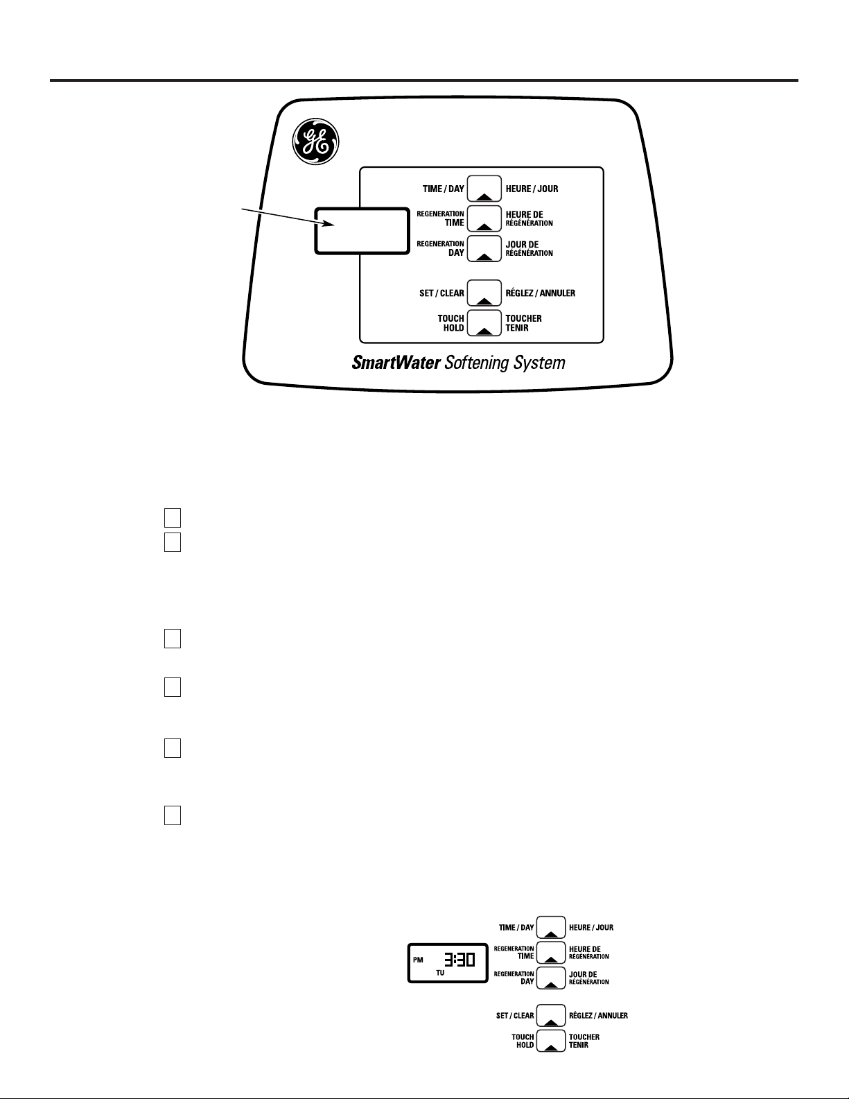
Programming the Timer
Set the timer:
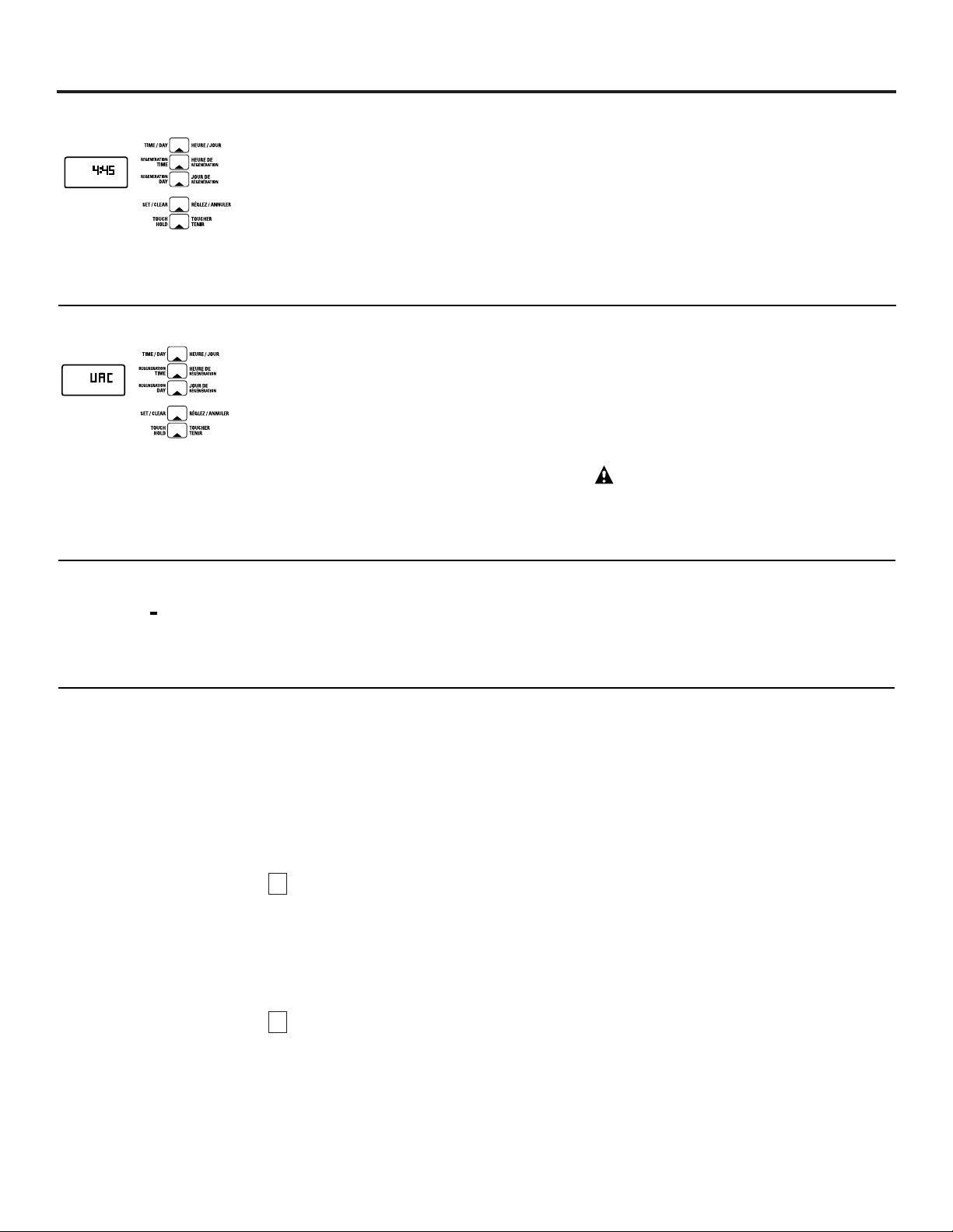
When the transformer is plugged into electrical outlet, 12:00AM, SUnday will begin to flash in the time display.
Set the time of day and present day of week as follows:
A.
Set the time of day:
Press the
TIME/DAY
b
utton once and the hour display will begin to flash.
Press the
SET/CLEAR
b
utton until the present hour of the day shows in the display. Be sure AMshows
for morning hours, or PMfor afternoon and evening hours.
NOTE:
Press
SET/CLEAR
button and quickly release to move the hour display ahead 1 at a time to
the correct hour. Or, hold the
SET/CLEAR
button to move the display ahead 2 hours each second,
to the correct hour.
Press the
TIME/DAY
b
utton once to steady the hour display, and minutes begin to flash.
Repeat
Step A. 2
to set the correct minutes.
Press the
TIME/DAY
b
utton again to steady the minute display (day will begin flashing). Fig. 7 shows
the timer set at 3:30 PM.
B.
Set the present day of the week:
Press the
SET/CLEAR
b
utton to set the present day of the week in the display.
NOTE:
Press
SET/CLEAR
b
utton and quickly release to move the day display 1 at a time. Or hold the
SET/CLEAR
button to move the day display ahead 2 days each second.
Press the
TIME/DAY
button again to steady the entire display. Fig. 7 shows the timer set at
TUesday.
No other settings are needed
after installing your water softener. The softener is factory set to regenerate
every Monday, Wednesday and Saturday (beginning at 2:00 AM). For most families, this gives enough soft
water for their needs. However, if you want the softener to regenerate at a different time, or on different
days, or to set for the most efficiency, see
About the Water Softener System
section.
2
1
4
3
2
1
See the
Operating
section for other
timer controls and features.
Fig. 7
EXAMPLE: This drawing shows the
present time of day at 3:30 PM,
and the present day on TUesday.
Display
Page 10
Step-by-step installation instructions.
10
Sanitizing Procedures
Care is taken at the factory to keep your softener clean and
sanitary. Materials used to make the softener will not infect
or contaminate your water supply and will not cause
bacteria to form or grow. However, during shipping,
storage, installing and operating, bacteria could get into
the softener. For this reason, sanitizing as follows is
suggested when installing.
NOTE: Sanitizing is recommended by the Water Quality
Association for disinfecting.
Be sure to complete all installation steps, including
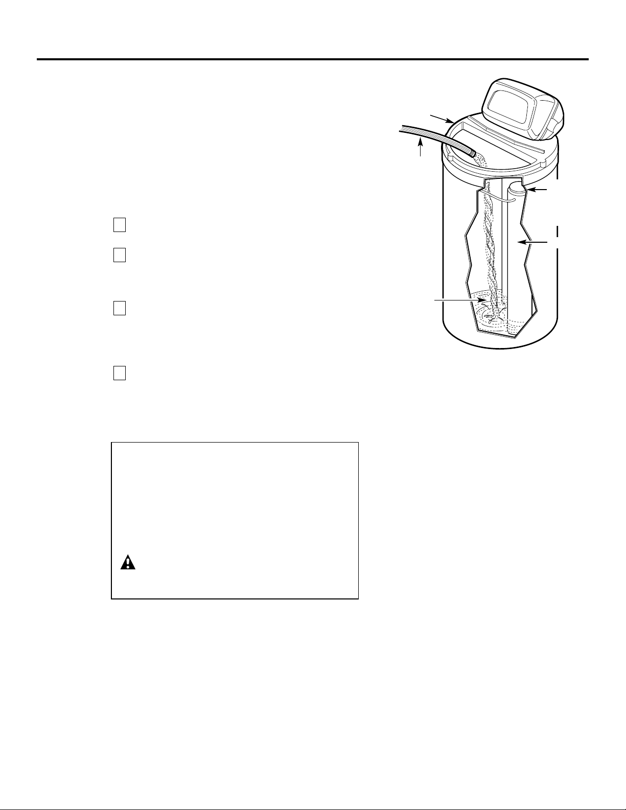
timer programming.
Remove the brinewell cover (see Fig. 8) and pour
about 3/4 ounce (11⁄2 tablespoons) of common 5.25%
household bleach (Clorox, Linco, BoPeep, White Sail,
Eagle, etc.) in the softener
brinewell
.
Press the
TOUCH/HOLD
button and hold for 3 seconds
to start a recharge. This first recharge does
several
things: fills the salt tank to the water level needed,
gets
all the air out of the resin tank, makes the resin bed
ready for service. See the
Recharging
section.
If after sanitation, water from house faucet tastes salty
or has a slight color, this is a preservative from the
resin tank. Turn on the cold soft water faucets and
drain for a few minutes or until clear.
NOTE: This recharge takes about 2 hours.
4
3
2
1
Fig. 8
Salt hole cover
removed
Hose
Brinewell
Brinewell
cover (remove
and add about
3/4 oz. bleach)
Water, about
3 gallons
NOTE:
When the above sanitizing regeneration is over,
your house COLD water supply is fully soft immediately.
However, your water heater is filled with hard water and
as hot water is used, it will refill with soft water. When all
the hard water is replaced in the water heater, hot only
and mixed hot and cold water will be fully soft. If you
want totally soft water immediately, after the above
regeneration, drain the water heater until the water
runs cold.
WARNING:
If you do drain the water heater, use
extreme care as the hot water could cause burns.
Turn the water heater off prior to draining.
Page 11
(See rating decal, located
Rated Capacity* on the Softener)
Amount of high capacity resin (lbs/cu. ft) 31.2/.6
Resin tank nominal size (in., dia. x height) 8 x 40
Service flow rate (gpm) 7.5
Water supply maximum hardness (gpg) 50
Water supply maximum clear water iron (ppm)** 3
Water pressure limits (min.-max. psi) 20-125
Pressure drop at rated service flow (psig) 15
Water temperature maximum (°F) 120
Water supply minimum flow rate (gpm) 3
Regeneration cycle flow rates (gpm)
Fill (flow to brine tank) .3
Brining .19
Brine Rinse .12
Backwash 1.8
Fast Rinse 1.8
}
(flow to drain)
11
Specifications/Dimensions
This system conforms to WQA S-100 for the specific capacity claims as verified and substantiated by test data.
* Testing was performed using pellet grade sodium chloride as the regenerant salt.
** Extent of iron removal may vary with conditions. Use of Diamond Crystal® Red•Out® or Super Iron Out® will
improve iron removal. Refer to
Cleaning Iron Out of the Water Softening System
section.
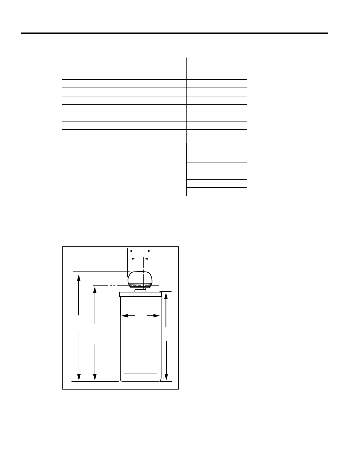
11
1
⁄2″
3
3
⁄8″
OUT
INLET
INLET-OUTLET
48
3
/4″
41
1
⁄4″
18
1
⁄4″
40
1
⁄2″
Page 12
Service
When the
water softening system
is providing soft water, it is called “Service.” During service,
hard water flows from the house main water pipe into the
water softening system
. Inside the
water softening system
resin tank is a bed made up of thousands of tiny, plastic resin beads.
As hard water passes through the bed, each bead attracts and holds the hard minerals. This is
called ion-exchanging. It is much like a magnet attracting and holding metals. Water without
hard minerals (soft water) flows from the
water softening system
and to the house pipes.
After a period of time, the resin beads become coated with hard minerals and they have to be
cleaned. This cleaning is called regeneration, or recharge. Regeneration is started at 2:00 AM
(factory setting) by the
water softening system
control, and consists of five stages or cycles.
These are
FILL, BRINING, BRINE RINSE, BACKWASH
and
FAST RINSE
.
About the water softener system.
12
Automatic Hard Water Bypass During Regeneration
For emergency needs, hard water is available
to the home during the regeneration cycles.
However, you should avoid using HOT water
because the water heater will fill with the
hard water.
Fill Backwash
Salt dissolved in water is called brine. Brine is
needed to clean the hard minerals from resin
beads. To make the brine, water flows into the
salt storage area during the fill stage as shown.
Brining
During brining, brine travels from the salt
storage area into the resin tank. Brine is the
cleaning agent needed to remove hard
minerals from the resin beads. The hard
minerals and brine are discharged to
the drain.
The nozzle and venturi create a suction to
move the brine, maintaining a very slow
rate to get the best resin cleaning with the
least salt.
Brine Rinse
After a pre-measured amount of brine is
used, the brine valve closes. Water continues
to flow in the same path as during brining,
except for the discontinued brine flow. Hard
minerals and brine flush from the resin tank
to the drain.
During backwash, water travels upthrough
the resin tank at a fast flow rate, flushing
accumulated iron, dirt, and sediments from
the resin bed and to drain.
Fast Rinse
Backwash is followed by a fast flow of water
down
through the resin tank. The fast flow
flushes brine from the bottom of tank, and
packs the resin bed.
After fast rinse, the
water softening system
returns to soft water service.
Soft water
OUT
Salt storage
tank (salt
not shown)
Brine
valve
Hard water
IN
Resin
tank
Resin
bed
Soft water
OUT
Hard water
IN
Salt
storage
tank
Fill
water
Brine
valve
Hard water
bypass OUT
Nozzle &
venturi
Hard water
IN
Brine
valve
Brine
Drain
Drain
Hard water
bypass OUT
Hard water
IN
Drain
Soft water
OUT
Hard water
IN
Page 13
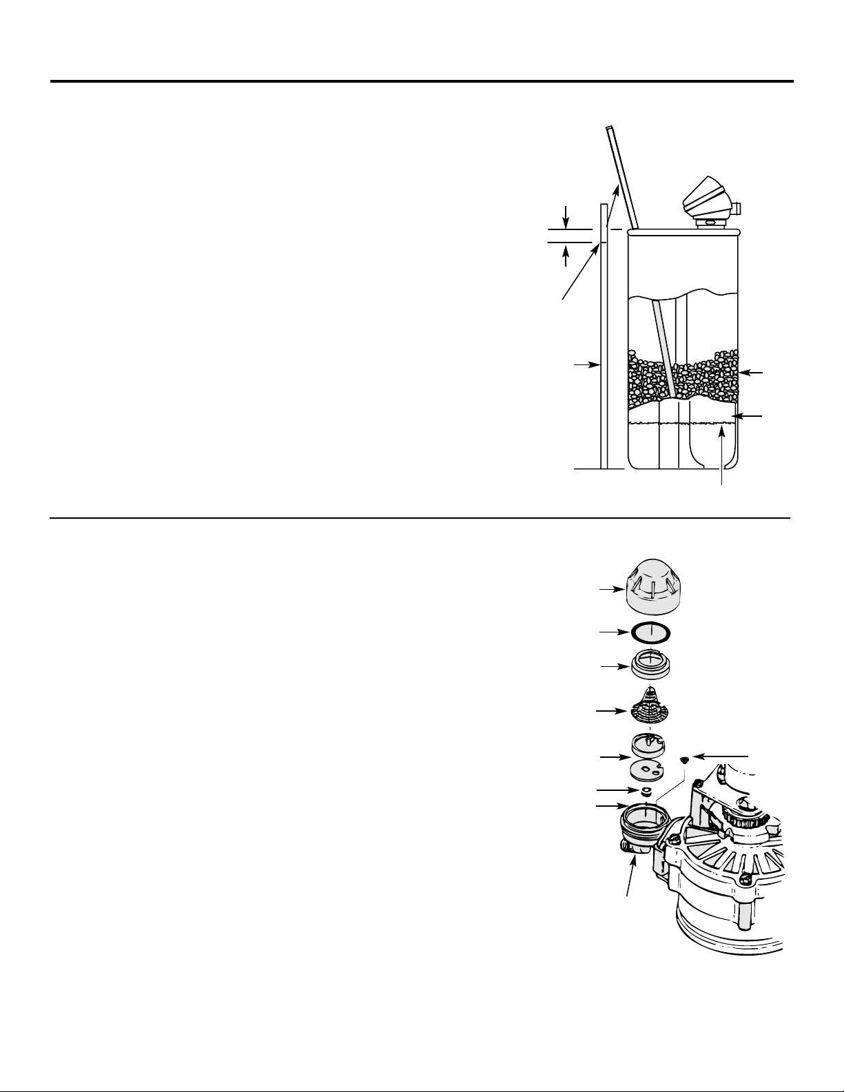
Cleaning the Nozzle and Venturi Assembly
A clean nozzle and venturi is needed for the water softening system to
work properly.
This small unit makes the suction to move brine from
the salt storage area to the resin tank during regeneration. If it
becomes plugged with sand, dirt, etc., the water softening system
will not work and you will get hard water.
To get to the nozzle and venturi, remove the water softening system
top cover. Be sure the water softening system is in service cycle (no
water pressure at nozzle and venturi). Then, while holding the
nozzle and venturi housing with one hand, remove the cap. Lift out
the screen support and screen, then the nozzle and venturi. Wash
and rinse the parts in warm water until clean. If needed, use a small
brush to remove iron or dirt. Also check and clean the gasket.
NOTE:
Some models have a small flow plug located in the nozzle and
venturi, and/or a small cone shaped screen in the housing. Be sure
to check and clean these parts, if your model is so equipped.
Carefully replace all parts in the correct order. Lightly lubricate the
o-ring seal with clean silicone grease or petroleum jelly and place in
position.
Install and tighten the cap, by hand only. Do not over-tighten
the cap or housing.
IMPORTANT: Be sure small holes in the gasket are
centered directly over the small holes in the nozzle and
venturi housing.
*Install with numbered side up, concave side down.
Cap
O-ring seal
Screen support
Screen
Screen
Nozzle & Venturi
Nozzle & Venturi housing
Gasket
*Fill Flow plug
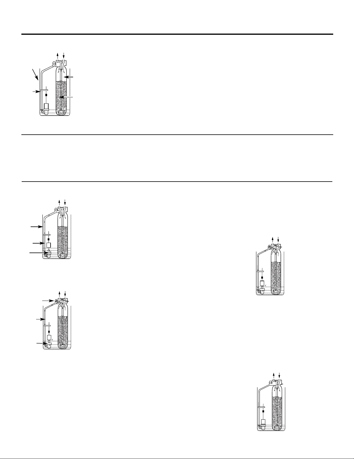
Breaking a Salt Bridge
Sometimes, a hard crust or salt bridge forms in the salt storage area.
It is usually caused
by high humidity or the wrong kind of salt. When
the salt bridges, an empty space forms
between the water and salt.
Then salt will not dissolve in the water to make brine.
If the brine tank is full of salt, it is hard to tell if you have a salt
bridge. Salt is loose on top, but the bridge is under it. The following
is the best way to check for a salt bridge.
Salt should be loose all the way to the bottom of the tank. Take a
broom handle or like
tool, and carefully push it down into the salt,
working it up and down. If the tool strikes a
hard object (be sure it’s
not the bottom or sides of the tank), it’s most likely a salt bridge.
Carefully break the bridge with the tool.
Do not
pound on the walls
of the tank.
If the wrong kind of salt made the bridge, take it out. Then fill the
tank with nugget or pellet salt only. In humid areas, it is best to fill
with less salt, more often.
Push tool into salt
bridge to break
Pencil
mark
Broom
handle
Salt
Salt
bridge
Water level
1″ – 2″
13
Page 14
14
If electrical power to the timer goes off, the
memory built into the timer circuitry keeps
all settings for six hours (minimum) or more.
The display is blank and softener will not
regenerate.
When electrical power comes on…one of two
things will happen.
The present time of day will show, meaning
the timer memory has kept all settings.
NOTE:
If the softener was in a regeneration
when the power was lost, it will now finish
the cycle.
OR
The display will show a flashing time.
The timer memory did not keep the time
settings and they must be reset. See the
Program the Timer
section.
NOTE:
When the power comes on, the
flashing display returns to a time of
12:00 AM Sunday, then begins to keep
time again. If you do not reset all time
settings, the softener will regenerate three
days each week. However, regeneration
will most likely be on the wrong days and
at the wrong time.
If the softener was in a regeneration when
the power went off, the valve will return to
service position without finishing the
regeneration cycle.
If your water tastes salty:
—use
RECHARGE NOW
to start another
regeneration. See the
Recharging
section.
—open one or more soft water faucets and
allow to run until the salt taste is gone.
2
1
About the face plate timer features.
Recharging
If you have guests visiting, or other times when you use more water than usual, you could begin
to run out of soft water. If the softener is not scheduled to regenerate for another day or two,
you would get hard water until then. If this happens, or you think it might happen, press and
hold in the
TOUCH HOLD
button for three seconds until
RCHG
shows.
RCHG
will flash in the display
during the regeneration, which lasts under two hours.
NOTE:
Avoid using
HOT
water while the softener regenerates, because bypass hard water will refill
the water heater, see the
Automatic Bypass
section.
PM
RCHG
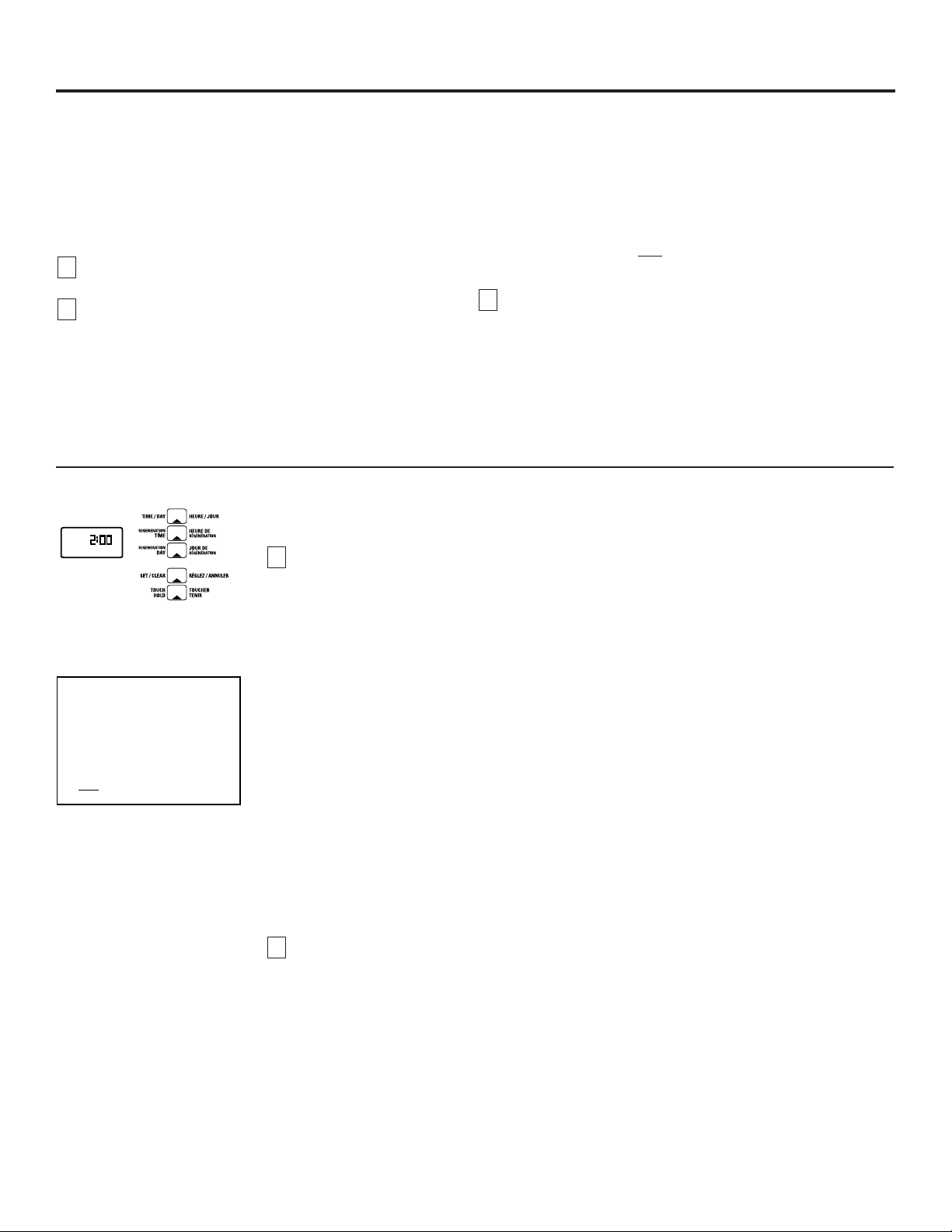
Going on Vacation?
The day you leave on vacation, or for a long
absence, press (do not hold) the
TOUCH HOLD
button.
VAC
begins to flash in the display. The
timer will keep time, but the softener will not
regenerate.
NOTE:
While on vacation, the softener will go
through a regeneration if the
RECHARGE NOW
feature is used.
To shut off the water supply to the softener,
use the plumbing bypass valve.
When you return, press the
VACATION
button
again to return the softener to service and also
return the softener to the correct time of day
in the display.
WARNING:
Remember to do this or the
softener will not regenerate and you will
soon have hard water.
Error Code
An error code could appear in the face plate display if a problem occurs in the softener electronics.
If you see an error code instead of the present time of day, see the
Trouble Shooting Tips
section or
call the GE Answer Center 800.626.2000 for service.
E
E
What to Do When a Power Outage Occurs
PM
RCHG
Page 15
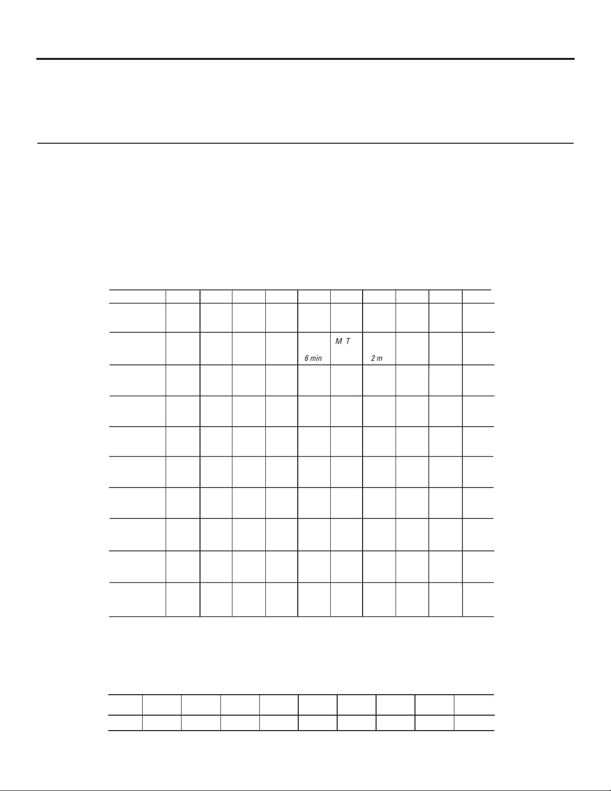
Setting the Timer for Days and Fill Minutes of Regeneration
NOTE:
The timer is factory set for Monday, Wednesday and Saturday with regenerations starting
at 2:00 AM. Fill time is factory set for 16 minutes.
Set days and time of regeneration or recharge.
Step 1—
Press the
REGENERATION TIME
button once to display the factory set regeneration days
and starting time (flashing). To change the regeneration start time, do
Step 2
following
this. Otherwise go to
Step 3.
NOTE:
See
Automatic Bypass
section, when choosing a regeneration starting time other
than 2:00 AM.
Step 2—
Press the
SET/CLEAR
button until the desired regeneration starting time shows in
the display.
NOTE:
Press
SET/CLEAR
and quickly release to move the display ahead 1 hour at a
time.
Or, hold the
SET/CLEAR
button to move display ahead 2 hours each
second.
Step 3—
Press the
REGENERATION DAY
button and
SUnday
begins to flash.
—
If you do want regenerations on Sunday, see the
Regeneration Chart
, press the
SET/CLEAR
button to display
ON.
—
If you do
NOT
want regenerations on Sunday, press
SET/CLEAR
button to display
OFF.
Step 4—
Press
REGENERATION DAY
button again to display a flashing
MOnday
and
ON
(factory set
recharge). Use the
SET/CLEAR
button to change display from ONto
OFF
or from
OFF
to
ON.
Step 5—
Press
RECHARGE DAY
button to display a flashing
TUesday, WEdnesday,
etc., each time
using the
SET/CLEAR
button to display either ONor
OFF
as needed.
Set the Fill Cycle Minutes
Step 1—
Press and hold the
REGENERATION TIME
button until
FILL
shows in the display, then
release button. After a few seconds, the fill cycle minutes (factory setting…8) will flash.
Step 2—
Press the
SET/CLEAR
button to set the minutes of fill cycle needed, as shown in the
Regeneration Chart
section.
NOTE:
You may get hard water between regenerations if you set the timer for fewer fill
minutes than the
Regeneration Chart
shows you to set. A higher setting than needed will
waste salt.
NOTE:
Press
SET/CLEAR
and quickly release to move the display ahead 1 minute at a time.
Or, hold the
SET/CLEAR
button to move the display ahead 2 minutes each second.
The display begins over at 0 after passing 59.
2
1
15
It is not hard to fine-tune your softener, but it does take a few
minutes of your time to do it right.
Read the following carefully.
To have soft water all the time, the softener must regenerate,
or recharge a certain number of times in each seven day
period. How many times to regenerate (set the timer) depends
on three things:
The number of people in your home tells you how much
water is used.
The grains per gallon (GPG) hardness of your water
supply.
NOTE: If your water supply contains iron, compensate for it by
adding to the water hardness number. For example, assume
your water is 15 gpg hard and contains 2 ppm iron. Add 5 to
the hardness number for each 1 ppm of iron, thus making the
example water hardness number 25.
You can get the grains per gallon (gpg) hardness of your water
supply from a water analysis laboratory, or call and ask your
local water department, if you are on a municipal supply, or
call GE Answer Center®to request a water hardness test kit.
If your report shows hardness in parts per million (ppm) simply
divide by 17.1 to get the equivalent number of grains per gallon.
15 gpg hardness
2 ppm iron x 5 = 10 +10
(times) 25 HARDNESS NUMBER
How much salt used in each regeneration is determined
by the length of the fill cycle. See the
Regeneration Chart
section.
3
2
1
About regenerating the system.
AM
MO
WE SA
Write in your results here.
1. M T W TH F S SU
—circle suggested days—
Suggested days to regenerate
2.
Fill Cycle minutes needed
Page 16
16
About regenerating the system.
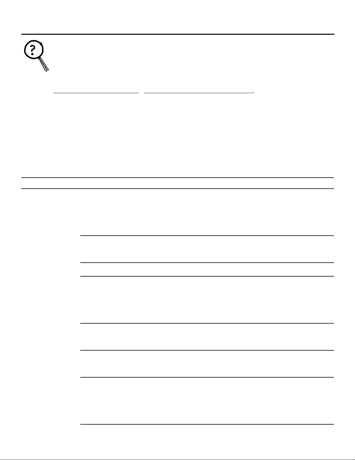
Regeneration Chart
This makes it easy for you to pick the best regeneration and fill time setting to use.
Step 1—
Go down the side of the chart to the number of persons in your family, or the number of people
in the house using water.
Step 2—
Across the top of the chart, find the column listing the grains per gallon hardness of your water,
or hardness number for iron water.
Step 3—
Read across and down the chart to find the point where
Steps 1
and 2meet. At this point,
suggested days to regenerate, and fill cycle minutes needed are shown.
Up to 5 6 to 10 11 to 15 16 to 20 21 to 25 26 to 30 31 to 35 36 to 40 41 to 45 46 to 50
M
2 min.
M
2 min.
M
2 min.
M
2 min.
M
3 min.
M
3 min.
M
4 min.
M
5 min.
M TH
2 min.
M TH
3 min.
M
2 min.
M
2 min.
M
3 min.
M
5 min.
M TH
3 min.
M TH
3 min.
M W S
2 min.
M W S
3 min.
M W S
3 min.
M T TH
F S
2 min.
M
2 min.
M
3 min.
M TH
2 min.
M TH
3 min.
M W S
3 min.
M W S
3 min.
M W S
3 min.
M T TH
S
3 min.
M T TH
F S SU
2 min.
M T TH
F S
3 min.
M
2 min.
M
5 min.
M TH
3 min.
M W S
3 min.
M T TH
F S
2 min.
M W S
2 min.
M T TH
F S SU
2 min.
Every
Day
2 min.
M T TH
F S SU
3 min.
Every
Day
3 min.
M
3 min.
M TH
6 min.
M W S
3 min.
M T TH
F S
2 min.
M T TH
F S SU
2 min.
M T TH
S
3 min.
M T TH
F S SU
3 min.
Every
Day
3 min.
Every
Day
4 min.
Every
Day
4 min.
M
3 min.
M TH
3 min.
M W S
3 min.
M T TH
S
3 min.
M T TH
F S
3 min.
M T TH
F S SU
3 min.
Every
Day
3 min.
Every
Day
4 min.
Every
Day
5 min.
Every
Day
7 min.
M
4 min.
M W S
2 min.
M W S
3 min.
M T TH
F S SU
2 min.
M T TH
F S SU
3 min.
Every
Day
3 min.
Every
Day
4 min.
Every
Day
5 min.
Every
Day
8 min.
M
5 min.
M W S
3 min.
M T TH
S
3 min.
Every
Day
2 min.
Every
Day
3 min.
Every
Day
4 min.
Every
Day
5 min.
Every
Day
8 min.
M TH
2 min.
M W S
3 min.
M T TH
F S SU
2 min.
M T TH
F S SU
3 min.
Every
Day
4 min.
Every
Day
5 min.
Every
Day
8 min.
M TH
6 min.
M T TH
F S
2 min.
M T TH
F S
3 min.
Every
Day
3 min.
Every
Day
4 min.
Every
Day
7 min.
Step 3—
Press
TIME/DAY
button to return the present time and day display.
To set the present time of day and day of week see
Program the Timer
section.
If you need help to program the timer, call the GE Answer Center 800.626.2000.
# in household
1
2
3
4
5
6
7
8
9
10
Water Hardness—Grains Per Gallon
Days to Regenerate:
M=Monday, T=Tuesday, W=Wednesday, TH=Thursday, F=Friday, S=Saturday, SU=Sunday
(factory set for Monday, Wednesday and Saturday)
Min.= length of fill cycle needed (factory set for 8 minutes)
Salt
usage
Time
1.8 pounds 2.7 pounds 3.6 pounds 4.5 pounds 5.4 pounds 6.3 pounds 7.2 pounds 8.1 pounds 9.0 pounds
2 minutes 3 minutes 4 minutes 5 minutes 6 minutes 7 minutes 8 minutes 9 minutes10minutes
Pounds of Salt Used Each Regeneration
Minutes of Fill is at 0.3 GPM
Page 17

17
Care and cleaning of the water softening system.
Checking the Salt Storage Level and Refilling
Brine (salt dissolved in water) is needed for each and every regeneration. The water for making brine is
metered into the salt storage area by the water softening system valve and control.
However, you must keep the
tank supplied with salt.
When to refill with salt:
Check the salt level a few weeks after you install the water softening system and every
week after that. Refill when the brine tank is from 1/3 to 1/2 full. In humid areas it is best to fill with less salt
more often. Never allow the water softening system to use all the salt before you refill it. Without salt, you will
soon have hard water.
Use clean water softening salts only, at least 99.5% pure. NUGGET, PELLET or coarse SOLAR salts are
recommended.
Do not use rock, block, granulated or ice cream making salts.
They contain dirt and sediments,
or mush and cake, and will create maintenance problems.
CAUTION: Water softening salt with iron removing additives:
Some salts may have an additive to help the
water softening system handle iron in the water supply. Although this additive may help to keep the water
softening system resin clean, it may also release corrosive fumes that weaken and shorten the life of some
water softening system parts. GE recommends using only Diamond Crystal® Red•Out® brand salt.
Your water softening system takes hardness minerals (calcium and magnesium) out of the water. Also, it can
control some (see
Specification Guidelines
section) “clear water” iron. With clear water iron, water from a faucet
is clear when first put into a glass. After 15 to 30 minutes, the water begins to cloud or turn rust colored.
A water softening system
will not
remove any iron that makes the water cloudy or rusty as it comes from the
faucet (called red water iron). To take red water iron out of water, or over the maximum of clear water iron,
an iron filter or other equipment is needed.
GE recommends using only Diamond Crystal® Red•Out® brand salts with Iron Fighter® additive to help keep
the resin bed clean of clear iron. If your water supply has clear water iron, periodic resin bed cleaning is needed.
GE recommends using Super Iron Out® brand resin bed cleaner to thoroughly clean your resin bed if your
iron content is high. Clean the bed at least every six months, or more often if iron appears in the soft water
between cleanings.
IMPORTANT:
It is important to mix the resin bed cleaner with water (following the manufacturer’s instructions),
pour it into the
brine well tube
(see page 6) and regenerate the softener immediately. Do not pour the resin bed
cleaner in with the salt, as it will not be as effective in cleaning the resin, and can cause damage to the softener
if it is left in the brine tank for an extended period due to the corrosive gases that are formed.
Cleaning Iron Out of the Water Softening System
Page 18
18
Before you call for service…
Troubleshooting Tips
Save time and money! Review the chart on this
page first and you may not need to call for service.
Problem Possible Causes What To Do
No soft water
Faucet or fixture where sample was •
To conserve salt, the installer
may have isolated some fixtures
taken not plumbed to soft water.
(outside faucets, toilets, etc.)
from soft water. From the outlet
NOTE:
Be sure sample is from a faucet
of the water softening system, trace the water flow path in
that does not mix soft and hard water.
house plumbing. If soft water is not directed to a faucet or
For example, a single lever kitchen faucet,
fixture where wanted, consult a plumber.
if the cold side is plumbed to hard water.
No salt in the storage tank. •Refill with salt. See the
Step-by-Step Installation Instructions.
Use the
TOUCH HOLD
button to start a regeneration.
See the
About the Face Plate Timer
section.
Salt in storage tank bridged. •See the
Breaking a Salt Bridge
section.
Transformer unplugged at wall outlet
•Check for a loss of electrical power to the water softening
or
power cable to softener not system, due to any of these conditions and correct as needed.
connected. Fuse blown or circuit With the power supply restored, observe the faceplate time
breaker popped on circuit to electrical display and read
Program Memory
section.
outlet. Electrical outlet on a circuit that
NOTE: The electrical outlet for the softener should be continuously
can be switched off.
live
so it cannot be accidentally switched off.
Manual bypass valve in bypass •Be sure the bypass valve stem
is positioned properly, with the
position.
knob in the OUT position. Observe i
nstructions on the decal
at the end of the stem.
Valve drain hose pinched, plugged, •
Any restriction in this drain hose
may prevent proper operation
elevated too high or otherwise
of the
nozzle and venturi and reduce or prevent brine draw
restricted. during regenerations.
Nozzle and venturi dirty, incorrectly •Refer to
Cleaning the Nozzle and Venturi Assembly
instructions.
assembled or damaged.
With water pressure to the
water softening system off, take the
nozzle assembly apart. Inspect, clean and replace as needed.
Any foreign particle(s), scratches, nicks, etc., in the passages
can
prevent operation. Be sure holes in the gasket are centered
over holes in the housing.
Timer in the vacation (VAC) • See
VACATION
feature to return the softener to service.
position.
See the
About the Face Plate Timer
section.
NO SOFT WATER – Most Common Problems
:
Check the following before calling for service
•
Salt in softener...at least 1/3 full.
•
By pass valve in “Service” position. Knob should be in the OUT position.
•
Check hardness setting in control. Verify hardness of supply water.
Water hardness can vary throughout the year.
•
Salt Bridge, water not in contact with salt (see Breaking a Salt Bridge section).
Page 19
19
Problem Possible Causes What To Do
Water hard sometimes
Using hot water while the water •Avoid using hot water during water softening system
softening system is regenerating regenerations because the water heater will refill with
hard water. See
Automatic Hard Water Bypass During
Regeneration
section.
Too few regenerations or more •See
Regeneration Chart
for correct setting.
water being used
Grains of hardness in your water •
Water hardness can change
over time, especially in well water.
supply have increased To check, have the water tested by a water analysis laboratory
or call your local water department. Adjust the timer settings
as needed. See
Regeneration Chart
.
Water feels slippery
Absence of hardness minerals •This is normal.
after installation of
water softening system
Water softening system
Water softening system is a •Does not use much salt to regenerate—very efficient.
not using any salt
“demand” unit
Possible salt bridge •See the
Operating Instructions, Tips
section.
Possible plugged nozzle and venturi •See the
Operating Instructions, Tips
section.
Water is blue color
Acidic water in copper plumbing •Have the water tested at once.
after water softening
system was installed WARNING:
Do not drink the water until
problem has
been corrected.
Water softening system
Meter turbine stuck •Call for service.
not regenerating
Sensor wire corroded •Call for service.
No power to unit •Check the circuit breaker or fuses.
Mechanical defect •Call for service.
Cloudiness on glassware
Combination of soft water and •This is called
etching
and is permanent. To prevent this
(automatic dishwashers)
too much detergent from happening, use less detergent if you have soft water.
Wash glassware in the shortest cycle that will get them clean.
Salty tasting water
Insufficient backwash and •Press and hold
TOUCH or HOLD
button until
RECHARGE
after installation
rinse time starts to flash to start a regeneration.
•At completion of regeneration cycle (approx. 2 hrs) run water
from faucets to purge the salty water.
Low water pressure •Check pressure; should be minimum 20 psi.
Restricted drain hose •Clean and reconnect hose.
Page 20
20
Before you call for service…
Problem Possible Causes What To Do
Resin beads showing
Cracked distributor •Call for service.
up in drinking water
and sink
Sounds you might hear
Running water from the unit •This is normal.
into a drain
Water has air bubbles
Air in system after installation •Will go away after it runs for a while.
and is cloudy
Error Code on control
Wiring may have worked loose •Unplug transformer.
in control
•Remove control cover, release clips on side.
•Check for loose/incorrect wiring connections to electronic
board or switch. Reconnect as required.
•Reassemble control cover.
•Plug in Transformer.
•Wait six minutes for Error Code to reappear.
•If Error Code reappears call for service.
Troubleshooting Tips
Page 21
21
Parts list.
Page 22
Parts list.
22
153
Page 23

23
Parts catalog.
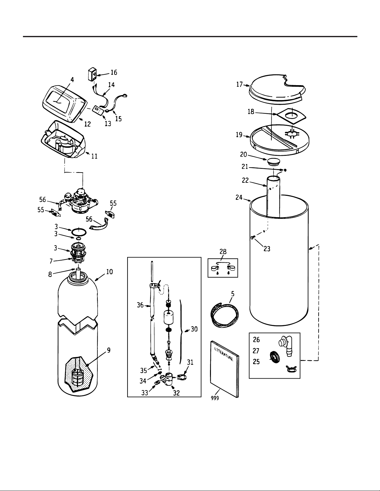
REF. NO. PART NO. PART DESCRIPTION
0003 WS35X10001 O-RING SEAL KIT 1
0004 DECAL 1
0005 WS07X10004 HOSE DRAIN, 20 FT. 1
0007 WS14X10002 DISTRIBUTOR TOP 1
0008 WS14X10001 DISTRIBUTOR BOTTOM 1
0009 WS01X10002 RESIN - 1 CU. FT. 1
0010 WS32X10001 TANK RESIN 1
0011 WS31X10001 COVER BOTTOM 1
0012 WS31X10002 COVER CONTROL
0013 WS21X10007 TIMER 1
0014 WS19X10003 HARNESS WIRE 1
0015 WS06X10003 POWER CORD 1
0016 WS26X10001 TRANSFORMER 1
0017 WS31X10010 COVER SALT HOLE 1
0018 WS33X10001 SEAL VAPOR BARRIER 1
0019 WS33X10002 RIM 1
WS31X10003 COVER BRINEWELL 1
0021 WS02X10009 WING NUT, 1/4 ″ - 20 1
0022 WS32X10002 TANK BRINEWELL, ROUND 1
0023 WS02X10011 SCREW, 1/4 ″ - 20 NYLON 1
0024 WS32X10003 TANK BRINE, ROUND 1
0025 WS18X10003 CLAMP HOSE 1
0026 WS22X10016 ADAPTER HOSE 1
0027 WS22X10017 GROMMET 1
0028 WS35X10002 GROUND CLAMP KIT 1
0029 WS15X10005 BRINE VALVE ASM. 1
0030 WS35X10003 FLOAT, STEM & GUIDE ASM. 1
0031 WS03X10006 CLIP 1
0032 WS15X10006 VALVE BODY, BRINE 1
0033 WS03X10007 CLIP 1
0034 WS03X10008 SCREEN 1
0035 WS07X10002 TUBING ASM. 1
0036 WS07X10003 TUBE BRINE 1
0055 WS28X10003 RETAINER CLAMP 2
0056 WS28X10004 CLAMP 2
0999 49-50062 PM MANUAL USE & CARE/ 1
INSTALLATION
Page 24

24
Parts catalog.
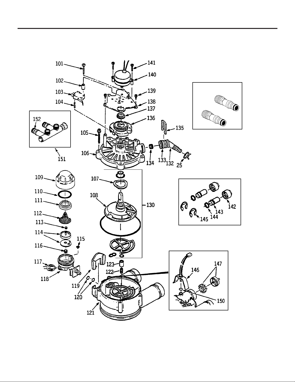
REF. NO. PART NO. PART DESCRIPTION
0025 WS18X10003 CLAMP HOSE 1
0101 WS02X10012 SCREW, #4 - 24 X 1-1/8″ 1
0102 WS02X10013 SPACER 1
0103 WS21X10003 SWITCH 1
0104 WS03X10009 PIN EXPANSION 1
0105 WS02X10014 SCREW, #10 - 14 X 2″ 5
0106 WS31X10006 COVER VALVE 1
0107 WS03X10010 WASHER WAVE 1
0108 WS26X10002 ROTOR & DISC 1
0109 WS19X10004 CAP 1
0110 WS03X10011 SEAL O-RING 1.1″ X 1.4″ 1
0111 WS19X10005 SUPPORT SCREEN 1
0112 WS03X10013 SCREEN 1
0113 WS22X10020 FLOW PLUG, .1 GPM 1
0114 WS08X10005 GASKET, NOZZLE/VENT 1
0115 WS03X10015 CONE SCREEN 1
0116 WS22X10021 PLUG, FILL FLOW, .3 GPM 1
0117 WS03X10017 NUT FERRULE 1
0118 WS15X10009 NOZZLE/VENTURI ASM. 1
0119 WS03X10018 RETAINER 1
0120 WS03X10019 SEAL O-RING 1/4″ X 3/8″ 2
0121 WS15X10010 BODY VALVE 1
0122 WS03X10020 SPRING 1
0123 WS22X10022 PLUG, DRAIN SALT 1
0130 WS35X10005 SEAL KIT 1
0132 WS22X10023 ADAPTER DRAIN HOSE 1
0133 WS03X10021 O-RING 5/8″ X 13/16″ 1
0134 WS03X10022 PLUG FLOW, RINSE CONTROL 1
0135 WS03X10023 CLIP 1
0136 WS26X10003 CAM & GEAR 1
0137 WS26X10004 BEARING 1
0138 WS26X10005 PLATE MOTOR 1
0139 WS02X10015 SCREW, #6 - 20 X 3/8″ 2
0140 WS26X10006 MOTOR ASM. 1
0141 WS02X10016 SCREW, #6 - 20 X 7/8″ 2
0142 WS60X10001 NUT INSTALLATION 2
0143 WS60X10002 TUBE INSTALLATION 2
0144 WS60X10003 WASHER 2
0145 WS60X10004 CLIP 2
0146 WS28X10005 HOUSING SENSOR 1
0147 WS19X10006 TURBINE & SUPPORT ASM. 1
0150 WS03X10024 SEAL, O-RING 1
0151 WS15X10012 VALVE BYPASS ASM. 1
0152 WS03X10025 SEAL, O-RING 2
0153 WS60X10006 ADAPTER 2
Page 25

What Is Not Covered:
For The Period Of: We Will Replace:
One Year Any part
of the Water Softening System which fails due to a defect in materials or workmanship.
From the date of the
During this
full one-year warranty,
GE will also provide,
free of charge,
all labor and in-home
original purchase
service to replace the defective part.
Three Years The electronic monitor,
if it fails due to a defect in materials or workmanship. During this
From the date of the three-year limited warranty,
you will be responsible for any labor or in-home service costs.
original purchase
Ten Years A replacement cabinet (brine tank) or resin tank,
if either fails due to a defect in materials or
From the date of the
workmanship. During this
ten-year limited warranty,
you will be responsible for any labor
original purchase
or in-home service costs.
25
GE Water Softening System Warranty.
(For Customers in the United States)
All warranty service provided by our Factory Service Centers, or an authorized Customer Care®technician.
For service, call 800-GE-CARES.
■ Service trips to your home to teach you how to use the
product.
■ Improper installation.
■ Failure of the product if it is abused, misused, or used for
other than the intended purpose or used commercially.
■ Filters, membranes or batteries.
■ Replacement of house fuses or resetting of circuit breakers.
■ Damage to the product caused by accident, fire, floods or
acts of God.
■ Incidental or consequential damage caused by possible
defects with this appliance.
This warranty is extended to the original purchaser and any succeeding owner for products purchased for home use
within the USA. In Alaska, the warranty excludes the cost of shipping or service calls to your home.
Some states do not allow the exclusion or limitation of incidental or consequential damages. This warranty gives you
specific legal rights, and you may also have other rights which vary from state to state. To know what your legal rights
are, consult your local or state consumer affairs office or your state’s Attorney General.
Warrantor: General Electric Company. Louisville, KY 40225
Page 26

For The Period Of: We Will Replace:
One Year Any part
of the Water Softening System which fails due to a defect in materials or workmanship.
From the date of the
During this
full one-year warranty,
GE will also provide,
free of charge,
all labor and in-home
original purchase
service to replace the defective part.
Three Years The electronic monitor,
if it fails due to a defect in materials or workmanship. During this
From the date of the three-year limited warranty,
you will be responsible for any labor or in-home service costs.
original purchase
Ten Years A replacement cabinet (brine tank) or resin tank,
if either fails due to a defect in materials or
From the date of the
workmanship. During this
ten-year limited warranty,
you will be responsible for any labor
original purchase
or in-home service costs.
26
What Is Not Covered:
■ Service trips to your home to teach you how to use the
product.
■ Improper installation.
If you have an installation problem, contact your dealer
or installer. You
are responsible for providing adequate
electrical, exhausting and other connecting facilities.
■
Replacement of house fuses or resetting
of circuit
breakers.
■ Failure of the product if it is misused, or used for other
than the intended purpose or used commercially.
■
Damage to product caused by accident,
fire, floods or acts
of God.
WARRANTOR IS NOT RESPONSIBLE FOR CONSEQUENTIAL DAMAGES.
Warrantor: CAMCO INC.
GE Water Softening System Warranty.
(For Customers in Canada)
All warranty service provided by our Factory Service Centers or an authorized technician.
For service, call toll free 1-866-777-7627.
Page 27

Sécurité
Installation adéquate . . . . . . . . . .29
Directives d’installation
Branchement de la conduite
de vidange . . . . . . . . . . . . . . . .33–34
Déballage et inspection . . . . . . .30
Directives d’installation . . . . .30–32
Directives d’installation
étape par étape . . . . . . . . . . . .33–37
Outillage et matériel requis pour
l’installation . . . . . . . . . . . . . . . . . .31
Planification et localisation . . . . .31
Programmation de la minuterie
. .35
Recommandations
importantes pour
l’installation . . . . . . . . . . . . . . . . . .30
Sanitization . . . . . . . . . . . . . . . . . .36
Spécifications et dimensions . . . .37
Instructions d’utilisation, conseils
Caractéristiques de la
minuterie du panneau
de commande . . . . . . . . . . . . . . . .40
Élimination d’un pont de sel . . .39
Nettoyage de l’ensemble
gicleur et venturi . . . . . . . . . . . . . .39
Service . . . . . . . . . . . . . . . . . . . . . .38
Système adoucisseur d’eau . .38–39
Système de régénération . . . .41, 42
Entretien et nettoyage
Élimination du fer . . . . . . . . . . . .43
Niveau de l’entreposage du sel
et remplissage . . . . . . . . . . . . . . . .43
Conseils de dépannage . . . .44–46
Service aux consommateurs
Garantie . . . . . . . . . . . . . . . . . . . . .51
Liste des pièces/catalogue . .47–50
Numéros de téléphone
importants . . . . . . . . . . . . . . . . . . .52
La section Française.
27
Page 28

28
À CONSERVER SOIGNEUSEMENT
Transcrivez les numéros de modèle et de série ici.
No
No
Vous les trouverez sur l’attache du réservoir.
Agrafez le reçu de vente ou le chèque annulé ici.
Pour obtenir le service sous garantie, il est nécessaire de disposer de la preuve de la date d’achat.
Vous y trouverez de nombreux conseils pour l’utilisation et l’entretien de votre adoucisseur d’eau.
Ces quelques mesures préventives vous permettront d’économiser du temps et de l’argent pour
la durée de vie de l’appareil. Nous avons inclus une cassette vidéo avec l’appareil laquelle comporte
des instructions importantes pour l’utilisation et l’entretien.
LISEZ VOTRE MANUEL
SI VOUS AVEZ BESOIN DE SERVICE
Vous trouverez des solutions aux problèmes courants que vous pourriez rencontrer dans la section
Avant
d’appeler un réparateur
. Et, en consultant d’abord nos
Conseils de dépannage
, vous pourriez peut-être éviter
de faire appel à un réparateur.
Si vous avez besoin de service, vous savez que vous n’avez qu’à nous téléphoner. Vous trouverez à la fin
de ce présent manuel les numéros sans frais du service à la clientèle.
OU
Visitez notre site Web au
www.geappliances.com
IMPORTANT!
Remplissez la carte d’enregistrement du produit.
Il y a deux manières faciles d’enregistrer votre appareil!
■ Par l’Internet en saisissant l’adresse www.geappliances.com
■ En remplissant et en expédiant la carte d’enregistrement du produit ci-incluse
Vous et GE, un partenariat de service.
Page 29

VEUILLEZ LIRE ET SUIVRE ATTENTIVEMENT CES MESURES DE SÉCURITÉ.
CONSERVEZ CES DIRECTIVES
29
AVERTISSEMENT!
Pour votre sécurité, suivez les directives fournies dans le présent
manuel afin de minimiser les risques de chocs électriques, des dégâts
matériels et de blessures graves.
SÉCURITÉ
■
Vérifiez et respectez les codes de sécurité locaux et ceux
de l’état où vous résidez. Vous devez suivre les lignes de
conduite suivantes.
■
Faites attention lors de l’utilisation de l’appareil
adoucisseur d’eau. Ne le placez pas la tête en bas, ne le
laissez pas tomber, ne le tirez pas ou ne le faites pas
passer sur des aspérités pointues.
■
Pour les adoucisseurs utilisant le chlorure de sodium
(sel) pour la régénération, ajoutez du sodium à l’eau.
Les personnes soumises à des restrictions concernant
les diètes à base de sodium doivent considérer le
sodium complémentaire comme faisant partie de la
dose quotidienne qu’elles prennent. Il est possible de
remplacer le chlorure de sodium par du chlorure de
potassium dans votre l’adoucisseur.
■
L’adoucisseur d’eau fonctionne avec une alimentation
électrique de 24 volts sous 60 Hz seulement.
Assurez-
vous d’utiliser uniquement le transformateur ci-inclus.
■
Le transformateur doit être branché dans une prise
murale ordinaire de 120V (3 alveoles, mise à la terre).
■
N’utilisez que du sel adoucisseur d’eau propre avec une
pureté minimale de 99,5%. Nous recommandons le sel
NUGGET, PELLET ou du sel brut SOLAR.
N’utilisez pas
du sel à l’état solide, en blocs, granulé ou le sel servant à la
fabrication de crème glacée.
Ce type de sel contient des
saletés, des sédiments, du charbon et du cake qui
engendreront des problèmes d’entretien.
■
Gardez le couvercle de l’orifice du sel en place sur
l’adoucisseur excepté pour l’entretien de l’appareil ou si
ce dernier est en cours de remplissage avec du sel.
AVERTISSEMENT
:
N’utilisez pas
l’appareil si l’eau n’est pas pure sur le plan
microbiologique ou si sa qualité n’est pas éprouvée
sans qu’elle n’ait été désinfectée avant ou après
avoir été traitée par l’appareil.
UNE INSTALLATION ADÉQUATE
■
Installez ou entreposez l’appareil à l’abri de
températures inférieures au point de congélation, des
intempéries au autres types de temps. Le gel de l’eau
entraînera le bris de l’appareil. Ne pas tenter de traiter
de l’eau dont la température est supérieure à 100
degrés F.
■
N’installez pas
l’appareil dans une zone soumise
directement à la lumière du soleil. Une chaleur excessive
engendrée par le soleil peut entraîner des déformations
ou d’autres dommages aux composants non-métalliques.
■
Effectuez les mises à la masse conformément aux codes
et règlements en cours.
■
N’utilisez que de la
soudure et du flux
décapant sans
plomb pour toutes les soudures faites sous la base de
soudure tendre, telles que requises par les codes
fédéraux et ceux de l’état intéressé.
■
L’adoucisseur exige un débit minimum de trois
gallons/minute à l’orifice d’entrée. La pression
maximale autorisée est de 125psi. Si au cours de la
journée, la pression est supérieure à 80 psi, la pression
au cours de la nuit peut être supérieure à la valeur
maximale. Si nécessaire, utilisez une valve réductrice
de pression pour réduire le débit.
■
En présence de chlore dépassant la proportion
de 1 ppm, il est possible que les résines de l’adoucisseur
se dégradent. Si le chlore dépasse cette valeur, il est
possible que vous constatiez une durée de vie réduite des
résines. Dans un tel cas, vous pourriez envisager de faire
l’achat d’un système de filtrage de GE.
AVERTISSEMENT :
Débarrassez-vous de tout composant inutilisé
et du matériel d’emballage après l’installation
Les petits composants restant après l’installation
peuvent constituer un danger d’étouffement
après ingestion.
Avant d’utiliser votre adoucisseur, assurez-vous qu’il a été correctement installé, conformément aux
Directives d’installation.
MESURES DE SÉCURITÉ IMPORTANTES.
LISEZ D’ABORD TOUTES LES DIRECTIVES.
Page 30

Veuillez prendre connaissance du manuel au complet. Négliger de suivre toutes les consignes et règles
peut entraîner des blessures personnelles ou des dommages.
• Avant le début de l’installation, prendre connaissance de toutes les instructions correspondantes.
Ensuite, réunissez tout le nécessaire et l’outillage requis pour cette opération. Une installation
incorrecte annule la garantie.
• Prendre connaissance des codes locaux. L’installation doit être conforme à ces codes.
•
Dans l’état du Massachusetts, il y a lieu de respecter le code de plomberie 24 R CMR.
Veuillez consulter votre plombier qualifié
.
• Utilisez seulement la soudure et le flux décapant sans plomb pour tous les branchements effectués à
l’aide de soudures tendres comme prescrit par les codes fédéraux et ceux de l’état considéré.
• Branchez l’adoucisseur à la conduite d’alimentation d’eau
avanteten amont
du chauffe-eau.
NE FAITES
PAS PASSER DE L’EAU BOUILLANTE DANS L’ADOUCISSEUR.
La température de l’eau qui traverse l’appareil
doit être inférieure à 120 degrés F.
• Manipulez l’adoucisseur avec précaution. N’ inversez pas l’appareil, ne le laissez pas tomber, ne le tirez
pas ou ne l’installez pas sur des surfaces comportant des aspérités acérées.
• La pression maximale d’arrivée d’eau est de 125 psi. Si au cours de la journée la pression s’établit à 80
psi, elle peut dépasser le maximum toléré au cours de la nuit. Si nécessaire, utilisez une soupape de
réduction de pression (L’ajout d’un tel dispositif peut réduire le débit d’eau).
• L’adoucisseur ne fonctionne que sous une tension de 24 volts, 60Hz. Assurez-vous de bien utiliser le
transformateur inclus. Assurez-vous que le transformateur et la prise de courant soient à l’abri de
l’humidité.
• Référez-vous à la section
Où installer l’adoucisseur
pour de plus amples détails.
AVERTISSEMENT :
N’utilisez pas cet appareil avec de l’eau qui n’est pas microbiologiquement
sécuritaire ou de qualité inconnue sans que l’eau n’a pas été désinfectée avant ou après avoir
pénétré dans l’adoucisseur. Testez l’eau périodiquement pour vous assurer que l’appareil
fonctionne de manière satisfaisante.
Les petits composants accompagnant l’appareil qui n’ont pas été utilisés au montage peuvent
présenter des dangers d’étouffement. Débarrassez-vous en.
30
Directives d’installation.
ATTENTION :
Il est nécessaire de posséder une certaine expérience en plomberie pour effectuer
l’installation. Si vous n’êtes pas certain en ce qui concerne une ou plusieurs étapes d’installation de
l’appareil, veuillez consulter un plombier professionnel.
Déballage et inspection
L’appareil adoucisseur d’eau est expédié dans une boîte principale. Il est complètement assemblé en
usine sauf pour les éléments nécessaires à l’installation.
Assurez-vous de vérifier si l’appareil n’a pas été endommagé au cours de l’expédition et si tous les
composants sont présents. Veuillez également noter si la boîte ayant servi pour l’expédition n’a pas été
endommagée. Contactez la Compagnie ayant effectué le transport en cas de dommage ou de perte. Le
fabricant n’est pas responsable en cas de dommages au cours du transport.
Les petites pièces requises pour l’installation de l’adoucisseur sont emballées sur un carton sous
Cellophane. Pour éviter leur perte, gardez les dans leur emballage jusqu’au moment où elles seront
requises.
Recommandations importantes pour l’installation
Page 31

• Les raccords pour l’entrée et la sortie de l’eau, lesquels sont inclus avec l’adoucisseur sont des raccords
de cuivre brasable de 3⁄4 po. Afin de maintenir un débit intégral au robinet, il est recommandé
d’utiliser des tuyaux de 1 po. de diamètre pour les raccords d’entrée et de sortie. Gardez les mêmes
dimensions ou des dimensions supérieures pour les tuyaux d’alimentation d’eau à l’entrée et à la sortie
d’eau de l’adoucisseur.
• Pour installer l’adoucisseur, utilisez le robinet de dérivation inclus. Le robinet de dérivation permet
d’arrêter l’eau arrivant à l’adoucisseur aux fins d’entretien tout en maintenant celle-ci dans les tuyaux
de la résidence. Les raccords d’entrée et de sortie mentionnés ci-dessus permet le branchement au
robinet de dérivation au moyen des écrous et rondelles qui sont inclus.
• Utilisez les tuyaux et raccords en cuivre, laiton ou métal galvanisé. Certains codes permettent
l’utilisation des tuyaux en plastique PVC.
• S’il est nécessaire de disposer d’un tuyau d’évacuation complémentaire pour le robinet de vidange des
réservoirs de sel, vous pouvez le commander au service des pièces de GE en téléphonant au numéro
800.626.2002.
•
S’il est nécessaire de disposer d’un tuyau d’évacuation rigide pour rester conforme aux codes régissant
le plombage, vous pouvez acheter les pièces requises (Fig. 4A) pour brancher le tuyau de cuivre de
1
⁄2 po. de diamètre ou un tuyau d’évacuation en plastique.
• Il est nécessaire d’avoir du sel d’adoucissement d’eau sous forme de pastilles ou de pépites pour
remplir le réservoir de solution saline. Voir
l’étape 8
dans les
Directives d’installation Étape par Étape
.
31
• Positionnez l’adoucisseur le plus près possible d’un égout d’évacuation ou de tout autre point
d’évacuation ou tuyau de refoulement acceptable.
• Il est recommandé de laisser les robinets extérieurs débiter l’eau dure (non traitée) afin de ménager
l’eau traitée et le sel.
•
N’installez pas l’adoucisseur à un endroit où il pourrait geler.
Tout dommage causé par le gel n’est pas
couvert par la garantie.
• N’installez pas l’adoucisseur à un endroit où il interdirait l’accès au chauffe-eau ou au robinet de
fermeture de l’arrivée d’eau.
• Positionnez l’adoucisseur de telle façon à ce que les dommages causés par une fuite éventuelle d’eau
soient minimisés. Le fabricant n’effectuera pas les réparations et ne dédommagera pas le propriétaire
en cas de dommages causés par l’eau.
• Il est nécessaire de disposer d’une prise de 120 volts pour y brancher le transformateur inclus. La
longueur du fil d’alimentation de l’appareil est de 10 pi. Si la prise de courant est éloignée (100 pi ou
moins), utilisez un fil de calibre 18 pour le branchement.
Assurez-vous que la prise de courant et le
transformateur sont à l’intérieur du bâtiment afin de les protéger contre l’humidité.
Assurez-vous que la prise
est hors-tension afin de prévenir tout arrêt accidentel.
• Si l’appareil est installé à l’extérieur, prenez toutes les dispositions nécessaires pour vous assurer que
l’adoucisseur, les conduites servant à l’installation, le câblage, etc. sont protégés contre les éléments
(soleil, pluie, vent, chaleur, froid), contamination, vandalisme, etc. comme si l’appareil avait été
installé à l’intérieur.
•
Assurez-vous que l’adoucisseur ne soit pas exposé directement aux rayons du soleil.
La chaleur du soleil
peut déformer les parties non-métallques et endommager les composants électroniques.
Où installer l’adoucisseur
Outillage et matériel requis pour l’installation
Initialement, vous devez décider comment vous allez brancher les tuyaux d’entrée et de sortie d’eau à
l’adoucisseur. Examinez la conduite principale d’arrivée d’eau dans l’habitation là où vous allez
brancher l’appareil. Cette conduite est-elle en cuivre, en plastique ou en métal galvanisé avec filetage?
Quelle est la dimension de la conduite?
AVERTISSEMENT :
N’utilisez que de la soudure et du flux décapant sans plomb pour éviter tout
empoisonnement.
Référez-vous à la fig. 1,
Illustration d’une installation type.
Utilisé comme guide lors de votre installation
particulière.
Assurez-vous de diriger l’eau d’arrivée dure (non traitée) dans le raccord de la soupape contrôlant
l’admission d’eau à l’adoucisseur.
La soupape porte les indications IN(entrée) et
OUT
(sortie). Voyez
l’illustration en page 32.
Planifiez comment vous allez installer l’adoucisseur
Page 32

Fig. 1
Directives d’installation.
Illustration d’une installation type
Illustration de l’installation optionnelle des robinets de dérivation à 3 voies
Fig. 2
32
Les adaptateurs pour cette installation ne sont pas fournis avec l’adoucisseur.
Pour commander ces adaptateurs, appelez le service des pièces de GE au numéro 800-626-2000 et demandez la
pièce portant le no WS60X10006.
Eau traitée
Eau dure (non
traitée) vers
robinets
extérieurs
CONDUITE D’EAU PRINCIPALE
Eau dure (non traitée)
Écrou pour l’installation (2)
Tube en cuivre, 3/4 po (2)
Rondelle (2)
Robinet de dérivation
• Tirer pour le service en eau traitée
• Pousser pour dérivation
NOTE :
Le filetage des adaptateurs
utilisés pour l’installation sont pour
tuyaux mâles de 1 po de diamètre.
Si des tuyaux de 1 po de diamètre
sont requis, ne pas utiliser les
tuyaux et écrous en cuivre inclus.
Achetez un adaptateur pour tuyau
de 1 po avec filetage femelle et
raccorder directement aux filetages
de 1 po des adaptateurs utilisés
pour l’installation.
ADMISSION
Contenant pour
solution saline
NOTE :
Voir
la section
Branchements
au tuyau de
vidange
.
L'ENTRÉE
DU SEL
Orifice de
remplissage de
solution saline,
couvercle retiré
Transformateur de 24 volts
prise de courant de 120 volts
Eau dure
(non traitée)
Eau traitée
En provenance de
l’orifiice de sortie
de l’adoucisseur
Vers l’orifice d’entrée
de l’adoucisseur
CROISEMENT
Utilisez si l’alimentation d’eau
provient du côté gauche.
Incluez une dérivation simple
ou à 3 soupapes.
Eau dure
(non traitée)
Eau traitée
En provenance de
l’orifice de sortie
de l’adoucisseur
Vers l’orifice d’entrée
de l’adoucisseur
CROISEMENT
Utilisez si l’alimentation d’eau
provient du côté gauche.
Incluez une dérivation simple
ou à 3 soupapes.
CONDUITE D’EAU
PRINCIPALE
Eau traitée
Eau dure (non traitée)
Tube en cuivre, diamètre 3/4 po
Rondelle (2)
Adaptateur pour l’installation (2) (voir ci-dessus)
ADMISSION
Transformateur de 24 volts
Prise de 120 volts
Robinet de dérivation
Eau dure (non traitée)
vers robinets
extérieurs
Robinet d’entrée
Robinet de sortie
Écrou (2)
Circuit de dérivation à 3 robinets
Pour alimentation en eau traitée :
• Ouvrez les robinets d’entrée et de sortie
• Fermez le robinet de dérivation
Pour dérivation de l’eau dure (non traitée) :
• Fermez les robinets d’entrée et de sortie
• Ouvrez le robinet de dérivation
Raccord (2) (non fournis)
NOTE :
Le filetage des adaptateurs utilisés pour l’installation sont pour tuyaux mâles de 1 po de diamètre. Si des
tuyaux de 1 po de diamètre sont requis, ne pas utiliser les tuyaux et écrous en cuivre inclus. Achetez un adaptateur
pour tuyau de 1 po avec filetage femelle et raccorder directement aux filetages de 1 po des adaptateurs utilisés pour
l’installation.
Page 33

Directives d’installation étape par étape.
• Arrêtez l’alimentation en gaz ou en électrique du chauffe-eau dans le cas où ce dernier soit vidé
lorsque les conduites sont asséchées.
• Arrêtez l’alimentation en eau aux conduites devant être coupées et videz les conduites d’eau de
la résidence.
• Ouvrez les robinets d’eau chaude et froide.
1. INSTALLEZ LE CLAPET DE DÉRIVATION
• Enlever le bouchon en plastique ayant servi pour l’expédition de l’appareil ainsi que le fil de le
logement de sortie du clapet.
• Poussez sur le robinet de dérivation (lubrifiez les joints toriques avec la graisse à base de
silicone) dans les deux orifices du clapet tel qu’indiqué à la figure 3A.
• Mettez en position les deux grandes attaches en plastique de haut en bas, tel qu’indiqué à la
figure 3A et 3B. Assurez-vous qu’ils soient bien en place. Tirez sur le clapet de dérivation pour
vous assurer qu’il est fermement maintenu en place.
2. PLACER L’ENSEMBLE DE L’ADOUCISSEUR EN POSITION D’INSTALLATION :
• Assurez-vous que la surface sur laquelle l’appareil sera installé est bien horizontale et sans
aspérités. Des objets pointus situés sous le réservoir peuvent percer celui-ci. Si nécessaire, placer
le réservoir sur une planche de contre-plaqué dont l’épaisseur minimale est de 3/4 po. Puis
placez des cales sous la planche, le cas échéant, pour que l’adoucisseur soit en position
horizontale.
3. FAIRE LE RACCORDEMENT DES TUYAUX D’ARRIVÉE ET DE SORTIE D’EAU DE
L’ADOUCISSEUR :
ATTENTION : Respectez toutes les consignes de mise en garde suivantes lors du
branchement des conduites aux orifices d’entrée et de sortie. Voir les figures 1 ou 2.
• ASSUREZ-VOUS QUE L’EAU DURE (NON TRAITÉE) ARRIVANT
EST DIRIGÉE SUR L’ORIFICE D’ENTRÉE DU CLAPET DE L’ADOUCISSEUR. Si le débit
d’eau provient du côté gauche, utilisez un croisement illustré à la figure 1.
• Si l’installation est faite par soudage de composants en cuivre, faire le soudage tendre avant de
raccorder les tuyaux au clapet de dérivation. La chaleur du chalumeau endommagerait les
composants en plastique.
• Lors de la rotation des raccords de tuyaux dans les raccords en plastique, faites attention de ne
pas foirer le filetage.
• Utilisez un composé sur tous les filetages externes des tuyaux.
• Faire un support pour la tuyauterie d’arrivée et de sortie d’eau (supports à tuyaux) afin
d’alléger le poids imposé aux raccords de robinets.
4. RACCORDEZ ET FAITES FONCTIONNER LE TUYAU DE VIDANGE :
• Utilisez le tuyau de vidange fourni (inclus et dont la longueur est de 20 pi.) et le brancher au
raccord du robinet de vidange. Afin d’empêcher la pression de l’eau de débrancher le tuyau,
utilisez une attache pour le maintenir en place.
• Localisez l’autre extrémité du tuyau et placez-le à un orifice de vidange approprié (orifice de
vidange du plancher, réservoir, bac utilisé pour la vidange de l’eau de laveuse, etc.) qui aboutit
à l’égout. Vérifiez quels sont les codes locaux et respectez-les.
IMPORTANT : Si une longueur supplémentaire de tuyau de vidange est nécessaire, vous pouvez
commander le tuyau au service des pièces GE au no 800-626-2002. L’adoucisseur ne peut
fonctionner si l’eau ne peut être évacuée du tuyau au cours des régénérations.
• Attachez ou fixez le tuyau en place à l’aide d’un fil au point de vidange. La haute pression de
l’eau entraînera le retrait et des cycles de rinçage rapides au cours des régénérations. De plus,
ménagez un espace minimum de 1-1/2 po. entre l’extrémité du tuyau et du point de vidange.
Un tel espace empêche l’eau d’égout d’être siphonnée à l’intérieur de l’adoucisseur en cas de
refoulement de l’égout.
• S’il est nécessaire de soulever le tuyau de vidange pour atteindre le point de vidange, ne le
soulevez pas à une hauteur supérieure à 8 pi. par rapport au plancher. Le fait de le faire peut
causer une contre-pression risquant de réduire l’aspiration de la solution saline au cours des
régénérations.
Fig. 3A
Fig. 3B
Fig. 3C
Fig. 4
NOTE : Assurez-vous que la turbine
et son support sont fermement
montés dans le logement de sortie
du clapet. Soufflez dans l’orifice du
clapet et notez si la turbine tourne
librement.
Raccord
du
tuyau
de
vidange
sur le
robinet
Tuyau de
vidange
VIDANGE AU SOL
Turbine
Logement de sortie
Arbre de turbine
et palier
ENTRÉE
SORTIE
Tourner le clapet de
dérivation sur 180
degrés pour le
brancher à la
conduite se trouvant
au niveau du sol
Corps du clapet,
entrée ou sortie
Clapet de dérivation
(poussez
complètement à
l’intérieur)
Attache
VUE À
L’EXTRÉMITÉ
Attache
Sortie
Entrée
Le joint torique n’est
placé que dans la
rainure extérieure.
L’attache se place dans
la rainure intérieure
(voir ci-dessous).
Clapet de dérivation
NOTE :
Le filetage des adaptateurs
utilisés pour le clapet de dérivation
sont pour tuyaux mâles de 1 po de
diamètre. Si des tuyaux de 1 po de
diamètre sont requis, ne pas utiliser
des tuyaux et écrous en cuivre inclus.
Achetez un adaptateur pour tuyau de
1 po avec filetage femelle et
raccorder directement aux filetages
de 1 po.
VUE LATÉRALE
Attachez le
tuyau ou fixez-le
par un fil
TUYAU DE REFOULEMENT
BAC DE VIDANGE
POUR LAVEUSE
RÉSERVOIR
33
Attache
Espace de 1
1
⁄2 po.
Espace de 11⁄2 po
.
Espace de
11⁄2 po
.
Espace de
11⁄2 po
.
Page 34

Directives d’installation étape par étape.
34
4A. BRANCHEMENT D’UN TUYAU DE VIDANGE RIGIDE
• Pour adapter un tuyau de vidange en cuivre à l’adoucisseur, utilisez une scie à métaux pour couper l’extrémité
barbelée du raccord de vidange comme illustré à la figure 4A. Faire tourner le raccord de vidange de telle
manière que la lame de la scie soit éloignée du logement du clapet pour prévenir tout dommage à celui-ci.
Achetez un raccord à compression (filetage femelle de 1/4 po. x 1/2 po. pour le tube O.D) et la tuyauterie
requise de votre quincaillier.
5. INSTALLATION DES RACCORDS DE DÉBORDEMENT DU RÉSERVOIR DE SOLUTION SALINE ET
LA TUYAUTERIE
• Insérez l’oeillet en caoutchouc dans l’orifice de 3/4 po. de diamètre sur la paroi latérale du réservoir comme
indiqué à la figure 5.
• Poussez l’extrémité du coude de l’adaptateur du tuyau dans l’oeillet comme indiqué à la figure 5.
• Fixez une longueur de tuyau (utilisez le reste de tuyau de l’étape 4) au coude de l’adaptateur du tuyau. Utilisez
une attache de tuyau pour maintenir ce dernier en place.
• Placez l’autre extrémité du tuyau au point de vidange. N’ÉLEVEZ PAS ce tuyau à une hauteur supérieure au
coude sur le réservoir de solution saline.
IMPORTANT : NE FIXEZ PAS LE TUYAU DE DÉBORDEMENT AU TUYAU DE VIDANGE.
NOTE : Le tuyau de vidange ne sert que pour des besoins de sécurité. Si le réservoir de solution saline se remplit
excessivement d’eau, l’excédent sera dirigé sur l’orifice de vidange.
6. INSTALLATION D’ATTACHES DE MISE À LA MASSE ET CÂBLAGE
DANGER : Le fait de ne pas mettre à la masse le fil servant à cet effet peut causer des chocs électriques.
• Si la tuyauterie est en métal, et afin de maintenir une continuité de mise à la masse électriquepour la
tuyauterie d’eau froide, montez les attaches de mise à la masse incluses à l’appareil comme indiqué à la
figure 6. Assurez-vous que les tuyaux se trouvant sous les attaches sont propres afin d’assurer un bon
contact électrique.
7. RINÇAGE DES TUYAUX, ÉLIMINATION DE L’AIR DE L’ADOUCISSEUR ET ESSAI DE
L’INSTALLATION POUR DÉTECTER LES FUITES D’EAU :
ATTENTION : Pour éviter tout dommage causé par l’eau ou la pression de l’air pouvant affecter les
composants internes de l’adoucisseur, assurez-vous de suivre les étapes suivantes dans l’ordre exact.
A. Ouvrez complètement 2 robinets d’eau traitée froide à proximité de l’adoucisseur.
B. Placez le robinet de dérivation sur la position « bypass » (dérivation) en poussant l’axe vers l’intérieur.
C. Ouvrez complètement le robinet principal d’alimentation en eau de la résidence. Notez s’il existe un débit
continu des deux robinets qui ont été ouverts à l’étape A ci-dessus.
D. Placez le robinet de dérivation sur la position « service » (service) EXACTEMENT comme suit. GARDER
LES ROBINETS D’ALIMENTATION EN EAU TRAITÉE SUR LA POSITION OUVERTE.
Tirez LENTEMENT ou faites glisser la tige du robinet (vers l’extérieur) vers la position « service » (service)
en faisant plusieurs pauses afin de permettre à l’adoucisseur d’être lentement mis sous pression.
E. Après environ 3 minutes, ouvrez un robinet d’eau HOT (bouillante) pendant 1 minute ou jusqu’à ce que l’air
ait été évacué puis le fermer. NOTE : Si l’eau paraît trouble ou si le goût est salé, continuez pendant plusieurs
minutes ou jusqu’à ce que l’eau devienne claire.
F. Fermez tous les robinets.
G. Vérifiez les travaux de plomberie que vous avez effectués pour détecter toute fuite. Réparez celles-ci
immédiatement le cas échéant et assurez-vous de respecter les notes de mise en garde précédentes.
H. Mettez en marche l’alimentation en gaz ou en électricité pour le chauffe-eau. Allumez la flamme veilleuse le
cas échéant.
Fig. 4A
Fig. 5
Fig. 6
Attache (2)
Fil de
mise à la
masse
En provenance du
robinet de sortie
Vers le robinet
d’entrée
À l’égout
Tuyau de vidange
pour débordement
Attache du
tuyau
Oeillet en
caoutchouc
Attache
Filetage NPT 1/4 po
Extrémité
barbelée
1/2 po O.D.
Tube en cuivre
(non fourni)
Coupez l’extrémité
barbelée du raccord
de vidange
Raccord de compression
1/4 po tube NPT x 1/2 po
OD (non fourni)
Ne pas brancher sur le
tuyau de vidange.
Adaptateur du
tuyau
8. AJOUT DE L’EAU ET DU SEL AU RÉSERVOIR DE SOLUTION SALINE
• Levez le couvercle du réservoir solution saline. Ajoutez environ 3 gallons d’eau dans le réservoir. N’en ajoutez pas dans le contenant pour solution saline.
• Remplir le réservoir avec le produit NUGGET (pépites), PELLET (pastilles) ou avec le sel brut pour adoucisseur SOLAR dont la pureté doit être égale ou
supérieure à 99,5%. N’utilisez pas du sel en roches, en blocs, granulé ou le sel servant à la confection de crème glacée ou encore du sel contenant des additifs
servant à éliminer le fer, ( à l’exception du sel de marque Diamond Crystal® Red•Out®). La capacité d’entreposage du sel est d’environ 200 lbs. Gardez le
couvercle de l’orifice pour le sel en place sur l’adoucisseur sauf au cours de l’entretien de l’appareil ou lorsque le remplissage du sel a lieu.
NOTE : Si l’adoucisseur est installé dans un sous-sol humide ou tout autre endroit également humide, il est préférable de remplir le réservoir avec moins de sel
et plus fréquemment. Une quantité de 80 à 100 lbs de sel durera plusieurs mois en fonction de la dureté de l’eau, le nombre de personnes dans la famille et du
modèle d’adoucisseur d’eau.
9. BRANCHEMENT À LA SOURCE D’ALIMENTATION ÉLECTRIQUE
• Si le câble du transformateur n’est pas visible à l’arrière de l’appareil, retirez le couvercle. NE TIREZ PAS SUR LE CÂBLE OU NE LE DÉBRANCHEZ PAS.
Localisez le long fil comportant des connecteurs en U à l’une des extrémités. Faites passer le fil au travers du logement du panneau de commande. Remettez le
couvercle en place.
• Fixez les connecteurs en U aux 2 vis du transformateur et serrez celles-ci. Ensuite, branchez le transformateur dans la prise de courant.
• L’adoucisseur fonctionne sous une tension de 24 volts 60 Hz. Le transformateur inclus à l’appareil réduit le courant de 120 volts CA standard à 24 volts. Ne branchez le
transformateur que dans une prise de 120 volts. Assurez-vous que la prise est en permanence sous tension de façon à ce que l’alimentation électrique ne soit pas coupée par
erreur.
10. PROGRAMMATION DE LA MINUTERIE :
• Référez-vous à la section Programmation de la minuterie.
Page 35

35
Programmation de la minuterie
Affichage du temps :
Lorsque le transformateur est branché dans une prise électrique, le message 12:00AM, SUnday clignote dans la
fenêtre d’affichage. Programmez l’heure du jour et le jour de la semaine comme suit :
A.
Programmez l’heure du jour :
Appuyez sur le bouton
TIME/DAY
une fois et l’affichage de l’heure commence à clignoter.
Appuyez sur le bouton
SET/CLEAR
jusqu’à ce que l’heure actuelle soit affichée dans la fenêtre.
Assurez-vous que AMs’affiche pour les heures du matin ou PMpour les heures d’après midi
ou du soir.
NOTE :
Appuyez sur le bouton
SET/CLEAR
et le relâcher rapidement pour déplacer l’affichage de 1
heure à la fois afin d’atteindre l’heure correcte. Ou maintenir le bouton
SET/CLEAR
enfoncé pour
déplacer l’affichage vers l’avant à raison de 2 heures chaque seconde jusqu’à l’heure correcte.
Appuyez sur le bouton
TIME/DAY
une fois afin de stabiliser l’affichage de l’heure. Les minutes
commencent à clignoter.
Répétez
l’étape A. 2
pour afficher les minutes correctes.
Appuyez sur le bouton
TIME/DAY
à nouveau afin de stabiliser l’affichage des minutes (day va
clignoter). La figure 7 montre la minuterie programmée à 3:30 PM.
B.
Programmez le jour de semaine actuel :
Appuyez sur le bouton
SET/CLEAR
pour régler le jour actuel de la semaine dans la fenêtre
d’affichage.
NOTE :
Appuyez sur le bouton
SET/CLEAR
et le relâcher rapidement pour déplacer l’affichage du jour
à raison de 1 jour chaque fois. Ou maintenir le bouton
SET/CLEAR
enfoncé pour déplacer l’affichage
du jour vers l’avant à raison de 2 jours par seconde.
Appuyez sur le bouton
TIME/DAY
une fois de plus pour stabiliser l’affichage au complet. La figure 7
montre la minuterie programmée à
TUesday
.
Aucun autre réglage n’est requis
après l’installation de l’adoucisseur d’eau. L’appareil a été programmé
en usine pour assurer la régénération tous les lundis, mercredis et samedis (début à 2:00 AM). La majorité
des familles disposent donc de suffisamment d’eau traitée pour leurs besoins. Cependant, si vous
souhaitez que l’appareil régénère à des heures différentes à des jours différents ou pour fonctionner avec
une efficacité optimale, référez-vous à la section
Au sujet du système adoucisseur d’eau
.
2
1
4
3
2
1
Référez-vous à la section
Utilisation
pour d’autres commandes et
fonctions de la minuterie.
Fig. 7
EXEMPLE : Ce schéma montre
l’heure actuelle du jour à 3:30 PM.
Le jour actuel est TUesday (mardi).
Fenêtre
d’affichage
Page 36

Directives d’installation étape par étape.
36
Méthodes de sanitization
Toutes les précautions ont été prises en usine pour
s’assurer que l’adoucisseur est propre et conforme aux
conditions d’hygiène. Les matériaux utilisés pour la
fabrication de l’appareil n’infecteront ni ne
contamineront votre eau et ne causeront pas de
formation de bactéries ou leur développement.
Cependant, il est possible que des bactéries pénètrent
dans l’adoucisseur au cours de l’expédition,
l’entreposage, l’installation et l’utilisation. C’est pour
cette raison que nous suggérons de procéder à une
sanitization lors de l’installation.
NOTE : La sanitization est recommandée par la Water
Quality Association (association chargée de faire
respecter la qualité de l’eau) pour assurer la désinfection.
Assurez-vous d’accomplir toutes les étapes de
l’installation, la programmation de la minuterie
incluse.
Retirez le couvercle du contenant de solution
saline (voir la figure 8) et versez environ 3/4 onces
d’Eau de Javel domestique concentré à 5,25%
(Clorox, Linco, BoPeep, White Sail, Eagle, etc.)
dans le
contenant
.
Appuyez sur le bouton
TOUCH/HOLD
(Appuyez/Maintenez) et maintenez-le enfoncé
pendant 3 secondes pour déclencher une
recharge. Cette première recharge accomplit
plusieurs fonctions : remplissage du contenant de
solution saline jusqu’au niveau d’eau requis, purge
de l’air du réservoir de résine, préparation du
“lit”de résine pour qu’il soit prêt au service. Voir
la section
Recharge
.
Si après avoir suivi cette procédure, l’eau
provenant des robinets de l’habitation a un goût
salé ou est légèrement colorée, ceci est causé par la
matière préservative provenant du réservoir de
résine. Ouvrez les robinets d’eau froide et laissez
couler l’eau pendant quelques minutes ou jusqu’à
ce que l’eau soit claire.
NOTE : La recharge demande environ 2 heures.
4
3
2
1
Fig. 8
Couvercle de l’orifice
de remplissage de sel
retiré
Tuyau
Contenant
pour
solution
saline
Couvercle du
contenant de
solution
saline
(Retirez et
ajoutez
environ 3/4
onces d’Eau
de Javel)
Eau environ
3 gallons
NOTE :
Une fois le processus de régénération pour
sanitization terminé, votre eau FROIDE a été
complètement traitée. Cependant, votre chauffe-eau
est rempli d’eau dure (non traitée) et au fur et à
mesure que l’eau est consommée, celle-ci est
remplacée par de l’eau traitée et l’eau bouillante
ainsi que le mélange eau bouillante/eau froide sera
composé complètement d’eau traitée. Si vous
souhaitez immédiatement avoir de l’eau traitée,
videz le chauffe-eau jusqu’à ce que l’eau soit froide
après le processus de régénération.
AVERTISSEMENT :
Si vous videz le chauffe-eau,
faites très attention car l’eau bouillante peut
causer des brûlures. Éteindre le chauffe-eau
avant de le vider.
Page 37

37
Spécifications/Dimensions
(Voyez le décalcomanie des
capacités situé
Capacité nominale* sur l’adoucisseur)
Quantité de résine de haute capacité (lbs/pi.cu) 31,2/,6
Dimension nominale du réservoir de résine (diamètre en pouces x hauteur)
8 x 40
Débit de service (gpm) 7,5
Dureté maximale de l’eau d’alimentation (gpg) 50
Fer maximal contenu dans l’eau traitée (ppm)** 3
Limites de pression d’eau (min.max.psi) 20-125
Chute de pression à la valeur nominale du débit de service (psig)
15
Température maximale de l’eau (degrés F.) 120
Débit minimal de l’eau d’alimentation (gpm) 3
Débit du cycle de régénération (gpm)
Remplissage (débit au réservoir de solution saline) ,3
Lavage avec solution saline ,19
Rinçage de la solution saline ,12
Refoulement 1,8
Rinçage rapide 1,8
Le système est conforme aux normes WQA S-100 pour les capacités spécifiques tels que vérifiées et
confirmées par les données faisant suite aux essais.
* Les essais ont été faits en utilisant le chlorure de sodium pour pastilles comme agent de régénération.
** La quantité de fer éliminé peut varier avec les conditions existantes. Cette élimination est améliorée
en utilisant les produits Diamond Crystal® Red•Out® ou Super Iron Out®. Voir la section
Élimination du
fer contenu dans l’eau.
}
(Débit vers
l’orifice de
vidange)
111⁄2 po
3
3
⁄8 po
SOR
TIE
ENTR
ÉE
ENTRÉE-SORTIE
483/4 po
411⁄4 po
181⁄4 po
401⁄2 po
Page 38

Service
Lorsque le système adoucisseur d’eau fournit de l’eau traitée, il est appelé « Service ».
Dans cette fonction, l’eau dure (non traitée) en provenance de la conduite principale de
la résidence s’écoule dans le système adoucisseur d’eau. À l’intérieur du réservoir de
résine se trouve un « lit » constitué par des milliers de grains de résine-plastique de petites
dimensions. Lorsque l’eau dure (non traitée) passe au travers du « lit », chaque grain
attire et garde les minéraux solides. Cette opération est appelée un échange d’ions,
comparable à un aimant qui attirerait et garderait des particules métalliques. L’eau qui ne
contient pas de minéraux durs (eau traitée) s’écoule du système adoucisseur d’eau vers les
conduites de la résidence.
Après un certain temps, les grains de résine sont recouverts de minéraux durs.
Ils doivent donc être nettoyés. Ce nettoyage est appelé régénération ou recharge. Cette
régénération débute à 2 heures du matin (réglage fait en usine) par le système de contrôle
de l’adoucisseur et se fait en cinq étapes ou cycles. Ces cycles sont
REMPLISSAGE,
TRAITEMENT EN SOLUTION SALINE, RINÇAGE DE LA SOLUTION SALINE, REFOULEMENT
et
RINÇAGE RAPIDE
.
Au sujet du système adoucisseur d’eau.
38
Dérivation automatique de l’eau dure (non traitée) au cours de la régénération
Pour les besoins urgents, l’eau dure (non
traitée) est disponible dans la résidence
pendant les cycles de régénération.
Cependant, vous devriez éviter d’utiliser de
l’eau BOUILLANTE étant donné que le chauffeeau se remplira avec de l’eau dure (non
traitée).
Remplissage Refoulement
Le sel dissout dans l’eau est appelé solution
saline. Cette solution est requise pour
enlever les minéraux durs des grains de
résine. Pour fabriquer la solution saline,
l’eau s’écoule dans la zone d’entreposage du
sel au cours du remplissage tel qu’indiqué.
Lavage avec solution saline
Au cours de ce lavage, la solution se déplace
du contenant d’entreposage du sel et se rend
dans le réservoir de résine. La solution saline
et l’agent de nettoyage requis pour enlever
les minéraux durs des grains de résine. Ces
minéraux et la solution sont évacués dans
l’orifice de vidange.
Le gicleur et le venturi créent une succion
déplaçant la solution saline en maintenant
un débit très lent afin d’assurer le meilleur
nettoyage avec le minimum de sel.
Rinçage de la solution saline
Après qu’une quantité pré-mesurée de
solution saline est utilisée, le clapet se ferme.
L’eau continue à couler dans le même sens
excepté que le débit de solution saline ne se
produit plus. Les minéraux durs et la
solution saline sont évacués du réservoir de
résine vers l’orifice de vidange.
Au cours du refoulement, l’eau se déplace
à travers
du réservoir de résine avec un
débit rapide et rince le fer qui s’est
accumulé, les saletés et les sédiments du
« lit » de résine et se dirige ensuite vers
l’orifice de vidange.
Rinçage rapide
Le refoulement est suivi d’un débit rapide de
l’eau
au travers
d’un réservoir de résine. Ce
rinçage rapide rince la solution saline du
fond du réservoir et reconditionne le «lit »
de résine.
Après le cycle de rinçage rapide, le système
adoucisseur d’eau repasse dans la fonction
service de l’eau traitée.
Eau traitée
SORTIE
Réservoir
d’entreposage
du sel (sel
non illustré)
Robinet
pour
solution
saline
Eau dure (non
traitée) ENTRÉE
Réservoir
à résine
“Lit”de la
résine
Eau traitée
SORTIE
Eau dure (nontraitée) ENTRÉE
Réservoir
d’entreposage
du sel
Eau de
remplissage
Robinet
pour
solution
saline
Dérivation de l’eau dure
(non traitée)
SORTIE
Gicleur
&
venturi
Eau dure (non
traitée) ENTRÉE
Robinet
pour
solution
saline
Solution
saline
Vers orifice
de vidange
Vers l’orifice
de vidange
Dérivation de l’eau
dure (non traitée)
SORTIE
Eau dure
(non traitée)
ENTRÉE
Vers
l’orifice de
vidange
Eau traitée
SORTIE
Eau dure (non
traitée) ENTRÉE
Page 39

Nettoyage de l’ensemble gicleur et venturi
Pour fonctionner correctement, le système adoucisseur d’eau requiert
un gicleur et un venturi propres.
Au cours de la régénération, ce
petit ensemble assure la succion pour transporter la solution
saline de la zone d’entreposage du sel au réservoir de résine. En
cas de bouchage par du sable ou des saletés, etc., le système
adoucisseur d’eau ne fonctionnera pas et vous n’aurez que de
l’eau dure (non traitée).
Pour accéder au gicleur et au venturi, retirez le couvercle du
système adoucisseur d’eau. Assurez-vous que le système est en
mode Service (le gicleur et le venturi ne sont pas soumis à la
pression de l’eau). En tenant le logement du gicleur et du venturi
avec une main, retirez le couvercle. Soulevez le support de la grille
et la grille elle-même et ensuite le gicleur et le venturi. Nettoyez
ces pièces avec de l’eau chaude. Si nécessaire utilisez une petite
brosse pour enlever les dépôts de fer ou les saletés. Vérifiez et
nettoyez également le joint.
NOTE :
Certains modèles sont équipés d’un petit bouchon de
contrôle de débit situé dans l’ensemble gicleur/venturi et/ou
d’une petite grille en forme de cône dans le logement. Assurezvous de les vérifier et de les nettoyer si votre modèle en est doté.
Replacez soigneusement tous ces composants dans le bon ordre.
Lubrifiez légèrement les joints toriques avec de la graisse au
silicone ou de la vaseline et les remettre en place.
Installez et serrez
le couvercle à la main seulement. Ne serrez pas excessivement le
couvercle ou le logement.
IMPORTANT : Assurez-vous que les petits trous du
joint correspondent à ceux du logement du gicleur
et du venturi.
*Monter avec le côté numéroté en haut, le côté
concave en bas.
Couvercle
Joint torique
Support de
la grille
Grille
Grille
Gicleur &
Venturi
Logement du gicleur et
du venturi
Joint
*Bouchon de
régulation de
débit
Élimination d’un pont de sel
Parfois, une croûte solide ou pont de sel se forme dans la zone
d’entreposage du sel. Habituellement, cette croûte est causée par
une humidité élevée ou l’utilisation d’un type de sel inapproprié.
Si un tel pont se forme, un espace vide est créé entre l’eau et le sel.
En conséquence, le sel ne se dissout pas dans l’eau pour faire une
solution saline.
Si la solution saline contient beaucoup de sel, il est difficile de
déterminer si un pont de sel s’est créé. Au sommet, le sel est
friable mais le pont se trouve en dessous. La méthode suivante est
la meilleure pour savoir si cela est le cas.
Le sel devrait être friable jusqu’au fond du réservoir. À l’aide d’un
manche de balai ou outil similaire et le pousser en prenant toutes
précautions dans le sel en lui imprimant un mouvement du haut
jusqu’en bas. Si l’outil rencontre un objet dur, (assurez-vous qu’il
ne s’agit pas du fond ou des parois latérales du réservoir), il est
probable qu’il s’agit d’un pont de sel. À l’aide de cet outil, cassez
le pont.
Ne pas
pilonner les parois du réservoir.
Si le pont a été formé à la suite de l’utilisation d’un mauvais type
de sel, retirez-le puis remplissez le réservoir avec du sel en pastilles
ou en pépites exclusivement. Dans des zones humides, il est
préférable de faire le plein avec moins de sel mais plus
fréquemment.
Poussez l’outil
dans le pont afin
de le casser
Repère
Manche
de balai
Sel
Pont
de sel
Niveau de l’eau
1po– 2po
39
Page 40

40
En cas de panne de courant électrique, la
mémoire intégrée au circuit de la minuterie
conserve tous les réglages pour une durée de
six heures (minimum) ou plus. L’affichage est
vierge et l’adoucisseur ne régénérera pas.
Lorsque le courant électrique est rétabli, un de
deux événements se produira :
L’heure actuelle s’affichera, ce qui signifie
que la mémoire de la minuterie à conservé
tous les réglages.
NOTE :
Si l’adoucisseur était en mode de
régénération lors de la panne, il terminera
le cycle.
OU
L’affichage indiquera une heure
clignotante. La minuterie n’a pas conservé
les réglages d’heure et ils doivent être
reprogrammés.Voyez la section
Programmation de la minuterie
.
NOTE :
Une fois le courant rétabli, l’affichage
clignotant retourne à 12 :00 A.M Sunday
(12 :00 A.M Dimanche) et ensuite, commence
à conserver l’heure. Si vous ne reprogrammez
pas les heures, l’adoucisseur régénérera trois
jours par semaine. Cependant, le régénération
se produira probablement pendant les
mauvais jours à une mauvaise heure.
Si l’adoucisseur était en mode de
régénération lorsque le courant a été
interrompu, le clapet repassera en position
Service sans terminer le cycle de régénération.
Si l’eau a un goût salé :
—utilisez la fonction
RECHARGE NOW
(Rechargez Maintenant) afin de démarrer
une autre régénération. Voyez la section
Rechargement
.
—ouvrez un ou plusieurs robinets d’eau traitée
et laissez-les couler jusqu’à ce que le goût
salé disparaisse.
2
1
Au sujet des caractéristiques du panneau de commande.
Recharge
Si vous recevez des invités ou dans les circonstances qui vous amèneront à consommer plus
d’eau que d’habitude, il se peut que vous soyez à court d’eau traitée. Si l’adoucisseur n’est pas
prévu de régénérer avant une journée ou deux, vous obtiendrez de l’eau dure (non traitée) au
cours de cette période. Dans ce cas ou si vous pensez que cette situation peut se produire,
appuyez et maintenez en position le bouton
TOUCH HOLD
(Touchez Garder) pendant trois
secondes jusqu’à ce que la fonction
RCHG
s’affiche. L’affichage
RCHG
clignotera dans la fenêtre
au cours du processus de régénération qui durera moins de deux heures.
NOTE :
Évitez d’utiliser de l’eau
BOUILLANTE
au cours de la régénération car le circuit de
dérivation de l’eau dure (non traitée) emplira le chauffe-eau. Voyez la section
Dérivation
automatique
.
PM
RCHG
Vous partez en vacances?
Le jour de votre départ ou si vous vous
absentez pendant une longue période,
appuyez (mais ne maintenez pas appuyé) sur
le bouton
TOUCH HOLD
(Touchez Garder). La
fonction
VAC
clignote dans la fenêtre
d’affichage. La minuterie reste à l’heure mais
l’adoucisseur ne régénère pas.
NOTE :
Lorsque vous êtes en vacances,
l’adoucisseur effectuera un cycle de
régénération si la fonction
RECHARGE NOW
(Rechargez Maintenant) est utilisée.
Pour arrêter l’arrivée de l’eau à l’adoucisseur,
utilisez le robinet de dérivation de la
conduite.
À votre retour, appuyez sur le bouton
VACATION
(Vacances) pour repasser
l’adoucisseur en mode Service et aussi, pour
remettre l’appareil à l’heure correcte.
AVERTISSEMENT :
Rappelez-vous
d’accomplir cette opération sinon
l’adoucisseur ne va pas régénérer et sous
peu, vous n’aurez que de l’eau dure (non
traitée).
PM
RCHG
Code d’erreur
Il est possible qu’un code d’erreur apparaisse dans la fenêtre d’affichage du tableau de
commande si un problème se manifeste dans le circuit électronique de l’adoucisseur. Si vous
lisez un code d’erreur au lieu de l’heure actuelle du jour, voyez la section
Conseils de dépannage
ou appelez le GE Answer Center au 800-626-2000 pour avoir du service.
E
E
Que faire en cas de panne de courant électrique
Page 41

Réglage de la minuterie pour les jours et les minutes de régénération
NOTE :
La minuterie est programmée en usine pour les lundis, mercredis et les samedis. Les régénérations
débutent à 2 heures du matin. Le temps de remplissage est programmé en usine pour une durée de 16
minutes.
Programmez les jours et les heures de régénération ou recharge.
Étape 1
—Appuyez sur le bouton
REGENERATION TIME
(temps de régénération) une fois pour afficher les
jours de régénération programmés en usine et l’heure de début (clignotants). Pour modifier
l’heure de début de la régénération, effectuez
l’étape 2
après cette étape. Autrement, passez à
l’étape 3
.
NOTE :
Voyez la section
Dérivation automatique
lorsque vous choisissez une heure de début de
régénération autre que 2 heures du matin.
Étape 2
—Appuyez sur le bouton
SET/CLEAR
(Programmez/Effacez) jusqu’à ce que l’heure de début de la
régénération désirée soit affichée dans la fenêtre.
NOTE :
Appuyez sur
SET/CLEAR
(Programmez/Effacez) et relâchez le bouton rapidement pour que
l’heure affichée avance de 1 heure à la fois. Ou, maintenez enfoncé le bouton
SET/CLEAR
(Programmez/Effacez) pour faire avancer la valeur affichée de 2 heures chaque seconde.
Étape 3
—Appuyez sur le bouton
REGENERATION DAY
(Jour de régénération) : l’affichage
SUnday
(Dimanche) commence à clignoter.
—Si vous désirez que la régénération se fasse le dimanche, voyez le
Tableau de régénération
,
appuyez sur le bouton
SET/CLEAR
(Programmez/Effacez) pour faire afficherON(Marche).
—Si vous NEdésirez
PAS
que la régénération se fasse le dimanche, appuyez sur le bouton
SET/CLEAR
(Programmez/Effacez) pour faire afficher
OFF
(Marche à Arrêt).
Étape 4
—Appuyez de nouveau sur le bouton
REGENERATION DAY
(Jour de régénération) pour faire afficher
MOnday
and ON(Lundi et Marche) (Recharge réglée en usine). Utilisez le bouton
SET/CLEAR
(Programmez/Effacez) pour changer l’affichage de
ONà OFF
(Marche à Arrêt) ou de
OFFà ON
(Arrêt à Marche).
Étape 5
—Appuyez sur le bouton
RECHARGE DAY
(Jour de régénération) pour faire afficher un message
clignotant
TUesday, WEdnesday
(Mardi Mercredi) etc. en utilisant chaque fois le bouton
SET/CLEAR
(Programmez/Effacez) pour faire afficher soit ONou
OFF
(Marche ou Arrêt) selon le
besoin.
Programmez les minutes du cycle de remplissage
.
Étape 1
—Appuyez sur le bouton
REGENERATION TIME
(Temps de régénération) et le maintenir enfoncé
jusqu’à ce que l’affichage
FILL
(Remplissage) apparaisse dans la fenêtre puis relâcher le bouton.
Après quelques secondes, les minutes du cycle de remplissage (réglage en usine....8)
clignoteront.
Étape 2
—Appuyez sur le bouton
SET/CLEAR
(Programmez/Effacez) pour régler les minutes du cycle de
remplissage requis comme indiqué à la section
Tableau de régénération
.
NOTE :
Il est possible que vous ayez de l’eau dure (non traitée) entre les régénérations si vous
Programmez la minuterie pour un nombre de minutes inférieur à celui spécifié à la section
Tableau de régénération
. Un réglage sur une valeur plus élevée que celui requis entraîne un
gaspillage de sel.
NOTE :
Appuyez sur
SET/CLEAR
et relâcher le bouton rapidement afin de faire avancer l’affichage
à raison de 1 minute à la fois. Ou bien, maintenez le bouton
SET/CLEAR
(Programmez/Affichez)
pour faire avancer l’affichage de 2 minutes chaque seconde.
L’affichage commence à 0, après
avoir passé 59
2
1
41
La mise au point de votre adoucisseur n’est pas compliquée
mais vous devez y consacrer quelques minutes pour le faire
correctement.
Lisez attentivement ce qui suit.
Pour avoir de l’eau traitée en tous temps, l’adoucisseur doit
régénérer ou recharger un certain nombre de fois dans
chaque période de sept jours. Le nombre de fois qu’il est
nécessaire de régénérer dépend de trois facteurs :
Le nombre de personnes habitant dans votre résidence
détermine quelle est la quantité d’eau utilisée.
La dureté de votre eau (nombre de grains par gallon ou
GPG).
NOTE : Si votre eau contient du fer, compensez en ajoutant au
nombre de la dureté de l’eau. Si par exemple, vous présumez
que la dureté de votre eau est de 15 gpg, et contient 2 ppm de
fer, ajoutez 5 à la valeur de la dureté pour chaque 1 ppm de fer.
Dans cet exemple, la dureté de l’eau est de 25.
Vous pouvez obtenir le nombre de grains par gallon (gpg) en
ce qui concerne la dureté de l’eau d’un laboratoire d’analyses
ou appeler votre service local des eaux si vous êtes client
d’un service de fourniture municipal ou encore appeler le
service GE Answer Center et leur demander une trousse
d’analyse de la dureté de l’eau. Si le résultat révèle la dureté
en ppm, simplement divisez la valeur par 17,1 pour obtenir
l’équivalent du nombre de grains par gallon.
Dureté : 15 gpg
2 ppm de fer x 5 = 10 +10
(multiplié par) 25
NOMBRE DÉFINISSANT LA DURETÉ
La quantité de sel utilisé pour chaque régénération est
déterminée par la longueur du cycle de remplissage.
Voyez la section
Tableau de régénération
.
3
2
1
Au sujet du système de régénération.
AM
MO
WE SA
Inscrivez vos résultats ici.
1. L M M J V S Dim
—encerclez les jours suggérés—
Les jours suggérés à régénérer
2.
—
Minutes du cycle de
remplissage nécessaires
Page 42

42
Au sujet du système de régénération.
Tableau de régénération
Ce tableau facilite votre tâche dans le choix de la meilleure régénération et des temps de remplissage à
utiliser.
Étape 1
—Sur le côté gauche du tableau, établissez le nombre de personnes de votre famille ou le nombre de
personnes de votre résidence qui utilisent l’eau.
Étape 2
—Sur la première rangée du tableau, définissez quelle est la colonne correspondante au nombre de
grains par gallon d’eau, la dureté de l’eau ou la dureté de l’eau en ce qui concerne le fer qu’elle
contient.
Étape 3
— À l’intersection de la colonne décrite à
l’étape 1
et de la valeur définie par la rangée décrite à
l’étape 2
, lisez le nombre de jours suggérés pour la régénération et le nombre de minutes du cycle
de remplissage requis.
j
usqu’à 5
6 à 10 11 à 15 16 à 20 21 à 25 26 à 30 31 à 35 36 à 40 41 à 45 46 à 50
Lu
2 min.
Lu
2 min.
Lu
2 min.
Lu
2 min.
Lu
3 min.
Lu
3 min.
Lu
4 min.
Lu
5 min.
Lu Je
2 min.
Lu Je
3 min.
Lu
2 min.
Lu
2 min.
Lu
3 min.
Lu
5 min.
Lu Je
3 min.
Lu Je
3 min.
Lu Me Sa
2 min.
Lu Me Sa
3 min.
Lu Me Sa
3 min.
Lu Ma Je
Ve
Sa
2 min.
Lu
2 min.
Lu
3 min.
Lu Je
2 min.
Lu Je
3 min.
Lu Me Sa
3 min.
Lu Me Sa
3 min.
Lu Me Sa
3 min.
Lu Ma Je
Sa
3 min.
Lu Ma Je
Ve Sa Di
2 min.
Lu Ma Je
Ve
Sa
3 min.
Lu
2 min.
Lu
5 min.
Lu Je
3 min.
Lu Me Sa
3 min.
Lu Ma
Je Ve Sa
2 min.
Lu Me Sa
2 min.
Lu Ma Je
Ve
Sa Di
2 min.
Quotidiennement
2 min.
Lu Ma Je
Ve Sa Di
3 min.
Quotidiennement
3 min.
Lu
3 min.
Lu Je
6 min.
Lu Me Sa
3 min.
Lu Ma Je
Ve Sa
2 min.
Lu Ma Je
Ve Sa Di
2 min.
Lu
Ma
Je Sa
3 min.
Lu Ma Je
Ve
Sa Di
3 min.
Quotidiennement
3 min.
Quotidiennement
4 min.
Quotidiennement
4 min.
Lu
3 min.
Lu Je
3 min.
Lu Me Sa
3 min.
Lu
Ma
Je
Sa
3 min.
Lu Ma
Je Ve Sa
3 min.
Lu Ma Je
Ve
Sa Di
3 min.
Quotidiennement
3 min.
Quotidiennement
4 min.
Quotidiennement
5 min.
Quotidiennement
7 min.
Lu
4 min.
Lu Me Sa
2 min.
Lu Me Sa
3 min.
Lu Ma Je
Ve
Sa Di
2 min.
Lu Ma Je
Ve Sa Di
3 min.
Quotidiennement
3 min.
Quotidiennement
4 min.
Quotidiennement
5 min.
Quotidiennement
8 min.
Lu
5 min.
Lu Me Sa
3 min.
Lu Ma
Je Sa
3 min.
Quotidiennement
2 min.
Quotidiennement
3 min.
Quotidiennement
4 min.
Quotidiennement
5 min.
Quotidiennement
8 min.
Lu Je
2 min.
Lu Me Sa
3 min.
Lu Ma Je
Ve Sa Di
2 min.
Lu Ma Je
Ve
Sa Di
2 min.
Quotidiennement
4 min.
Quotidiennement
5 min.
Quotidiennement
8 min.
Lu Je
6 min.
Lu Ma
Je Ve Sa
2 min.
Lu Ma
Je Ve Sa
3 min.
Quotidiennement
3 min.
Quotidiennement
4 min.
Quotidiennement
7 min.
Étape 3
—Appuyez sur le bouton
TIME/DAY
(Heure/Jour) pour revenir à l’affichage du jour et de l’heure
actuels.
Pour programmer l’heure actuelle et le jour de la semaine, voyez la section
Programmation de la minuterie
.
Si vous avez besoin d’assistance pour programmer les heures, appelez le GE Answer Center au 800-626-2000.
Nombre de personnes
habitant dans la
résidence
1
2
3
4
5
6
7
8
9
10
Dureté de l’eau – Grains par gallon
Jour pour la régénération :
Lu=Lundi, Ma=Mardi, Me=Mercredi, Je=Jeudi, Ve=Vendredi, Sa=Samedi, Di=Dimanche
(programmation en usine pour les lundis, mercredis et samedis)
Min = Durée d’un cycle complet requis (réglage en usine pour 8 minutes)
Utilisation
du sel
Temps
1,8 livres 2,7 livres 3,6 livres 4,5 livres 5,4 livres 6,3 livres 7,2 livres 8,1 livres 9,0 livres
2 minutes 3 minutes 4 minutes 5 minutes 6 minutes 7 minutes 8 minutes 9 minutes10minutes
Livres de sel utilisé pour chaque régénération
Minutes de remplissage à 0,3 GPM
Page 43

43
Entretien et nettoyage du système adoucisseur d’eau.
Vérification du niveau de l’entreposage du sel et remplissage
La solution saline (sel dissout dans l’eau) est requise pour chaque et toutes les régénérations. L’eau
servant à fabriquer la solution saline est dosée dans le réservoir du sel grâce au robinet et aux
commandes du système adoucisseur d’eau.
Cependant, vous devez veiller à ce que le sel remplisse le
réservoir.
Quand faut-il remplir le réservoir avec le sel :
Vérifiez le niveau du sel quelques semaines après avoir
installé le système adoucisseur d’eau et ensuite, chaque semaine. Refaites le plein lorsque le réservoir de
solution saline est rempli du tiers à la moitié de sa capacité. Dans les endroits humides, il est préférable
de remplir le réservoir avec moins de sel mais plus fréquemment. Ne jamais laisser le système
adoucisseur d’eau utiliser tout le sel sans que vous ne le remplissiez. Sans sel, votre eau deviendra
rapidement dure (non traitée).
N’utilisez que du sel adoucisseur d’eau propre avec une pureté minimale de 99,5%. Nous
recommandons le sel NUGGET, PELLET ou du sel brut SOLAR.
N’utilisez pas du sel à l’état solide, en
blocs, granulé ou le sel servant à la fabrication de crème glacée.
Ce type de sel contient des saletés, des
sédiments, du charbon et du cake qui engendreront des problèmes d’entretien.
ATTENTION : Sel pour adoucisseur d’eau contenant des additifs pour l’élimination du fer :
Certains types
de sel peuvent contenir un additif facilitant le travail du système adoucisseur d’eau dans le
traitement du fer présent dans l’eau. Bien que cet additif aide a garder la résine du système
adoucisseur d’eau propre, il peut aussi dégager des fumées corrosives qui affaibliront et réduiront
la durée de vie de certains composants de l’adoucisseur. GE recommande l’utilisation exclusive des
marques de sel Diamond Crystal® Red•Out®.
Votre système adoucisseur d’eau élimine les minéraux durs (calcium et magnésium) de l’eau. De plus, il
peut traiter un certain nombre de métaux ferreux présents dans « l’eau claire » (Voyez la section
Guide
des spécifications
). Lorsqu’elle contient du fer, l’eau claire en provenance du robinet est claire
seulement lorsqu’elle est versée dans un verre. Après un temps variant de 15 à 30 minutes, l’eau devient
trouble ou passe à la couleur de la rouille. Un système adoucisseur d’eau n’éliminera
pas
le fer qui rend
l’eau trouble ou lui donne une couleur de rouille lorsqu’elle coule du robinet (cette eau est appelée eau
rougie par le fer). Pour éliminer le fer de cette eau par laquelle elle est rougie ou si la concentration
maximale de fer dans l’eau claire a été atteinte, il est nécessaire de disposer d’un filtre à fer ou d’autre
type d’accessoires.
GE recommande l’utilisation de sel Diamond Crystal® Red-Out® avec un additif Iron Fighter® afin
d’aider à garder propre le « lit » de résine. Si votre eau est de l’eau rougie par le fer, il est nécessaire de
procéder périodiquement au nettoyage du « lit » de résine. GE recommande l’utilisation du produit
Super Iron Out® pour le nettoyage du « lit » de résine afin de nettoyer complètement le dit lit si le
contenu en fer est élevé. Nettoyez le « lit » tous les six mois ou plus souvent si le fer se manifeste dans
l’eau traitée entre les nettoyages.
IMPORTANT :
Il est important de mélanger l’agent de nettoyage du « lit » de résine avec de l’eau (suivez
les instructions du fabricant). Verser le produit dans le
tuyau de contenant de solution saline
(voyez la
page 32) et régénérez l’adoucisseur immédiatement. Ne versez pas le nettoyant du « lit » de résine avec
le sel car ceci diminuerait son efficacité et peut causer des dommages à l’adoucisseur si le nettoyant est
laissé dans le réservoir de solution saline pendant une période substantielle à la suite de la production
de gaz corrosifs.
Élimination du fer dans le système adoucisseur d’eau
Page 44

44
Avant d’appeler un réparateur…
Conseils de dépannage
Économisez de l’argent! Consultez d’abord les
tableaux qui suivent et vous pourrez peut-être
éviter de faire appel à un réparateur.
Problème Causes possibles Correctifs
Pas d’eau traitée
Le robinet ou autre dispositif • Pour conserver le sel, il est possible que l’installateur
d’alimentation ayant permis ait isolé certains composants (robinets extérieurs,
la prise d’un spécimen non toilettes, etc.) de la source d’eau traitée. À partir
connecté à la source d’eau traitée du point de sortie du système adoucisseur,
NOTE : Assurez-vous que le spécimen
déterminez quel est l’acheminement de l’eau dans
provient d’un robinet qui ne mélange pas
les conduites de la résidence. Si l’eau traitée
l’eau traitée à celle qui ne l’est pas,
n’est pas acheminée vers un robinet ou vers un autre
par exemple, un robinet de cuisine
accessoire qui devrait recevoir cette eau, consultez un
équipé d’un levier de commande
plombier.
simple si le côté eau froide est raccordé
à la source d’eau dure (non traitée)
Pas de sel dans le réservoir • Faire le plein de sel. Voyez les
Directives d’installation
d’entreposage
étape par étape.
Appuyez sur le bouton
TOUCH HOLD
(Touchez Gardez) pour amorcer le processus de
régénération. Voyez la section
Au sujet de la minuterie sur
le tableau de commande
.
Le sel dans le réservoir fait un pont •Voyez la section
Élimination du pont de sel
.
Le transformateur est débranché • Vérifiez s’il y a perte d’alimentation électrique
de la prise ou le câble d’alimentation du système adoucisseur qui aurait pu se produire
n’est pas branché à l’adoucisseur. pour l’une quelconque des raisons suivantes et rectifiez.
Le fusible est brûlé ou le disjoncteur Une fois l’alimentation électrique rétablie,
a sauté sur le panneau des disjoncteurs. notez l’affichage de l’heure sur le tableau de commande
La prise électrique est connectée et lisez la section
Programmation de la mémoire
.
à un circuit qui ne peut être mis
NOTE : La prise de courant de l’adoucisseur doit être en
hors-tension
permanence sous tension pour éviter que l’appareil soit
accidentellement éteint.
Robinet manuel de dérivation • Assurez-vous que l’axe du robinet de dérivation
sur la position bypass (dérivation) soit correctement positionné, le bouton étant
sur la position OUT (Sortie). Noter les directives sur le
décalcomanie à l’extrémité de l’axe.
Tuyau de vidange pincé, bouché, •Toute restriction du tuyau de vidange peut empêcher
placé trop haut ou faisant l’objet le fonctionnement correct du gicleur et du venturi,
de restriction de fonctionnement réduisant ainsi ou s’opposant à l’aspiration de la solution
saline pendant les régénérations.
PAS D’EAU TRAITÉE – Problèmes les plus communs
Vérifier les points suivants avant d’appeler un réparateur
• Sel dans l’adoucisseur....au minimum, l’appareil doit être au 1/3 plein.
• Robinet de dérivation dans la position « Service ». Le bouton doit être
sur la position OUT (Sortie).
• Vérifiez le réglage de dureté sur le tableau de commande. Vérifiez la
dureté de l’eau. Cette dureté peut varier au cours de l’année.
• Il y a un pont de sel. L’eau ne touche pas le sel (voyez la section
Élimination d’un pont de sel).
Page 45

45
Problème Causes possibles Correctifs
Pas d’eau traitée (cont.)
Gicleur et venturi sales, non montés • Référez-vous aux directives
Nettoyage de l’ensemble gicleur
correctement ou endommagés
et venturi
. Une fois la pression de l’eau au système
adoucisseur d’eau arrêtée, démontez l’ensemble du
gicleur, vérifiez et nettoyez-le puis remontez-le. Toute(s)
particule(s) étrangère(s), rayures, entailles, etc., dans les
passages peut (peuvent) empêcher le fonctionnement.
Assurez-vous que les trous dans le joint sont alignés avec
ceux du logement.
Minuterie sur la position VAC • Voyez le texte
VACATION
(Vacances) pour remettre
(Vacances) l’adoucisseur en service. Voyez la section
Au sujet de la
minuterie sur le tableau de commande
.
Parfois, l’eau est dure
Utilisation de l’eau chaude • Évitez d’utiliser l’eau chaude au cours des régénérations
alors que le système adoucisseur du système adoucisseur d’eau parce que le chauffe-eau
d’eau est en train de régénérer se remplira d’eau dure. Voyez la section
Dérivation
automatique de l’eau dure (non traitée) au cours de la
régénération
.
Il n’y a pas eu suffisamment •Pour un réglage correct, voyez le
Tableau de régénération
.
de régénérations ou davantage
d’eau a été utilisée
Le nombre de grains définissant la • La dureté de l’eau peut varier dans le temps,
dureté de votre eau a augmenté particulièrement l’eau provenant de puits. Aux fins
de vérification, faites tester l’eau par un laboratoire
d’analyses ou appelez votre service local de fourniture
d’eau. Régler la minuterie le cas échéant. Voyez le
Tableau
de régénération
.
Après l’installation du
Absence de minéraux déterminant • Ceci est normal.
système adoucisseur
la dureté de l’eau
d’eau, l’eau paraît
être « glissante »
Le système adoucisseur
Le système adoucisseur d’eau est un • Il ne faut pas beaucoup de sel pour régénérer.
d’eau ne consomme
système fonctionnant « à la demande » Le système est très efficace.
aucun sel
Il est possible qu’un pont de sel soit présent
• Voyez la section
Conseils pour directives d’utilisation
.
Il est possible que le gicleur et le •Voyez la section
Conseils pour directives d’utilisation
.
venturi soient bouchés
Après l’installation du
Présence d’eau acide dans la conduite • Faites immédiatement tester l’eau.
système adoucisseur
d’eau, l’eau est de couleur
AVERTISSEMENT : Ne pas boire cette eau tant que le
bleue problème n’a pas été rectifié.
Le système adoucisseur
Turbine du compteur bloquée • Appelez le réparateur.
d’eau ne régénère pas
Corrosion du fil du détecteur • Appelez le réparateur.
Aucune alimentation électrique • Vérifiez le disjoncteur ou les fusibles.
de l’appareil
Défaut mécanique • Appelez le réparateur.
Les verres (dans une
Combinaison d’eau traitée et d’un • Cette particularité est appelée
opacité
et elle est
machine à laver la
excès de détergent permanente. Pour empêcher ce phénomène de se
vaisselle automatique)
produire, réduire la quantité de détergent si votre eau
ne sont pas transparents
est traitée. Lavez les verres sur le cycle le plus court
assurant leur propreté.
Page 46

46
Avant d’appeler un réparateur…
Problème Causes possibles Correctifs
Après l’installation, l’eau
Refoulement et temps de rinçage •Appuyez sur le bouton
TOUCH or HOLD
(Appuyez ou
a un goût salé
insuffisants Maintenez) et le maintenir enfoncé jusqu’à ce que
RECHARGE
(Recharge) commence à clignoter pour
amorcer une régénération.
•Une fois le cycle de régénération terminé, (environ 2
heures), faire couler l’eau des robinets afin de purger
l’eau salée.
Pression de l’eau basse •Vérifiez la pression qui devrait au minimum être de
20 psi.
Restriction dans le tuyau de vidange
•Nettoyez et rebranchez le tuyau.
Les grains de résine
Distributeur fêlé •Appelez le réparateur.
sont présents dans l’eau
de table et dans l’évier
Bruits de l’appareil
L’eau coulant de l’appareil •Ceci est normal.
vers l’orifice de vidange
Il y a des bulles dans
Il y a de l’air dans le système •Les bulles disparaîtront après que l’adoucisseur
l’eau qui est trouble
après l’installation a fonctionné pendant un certain temps.
Erreur de code sur
Possibilité de câbles mal •Débranchez le transformateur.
le panneau de
branchés dans le panneau
•Retirez le couvercle du panneau de commande, libérez
commande
de commande
les attaches latérales.
•Vérifiez s’il y a des fils mal branchés au panneau
électronique ou à l’interrupteur. Rebranchez si
nécessaire.
•Remettez le couvercle du panneau de commande en
place.
•Branchez le transformateur.
•Attendez six minutes pour savoir si le code d’erreur
réapparaît.
•Dans l’affirmative, appelez le réparateur.
Conseils de dépannage
Page 47

47
Liste des pièces.
Page 48

Liste des pièces.
48
153
Page 49

49
Catalogue des pièces.
NO DE
RÉFÉRENCE NO DE PIÈCE. DESCRIPTION DES PIÈCES
0003 WS35X10001
TROUSSE DE JOINTS TORIQUES
1
0004 DÉCALCOMANIE 1
0005 WS07X10004 TUYAU DE VIDANGE, 20 PI 1
0007 WS14X10002
COUVERCLE DU DISTRIBUTEUR
1
0008 WS14X10001 FOND DU DISTRIBUTEUR 1
0009 WS01X10002 RÉSINE – 1 PI.CUBE 1
0010 WS32X10001 RÉSERVOIR DE RÉSINE 1
0011 WS31X10001 COUVERCLE DU FOND 1
0012 WS31X10002 COUVERCLE DU PANNEAU
DE COMMANDE 1
0013 WS21X10007 MINUTERIE 1
0014 WS19X10003 FAISCEAU DE FILS 1
0015 WS06X10003 FIL D’ALIMENTATION 1
0016 WS26X10001 TRANSFORMATEUR 1
0017 WS31X10010 COUVERCLE D’ORIFICE
DE REMPLISSAGE DU SEL 1
0018 WS33X10001 ÉCRAN D’ÉTANCHÉITÉ
À LA VAPEUR 1
0019 WS33X10002 BORD 1
0020 WS31X10003 COUVERCLE DU
CONTENANT DE SOLUTION
SALINE 1
0021 WS02X10009
ÉCROU PAPILLON, 1/4 po - 20
1
0022 WS32X10002 CAVITÉ DU RÉSERVOIR
DE SOLUTION SALINE,
ARRONDI 1
0023 WS02X10011 VIS, 1/4 po - 20 NYLON 1
0024 WS32X10003 RÉSERVOIR DE SOLUTION
SALINE, ARRONDI 1
0025 WS18X10003 ATTACHE DE TUYAU 1
0026 WS22X10016 ADAPTEUR POUR TUYAU 1
0027 WS22X10017 RONDELLE 1
0028 WS35X10002
TROUSSE DE FIXATION AU SOL1
0029 WS15X10005 ENSEMBLE DU ROBINET
DE SOLUTION SALINE 1
0030 WS35X10003 ENSEMBLE DU FLOTTEUR,
TIGE ET GUIDE 1
0031 WS03X10006 ATTACHE 1
0032 WS15X10006 CORPS DU ROBINET DE
SOLUTION SALINE 1
0033 WS03X10007 ATTACHE 1
0034 WS03X10008 GRILLE 1
0035 WS07X10002 ENSEMBLE DES CONDUITES 1
0036 WS07X10003 CONDUITE DE SOLUTION
SALINE 1
0055 WS28X10003 ATTACHE DE FIXATION 2
0056 WS28X10004 COLLIER DE SERRAGE 2
0999 49-50062 MANUEL D’UTILISATION,
D’ENTRETIEN ET
D’INSTALLATION PM 1
Page 50

50
Catalogue des pièces.
NO DE
RÉFÉRENCE NO DE PIÈCE. DESCRIPTION DES PIÈCES
0025 WS18X10003 ATTACHE DE TUYAU 1
0101 WS02X10012 VIS NO 4 – 24 X 1 – 1/8 PO 1
0102 WS02X10013 ENTRETOISE 1
0103 WS21X10003 INTERRUPTEUR 1
0104 WS03X10009 BROCHE D’EXPANSION 1
0105 WS02X10014 VIS NO 10 – 14 X 2 PO 5
0106 WS31X10006 COUVERCLE DE ROBINET 1
0107 WS03X10010 RONDELLE 1
0108 WS26X10002 ROTOR & DISQUE 1
0109 WS19X10004 COUVERCLE 1
0110 WS03X10011
JOINT TORIQUE 1.1 PO X 1.4 PO
1
0111 WS19X10005 SUPPORT DE GRILLE 1
0112 WS03X10013 GRILLE 1
0113 WS22X10020 BOUCHON RÉGULATEUR DE
DÉBIT, .1GPM 1
0114 WS08X10005 JOINT, GICLEUR/VENTURI 1
0115 WS03X10015 GRILLE CONIQUE 1
0116 WS22X10021 BOUCHON DE CONTROLE DE
REMPLISSAGE, .3GPM 1
0117 WS03X10017 EMBOUT D’ÉCROU 1
0118 WS15X10009 ENSEMBLE DE GICLEUR/
VENTURI 1
0119 WS03X10018 BOULON DE RETENUE 1
0120 WS03X10019
JOINT TORIQUE 1/4 PO X 3/8 PO
2
0121 WS15X10010 CORPS DE ROBINET 1
0122 WS03X10020 RESSORT 1
0123 WS22X10022 BOUCHON, VIDANGE DU SEL 1
0130 WS35X10005 TROUSSE DE JOINTS 1
0132 WS22X10023 ADAPTEUR POUR TUYAU
DE VIDANGE 1
0133 WS03X10021 JOINT TORIQUE
5/8 PO X 13/16 PO 1
0134 WS03X10022 BOUCHON RÉGULATEUR
DE DÉBIT, COMMANDE DE
RINÇAGE 1
0135 WS03X10023 ATTACHE 1
0136 WS26X10003 CAME & ENGRENAGE 1
0137 WS26X10004 PALIER 1
0138 WS26X10005 PLAQUE DU MOTEUR 1
0139 WS02X10015 VIS NO 6 –20 X 3/8 PO 2
0140 WS26X10006 ENSEMBLE DU MOTEUR 1
0141 WS02X10016 VIS NO 6 – 20 X 7/8 PO 2
0142 WS60X10001 ÉCROU D’INSTALLATION 2
0143 WS60X10002 TUBE D’INSTALLATION 2
0144 WS60X10003 RONDELLE 2
0145 WS60X10004 ATTACHE 2
0146 WS28X10005 LOGEMENT DU DÉTECTEUR 1
0147 WS19X10006 ENSEMBLE DE LA TURBINE
& SUPPORT 1
0150 WS03X10024 JOINT TORIQUE 1
0151 WS15X10012 ENSEMBLE DU ROBINET DE
DÉRIVATION 1
0152 WS03X10025 JOINT TORIQUE 2
0153 WS60X10006 ADAPTEUR 2
Page 51

Pour la période de : Nous remplacerons :
Un an Tout composant
du système adoucisseur d’eau qui cessera de fonctionner à la suite d’un défaut matériel
À partir de la date
ou de fabrication. Au cours de cette
garantie complète de une année
, GE assurera
sans frais
les travaux
d’achat original
et service à domicile pour le remplacement des pièces défectueuses.
Trois ans L’écran électronique
s’il tombe en panne à la suite d’un défaut matériel ou de fabrication. Au cours de
À partir de la date
cette
garantie limitée de trois ans,
vous serez responsable de tous frais de main-d’oeuvre ou de service
d’achat original
à domicile.
Dix ans Pour le remplacement du réservoir de solution saline ou du réservoir de résine
si l’un
À partir de la date
ou l’autre présente un défaut matériel ou de fabrication. Au cours de cette
garantie de dix
d’achat original années
, vous serez responsable de tous frais de main-d’oeuvre ou de service à domicile.
Ce qui n’est pas couvert :
■ Les déplacements de service à domicile pour vous
enseigner comment utiliser le produit.
■ Une installation incorrecte.
Si vous avez un problème d’installation, contactez votre
vendeur ou votre installateur. Vous êtes responsable
pour fournir une installation électrique adéquate,
l’échappement et d’autres possibilités de branchement.
■
Le remplacement des fusibles de la résidence ou le
réenclenchement des disjoncteurs.
■ Le non-fonctionnement du produit si celui-ci n’a pas été
correctement utilisé ou s’il a été utilisé dans un but autre
que celui pour lequel il a été conçu, ou encore s’il a été
utilisé commercialement.
■
Les dommages causés par accident au produit, les
incendies, inondations ou actes de Dieu.
L’ORGANISME GARANT N’EST PAS RESPONSABLE DES DOMMAGES INDIRECTS.
Organisme garant : CAMCO INC.
Garantie du système adoucisseur d’eau de GE
(pour consommateurs au Canada)
Tous les services couverts par la garantie sont fournis par les Centres de Service de l’usine ou par un technicien
autorisé. Pour le service, appelez sans frais 1-866-777-7627.
51
Page 52

52
Numéros de téléphone pour le service.
GE Answer Center
®
Aux États-Unis : 800-626-2000
Le GE Answer Center® est ouvert 24 heures sur 24 tous les jours de la semaine.
Au Canada,
contactez le Directeur des Relations avec le Consommateur, 1 Factory Lane,
Suite 310, Moncton, N.B. E1C 9M3
OU
Visitez notre site Web à
www.geappliances.com
Service de réparations à domicile
Aux États-Unis : 800-432-2737
L’expert du service de réparation de GE peut être rejoint par un simple appel téléphonique.
Au Canada,
appelez sans frais 1-866-777-7627.
Service des besoins spéciaux
Aux États-Unis : 800-626-2000
GE offre sans frais un dépliant pour faciliter la disposition d’une cuisine sans barrière pour
personnes à mobilité réduite.
Aux États-Unis, appelez le 800-TDD-GEAC (800-833-4322).
Au Canada,
contactez le Directeur des Relations avec le Consommateur, 1 Factory Lane,
Suite 310, Moncton, N.B. E1C 9M3.
Contrats de service
Aux États-Unis : 800-626-2224
Faites l’achat d’un contrat de service GE alors que votre garantie est toujours en vigueur et vous
bénéficierez d’une réduction substantielle. Le service aux consommateurs de GE sera toujours
présent lorsque votre garantie sera expirée.
Au Canada,
appelez le 1-800-461-3636.
Pièces et accessoires
Aux États-Unis : 800-626-2002
Les personnes qualifiées pour assurer l’entretien de leurs appareils ménagers peuvent obtenir
des pièces ou accessoires qui seront expédiés directement à leur domicile (les cartes VISA,
Master Card et Discover sont acceptées).
Les instructions contenues dans ce manuel couvrent les procédures à effectuer par tout usager. Les
autres types de service doivent en général être référés à du personnel de service qualifié. Prendre
toutes précautions car une intervention de service incorrecte peut rendre l’utilisation hasardeuse.
Au Canada, consultez les pages jaunes pour obtenir le no local de Camco.
Satisfaction du service
Si vous êtes insatisfait du service reçu de GE :
Initialement,
contactez les personnes qui ont assuré le service de votre appareil.
Ensuite, aux États-Unis,
si vous êtes toujours insatisfait, envoyez tous les détails incluant votre no
de téléphone à : Manager, Customer Relations, GE Appliances, Appliance Park, Louisville, KY 40225. Ou,
au Canada :
Directeur, Relations avec le Consommateur, Camco Inc., 1 Factory Lane, Suite 310, Moncton,
N.B., E1C 9M3.
Imprimé aux États-Unis
Page 53

53
Instrucciones de Seguridad
Instalación apropiada . . . . . . . . .55
Instrucciones de instalación
Conexiones de desagüe . . . . .59–60
Desempaquetado e inspección . .56
Desinfección . . . . . . . . . . . . . . . . .62
Especificaciones y dimensiones
. . .63
Herramientas y materiales
requeridos . . . . . . . . . . . . . . . . . . .57
Instrucciones de instalación .56–58
Instrucciones paso por paso .59–63
Planificación y localización . . . . .57
Programación del
sincronizador . . . . . . . . . . . . . . . . .61
Recomendaciones importantes .56
Consejos para las instrucciones de operación
Características del sincronizador
de la cara del plato . . . . . . . . . . . .66
Cómo limpiar la ensambladura
de la boquilla y el Venturi . . . . . .65
Regeneración del sistema . . .67, 68
Rotura de un puente de sal . . . . .65
Servicio . . . . . . . . . . . . . . . . . . . . . .64
Sistema de Descalcificación
de Agua . . . . . . . . . . . . . . . . . .64–65
Cuidado y limpieza
Limpieza del hierro del agua . . .69
Nivel de almacenamiento de
sal y rellenado . . . . . . . . . . . . . . . .69
Consejos para la identificación
y solución de averías . . . . .70–72
Servicios al consumidor
Garantía . . . . . . . . . . . . . . . . . . . . .77
Lista de partes/catálogo . . . .73–76
Números telefónicos
importantes . . . . . . . . . . . . . . . . . .79
La sección Español
Page 54

54
PARA SUS RÉCORDS
Escriba los números de modelo y serie aquí:
#
#
Usted los puede encontrar en el soporte del sumidero.
Guarde los recibos de venta o los cheques cancelados aquí.
La prueba de la compra original es necesaria para obtener servicio bajo la garantía.
En el interior usted encontrará muchas ideas útiles de cómo usar y mantener su sistema de agua
apropiadamente. Un poco de cuidado preventivo de su parte le puede ahorrar mucho tiempo y dinero
durante la vida de su sistema. Hemos incluido un video con el producto el cual contiene instrucciones
importantes sobre el uso y cuidado del sistema.
LEA ESTE MANUAL
SI NECESITA SERVICIO
Usted encontrará muchas respuestas a problemas comunes en la sección
Antes de Llamar para Solicitar Servicio
.
Si inspecciona nuestra tabla de
Consejos sobre Identificación y Solución de Averías
, quizás no tenga que llamar
para solicitar servicio.
Si en efecto usted necesita servicio, relájese y tenga la seguridad de que la ayuda necesaria la encontrará con
sólo llamarnos por teléfono. Hemos incluido una lista de números de servicio gratuitos para el cliente en la
cubierta posterior.
O
Visite nuestra página en la Internet:
www.geappliances.com
¡IMPORTANTE!
Llene la Tarjeta de Registro del Producto del Consumidor.
¡Dos formas fáciles de registrar su electrodoméstico!
■ A través de la Internet en www.geappliances.com
■ Complete y envíe por correo la Tarjeta de Registro del Producto
GE & Usted, una Asociación de Servicio.
Page 55

55
¡ADVERTENCIA!
Por su seguridad, la información en este manual debe ser obedecida para
minimizar el riesgo de descargas eléctricas, daños a la propiedad, o lesiones
personales.
PRECAUCIONES DE SEGURIDAD
■ Inspeccione y cumpla con los códigos locales y
estatales. Usted debe cumplir con las directrices.
■Sea cuidadoso cuando se encuentre trabajando con
el sistema de descalcificación de agua. No lo coloque
boca arriba, ni lo deje caer, ni lo arrastre, ni lo apoye
en protuberancias.
■Los sistemas de descalcificación de agua que usen
cloruro de sodio (sal) para la regeneración le
agregan sodio al agua.
Las personas que se
encuentren en dietas donde se les restringe el sodio
deberían considerar esta cantidad de sodio en su
consumo general. Usted puede usar cloruro de potasio
como una alternativa al uso de cloruro de sodio en su
descalcificador.
■ El sistema de descalcificación de agua funciona
solamente con suministro energético de 24 voltios
–
60 Hz.
Cerciórese de usar exclusivamente el
transformador incluido.
■El transformador debe ser conectado solamente en
un tomacorriente interior de 120 voltios.
■Use sales descalcificadoras de agua limpia solamente
que sean por lo menos 99,5% puras. Se recomienda
el uso de sales de PEPITAS, BOLITAS o SAL
GRUESA SOLAR.
No use sales para hacer helado,
granuladas, en bloques, o en rocas.
Ellas contienen
suciedades y sedimentos o masa y pasta,
y crearán problemas de mantenimiento.
■Mantenga la tapa del agujero de la sal en el
descalcificador a no ser que se le esté dando
servicios de mantenimiento o que usted se
encuentre rellenando el sistema con sal.
ADVERTENCIA:
No
use con agua que
sea microbiológicamente insegura o de calidad
desconocida sin llevar a cabo la desinfección
adecuada antes o después del sistema.
LEA Y SIGA ESTAS INFORMACIONES DE SEGURIDAD CUIDADOSAMENTE.
GUARDE ESTAS INSTRUCCIONES
INSTALACIÓN APROPIADA
■Instale o almacene donde no quede expuesto a
temperaturas por debajo del punto de congelación
ni que esté expuesto a ningún tipo de inclemencias
atmosféricas. Si agua llega a congelarse en el sistema,
el sistema podría romperse. No intente dar
tratamiento a agua que se encuentre por encima
de 38 °C (100 °F).
■
No
instale expuesto a los rayos directos del sol.
El calor solar excesivo podría causar distorsión u
otros daños a las partes no-metálicas.
■Conecte a tierra de manera apropiada según los
códigos y ordenanzas aplicables.
■Use solamente
fundente y soldadura sin plomo
para
todas las conexiones soldadas, según los códigos
estatales y federales aplicables.
■El sistema de descalcificación de agua requiere un
flujo de agua mínimo de tres galones por minuto en
la entrada. La presión de entrada máxima permitida
es de 125 psi. Si la presión durante el día es por
encima de 80 psi, la presión nocturna podría
exceder el máximo. Use una válvula reductora
de presión para reducir el flujo si es necesario.
■La resina de descalcificación podría degradarse ante
la presencia de cloro por encima de 1 ppm. Si usted
tiene una cantidad de cloro mayor a esta, quizás usted
experimente una vida menor de la resina. En estas
condiciones, es posible que usted deba considerar
comprar un sistema de filtración del punto de
admisión para casas GE con un filtro reductor de
cloro.
ADVERTENCIA:
Descarte todas las
partes y los materiales de embalaje que no fueron
usados después de la instalación. Partes pequeñas
restantes después de la instalación podrían
representar un peligro de asfixia.
Este sistema de descalcificación de agua debe ser instalado correctamente y localizado de acuerdo a las
instrucciones de instalación antes de ser usado.
INFORMACIÓN IMPORTANTE DE SEGURIDAD.
LEA TODA LA INFORMACIÓN ANTES DE USAR.
Page 56

56
Lea el manual completo. No guiarse por las directrices y reglas podría causar lesiones personales o daños
a la propiedad.
• Antes de comenzar la instalación, lea estas Instrucciones de Instalación completamente. Luego, obtenga todos
los materiales y herramientas que necesitará para llevar a cabo la instalación. No instalar correctamente el
descalcificador invalida la garantía.
• Revise los códigos locales. La instalación debe cumplir tales requisitos.
•
En el estado de Massachusetts, la instalación debe ajustarse al Código de Plomería 248 CMR. Consulte a su
plomero certificado.
• Use solamente fundente y soldadura sin plomo para todas las conexiones soldadas, según los códigos estatales y
federales aplicables.
• Conecte el descalcificador en la tubería de suministro principal
antes
del calentador de agua.
NO HAGA PASAR
AGUA CALIENTE A TRAVÉS DEL DESCALCIFICADOR.
La temperatura del agua que pase a través del descalcificador
debe ser menor de 49 °C (120 °F).
• Tenga cuidado cuando maneje el descalcificador. No lo coloque boca arriba, ni lo deje caer, ni lo arrastre,
ni lo apoye en protuberancias.
• La presión de entrada máxima permitida es de 125 psi. Si la presión durante el día es por encima de 80 psi,
la presión nocturna podría exceder el máximo. Use una válvula reductora de presión para reducir el flujo si es
necesario. (Agregar una válvula reductora de presión podría reducir el flujo.)
• El sistema de descalcificación funciona solamente con 24 voltios-60 Hz. Cerciórese de usar exclusivamente el
transformador incluido. Cerciórese de que el tomacorriente eléctrico y el transformador están en el interior de
un recinto para protegerlos de la humedad.
• Consulte la sección
Dónde Instalar el Descalcificador
para más detalles.
ADVERTENCIA:
No use con agua que sea microbiológicamente insegura o de calidad desconocida sin llevar
a cabo la desinfección adecuada antes o después del sistema. El agua debe ser probada periódicamente
para verificar que el sistema se encuentra funcionando satisfactoriamente.
Partes pequeñas restantes después de la instalación podrían representar un peligro de asfixia.
Instrucciones de instalación.
PRECAUCIÓN:
Se necesita cierta habilidad de plomería para la instalación. Si usted no está seguro acerca
de la instalación de alguna de las partes de este producto, consulte a un plomero profesional.
Desempacado e Inspección
El descalcificador es enviado dentro de un cartón maestro y es completamente armado en la fábrica, excepto
según lo requiera la instalación.
Cerciórese de inspeccionar el descalcificador por entero en busca de daños durante el envío o por partes que
puedan haberse perdido. También note daños al cartón de envío. Póngase en contacto con la compañía de
transporte para cualquier reclamo por daño o pérdida. El fabricante no es responsable por daños sufridos
durante el tránsito.
Las partes pequeñas necesarias para instalar el descalcificador se encuentran en una pieza de cartón
termoconformada. Para evitar la pérdida de las partes pequeñas, manténgalas en el paquete termoconformado
hasta que usted esté listo para usarlas.
Recomendaciones importantes para la Instalación
Page 57

57
• Coloque el descalcificador tan cercanamente como sea posible a un sumidero, o a otro punto de drenaje o
columna de suministro.
• Se recomienda que los grifos externos se dejen con agua dura para así ahorrar agua descalcificada y sal.
• No instale el descalcificador en un lugar donde se pueda congelar.
Los daños debido al congelamiento no están
cubiertos por la garantía.
• No instale el descalcificador donde pueda bloquear el acceso al calentador de agua o el acceso a la válvula de
cierre principal del agua.
• Coloque el descalcificador en un lugar donde sea menos probable que ocurra daño causado por el agua
si es que eventualmente ocurriese alguna fuga. El fabricante no reparará ni pagará por daños ocasionados
por agua.
• Un tomacorriente de 120 voltios es necesario para conectar el transformador que viene incluido.
El descalcificador tiene un cable eléctrico de 10 pies. Si el tomacorriente está colocado demasiado lejos
(hasta 100 pies), use un cable calibre 18 para conectarlo.
Cerciórese de que el tomacorriente eléctrico y el
transformador están en el interior de un recinto para protegerlos de la humedad.
Cerciórese de que el
tomacorriente esté desconectado para prevenir un corte eléctrico accidental.
• Si se dispone llevar a cabo la instalación en el exterior, usted debe dar los pasos necesarios para asegurarse
de que el descalcificador, la instalación de plomería, el cableado, etc. están también protegidos de los
elementos (rayos del sol, lluvia, viento, calor, frío), de la contaminación, vandalismo, etc. tal y como lo estarían
si fueran instalados internamente.
•
Mantenga el descalcificador alejado de los rayos directos del sol.
El calor del sol podría causar distorsión u otros
daños a las partes no-metálicas y podría hacer daño a las partes electrónicas.
Dónde instalar el Descalcificador
• Los ajustes de entrada y salida incluidos con el descalcificador son tubos de cobre dulce de 1,91 cm (3/4″)—
nominal. Para mantener llena la válvula de flujo, se recomienda el uso de tubos de 2,54 cm (1″) a partir de los
ajustes del descalcificador. Como tubo alimentador de agua, usted debe mantener un tamaño igual o mayor,
hacia la entrada y salida del descalcificador.
• Use la válvula de bypass incluida para instalar el descalcificador. La válvula de bypass le permite desconectar el
suministro de agua hacia el descalcificador para proporcionarle servicio, pero aún mantiene el agua llegando a
las tuberías de la casa. Los ajustes de entrada y salida a que nos referimos anteriormente se conectan a la válvula
de bypass con las tuercas y arandelas incluidas.
• Use ajustes y tuberías de cobre, latón o galvanizados. Algunos códigos podrían permitir el uso de tuberías
plásticas CPVC.
• Si una manguera adicional es necesaria para el drenaje de la válvula y el tanque de sal, usted la puede ordenar
llamándonos al Centro de Respuestas de GE (GE Answer Center®) al 800-626-2000.
• Si necesita una válvula rígida de drenaje para cumplir con los códigos de plomería, usted puede comprar las
partes necesarias para conectar un drenaje de tubería de cobre o plástico de 1,27 cm (1/2″).
• Sal descalcificadora de agua de pepita o de bolita es necesaria para llenar el tanque de la salmuera, ver las
Instrucciones de Instalación Paso por Paso
en el
Paso 8.
Herramientas y Materiales necesarios para la Instalación
Lo primero que debe decidir es cómo instalar las tuberías entrando y saliendo del descalcificador. Fíjese en la
tubería de agua en el punto donde usted conectará el descalcificador. ¿Está la tubería soldada con cobre, pegada
con plástico, o roscada galvanizada? ¿Cuál es el tamaño de la tubería?
ADVERTENCIA:
Use solamente fundente y soldadura sin plomo para todas las conexiones dulces soldadas,
según los códigos estatales y federales aplicables.
Consulte la
Ilustración de Instalación Típica
, Fig. 1. Úsela como una guía para planificar su instalación particular.
Cerciórese de dirigir el suministro de agua dura entrante al acoplamiento de admisión de la válvula del descalcificador.
La válvula está marcada IN(ENTRADA) y
OUT
(SALIDA). Vea la ilustración en la página 58 para ayudarle a
prepararse.
Planifique cómo instalará el Descalcificador
Page 58

Fig. 1
Instrucciones de instalación.
Ilustración de Instalación Típica
Ilustración de la Instalación de un Bypass de 3 Válvulas
Fig. 2
Los adaptadores para esta instalación no son proporcionados con el descalcificador.
Para ordenar estos adaptadores, llame a GE al 800-626-2000.
(Solicite la parte # WS60X10006.)
Agua blanda
Agua dura hacia los
grifos externos
TUBERÍA DE AGUA PRINCIPAL
Agua dura
Tuerca de instalación (2)
Tubo de cobre de 1,91 cm (3/4”) (2)
Arandela (2)
Válvula de bypass
• Tire para servicio de agua blanda
• Empuje para bypass
NOTA:
Las roscas en la válvula de bypass son
un tubo macho de 2,54 cm (1”). Si se necesitan
tubos de 2,54 cm (1”), no use los tubos de cobre
y las tuercas incluidas. Compre un adaptador
de tubería hembra de 2,54 cm (1”), y adapte
directamente en las roscas de 2,54 cm (1”).
ENTRADA
Depósito de la
salmuera
NOTA:
Vea la sección de
Conexión
de la Manguera de Drenaje
LA SAL
VA AQUÍ
Tapa del
agujero
removida
Transformador de 24V
Tomacorriente de 120 voltios
Agua dura
Agua blanda
De la salida del
descalcificador
Hacia la entrada
del descalcificador
VÍA DE ENLACE
Úsela si el flujo de suministro fluye desde la
izquierda. Incluya un bypass simple o de 3 válvulas.
Agua dura
Agua blanda
De la salida del
descalcificador
Hacia la entrada
del descalcificador
VÍA DE ENLACE
Úsela si el flujo de suministro fluye desde la
izquierda. Incluya un bypass simple o de 3 válvulas.
TUBERÍA DE AGUA
PRINCIPAL
Agua blanda
Agua dura
Tubo de cobre de 1,91 cm (3/4”) (2)
Arandela (2)
Adaptador de instalación (2) (vea arriba)
ENTRADA
NOTA:
Las roscas en los adaptadores de instalación son un tubo macho de 2,54 cm (1”). Si se necesitan
tubos de 2,54 cm (1”) no use los tubos de cobre y las tuercas incluidas. Compre un adaptador de tubería
hembra de 2,54 cm (1”), y adapte directamente en las roscas en los adaptadores de instalación.
Transformador de 24V
Tomacorriente de 120 voltios
Válvula de bypass
Agua dura hacia los grifos externos
Válvula de entrada
Válvula de salida
Tuerca (2)
Sistema de bypass de 3 válvulas
Para servicio de agua blanda:
•
Abra las válvulas de entrada y salida
• Cierre la válvula de bypass
Para circunvalar el agua dura:
•
Cierre las válvulas de entrada y salida
• Abra la válvula de bypass
Unión (no suplida) (2)
58
Page 59

59
Instrucciones de instalación paso por paso.
• Suspenda el suministro de gas o de energía eléctrica que alimenta el calentador de agua,
para que el calentador pueda drenarse mientras usted drena las tuberías.
• Desconecte el suministro de agua hacia los tubos que han de ser cortados y drene las tuberías
de agua de la casa.
• Abra los grifos de agua caliente y los de agua fría.
1. INSTALE LA VÁLVULA DE BYPASS:
• Remueva el tapón plástico de embalaje y el alambre de la salida de la válvula.
• Empuje la válvula de bypass (lubrique los aros tóricos con grasa de silicona)
hacia ambas boquillas de la válvula como se muestra en la Fig. 3A.
• Enganche los dos clips plásticos en sus posiciones, a partir del la parte superior y hacia
abajo, como se muestra en las Figs. 3A y 3B. Cerciórese de engancharlos en sus lugares
apropiados. Tire de la válvula de bypass para cerciorarse de que se encuentra sostenida
con seguridad en su lugar.
2. MUEVA LA ENSAMBLADURA DEL DESCALCIFICADOR HACIA SU POSICIÓN DE
INSTALACIÓN:
• Cerciórese de que la superficie de instalación se encuentra nivelada y lisa. Cualquier objeto
cortante debajo del tanque podría causar una hendidura en el mismo. Si es necesario, coloque
el tanque sobre una sección de plywood de un grueso máximo de 1,91 cm (3/4″). Entonces
coloque cuñas debajo del plywood según sea necesario para nivelar el descalcificador.
3. APLOME HACIA DENTRO Y HACIA AFUERA LAS TUBERÍAS HACIA Y DESDE EL
DESCALCIFICADOR:
PRECAUCIÓN: Siga todas las precauciones siguientes mientras conecta la plomería de
entrada y salida. Consulte las Figs. 1 y 2.
• CERCIÓRESE DE QUE EL SUMINISTRO DE AGUA DURA DE ENTRADA ESTÁ
DIRECTAMENTE CONECTADO A LA BOQUILLA DE ENTRADA DEL
DESCALCIFICADOR. Si el flujo del agua de la casa viene desde la izquierda, use una vía
de enlace de plomería como se muestra en la Fig. 1.
• Si se dispone a llevar a cabo una instalación con soldadura de cobre, haga todas las soldaduras
dulces antes de conectar los tubos a la válvula de bypass. El calor de antorcha dañará las
partes plásticas.
• Cuando se encuentre girando ajustes de tubería roscados hacia ajustes plásticos, cerciórese
de no cruzar las roscas.
• Use un compuesto de junta de tuberías en todas las roscas externas.
• Apoye la tubería de entrada y de salida de alguna manera (use colgadores de tubería)
para evitar que el peso sea depositado sobre los ajustes de las válvulas.
4. CONECTE Y HAGA FUNCIONAR LA VÁLVULA DE LA MANGUERA DE DRENAJE:
• Use la válvula de la manguera de drenaje (se ha incluido una de 20 pies) para adherirla al ajuste
de la válvula de drenaje del ajuste. Para evitar que la presión del agua expulse la manguera, use
una abrazadera de mangueras para asegurarla en su lugar.
• Localice el otro extremo de la manguera en un punto apropiado para drenar (drenaje de piso,
sumidero, tina de lavandería, etc.) que termine en el sistema de alcantarillado. Cerciórese de
cumplir con los códigos locales.
IMPORTANTE: Si necesita más manguera de drenaje, ordénela llamando al Departamento de
Partes de GE al 800-626-2002. El descalcificador de agua no funciona si esta agua no escapa por
esta manguera durante las generaciones.
• Ate o amarre la manguera en un lugar cercano al punto de drenaje. La presión alta del agua
podría causar que el extremo de la manguera se mueva erráticamente durante los ciclos de lavado
regresivo y enjuague rápido de la generación. También deje una tolerancia de aire de al menos
3,80 cm (1-1/2″) entre el extremo de la manguera y el punto de drenaje. Este espacio previene que
ocurra un efecto sifón del agua de alcantarillado hacia el descalcificador, si ocurriese un ciclo de
lavado regresivo.
• Si fuera necesario levantar la manguera hasta un nivel superior al descalcificador para llegar hasta
el punto de drenaje, no la eleve por encima de 8 pies del piso. Elevar la manguera demasiado
podría causar oprimas negativas que podrían reducir la toma del contenido de sal durante las
generaciones.
Fig. 3A
Fig. 3B
Fig. 3C
Fig. 4
NOTA: Cerciórese de que la turbina y el
soporte se encuentren firmes en sus
posiciones en la salida de la válvula. Sople
hacia la boquilla de la válvula y observe que
la turbina se encuentra rotando libremente.
Ajuste
de
drenaje
en la
válvula
Válvula de la
manguera de
drenaje
DRENAJE DE PISO
Turbine
Valve outlet
Turbine shaft
and support
ENTRADA
SALIDA
Gira la válvula de
bypass boca arriba
para conectar al plomo
del nivel del piso
Cuerpo de la válvula
de entrada o salida
Válvula de bypass
(empújela al máximo)
Clip
VISTA DEL
FRONTAL
Clip
Salida
Entrada
El sello del aro tórico va
en la muesca externa
solamente. El clip engrapa
en la muesca interna (ver
más adelante).
Válvula de bypass
VISTA
LATERAL
Ate o amarre
la manguera
en su lugar
COMUNA DE
ALIMENTACIÓN
TINA DE BAÑERA
SUMIDERO
Abrazadera
Espacio de tolerancia
de 1,27 cm (1/2”)
NOTA:
Las roscas en la válvula
de bypass son un tubo macho
de 2,54 cm (1”). Si se necesitan
tubos de 2,54 cm (1”), no use
los tubos de cobre y las tuercas
incluidas. Compre un adaptador
de tubería hembra de 2,54 cm
(1”), y adapte directamente en
las roscas de 2,54 cm (1”).
Page 60

60
Instrucciones de instalación paso por paso.
4A. CÓMO CONECTAR UN TUBO DE DRENAJE DE VÁLVULA RÍGIDA
• Para adaptar un tubo de drenaje de cobre al descalcificador, use una sierra de arco para cortar el extremo
de púa del ajuste de drenaje, tal y como se muestra en la Fig. 4A. Rote el ajuste de drenaje de forma tal
que la hoja de corte evite el alojamiento de la válvula para evitar daños a la válvula. Compre un ajuste de
compresión (tubo hembra de rosca de 1/4″x 1/2″ de diámetro externo) y los tubos necesarios en una
ferretería local.
5. INSTALE LOS ACCESORIOS DE SOBREFLUJO DEL TANQUE DE LA SAL Y LA MANGUERA
• Inserte una arandela de goma en el agujero de 3/4″de diámetro en el lado del tanque de la sal como se
muestra en la Fig. 5.
• Empuje el extremo del codo adaptador de la manguera hacia la arandela como se muestra en la Fig. 5.
• Adhiera la manguera (use la manguera que sobre del Paso 4) al codo adaptador de la manguera.
Use una abrazadera de mangueras para mantenerlo firmemente en su lugar.
• Localice el otro extremo de la manguera en el punto de drenaje. NO ELEVE esta manguera
más allá del codo en el tanque de la sal.
IMPORTANTE: NO SOBREFLUYA EN T LA MANGUERA PARA LA VÁLVULA DE LA MANGUERA
DE DRENAJE.
NOTA: Este drenaje es para seguridad solamente. Si el gabinete (el tanque de la sal) se llena demasiado
de agua, el agua excesiva será llevada al drenaje.
6. INSTALE LAS ABRAZADERAS DE TIERRA Y LOS CABLES
PELIGRO: No adherir apropiadamente el alambre de tierra podría resultar en una descarga eléctrica.
• Si las tuberías son de metal, para mantener continuidad de tierra eléctrica en la tubería de agua fría,
instale las abrazaderas de tierra incluidas como se muestra en la Fig. 6. Cerciórese de que los tubos
estén limpios bajo el área donde instalará las abrazaderas para garantizar un buen contacto.
7. PURGUE LAS TUBERÍAS, SAQUE EL AIRE DEL DESCALCIFICADOR, Y PRUEBE SU
INSTALACIÓN EN BÚSQUEDA DE FUGAS DE AGUA:
PRECAUCIÓN: Para evitar daños por la presión de agua o de aire en las partes internas del
descalcificador, cerciórese de seguir los pasos siguientes en el mismo orden en que se presentan.
A. Abra completamente 2 grifos de agua descalcificada fría en grifos cercanos al descalcificador.
B. Abra la válvula de bypass en la posición “bypass” empujando el vástago hacia adentro.
C. Abra completamente la válvula de cierre de la tubería del agua principal de la casa. Observe un flujo fijo
de ambos grifos abiertos en el paso A, más arriba.
D. Coloque la válvula de bypass en la posición de “servicio”, en la forma EXACTA como le especificamos a
continuación. MANTENGA EL GRIFO DE AGUA DESCALCIFICADA ABIERTO.
D. LENTAMENTE tire o deslice el vástago de la válvula (hacia afuera) hacia la posición de servicio, pausando
varias veces para permitir que la presurización del descalcificador comience lentamente.
E. Después de unos 3 minutos, abra un grifo de agua CALIENTE por 1 minuto, o hasta que todo el aire
haya sido extraído, entonces ciérrelo. NOTA: Si parece que el agua está turbia o tiene un sabor salado,
permita que el sistema funcione por unos minutos más, o hasta que se aclare el sistema.
F. Cierre todos los grifos de agua.
G. Inspeccione en búsqueda de fugas en la plomería que se acaba de llevar a cabo y repare inmediatamente
si encuentra alguna. Cerciórese de observar las notas de precaución anteriores.
H. Conecte el suministro de gas o eléctrico hacia el calentador de agua. Encienda el piloto si es aplicable.
Fig. 4A
Fig. 5
Fig. 6
Abrazadera (2)
Alambre
de tierra
De la salida de la válvula
Hacia la válvula
de entrada
Hacia el
drenaje de
alcantarillado
Manguera de drenaje
de sobreflujo
Abrazadera de la
manguera
Arandela
de goma
Clip
Roscas de 1/4” NPT
Púas
Tubo de cobre de
diámetro externo
de 1/2”
Corte las púas del
ajuste de drenaje
Ajuste de compresión. Tubo de
1/4” NPT x diámetro extreno de
1/2” (no incluido)
No conecte a la válvula de
la manguera de drenaje
8. AGREGUE AGUA Y SAL AL TANQUE DE LA SAL:
• Levante la tapa del gabinete o tanque de la sal. Agregue alrededor de 3 galones
de agua al tanque. No la agregue en el depósito de la salmuera.
• Llene el tanque con sal de PEPITAS, BOLITAS o SAL GRUESA SOLAR con una
pureza de 99,5 % o mayor. No use sal en roca, en bloques, granulada, ni de
helado (para descongelar hielo), ni sal con aditivos que remueven el hierro
(excepto la marca Diamond Crystal® Red-Out®). La capacidad de
almacenamiento de sal es de aproximadamente 200 libras. Mantenga la tapa del
agujero de la sal en su lugar sobre el descalcificador, a no ser que se encuentre
proporcionándole servicios de mantenimiento o llenándolo con sal.
NOTA: Si el descalcificador es instalado en un sótano húmedo o en un área
demasiado húmeda, es mejor llenar el tanque con menos sal, y hacerlo más
frecuentemente. De 80 a 100 libras de sal durarán varios meses, dependiendo
de la dureza del agua, el tamaño de la familia, y el modelo del sistema de
descalcificación.
9. CONECTE EL SUMINISTRO ELÉCTRICO:
• Si el cableado del transformador no está visible en la parte posterior de la cabeza
de control, remueva la cubierta de control. NO TIRE NI DESCONECTE
NINGÚN CABLE. Localice el alambre largo con conectadores en forma de “U”
en un extremo. Pase este alambre a través de la parte posterior del alojamiento
de control. Reemplace la cubierta de control.
• Apriete las 2 agarraderas del cable (los conectadores en forma de “U”) a los 2
tornillos en el transformador, y apriételos. Entonces, conecte el transformador a
un tomacorriente.
• El descalcificador funciona con suministro energético de 24 voltios-60 Hz. El
transformador incluido cambia de 120 voltios AC, normal en las residencias,
a 24 voltios. Conecte el transformador en un tomacorriente de 120 voltios
solamente. Cerciórese de que el tomacorriente siempre tiene suministro
energético, y que no vaya a ser desconectado accidentalmente.
10. PROGRAME EL CONTROL:
• Consulte la Sección de Programación del Control.
Adaptador de la
manguera
Page 61

61
Programación del Sincronizador
Ajuste del Sincronizador:
Cuando el transformador está conectado en un tomacorriente eléctrico, 12:00 AM, domingo, se mostrará intermitente en la pantalla del
tiempo. Ajuste la hora del día y el día presente de la semana como indicamos a continuación:
A.
Ajuste la hora del día:
Oprima el botón
TIME/DAY
(Hora/Día) una vez y la pantalla comenzará a mostrar la hora intermitente.
Oprima el botón
SET/CLEAR
(Ajustar/Borrar) hasta que la hora presente del día aparezca en la pantalla. Cerciórese de que
se muestra AMpara las horas de la mañana, o PMpara las horas de la tarde y las noches.
NOTA:
Oprima el botón
SET/CLEAR
(Ajustar/Borrar) y rápidamente libérelos para mover la hora en la pantalla hacia adelante
un número a la vez. U oprima y sostenga oprimido el botón
SET/CLEAR
(Ajustar/Borrar) para mover la pantalla 2 horas cada
segundo hasta llegar a la hora deseada.
Oprima el botón
TIME/DAY
(Hora/Día) una vez para que la hora deje de parpadear, y los minutos comiencen a hacerlo.
Repita
el paso A.2
para ajustar los minutos correctos.
Oprima el botón
TIME/DAY
(Hora/Día) otra vez para que los minutos dejen de parpadear (el día comenzará a parpadear).
La Fig. 7 muestra el ajuste del sincronizador a las 3:30 PM.
B.
Ajuste el día de la semana:
Oprima el botón
SET/CLEAR
(Ajustar/Borrar) para ajustar el día presente de la semana en la pantalla.
NOTA:
Oprima el botón
SET/CLEAR
(Ajustar/Borrar) y rápidamente libérelo para mover la pantalla del día un número a la
vez. U oprima y sostenga oprimido el botón
SET/CLEAR
(Ajustar/Borrar) para mover la pantalla 2 días cada segundo.
Oprima el botón
TIME/DAY
(Hora/Día) otra vez para que todo deje de parpadear. La Fig. 7 muestra el ajuste del
sincronizador para
TUesday
(el martes).
Ningún otro ajuste es necesario
después de instalar el descalcificador. El descalcificador es ajustado de fábrica para regenerar cada
lunes, miércoles y sábado (comenzando a las 2:00 AM). Para la mayoría de las familias, esto da suficiente agua descalcificada para
sus necesidades. Sin embargo, si usted desea que el descalcificador regenere a una hora diferente, o en días diferentes, o que
funcione con mayor eficiencia, consulte la Sección
Acerca del Sistema de Descalcificación de Agua
.
2
1
4
3
2
1
Consulte la Sección
de Operación
para otros controles de
sincronización y características.
Fig. 7
EJEMPLO: Este dibujo muestra la
hora actual del día a las 3:30 PM,
y el día actual martes (TUesday).
Pantalla
Page 62

Instrucciones de instalación paso por paso.
62
Procedimientos de Desinfección
En la fábrica somos cuidadosos en mantener el descalcificador de
agua limpio y desinfectado. Los materiales usados para construir el
descalcificador no contaminarán ni infectarán su suministro de agua ni
causarán que se forme o crezca bacteria. Sin embargo, durante el envío,
el almacenamiento, la instalación y la operación, algún tipo de bacteria
podría penetrar el descalcificador. Por esta razón, el siguiente proceso de
desinfección se sugiere después de la instalación.
NOTA: La desinfección es recomendada por la Asociación de Calidad del Agua.
Cerciórese de completar todos los pasos de instalación, incluyendo la
programación de sincronización.
Remueva la tapa del depósito de la salmuera (ver la Fig. 8) y vacíe 3/4
de onza aproximadamente de cloro casero 5,25 % (Clorox, Linco,
Bo Peep, White Sail, Eagle, etc.) en la
salmuera.
Oprima y sostenga oprimido por 3 segundos el botón
TOUCH/HOLD
(toque/sostenga) para comenzar una recarga. Esta primera recarga
hace varias cosas: llena el tanque de sal hasta el nivel necesario, extrae
todo el aire del tanque de resina, y prepara la capa de resina para
servicio. Consulte la Sección
de Recargado
.
Si después de la desinfección, el agua de alguno de los grifos de la casa
tiene un sabor salado o tiene un color ligero, esto es un preservativo del
tanque de resina. Abra los grifos de agua fría descalcificada por unos
minutos hasta que el agua se aclare.
NOTA: Este proceso de recargado dura 2 horas aproximadamente.
4
3
2
1
Fig. 8
Tapa retirada del
recipiente para la sal
Manguera
Salmuera
Tapa de la salmuera
(retire y agregue
aproximadamente
3/4 oz. de
blanqueador)
Agua,
aproximadamente
3 galones
NOTA:
Cuando la regeneración anterior termina, el suministro de agua
FRIA de su casa está completamente descalcificada inmediatamente.
Sin embargo, su calentador de agua está lleno de agua dura y a medida
que el agua caliente vaya siendo usada, el calentador se llenará con
agua descalcificada. Cuando toda el agua dura sea reemplazada en el
calentador de agua, el agua caliente y el agua mezclada caliente y
fría, estarán completamente descalcificadas. Si usted desea agua
descalcificada inmediatamente, después de la regeneración anterior,
drene agua del calentador hasta que el agua salga fría.
ADVERTENCIA:
Si usted drena el calentador de agua, use extremo
cuidado, ya que el agua caliente lo podría quemar. Apague el
calentador de agua antes de proceder con el drenaje.
Page 63

63
Especificaciones/Dimensiones
(vea etiqueta de consideración,
en el descalcificador
Capacidad considerada*
de agua)
Cantidad de resina de alta capacidad (lbs/cu. pies) 31,2/,6
Tamaño nominal del tanque de resina (pulg., diam x altura) 8 x 40
Ritmo de flujo de servicio (gpm) 7,5
Dureza máxima de suministro de agua (gpg) 50
Máximo contenido de hierro de agua clara del suministro
de agua (ppm)** 3
Límites de presión de agua (mín –máx. psi) 20-125
Caída de presión al ritmo de flujo de servicio (psi) 15
Temperatura máxima del agua (°F) 120
Ritmo de flujo máximo del suministro de agua (pgm) 3
Ritmos de flujo del ciclo de regeneración (gpm)
Llenar (flujo al tanque de la sal) ,3
Salando ,19
Enjuagado lavado ,12
Lavado regresivo 1,8
Enjuagado rápido 1,8
Este sistema se conforma a WQA S-100 para los reclamos de capacidad específica verificados y substanciados
por menos datos.
* La prueba fue llevada a cabo usando bolitas grado cloro de sodio como sal regeneradora.
** La cantidad de hierro removido puede variar según las condiciones. Use Diamond Crystal® Red-Out® o
Super Iron Out®, lo que mejorará la removida del hierro. Diríjase a la sección
Limpieza del Hierro del Agua
.
}
(flujo hacia drenado)
111⁄2″
3
3
⁄8″
Salida
Entrada
ENTRADA–SALIDA
483/4″
411⁄4″
181⁄4″
401⁄2″
Page 64

64
Servicio
Cuando el sistema descalcificador de agua está proporcionando agua descalcificada, a esto
se le llama “Servicio”. Durante el servicio, el agua dura fluye de la tubería de agua principal
de la casa hacia el sistema de descalcificación de agua. En el interior del tanque del sistema
de descalcificación de agua hay una película o capa compuesta de miles de resinas plásticas
diminutas. Cuando el agua dura pasa a través de la capa, cada diminuta resina atrapa los
minerales duros. A esto se le llama intercambio de iones. Es como un imán atrayendo y
atrapando metales. Entonces, el agua sin minerales duros (agua descalcificada o agua blanda)
fluye hacia la casa desde el sistema de descalcificación.
Después de un período de tiempo, la capa de resina se obstruye o se satura con los minerales
duros y debe ser limpiada. Esta limpieza es llamada regeneración, o recargado. La regeneración
comienza a las 2:00 AM (ajuste por defecto) por el control del sistema de descalcificación de agua,
y consiste en cinco etapas o ciclos. Ellas son
FILL
(llenado),
BRINING
(proceso de salado),
BRINE
RINSE
(enjuagado de agua salada),
BACKWASH
(lavado regresivo), y
FAST RINSE
(lavado rápido).
Acerca del sistema de descalcificación de agua.
Circunvalación Automática del Agua Dura durante la Regeneración
En casos de emergencia, el agua dura está
disponible hacia la casa durante los ciclos de
regeneración.
Sin embargo, usted debe evitar usar agua
CALIENTE porque el calentador de agua se
llenará con agua dura.
Llenado Lavado regresivo
Agua
descalcficada
Salida
Tanque de
sal (sal no
indique)
Válvula
de salmuera
Agua dura
Entrada
Tanque de
resinas
Capa de
resina
Tanque
de sal
Agua
llenada
Válvula de
salmuera
Boquilla &
venturi
Válvula
de salmuera
Salmuera
Alcantarillado
Agua dura
bypass Salida
Agua dura
Entrada
Alcantarillado
Agua descalcificada
Salida
Agua dura
Entrada
Alcantarillado
Agua descalcificada
Salida
Agua dura
Entrada
Agua dura
bypass Salida
Agua dura
Entrada
La sal disuelta en agua es llamada salmuera.
La salmuera es necesaria para limpiar los
minerales duros de las diminutas partículas de
resina. Para formar la salmuera, el agua fluye
hacia el interior del tanque de sal durante el
período de llenado.
Proceso de salado
Durante el proceso de salado, la salmuera
se desplaza del área del tanque de
almacenamiento de la sal hacia el tanque
de la resina. La salmuera es el agente de
limpieza necesario para remover los minerales
duros de la capa de resina. Los minerales
duros y la salmuera son descargados hacia
el alcantarillado.
La boquilla y el Venturi crean una succión
para mover la salmuera, manteniendo un
ritmo muy bajo para obtener la resina de
limpieza con la menor cantidad de sal.
Enjuagado de agua salada
Después de que una cantidad de salmuera
premedida es usada, la válvula de salmuera se
cierra. El agua continúa fluyendo en la misma
trayectoria que durante el proceso de salado,
excepto por el flujo de salmuera discontinuado.
Los minerales duros y la salmuera fluyen del
tanque de resina hacia el alcantarillado.
Durante el lavado regresivo, el agua viaja
hacia
arriba
a través del tanque de resina a un
flujo de ritmo rápido, purgando el hierro
acumulado, el sucio, y los sedimentos desde
la capa de resina hacia el alcantarillado.
Enjuagado rápido
El lavado regresivo es seguido por un flujo de
agua rápido
HACIA ABAJO
durante el tanque
de resina. El flujo rápido purga la salmuera del
fondo del tanque, y rellena el tanque de resina.
A continuación del enjuagado rápido, el
sistema de descalcificación de agua regresa al
servicio de agua descalcificada.
Page 65

65
Limpiando la Ensambladura de la Boquilla y el Venturi
Es necesario que la boquilla y el Venturi estén limpios para que el
sistema de descalcificación de agua funcione apropiadamente.
Esta
pequeña unidad ejecuta la succión para mover la salmuera del
área de almacenamiento de sal hacia el tanque de resina durante
la regeneración. Si está atascada con sal, sucia, etc., el sistema de
descalcificación de agua no funcionará y usted solamente tendrá
agua dura.
Para lograr acceso a la boquilla y al Venturi, remueva la tapa
superior del sistema de descalcificación de agua. Cerciórese de
que el sistema de descalcificación de agua está en ciclo de servicio
(que no haya presión de agua en la boquilla y el Venturi). Luego,
mientras sostiene el alojamiento de la boquilla y el Venturi, retire
la tapa. Levante el apoyo de la pantalla, luego la boquilla y el
Venturi. Lave y enjuague las partes en agua cálida hasta que estén
limpias. Si es necesario, use un cepillo pequeño para remover el
hierro o la suciedad. También inspeccione y limpie la junta.
NOTA:
Algunos modelos tienen un pequeño tapón de flujo
localizado en la boquilla y el Venturi, y/o una pequeña pantalla
en forma de cono en el alojamiento. Cerciórese de inspeccionar
y limpiar estas partes, si su modelo está equipado con ellos.
Con cuidado reemplace todas las partes en el orden correcto.
Lubrique ligeramente el sello del aro tórico con una grasa de
silicona o con vaselina y coloque en su posición.
Instale y apriete
la tapa con sus manos solamente. No apriete la tapa demasiado.
IMPORTANTE: Cerciórese de que los agujeros
pequeños en la junta estén centrados directamente
sobre los pequeños agujeros en el alojamiento de la
boquilla y el Venturi.
*Instale con el lado que contiene números hacia
arriba y el lado cóncavo hacia abajo.
Tapa
Sello del
aro tórico
Apoyo de la
pantalla
Pantalla
Pantalla
Boquilla y Venturi
Alojamiento de la
Boquilla y el Venturi
Junta
Tapón de flujo
Rotura de un Puente de Sal
A veces, una capa dura de sal o puente de sal se forma en el área
de almacenamiento de la sal. Esto generalmente se debe a la alta
humedad o al uso de algún tipo de sal equivocada. Cuando la sal
forma puente, un espacio vacío se forma entre el agua y la sal.
Entonces la sal no se disuelve en el agua para hacer la salmuera.
Si el tanque de la sal está lleno de sal, es difícil saber si existe o no
un puente de sal. La sal está floja en la parte superior, pero el
puente está por debajo. La siguiente es la forma más efectiva de
inspeccionar si existe la formación de un puente de sal.
La sal debe estar floja desde arriba hasta el fondo del tanque.
Tome un palo de escoba o algo parecido, y con cuidado, empújelo
hacia el interior del depósito de sal, introduciéndolo y sacándolo.
Si el instrumento golpea un objeto duro (cerciórese de que lo que
golpea no es el fondo o las paredes laterales del tanque), es posible
que exista un puente de sal. Con cuidado rompa el puente con el
instrumento.
No
golpee las paredes del tanque.
Si el tipo de sal equivocada es /usado para hacer la salmuera,
sáquela y llene el tanque con la sal apropiada. En áreas húmedas,
es mejor llenar el depósito con menos sal, y hacerlo más a
menudo.
Empuje el instrumento hacia el
interior del depósito de sal para
romper el puente.
Marca
de lápiz
Instrumento
Sal
Puente
de sal
Nivel de agua
1″– 2″
Page 66

66
Si el suministro eléctrico del sincronizador es
suspendido, la memoria construida en el
circuito del sincronizador mantiene todos los
ajustes por seis horas (mínimo) o por más
tiempo. La pantalla está en blanco y el
descalcificador no regenera.
Cuando el suministro eléctrico regrese…una de
dos cosas sucederá.
La hora actual del día se mostrará, lo cual
significa que la memoria del sincronizador
ha mantenido todos los ajustes intactos.
NOTA:
Si el descalcificador estaba en
regeneración cuando el suministro
eléctrico fue suspendido, ahora terminará
con el ciclo.
O
La pantalla mostrará la hora intermitente.
Esto significa que la memoria del
sincronizador no mantuvo los ajustes del
tiempo y debe ser reajustado.
NOTA:
Cuando el suministro eléctrico sea
restablecido, la pantalla intermitente
regresa a las 12:00 AM domingo (Sunday)
y comienza a mantener la hora otra vez.
Si usted no reajusta todos los ajustes de la
hora, el descalcificador regenerará tres
días cada semana. Sin embargo, lo más
probable es que la regeneración suceda
los días y a las horas equivocadas.
Si el descalcificador estaba en el proceso de
regeneración durante la interrupción del
suministro eléctrico, la válvula regresará a la
posición de servicio sin terminar el ciclo de
regeneración.
Si el agua tiene un sabor salado:
—use
RECHARGE NOW
(recargue ahora) para
comenzar otra regeneración. Ver la Sección
de Recargado
.
—abra uno o más de los grifos de agua
descalcificada y permita que el agua circule
hasta que el sabor salado desaparezca.
2
1
Características del sincronizador de la cara del plato.
Recargado
Si usted tiene huéspedes visitándole, u otras situaciones cuando usted necesita usar más agua
de lo común, puede que el agua descalcificada comience a agotarse. Si el descalcificador no está
programado para regenerar por otro día o dos, usted comenzará a recibir agua dura hasta esa
fecha. Si esto sucede, o si cree que podría suceder, oprima y sostenga oprimido el botón
TOUCH
HOLD
(toque/sostenga) por tres segundos hasta que
RCHG
se muestre en la pantalla.
RCHG
parpadeará en la pantalla durante la regeneración, la cual dura unas dos horas.
NOTA:
Evite usar agua
CALIENTE
mientras el descalcificador regenera, porque el agua dura que se
encuentra circunvalando rellenará el calentador de agua. Consulte la sección
Circunvalación
Automática
.
PM
RCHG
¿Se va de vacaciones?
El día en que usted se marche de vacaciones,
o que se ausente por un largo período de
tiempo, oprima (pero no sostenga oprimido),
el botón
TOUCH HOLD
(toque/sostenga).
VAC
(vacación) comienza a parpadear en la
pantalla. El sincronizador llevará el control del
tiempo, pero el descalcificador no regenerará.
NOTA:
Mientras se encuentre en vacaciones,
el descalcificador pasará por el proceso de una
regeneración si la característica
RECHARGE
NOW
(recargar ahora) es usada.
Para suspender el suministro de agua hacia el
descalcificador, use la válvula de bypass.
Cuando haya regresado de su viaje, presione
el botón
VACATION
(vacación) otra vez para
regresar el descalcificador a servicio y también
para regresar el descalcificador a la hora
correcta del día en la pantalla.
ADVERTENCIA:
Recuerde hacer esto, de lo
contrario el descalcificador no regenerará
y usted pronto tendrá agua dura.
Código de error
Un código de error podría aparecer en la cara del plato si un problema ocurre en el sistema
electrónico del descalcificador. Si usted ve un código de error en la pantalla en vez del día y la
hora, consulte la Sección de
Identificación y Solución de Averías
o llame al Centro de Servicio GE al
800-626-2000 para solicitar servicio.m
E
E
Qué hacer cuando hay una suspensión el suministro eléctrico
PM
RCHG
Page 67

NOTA:
El sincronizador está ajustado para el día lunes (Monday), miércoles (Wednesday) y sábado (Saturday)
con las regeneraciones comenzando a las 12:00 AM. El tiempo de llenado está ajustado para 16 minutos.
Ajuste los días y la hora de las regeneraciones o las recargas.
Paso 1—
Oprima el botón de
REGENERATION TIME
(Tiempo de Regeneración) una vez para visualizar los días y
las horas de inicio de la regeneración ajustados de fábrica (intermitente). Para cambiar la hora de
inicio de la regeneración, siga el
Paso 2
a continuación. De lo contrario, pase al
Paso 3
.
NOTA:
Consultar la Sección
de Circunvalación Automática
, cuando se disponga a escoger una hora de
inicio de la regeneración que no sea las 12:00 AM.
Paso 2—
Oprima el botón de
SET/CLEAR
(Ajustar/Borrar) hasta que la hora de inicio deseada para la
regeneración sea mostrado en la pantalla.
NOTA:
Oprima el botón de
SET/CLEAR
(Ajustar/Borrar) y libérelo rápidamente para mover la pantalla
hacia adelante 1 hora a la vez. U oprima y sostenga oprimido el botón
SET/CLEAR
(Ajustar/Borrar)
para mover la pantalla 2 horas cada segundo hasta llegar a la hora deseada.
Paso 3—
Presione el botón
REGENERATION DAY
(Día de Regeneración) y
SUnday
(Domingo) comienza a
parpadear.
—
Si usted desea las regeneraciones los domingos, vea la
Tabla de Regeneración
, presione el botón
SET/CLEAR
(Ajustar/Borrar) para visualizar ON(encendido).
—
Si usted
NO
desea las regeneraciones los domingos, oprima el botón
SET/CLEAR
(Ajustar/Borrar)
para visualizar
OFF
(apagado).
Paso 4—
Oprima el botón de
REGENERATION DAY
(Día de Regeneración) otra vez para visualizar
MOnday
(lunes) y
ON
(encendido) (ajuste de fábrica). Use el botón
SET/CLEAR
(Ajustar/Borrar) para cambiar
la visualización de
ON
(encendido) a
OFF
(apagado) o de
OFF
(apagado) a
ON
(encendido).
Paso 5—
Presione el botón
RECHARGE DAY
(Día de Recargar) para visualizar un
TUesday
(martes),
WEdnesday
(miércoles), etc., cada vez usando el botón
SET/CLEAR
(Ajustar/Borrar) para visualizar
ON
(encendido) o
OFF
(apagado), según sea necesario.
Ajuste los minutos del ciclo de llenado
Paso 1—
Oprima y sostenga el botón de
REGENERATION TIME
(Tiempo de Regeneración) hasta que
FILL
(lleno) sea mostrado en la pantalla, entonces libere el botón. Después de unos segundos, los
minutos del ciclo de llenado (ajuste de fábrica…8) comenzará a parpadear.
Paso 2—
Presione el botón
SET/CLEAR
(Ajustar/Borrar) para ajustar los minutos del ciclo de llenado
necesarios, como se muestra en la Sección de la
Tabla de Regeneración
.
NOTA:
Es posible que usted reciba agua dura entre las generaciones si usted ajustó el sincronizador
para menos minutos de llenado que los mostrados en la
Tabla de Regeneración
. Un número mayor
hará que el agua tenga un sabor salado.
NOTA:
Oprima
SET/CLEAR
(Ajustar/Borrar) y libérelo rápidamente para mover la pantalla hacia
adelante 1 minuto a la vez. O sostenga el botón
SET/CLEAR
(Ajustar/Borrar) para mover la pantalla
hacia adelante 2 segundos cada segundo.
La pantalla comienza otra vez desde 0 después de haber
alcanzado 59.
2
1
67
Ajuste del sincronizador para los días y minutos de llenado de la regeneración
No es difícil ajustar el descalcificador, pero es necesario que usted
invierta unos minutos de su tiempo para hacerlo correctamente.
Lea lo siguiente cuidadosamente.
Para tener agua descalcificada en todo momento, el descalcificador
debe regenerar, o recargar cierto número de veces cada período de
siete días. Las frecuencias de las regeneraciones (ajuste del
sincronizador) depende de tres cosas:
El número de personas en su casa le dirá cuanta agua es usada.
La dureza de los granos por galón (GPG) de su suministro de agua.
NOTA: Si su suministro de agua contiene hierro, compénselo
agregando al número de dureza del agua. Por ejemplo, asuma que su
agua tiene una dureza de 15 gpg y contiene 2 ppm de hierro. Agregue 5
al número de la dureza por cada 1 ppm de hierro, por lo tanto tendrá un
resultado de 25.
Usted puede obtener la dureza de los granos por galón (gpg) de su
suministro de agua llevando a cabo una prueba en un laboratorio, o
llamando a su departamento de agua local, si usted está en un suministro
municipal, o llámenos al Centro de Respuestas de GE para solicitar un kit
de prueba de dureza. Si su informe muestra dureza en partes por millones
(ppm), simplemente divida por 17,1 para obtener el número de granos por
galón equivalente.
15 gpg de dureza
2 ppm de hierro x 5 = 10 +10
(veces) 25 NÚMERO DE LA DUREZA
La cantidad de sal usada en cada regeneración es determinada por
la longitud del ciclo de llenado. Ver la Sección de la
Tabla de
Regeneración.
3
2
1
Acerca de la forma de regenerar el sistema.
AM
MO
WE SA
Escriba aquí sus resultados
1. L M M J V S D
—marque los días sugeridos—
Los días sugeridos regenerar
2. Minutos necesarios para
el ciclo de llenado
Page 68

68
Acerca de la forma de regenerar el sistema.
Tabla de Regeneración
Esta tabla le facilita la selección de la mejor hora para la regeneración y el llenado.
Paso 1—
Diríjase hacia el costado de la tabla, hacia el número de personas de su familia, o el número de personas que usarán
agua en su casa.
Paso 2—
En dirección horizontal y a partir de la parte superior de la tabla usted encontrará columnas enumerando los granos
de dureza por galón de su agua o el número de dureza del agua con hierro.
Paso 3—
Lea horizontal y verticalmente la tabla para encontrar el punto donde los
Pasos 1y 2
se encuentran. En este punto los
días de regeneración sugeridos y los minutos para el ciclo de llenado que son necesarios son mostrados.
Hasta 5 6 a 10 11 a 15 16 a 20 21 a 25 26 a 30 31 a 35 36 a 40 41 a 45 46 a 50
M
2 min.
M
2 min.
M
2 min.
M
2 min.
M
3 min.
M
3 min.
M
4 min.
M
5 min.
M TH
2 min.
M TH
3 min.
M
2 min.
M
2 min.
M
3 min.
M
5 min.
M TH
3 min.
M TH
3 min.
M W S
2 min.
M W S
3 min.
M W S
3 min.
M T TH
F S
2 min.
M
2 min.
M
3 min.
M TH
2 min.
M TH
3 min.
M W S
3 min.
M W S
3 min.
M W S
3 min.
M T TH
S
3 min.
M T TH
F S SU
2 min.
M T TH
F S
3 min.
M
2 min.
M
5 min.
M TH
3 min.
M W S
3 min.
M T TH
F S
2 min.
M W S
2 min.
M T TH
F S SU
2 min.
Diaria
2 min.
M T TH
F S SU
3 min.
Diaria
3 min.
M
3 min.
M TH
6 min.
M W S
3 min.
M T TH
F S
2 min.
M T TH
F S SU
2 min.
M T TH
S
3 min.
M T TH
F S SU
3 min.
Diaria
3 min.
Diaria
4 min.
Diaria
4 min.
M
3 min.
M TH
3 min.
M W S
3 min.
M T TH
S
3 min.
M T TH
F S
3 min.
M T TH
F S SU
3 min.
Diaria
3 min.
Diaria
4 min.
Diaria
5 min.
Diaria
7 min.
M
4 min.
M W S
2 min.
M W S
3 min.
M T TH
F S SU
2 min.
M T TH
F S SU
3 min.
Diaria
3 min.
Diaria
4 min.
Diaria
5 min.
Diaria
8 min.
M
5 min.
M W S
3 min.
M T TH
S
3 min.
Diaria
2 min.
Diaria
3 min.
Diaria
4 min.
Diaria
5 min.
Diaria
8 min.
M TH
2 min.
M W S
3 min.
M T TH
F S SU
2 min.
M T TH
F S SU
3 min.
Diaria
4 min.
Diaria
5 min.
Diaria
8 min.
M TH
6 min.
M T TH
F S
2 min.
M T TH
F S
3 min.
Diaria
3 min.
Diaria
4 min.
Diaria
7 min.
Paso 3—
Oprima el botón
TIME/DAY
(Hora/Día) para regresar la visualización a la hora presente y el día.
Para ajustar la hora actual del día y el día de la semana consulte la sección
Programación del Sincronizador.
Si usted necesita ayuda para programar el sincronizador, llámenos al Centro de Respuestas de GE al 800-626-2000.
# en casa
1
2
3
4
5
6
7
8
9
10
Dureza del agua—Granos por Galón
Días para regenerar
M=Monday (lunes), T=Tuesday (martes), W=Wednesday (miércoles), TH=Thursday (jueves),
F=Friday (viernes), S=Saturday (sábado), SU=Sunday (domingo)
(ajustado de fábrica para los Monday (lunes), Wednesday (miércoles) y Saturday (sábado)
Min.= duración del ciclo de llenado necesaria (ajustado de fábrica para 8 minutos)
uso de
sal
tiempo
1,8 libras 2,7 libras 3,6 libras 4,5 libras 5,4 libras 6,3 libras 7,2 libras 8,1 libras 9,0 libras
2 minutos 3 minutos 4 minutos 5 minutos 6 minutos 7 minutos 8 minutos 9 minutos
10
minutos
Libras de sal usadas para cada regeneración
Minutos de llenado a 0,3 GPM
Page 69

69
Cuidado y limpieza del sistema descalcificador de agua.
Cómo revisar el nivel de almacenamiento de sal y rellenar
La salmuera (sal disuelta en agua) es necesaria en todas y cada una de las regeneraciones. El agua para la
salmuera se mide en el área de almacenamiento de sal por medio de la válvula y el control del sistema de
descalcificación de agua.
Sin embargo, se deberá mantener el tanque provisto de sal.
Cuándo rellenar con sal:
Inspeccione el nivel de la sal unas semanas después de hacer la instalación del sistema de
descalcificación de agua y cada semana después. Rellene cuando el tanque de la salmuera esté de 1/3 a 1/2 lleno.
En áreas húmedas es mejor llenar con menos sal y hacerlo más frecuentemente. Nunca permita que el sistema de
descalcificación de agua use toda la sal antes de usted rellenarlo. Sin sal, pronto tendrá agua dura.
Use sales de sistemas de descalcificación de agua solamente, por lo menos 99,5% puras. Recomendamos
PEPITAS, BOLITAS o SAL GRUESA SOLAR.
No use sal en roca, en bloques, granulada, ni de helado (para
descongelar hielo).
Ellas contienen suciedad y sedimentos, o pasta y torta, y crearán problemas de mantenimiento.
PRECAUCIÓN: Sal descalcificadora de agua con aditivos que remueven el hierro:
Algunas sales podrían tener
aditivos para ayudar al sistema de descalcificación de agua con el hierro en el suministro de agua. Aunque
este aditivo puede ayudar a mantener limpio el sistema de descalcificación de agua, el mismo también puede
crear gases corrosivos que debilitan y acortan la vida de las partes del sistema de descalcificación de agua.
GE solamente recomienda el uso de la marca de sal Diamond Crystal® Red-Out®.
Su sistema de descalcificación de agua toma la dureza de los materiales (calcio y magnesio) y la extrae del agua.
También, puede controlar una cantidad considerable del hierro del “agua clara” (Vea la Sección de
Directrices de
Especificaciones
). Con hierro de agua clara, el agua de un grifo es clara cuando se coloca en un vaso al principio.
De 15 a 30 minutos más tarde, el agua comienza a ponerse turbia o a cambiar a un color rojo ladrillo. Un sistema
de descalcificación de agua
no remueve
el hierro que causa que el agua se torne turbia o que adquiera el color rojo
ladrillo cuando sale del grifo (llamada agua rojo ladrillo). Para extraer el hierro de esta agua se requiere un filtro
u otro equipo.
GE recomienda que se usen las marcas de sal Diamond Crystal® Red•Out® con aditivo Iron Fighter® para ayudar a
mantener la capa de resina limpia del hierro. Si su suministro de agua tiene hierro de agua clara, es necesario que
usted limpie periódicamente la capa de resina. GE recomienda usar un limpiador de capas de resina Super Iron
Out®, para limpiar así eficientemente dicha capa, especialmente cuando el contenido de hierro es alto. Limpie la
capa por lo menos cada seis meses, o más a menudo si comienza a aparecer hierro en su agua descalcificada entre
limpieza y limpieza.
IMPORTANTE:
Es importante mezclar el limpiador de la capa de resina con agua (siga las instrucciones del
fabricante) y vaciarlo en el
tubo de la salmuera
(vea página 58) y proceda a regenerar el descalcificador
inmediatamente. No vierta el limpiador de la capa de resina con la sal, ya que no será tan eficiente en su función
de limpieza de la resina, y puede causar daños al descalcificador si se deja en el tanque de la sal por un período
de tiempo prolongado debido a que gases corrosivos se formarían.
Cómo limpiar el hierro de su sistema de descalcificación de agua
Page 70

70
Antes de llamar para solicitar servicio…
Consejos sobre la identificación y solución de averías
¡Ahorre tiempo y dinero! Revise la tabla en esta página
primero y quizás no tenga que llamar para solicitar servicio.
NO HAY AGUA DESCALCIFICADA—Problemas más comunes:
Inspeccione lo siguiente antes de llamar para solicitar servicio
•
Que haya sal en el descalcificador…que el tanque esté lleno hasta por lo menos 1/3.
•
Que la válvula de bypass se encuentra en la posición de “Servicio”. La palanca debe
estar en la posición OUT (fuera).
•
Inspeccione los ajustes de la dureza en el control. Verifique la dureza del suministro
de agua. La dureza del agua puede variar durante el año.
•
Cerciórese de que no exista un puente de sal, donde el agua no está en contacto con
la sal (vea la sección Rotura de un Puente de Sal.)
Problema Posible causa Qué hacer
No hay agua
El grifo o el accesorio donde la muestra fue •
Para conservar sal, el instalador puede que haya aislado algunos grifos
descalcificada
tomada no está conectado al sistema de agua
(grifos fuera de la casa, inodoros, etc.) del sistema de descalcificación.
descalcificada.
NOTA: Cerciórese de que la
A partir de la salida del sistema de descalcificación de agua, rastree la
muestra no es tomada de un grifo que mezcla agua
trayectoria de la tubería de la casa. Si el agua descalcificada no está
descalcificada con agua dura. Por ejemplo, un grifo
conectada directamente a un grifo o accesorio donde a usted le
de una sola palanca de la cocina, si la tubería del
gustaría que estuviera conectado, póngase en contacto con un plomero.
agua fría de ese grifo está conectada al agua dura.
No hay sal en el tanque de almacenamiento • Llene otra vez el tanque con sal. Consulte las
Instrucciones de
Instalación Paso por Paso.
Use el botón
TOUCH HOLD
(toque/sostenga) para dar inicio a la regeneración. Consulte la
sección
Acerca del Sincronizador de la Cara del Plato
.
Existe un puente de sal en el tanque de • Consulte la sección
Rotura de un Puente de Sal
.
almacenamiento
El transformador está desconectado en el
• Inspeccione para cerciorarse de que no ha habido una interrupción
tomacorriente de la pared, o el cable del
energética hacia el descalcificador de agua debido a algunas de estas
descalcificador no está conectado. Un fusible condiciones y corrija según sea necesario. Una vez restaurada la
está fundido o se desconectó en el circuito energía, observe la visualización en la cara del plato y lea la sección
eléctrico hacia el tomacorriente. El tomacorriente
sobre la Memoria del Programa
.
NOTA: El tomacorriente para el interruptor
está en un circuito que no puede ser desconectado
del descalcificador debe estar constantemente conectado para que no pueda
ser desconectado accidentalmente.
La válvula de bypass manual está en la • Cerciórese de que la palanca de la válvula de bypass se encuentra en
posición de bypass
la posición correcta, con el botón en la posición OUT (afuera).
Observe las instrucciones en la etiqueta en el extremo de la palanca.
La válvula de la manguera de drenaje está •
Cualquier restricción en esta manguera de drenaje puede prevenir la
atascada, obstruida, elevada a una posición
operación apropiada de la boquilla y el Venturi y reducir o evitar la
demasiado alta u obstruida de alguna forma toma de la salmuera durante las regeneraciones.
La boquilla y el Venturi están sucios, • Consulte las instrucciones para
Limpiar la Boquilla y el Venturi
. Con la
ensamblados incorrectamente o dañados
presión del agua desconectada del sistema de descalcificaión de agua,
desarme la ensambladura de la boquilla. Inspecciónela, límpiela y
reemplace cualquier parte según sea necesario. Cualquier partícula
extraña, ralladura, muesca, etc., en los pasajes pueden prevenir la
operación. Cerciórese de que los agujeros pequeños en la junta estén
centrados directamente sobre los pequeños agujeros en el alojamiento.
El sincronizador está en la posición de • Consulte la característica de
VACATION
(inactividad) para regresar
vacación (VAC) el
descalcificador a servicio. Consulte la sección
Acerca del
Sincronizador de la Cara del Plato
.
Page 71

71
descalcificación
de agua no está
regenerando
Problema Posible causa Qué hacer
A veces el agua
Usar agua caliente mientras el descalcificador • Evitar usar agua caliente mientras el descalcificador de agua está
está dura
de agua está en el proceso de regeneración en el proceso de regeneración porque el calentador de agua se
rellenará con agua dura. Consulte la sección de
Circunvalación del
Agua Dura Automática durante la Regeneración
.
Regeneraciones no son suficiente o el nivel de • Consulte la
Tabla de Regeneración
por ajuste correcto.
uso de agua está aumentado
Los granos de dureza en su agua han •
La dureza del agua puede cambiar con el paso del tiempo,
aumentado especialmente cuando se trate de agua de pozo. Para inspeccionar,
hágale una prueba al agua en un laboratorio de análisis o llame a
su Departamento de Agua local. Ajuste el sincronizador según sea
necesario. Consulte la
Tabla de Regeneración
.
El agua se siente
Ausencia de dureza de materiales • Esto es normal.
resbalosa después
de la instalación
del sistema de
descalcificación
de agua
El sistema de
El sistema de descalcificación de agua es una • No usa demasiado sal para regenerar–es muy eficiente.
descalcificación
unidad de “demanda”
de agua no está
Posible puente de sal • Consulte la sección de
Consejos sobre las Instrucciones de Operación.
usando ninguna sal
Boquilla o Venturi posiblemente obstruidos • Consulte la sección de
Consejos sobre las Instrucciones de Operación.
El agua tiene un
Agua ácida en tuberías de cobre • Inmediatamente solicite que se le haga una prueba al agua.
color azul después
de que el sistema ADVERTENCIA:
NO tome de esa agua hasta que el problema haya
de descalcificación sido corregido.
de agua fue instalado
El sistema de
La turbina del medidor está atascada • Llame y solicite servicio.
El cable del sensor está corroido • Llame y solicite servicio.
No hay energía • Inspeccione el interruptor de circuito o los fusibles. Llame y
eléctrica en la unidad solicite servicio.
Defecto mecánico • Llame y solicite servicio.
Agua turbia en la
Combinación de agua descalcificada y • A esto se le llama grabado de aguafuerte. Para evitar que esto suceda,
cristalería (en los
demasiado detergente use menos detergente si used tiene agua descalcificada. Lave la
lavaplatos automáticos)
cristalería en el ciclo más corto que los puede limpiar.
Agua sabe a sal
Insuficiente lavado regresivo y enjuagado. • Oprima y sostenga oprimido el botón
TOUCH/HOLD
(toque/sostenga)
después de la
hasta que
RECHARGE
(recargar)comience a parpadear una
instalación
regeneración.
• Después de que el ciclo de regeneración haya sido completado
(aproximadamente 2 horas), haga circular agua a través de los grifos
para purgar el agua salada.
Baja presión del agua • Inspeccione la presión; debe estar a un mínimo de 20 psi.
Manguera de drenaje restringida • Limpie y reconecte la manguera.
Page 72

72
Antes de llamar para solicitar servicio…
Problema Posible causa Qué hacer
Las partículas de
Distribuidor agrietado • Llame para solicitar servicio.
resina aparecen en
el agua potable y en
los lavamanos
Un sonido que usted
Agua circulando desde la unidad hacia • Esto es normal.
puede escuchar
el drenaje
El agua tiene
Se introdujo aire en el sistema después • Esto desaparecerá después de haber funcionado un tiempo.
burbujas de agua
de la instalación
y está turbia
Un error de código
El cableado podría haberse aflojado • Desconecte el transformador.
en el control
en el control
• Remueva la tapa del control, libere los clips en los lados.
• Inspeccione en búsqueda de conexiones de alambres o tableros
electrónicos o interruptores que puedan estar flojos. Reconéctelos
si es necesario.
• Reensamble la tapa del control.
• Conecte el transformador.
• Espere seis minutos para que el error de código desaparezca.
• Si el error de código no desaparece, llame para solicitar servicio.
Consejos sobre la identificación y solución de averías
Page 73

Lista de partes.
73
Page 74

Lista de partes.
74
153
Page 75

75
Catálogo de partes.
NO. REFER. NO. DE PARTE DESCRIPCIÓN
0003 WS35X10001 KIT DEL SELLO DEL ARO TÓRICO 1
0004 ETIQUETA 1
0005 WS07X10004 MANGUERA DE DRENAJE, 20 PIES 1
0007 WS14X10002 TAPA DEL DISTRIBUIDOR 1
0008 WS14X10001 FONDO DEL DISTRIBUIDOR 1
0009 WS01X10002 RESINA, 1 PIE CÚBICO 1
0010 WS32X10001 TANQUE DE RESINA 1
0011 WS31X10001 TAPA DEL FONDO 1
0012 WS31X10002 TAPA DEL CONTROL
0013 WS21X10007 TEMPORIZADOR 1
0014 WS19X10003 CABLEADO 1
0015 WS06X10003 CABLE DEL SUMINISTRO ELÉCTRICO 1
0016 WS26X10001 TRANSFORMADOR 1
0017 WS31X10010 CUBIERTA DEL AGUJERO DE LA SAL 1
0018 WS33X10001 BARRERA DEL VAPOR DE LA SAL 1
0019 WS33X10002 MONTURA 1
0020 WS31X10003 CUBIERTA DEL DEPÓSITO DE LA 1
SALMUERA
0021 WS02X10009 TUERCA DE ALA, 1/4″– 20 1
0022 WS32X10002 TANQUE DEL DEPÓSITO DE LA 1
SALMUERA, REDONDO
0023 WS02X10011 TORNILLO, 1/4″– 20 DE NILÓN 1
0024 WS32X10003 TANQUE DE LA SALMUERA, 1
REDONDO
0025 WS18X10003 ABRAZADERA DE LA MANGUERA 1
0026 WS22X10016 MANGUERA DEL ADAPTADOR 1
0027 WS22X10017 ARANDELA DE GOMA 1
0028 WS35X10002 KIT DE LAS ABRAZADERAS PARA 1
CONEXIÓN A TIERRA
0029 WS15X10005 VÁLVULA DE LA SALMUERA ASM. 1
0030 WS35X10003 FLOTA, PALANCA & ASM GUÍA 1
0031 WS03X10006 CLIP 1
0032 WS15X10006 CUERPO DE LA VÁLVULA DE LA 1
SALMUERA
0033 WS03X10007 CLIP 1
0034 WS03X10008 PANTALLA 1
0035 WS07X10002 TUBERÍA ASM. 1
0036 WS07X10003 TUBERÍA DE LA SALMUERA 1
0055 WS28X10003 ABRAZADERA RETENEDORA 2
0056 WS28X10004 ABRAZADERA 2
0999 49-50007-2 USO Y CUIDADO MANUAL 1
PM/INSTALACIÓN
Page 76

76
Catálogo de partes.
NO. REFER. NO. DE PARTE DESCRIPCIÓN
0025 WS18X10003 ABRAZADERA DE LA MANGUERA 1
0101 WS02X10012 TORNILLO, #4 – 24 X 1-1/8″ 1
0102 WS02X10013 ESPACIADOR 1
0103 WS21X10003 INTERRUPTOR 1
0104 WS03X10009 EXPANSIÓN DEL PASADOR 1
0105 WS02X10014 TORNILLO, #10 – 14 X 2″ 5
0106 WS31X10006 CUBIERTA DE LA VÁLVULA 1
0107 WS03X10010 ARANDELA DE ONDA 1
0108 WS26X10002 ROTOR Y DISCO 1
0109 WS19X10004 TAPA 1
0110 WS03X10011 SELLO DE ARO TÓRICO 1.1″X 1.4″ 1
0111 WS19X10005 PANTALLA DE APOYO 1
0112 WS03X10013 PANTALLA 1
0113 WS22X10020 TAPÓN DE FLUJO, .1 GPM 1
0114 WS08X10005 JUNTA, BOQUILLA/VENTURI 1
0115 WS03X10015 PANTALLA CÓNICA 1
0116 WS22X10021 TAPÓN, FLUJO DE LLENADO, .3 GPM 1
0117 WS03X10017 TUERCA CONTERA 1
0118 WS15X10009 BOQUILLA/VENTURI ASM. 1
0119 WS03X10018 RETENEDORA 1
0120 WS03X10019 SELLO DE ARO TÓRICO 1/4″X 3/8″ 2
0121 WS15X10010 CUERPO DE LA VÁLVULA 1
0122 WS03X10020 RESORTE 1
0123 WS22X10022 TAPÓN, DRENAJE DE LA SAL 1
0130 WS35X10005 KIT DEL SELLO 1
0132 WS22X10023 ADAPTADOR DE LA MANGUERA 1
DE DRENAJE
0133 WS03X10021 ARO TÓRICO 5/8″X 13/16″ 1
0134 WS03X10022 TAPÓN DE FLUJO, CONTROL 1
DE ENJUAGUE
0135 WS03X10023 CLIP 1
0136 WS26X10003 LEVA Y ENGRANAJE 1
0137 WS26X10004 RODAMIENTO 1
0138 WS26X10005 PLATO DEL MOTOR 1
0139 WS02X10015 TORNILLO, #6 – 20 X 3/8″ 2
0140 WS26X10006 MOTOR ASM. 1
0141 WS02X10016 TORNILLO, #6 – 20 X 7/8″ 2
0142 WS60X10001 TUERCA DE INSTALACIÓN 2
0143 WS60X10002 TUBO DE INSTALACIÓN 2
0144 WS60X10003 ARANDELA 2
0145 WS60X10004 CLIP 2
0146 WS28X10005 SENSOR DEL ALOJAMIENTO 1
0147 WS19X10006 TURBINA Y APOYO ASM. 1
0150 WS03X10024 SELLO, ARO TÓRICO 1
0151 WS15X10012 VÁLVULA DE BYPASS ASM. 1
0152 WS03X10025 SELLO, ARO TÓRICO 2
0153 WS60X10006 ADAPTADOR 2
Page 77

77
Garantía GE para el Sistema de Descalcificación de Agua.
Todos los servicios de garantía son proporcionados por nuestros Centros de Servicio de Fábrica, o un técnico
autorizado de Servicio al Cliente. Para servicio, llame 800-GE-CARES.
■ Viajes de servicio a su casa para enseñarle cómo usar
el producto.
■ Instalación inapropiada.
■ Fallas del producto debidas a abuso, o uso del producto
indebido, o por usos comerciales.
■ Filtros, membranas o baterías.
■ Reemplazo de los fusibles de la casa o reajustes de los
circuitos de interrupción.
■ Daño del producto causado por accidentes, incendios,
inundaciones o incidentes de fuerza mayor.
■ Daño incidental o consecuencial a causada
por defectos posibles de este electrodoméstico.
Lo que no está cubierto
Esta garantía es extendida al comprador original y a cualquier propietario posterior del producto comprado para uso en
el hogar dentro de EE.UU. En Alaska, la garantía excluye el costo de envío o los servicios de llamada a la casa.
Algunos estados no permiten la exclusión o la limitación de daños incidentales o consecuenciales. Esta garantía le da
a usted derechos legales específicos, y quizás tenga otros derechos, los que variarán de estado a estado. Para saber
cuáles son sus derechos legales, consulte a una oficina de asuntos del consumidor local o estatal o a póngase en
contacto con la oficina del Procurador General del estado (Attorney General).
Garante: General Electric Company. Louisville, KY 40225
Por el período de: Nosotros remplazaremos:
Un año
Cualquier parte del Sistema de descalcificación de agua que falle debido a defectos de materiales o en
A partir de la fecha de
la fabricación. Durante un período de
un año completo de la garantía
, GE también le proporcionará,
la compra original
de manera gratuita, toda la mano de obra y servicios en su casa para remplazar partes defectuosas.
Tres años
El monitor electrónico, si el mismo falla debido a defectos de materiales o en la fabricación. Durante
A partir de la fecha de
un período de
tres años de garantía limitada
, usted será responsable por cualquier mano de obra o
la compra original
costos de servicio en su casa.
Diez años
Un gabinete (el tanque de la salmuera), o un tanque de resina, si cualquier de los dos falla debido a
A partir de la fecha de
defectos de materiales o en la fabricación. Durante un período de
diez años de garantía limitada
, usted
la compra original
será responsable por cualquier mano de obra o costos de servicio en su casa.
Page 78

78
Notas
Page 79

79
Números Telefónicos de Servicio.
GE Answer Center
®
(Centro de Respuestas GE)
800-626-2000
El Centro de Respuestas GE está abierto 24 horas al día, 7 días a la semana.
O
Visítenos en la Internet al:
www.geappliances.com
Para Servicios de Reparación en el Hogar
800-432-2737
El servicio experto de GE se encuentra apenas a una simple llamada de distancia.
Servicios de Necesidades Especiales
800-626-2000
800-TDD-GEAC (800-833-4322)
GE ofrece, gratuitamente, un folleto para asistir en la planificación de cocinas libres de barreras para
personas con movilidad limitada.
Contratos de Servicio
800-626-2224
Compre un contrato de servicio de GE mientras su garantía todavía está en efecto y recibirá un descuento
substancial. El departamento de Servicios al Consumidor GE estará disponible después de la fecha de
expiración de la garantía.
Partes y Accesorios
800-626-2002
Aquellos individuos que sepan cómo dar servicio a sus propios electrodomésticos pueden solicitar que se
les envíen partes o accesorios a sus casas (Aceptamos Visa, MasterCard y Discover).
Las instrucciones contenidas en este manual cubren los procedimientos a ser llevados a cabo por cualquier
usuario. Otro tipo servicio debe ser llevado a cabo por personal de servicio calificado. Sea precavido, ya que
hacer reparaciones inapropiadas podría resultar en operación insegura.
Satisfacción de Servicio
Si usted no está satisfecho con el servicio recibido por GE:
Primero,
póngase en contacto con el personal que dio servicio a su electrodoméstico.
Segundo,
si aún usted no está satisfecho, escriba todos los detalles–incluyendo su número de teléfono–a:
Manager, Customer Relations
GE Appliances
Appliance Park
Louisville, KY 40225
Page 80

80
Service Telephone Numbers.
GE Answer Center
®
In the U.S.: 800-626-2000
The GE Answer Center® is open 24 hours a day, 7 days a week.
In Canada,
contact: Manager, Consumer Relations, Camco Inc., 1 Factory Lane, Suite 310,
Moncton, N.B., E1C 9M3.
OR
Visit our Website at
www.geappliances.com
In-Home Repair Service
In the U.S.: 800-432-2737
Expert GE repair service is only a phone call away.
In Canada,
call toll free 1-866-777-7627.
Special Needs Service
In the U.S.: 800-626-2000
GE offers, free of charge, a brochure to assist in planning a barrier-free kitchen for persons
with limited mobility.
In the U.S., call 800-TDD-GEAC (800-833-4322).
In Canada,
contact:
Manager, Consumer Relations, Camco Inc., 1 Factory Lane, Suite 310, Moncton, N.B., E1C 9M3.
Service Contracts
In the U.S.: 800-626-2224
Purchase a GE service contract while your warranty is still in effect and you’ll receive a substantial discount.
GE Consumer Service will still be there after your warranty expires.
In Canada,
call 1-800-461-3636.
Parts and Accessories
In the U.S.: 800-626-2002
Individuals qualified to service their own appliances can have parts or accessories sent directly to their
homes (VISA, MasterCard and Discover cards are accepted).
Instructions contained in this manual cover procedures to be performed by any user. Other servicing generally
should be referred to qualified service personnel. Caution must be exercised, since improper servicing may
cause unsafe operation.
In Canada, please consult your yellow pages for your local Camco number
.
Service Satisfaction
If you are not satisfied with the service you receive from GE:
First,
contact the people who serviced your appliance.
Next,
if you are still not pleased,
in the U.S.,
write all the details—including your phone number—to:
Manager, Customer Relations, GE Appliances, Appliance Park, Louisville, KY 40225; or,
in Canada,
to Director, Consumer Relations, Camco Inc., 1 Factory Lane, Suite 310, Moncton, N.B.,
E1C 9M3.
Printed in the United States
 Loading...