

Page 1
www.GEAppliances.com
Reverse Osmosis
273-40R010-1900D 215C1044P028 49-50106 04-04 JR
Filtration System
GXRM10G
Owner’s Manual
and Installation
Safety Instructions
Safety Instructions . . . . . . . . . . . . . .2
Specification Guidelines . . . . . . . . .3
Installation Instructions
Before Beginning Installation . . . . .4
Drain Connections . . . . . . . . . . . . .9
Faucet Drain Tubing and
Water Supply Tubing . . . . . . . . . . . .9
Faucet Installation . . . . . . . . . . . . . .8
Feed Water Supply . . . . . . . . . . . .6, 7
System Assembly . . . . . . . . . . . . . .10
Things to Check
Before Installation . . . . . . . . . . . . . .5
Tools and Materials Required . . . . .4
Care and Cleaning
Prefilter, Postfilter and
RO Cartridge Replacement . . .11, 12
Sanitization . . . . . . . . . . . . . . . . . .11
Water Test Kit . . . . . . . . . . . . . . . .13
Operating Instructions
About the RO System . . . . . . .14, 15
Troubleshooting Tips . . . . . . . . .16
Consumer Support
Consumer Support . . . . .Back Cover
Parts List/Catalog . . . . . . . . . .17, 18
Warranty . . . . . . . . . . . . . . . . . . . .20
Manuel d’utilisation
et d’installation
Manual del propietario
y instalación
La section française commence à la page 21
Osmose Inversée
Système de Filtration
La sección en español empieza en la página 41
Ósmosis Inversa
Sistema de Filtración
GXRM10G is Tested and Certified
to NSF/ANSI Standard 58. See
Performance Data Sheet for
specific claims.
Write the model and serial
numbers here:
Model # __________________
Serial # __________________
You can find them on the bracket.
Page 2
IMPORTANT SAFETY INFORMATION.
READ ALL INSTRUCTIONS BEFORE USING.
■ Check with your state and local public works
department for plumbing and sanitation codes.
You must follow these guidelines as you install the
Reverse Osmosis system. Using a qualified installer
is recommended.
■ If house water pressure is over the maximum
(125 pounds per square inch), install a pressure
reducing valve in the water supply line to the
Reverse Osmosis system.
■
Be sure the water supply conforms with the
Specification Guidelines. If the water supply
conditions are unknown, contact your municipal
water company or your local health department
for a list of contaminants in your area and a list of
laboratories certified by your state to analyze
drinking water.
WARNING: Before using the Reverse Osmosis
system for the first time, the system must be
purged. The Reverse Osmosis cartridge contains
a food grade preservative that must be purged
from the system. The preservative will give product
water an unpleasant taste and odor.
■ This product reduces fluoride in drinking water.
Please consult your dentist if you have questions.
WARNING: Do not use with water that is
microbiologically unsafe or of unknown quality
without adequate disinfection before the system.
Systems certified for cyst reduction may be used on
disinfected water that may contain filterable cysts.
This system has been tested for the treatment of
water containing pentavalent arsenic (also known as
As(V), As(+5) or arsenate) at concentrations of
0.050 mg/L or less. This system reduces
pentavalent arsenic, but may not remove other
forms of arsenic. This system is to be used on water
supplies containing a detectable free chlorine
residual or on water supplies that have been
demonstrated to contain only pentavalent arsenic.
Treatment with chloramine (combined chlorine)
is not sufficient to ensure complete conversion of
trivalent arsenic to pentavalent arsenic. Please see
the Arsenic Facts section of the Performance Data
Sheet for further information.
This Reverse Osmosis system contains a replaceable
treatment membrane cartridge critical for effective
reduction of Total Dissolved Solids. The water
should be tested periodically to verify that the system
is performing satisfactorily. See the About the Water
Test K i t section.This system is acceptable for
treatment of influent concentrations of no more
than 27 mg/L nitrate and 3 mg/L nitrite in
combination measured as N and is certified for
nitrate/nitrite reduction only for water supplies
with a pressure of 280kPa (40 psig) or greater.
SAVE THESE INSTRUCTIONS
READ AND FOLLOW THIS SAFETY INFORMATION CAREFULLY.
■ Install or store where it will not be exposed to
temperatures below freezing or exposed to any
type of weather. Water freezing in the system will
damage it. Do not attempt to treat water over 100°F.
■ Do not install on HOT WATER. The temperature
of the water supply to the Reverse Osmosis system
must be between the minimum of 40°F and the
maximum of 100°F. See the Specification Guidelines.
■ Extended non-use of the Reverse Osmosis system.
If the system has not been used for one week or
more, open the RO water faucet and allow the
system to drain. Close the RO water faucet and
allow the system to regenerate the water supply.
■ Recommended installation is under the sink.
However, the unit can be installed in a remote
location, up to 20 feet away from the sink.
Additional installation materials may be required.
If Reverse Osmosis system is connected to a
refrigerator icemaker, a special icemaker
connection kit is required (RVKIT). Do not use
copper tubing for the connection between the
Reverse Osmosis system and the refrigerator.
WARNING: Discard all unused parts and
packaging material after installation. Small parts
remaining after the installation could be a choke
hazard.
■
Sanitize upon installation of the Reverse Osmosis
system and after servicing inner parts, including
replacement of prefilter, postfilter and Reverse
Osmosis cartridge. It is important to have clean
hands while handling inner parts of the system.
See the Sanitizing the Reverse Osmosis System section.
■
This Reverse Osmosis system contains a replaceable
component critical to the efficiency of the system.
Replacement of the Reverse Osmosis component
should be with one of identical specifications, as
defined by the manufacturer, to assure the same
efficiency and contaminant reduction performance.
See Automatic Shutoff Valve section on page 14.
BE SURE TO FOLLOW ALL APPLICABLE STATE
AND LOCAL CODES.
WARNING!
For your safety, the information in this manual must be followed to minimize the risk of
property damage or personal injury.
SAFETY PRECAUTIONS
PROPER INSTALLATION AND MAINTENANCE
This Reverse Osmosis system must be properly installed and located in accordance with the
Installation
Instructions before it is used.
Consumer Support Troubleshooting Tips
Operating Instructions
Safety Instructions
Installation Instructions
2
Page 3
Consumer SupportTroubleshooting TipsOperating InstructionsSafety Instructions Installation Instructions
Specification guidelines. www.GEAppliances.com
The system makes a good supply of drinking water each day.
How much it will make depends primarily on these things…
Product – height 15″ width 14″ depth 5.5″
Maximum iron, manganese, hydrogen sulfide (ppm) . . . . . . . . . . . . . . . . . . . . . .<0.1
Chlorine in water supply . . . . . . . . . . . . . . . . . . . . . . . . . . . . . . . . . . . . . . . . . . . . .2.0 ppm maximum allowable
b
Feed water pH limits (pH) . . . . . . . . . . . . . . . . . . . . . . . . . . . . . . . . . . . . . . . . . . . .4–10
Product (quality) water, 24 hours—gallons . . . . . . . . . . . . . . . . . . . . . . . . . . . . . .10.0
a
Percent rejection of TDS (new membrane) . . . . . . . . . . . . . . . . . . . . . . . . . . . . . .92.4%
a
Cyst reduction . . . . . . . . . . . . . . . . . . . . . . . . . . . . . . . . . . . . . . . . . . . . . . . . . . . . . .99.99%
Storage tank capacity—gallons . . . . . . . . . . . . . . . . . . . . . . . . . . . . . . . . . . . . . . .4
d
Efficiency rating . . . . . . . . . . . . . . . . . . . . . . . . . . . . . . . . . . . . . . . . . . . . . . . . . . . .6.7%
e
Recovery rating . . . . . . . . . . . . . . . . . . . . . . . . . . . . . . . . . . . . . . . . . . . . . . . . . . . . .16.6%
f
Automatic shutoff control . . . . . . . . . . . . . . . . . . . . . . . . . . . . . . . . . . . . . . . . . . . .yes
Prefilter and postfilter . . . . . . . . . . . . . . . . . . . . . . . . . . . . . . . . . . . . . . . . . . . . . . .(FX12P) Carbon Block
Reverse Osmosis membrane . . . . . . . . . . . . . . . . . . . . . . . . . . . . . . . . . . . . . . . . .(FX12M) Thin Film Polyamide
Dimensions (inches) . . . . . . . . . . . . . . . . . . . . . . . . . . . . . . . . . . . . . . . . . . . . . . . . .height 15” width 14” depth 5.5”
Feed water pressure limits—pounds per square inch (psi) . . . . . . . . . . . . . . . . . . . . . .40–125
c
Feed water temperature limits—minimum/maximum degrees F . . . . . . . . . . . . . . . . .40–100
Maximum Total Dissolved Solids (TDS)—parts per million (ppm) . . . . . . . . . . . . . . . .2000
Maximum water hardness @ 6.9 pH recommended to optimize membrane
life—grains per gallon (gpg) . . . . . . . . . . . . . . . . . . . . . . . . . . . . . . . . . . . . . . . . . . . . . . . . .10
For water with hardness greater than 10 grains (at 6.9 pH) the use of a
softener is recommended. Failure to install a water softener will reduce
the life of the Reverse Osmosis membrane. See chart for additional
information on the possible need for a water softener.
a. Tested according to NSF/ANSI Standard 58. Source water test parameters are 50 psig, 77°F,
pH of 7.5 ± 0.5, and 750 ± 40 ppm total dissolved solids.
b. Removed by the Reverse Osmosis prefilter. REGULAR MAINTENANCE IS REQUIRED. Chlorine will
destroy the Reverse Osmosis membrane.
c. If house water pressure is over 125 psi, install a pressure reducing valve in the water supply line.
If house water pressure is under 40 psi, install a Reverse Osmosis booster pump (contact your
local plumbing supply company).
d. Theoretical tank capacity. When tested according to NSF/ANSI Standard 58 at 50 psig inlet
pressure, tank capacity is 2.3 gallons.
e. Efficiency rating means the percentage of the influent water to the system that is available
to the user as Reverse Osmosis treated water under operating conditions that approximate
typical daily usage.
f. Recovery rating means the percentage of influent water to the membrane portion of the system
that is available to the user as Reverse Osmosis treated water when the system is operated without
a storage tank or when the storage tank is bypassed.
3
8
7.5
H
p
7
r
e
t
a
W
g
n
i
6.5
m
o
c
n
I
6
WATER SOFTENER RECOMMENDED
Water Softener
not required
30
2010
INCOMING WATER HARDNESS (GPG)
50
40
60
Page 4

Installation
Reverse Osmosis Filtration System
Instructions
Model GXRM10GBL
Questions? Call 800.GE.CARES (800.432.2737) or Visit our Website at: www.GEAppliances.com
BEFORE YOU BEGIN
Read these instructions completely
and carefully.
•
IMPORTANT — Save these
instructions for local inspector’s use.
•
IMPORTANT — Observe all
governing codes and ordinances.
• Note to Installer – Be sure to leave these
instructions with the Consumer.
• Note to Consumer – Keep these
instructions for future reference.
• Proper installation is the responsibility
of the installer.
• Product failure due to improper installation
is not covered under the Warranty.
• A shutoff valve must be available or added
near the installation point.
TOOLS AND MATERIALS
REQUIRED FOR INSTALLATION
• Drill with 1-1/4″ Drill Bit (type as required)
if mounting is needed for faucet
• Adjustable Open-End Wrenches
• Phillips and Flat Blade Screwdrivers
• Utility Knife
CONTENTS INCLUDED
WITH PRODUCT
• Reverse Osmosis Assembly and Tubing
• Product Literature (Owner’s Manual and
Installation) and Performance Data Sheet
• Water Supply Inlet Parts Bag
• Drain Line Adapter
• Storage Tank
• Faucet
• Pipe Thread Tape
4
Page 5
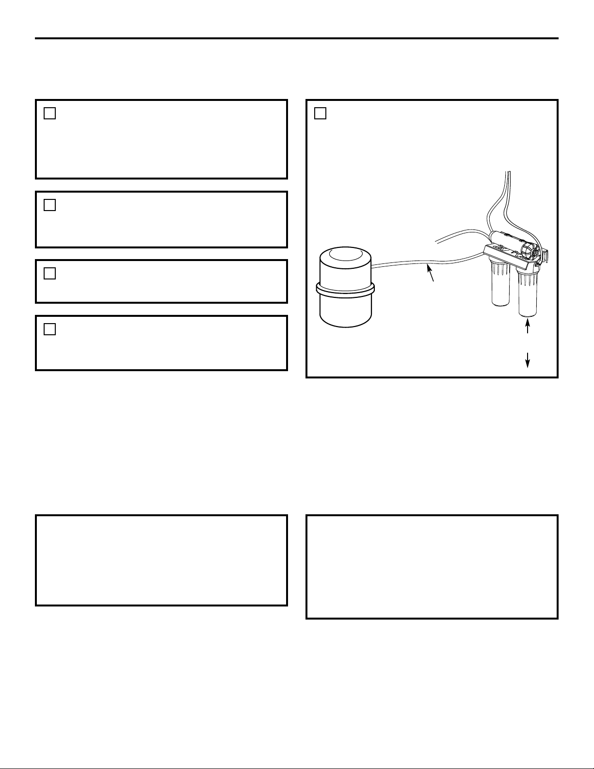
5
Installation Instructions
Things to Check Before Beginning Installation
FEED WATER
The water supply to the undercounter
Reverse Osmosis system must have the
qualities listed in the specifications (see the
Specifications Guidelines section). Municipal
water supplies most often will have these
qualities. Well water may need conditioning—
have the water tested by a water analysis
laboratory and get their recommendations
for treatment.
CAUTION: For water with a hardness
greater than 10 grains (at 6.9 pH), the use of
a softener is recommended. Failure to install
a softener will reduce the life of the Reverse
Osmosis membrane. See the Specifications
Guidelines section for additional information
on the possible need for a softener.
DRAIN POINT
A suitable drain point and air gap (check your
local codes) are needed for reject water from
the Reverse Osmosis membrane cartridge.
BASEMENT INSTALLATION
If installing in a basement, leave enough
tubing in place during installation to be able
to move unit to floor for ease at servicing and
making filter/membrane changes. Additional
tubing and fittings required.
RO FAUCET
The RO product water faucet installs on the
sink or on the countertop next to the sink.
Often, it is installed in an existing sink spray
attachment hole or a hole may be drilled.
Space is required underneath for tubing to
and from the faucet, and for securing the
faucet in place. All faucet connections and
installation procedures are done on or above
the sink or countertop. Refer to illustration
above.
Storage tank
Sink p-trap
HOT COLD
Drain adapter
3/8″ black drain tubing
RO product water faucet mounted
through sink or countertop
Feed water
adapter
Yellow
(inlet)
Orange
1/4″ black
Blue
(to faucet)
Page 6
Installation Instructions
FEED WATER SUPPLY
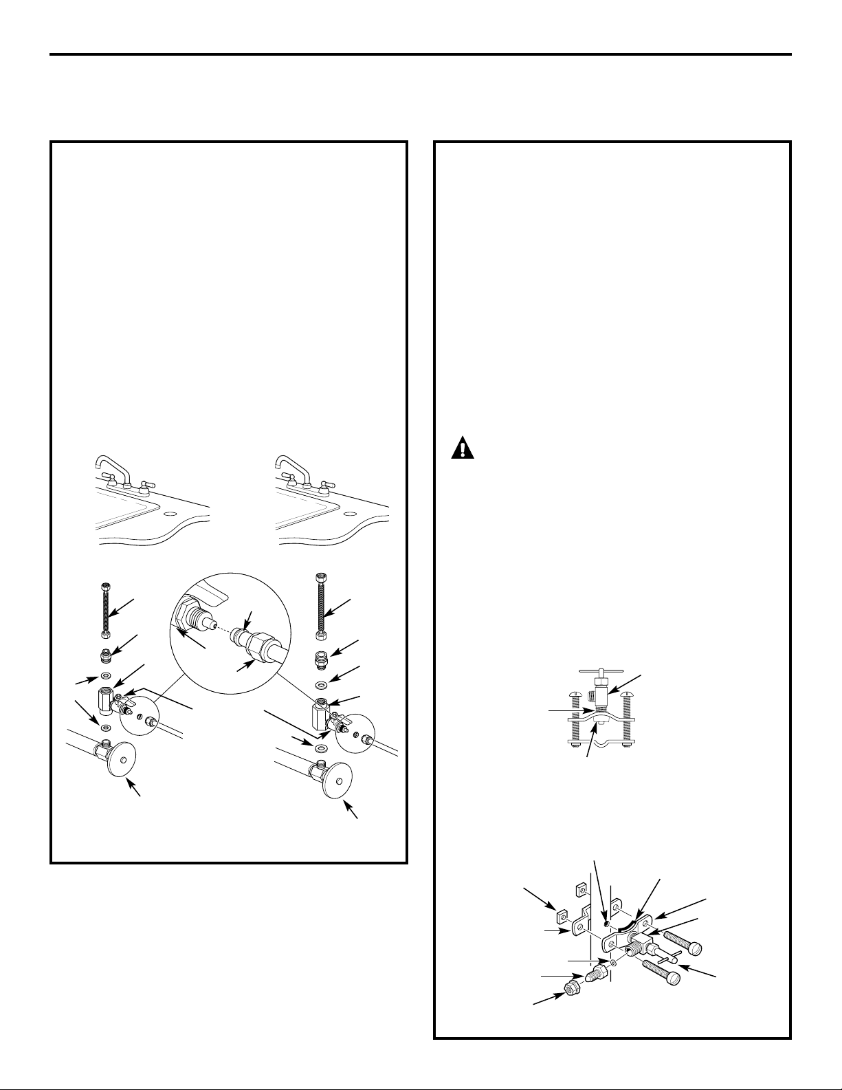
Check and comply with local plumbing codes as you plan, then install a cold feed water supply fitting.
A. PREFERRED INSTALLATION
1. Close the cold water supply valve under
the sink.
2. Unscrew the flexible tubing from the
supply valve that connects to the COLD
water riser.
3. Install the feed water adapter* that is the
diameter to match either the 1/2″ or 3/8″
plumbing in your location. DO NOT
OVERTIGHTEN.
*Notice the direction of the feed water
adapter and coupling. It is installed
differently in order to match either the
1/2″ or 3/8″ plumbing in your location.
B. OPTIONAL HOME INSTALLATION
Where codes permit (Requires additional parts)
*For 1/2″ OD or larger metal tubing only.
NOTE: Codes in the state of Massachusetts
require installation by a licensed plumber and
do not permit the use of the saddle valve. For
installation, use plumbing code 248-CMR of the
Commonwealth of Massachusetts.
Saddle valve is available through GE Parts
and Services at 1.800.626.2002, part number
WS15X10023. Self piercing saddle valves are
not recommended.
1. Turn off the cold water supply and attach
saddle valve as shown in illustration
below.
DANGER: Many homes are
electrically grounded through the plumbing.
To protect yourself from serious injury or
fatal shock, use a battery-powered hand drill
only to make the hole. DO NOT USE AN
ELECTRIC DRILL.
2. Close the water supply valve by turning
the handle clockwise.
3. Open the main water supply valve and
several house faucets to purge air from
the system. Close faucets when water
runs smoothly.
Snug valve into bracket
(DO NOT OVERTIGHTEN)
Some threads
should be visible
Rubber gasket
Optional water supply connection (using saddle valve)*
Pre-drill
1/4″ hole
Seal—make sure
the seal is in place
Clamp X
Nut (2)—not
required if holes
in clamp are
threaded
Valve
Handle
Tubing adapter
Washer
Compression
nut
Clamp Z
Use to connect the tubing
*For 1/2 ″ OD or larger metal tubing only.
6
For 3/8″ Plumbing For 1/2″ Plumbing
Faucet
tubing line
Coupling
Adapter
Inlet valve
Cold water
supply valve
Faucet
tubing line
Cold water
supply valve
Coupling
Adapter
Gasket
Gasket
Ferrule
Inlet valve
Nut
Gasket
Page 7
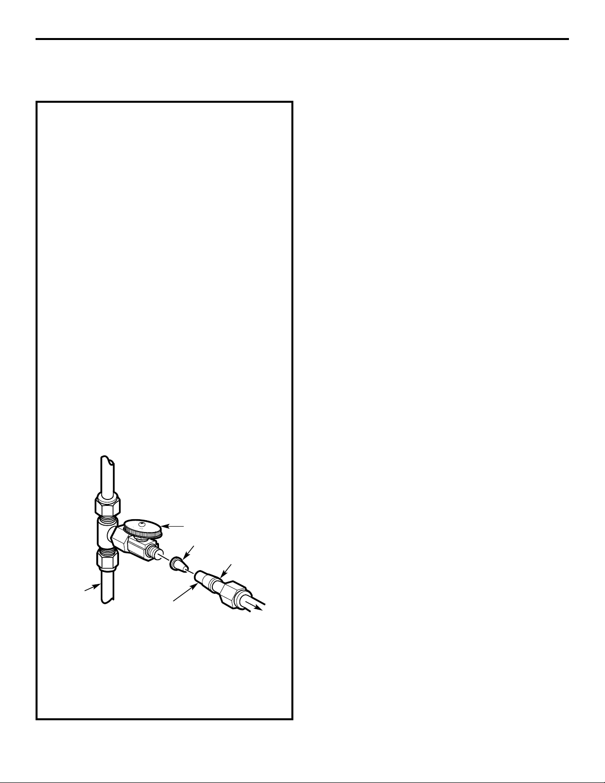
Installation Instructions
C. INSTALLATION IN A
REMOTE LOCATION
(requires additional part)
1. Turn off the cold water supply.
2. Complying with plumbing codes, install a
fitting on the cold water pipe to adapt 1/4″
OD tubing. A typical connection is shown
in illustration below. Make sure a water
supply valve is used.
3. If the RO unit is to be installed more than
6 feet from the valve, replace the yellow
tubing with a longer length of GE 1/4″
tubing. A 33 foot length of 1/4″ tubing is
available through GE Parts and Services
at 1.800.626.2002, part number
WS07X10018. DO NOT SUBSTITUTE
TUBING OF UNKNOWN QUALITY.
4. If the RO unit is to be installed more than 6
feet from the faucet, replace the blue tubing
with a longer length of GE 3/8″ tubing. A 33
foot length is available through GE Parts
and Services at 1.800.626.2002, part number
WS07X10019. See Faucet Installation on
page 8 for more details. DO NOT
SUBSTITUTE TUBING OF UNKNOWN
QUALITY.
If you are using copper tubing, DO NOT
connect it directly onto the RO unit. Purchase a
connector and use a short length of the yellow
tubing provided to make final connection to RO.
Do not use copper tubing to attach to icemaker
or faucet.
7
Insert (not included)
Cold
water
pipe
1/4″ (yellow) tubing
to inlet
Ferrule
Water supply valve
To RO
Page 8
Installation Instructions
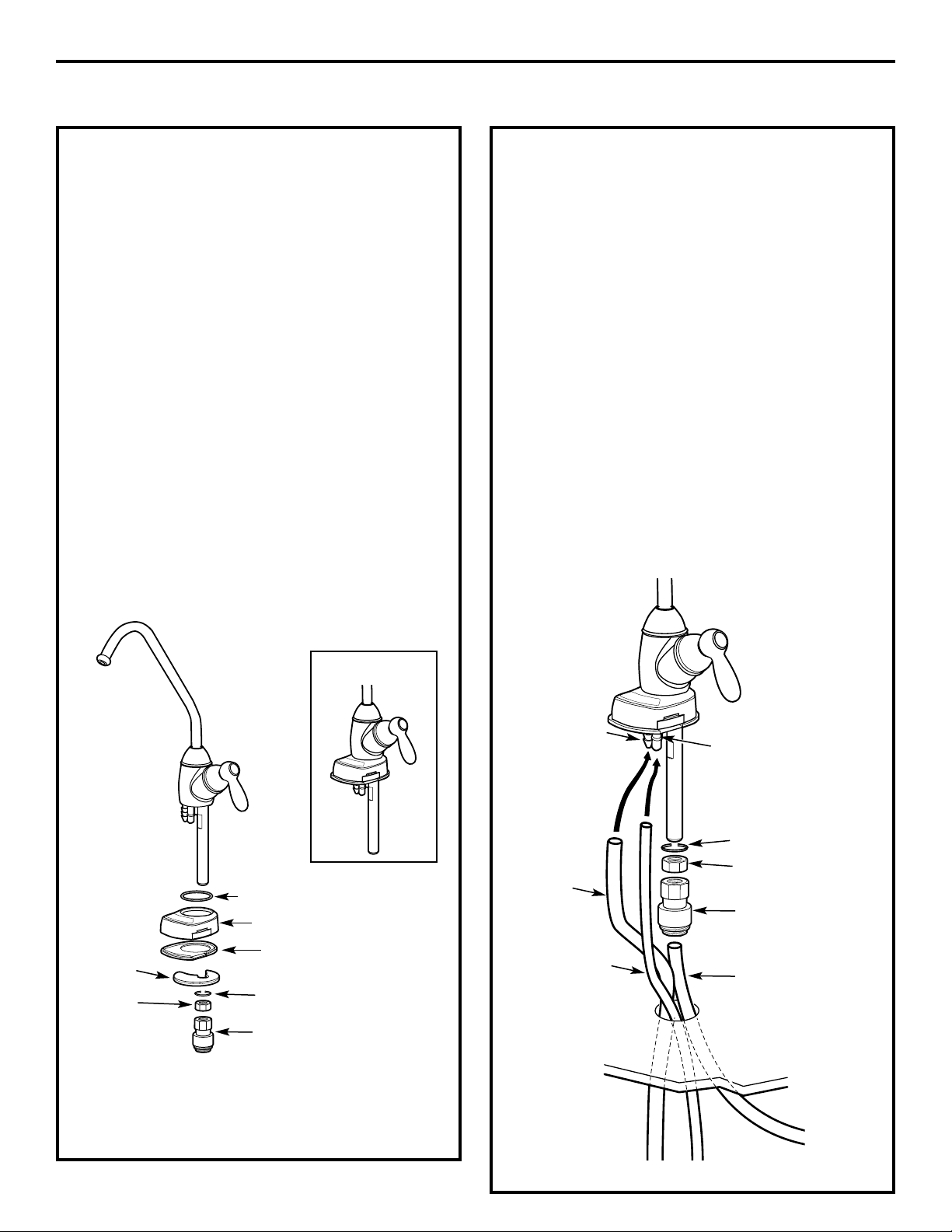
FAUCET INSTALLATION
Be sure there is room underneath the sink to
make the needed connections. Select one of
the following locations to install the faucet:
• In an existing sink spray attachment or soap
dispenser hole.
• In a hole to be drilled in the sink top.
• In a hole to be drilled in the countertop,
next to the sink.
NOTE: Be sure the faucet base will fit flat
against the surface at the selected location
so the gasket will seal.
1. If drilling is needed, make a 1-1/4″ dia.
hole. Be sure to use the proper procedure
for drilling porcelain or stainless steel.
2. Insert the faucet spout into the body.
Tighten cap until snug.
3. Feed the blue, 1/4″ black and 3/8″ black
tubes up through the hole in the
countertop or sink.
4. Feed the two black tubes up through the
gasket, faucet base and O-ring.
NOTE: For ease of service and maintenance,
keep tubing lengths long enough so removal
of the Reverse Osmosis system from under
the sink is possible.
5. Push the 1/4″ black and 3/8″ black tubing
onto their respective barb fittings on the
body.
6. Seat the base and body together. Make
sure the O-ring and gasket are in place
when the base meets the body. The faucet
handle will be at the 3 o’clock position
with respect to the base.
7. Slide the lock washer onto the threaded
stem of the body, then thread the brass
nut onto the stem. Screw about halfway up.
8. Screw the tubing adapter to the threaded
stem of the body.
9. Push the blue tubing into the adapter. It
should go in about 1/2″. Pull on it to make
sure it is installed securely.
10. Feed the tubing and stem back down
through the 1-1/4″ hole.
11. Under the counter, insert the mounting
disk above the lock washer and tighten
the brass nut until snug.
Mounting
disk
Base
Nut
Handle
Spout
Gasket
Tubing adapter
Lock washer
O-ring
Cap
ASSEMBLED
3/8″ barb
fitting
Black 3/8″
tubing,
27″ long
Black 1/4″
tubing
1/4″ barb
fitting
Tubing adapter
Blue 3/8″ tubing
Nut
Lock washer
Body
From RO
From ROTo drain
8
Page 9
Installation Instructions
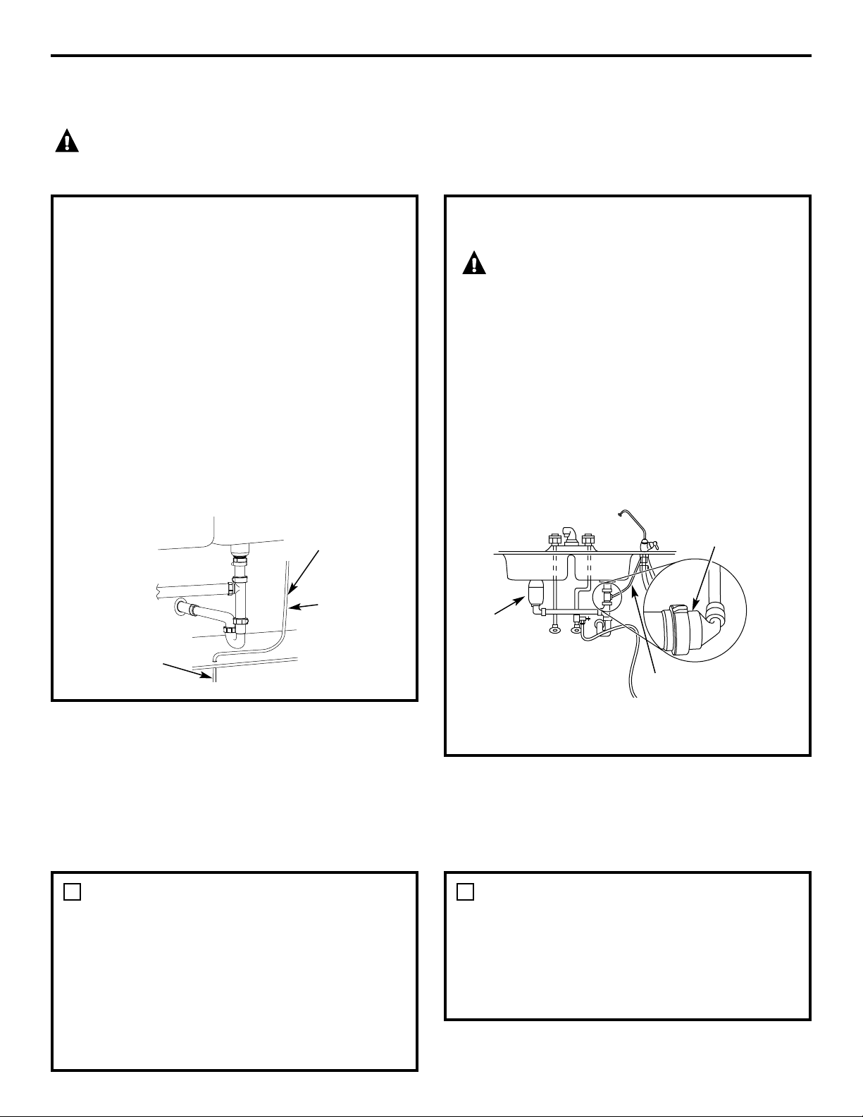
FILTRATION DRAIN CONNECTION INSTALLATION
Check and comply with all state and local plumbing codes as you plan.
CAUTION: The options detailed in this section are the ONLY approved installation
configurations. Do not use any drain saddle device.
OPTION A: BASEMENT ACCESS
INSTALLATION
Route the drain line (1/4″ black line)
DIRECTLY from the Reverse Osmosis system
to a standpipe in the basement, by-passing
the air gap provided in the faucet. The drain
line may also be routed in the basement to a
floor drain or washtub, provided that the air
gap in the basement is maintained. Avoid
dips, loops or low spots in the drain line.
The basement air gap and drain installation
configuration must conform to all local codes.
Special air gap fittings are available from
your local hardware store to connect the
drain line to the top of the standpipe.
Drain line from
Reverse Osmosis
by-passing faucet
air gap
Maintain air gap
at drain point
in basement
1/4″ Black
tubing
OPTION B: DRAIN LINE ADAPTER
INSTALLATION
CAUTION!
DO NOT INSTALL DRAIN LINE ADAPTER
DOWNSTREAM FROM DISPOSER.
Install the provided drain line adapter under the
sink as shown. The baffle-tee provided must be
in place (purchase and install if necessary) to
prevent a clog in the Reverse Osmosis drain
line. Route the drain line (3/8″ black) from the
faucet air gap to the drain line adapter, ensuring
that there are no dips, loops or low spots in the
line that could result in a clogged drain line.
The tubing must be cut to length to provide
a straight routing from the faucet to the drain.
Drain noise in the sink drain is normal when
the Reverse Osmosis system is operating.
FAUCET DRAIN TUBING AND WATER SUPPLY TUBING
If OPTION A: BASEMENT ACCESS INSTALLATION (see Filtration Drain Connection Installation section,
above) was used, go to Step 2.
If OPTION B: DRAIN LINE ADAPTER
INSTALLATION was used, connect the
faucet drain tubing by running the 3/8″
black tubing from the 3/8″ faucet barb
to the drain fitting (installed in Filtration
Drain Connection Installation section,
above). Keep this tubing run as short and
straight as possible, without loops, dips
or low spots. Cut the tubing as needed
and insert into the drain fitting.
1
To connect the water supply tubing:
Run the 1/4″ yellow tubing from the Reverse
Osmosis inlet to the feed water adapter
(see illustrations in the Feed Water Supply
section). Connect the tubing as applies (see
Feed Water Supply section) and tighten the
nut securely.
2
9
Drain line adapter
in different line
from disposer
HOT COLD
Disposer
Drain line is straight
Page 10
Installation Instructions
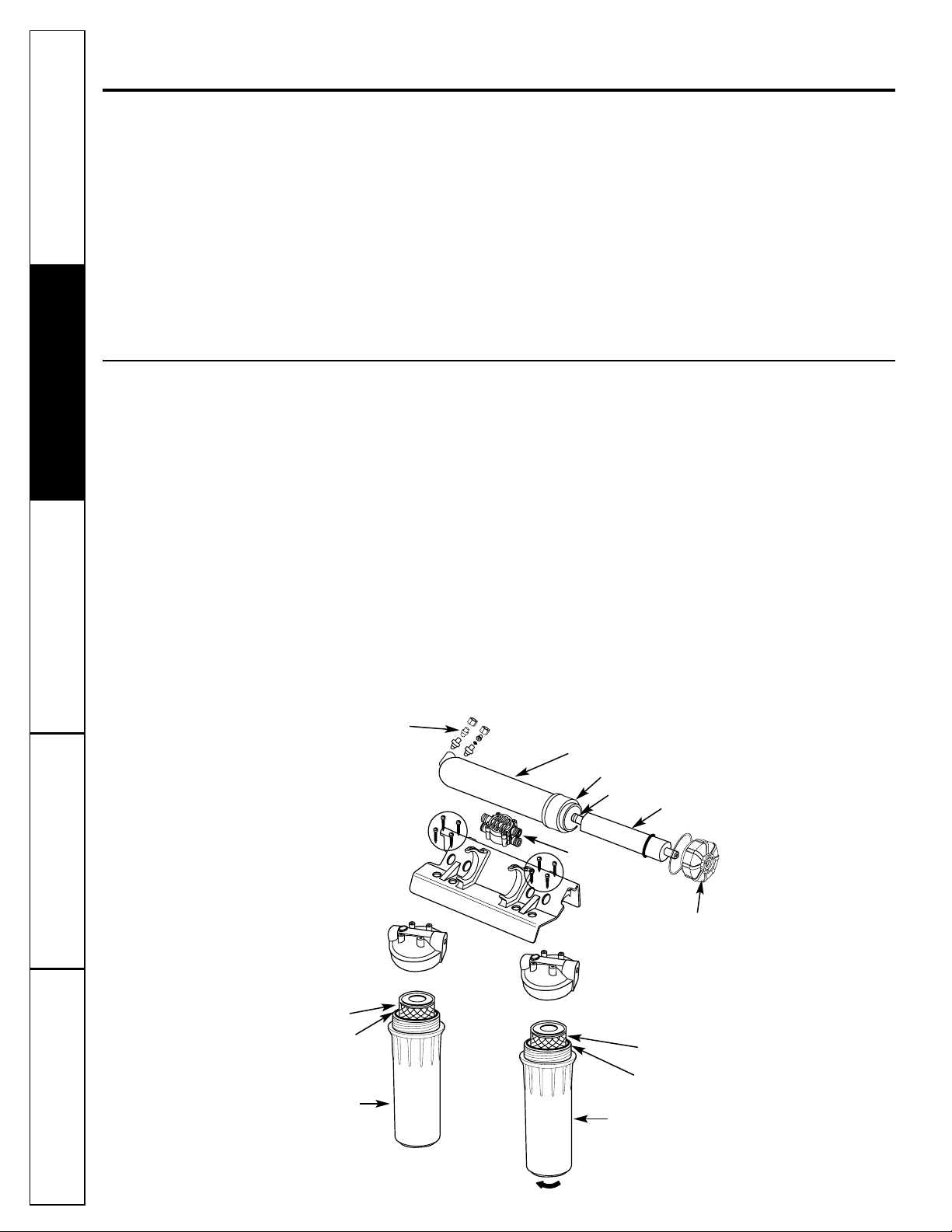
REVERSE OSMOSIS SYSTEM ASSEMBLY
AND STORAGE TANK INSTALLATION
NOW THAT YOUR REVERSE OSMOSIS SYSTEM
IS INSTALLED…SANITIZE!
Sanitize upon installation and after servicing
inner parts, including replacement of prefilter,
postfilter and the Reverse Osmosis cartridge.
It is important to wash hands with antibacterial soap before handling inner parts of
the system. See the Sanitization section.
CAUTION: If installing unit in new
construction, ensure that house plumbing is
flushed thoroughly before opening the water
supply valve. Also, before sanitizing, be sure
to remove all cartridges as described in the
Sanitization section. Chlorine will destroy the
Reverse Osmosis cartridge.
Hold the Reverse Osmosis assembly up
to the wall surface where you will install it.
Mark locations for the screws. The arrows
on the top of the bracket show the location
of the screw holes.
1
Connect the tubing to the storage tank: Run
the length of 3/8″ orange tubing from the
tee fitting on the Reverse Osmosis module
to the tank inlet fitting.
5
Wood screws are included for fastening
to a wood surface. Provide other screws
as needed.
2
Hang the Reverse Osmosis assembly
on the screws.
3
Apply pipe thread sealing tape to the tank
fitting. Insert into tank threads. Tighten with
a wrench.
4
10
Storage
tank
To faucet
Supply line
Orange tubing
2″ minimum clearance
for changing cartridges
Page 11
Installation Instructions
PREFILTER, POSTFILTER AND RO CARTRIDGE
REPLACEMENT PROCEDURE, INCLUDING SANITIZATION
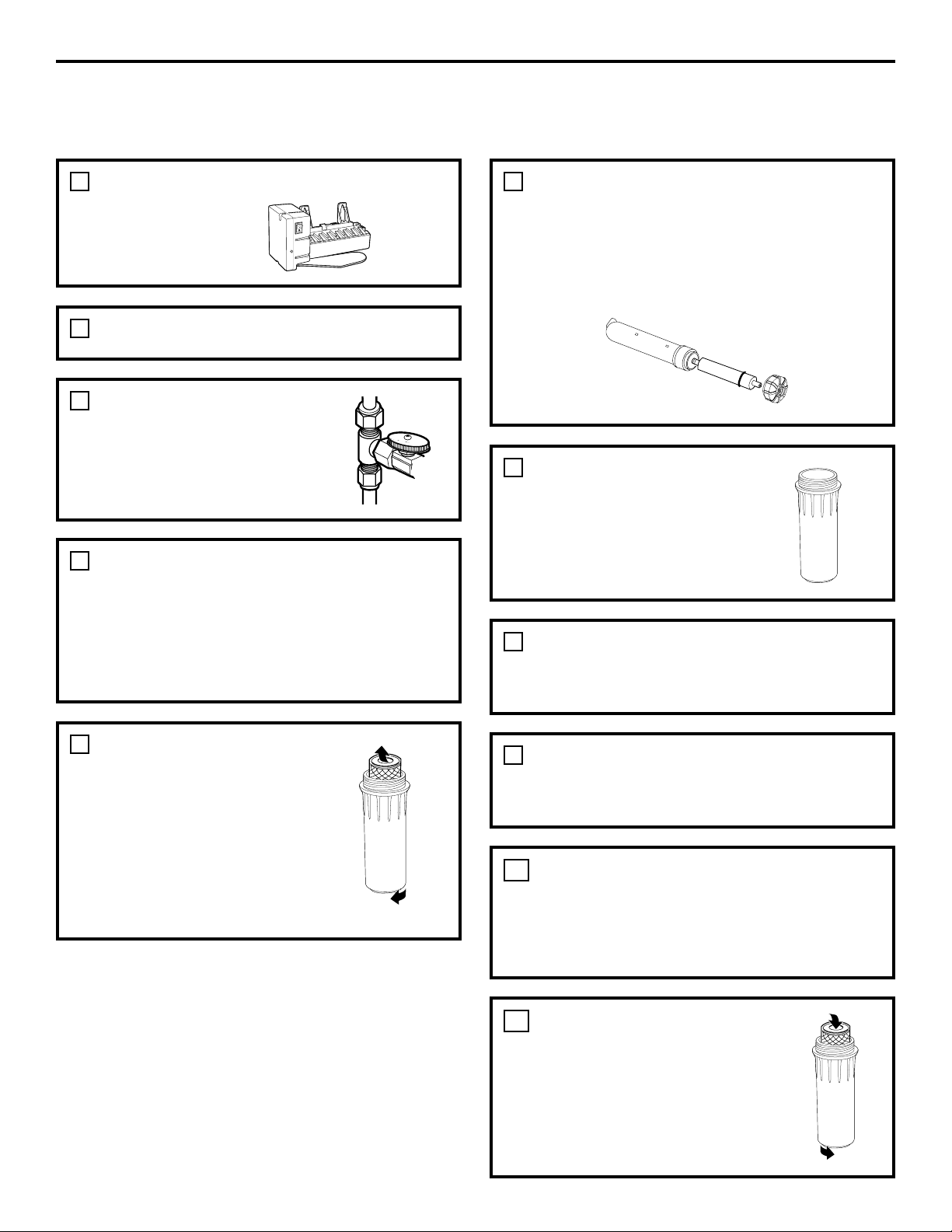
Turn OFF the icemaker (if attached to the
RO system).
1
Wash your hands with anti-bacterial soap.
2
Turn off water supply
to RO system.
3
Remove cap from RO cartridge housing
(unscrew tubing first, on some models).
Use pliers to remove the RO cartridge. Place
in a clean plastic bag or discard if replacing.
Thoroughly wipe inside of housing and cap
with a paper towel or dish brush moistened
with dish soap. Rinse well.
6
Turn on RO faucet. Drain tank (may take
several minutes). Turn off RO faucet.
CAUTION: Failure to close the water
supply valve or tank shutoff valve will cause
water to spray or run when sumps are
removed.
4
Remove the sumps.
Be careful—sumps will be
full of water.
Discard filters. Thoroughly
wash sumps with dish soap.
Thoroughly wipe inside of
heads with a paper towel
moistened with dish soap.
Rinse well.
5
Replace empty postfilter
sump.
7
Fill prefilter sump with water to within 1″
of O-ring. Add 2 oz. (4 Tbsp.) ordinary
household bleach. Replace prefilter sump.
8
Turn on water supply. Open RO faucet until
water begins to flow, then close. Allow
system to fill for 1 minute.
9
Open faucet and allow water to flow for 10
minutes. Close faucet for one minute more,
then open and allow water to flow for
another 10 minutes, or until bleach odor is
gone. Turn off water supply again. Drain RO.
10
Remove sumps. Insert filters.
Lubricate o-ring with food-grade
silicone grease, if necessary.
(Do not use petroleum jelly).
Tighten sumps securely.
11
11
Page 12
Installation Instructions
PREFILTER, POSTFILTER AND RO CARTRIDGE
REPLACEMENT PROC., INCLUDING SANITIZATION (cont.)
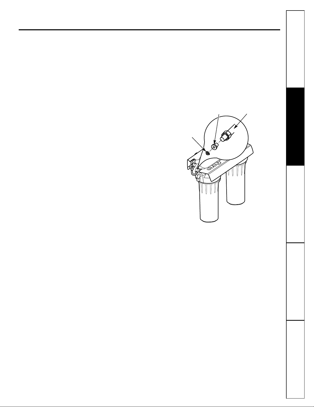
Remove cap from RO cartridge housing.
Install RO cartridge, O-ring end first.
Lubricate cover O-ring with food-grade
silicone grease, if necessary. (DO NOT use
petroleum jelly). Tighten cap securely.
12
Change the batteries in the filter change
indicator:
• Use a small, flat blade screwdriver or coin
and carefully open the battery compartment.
• Install the CR2032 battery (+) side down into
the tray.
• Slide the tray into the base and snap-lock
into place.
• The light will flash 5 times to indicate
proper installation. After 6 months of use,
the light will flash again, indicating the
proper time to replace the filter. Install a
new CR2032 battery after 6 months of use.
15
If you only replaced the prefilter and
postfilter, allow faucet to run 5 minutes to
remove harmless carbon particles. If you
replaced the RO cartridge, fill and empty
the storage tank three times, until taste
and odor from food grade membrane
preservative is gone.
16
Once storage tank is full, turn on icemaker.
17
Turn on water supply. Allow to fill. (May
take up to four hours). Check for leaks.
14
If you replaced the RO cartridge, also
replace the flow control and screen.
(Unscrew the black 1/4″ line from the fitting.
Remove flow control with clean knife edge.
Remove screen with a clean toothpick).
Tighten the nut hand-tight and then tighten
1/4 turn with pliers. DO NOT OVERTIGHTEN.
13
12
Flow
control
Screen
Compression
nut
1/4″ Black tubing
Page 13
Care and cleaning of the reverse osmosis system. www.GEAppliances.com
To obtain replacement filters, call toll-free GE Appliance Parts at 800.626.2002 (U.S.),
800.663.6060 (Canada–English), 800.361.3869 (Canada–French), or visit the store where
you purchased your reverse osmosis system.
CAUTION: Before servicing the Reverse Osmosis system, close the water supply/saddle valve
and open the RO water faucet. Allow the system to drain.
Prefilter/Postfilter Cartridge Replacement FX12P Carbon Block
Reverse Osmosis Cartridge Replacement FX12M Thin Film Polyamide
The Water Test Kit
To obtain an independent laboratory water test kit, please call Legend Technical Services at
1.800.826.8553 ext. 47 and leave your contact details. They will contact you to find out what water
tests you are interested in, and inform you of the cost of the testing. You will then receive a kit that
will include all necessary tests to properly indicate the performance level of your system. Product
water should be tested a minimum of every six months.
Consumer SupportTroubleshooting TipsOperating InstructionsSafety Instructions Installation Instructions
13
Page 14
Description of the Reverse Osmosis System
Prefilter—Water from the cold supply pipe is
directed to the prefilter cartridge, which is inside
the sump.
The prefilter is a replaceable sediment
cartridge containing activated carbon. The
cartridge removes sand, silt, dirt, other sediments
and up to 2.0 ppm of chlorine from the feed
water. The prefilter reduces chlorine in the feed
water because CHLORINE DESTROYS THE REVERSE
OSMOSIS MEMBRANE. Filtered, clean, chlorinereduced water flows from the prefilter to the
Reverse Osmosis cartridge.
Storage Tank—The storage area holds up to
3 gallons of product water. A diaphragm inside
the tank keeps water pressurized for fast flow
to the faucet when drinking water is needed.
Check Valve—A check valve is built into one end
of the Reverse Osmosis housing. The check valve
prevents a backward flow of product water from
the storage area. A backward flow could cause the
Reverse Osmosis membrane to rupture.
Automatic Shutoff Valve—To conserve water, the
drinking water system has an automatic shutoff.
When the storage tank has filled to capacity and
the drinking water faucet is closed, pressure closes
the shutoff. Water flow to the Reverse Osmosis
housing is shut off until drinking water is used
again, and pressure drops in the Reverse Osmosis
system.
14
About the reverse osmosis system.
What the Reverse Osmosis System Does
Reverse Osmosis removes Total Dissolved Solids
(TDS) and organic matter from water by diffusing
it
through a special membrane. The membrane
separates minerals and impurities from the water
and they
are flushed to the drain. High quality
product water goes directly to the drinking water
faucet or to the storage tank. The system makes
a good supply of drinking water each day; see
Specification Guidelines. How much it makes
depends on the feed water supply pressure,
temperature and quality.
The carbon prefilter and postfilter are replaceable
cartridges. The prefilter removes chlorine while
also filtering sediments. The postfilter removes any
other undesirable tastes and odors before you use
the water.
Troubleshooting TipsConsumer Support Troubleshooting Tips
Installation Instructions
Safety InstructionsOperating Instructions
Sump
Postfilter
cartridge
Prefilter cartridge
Reverse Osmosis cartridge
Reverse Osmosis housing
Turn sump this way to remove
O-ring housing
Reverse Osmosis
housing cap
Sump
O-ring on top lip of sump
O-ring on top lip of sump
O-ring end
Check valve
Automatic
shutoff valve
Page 15
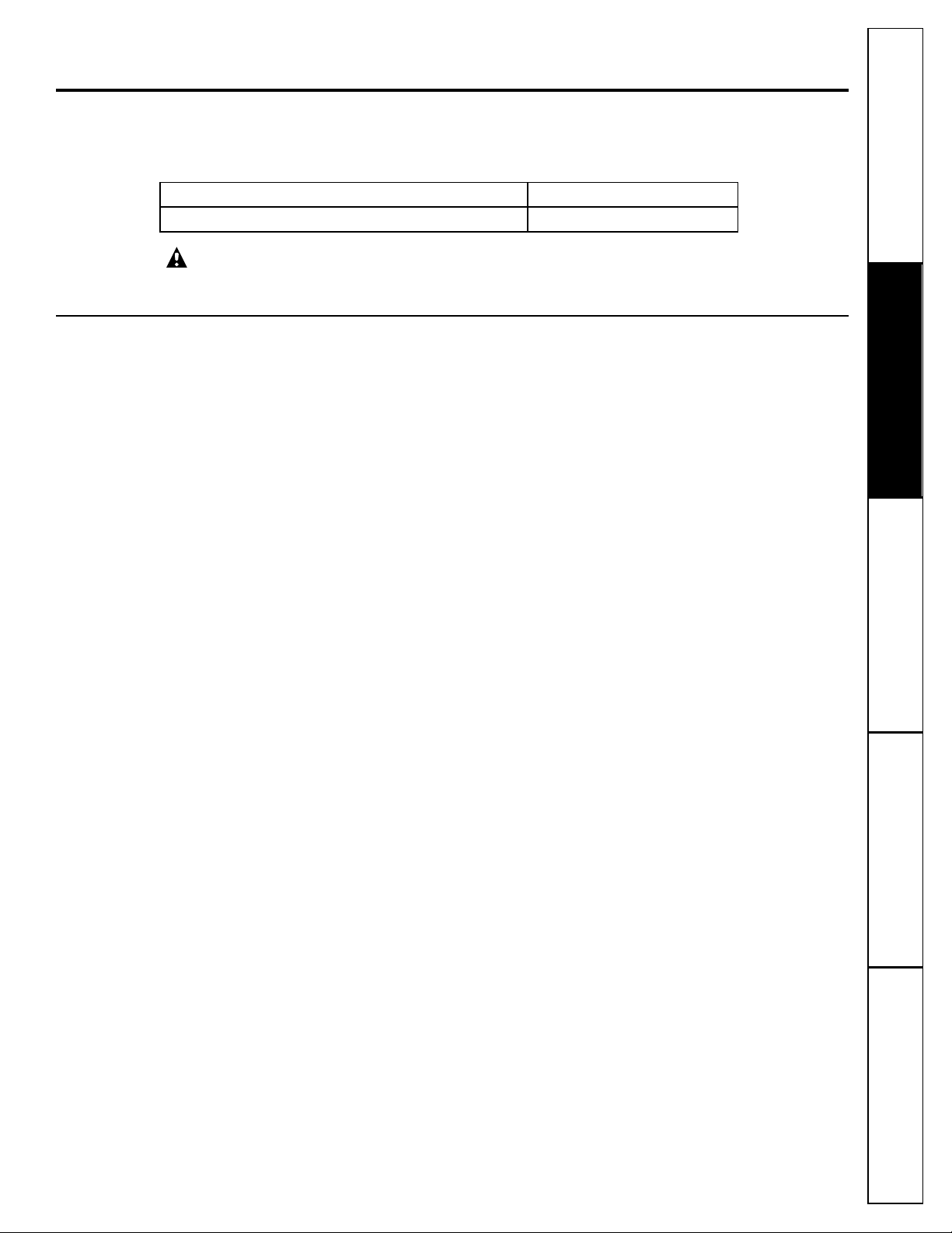
Reverse Osmosis Cartridge—The cartridge, inside
the Reverse Osmosis housing, includes a tightly
wound, special membrane. Water is forced through
the cartridge where the membrane removes the
dissolved solids and organic matter. High quality
product water exits the Reverse Osmosis housing
and goes to the storage tank. Reject water, with
the dissolved solids and organic matter, leaves the
housing and is discharged to the drain through
tubing.
Postfilter—After leaving the storage area,
but before going to the system faucet, product
water goes to the postfilter which is inside the
sump. The postfilter is also a replaceable
sediment cartridge that contains activated
carbon. Any remaining tastes, odors or
sediments are removed from product water
by the postfilter. Clean, high quality drinking
water flows through the tubing and to the
system faucet.
System Monitor—
A timer is provided in the faucet
base to remind you when it is time to replace
your prefilter and postfilter. Replace the filters
when the blue light begins to flash in order to
protect the RO membrane and keep the system
functioning properly. Be sure to remove and
replace the battery at the same time to reset
the timer.
Flow Control—The flow control regulates the flow
of water through the Reverse Osmosis cartridge
at the required rate to produce high quality
water. The control is located in the Reverse
Osmosis housing drain port. A small, coneshaped screen fits over the front end of the flow
control to prevent clogging due to sediments in
drain water. The flow control and screen should
be replaced each time the Reverse Osmosis
membrane cartridge is changed.
15
www.GEAppliances.com
Screen
Flow control
1/4″ black tubing
(to drain)
Consumer Support
Troubleshooting Tips
Operating InstructionsSafety Instructions Installation Instructions
Page 16
Consumer Support
Troubleshooting Tips Operating Instructions Safety InstructionsInstallation Instructions
Before you call for service…
Problem Possible Causes What To Do
Sounds you might hear Running water from the unit • This is normal.
to a drain.
Water has air bubbles Air in system after installation. • Will go away after water runs for a while.
and is cloudy
Chlorine taste and/or The ppm of chlorine in your
• If the water supply contains more than 2.0 ppm of
odor in the Reverse water supply exceeds maximum
chlorine,
additional filtering of the water supply to the
Osmosis product water limits and has destroyed the Reverse Osmosis is needed. Correct this condition before
Reverse Osmosis membrane. doing maintenance on the Reverse Osmosis system.
The prefilter is no longer • Replace the Reverse Osmosis membrane cartridge,
removing chlorine from flow control, screen, prefilter and postfilter.
the water supply.
Other taste and/or odor High quality product water • This is normal.
may have a different taste
than what you’re used to.
Low water usage. • Completely drain system and allow to refill.
Contamination in product
•
Use sanitizing procedures.
water storage.
Prefilter and postfilter
• Replace the prefilter and postfilter. If taste and odor
need to be changed and/or persists, replace the Reverse Osmosis cartridge, flow
the Reverse Osmosis cartridge control and screen.
needs to be changed.
Water leaking from Drain side of faucet air gap • Inspect and eliminate restriction or plug. It is important
faucet air gap hole (3/8″ tubing) plugged, restricted that there are no dips, loops or low spots in the drain line
or incorrectly connected to the from the faucet air gap to the drain pipe. Refer to the
drain point. Filtration Drain Connection Installations section, for proper
drain connection. If drain line adapter was used as the
drain point, periodic inspection/cleaning is recommended.
System makes product This is normal. • Water flow rate will be lower than your regular faucet.
water slowly
Water supply to the Reverse • Increase water pressure, precondition the water, etc.,
Osmosis system not within as needed to conform to specification guidelines before
specifications. doing maintenance on the Reverse Osmosis system.
Prefilter cartridge plugged • Replace the prefilter and postfilter.
If rate does not
with sediments and/or the
increase,
replace the Reverse Osmosis cartridge, flow
Reverse Osmosis cartridge control and screen.
plugged with sediments.
Faucet light blinking Prefilter and postfilter • Replace filters. Don’t forget to sanitize the system when
need replacing. replacing filters.
Timer was not reset when filters • Remove and replace battery in faucet base.
were replaced.
Six months have passed Battery may be dead. • Replace battery. NOTE: Replacing battery resets the
and faucet light is not six-month timer, so be sure to replace prefilter and
blinking postfilter if it is time to do so.
Battery may have been • Any time the battery is removed and reinserted, the
removed recently. six-month timer starts over again. Do not remove battery
unless you wish to restart the timer.
Troubleshooting Tips
Save time and money! Review the chart first and you may
not need to call for service.
16
Page 17
* NOTE: Codes in the State of Massachusetts require installation by a licensed plumber
and do not permit the use of the saddle valve. For installation, use plumbing code 248-CMR
of the Commonwealth of Massachusetts.
Parts list. www.GEAppliances.com
17
Consumer SupportTroubleshooting TipsOperating InstructionsSafety Instructions Installation Instructions
Optional Accessories
Page 18

Consumer Support
Troubleshooting Tips Installation Instructions Safety InstructionsOperating Instructions
18
General Electric parts catalog.
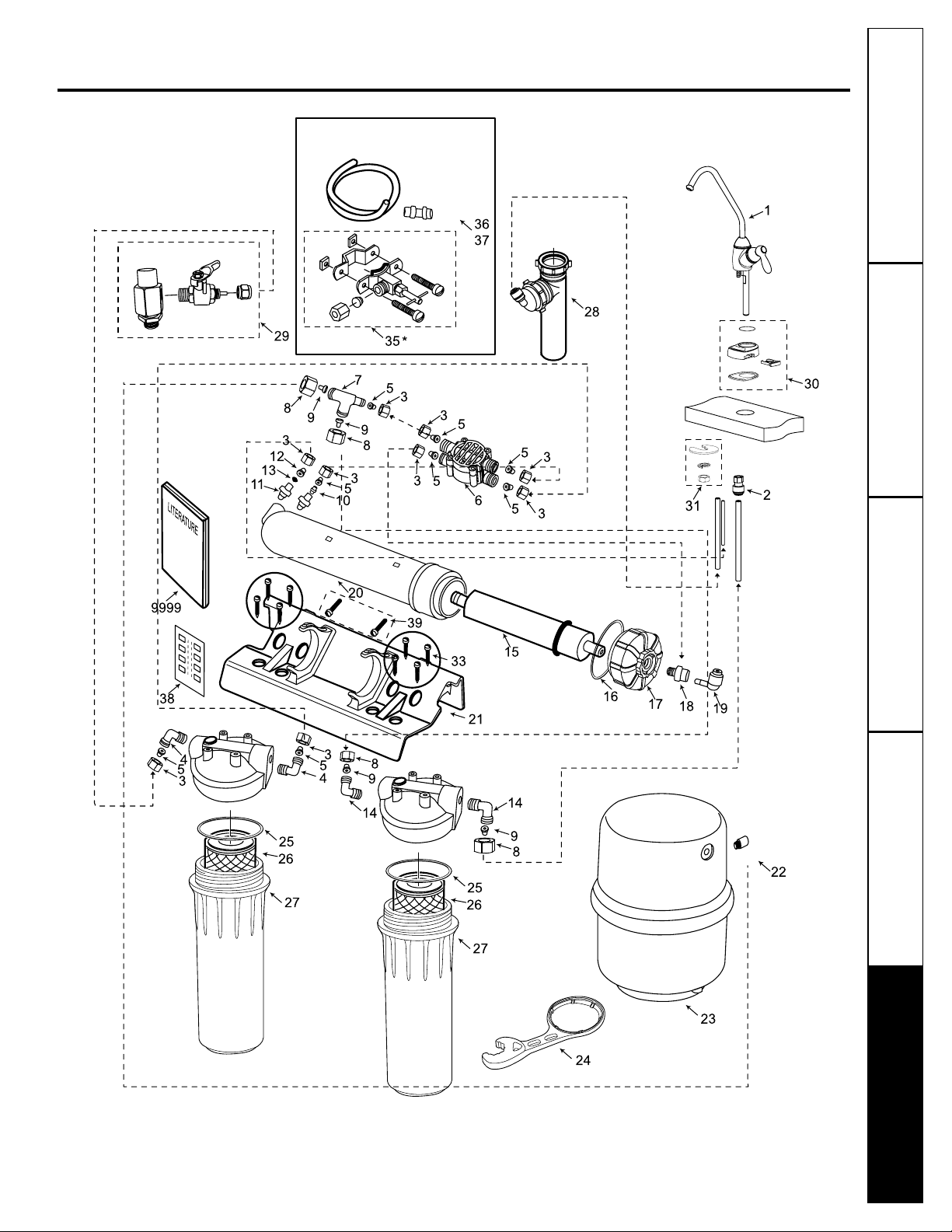
REF. NO. PART NO. PART DESCRIPTION GXRM10GBL
0001 WS15X10037 FAUCET BODY & SPOUT 1
0002 WS22X10037 3/8″ QUICK CONNECT—FAUCET 1
0003 WS22X10005 1/4″ NUT 10
0004 WS22X10026 3/8″ NPT X 1/4″ NUT ELBOW 2
0005 WS22X10006 1/4″ TUBE INSERT 8
0006 WS22X10038 VALVE—AUTO SHUT OFF 1
0007 WS22X10039 1/4″ X 3/8″ X 3/8″ TUBE TEE 1
0008 WS22X10008 3/8″ NUT 4
0009 WS22X10007 3/8″ TUBE INSERT 4
0010 WS22X10040 CHECK VALVE—1/4″ INSERT 1
0011 WS22X10041 1/8″ NPT X 1/4″ FITTING 1
0012 WS03X10016 FLOW CONTROL 1
0013 WS03X10015 CONE SCREEN 1
0014 WS22X10002 3/8″ NPT X 3/8″ NUT ELBOW 2
0015 FX12M RO MEMBRANE 1
0016 WS03X10045 O-RING—RO MEMBRANE HSNG 1
0017 WS31X10025 CAP—RO MEMBRANE HSNG 1
0018 WS22X10042 1/8″ NPT X 1/4″ FITTING 1
0019 WS22X10043 ELBOW—1/4″ STEM X 1/4″ 1
0020 WS20X10006 HOUSING—RO MEMBRANE 1
0021 WS28X10039 BRACKET 1
0022 WS22X10044 CONNECTOR—3/8″ X 3/8″ MNPT 1
0023 WS32X10019 STORAGE TANK 1
0024 WX5X140 WRENCH 1
0025 WS03X10038 O-RING, SUMP HOUSING 2
0026 FX12P CARBON BLOCK CARTRIDGE 2
0027 WS20X10007 SUMP HOUSING 2
0028 WS18X10006 DRAIN LINE ADAPTER—DLA9 1
0029 WS18X10009 ADAPTER KIT—FEED WATER 1
0030 WS10X10028 FAUCET BASE ASM 1
0031 WS02X10031 WASHER & NUT—FAUCET 1
0033 WS02X10032 SCREWS, BRACKET 8
0034 WS31X10026 HOUSING HEAD 2
0035 WS15X10023 SADDLE VALVE 1
0036 WS07X10018 TUBING—1/4″ X 33′—WHITE 1
0037 WS07X10019 TUBING—3/8″ X 33′—WHITE 1
0038 WS01X10013 NITRATE TEST STRIP 1
0039 WS02X10033 MOUNTING SCREWS 2
9999 49-50106 OWNER’S MANUAL/INSTALLATION 1
INSTRUCTIONS
* NOTE: Codes in the State of Massachusetts require installation by a licensed plumber
and do not permit the use of the saddle valve. For installation, use plumbing code 248-CMR
of the Commonwealth of Massachusetts.
To obtain replacement parts, call toll-free 800.626.2002 (U.S.), 800.663.6060 (Canada–English),
800.361.3869 (Canada–French).
Page 19

19
Notes.
Consumer SupportTroubleshooting TipsOperating InstructionsSafety Instructions Installation Instructions
Page 20
GE Reverse Osmosis System Warranty.
20
For The Period Of: GE Will Replace:
One Year Any part of the Reverse Osmosis Filtration System which fails due to a defect in materials or
From the date of the workmanship. During this limited one-year warranty, GE will also provide, free of charge, all labor
original purchase (does not include service trip to home) to replace the defective part. All warranty service will be
provided by a GE SmartWater™Authorized Servicer.
All warranty service provided by our SmartWater™Authorized
Servicer Network. To schedule service on-line, 24 hours a day,
contact us at www.GEAppliances.com, or call toll-free
800.GE.CARES (U.S.), or 866.777.7627 (Canada).
■ Service trips to your home to teach you how to use the
product.
■ Improper installation, delivery or maintenance.
■ Failure of the product if it is abused, misused, or used
for other than the intended purpose.
■ Filters or membranes.
■ Defects that result from improper installation or damage
not caused by GE.
■ Liability on the part of GE under this or any other
warranty for any indirect or consequential damage.
■ Products that are used for commercial or industrial
applications.
■ Use of this product where water is microbiologically
unsafe or of unknown quality, without adequate
disinfection. Systems certified for cyst reduction may be
used on disinfected water that may contain filterable cysts.
■ Replacement of house fuses or resetting of circuit
breakers.
■ Damage to the product caused by accident, fire, floods or
acts of God.
■ Incidental or consequential damage caused by possible
defects with this appliance.
■ Damage caused after delivery.
What GE Will Not Cover:
This warranty is extended to the original purchaser and any succeeding owner for products purchased for home
use within the USA. In Alaska, the warranty excludes the cost of shipping or service calls to your home.
Some states do not allow the exclusion or limitation of incidental or consequential damages. This warranty gives
you specific legal rights, and you may also have other rights which vary from state to state. To know what your
legal rights are, consult your local or state consumer affairs office or your state’s Attorney General.
THIS WARRANTY IS INTENDED TO BE IN LIEU OF ALL OTHER WARRANTIES, WHETHER EXPRESS OR IMPLIED,
INCLUDING THE WARRANTIES OF MERCHANTABILITY AND FITNESS FOR A PARTICULAR PURPOSE.
Warrantor: General Electric Company. Louisville, KY 40225
Staple your receipt here.
Proof of the original purchase
date is needed to obtain service
under the warranty.
Consumer Support
Troubleshooting Tips Installation Instructions Safety InstructionsOperating Instructions
Page 21

21
Mesures de sécurité
Mesures de sécurité . . . . . . . . . . . . . . . . . .22
Guide des spécifications . . . . . . . . . . . . . .23
Instructions d’installation
Alimentation d’eau . . . . . . . . . . . . . . .26, 27
Avant de commencer l’installation . . . . . .24
Conduite pour la vidange du robinet
et pour l’alimentation d’eau . . . . . . . . . . .30
Installation de l’ensemble du système . . . .30
Installation du robinet . . . . . . . . . . . . . . . .28
Outillage et matériel requis . . . . . . . . . . . .24
Points à vérifier avant de commencer
l’installation . . . . . . . . . . . . . . . . . . . . . . . .25
Raccordements à la conduite
de vidange . . . . . . . . . . . . . . . . . . . . . . . .29
Entretien et nettoyage
Désinfection . . . . . . . . . . . . . . . . . . . . . . .31
Remplacement des cartouches
pré-filtre, post-filtre et osmose inversée . .31, 32
Trousse pour le test d’eau . . . . . . . . . . . . .33
Fonctionnement
Au sujet du système de filtration par
osmose inversée . . . . . . . . . . . . . . . . . .34, 35
Conseils de dépannage . . . . . . . . . . . . . .36
Soutien au consommateur
Garantie . . . . . . . . . . . . . . . . . . . . . . . . . . .39
Liste des pièces/catalogue . . . . . . . . . .37, 38
Soutien au consommateur . . . . . . . . . . . .40
La section Française.
Numéro de modèle : __________________________
Numéro de série : ____________________________
Vous les trouverez sur le support du corps de filtre.
Service à la clientèleConseils de dépannageFonctionnement
Mesures de sécurité
Installation
Page 22

Service à la clientèle Conseils de dépannage
Fonctionnement Mesures de sécuritéInstallation
22
MESURES DE SÉCURITÉ IMPORTANTES.
LISEZ D’ABORD TOUTES LES INSTRUCTIONS.
■ Vérifiez avec les travaux publics locaux ou de votre
état quels sont les codes régissant la plomberie et les
aménagements sanitaires. Vous devrez vous y conformer
lors de l’installation du système du système de filtration
par osmose inversée. Il est recommandé de faire appel à
un installateur qualifié.
■ Si la pression de l’eau arrivant à l’habitation dépasse la
valeur maximale de 125 livres/po2, montez un détendeur
dans la conduite d’arrivée de l’eau au système de filtration.
■
Assurez-vous que l’eau est conforme au Guide des
spécifications. Si les conditions de l’eau ne sont pas
connues, contactez votre compagnie municipale de
fourniture d’eau ou votre service de santé local pour
obtenir une liste des agents de contamination de votre
région et une liste des laboratoires homologués par
votre état pour l’analyse de l’eau de table.
AVERTISSEMENT : Avant la première utilisation
du système de filtration, celui-ci doit être purgé. La
cartouche du système de filtration par osmose inversée
contient un préservatif pour aliments qui doit être purgé
du système. Ce préservatif donne à l’eau un goût et une
odeur désagréables.
■ Cet appareil réduit la fluoration de l’eau de table.
Veuillez consulter votre dentiste pour toute question
à ce sujet.
AVERTISSEMENT : N’utilisez pas l’appareil avec
de l’eau qui n’est pas sûre microbiologiquement ou de
qualité inconnue sans qu’elle n’ait été désinfectée
avant l’entrée ou la sortie de celui-ci. Les appareils
homologués pour la réduction des spores peuvent être
utilisés pour le filtrage de l’eau qui a été désinfectée
pouvant contenir des spores filtrables.
Ce système à été testé pour le traitement de l’eau
contenant de l’arsenic pentavalent (aussi appelé As(V),
As(+5) ou arséniate) à une concentration de 0,050 mg/L
ou moins. Ce système réduit l’arsenic pentavalent, mais
peut ne pas retirer d’autres formes d’arsenic. Ce système
doit être utilisé dans les alimentations en eau contenant
du chlore libre résiduel détectable ou dans les
alimentations en eau qui se sont avérées contenir
seulement de l’arsenic pentavalent. Le traitement à la
chloramine (chlore combiné) n’est pas suffisant pour
assurer la conversion complète de l’arsenic trivalent
en arsenic pentavalent. Veuillez lire la section Faits sur
l’arsenic de la fiche technique de performance pour
des renseignements supplémentaires.
Cet appareil comporte une cartouche avec membrane
remplaçable essentielle pour réduire efficacement les
matières solides totalement dissolvables. Il est nécessaire
de tester l’eau périodiquement afin de s’assurer que
l’appareil fonctionne de manière satisfaisante.
Voyez la
section Au sujet de la trousse de test de l’eau.
Cet appareil
est acceptable pour des concentrations maximum de
nitrates à 27 mg par litre et de nitre à 3 mg par litre en
combinaison appelée N. Il est acceptable pour la
réduction de nitrate/nitre dans de l’eau dont la pression
est égale ou supérieure à 280kPA (40psig).
CONSERVEZ CES INSTRUCTIONS
VEUILLEZ LIRE ET SUIVRE ATTENTIVEMENT
CES MESURES DE SÉCURITÉ.
■ Installez l’appareil ou entreposez-le de telle façon qu’il
ne soit pas exposé à des températures inférieures au
point de congélation ou non à l’abri de tout type de
conditions météorologique. Il sera endommagé par
l’eau qui se congèle. N’essayez pas de traiter de l’eau
dont la température est supérieure à 100 degrés F.
■ Ne branchez pas l’appareil sur une CONDUITE D’EAU
BOUILLANTE. La température de l’eau arrivant au
système doit se trouver entre 40°F au minimum et
100°F au maximum. Voyez le Guide des spécifications.
■ Période prolongée de non-utilisation du système de filtration.
Si le système n’a pas été utilisé au cours d’une période
d’une semaine ou plus, ouvrez le robinet d’eau RO pour
permettre la vidange de celui-ci. Fermez le robinet pour
permettez au système de régénérer l’alimentation en eau.
■ L’installation recommandée est sous l’évier. Toutefois,
l’unité peut être installée dans un lieu éloigné, jusqu’à
une distance de 6 m (20 pi) de l’évier. Du matériau
d’installation supplémentaire peut être nécessaire. Si le
système de filtration par osmose inversée est raccordé à la
machine à glaçons du réfrigérateur, un kit spécial pour la
connexion de la machine à glaçons est nécessaire (RVKIT).
N’utilisez pas de tubes en cuivre pour la connexion entre le
système de filtration par osmose inversée et le réfrigérateur.
AVERTISSEMENT : Débarrassez-vous de tous
les composants non-utilisés ainsi que de l’emballage
après l’installation. Les petites pièces qui restent après
l’installation peuvent constituer un danger d’étouffement
si ingérées.
■
Désinfectez les éléments au cours de l’installation et
après l’entretien des composants internes. Ceci inclut
le remplacement de l’élément de pré-filtrage, l’élément
du post-filtrage et de la cartouche de l’appareil. Il est
important que les mains soient propres lors de la
manipulation des éléments internes du système.
Voyez la section Désinfection du système de filtration
par osmose inversée.
■
Ce système d’osmose inverse contient un élément
remplaçable essentiel à son efficience. Vous ne pouvez
remplacer l’élément d’osmose inverse que par un
élément ayant des caractéristiques techniques identiques,
telles que définies par le fabricant, pour assurer le même
rendement en matière d’efficience et de réduction de
contaminants. Consultez la section Robinet d’arrêt
automatique, page 34.
ASSUREZ-VOUS QUE VOUS SUIVEZ TOUTS
DE VOS CODES D’ÉTAT ET LOCAUX.
AVERTISSEMENT!
Pour votre sécurité, suivez les instructions fournies dans le présent
manuel afin de minimiser les risques de dommages au matériel ou de
blessures corporelles.
PRÉCAUTIONS DE SÉCURITÉ
INSTALLATION ET ENTRETIEN DU SYSTÈME
Avant son utilisation, le système de filtration doit être correctement installé et positionné
conformément aux instructions d’installation.
Page 23

Guide des spécifications.
www.electromenagersge.ca
L’appareil produit une bonne quantité d’eau potable quotidiennement.
Cette quantité est fonction des données suivantes…
Produit – hauteur 38,1 cm (15 po) largeur 35,6 cm (14 po)
profondeur 14 cm (5,5 po)
Quantité maximale de fer, de manganèse, d’hydrogène sulfuré (en ppm) . . . . . . .<0,1
Chlore dans l’eau . . . . . . . . . . . . . . . . . . . . . . . . . . . . . . . . . . . . . . . . . . . . . . . . . . . . . .2,0 ppm admissible maximum
b
Limites pH de l’eau d’admission . . . . . . . . . . . . . . . . . . . . . . . . . . . . . . . . . . . . . . . . .4–10
Production d’eau (de qualité) en gallons par 24 heures . . . . . . . . . . . . . . . . . . . . . .38 L (10 gallons)
a
Pourcentage de rejet des TDS (nouvelle membrane) . . . . . . . . . . . . . . . . . . . . . . . .92,4%
a
Pourcentage de réduction des spores . . . . . . . . . . . . . . . . . . . . . . . . . . . . . . . . . . . .99,99%
Capacité du réservoir—gallons . . . . . . . . . . . . . . . . . . . . . . . . . . . . . . . . . . . . . . . . . .4
d
Notation d’efficience . . . . . . . . . . . . . . . . . . . . . . . . . . . . . . . . . . . . . . . . . . . . . . . . . . .6,7%
e
Notation de recouvrement . . . . . . . . . . . . . . . . . . . . . . . . . . . . . . . . . . . . . . . . . . . . . .16,6%
f
Commande d’arrêt automatique . . . . . . . . . . . . . . . . . . . . . . . . . . . . . . . . . . . . . . . . . .oui
Pré-filtre et post-filtre . . . . . . . . . . . . . . . . . . . . . . . . . . . . . . . . . . . . . . . . . . . . . . . . .(FX12P) Bloc de charbon
Membrane du système de filtration par osmose inversée . . . . . . . . . . . . . . . . . . . .(FX12M) Pellicule mince
. . . . . . . . . . . . . . . . . . . . . . . . . . . . . . . . . . . . . . . . . . . . . . . . . . . . . . . . . . . . . . . . . . . . .en polyamide
Dimensions . . . . . . . . . . . . . . . . . . . . . . . . . . . . . . . . . . . . . . . . . . . . . . . . . . . . . . . . . .hauteur 38,1 cm (15 po)
largeur 35,6 cm (14 po)
profondeur 14 cm (5,5 po)
Limites de pression de l’eau à l’admission—livres par pouce carré (psi) . . . . . . . . . . . . . . . . . . . .40–125
c
Limites de température de l’eau à l’admission—min/max en degrés F . . . . . . . . . . . . . . . . . . . . . .40–100
Maximum de matières solides totalement dissolvables (TDS)—parties par millions (ppm) . . . .2000
Dureté maximale de l’eau @ 6,9 pH conseillé pour optimiser la vie de membrane—
grains par gallon (gpg) . . . . . . . . . . . . . . . . . . . . . . . . . . . . . . . . . . . . . . . . . . . . . . . . . . . . . . . . . . . . . . . .10
Lorsque la dureté de l’eau est supérieure à 10 grains (à un pH de 6,9),
il est recommandé d’utiliser un adoucisseur. Si un adoucisseur n’est
pas installé, la durée de vie de la membrane du système de filtration
par osmose inversée est réduite. Voyez le graphique pour les
informations complémentaires concernant la nécessité d’installer
un adoucisseur d’eau.
a. Lorsque testé conformément à la norme 58 de NSF/ANSI. Pour le test, les paramètres de l’eau
d’origine sont de 50 psig, 77°F, un pH de 7,5 ± 0,5 et une valeur ppm (parties par million) de
750 ± 40 de matières solides totalement dissoutes.
b. Éliminé par le pré-filtre du système de filtration par osmose inversée. UN ENTRETIEN RÉGULIER EST
NÉCESSAIRE. Le chlore détruira la membrane du système de filtration par osmose inversée.
c. Si la pression de l’eau arrivant à l’habitation dépasse 125 livres/po2, montez un détendeur dans la
conduite d’arrivée de l’eau au système de filtration. Si cette pression est inférieure à 40 livres/po2,
installez une pompe d’appoint sur l’appareil de filtration (contactez votre magasin de plomberie local).
d. Capacité théorique du réservoir. Essayé conformément à la norme 58 de NSF/ANSI à une pression
de 50 livres par pouce carré, le réservoir a une capacité de 2,3 gallons.
e. La notation d’efficience indique le pourcentage d’eau entrant dans le système, qui est disponible pour
l’utilisateur comme eau traitée par osmose inverse dans des conditions d’exploitation qui avoisinent
celles d’une utilisation quotidienne normale.
f. La notation de recouvrement indique le pourcentage d’eau entrant dans la partie membrane du système,
qui est disponible pour l’utilisateur comme eau traitée par osmose inverse quand le système
fonctionne sans réservoir de stockage ou quand l’eau ne passe pas par le réservoir de stockage.
Service à la clientèleConseils de dépannageFonctionnement
Mesures de sécurité
Installation
23
8
7,5
7
6,5
pH de l’eau d’admission
6
ADOUCISSEUR D’EAU RECOMMANDÉ
Adoucisseur
d’eau inutile
30
2010
DURETÉ DE L’EAU D’ADMISSION (GPG)
50
40
60
Page 24

Instructions
Système de filtration par osmose inversée
d’installation
Modèle GXRM10GBL
Si vous avez des questions, appelez le 1.800.361.3400 ou visitez notre site Web à l’adresse :
www.electromenagersge.ca
AVANT DE COMMENCER
Veuillez lire toutes les directives
attentivement.
•
IMPORTANT — Conservez ces
instructions pour l’inspecteur local.
•
IMPORTANT — Respectez toutes
les ordonnances et les codes locaux.
• Avis à l’installateur – Assurez-vous de
laisser ces instructions au consommateur.
• Avis au consommateur – Conservez ces
instructions pour référence future.
• L’installateur est responsable de bien
installer.
• Toute panne du produit due à une
mauvaise installation n’est pas couverte par
la garantie.
• Un robinet d’arrêt doit être disponible ou
ajouté à côté du point d’installation.
OUTILLAGE ET MATÉRIEL REQUIS
POUR L’INSTALLATION
• Perceuse et mèche de perceuse de 1-1/4 po
(du type nécessaire) si le montage est
requis pour le robinet
• Clefs à molette réglables
• Tournevis normaux et Phillips
• Couteau
LISTE DES COMPOSANTS
DE L’APPAREIL
• Ensemble de filtration par osmose inversée
et conduite
• Imprimés concernant l’appareil (manuel
d’utilisation et d’installation) et feuillet
de données relatives
• Sac contenant les éléments des robinets
d’alimentation
• Adaptateur de la conduite de vidange
• Réservoir
• Robinet
• Chatterton du filetage
24
Page 25

Instructions d’installation
Points à vérifier avant de commencer l’installation
EAU D’ALIMENTATION
L’eau alimentant le système de filtration par
osmose inversée monté sous le comptoir doit
présenter des qualités répertoriées dans les
spécifications (voyez la section Guide des
spécifications). Dans la plupart des cas, l’eau
fournie par les municipalités répond à ces
spécifications. L’eau de puits peut requérir un
traitement—faites-la tester par un laboratoire
d’analyses et suivez leurs recommandations
pour traitement.
MISE EN GARDE : Lorsque la
dureté de l’eau est supérieure à 10 grains
(à un pH de 6,9), il est recommandé d’utiliser
un adoucisseur. Si un adoucisseur n’est pas
utilisé, la durée de vie de la membrane du
système de filtration sera réduite. Voyez la
section Guide des spécifications pour les
informations complémentaires concernant
la nécessité de disposer d’un adoucisseur.
POINT DE VIDANGE
L’eau évacuée provenant de la membrane du
système de filtration nécessite un point de
vidange approprié et un espace d’air (vérifiez
vos codes locaux).
INSTALLATION DANS UN SOUS-SOL
Si l’installation est effectuée dans un sous-sol,
ménagez une longueur de conduite suffisante
au cours de l’installation afin de faciliter
l’entretien et d’assurer le remplacement des
filtres/membrane. Conduite et raccords
supplémentaires sont nécessaires.
ROBINET RO
Le robinet d’eau produite RO est monté sur
l’évier ou sur le comptoir à proximité de
l’évier. Souvent, il est monté dans l’orifice de
l’arrosoir existant. Il est nécessaire de disposer
d’un espace suffisant sous l’évier ou le
comptoir pour la conduite reliée au robinet ou
en provenance de celui-ci et pour le montage
du robinet. Tous les raccordements de robinet,
conformément aux méthodes de montage,
sont effectués sur ou au dessus de l’évier ou
du comptoir. Voyez l’illustration ci-dessous.
Réservoir
Collecteur-p
de l’évier
Eau
chaude
Eau
froide
Adaptateur de la conduite de vidange
Conduite noire de vidange de 3/8″ po
Robinet d’eau produite RO passant
au travers de l’évier ou le comptoir
Adaptateur
d’eau
d’alimentation
Jaune
(entrée)
Orange
Conduite noire (1/4 po)
Bleu
(à robinet)
25
Page 26

Instructions d’installation
ALIMENTATION D’EAU
Vérifiez et conformez-vous aux codes de plomberie lors de la planification puis installez un raccord
d’alimentation d’eau froide.
A. INSTALLATION PRÉFÉRENTIELLE
1. Fermez le robinet d’alimentation d’eau
froide sous l’évier.
2. Dévissez le tuyau souple du robinet
d’alimentation qui se branche à la
colonne montante d’eau FROIDE.
3. Installez l’adaptateur* d’eau
d’alimentation d’un diamètre
correspondant à la plomberie de votre
installation de 1/2 ou 3/8 po. NE SERREZ
PAS TROP.
*Remarquez l’orientation de l’adaptateur
d’eau d’alimentation et du raccord. Il est
installé différemment pour s’adapter à la
plomberie de 1/2 ou 3/8 po de votre
installation.
B. INSTALLATION OPTIONNELLE
EFFECTUÉE DANS UN DOMICILE
Lorsque les codes l’autorisent (Des pièces
supplémentaires sont nécessaires)
*Pour OD de 1/2 po ou tube métallique de plus
grandes dimensions.
NOTE : Les codes de l’état du Massachusetts
exigent que l’installation soit effectuée par
un plombier certifié et ne permettent pas
l’utilisation de soupapes à étrier. Pour
l’installation, utilisez le code 248-CMR du
Commonwealth du Massachusetts.
Une soupape à étrier est disponible auprès
du service de piéces détachées GE en
composant le 1.800.626.2002, numéro de
référence WS15X10023. Les soupapes à étrier
auto-perçants ne sont pas recommandés.
1. Fermez l’alimentation d’eau froide et
montez la soupape à étrier comme illustre
en page suivante.
DANGER :
Beaucoup de maisons
sont raccordées à la terre par l’intermédiaire
de la plomberie. Pour vous mettre à l’abri de
blessures graves ou de choc électrique fatal,
utilisez une perceuse alimentée par batterie
pour faire le trou. N’UTILISEZ PAS DE
PERCEUSE ÉLECTRIQUE.
2. Fermez le robinet d’alimentation d’eau en
tournant la poignée dans le sens horaire.
26
Pour la plomberie de 3/8 po Pour la plomberie de 1/2 po
Tuyau
de robinet
Raccord
Adaptateur
Robinet d’entrée
Robinet d’alimentation
d’eau froide
Tuyau
de robinet
Raccord
Adaptateur
Joint
Joint
Bague
Robinet
d’entrée
Écrou
Joint
Page 27

B. INSTALLATION OPTIONNELLE
EFFECTUÉE DANS UN DOMICILE
(suite)
3. Ouvrez le robinet principal d’alimentation
et plusieurs autres robinets de l’habitation
afin de purger l’air du système. Fermez
les robinets une fois que l’écoulement
d’eau est régulier.
Montez la soupape dans
le support (NE SERREZ
PAS EXCESSIVEMENT)
Plusieurs
filets doivent
être visibles
Joint en caoutchouc
Raccordement optionnel à la source d’alimentation d’eau
(avec utilisation de la soupape à étrier)*
Trou de 1/4 po
pré-percé
Joint—assurez-vous
que le joint est en place
Bride X
Écrou (2)—non
nécessaire si les
trous de la bride
sont filetés
Soupape
à étrier
Poignée
Adaptateur
de la conduite
Rondelle
Écrou de
compression
Bride Z
Utilisez pour raccorder
la conduite
*Pour OD de 1/2 po ou tube métallique de plus
grandes dimensions.
Instructions d’installation
C. INSTALLATION À DISTANCE
(des pièces supplémentaires
sont nécessaires)
1. Fermez l’alimentation d’eau froide.
2. Installez un raccord sur la conduite d’eau
froide pour adaptation à une conduite
de diamètre extérieur de 1/4 po,
conformément aux codes de plomberie.
Une connexion typique est montrée dans
l’illustration ci-dessous. Vérifiez qu’un
robinet d’alimentation d’eau est utilisé.
3. Si l’équipement de filtration à osmose
inversée doit être installé à plus de 1,8 m
(6 pi) du robinet, remplacez la conduite
jaune par une conduite GE de 1/4 po plus
long. Une conduite de 1/4 po de 10 m
(33 pi) est disponible auprès du service
de pièces détachées GE au 1.800.626.2002,
numéro de référence WS07X10018. NE
SUBSTITUEZ PAS DE CONDUITE DE
QUALITÉ INCONNUE.
4. Si l’équipement de filtration à osmose
inversée doit être installé à plus de 1,8 m
(6 pi) du robinet, remplacez la conduite bleue
par une conduite GE de 3/8 po plus long.
Une conduite de 10 m (33 pi) est disponible
auprès du service de pièces détachées GE
au 1.800.626.2002, numéro de référence
WS07X10019. Voir Installation du robinet,
page 28 pour plus de détails. NE SUBSTITUEZ
PAS DE CONDUITE DE QUALITÉ INCONNUE.
Si vous utilisez des tubes de cuivre, NE les
branchez PAS directement sur l’équipement
de filtration par osmose inversée. Achetez un
connecteur et utilisez une conduite jaune plus
court fourni pour faire la connexion finale à
l’équipement de filtration par osmose inversée.
N’utilisez pas de tube de cuivre pour brancher
à machine à glaçons ou au robinet.
Insert (non inclus)
Tuyau
d’eau
froide
Conduite de 1/4 po
(jaune) à l’entrée
Bague
Robinet d’alimentation
d’eau
Vers l’appareil RO
27
Page 28

Instructions d’installation
INSTALLATION DU ROBINET
Assurez-vous que vous disposez d’un espace
suffisant sous l’évier pour faire les
raccordements. Choisissez l’un des endroits
suivants pour l’installation du robinet :
• Dans un trou d’évier existant pour tuyau
de pulvérisation d’eau ou distributeur de
savon liquide.
• Dans un trou à percer dans le dessus de l’évier.
• Dans un trou à percer dans le comptoir,
à côté de l’évier.
NOTE : Assurez-vous que la base du robinet
s’adaptera sur la surface de la position
sélectionnée pour assurer une bonne jonction
du joint du robinet et de la surface.
1. Si un perçage est nécessaire, faites un
trou de 1-1/4 po de diamètre. Assurez-
vous que vous suivez la bonne procédure
pour le perçage de la porcelaine ou de
l’acier inoxydable.
2. Insérez le bec dans le robinet. Serrez le
capuchon jusqu’à ce qu’il soit bien serré.
3. Acheminez la conduite bleue, les
conduites noires de 1/4 et 3/8 po vers le
haut au travers du trou dans le comptoir
ou l’évier.
4. Acheminez les deux conduites noires vers
le haut au travers du joint d’étanchéité, de
la base du robinet et du joint torique.
NOTE : Pour faciliter les opérations d’entretien,
maintenez la conduite suffisamment long
de telle façon que le retrait du système de
filtration par osmose inversée situé sous
le comptoir demeure possible.
5. Poussez la conduite noire de 1/4 et
3/8 po sur leur raccord cannelé respectif
sur le corps.
6. Positionnez la base et le robinet
ensemble. Assurez-vous que le joint
torique et le joint d’étanchéité sont en
place à la jonction de la base et du corps.
La poignée du robinet sera positionnée
à 3 heures par rapport à la base.
7. Glissez la rondelle frein sur la tige filetée
du robinet, puis vissez l’écrou en laiton
sur la tige. Vissez sur la moitié de la
longueur environ vers le haut.
8. Vissez l’adaptateur de la conduite à la tige
filetée du robinet.
9. Poussez la conduite bleue dans l’adaptateur.
Il doit rentrer d’environ 1/2 po. Tirez dessus
pour vousassurer qu’il est fermement installé.
10. Passez la conduite et la tige vers le bas au
travers du trou de 1-1/4 po.
11. Sous le comptoir, insérez le disque de
montage au-dessus de la rondelle frein et
serrez l’écrou en laiton.
Disque de
montage
Base
Écrou
Poignée
Bec
Joint d’étanchéité
Adaptateur de la conduite
Rondelle frein
Joint torique
Capuchon
ASSEMBLÉ
Raccord cannelé
de 3/8 po
Conduite
noire de
3/8 po d’une
longueur de
69 cm (27 po)
Conduite
noire de
1/4 po
Raccord cannelé
de 1/4 po
Adaptateur
de la conduite
Conduite bleue
de 3/8 po
Écrou
Rondelle frein
Corps du
robinet
De l’appareil
OI
De l’appareil
OI
Vers l’égout
28
Page 29

Instructions d’installation
RACCORDEMENTS À LA CONDUITE DE VIDANGE
Vérifiez et conformez-vous aux codes de plomberie lors de la planification.
MISE EN GARDE :
Les options décrites ci-dessous représentent UNIQUEMENT les
configurations d’installation homologuées. N’utilisez pas de systèmes comportant des soupapes à étrier.
OPTION A : INSTALLATION
DU SYSTÈME AU SOUS-SOL
Acheminez DIRECTEMENT la conduite de
vidange (noire, de 1/4 po) du système de
filtration par osmose inversée à un évent du
sous-sol, en dérivant l’espace d’air ménagé
dans le robinet. Il est aussi possible de diriger
la conduite de vidange sur un orifice
d’évacuation du sol ou encore dans une
baignoire sous réserve que l’espace d’air du
sous-sol est respecté. Évitez de faire des
boucles et autres formes non rectilignes avec
la conduite. L’espace d’air dans le sous-sol et
la configuration de l’installation de vidange
doivent être conformes à tous les codes
locaux. Des raccords spéciaux pour l’espace
d’air sont disponibles pour le raccordement
de la conduite à l’évent.
Conduite de vidange
du système de
filtration par osmose
inversée en dérivation
de l’espace d’air.
Maintenez
l’espace d’air au
point de vidange
dans le sous-sol
Conduite
noire de
1/4 po
OPTION B : INSTALLATION
D’ADAPTATEUR DE LA CONDUITE
DE VIDANGE
MISE EN GARDE!
N’INSTALLEZ PAS L’ADAPTATEUR DE
LA CONDUITE DE VIDANGE EN AVAL
DU BROYEUR À DÉCHETS.
Installez l’adaptateur de conduite de vidange
fourni sous l’évier, conformément à l’illustration.
Le té-déflecteur fourni doit être en place (achetez
et installez-le si nécessaire) pour empêcher la
conduite de vidange de l’osmose inversée de se
boucher. Acheminez la conduite de vidange
(noire, de 3/8 po) de l’espace d’air du robinet à
l’adaptateur de la conduite de vidange, en vous
assurant qu’il n’y a pas d’inclinaison, boucle ou
de point bas dans la conduite qui pourrait
résulter en une conduite de vidange bouchée.
La conduite doit être coupé à la bonne
longueur pour fournir un acheminement droit
du robinet à l’évacuation.
Du bruit de vidange dans le trou d’évacuation
de l’évier est normal lorsque le système de
filtration par osmose inversée fonctionne.
29
Adaptateur de conduite
de vidange dans une
conduite différente
de celle
du broyeur
de déchets
CHAUD FROID
Broyeur
La conduite de vidange
est droite
Page 30

Instructions d’installation
INSTALLATION DE L’ENSEMBLE DU SYSTÈME DE
FILTRATION PAR OSMOSE INVERSÉE ET DU RÉSERVOIR
À PRESENT QUE VOTRE SYSTÈME DE FILTRATION PAR
OSMOSE INVERSÉE EST INSTALLÉ…DÉSINFECTEZ!
Désinfectez au cours de l’installation et après
l’entretien des composants internes, incluant
le remplacement du pré-filtre, du post-filtre
et la cartouche du système de filtration par
osmose inversée. Il est important que vous
vous laviez les mains avec du savon antibactéries avant de manipuler les composants
internes du système. Référez-vous à la
section Désinfection.
MISE EN GARDE : Si le système
est installé dans une nouvelle habitation,
assurez-vous que les tuyaux ont été
complètement rincés avant d’ouvrir le
robinet d’alimentation d’eau. Et avant la
désinfection, assurez-vous de retirer toutes
les cartouches comme décrit à la section
Désinfection. Le chlore détruira la cartouche
du système.
Tenez l’équipement de filtration par osmose
inversée contre la surface du mur où il va
être installé. Marquez les emplacements
des vis. Les flèches au-dessus du support
montrent l’emplacement des trous de vis.
1
Branchez la conduite sur le réservoir
de stockage : Acheminez la longueur de
conduite orange de 3/8 po du raccord en
té sur le module de filtration par osmose
inversée au raccord d’entrée du réservoir.
5
Des vis à bois sont fournies pour fixation
sur une surface de bois. Procurez-vous
d’autres vis si besoin est.
2
Accrochez l’ensemble de filtration par
osmose inversée sur les vis.
3
Mettez du chatterton d’étanchéïté pour
filetage sur le raccord et les filetages du
réservoir. Serrez avec une clé anglaise.
4
Réservoir
Au robinet
Conduite d’alimentation
Conduite orange
Jeu de 2 po minimum
pour changer les cartouches
CONDUITE DE VIDANGE DU ROBINET ET CONDUITE
D’ALIMENTATION D’EAU
Si OPTION A : INSTALLATION DU SYSTÈME AU SOUS-SOL (consultez la section Raccordements à la
conduite de vidange, page 29) est utilisée, passez à l’étape 2.
Si OPTION B : INSTALLATION D’ADAPTATEUR
DE LA CONDUITE DE VIDANGE est utilisée,
branchez la conduite de vidange de robinet
en acheminant la conduite noire de 3/8 po
du raccord cannelé de 3/8 po au raccord
de vidange (installé dans la section
Raccordements à la conduite de vidange,
page 29). Gardez la conduite aussi courte et
droite que possible, sans boucle, creux ou point
bas. Coupez la conduite comme nécessaire et
insérez-la dans le raccord de vidange.
1
Pour brancher la conduite d’alimentation
d’eau : Acheminez la conduite jaune de
1/4 po de l’entrée du système de filtration
par osmose inversée à l’adaptateur d’eau
d’alimentation (voir les illustrations dans
la section Alimentation d’eau). Branchez
la conduite de la manière appropriée (voir
la section Alimentation d’eau) et serrez
l’écrou fortement.
2
30
Page 31

Instructions d’installation
PROCÉDURE DE REMPLACEMENT POUR PRÉ-FILTRE,
POST-FILTRE ET CARTOUCHE DE FILTRATION PAR
OSMOSE INVERSÉE, COMPRIS DÉSINFECTION
COUPEZ la machine à glaçons (s’il est
connecté au système
de filtration par
osmose inversée).
1
Lavez vos mains avec du savon antibactérien.
2
Coupez l’alimentation d’eau au
système de filtration par
osmose inversée.
3
Retirez le capuchon du logement de
cartouche de filtration par osmose inversée
(dévissez la conduite
en premier, sur certains
modèles). Utilisez des
pinces pour retirer la
cartouche de filtration par osmose inversée.
Placez-la dans un sac en plastique propre
ou jetez-la si vous la remplacez. Essuyez
complètement l’intérieur du logement et
du capuchon avec un essuie-tout ou une
brosse à vaisselle imbibée de produit
vaisselle. Rincez soigneusement.
6
Ouvrez le robinet de filtration par osmose
inversée. Vidangez le réservoir (cela peut
prendre quelques minutes). Coupez le
robinet de filtration par osmose inversée.
MISE EN GARDE : Ne pas fermer
le robinet d’alimentation d’eau ou le robinet
d’arrêt du réservoir causera des
pulvéristations ou des écoulements d’eau
lorsque les corps de filtre sont enlevés.
4
Enlevez les corps de filtre.
Faites attention—les corps
de filtre seront pleins d’eau.
Jetez les filtres. Nettoyer
soigneusement les corps de
filtre avec du produit-vaisselle.
Essuyez soigneusement
l’intérieur des têtes avec un
essuie-tout imbibé de produit-vaisselle.
Rincez soigneusement.
5
Remettez en place le corps
de post-filtre vide.
7
Remplissez le corps de pré-filtre avec de l’eau
jusqu’à 2,5 cm (1 po) du joint torique. Ajoutez
50 ml (4 cuiller à soupe) d’eau de javel ordinaire.
Remettez en place le corps de pré-filtre.
8
Rétablissez l’alimentation d’eau. Ouvrez le
robinet de filtration par osmose inversée
jusqu’à ce que l’eau commence à couler,
puis fermez-le. Laissez le système se remplir
pendant 1 minute.
9
Ouvrez le robinet et laissez l’eau couler
pendant 10 minutes. Coupez le robinet
pendant 1 minute, puis ouvrez le robinet
et laissez l’eau couler pendant 10 minutes,
ou jusqu’à ce que l’odeur d’eau de javel
soit partie. Coupez de nouveau l’alimentation
d’eau. Vidangez le système OI.
10
Retirez les corps de filtre. Insérez les
filtres. Graissez le joint torique avec
de la graisse de silicone de qualité
alimentaire, si besoin est. (Ne pas
utilisez de vaseline). Serrez les corps
de filtre fermement.
11
31
Page 32

Instructions d’installation
PROCÉDURE DE REMPLACEMENT POUR PRÉ-FILTRE,
POST-FILTRE ET CARTOUCHE DE FILTRATION PAR
OSMOSE INVERSÉE, COMPRIS DÉSINFECTION (suite)
Enlevez le capuchon du logement
de cartouche de filtration par osmose
inversée. Installez la cartouche de filtration
par osmose inversée, extrémité à joint
torique en premier. Graissez le joint torique
du couvercle avec de la graisse de silicone
de qualité alimentaire, si besoin est.
(N’utilisez PAS de vaseline). Serrez
fermement le capuchon.
12
Remplacez les piles de l’indicateur de
changement de filtre :
• Utilisez un petit tournevis à lame plate
ou une pièce de monnaie et ouvrez
soigneusement le compartiment de pile.
• Installez la pile CR2032 avec le côté (+)
vers le bas dans le plateau.
• Glissez le plateau dans la base et emboîtez
en place.
• La lumière clignotera 5 fois pour indiquer
une installation correcte. Au bout de 6 mois
d’utilisation, la lumière clignotera de nouveau,
indiquant qu’il est temps de remplacer le
filtre. Installez une nouvelle pile CR2032 au
bout de 6 mois d’utilisation.
15
Si vous avez seulement remplacé le préfiltre et le post-filtre, laissez l’eau couler du
robinet pendant 5 minutes pour enlever les
particules de carbone inoffensives. Si vous
avez remplacé la cartouche de filtration par
osmose inversée, remplissez et videz trois
fois le réservoir de stockage, jusqu’à ce
que le goût et l’odeur du préservatif de
membrane de type alimentaire soient partis.
16
Dès que le réservoir de stockage est plein,
mettez en marche la machine à glaçons.
17
Ouvrez l’alimentation d’eau. Laissez
le réservoir se remplir. (Cela peut prendre
quatre heures). Vérifiez qu’il n’y pas
de fuites.
14
Si vous remplacez la cartouche de filtration
par osmose inversée, remplacez aussi le
régulateur de débit et le tamis. (Dévissez la
conduite noire de 1/4 po du raccord.
Enlevez le régulateur de débit avec une
lame de couteau propre. Enlevez le tamis
avec un cure-dent propre). Serrez l’écrou à
la main puis serrez-le de 1/4 de tour avec
des pinces. NE SERREZ PAS TROP.
13
32
Régulateur
de débit
Tamis
Écrou de
compression
Conduite noire
de 1/4 po
Page 33

33
Entretien et nettoyage du système de filtration
par osmose inversée.
www.electromenagersge.ca
Pour obtenir des filtres de rechange, appelez le numéro d’appel sans frais du service de pièces d’appareil GE au
800.626.2002 (États-Unis), 800.663.6060 (Canada–Anglais), 800.361.3869 (Canada–Français), ou visitez le magasin
dans lequel vous avez acheté le système de filtration par osmose inversée.
MISE EN GARDE : Avant d’effectuer l’entretien du système de filtration, fermez
le robinet d’alimentation / soupape à étrier et ouvrez le robinet d’eau OI. Permettez au système
de se vider.
Cartouche de rechange du pré-filtre/post-filtre FX12P Bloc de charbon
Cartouche de rechange du système de filtration FX12M Pellicule mince en polyamide
Trousse de test d’eau
Pour obtenir une trousse de test d’eau d’un laboratoire indépendant, veuillez appeler Legend
Technical Services au 1.800.826.8553 poste 47 et laissez les informations pour vous contacter. Ils vous
contacteront pour vous demander d’identifier les tests d’eau qui vous intéressent, et pour vous
informer du coût du test. Vous recevrez ensuite une trousse qui comprendra tous les tests nécessaires
pour indiquer correctement le niveau de performance de votre système. L’eau produite doit être
testée au minimum tous les six mois.
Service à la clientèleConseils de dépannageFonctionnementMesures de sécurité Installation
Page 34

Service à la clientèle Conseils de dépannage
Fonctionnement Mesures de sécuritéInstallation
34
Description du système de filtration par osmose inversée
Pré-filtre—L’eau en provenance de la conduite
d’eau froide est dirigée dans la cartouche du
pré-filtre se trouvant à l’intérieur du corps de
filtre. Le pré-filtre est une cartouche de
récupération des sédiments remplaçable qui
contient du charbon actif. Le pré-filtre élimine
le sable, le limon, les saletés et autres sédiments
et un maximum de 2,0 ppm de chlore présents
dans l’eau. Il réduit la quantité de chlore de
l’eau, lequel DÉTRUIT LA MEMBRANE DU
SYSTÈME. L’eau propre, filtrée et à teneur de
chlore réduite s’écoule du pré-filtre vers la
cartouche du système.
Réservoir—Le réservoir contient jusqu’à
3 gallons d’eau traitée. À l’intérieur, un
diaphragme maintient l’eau sous pression
lorsque le réservoir est plein de façon à assurer
une débit rapide vers le robinet lorsque l’on
désire avoir de l’eau potable.
Clapet anti-retour—Un clapet anti-retour est monté
à une des extrémités du logement du système de
filtration par osmose inversée. Ce clapet empêche
le refoulement de l’eau traitée en provenance du
réservoir. Un tel refoulement pourrait entraîner
la rupture de la membrane du système.
Robinet d’arrêt automatique—Dans le but de
conserver l’eau, le système de production d’eau
potable comporte un robinet d’arrêt automatique.
Lorsque le réservoir est plein et que le robinet
d’alimentation en eau potable est fermé, la pression
ferme l’appareil. Le débit d’eau vers le logement
du système de filtration par osmose inversée est
interrompu jusqu’à ce que l’eau potable soit à
nouveau utilisée et que la pression chute dans
le système.
Au sujet du système de filtration par osmose inversée.
Ce que ce système accomplit
Le système de filtration par osmose inversée
élimine les matières solides totalement dissoutes
(TDS) ainsi que les matières organiques de
l’eau par diffusion au travers d’une membrane
spéciale. Cette membrane sépare les matières
minérales et les impuretés de l’eau, lesquelles
sont évacuées dans le tuyau de vidange. L’eau
de haute qualité produite est acheminée
directement au robinet d’alimentation en eau
potable ou au réservoir. L’appareil produit une
bonne quantité d’eau potable quotidiennement.
Voir les Guide des spécifications. La quantité
d’eau produite est fonction de la pression d’eau
d’alimentation, de sa température et de sa qualité.
Les pré-filtre et post-filtre au charbon sont des
cartouches remplaçables. Le pré-filtre élimine
le chlore et filtre les sédiments. Le post-filtre
élimine les goûts et les odeurs indésirables avant
l’utilisation de l’eau.
Corps de filtre
Corps de filtre
Cartouche du
post-filtre
Cartouche du pré-filtre
Capuchon du logement du système
de filtration par osmose inversée
Cartouche du système de filtration
par osmose inversée
Logement du système de filtration par osmose inversée
Tourner le corps de filtre dans
ce sens pour le démontage
Joint torique
Joint torique
Robinet d’arrêt
automatique
Extrémité du joint torique
Clapet anti-retour
Logement du joint torique
Page 35

35
Au sujet du système de filtration par osmose inversée.
www.electromenagersge.ca
Cartouche du système de filtration par osmose
inversée—La cartouche qui se trouve à l’intérieur
du logement du système comprend une membrane
étroitement sertie. L’eau est forcée au travers de la
cartouche où la membrane élimine les matières
solides dissoutes et les matières organiques. L’eau
traitée de haute qualité sort du logement du
système et se dirige vers le réservoir. L’eau rejetée
contenant les matières solides dissoutes et les
déchets organiques quitte le logement puis est
déchargée à l’orifice de vidange au passant par la
conduite de 1/4 po.
Post-filtre—Après avoir quitté le réservoir mais
avant d’être acheminée au robinet du système,
l’eau produite s’écoule vers le post-filtre se
trouvant dans le corps de filtre. Le post-filtre est
aussi une cartouche de filtration des sédiments
remplaçable contenant du charbon actif. Tout
reliquat de goûts, d’odeur ou de sédiments sont
éliminés de l’eau par le post-filtre. L’eau potable
propre de haute qualité s’écoule par la conduite
vers le robinet du système.
Moniteur du système—
Une minuterie est fournie
dans la base du robinet pour vous rappeler
quand il est temps de remplacer votre pré-filtre
et votre post-filtre. Remplacez les filtres lorsque
la lumière bleue commence à clignoter pour
protéger la membrane de filtration par osmose
inversée et pour garder le système en bon ordre
de fonctionnement. Assurez-vous de bien retirer
et remplacer la pile en même temps pour
réinitialiser la minuterie.
Régulation de débit—Le régulateur de débit
contrôle le débit de l’eau au travers de la
cartouche du système de filtration pour obtenir
la valeur requise nécessaire à la production d’eau
de haute qualité. Il est situé sur le raccord en
coude localisé à l’orifice de vidange du logement
du système. Un petit tamis conique s’adapte
sur la partie avant du régulateur de débit pour
empêcher toute obturation causée par les
sédiments de l’eau de vidange. Le régulateur
(et tamis) doit être remplacé chaque fois que la
membrane du système de filtration par osmose
inversée est changée.
Tamis
Régulateur de débit
Conduite noire
de 1/4 po
(à la vidange)
Service à la clientèleConseils de dépannageFonctionnementMesures de sécurité Installation
Page 36

Avant d’appeler un réparateur...
Problème Causes possibles Correctifs
Sons que vous pouvez Écoulement de l’eau en • Ceci est normal.
entendre provenance de l’appareil vers
l’orifice de vidange.
L’eau est trouble et Il y a de l’air dans les conduites • Ce phénomène disparaît après que l’eau a coulé
contient des bulles après l’installation. pendant un certain temps.
L’eau du système de La concentration en ppm de
• Si l’eau alimentant le système contient une concentration
filtration goûte le chlore chlore dans votre eau dépasse
de plus de 2,0 ppm de chlore, il est nécessaire d’assurer
ou présente des odeurs les limites maximales et a détruit un filtrage complémentaire de cette eau. Corrigez cette
de chlore la membrane du système. situation avant toute opération d’entretien du système.
Le pré-filtre n’élimine plus le • Remplacez la membrane, cartouche, tamis, pré-filtre et
chlore de l’eau. post-filtre du système de filtration.
Il y a d’autres odeurs L’eau de haute qualité produite • Ceci est normal.
ou goût de chlore peut avoir un goût différent de
celui auquel vous êtes habitué.
Utilisation basse de l’eau. • Videz complètement le système et le remplir à nouveau.
Contamination dans le réservoir
•
Utilisez les procédures de désinfection.
d’eau traitée.
Le pré-filtre ou post-filtre
• Remplacez le pré-filtre et le post-filtre. Si le goût et
doivent être remplacés et/ou l’odeur persistent, remplacez la cartouche du système,
la cartouche du système de le régulateur de débit et le tamis.
filtration doit être remplacée.
L’eau fuit de l’orifice Le côté vidange de l’espace d’air • Inspectez et éliminez la cause du colmatage. Il est
d’espace d’air du robinet du robinet (conduite de 3/8 po) important que la conduite de vidange soit rectiligne
est colmaté, l’écoulement est entre l’espace d’air du robinet et la conduite de vidange.
limité ou la conduite n’a pas été Réferez-vous à la section Raccordement à la conduite de
correctement raccordé au vidange pour vous assurer d’un bon raccord de la
point de vidange.
conduite. Si vous avez utilisé un adaptateur pour la conduite
au point de vidange, il est recommandé d’effectuer une
inspection périodique/nettoyage.
Le système produit de Ceci est normal. • Le débit d’eau sera inférieur à celui de votre robinet
l’eau lentement habituel.
L’eau alimentant le système de • Augmentez la pression de l’eau ou pré-conditionnez
filtration ne répond pas aux l’eau, etc. selon le cas afin que vous soyez conforme
spécifications définies. aux spécifications avant d’effectuer les opérations
d’entretien du système.
La cartouche du pré-filtre est • Remplacez le pré-filtre et le post-filtre. Si le débit
colmatée par des sédiments n’augmente pas, remplacez la cartouche
et/ou la cartouche du système du système, le régulateur de débit et le tamis.
est colmatée par des sédiments.
Lumière de robinet Le pré-filtre et le post-filtre ont • Remplacez les filtres. N’oubliez pas de désinfecter le
clignotante besoin d’être remplacés. système lorsque vous remplacez les filtres.
La minuterie n’a pas été • Retirez et remplacez la pile dans la base du robinet.
réinitialisée quand les filtres ont
été remplacés.
Six mois ont passé et La pile peut être usée. • Remplacez la pile. NOTE : Remplacer la pile réinitialise la
la lumière du robinet minuterie de six mois, assurez-vous donc de bien remplacer
ne clignote pas le pré-filtre et le post-filtre si c’est le moment de la faire.
La pile a pu avoir été retirée • Chaque fois que la pile est retirée et réinsérée, la
récemment. minuterie de six mois se réinitialise. Ne pas enlever
la pile sauf si vous voulez réinitialiser la minuterie.
Conseils de dépannage
Économisez du temps et de l’argent! Repassez en revue le tableau et il est possible
que vous n’ayez pas à appeler pour obtenir du service.
Service à la clientèle Conseils de dépannage
Fonctionnement Mesures de sécuritéInstallation
36
Page 37

* NOTE : Les codes de l’état du Massachusetts exigent que l’installation soit effectuée par
un plombier qualifié et ne permettent pas l’utilisation de soupapes à étrier. Pour l’installation,
utilisez le code 248-CMR du Commonwealth du Massachusetts.
37
Liste de pièces.
www.electromenagersge.ca
Service à la clientèleConseils de dépannageFonctionnementMesures de sécurité Installation
Accessoires facultatifs
Page 38

38
Catalogue des pièces de Général Electric.
N° DE RÉF N° DE PIÈCE DESCRIPTION DES PIÈCES GXRM10GBL
0001 WS15X10037 CORPS DU ROBINET ET BEC 1
0002 WS22X10037 RACCORD RAPIDE DE 3/8 PO— 1
ROBINET
0003 WS22X10005 ÉCROU DE 1/4 PO 10
0004 WS22X10026 COUDE DE 3/8 PO NPT X 1/4 PO 2
0005 WS22X10006 INSERT DE CONDUITE DE 1/4 PO 8
0006 WS22X10038 ROBINET D’ARRÊT AUTOMATIQUE 1
0007 WS22X10039 TÉ DE CONDUITE DE 1
1/4 X 3/8 X 3/8 PO
0008 WS22X10008 ÉCROU DE 3/8 PO 4
0009 WS22X10007 INSERT DE CONDUITE DE 3/8 PO 4
0010 WS22X10040 CLAPET ANTI-RETOUR—INSERT 1
DE 1/4 PO
0011 WS22X10041 RACCORD DE 1/8 PO NPT X 1/4 PO 1
0012 WS03X10016 RÉGULATEUR DE DÉBIT 1
0013 WS03X10015 TAMIS CONIQUE 1
0014 WS22X10002 COUDE DE 3/8 PO NPT X 3/8 PO 2
0015 FX12M MEMBRANE DE FILTRATION 1
PAR OSMOSE INVERSÉE
0016 WS03X10045 JOINT TORIQUE DU LOGEMENT 1
DE MEMBRANE DE FILTRATION
PAR OSMOSE INVERSÉE
0017 WS31X10025 CAPUCHON DU LOGEMENT 1
DE MEMBRANE DE FILTRATION
PAR OSMOSE INVERSÉE
0018 WS22X10042 RACCORD DE 1/8 PO NPT X 1/4 PO 1
0019 WS22X10043 COUDE—1/4 PO TIGE X 1/4 PO 1
0020 WS20X10006 LOGEMENT— MEMBRANE DE 1
FILTRATION PAR OSMOSE INVERSÉE
0021 WS28X10039 SUPPORT 1
0022 WS22X10044 CONNECTEUR—3/8 PO 1
X 3/8 PO MNPT
0023 WS32X10019 RÉSERVOIR DE STOCKAGE 1
0024 WX5X140 CLÉ 1
0025 WS03X10038 JOINT TORIQUE, CORPS DE FILTRE 2
0026 FX12P CARTOUCHE DE BLOC DE CHARBON 2
0027 WS20X10007 CORPS DE FILTRE 2
0028 WS18X10006 ADAPTATEUR DE CONDUITE 1
DE VIDANGE—DLA9
0029 WS18X10009 KIT D’ADAPTATEUR— 1
EAU D’ALIMENTATION
0030 WS10X10028 ENSEMBLE, BASE DU ROBINET 1
0031 WS02X10031 RONDELLE ET ÉCROU—ROBINET 1
0033 WS02X10032 VIS DE SUPPORT 8
0034 WS31X10026 TÊTE DU LOGEMENT 2
0035 WS15X10023 SOUPAPE À ÉTRIER 1
0036 WS07X10018 CONDUITE—1/4 PO X 33 PI—BLANC 1
0037 WS07X10019 CONDUITE—3/8 PO X 33 PI—BLANC 1
0038 WS01X10013 BANDE-ÉPROUVETTE NITRATE 1
0039 WS02X10033 VIS DE FIXATION 2
9999 49-50106 MANUEL D’UTILISATION 1
ET D’INSTALLATION
* NOTE : Les codes de l’état du Massachusetts exigent que l’installation soit effectuée par
un plombier qualifié et ne permettent pas l’utilisation de soupapes à étrier. Pour l’installation,
utilisez le code 248-CMR du Commonwealth du Massachusetts.
Service à la clientèle Conseils de dépannage
Fonctionnement Mesures de sécuritéInstallation
Pour obtenir des pièces de rechange, composez sans frais le 800.626.2002 (États-Unis),
le 800.663.6060 (Canada, langue anglaise), le 800.361.3869 (Canada, langue française).
Page 39

Garantie du système de filtration par osmose inversée de GE.
Pour la période de : GE remplacera :
Un an Tout composant du système de filtration qui cessera de fonctionner à la suite d’un défaut matériel
À partir de la date ou de fabrication. Au cours de cette garantie limitée de une année, GE assurera sans frais les
d’achat original travaux (exclut les coûts d’expédition de service à domicile) pour le remplacement des pièces
défectueuses. Tout service couvert par la garantie sera assuré par un réparateur GE SmartWater
™
accrédité.
Tout service couvert par la garantie sera assuré par un réseau de
réparateurs GE SmartWater
™
accrédité. Pour obtenir du service
en ligne 24 heures par jour, veuillez nous contacter sur le site
www.GEAppliances.com, ou appelez sans frais au 800.GE.CARES
(États-Unis) ou 866.777.7627 (Canada).
■ Les déplacements de service à domicile pour vous
enseigner comment utiliser le produit.
■ L’installation, la livraison ou l’entretien incorrects.
■ Le non-fonctionnement du produit si celui-ci a été
malmené, mal utilisé ou utilisé dans un but autre que
celui pour lequel il a été conçu.
■ Les filtres ou membranes.
■ Défauts résultant d’une installation incorrect ou dommage
non causé par GE.
■ Responsabilité de GE couverte par cette garantie ou autre
garantie pour tout dommage indirect ou secondaire.
■ Produits utilisés dans des applications commerciales ou
industrielles.
■ L’utilisation de ce produit lorsque l’eau est
microbiologiquement douteuse ou de qualité inconnue,
sans désinfection adéquate. Les systèmes homologués
pour la réduction de bactéries peuvent être utilisés avec
de l’eau désinfectée pouvant contenir des bactéries
filtrables.
■ Le remplacement des fusibles de la résidence ou le
réenclenchement des disjoncteurs.
■ Les dommages causés par accident au produit,
les incendies, inondations ou actes de Dieu.
■ Les dommages fortuits ou indirects à la propriété
personnelle résultant de défauts possibles de cet
appareil.
■ Les dommages causés après la livraison.
Ce qui n’est pas couvert :
Cette garantie est étendue à l’acheteur original ainsi qu’à tout propriétaire consécutif pour les produits destinés à
un usage domestique à l’intérieur des États-Unis. En Alaska, la garantie exclut les coûts d’expédition ou les appels
de service à domicile.
Certains états n’acceptent pas l’exclusion ou la limitation des dommages fortuits ou indirects. Cette garantie vous
donne des droits légaux spécifiques et vous pouvez aussi vous prévaloir d’autres droits, lesquels varient d’état en
état. Pour savoir quels sont vos droits légaux, consultez le service aux consommateurs de l’état ou le bureau de
l’avocat général de votre état.
CETTE GARANTIE SE SUBSTITUE À TOUTE AUTRE GARANTIE, QU’ELLE SOIT EXPRIMÉE OU IMPLICITE, INCLUANT
CELLES QUI SONT NÉGOCIABLES OU ADAPTÉES À UN BUT PARTICULIER.
Garant : General Electric Company. Louisville, KY 40225
Agrafez le reçu d’achat ici.
Pour obtenir le service sous
garantie, vous devrez fournir la
preuve de l’achat original.
39
Service à la clientèleConseils de dépannageFonctionnement
Mesures de sécurité
Installation
Page 40

Soutien au consommateur.
Site Web appareils électroménagers GE
www.electromenagersge.ca
Vous avez une question ou vous avez besoin d’aide pour votre appareil électroménager? Contactez-nous
par Internet au site www.electromenagersge.ca 24 heures par jour, tous les jours de l’année.
Service de réparations 1.800.361.3400
Service de réparations GE est tout près de vous.
Pour faire réparer votre électroménager GE, il suffit de nous téléphoner.
Studio de conception réaliste
Sur demande, GE peut fournir une brochure sur l’aménagement d’une cuisine pour les personnes
à mobilité réduite.
Écrivez: Directeur, Relations avec les consommateurs, Camco, Inc.
Bureau 310, 1 Factory Lane
Moncton, N.B. E1C 9M3
Prolongation de garantie www.electromenagersge.ca
Achetez un contrat d’entretien GE avant que votre garantie n’expire et bénéficiez d’un rabais substantiel.
Ainsi le service après-vente GE sera toujours là après expiration de la garantie.
Visitez notre site Web ou appelez-nous au 1.800.461.3636.
Pièces et accessoires
Ceux qui désirent réparer eux-mêmes leurs électroménagers peuvent recevoir pièces et accessoires
directement à la maison (cartes VISA, MasterCard et Discover acceptées).
Les directives stipulées dans le présent manuel peuvent être effectuées par n’importe quel utilisateur. Les autres
réparations doivent généralement être effectuées par un technicien qualifié. Soyez prudent, car une réparation
inadéquate peut affecter le fonctionnement sécuritaire de l’appareil.
Vous trouverez dans les pages jaunes de votre annuaire le numéro du Centre de service Camco le plus
proche. Autrement, appelez-nous au 1.888.261.3055.
Contactez-nous
Si vous n’êtes pas satisfait du service après-vente dont vous avez bénéficié :
Premièrement, communiquez avec les gens qui ont réparé votre appareil.
Ensuite, si vous n’êtes toujours pas satisfait envoyez tous les détails—numéro de téléphone compris—au
Directeur, Relations avec les consommateurs, Camco, Inc.
Bureau 310, 1 Factory Lane
Moncton, N.B. E1C 9M3
Inscrivez votre appareil électroménager www.electromenagersge.ca
Inscrivez votre appareil électroménager en direct, aussitôt que possible. Cela améliorera nos
communications et notre service après-vente. Vous pouvez également nous envoyer par la poste
le formulaire d’inscription joint à votre documentation.
40
Page 41

41
La section en Español.
Información de seguridad
Información de seguridad. . . . . . . . . . . . . 42
Pautas sobre las especificaciones. . . . . . . . 43
Instrucciones de instalación
Antes de iniciar la instalación . . . . . . . . . .44
Conexión del drenaje . . . . . . . . . . . . . . . .49
Cosas a revisar antes de iniciar
la instalación . . . . . . . . . . . . . . . . . . . . . . .45
Herramientas y materiales requeridos . . .44
Instalación del grifo . . . . . . . . . . . . . . . . .48
Montaje del sistema de Ósmosis Inversa . . .50
Suministro de agua de alimentación . . .46, 47
Tubo de drenaje del grifo y tubo
de suministro de agua . . . . . . . . . . . . . . . .50
Cuidado y limpieza
Desinfección . . . . . . . . . . . . . . . . . . . . . . .51
Kit de prueba del agua . . . . . . . . . . . . . . .53
Procedimiento para la reposición
del pre-filtro, post-filtro y cartucho
del sistema de Ósmosis Inversa . . . . . .51, 52
Instrucciones de operación
Sobre el Sistema de
Ósmosis Inversa . . . . . . . . . . . . . . . . .54, 55
Consejos para la solución de fallas . . . .56
Soporte al consumidor
Garantía . . . . . . . . . . . . . . . . . . . . . . . . . . .62
Lista de partes/Catálogo . . . . . . . . . . .57, 58
Soporte al consumidor . . . . . . . . . . . . . . .63
Número de modelo: ____________________________
Número de serie: ______________________________
Los podrá encontrar en el soporte del sumidero.
Servicio al consumidorSolucionar problemasOperaciónSeguridad Instalación
Page 42

Servicio al consumidor Solucionar problemas
Operación SeguridadInstalación
42
INFORMACIÓN DE SEGURIDAD IMPORTANTE.
LEA TODAS LAS INSTRUCCIONES ANTES DE USAR.
■
Consulte con su departamento local de obras
públicas para los códigos de plomería y desinfección.
Deberá seguir estas pautas a medida que instala el
sistema de Ósmosis Inversa. Se recomienda contratar
a un instalador calificado.
■
Si la presión de agua de la casa está por encima del
máximo (125 libras por pulgada cuadrada), instale
una válvula reductora de presión en la línea de
suministro de agua hacia el sistema de Ósmosis Inversa.
■
Asegúrese de que el suministro de agua se adapte
a las Pautas sobre las especificaciones. Si las
condiciones del suministro de agua son
desconocidas, contacte a su compañía de suministro
de agua o a su departamento local de salud para
obtener una lista de contaminantes en su área y de
laboratorios certificados por el estado para analizar
el agua de consumo.
ADVERTENCIA:
Antes de usar el sistema de
Ósmosis Inversa por primera vez, se deberá purgar el
sistema. El cartucho del sistema de Ósmosis Inversa
contiene un preservativo de alimentos que debe
purgarse del sistema. El preservativo le dará al agua
un sabor y olor desagradables.
■
Este producto reduce el fluoruro en el agua de
consumo. Por favor consulte a su odontólogo si
tiene alguna pregunta.
ADVERTENCIA
: No use con agua que sea
microbiológicamente insegura o de calidad
desconocida sin una desinfección adecuada antes
del sistema. Se podrán usar sistemas certificados para
la reducción de quistes en agua desinfectada que
pueda contener quistes filtrables.
Este sistema se ha sometido a prueba para el
tratamiento de agua que contiene arsénico pentavalente
(también conocido como As(V), As(+5) o arsenato) en
concentraciones de 0,050 mg/L o inferiores. Este
sistema reduce el arsénico pentavalente, pero es posible
que no elimine otras formas de arsénico. Este sistema es
para uso en suministros de agua que contienen un
residuo libre de cloro detectable o en suministros de
agua que han demostrado contener únicamente
arsénico pentavalente. El tratamiento con cloramina
(cloro combinado) no es suficiente para garantizar una
conversión completa de arsénico trivalente a arsénico
pentavalente. Sírvase consultar la sección Información
sobre el arsénico en la hoja de datos del desempeño
para mayor información.
Esta unidad de Ósmosis Inversa contiene un
componente de tratamiento de membrana en
cartucho, el cual puede ser reemplazado, crítico
para la reducción eficaz de sólidos totales disueltos.
Se deberá revisar periódicamente el agua para
verificar que el sistema esté funcionando de forma
satisfactoria. Consulte la sección Sobre el kit de prueba
del agua. Este sistema es aceptable para el tratamiento
de concentraciones entrantes de nitrato de no más
de 27 mg/L y nitrito de 3 mg/L en combinación
medidas en N y es aceptable para la reducción de
nitrato / nitrito sólo para suministros de agua con
presión de 280kPa (40 psig) o mayor.
CONSERVE ESTAS INSTRUCCIONES
LEA Y SIGA CUIDADOSAMENTE ESTA INFORMACIÓN DE SEGURIDAD.
■
Instale o almacene donde no esté expuesto a
temperaturas por debajo del punto de congelamiento
o expuesto a cualquier tipo de clima. El congelamiento
del agua en el sistema podrá estropearlo. No intente
tratar el agua por encima de 100°F.
■ No instale en AGUA CALIENTE. La temperatura del
suministro de agua hacia el sistema de Ósmosis
Inversa deberá estar entre 40°F mínimo y 100°F
máximo. Consulte las Pautas sobre las especificaciones.
■ Período prolongado sin uso del sistema de Ósmosis
Inversa. Si el sistema no es usado por una semana o
más, abra el grifo de agua del sistema, permita que
el sistema se drene. Cierre el grifo y permita que el
sistema regenere el suministro de agua.
■ La instalación recomendada es debajo del lavaplatos.
Sin embargo, la unidad se puede instalar en una
ubicación remota, hasta 20 pies de distancia del
lavaplatos. Podrían ser necesarios materiales
adicionales para la instalación. Si el sistema de
Ósmosis Inversa está conectado a la máquina de
hielos de un refrigerador, se requiere de un kit para la
conexión a la máquina de hielos (RV KIT). No utilice
tubos de cobre para la conexión entre el sistema de
Ósmosis Inversa y el refrigerador.
ADVERTENCIA:
Deseche todas las partes no
usadas y el material de empaque después de la
instalación. Las partes pequeñas que sobren después de
la instalación podrían presentar un riesgo de asfixia.
■ Desinfecte después de instalar el sistema de
Ósmosis Inversa y después de dar servicio a las partes
interiores, incluyendo la reposición del pre-filtro,
post-filtro y cartucho del sistema de Ósmosis Inversa.
Es importante tener las manos limpias al manipular
las partes internas del sistema. Consulte la sección
Desinfección del sistema de Ósmosis Inversa.
■ Este sistema de Osmosis Inversa contiene un
componente reemplazable crítico para la eficiencia
del sistema. El reemplazo del componente del
sistema de Osmosis Inversa debería hacerse con uno
de especificaciones idénticas, de acuerdo con lo
definido por el fabricante para asegurar la misma
eficiencia y funcionamiento de reducción de
contaminantes. Ver la sección Válvula de apagado
automático, página 54.
ASEGÚRESE QUE SEGUIR TODOS DE LOS CÓDIGOS
DEL ESTADO Y LOCAL.
ADVERTENCIA!
Para su seguridad, se deberá seguir la información de este manual para
minimizar el riesgo de daños a la propiedad o lesiones personales.
PRECAUCIONES DE SEGURIDAD
INSTALACIÓN Y MANTENIMIENTO ADECUADOS
Este sistema de Ósmosis Inversa debe ser instalado correctamente y ubicado según las Instrucciones de
instalación antes de su uso.
Page 43

Pautas sobre las especificaciones.
www.GEAppliances.com
El sistema produce un buen suministro de agua potable cada día.
La cantidad producida dependerá principalmente de…
Producto: 15” (38,1 cm) de alto 14” (35,6 cm) de ancho
5,5” (14 cm) de profundidad
Máxima cantidad de hierro, manganeso, sulfuro de hidrógeno (ppm). . . . . . . . . . . . . <0,1
Cloro en el suministro de agua . . . . . . . . . . . . . . . . . . . . . . . . . . . . . . . . . . . . . . . . . . . . . . 2,0 ppm permisible máximo
b
Límites de pH en el agua de alimentación (pH) . . . . . . . . . . . . . . . . . . . . . . . . . . . . . . . . 4–10
Agua producida (calidad), 24 horas—galones . . . . . . . . . . . . . . . . . . . . . . . . . . . . . . . . . 10,0 (38 L)
a
Rechazo en porcentaje de TDS (membrana nueva) . . . . . . . . . . . . . . . . . . . . . . . . . . . . . 92,4%
a
Reducción de quistes . . . . . . . . . . . . . . . . . . . . . . . . . . . . . . . . . . . . . . . . . . . . . . . . . . . . . . 99,99%
Capacidad del tanque de almacenamiento—galones . . . . . . . . . . . . . . . . . . . . . . . . . . 4
d
Índice de eficiencia . . . . . . . . . . . . . . . . . . . . . . . . . . . . . . . . . . . . . . . . . . . . . . . . . . . . . . . 6,7%
e
Índice de recuperación . . . . . . . . . . . . . . . . . . . . . . . . . . . . . . . . . . . . . . . . . . . . . . . . . . . . 16,6%
f
Control automático de apagado . . . . . . . . . . . . . . . . . . . . . . . . . . . . . . . . . . . . . . . . . . . . . Sí
Pre-filtro y post-filtro . . . . . . . . . . . . . . . . . . . . . . . . . . . . . . . . . . . . . . . . . . . . . . . . . . . . . . (FX12P) Bloque de carbono
Membrana de Ósmosis Inversa. . . . . . . . . . . . . . . . . . . . . . . . . . . . . . . . . . . . . . . . . . . . . . (FX12M) Poliamida de
película delgada
Dimensiones. . . . . . . . . . . . . . . . . . . . . . . . . . . . . . . . . . . . . . . . . . . . . . . . . . . . . . . . . . . . . . 15” (38,1 cm) de alto
14” (35,6 cm) de ancho
5,5” (14 cm) de profundidad
Los límites de la presión del agua de alimentación—libras por pulgada cuadrada (psi) . . . . . . 40–125°
Los límites de la temperatura del agua de alimentación—grados F mínimo y máximo. . . . . . . . 40–100
Sólidos totales máximos disueltos—partes por millón (ppm) . . . . . . . . . . . . . . . . . . . . . . . . . . . . . . 2000
Dureza máxima del agua a 6,9 pH recomendado para optimizar la vida
de la membrana—granos por galón (gpg) . . . . . . . . . . . . . . . . . . . . . . . . . . . . . . . . . . . . . . . . . . . . . . . 10
Para agua con dureza mayor a 10 granos (a 6,9 pH) se recomienda
el uso de un descalcificador de agua. No instalar un descalcificador
de agua reducirá la vida de la membrana del sistema de Ósmosis
Inversa. Consulte la tabla para información adicional sobre la
posible necesidad de un descalcificador de agua.
a. Prueba según el Estándar 58 de NSF/ANSI. Los parámetros de prueba del agua de la fuente son
50 psig, pH de 7,5 +
0,5, y 750 + 40 ppm sólidos totales disueltos.
b. Eliminado por el pre-filtro del sistema de Ósmosis Inversa. SE REQUIERE UN MANTENIMIENTO
FRECUENTE. El cloro destruirá la membrana del sistema.
c. Si la presión del agua de la casa está por encima de 125 psi, instale una válvula reductora de presión en
la línea de suministro de agua. Si la presión del agua de la casa es inferior a 40 psi, instale una bomba
elevadora para el sistema de Ósmosis Inversa (contacte a su compañía local de plomería).
d. Capacidad teórica del tanque. Cuando probada de acuerdo con el Estándar 58 de NSF/ANSI y presión
de entrada de 50 psig, la capacidad del tanque es 2,3 galones.
e. El índice de eficiencia significa el porcentaje del agua entrante al sistema que está disponible para el
usuario mientras el sistema de Osmosis Inversa de agua trabaja en condiciones de operación que se
aproximan al uso típico diario.
f. El índice de recuperación significa el porcentaje de agua entrante a la porción de la membrana del sistema
que está disponible al usuario mientras el sistema de Osmosis Inversa trabaja con agua y el sistema es
operado sin el tanque de almacenamiento o cuando el tanque de almacenamiento es circunvalado.
Servicio al consumidorSolucionar problemasOperación
Seguridad
Instalación
43
8
7,5
7
6,5
Agua entrante pH
6
DESCALCIFICADOR DE AGUA RECOMENDADO
Descalcificador de
agua no requiere
30
2010
DUREZA DEL AGUA ENTRANTE (GPG)
50
40
60
Page 44

44
Instrucciones
Sistema de filtración de Ósmosis Inversa
de instalación
Modelo GXRM10GBL
Si tiene preguntas, llame al 1.800.GE.CARES (800.432.2737) o bien visite nuestra página Web:
www.geappliances.com
ANTES DE INICIAR
Lea estas instrucciones completa y
cuidadosamente.
•
IMPORTANTE
— Guarde estas
instrucciones para uso del inspector local.
•
IMPORTANTE — Observe todos
los códigos y ordenanzas vigentes.
• Nota al instalador – Asegúrese de dejar
estas instrucciones al consumidor.
• Nota al consumidor – Conserve estas
instrucciones para consultas posteriores.
• La instalación apropiada es la
responsabilidad del instalador.
• Las averías del producto causadas por una
instalación inadecuada no están cubiertas
por la garantía.
• Debe existir una válvula de cierre
disponible o se debe agregar una cerca
al punto de instalación.
HERRAMIENTAS Y MATERIALES
REQUERIDOS PARA LA INSTALACIÓN
• Taladro y broca de 1-1/4″ para taladro
(tipo según el requerido) si se necesita
montar el grifo
• Llaves abiertas ajustables
• Destornillador Phillips y recto
• Cuchillo
CONTENIDOS INCLUIDOS
CON EL PRODUCTO
• Ensamblaje del sistema de Ósmosis Inversa
y tubería
• Literatura sobre el producto (manual del
propietario e instalación) y hoja de datos
funcionamiento
• Bolsa de partes de la entrada del suministro
de agua
• Adaptador del tubo de drenaje
• Tanque de almacenamiento
• Grifo
• Cinta para los filetes del tubo
Page 45
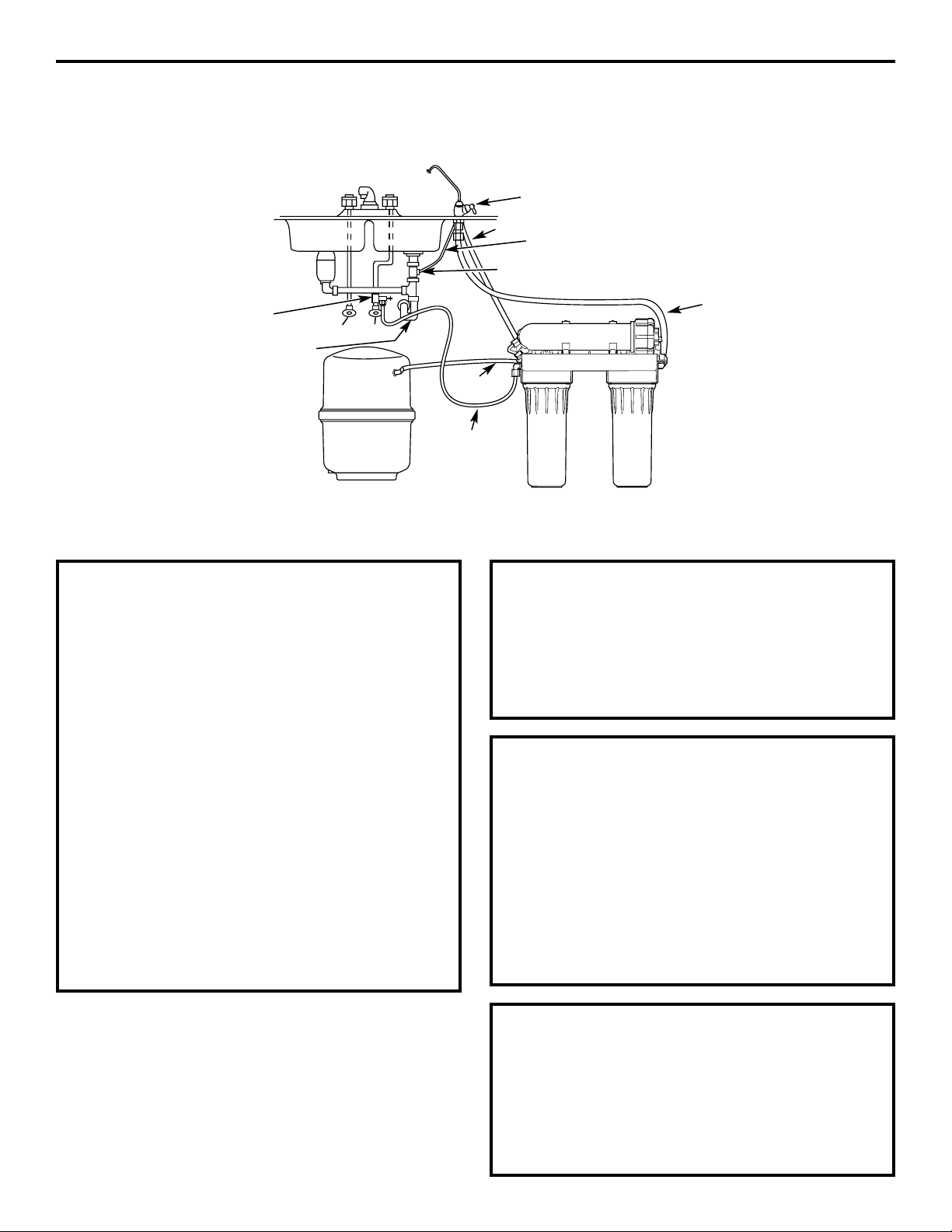
Instrucciones de instalación
Cosas a revisar antes de iniciar la instalación
AGUA DE ALIMENTACIÓN
El suministro de agua hacia el sistema de
Ósmosis Inversa debajo del mostrador debe
tener las condiciones enumeradas en las
especificaciones (vea la sección de Pautas
sobre las especificaciones). Los suministros
de agua locales con frecuencia tendrán estas
condiciones. El agua de pozos puede necesitar
acondicionamiento—haga que el agua sea
analizada por un laboratorio y obtenga sus
recomendaciones para tratamiento.
PRECAUCIÓN: Para aguas con
una dureza mayor a 10 granos (a 6,9 pH), se
recomienda el uso de un descalcificador.
No instalar un descalcificador reducirá la vida
de la membrana del sistema de Ósmosis
Inversa. Consulte la sección de Pautas
sobre las especificaciones para información
adicional sobre la posible necesidad de
un descalcificador.
PUNTO DE DRENAJE
Un punto de drenaje adecuado y un vacío
de aire (consulte los códigos locales) serán
necesarios para el agua rechazada del
cartucho de la membrana del sistema de
Ósmosis Inversa.
INSTALACIÓN EN SÓTANO
Si se va a instalar en un sótano, deje
suficiente tubería en su lugar durante la
instalación para poder mover la unidad hacia
el piso para mayor facilidad en el servicio y
hacer cambios al filtro/membrana. Tubería y
accesorios adicionales se necesitarán.
GRIFO DEL SISTEMA DE OI
El grifo del agua producida por el sistema de
Ósmosis Inversa se instala en el lavaplatos o
en la parte superior del mostrador al lado del
lavaplatos. Con frecuencia se instala en un
orificio existente en el lavaplatos. Se requiere
espacio en la parte de abajo para la tubería
hacia y desde el grifo, y para asegurar el grifo
en su lugar. Todos los conexiones del grifo se
instalan sobre o por encima del lavaplatos o
mostrador. Vea la ilustración arriba.
Tanque de
almacenamiento
Trampa P
del lavaplatos
Agua
caliente
Agua
fría
Adaptador de drenaje
Tubo de drenaje negro de 3/8″
Grifo de agua producida por el sistema de Ósmosis
Inversa montado en el lavaplatos o en el mostrador
Adaptador
del agua de
alimentación
Tubo
amarillo
(entrada)
Tubo
anaranjado
Tubo negro de 1/4″
Tubo azul
(hacia el grifo)
45
Page 46

Instrucciones de instalación
SUMINISTRO DE AGUA DE ALIMENTACIÓN
Revise y cumpla con los códigos locales de plomería al planear, luego instale un accesorio de
suministro de agua de alimentación fría.
A. INSTALACIÓN PREFERIDA
1. Cierre la válvula de suministro de agua
fría debajo del lavaplatos.
2. Destornille el tubo flexible de la válvula
de suministro que se conecta al elevador
del agua FRÍA.
3. Instale el adaptador del agua de
alimentación* que es del diámetro para
ajustarse a la plomería ya sea de 1/2″ ó
3/8″ en su ubicación. NO APRIETE EN
EXCESO.
*Observe la dirección del adaptador del
agua de alimentación y acoplamiento.
Está instalado de forma diferente para
ajustarse a la plomería ya sea de 1/2″
ó 3/8″ en su ubicación.
B. INSTALACIÓN CASERA
OPCIONAL
Donde los códigos lo permitan (Partes
adicionales necesitarán)
*Para tubo metal de 1/2″ DE o más largo
únicamente.
NOTA: Los códigos en el estado de
Massachusetts requieren la instalación por
parte de un plomero certificado y no
permiten el uso de la válvula de montura.
Para la instalación, use el código de plomería
248-CMR de Massachusetts.
La válvula de montura está disponible
a través de Partes y Servicios de GE en el
1.800.626.2002, número de parte WS15X10023.
No se recomiendan las válvulas de monturas
de auto perforación.
1. Apague el suministro de agua fría y anexe
la válvula de montura como se muestra
en la ilustración en la página siguiente.
PELIGRO:
Muchas casas se
conectan electrónicamente a tierra a través
de la plomería. Para protegerse de lesiones
serias o de choques fatales, use únicamente
un taladro manual operado con baterías para
abrir el orificio. NO USE UN TALADRO
ELÉCTRICO.
2. Cierre la válvula de suministro de agua
girando la manija en el sentido del reloj.
46
Para plomería de 3/8 po Para plomería de 1/2 po
Tubería
del grifo
Acoplamiento
Adaptador
Válvula de entrada
Válvula de suministro
de agua fría
Tubería
del grifo
Acoplamiento
Adaptador
Empaque
Empaque
Férula
Válvula
de entrada
Tuerca
Empaque
Page 47

B. INSTALACIÓN CASERA
OPCIONAL
(cont.)
3. Abra la válvula principal de suministro
del agua y varios grifos de la casa para
purgar aire del sistema. Cierre los grifos
cuando el agua corra suavemente.
Acomode la válvula en
el soporte. (NO APRIETE
DEMASIADO)
Deberán verse
algunos filetes
Empaque de caucho
Conexión opcional del suministro de agua (usando
válvula de montura)*
Orificio de 1/4″
previamente abierto
Sello—asegúrese que
el sello está en su lugar
Grapa X
Tuercas (2), no
se requieren si
los orificios en
la grapa tienen
filetes
Válvula de
montura
Manija
Adaptador
del tubo
Arandela
Tuerca de
compresión
Grapa Z
Use para conectar el tubo
*Para tubo metal de 1/2″ DE o más largo
únicamente.
Instrucciones de instalación
C. INSTALACIÓN EN UNA
UBICACIÓN REMOTA
(requiere partes adicionales)
1. Cierre el suministro de agua fría.
2. En cumplimento con los códigos de
plomería, instale un accesorio en la
tubería de agua fría para adaptar un tubo
de 1/4″ DE. En la ilustración abajo se
muestra una conexión típica. Verifique
que se utiliza una válvula de suministro
de agua.
3. Si la unidad de Ósmosis Inversa se va
a instalar a más de 6 pies de la válvula,
reemplace el tubo amarillo con un tubo
GE de mayor longitud de 1/4″. Puede
adquirir una longitud de 33 pies de tubo
de 1/4″ a través de Partes y Servicios de
GE en el 1.800.626.2002, número de parte
WS07X10018. NO REEMPLACE CON
TUBOS DE CALIDAD DESCONOCIDA.
4. Si la unidad de Ósmosis Inversa se va a
instalar a más de 6 pies del grifo, reemplace
el tubo azul con un tubo GE de mayor
longitud de 3/8″. Puede adquirir una longitud
de 33 pies de tubo de 3/8″ a través de Partes
y Servicios de GE en el 1.800.626.2002,
número de parte WS07X10019. Consulte la
sección Instalación del grifo en la página 48
para mayores detalles. NO REEMPLACE CON
TUBOS DE CALIDAD DESCONOCIDA.
Si está utilizando tubos de cobre, NO los
conecte directamente en la unidad de Ósmosis
Inversa. Adquiera un conector y utilice una
longitud corta del tubo amarillo que se
suministra para hacer la conexión final hacia
el sistema de Ósmosis Inversa. No utilice tubos
de cobre para conectar a la máquina de hielos
o al grifo.
Inserto (no incluido)
Tubería
de agua
fría
Tubo de 1/4″ (amarillo)
hacia la entrada
Férula
Válvula de suministro
de agua
Hacia el sistema OI
47
Page 48

Instrucciones de instalación
INSTALACIÓN DEL GRIFO
Asegúrese de que haya espacio debajo
del lavaplatos para hacer las conexiones
necesarias. Seleccione uno de los siguientes
lugares para instalar el grifo:
• En un accesorio existente para rociar, en el
lavaplatos u orificio para dispensar jabón.
• En un orificio a perforarse en la parte superior
del lavaplatos.
• En un orificio a perforarse en el mostrador,
al lado del lavaplatos.
NOTA: Asegúrese de que la base del grifo
quede plana contra la superficie en la
ubicación seleccionada de manera que
el empaque selle.
1. Si es necesario, perfore para hacer un
orificio de 1-1/4″ de diámetro. Cerciórese
de seguir el procedimiento correcto para
perforar porcelana o acero inoxidable.
2. Inserte el pico del grifo en el cuerpo.
Apriete la tapa hasta que esté ajustada.
3. Introduzca el tubo azul, tubo negro de 1/4″
y tubo negro de 3/8″ a través del orificio
en el mostrador o lavaplatos.
4. Introduzca los dos tubos negros a través
del empaque, la base del grifo y el anillo
tórico.
NOTA: Para facilidad de servicio y
mantenimiento, mantenga los tubos de
longitud suficiente de manera que remover el
sistema de Ósmosis Inversa sea posible desde
abajo del lavaplatos.
5. Empuje los tubos negros de 1/4″ y 3/8″
en sus respectivos accesorios serrados
en el cuerpo.
6. Acomode la base y el cuerpo juntos.
Cerciórese de que el anillo tórico y el
empaque estén en su lugar cuando la
base se encuentre con el cuerpo. La
manija del grifo estará en la posición de
las 3 en el reloj con respecto a la base.
7. Deslice la arandela de bloqueo en
el vástago roscado del cuerpo, luego
enrosque la tuerca de latón en el vástago.
Atornille hasta la mitad.
8. Atornille el adaptador del tubo en
el vástago roscado del cuerpo.
9. Empuje el tubo azul en el adaptador. Debe
entrar hasta 1/2″. Hale para cerciorarse de
que está firmemente instalado.
10. Introduzca el tubo y el vástago de nuevo
por el orificio de 1-1/4″.
11. Debajo del mostrador, inserte el disco
de montaje por encima de la arandela de
bloqueo y apriete la tuerca de latón hasta
que esté ajustada.
Disco de
montaje
Base
Tuerca
Manija
Pico
Empaque
Adaptador del tubo
Arandela de bloqueo
Anillo tórico
Ta pa
ENSAMBLADO
Accesorio
serrado de 3/8″
Tubo negro
de 3/8″,
de 27″
de largo
Tubo
negro
de 1/4″
Accesorio serrado
de 1/4″
Adaptador
del tubo
Tubo azul
de 3/8″
Tu er ca
Arandela bloqueo
Cuerpo
Del sistema
de OI
Del sistema
de OI
Hacia el desagüe
48
Page 49

Instrucciones de instalación
INSTALACIÓN DE LA CONEXIÓN DEL DRENAJE
DE FILTRACIÓN
Revise y cumpla con todos los códigos estatales y locales de plomería.
PRECAUCIÓN: Las opciones detalladas a continuación son las ÚNICAS configuraciones
aprobadas para instalación. No use ningún dispositivo de montura de drenaje.
OPCIÓN A: INSTALACIÓN
DE ACCESO AL SÓTANO
Enrute el tubo de drenaje (negro, 1/4″)
DIRECTAMENTE desde el sistema de Ósmosis
Inversa hacia una torre depósito en el sótano,
pasando el vacío de aire provisto en el grifo.
El tubo de drenaje puede también ser enrutado
en el sótano hacia un drenaje del piso o tina
de lavar, siempre y cuando el vacío de aire en
el sótano se mantenga. Evite hundimientos,
vueltas o caídas en el tubo de drenaje. El
vacío del aire del sótano y la configuración de
la instalación del drenaje deberán adaptarse a
todos los códigos locales. Existen accesorios
especiales de vacío del aire para conectar el
tubo de drenaje a la parte superior de la torre
depósito.
Tubo de drenaje del
sistema de Ósmosis
Inversa pasando el
vacío de aire del grifo
Mantener el vacío
de aire en el punto
de drenaje en el
sótano
Tubo negro
de 1/4″
OPCIÓN B: INSTALACIÓN
DEL ADAPTADOR DEL TUBO
DE DRENAJE
PRECAUCIÓN!
NO INSTALE EL ADAPTADOR DEL TUBO
DE DRENAJE HACIA ABAJO DEL
TRITURADOR.
Instale el adaptador del tubo de drenaje que
se suministra debajo del lavaplatos como se
exhibe. El deflector en T suministrado debe
estar en su lugar (adquiera e instale si es
necesario) para evitar una obstrucción en el
tubo de drenaje del sistema de Ósmosis Inversa.
Dirija el tubo de drenaje (negro, 3/8″) desde el
vacío de aire del grifo hacia el adaptador del
tubo de drenaje, verificando que no haya
inclinaciones, curvas o puntos bajos en la línea
que podrían resultar en un tubo de drenaje
obstruido.
El tubo se debe cortar a la longitud para
brindar una línea recta desde el grifo hasta
el drenaje.
El ruido en el drenaje del lavaplatos es normal
mientras el sistema de Ósmosis Inversa está
operando.
49
Adaptador del tubo
de drenaje en línea
diferente al triturador
Agua
caliente
Agua
fría
Triturador
El tubo de drenaje
está recto
Page 50

Instrucciones de instalación
MONTAJE DEL SISTEMA DE ÓSMOSIS INVERSA E
INSTALACIÓN DEL TANQUE DE ALMACENAMIENTO
AHORA QUE SU SISTEMA DE ÓSMOSIS INVERSA ESTÁ
INSTALADO…DESINFECTE!
Desinfecte después de instalar y después
de poner en servicio las partes internas,
incluyendo la reposición del pre-filtro y postfiltro y el cartucho del sistema de Ósmosis
Inversa. Es importante lavarse las manos
con jabón anti-bacterial antes de manipular
las partes internas del sistema. Consulte
la sección Desinfección.
PRECAUCIÓN: Si está instalado
la unidad en una nueva construcción,
asegúrese de que la plomería de la casa
ha sido lavada completamente antes de abrir
la válvula de suministro de agua. También,
antes de desinfectar, asegúrese de retirar
todos los cartuchos según se describe en
la sección Desinfección. El cloro destruirá
el cartucho del sistema de Ósmosis Inversa.
Sostenga la ensambladura del sistema de
Ósmosis Inversa levantada hasta la superficie
de la pared donde se instalará. Marque
la ubicación de los tornillos. Las flechas en
la parte superior del soporte muestran
la ubicación de los orificios de los tornillos.
1
Conecte el tubo al tanque de
almacenamiento: Extienda la longitud
del tubo anaranjado de 3/8″ desde el
accesorio en T de módulo de Ósmosis
Inversa hasta el accesorio en la entrada
del tanque.
5
Se incluyen tornillos para sujetar a una
superficie de madera. Adquiera otros
tornillos según sea necesario.
2
Cuelgue la ensambladura del sistema
de Ósmosis Inversa en los tornillos.
3
Aplique cinta de sellado de rosca de tubos
al accesorio del tanque. Inserte en las
roscas del tanque. Apriete con una llave.
4
Tanque de
almacenamiento
Hacia el grifo
Tubo de suministro
Tubo anaranjado
Espacio mínimo de 2″
para el cambio de cartuchos
TUBO DE DRENAJE DEL GRIFO Y TUBO DE SUMINISTRO DE AGUA
Si OPCIÓN A: INSTALACIÓN DE ACCESO AL SÓTANO (consulte la sección Instalación de la conexión
del drenaje de filtración, página 49) se utilizó, siga con el Paso 2.
Si OPCIÓN B: INSTALACIÓN DEL ADAPTADOR
DEL TUBO DE DRENAJE se utilizó, conecte el
tubo de drenaje del grifo corriendo el tubo
negro de 3/8″ del accesorio serrado del grifo
de 3/8″ al accesorio de drenaje (instalado en
la sección Instalación de la conexión del
drenaje de filtración, página 49). Mantenga la
extensión del tubo tan corta y directa como
sea posible sin curvas, inclinaciones o puntos
bajos. Corte el tubo según sea necesario e
inserte en el accesorio de drenaje.
1
Para conectar el tubo de suministro de
agua: Extienda el tubo amarillo de 1/4″
desde la entrada del sistema de Ósmosis
Inversa hacia el adaptador del agua de
alimentación (vea las ilustraciones en la
sección Suministro de agua de alimentación).
Conecte el tubo según corresponda (consulte
la sección Suministro de agua de alimentación)
y apriete la tuerca firmemente.
2
50
Page 51

Instrucciones de instalación
PROCEDIMIENTO PARA LA REPOSICIÓN DEL PRE-FILTRO,
POST-FILTRO Y CARTUCHO DEL SISTEMA DE ÓSMOSIS
INVERSA, INCLUYENDO DESINFECCIÓN
APAGUE la máquina de hielos (si está
instalada en el sistema
de Ósmosis Inversa).
1
Lave sus manos con jabón anti-bacterial.
2
Cierre el suministro de agua
hacia el sistema de Ósmosis
Inversa.
3
Retire la tapa de la caja protectora del
cartucho del sistema de Ósmosis Inversa
(destornille el tubo
primero, en algunos
modelos). Use alicates
para retirar el cartucho
del sistema de Ósmosis Inversa. Coloque
en una bolsa plástica o deseche si está
reemplazando. Limpie por completo el
interior de la caja protectora y tapa con
papel toalla o cepillo para platos
humedecido con jabón para platos.
Enjuague bien.
6
Abra el grifo del sistema de Ósmosis
Inversa. Drene el tanque (podría tomar
varios minutos). Cierre el grifo del sistema
de Ósmosis Inversa.
PRECAUCIÓN: No cerrar la válvula
de suministro de agua o la válvula de cierre
del tanque causará que el agua se riegue
hacia donde se han retirado los sumideros.
4
Retire los sumideros. Tenga
cuidado—éstos estarán llenos
de agua.
Deseche los filtros. Lave
completamente los sumideros
con jabón para platos. Limpie
completamente el interior de
las cabezas con papel toalla
humedecido con jabón para platos.
Enjuague bien.
5
Reemplace el sumidero de
post-filtro vacío.
7
Llene el sumidero de pre-filtro con agua
hasta a 1″ del anillo tórico. Agregue 2 oz.
(4 cdas.) de cloro casero común. Reemplace
el sumidero de pre-filtro.
8
Abra la válvula de suministro de agua.
Abra el grifo del sistema de Ósmosis
Inversa hasta que el agua empiece a fluir,
luego cierre. Permita que el sistema se llene
por 1 minuto.
9
Abra el grifo y permita que el agua fluya
por 10 minutos. Cierre el grifo por 1
minuto, luego abra y permite que el agua
fluya por 10 minutos, o hasta que el olor
a cloro desaparezca. Cierre el suministro
de agua nuevamente. Drene el sistema
de Ósmosis Inversa.
10
Retire los sumideros. Inserte los
filtros. Lubrique el anillo tórico con
grasa silicona comestible, si es
necesario. (No utilice vaselina).
Apriete los sumideros firmemente.
11
51
Page 52

Instrucciones de instalación
PROCEDIMIENTO PARA LA REPOSICIÓN DEL PRE-FILTRO,
POST-FILTRO Y CARTUCHO DEL SISTEMA DE ÓSMOSIS
INVERSA, INCLUYENDO DESINFECCIÓN (cont.)
Retire la tapa de la caja protectora del
cartucho del sistema de Ósmosis Inversa.
Instale el cartucho del sistema de Ósmosis
Inversa, el extremo del anillo tórico
primero. Lubrique el anillo tórico de la tapa
con grasa silicona comestible, si es
necesario. (NO utilice vaselina). Apriete
la tapa firmemente.
12
Reemplace las baterías en el indicador de
cambio de filtro:
• Utilice un destornillador pequeño
de pala plana o una moneda y con cuidado
abra el compartimiento de baterías.
• Instale la batería CR2032 con el lado (+)
hacia abajo dentro de la bandeja.
• Deslice la bandeja hacia la base y ajuste en
su lugar.
• La luz se prenderá 5 veces de forma
intermitente para indicar la instalación
correcta. Después de 6 meses de uso, la luz
se encenderá nuevamente de forma
intermitente, indicado que es el momento
de reemplazar el filtro. Instale una nueva
batería CR2032 después de 6 meses de uso.
15
Si sólo reemplazó el pre-filtro y el postfiltro, permita que el grifo corra por 5
minutos para retirar partículas inofensivas
de carbono. Si reemplazó el cartucho del
sistema de Ósmosis Inversa, llene y
desocupe el tanque de almacenamiento
tres veces, hasta que el sabor y olor del
preservativo de la membrana comestible
desaparezcan.
16
Una vez que el tanque de almacenamiento
esté lleno, encienda la máquina de hielos.
17
Abra el suministro de agua. Permita que se
llene. (Puede tomar hasta 4 horas). Revise
en busca de fugas.
14
Si reemplazó el cartucho del sistema de
Ósmosis Inversa, también reemplace el
control del flujo y la rejilla. (Destornille el
tubo negro de 1/4″ del accesorio. Retire el
control del flujo con el borde de un cuchillo
limpio. Retire la rejilla con un palillo limpio).
Apriete la tuerca con la mano y luego dé
1/4 de giro con alicates. NO APRIETE
EN EXCESO.
13
52
Control
del flujo
Rejilla
Tuerca de
compresión
Tubo negro
de 1/4″
Page 53

53
Cuidado y limpieza del sistema de Ósmosis Inversa.
www.GEAppliances.com
Para obtener filtros de repuesto, llame sin costo a Repuestos de electrodoméstricos de GE
al 800.626.2002 (EE.UU.), 800.663.6060 (Canadá–inglés), 800.361.3869 (Canadá–francés), o visite
la tienda donde adquirió el sistema de Ósmosis Inversa.
PRECAUCIÓN: Antes de poner en servicio el sistema de Ósmosis Inversa, cierre el
suministro de agua/válvula de montura y abra el grifo de agua del sistema de Ósmosis Inversa. Permita
que el sistema se drene.
Repuesto de cartucho pre-filtro/post-filtro FX12P Bloque de carbono
Repuesto de cartucho del sistema de Ósmosis Inversa FX12M Poliamida de película delgada
Kit de prueba del agua
Para obtener un kit de prueba del agua de un laboratorio independiente, llame a Legend Technical
Services al 1.800.826.8553 ext. 47 y deje sus datos para contactarlo. Ellos le contactarán para
averiguar qué pruebas de agua le interesan, y le informarán sobre el costo de las pruebas. Luego
recibirá un kit que incluye todas las pruebas necesarias para indicar correctamente el nivel de
desempeño de su sistema. El agua del producto se debe someter a prueba como mínimo cada
seis meses.
Servicio al consumidorSolucionar problemasOperaciónSeguridad Instalación
Page 54

Servicio al consumidor Solucionar problemas
Operación SeguridadInstalación
54
Descripción del sistema de Ósmosis Inversa
Pre-filtro—El agua de la tubería de suministro de
agua fría llega al cartucho del pre-filtro, el cual
está dentro del sumidero. El pre-filtro es un
cartucho de sedimentos reemplazable que
contiene carbono activado. El carbono elimina
arena, cieno, tierra, otros sedimentos y hasta
2,0 ppm de cloro del agua de alimentación.
El pre-filtro reduce el cloro en el agua de
alimentación ya que el CLORO DESTRUYE LA
MEMBRANA DEL SISTEMA DE ÓSMOSIS INVERSA.
El agua filtrada, limpia, con cloro reducido fluye
desde el pre-filtro hacia el cartucho del sistema
de Ósmosis Inversa.
Tanque de almacenamiento—El área de
almacenamiento tiene capacidad hasta de
3 galones de agua producida. Un diafragma
al interior del tanque mantiene el agua
presurizada, cuando el tanque está lleno,
para un rápido flujo hacia el grifo cuando se
necesite consumir agua.
Válvula de revisión—Una válvula de revisión está
incorporada en un extremo de la caja del
sistema de Ósmosis Inversa. La válvula de
revisión evita un flujo inverso del agua
producida desde el área de almacenamiento.
Un flujo inverso podría causar que la membrana
del sistema de Ósmosis Inversa se rompiera.
Válvula de apagado automático—Para conservar
el agua, el sistema de agua de consumo tiene
un apagado automático. Cuando el tanque de
almacenamiento ha llenado su capacidad y el
grifo de agua de consumo está cerrado, la
presión cierra el apagado automático. El flujo de
agua hacia la caja del sistema de Ósmosis Inversa
se apaga hasta que el agua de consumo se use
nuevamente y la presión caiga en el sistema de
Ósmosis Inversa.
Sobre el sistema de Ósmosis Inversa.
¿Qué hace el sistema de Ósmosis Inversa?
El sistema de Ósmosis Inversa retira los Sólidos
totales disueltos (TDS–Total Dissolved Solids)
y la materia orgánica del agua al dispersarla a
través de una membrana especial. La membrana
separa los minerales e impurezas del agua y los
expulsa hacia el desagüe. El agua producida de
alta calidad va directamente hacia el grifo de
agua para consumo o hacia el tanque de
almacenamiento. El sistema produce un buen
suministro de agua para consumo cada día.
Consulte las Pautas sobre las especificaciones.
La cantidad que produzca depende
de la presión, temperatura y calidad del
suministro de agua.
El pre-filtro y post-filtro de carbono son cartuchos
reemplazables. El pre-filtro elimina el cloro al
mismo tiempo que filtra los sedimentos.
El post-filtro elimina cualquier otro sabor u
olor no deseados antes de usar el agua.
Sumidero
Sumidero
Cartucho
post-filtro
Cartucho pre-filtro
Tapa de la caja protectora
del sistema de Ósmosis Inversa
Cartucho del sistema
de Ósmosis Inversa
Caja protectora del sistema de Ósmosis Inversa
Gire el sumidero en este
sentido para retirar
Anillo tórico
Anillo tórico
Válvula de apagado
automático
Extremo de anillo tórico
Válvula de revisión
Caja protectora de anillo tórico
Page 55

55
www.GEAppliances.com
Cartucho del sistema Ósmosis Inversa—El
cartucho, al interior de la caja del sistema de
Ósmosis Inversa, incluye una membrana especial
fuertemente envuelta. El agua penetra a través
del cartucho donde la membrana retira los
sólidos disueltos y la materia orgánica. El agua
producida de alta calidad sale de la caja del
sistema de Ósmosis Inversa y se dirige hacia el
tanque de almacenamiento. El agua rechazada,
con los sólidos disueltos y la materia orgánica
sale de la caja y se descarga en el drenaje a través
de un tubo.
Post-filtro—Después de salir del área de
almacenamiento, pero antes de ir hacia el
grifo del sistema, el agua producida va hacia el
post-filtro que se encuentra dentro del sumidero.
El post-filtro es también un cartucho de
sedimento que puede ser reemplazado que
contiene carbono activado. Cualquier sabor,
olor o sedimentos restantes son retirados del
agua producida por el post-filtro. Agua limpia,
de alta calidad, lista para tomar fluye a través del
tubo hacia el grifo del sistema.
Monitor del sistema—Se incluye un temporizador
en la base del grifo para recordarle el momento
de reemplazar el pre-filtro y post-filtro.
Reemplace los filtros cuando la luz azul empiece
a encenderse de forma intermitente para
proteger la membrana del sistema de Ósmosis
Inversa y mantenga el sistema operando
correctamente. Cerciórese de retirar y
reemplazar la batería al mismo tiempo que
reinicializa el temporizador.
Control del flujo—El control del flujo regula el
flujo de agua a través del cartucho del sistema
de Ósmosis Inversa al ritmo requerido para
producir agua de alta calidad. El control está
ubicado en el accesorio de unión en el puerto
de drenaje de la caja del sistema de Ósmosis
Inversa. Una rejilla pequeña en forma de cono
se ajusta al extremo frontal del control del flujo
para evitar la obstrucción debido a sedimentos
en el agua de drenaje. El control del flujo y
la rejilla deberán reemplazarse cada vez que
se cambie el cartucho del sistema de Ósmosis
Inversa.
Servicio al consumidorSolucionar problemasOperaciónSeguridad Instalación
Rejilla
Control del flujo
Tubo negro de 1/4″
(hacia drenaje)
Page 56

Antes de llamar a solicitar servicio…
Problema Posible causas Qué hacer
Sonidos que pueda Fluido de agua desde la unidad • Esto es normal.
escuchar hacia un drenaje.
El agua tiene burbujas Aire en el sistema después de • Desaparecerá después de que el agua corra por
de aire y está turbia la instalación. un tiempo.
Sabor y/u olor a cloro El nivel de ppm de cloro en su
• Si el suministro de agua contiene más de 2,0 ppm de
en el agua producida suministro de agua supera los
cloro, se necesita filtración adicional del suministro de
por el sistema de límites máximos y ha destruido agua hacia el sistema de Ósmosis Inversa. Corrija esta
Ósmosis Inversa la membrana del sistema de condición antes de hacer mantenimiento al sistema
Ósmosis Inversa. de Ósmosis Inversa.
El pre-filtro ya no está retirando • Reemplace el cartucho de la membrana, control
el cloro del suministro de agua. del flujo, rejilla, pre-filtro y post-filtro del sistema
de Ósmosis Inversa.
Otro sabor y/u olor Agua producida de alta calidad • Esto es normal.
puede tener un sabor diferente
al que está acostumbrado.
Bajo uso de agua. • Drene completamente el sistema y permita que se
vuelva a llenar.
Contaminación en almacenamiento •Siga los procedimientos de desinfección.
del agua producida.
El pre-filtro, post-filtro y/o el
• Reponga el pre-filtro y post-filtro. Si el sabor y olor
cartucho deben ser cambiados. persisten, reemplace el cartucho, control del flujo y
rejilla del sistema de Ósmosis Inversa.
Agua goteando del El lado de drenaje del vacío de • Inspeccione y elimine obstrucciones o bloqueos.
orificio del vacío de aire del grifo (tubo de 3/8″) Es importante que no haya hundimientos, vueltas o
aire del grifo está obstruido, restringido o caídas en la línea de drenaje desde el vacío de aire del
incorrectamente conectado grifo hacia la tubería de drenaje. Consulte la sección
hacia el punto de drenaje. Instalación de la conexión del drenaje de filtración para
una
conexión apropiada del drenaje. Si el adaptador
de la línea de drenaje se usó como el punto de drenaje,
se recomienda una inspección/limpieza periódica.
El sistema produce el Esto es normal. • El ritmo de flujo del agua será inferior que el de su
agua muy lentamente llave normal.
El suministro de agua hacia el • Aumente la presión del agua, preacondicione el agua,
sistema Ósmosis Inversa no está etc., según sea necesario para adaptarse antes de
dentro de las especificaciones. hacer mantenimiento el sistema de Ósmosis Inversa.
El cartucho de pre-filtro está •Reemplace el pre-filtro y post-filtro. Si el ritmo no
obstruido con sedimentos aumenta, reemplace el cartucho del sistema de
y/o el cartucho del sistema de Ósmosis Inversa, control del flujo y rejilla.
Ósmosis Inversa está obstruido
con sedimentos.
La luz del grifo El pre-filtro y post-filtro • Reemplace los filtros. No olvide desinfectar el sistema
está intermitente necesitan reposición. al reemplazo de los filtros.
El temporizador no se reinicializó • Retire y reemplace la batería en la base del grifo.
cuando se reemplazaron los filtros.
Han transcurrido seis La batería podría haberse agotado. • Reemplace la batería. NOTA: Reemplazar la batería
meses y la luz del grifo reinicializa el temporizador de seis meses, así que
no está intermitente cerciórese de que reemplaza el pre-filtro y post-filtro
cuando es el momento de hacerlo.
Es posible que la batería se haya • Cada vez que la batería se retire y se vuelva a reinsertar,
retirado recientemente. el temporizador de seis meses empieza nuevamente.
No retire la batería a menos que desee reinicializar
el temporizador.
Consejos para la solución de fallas
¡Ahorre tiempo y dinero! Revise la tabla primero y quizás no necesite
llamar a solicitar un servicio.
Servicio al consumidor Solucionar problemas
Operación SeguridadInstalación
56
Page 57

* NOTA: Los códigos del estado de Massachusetts requieren de instalación por parte
de un plomero certificado y no permiten el uso de válvula de montura. Para la instalación,
use el código de plomería 248-CMR de Massachusetts.
57
Lista de partes.
www.GEAppliances.com
Servicio al consumidorSolucionar problemasOperaciónSeguridad Instalación
Accesorios opcionales
Page 58

58
Catálogo de partes de General Electric.
* NOTA: Los códigos del estado de Massachusetts requieren de instalación por parte
de un plomero certificado y no permiten el uso de válvula de montura. Para la instalación,
use el código de plomería 248-CMR de Massachusetts.
Servicio al consumidor Solucionar problemas
Operación SeguridadInstalación
Para obtener partes de repuesto, llame sin costo al 800.626.2002 (EE.UU.),
800.663.6060 (Canadá–inglés), 800.361.3869 (Canadá–francés).
NO. REF. PARTE NO. DESCRIPCIÓN DE LA PARTE GXRM10GBL
0001 WS15X10037 CUERPO Y PICO DEL GRIFO 1
0002 WS22X10037 CONEXIÓN RÁPIDA DE 3/8″—GRIFO 1
0003 WS22X10005 TUERCA DE 1/4″ 10
0004 WS22X10026 CODO DE TUERCA DE 3/8″ NPT X 1/4″ 2
0005 WS22X10006 INSERTO DE TUBO DE 1/4″ 8
0006 WS22X10038 VÁLVULA—APAGADO AUTOMÁTICO 1
0007 WS22X10039 TUBO EN T DE 1/4″ X 3/8″ X 3/8″ 1
0008 WS22X10008 TUERCA DE 3/8″ 4
0009 WS22X10007 INSERTO DE TUBO DE 3/8″ 4
0010 WS22X10040 VÁLVULA DE REVISIÓN— 1
INSERTO DE 1/4″
0011 WS22X10041 ACCESORIO DE 1/8″ NPT X 1/4″ 1
0012 WS03X10016 CONTROL DEL FLUJO 1
0013 WS03X10015 REJILLA CÓNICA 1
0014 WS22X10002 CODO DE TUERCA DE 3/8″ NPT X 3/8″ 2
0015 FX12M MEMBRANA DEL SISTEMA 1
DE ÓSMOSIS INVERSA
0016 WS03X10045 ANILLO TÓRICO— 1
CAJA PROTECTORA DE MEMBRANA
DEL SISTEMA DE ÓSMOSIS INVERSA
0017 WS31X10025 TAPA—CAJA PROTECTORA 1
DE MEMBRANA DEL SISTEMA
DE ÓSMOSIS INVERSA
0018 WS22X10042 ACCESORIO DE 1/8″ NPT X 1/4″ 1
0019 WS22X10043 CODO—VÁSTAGO DE 1/4″ X 1/4″ 1
0020 WS20X10006 CAJA PROTECTORA DE MEMBRANA 1
DEL SISTEMA DE ÓSMOSIS INVERSA
0021 WS28X10039 SOPORTE 1
0022 WS22X10044 CONECTOR—3/8″ X 3/8″ MNPT 1
0023 WS32X10019 TANQUE DE ALMACENAMIENTO 1
0024 WX5X140 LLAVE INGLESA 1
0025 WS03X10038 ANILLO TÓRICO, CAJA PROTECTORA 2
DEL SUMIDERO
0026 FX12P CARTUCHO DE BLOQUEO 2
DE CARBONO
0027 WS20X10007 CAJA PROTECTORA DEL SUMIDERO 2
0028 WS18X10006 ADAPTADOR DEL TUBO 1
DE DRENAJE—DLA9
0029 WS18X10009 KIT ADAPTADOR— 1
AGUA DE ALIMENTACIÓN
0030 WS10X10028 ENSAMBLAJE DE LA BASE DEL GRIFO 1
0031 WS02X10031 ARANDELA Y TUERCA—GRIFO 1
0033 WS02X10032 TORNILLOS, SOPORTE 8
0034 WS31X10026 CABEZA DE LA CAJA PROTECTORA 2
0035 WS15X10023 VÁLVULA DE MONTURA 1
0036 WS07X10018 TUBO—1/4″ X 33′—BLANCO 1
0037 WS07X10019 TUBO—3/8″ X 33′—BLANCO 1
0038 WS01X10013 TIRAS DE PRUEBA DE NITRATO 1
0039 WS02X10033 TORNILLOS PARA INSTALACIÓN 2
9999 49-50106 MANUAL DEL PROPIETARIO/ 1
INSTRUCCIONES DE INSTALACIÓN
Page 59

59
Notas.
Servicio al consumidorSolucionar problemasOperación
Seguridad
Instalación
Page 60

Servicio al consumidor Solucionar problemas
Operación SeguridadInstalación
Notas.
60
Page 61

61
Notas.
Servicio al consumidorSolucionar problemasOperación
Seguridad
Instalación
Page 62

Garantía del Sistema Ósmosis Inversa
.
Por el período de: GE repondrá:
Un año Cualquier parte del Sistema de Filtración de Ósmosis Inversa cuya falla se deba a
A partir de la fecha un defecto material o de mano de obra. Durante esta garantía limitada de un año, GE
de compra original también ofrecerá sin costo, toda la mano de obra (no incluye el viaje de servicio hasta la
casa) para reemplazar la parte defectuosa. Todo servicio de garantía será proporcionado por
un Proveedor de Servicio GE SmartWater™autorizado.
■ Visitas de servicio hasta su casa para enseñarle cómo
usar el producto.
■ Instalación, entrega o mantenimiento incorrectos.
■ Falla del producto si es abusado, mal utilizado o usado
con un fin diferente al propósito pretendido.
■ Filtros o membranas.
■ Los defectos que resulten de una instalación inapropiada
o daños no causados por GE.
■ La responsabilidad legal de parte de GE bajo esta u otra
garantía por cualquier daño indirecto o consecuencial.
■ Productos que son usados para aplicaciones comerciales
o industriales.
■ Uso de este producto donde el agua sea
microbiológicamente insegura o de calidad desconocida,
sin una desinfección adecuada. Los sistemas certificados
para la reducción de quistes pueden ser usados en agua
desinfectada que puede contener quistes filtrables.
■ La reposición de fusibles caseros o arreglo de
cortocircuitos.
■ Daño al producto causado por accidente, incendio,
inundación o actos de Dios.
■ Daños incidentales o consecuentes causados por posibles
defectos con este aparato.
■ Daños causados después de la entrega.
Qué no cubrirá GE:
Esta garantía se extiende al comprador original y a cualquier propietario posterior de productos adquiridos para uso casero
dentro de los EE.UU. En Alaska, la garantía excluye el costo de envío o llamadas de servicio a su casa.
Algunos estados no permiten la exclusión o límite de daños incidentales o consecuentes. Esta garantía le concede sus
derechos legales específicos, y también puede tener otros derechos que varían de estado a estado. Para conocer cuáles son
sus derechos legales, consulte a su oficina local o estatal de asuntos del cliente o a la Procuraduría de su estado.
ESTA GARANTÍA REEMPLAZA CUALQUIER OTRA GARANTÍA, EXPRESA O IMPLICADA, INCLUYENDO LAS
GARANTÍAS DE COMERCIALIZACIÓN O PROPIEDAD PARA UN PROPÓSITO PARTICULAR.
Garante: General Electric Company. Louisville, KY 40225
Servicio al consumidor Solucionar problemas
Operación SeguridadInstalación
62
Todo servicio de garantía será proporcionado por un Proveedor
de Servicio GE SmartWater
™
autorizado. Para concertar una cita
en línea, visítenos 24 horas al día a www.GEAppliances.com, o
llámenos gratuitamente al 800.GE.CARES (U.S.) o al 866.777.7627
(Canadá).
Grape aquí su recibo.
Se requiere facilitar prueba de
la fecha de compra original para
obtener un servicio bajo
la garantía.
Page 63

63
Soporte al consumidor.
Página Web de GE Appliances
www.GEAppliances.com
¿Tiene alguna pregunta sobre su electrodoméstico? ¡Pruebe la página Web de GE Appliances 24 horas al
día, cualquier día del año! Para mayor conveniencia y servicio más rápido, ya puede descargar los Manuales
de los Propietarios, pedir piezas o incluso hacer una cita en línea para que vengan a realizar una
reparación. También puede “Ask Our Team of Experts ™ ” (Preguntar a nuestro equipo de expertos) sobre
cualquier cuestión y mucho más...
Solicite una reparación www.GEAppliances.com
El servicio de expertos GE está a tan sólo un paso de su puerta. ¡Entre en línea y solicite su reparación
cuando le venga bien 24 horas al día cualquier día del año! O llame al 800.GE.CARES (800.432.2737)
durante horas normales de oficina.
Real Life Design Studio (Estudio de diseño para la vida real)
www.GEAppliances.com
GE apoya el concepto de Diseño Universal—productos, servicios y ambientes que pueden usar gente de
todas las edades, tamaños y capacidades. Reconocemos la necesidad de diseñar para una gran gama de
habilidades y dificultades físicas y mentales. Para más detalles cobre las aplicaciones de GE Diseño Universal,
incluyendo ideas de diseño para la cocina para personas con discapacidades, mire nuestra página Web hoy
mismo. Para personas con dificultades auditivas, favor de llamar al 800.TDD.GEAC (800.833.4322).
Garantías ampliadas www.GEAppliances.com
Compre una garantía ampliada y obtenga detalles sobre descuentos especiales disponibles mientras su
garantía está aún activa. Puede comprarla en línea en cualquier momento, o llamar al (800.626.2224)
durante horas normales de oficina. GE Consumer Home Services estará aún ahí cuando su garantía termine.
Piezas y accesorios www.GEAppliances.com
Aquellos individuos con la calificación necesaria para reparar sus propios electrodomésticos pueden
pedir que se les manden las piezas o accesorios directamente a sus hogares (aceptamos las tarjetas
VISA, MasterCard y Discover). Haga su pedido en línea hoy, 24 horas cada día o llamar por teléfono
al 800.626.2002 durante horas normales de oficina.
Las instrucciones descritas en este manual cubren los procedimientos a seguir por cualquier usuario. Cualquier
otra reparación debería, por regla general, referirse a personal calificado autorizado. Debe ejercerse precaución
ya que las reparaciones incorrectas pueden causar condiciones de funcionamiento inseguras.
Póngase en contacto con nosotros www.GEAppliances.com
Si no está satisfecho con el servicio que recibe de GE, póngase en contacto con nosotros en nuestra página
Web indicando todos los detalles así como su número de teléfono o escríbanos a:
General Manager, Customer Relations
GE Appliances, Appliance Park
Louisville, KY 40225
Registre su electrodoméstico www.GEAppliances.com
¡Registre su nuevo electrodoméstico en línea—cuando usted prefiera! El registrar su producto a tiempo le
proporcionará, si surgiera la necesidad, una mejor comunicación y un servicio más rápido bajo los términos
de su garantía. También puede enviar su tarjeta de registro pre-impresa que se incluye en el material de
embalaje o recorte y use el formulario de este Manual del Propietario.
Page 64

Consumer Support.
GE Appliances Website
In the U.S.: www.GEAppliances.com
Have a question or need assistance with your appliance? Try the GE Appliances Website 24 hours a day,
any day of the year! For greater convenience and faster service, you can now download Owner’s Manuals,
order parts, catalogs, or even schedule service on-line. You can also “Ask Our Team of Experts™” your questions,
and so much more... In Canada: www.geappliances.ca
Schedule Service In the U.S.: www.GEAppliances.com
Expert GE repair service is only one step away from your door. Get on-line and schedule your service at your
convenience 24 hours any day of the year! Or call 800.GE.CARES (800.432.2737) during normal business hours.
In Canada, call 1.800.361.3400
Real Life Design Studio In the U.S.: www.GEAppliances.com
GE supports the Universal Design concept—products, services and environments that can be used by people of all
ages, sizes and capabilities. We recognize the need to design for a wide range of physical and mental abilities and
impairments. For details of GE’s Universal Design applications, including kitchen design ideas for people with
disabilities, check out our Website today. For the hearing impaired, please call 800.TDD.GEAC (800.833.4322).
In Canada, contact: Manager, Consumer Relations, Camco, Inc.
Suite 310, 1 Factory Lane
Moncton, N.B. E1C 9M3
Extended Warranties In the U.S.: www.GEAppliances.com
Purchase a GE extended warranty and learn about special discounts that are available while your warranty is still
in effect. You can purchase it on-line anytime, or call 800.626.2224 during normal business hours. GE Consumer
Home Services will still be there after your warranty expires. In Canada, call 1.888.261.2133
Parts and Accessories In the U.S.: www.GEAppliances.com
Individuals qualified to service their own appliances can have parts or accessories sent directly to their homes
(VISA, MasterCard and Discover cards are accepted). Order on-line today, 24 hours every day or by phone at
800.626.2002 during normal business hours.
Instructions contained in this manual cover procedures to be performed by any user. Other servicing generally should be
referred to qualified service personnel. Caution must be exercised, since improper servicing may cause unsafe operation.
Customers in Canada should consult the yellow pages for the nearest Camco service center, or call 1.888.261.3055.
Contact Us In the U.S.: www.GEAppliances.com
If you are not satisfied with the service you receive from GE, contact us on our Website with all the details
including your phone number, or write to: General Manager, Customer Relations
GE Appliances, Appliance Park
Louisville, KY 40225
In Canada: www.geappliances.ca, or write to: Director, Consumer Relations, Camco, Inc.
Suite 310, 1 Factory Lane
Moncton, N.B. E1C 9M3
Register Your Appliance In the U.S.: www.GEAppliances.com
Register your new appliance on-line—at your convenience! Timely product registration will allow for enhanced
communication and prompt service under the terms of your warranty, should the need arise. You may also mail in
the pre-printed registration card included in the packing material, or detach and use the form in this Owner’s
Manual. In Canada: www.geappliances.ca
Printed in China
 Loading...