

Page 1
General Electric Company
Appliance Park, Louisville, KY40225
Water Softening
System............................1
Owner’s Manual & installation instructions
Model GXOF18K
Sistema Suavizante
de Agua..........................21
Manual del Propietario e Instrucciones de Instalación
Modelos GXOF18K
Waterverzachter
Systeem..........................44
Gebruikers en Installatie Handleiding
Model GXOF18K
Système Adoucisseur
D’eau..............................65
Manuel du Proprietaire et Directives D’Installation.
Model GXOF18K
7310993 Rev B
Page 2
Water Softening
system
Safety Information . . . . . . . . . .2
Installation Instructions . .3–10
Step-by-step instructions . . .6–10
Operating Instructions
Breaking a salt bridge . . . . . . .12
Cleaning the nozzle and
venturi assembly . . . . . . . . . . .12
Features . . . . . . . . . . . . . . . . . .13
Service . . . . . . . . . . . . .11, 14–16
Water softener system . . . .11–16
Care and Cleaning . . . . . . . .17
Troubleshooting Tips . . . .18–20
Consumer Support
Parts list . . . . . . . . . . . . . . . . . . 87
www.GEAppliances.com
#30500 General GXOF18K Euro Version 10-01
Write the model and serial numbers here:
Model # ____________________________
Serial # ____________________________
To find these numbers, lift the cover and
look on the rim below the control panel.
GXOF18K
Owner’s Manual &
Installation Instructions
System tested and certified by NSF International against
NSF/ANSI Standard 44 for softener performance
and the reduction of barium and radium 226/228.
Page 3
IMPORTANT SAFETY INFORMATION.
READ ALL INSTRUCTIONS BEFORE USING.
SAFETY PRECAUTIONS
■ Check and comply with your state and local
codes. You must follow these guidelines.
■ Use care when handling the water softening
system. Do not turn upside down, drop, drag
or set on sharp protrusions.
■ Water softening systems using sodium chloride
(salt) for recharge add sodium to the water.
Persons on sodium restricted diets should consider
the added sodium as part of their overall intake.
Potassium chloride can be used as an alternative to
sodium chloride in your softener.
■
The water softening system works on 24 volt-50 Hz
electrical power only. Be sure to use only the
included transformer.
■ Transformer must be plugged into an indoor
220 - 240 volt, grounded outlet only.
■ Use clean water softening salts only, at least
99.5% pure. NUGGET, PELLET or coarse
SOLAR salts are recommended. Do not use rock,
block, granulated or ice cream making salts.
They contain dirt and sediments, or mush and
cake, and will create maintenance problems.
■ Keep the salt hole cover in place on the softener
unless servicing the unit or refilling with salt.
WARNING:Do not use with water that is
microbiologically unsafe or of unknown quality
without adequate disinfection before or after
the system.
READ AND FOLLOW THIS SAFETY INFORMATION CAREFULLY.
SAVE THESE INSTRUCTIONS
PROPER INSTALLATION
■ Install or store where it will not be exposed to
temperatures below freezing or exposed to any
type of weather. Water freezing in the system will
break it. Do not attempt to treat water over 37°C.
■ Do not install in direct sunlight. Excessive sun or
heat may cause distortion or other damage to
non-metallic parts.
■ Properly ground to conform with all governing
codes and ordinances.
■ Use only lead-free solder and flux for all sweat-
solder connections, as required by state and
federal codes.
■
The water softening system requires a minimum
water flow of 11 litres per minute at the inlet.
Maximum allowable inlet water pressure is 8.6 Bar.
If daytime pressure is over 5.5 Bar, nighttime
pressure may exceed the maximum. Use a pressure
reducing valve to reduce the flow if necessary.
■
Softener resins may degrade in the presence of
chlorine above 1 ppm. If you have chlorine in
excess of this amount, you may experience
reduced life of the resin. In these conditions,
you may wish to consider purchasing a GE
point-of-entry household filtration system with
a chlorine reducing filter.
WARNING:Discard all unused parts
and packaging material after installation.
Small parts remaining after the installation
could be a choke hazard.
This water softening system must be properly installed and located in accordance with the Installation
Instructions before it is used.
2
For your safety, the information in this manual must be followed to minimize the risk of electric shock,
property damage or personal injury.
WARNING!
Page 4
3
CAUTION: Certain plumbing skills are needed for installation. If you are unsure about
any part of the installation of this product, consult a professional plumber.
Installation instructions.
Unpacking and Inspection
Be sure to check the entire softener for any
shipping damage or parts loss. Also note
damage to the shipping cartons. Contact the
transportation company for all damage and
loss claims. The manufacturer is not
responsible for damages in transit.
Small parts needed to install the softener are
packaged either in a bag or on a cardboard
sheet. To avoid loss of the small parts, keep
them packaged until you are ready to use them.
Be sure not to discard components hidden in
packaging.
■ Before you begin installation, read these
Installation Instructions completely. Then,
obtain all the materials and tools you will
need to make the installation. Failure to
properly install the softener voids the
warranty.
■ Check local codes. The installation must
conform to them.
■ Consult with your licend local plumber, if
you have questions on the Plumbing Code
■ Use only lead-free solder and flux for all
sweat-solder connections, as required by
state and federal codes.
■ Connect the softener to the main water
supply pipe before or ahead of the water
heater. DO NOT RUN HOT WATER THROUGH
THE SOFTENER. Temperature of water
passing through the softener must be
less than 49°C.
■ Use care when handling the softener.
Do not turn upside down, drop, drag
or set on sharp protrusions.
■ Maximum allowable inlet water pressure is
8.6 Bar. If daytime pressure is over 5.5 Bar,
nighttime pressure may exceed the
maximum. Use a pressure reducing valve
if necessary. (Adding a pressure reducing
valve may reduce the flow.)
■ The softener works on 24 volt-50 Hz
electrical power only. Be sure to use the
included transformer. Be sure the electric
outlet and transformer are in an inside
location to protect from moisture.
■ See Where to Install the Softener section for
more details.
WARNING:Do not use with water
that is microbiologically unsafe or of
unknown quality without adequate
disinfection before or after the system.
The water should be tested periodically
to verify that the system is performing
satisfactorily.
■ Small parts remaining after the installation
could be a choke hazard. Discard safely.
Important Installation Recommendations
Read entire manual. Failure to follow all guidelines and rules could cause personal injury or
property damage.
Page 5
4
Installation instructions.
Plan How You Will Install the Softener
You must first decide how to run in and out
pipes to the softener. Look at the house
main water pipe at the point where you will
connect the softener. Is the pipe soldered
copper, glued plastic, or threaded galvanized?
What is the pipe size?
WARNING: Use only lead-free
solder and flux to prevent lead poisoning.
See Typical Installation Illustration, Fig. 1. Use
this as a guide when planning your particular
installation. Be sure to direct the incoming hard
water supply to the softener valve inlet fitting.
The valve is marked IN and OUT. See illustration
on page 5 to help you prepare.
Where to Install the Softener
■ Place the softener as close as possible to a
sewer drain, or other acceptable drain point
or standpipe.
■ It is recommended to keep outside faucets
on hard water to save soft water and salt.
■
Do not install the softener in a place where it
could freeze. Freeze damage is not covered by
the warranty.
■ Do not install the softener where it would
block access to the water heater or access to
the main water shutoff.
■ Put the softener in a place where water
damage is least likely to occur if a leak
develops. The manufacturer will not repair
or pay for water damage.
■ A 220 - 240-volt electric outlet is needed to plug
in the included transformer. The softener
has a 2 m power cable. If the outlet is
remote (up to 30 meters), use 0.8 mm2 wire
to connect. Be sure the electric outlet and
transformer are in an inside location, to protect
from wet weather. Be sure the outlet is
unswitched to prevent accidental shutoff.
■ If installing in an outside location, you must
take the steps necessary to assure the softener,
installation plumbing, wiring, etc., are as
well protected from the elements (sunlight,
rain, wind, heat, cold), contamination,
vandalism, etc., as when installed indoors.
Outdoor installation is not recommended, and
voids the warranty.
■ Keep the softener out of direct sunlight.
The sun’s heat may distort non-metallic
parts and may damage the electronics.
■ In and out fittings included with the softener
are 1″ .
You should maintain the same, or larger,
pipe size as the water supply pipe, up to the
softener inlet and outlet.
■ Use the included bypass valve to install the
softener. The bypass valve allows you to turn
off water to the softener for servicing, but
still have water in the house pipes.
■ Use copper, brass or galvanized pipe and
fittings. Some codes may also allow CPVC
plastic pipes.
■ If additional drain hose is needed for valve
and salt tank drains, it can be ordered from
GE Parts.
■ If a rigid valve drain is needed to comply
with plumbing codes, you can buy the parts
needed to connect a 1/2″ copper tubing or
plastic pipe drain.
■ Clean nugget or pellet water softener salt is
needed to fill the brine tank, see Step 8 in
the Step-by-Step Installation Instructions.
Tools and Materials Required for Installation
Page 6

5
Typical Installation Illustration
Soft water
Hard water to
outside faucets
MAIN WATER PIPE
Hard water
NOTE: See Drain Hose Connections section.
24V transformer
220 -240 volt outlet
Bypass valve
Hard water to
outside faucets
Inlet valve
Outlet valve
3-Valve Bypass System
For soft water service:
• Open the inlet and
outlet valves
• Close the bypass valve
For bypass hard water:
• Close the inlet and
outlet valves
• Open the bypass valve
SALT
GOES HERE
Brinewell
INLET
Washer (2) (not supplied)
Copper tube, 3/4″ (2) (not supplied)
Installation nut (2) (not supplied)
Bypass Valve
• Pull out for soft water service
• Push in for bypass
Nut (2) (not supplied)
Copper tube, 3/4″ (2) (not supplied)
Washer (2) (not supplied)
Installation adapter (2) (see above)
INLET
Union (not supplied) (2)
Optional 3-Valve Bypass Installation Illustration
Adapters for this installation are not supplied with the softener.
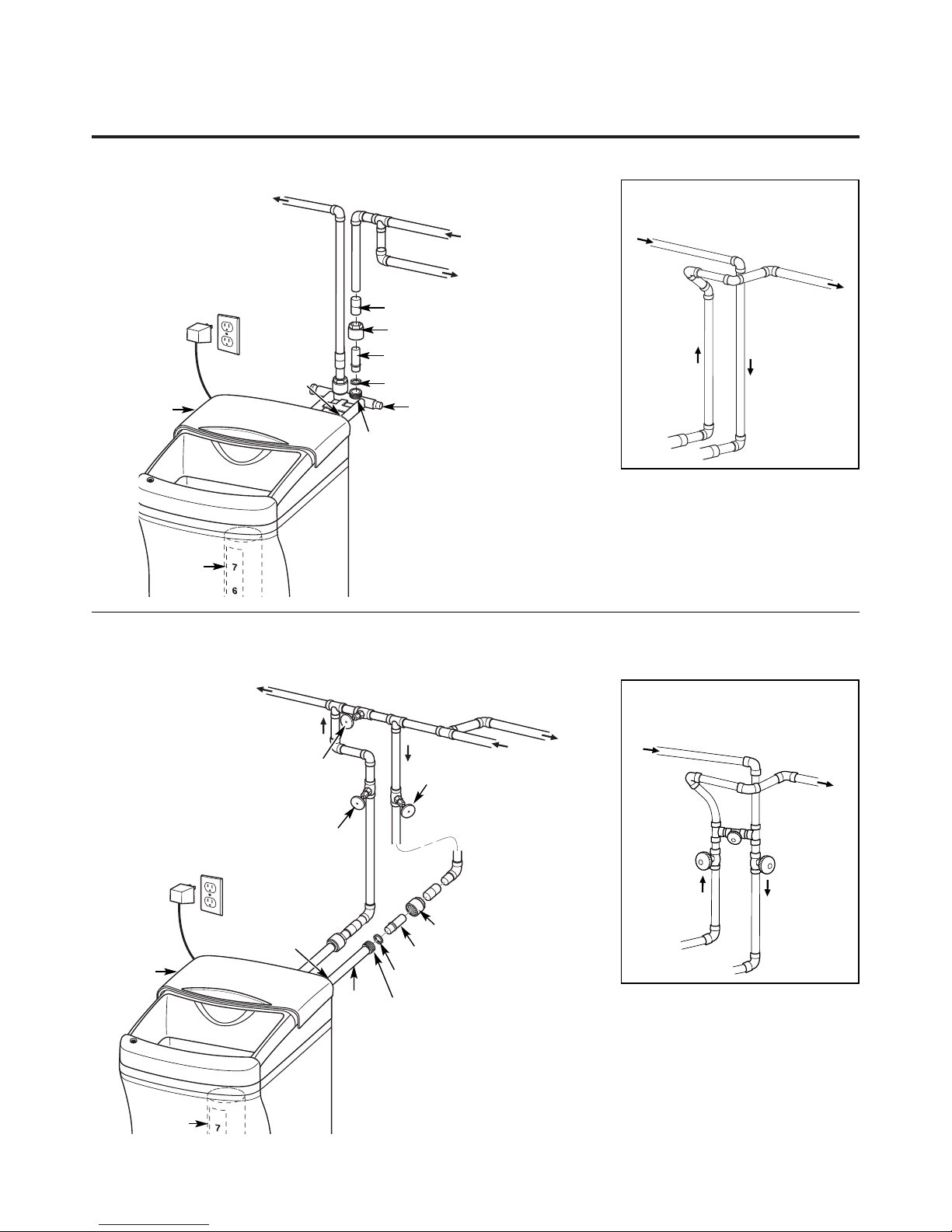
Fig. 1
CROSSOVER
Use if water supply flows from the left.
Include single or 3-valve bypass.
Hard water
From softener
outlet
Soft water
To softener
inlet
Fig. 2
CROSSOVER
Use if water supply flows from the left.
Include single or 3-valve bypass.
Hard water
From softener
outlet
Soft water
To softener
inlet
MAIN WATER PIPE
Hard water
Soft water
220 - 240 volt outlet
24V
transformer
Brinewell
SALT
GOES HERE
Drain
(not shown)
Drain
(not shown)
Salt hole
cover
Salt hole
cover
Page 7
6
Step-by-step installation instructions.
■ Turn off the gas or electric supply to the water heater, in the possibility that
the water heater may be drained while draining pipes.
■
Turn off the water supply to pipes to be cut and drain the house water pipes.
■
Open both hot and cold faucets at the lowest location possible
.
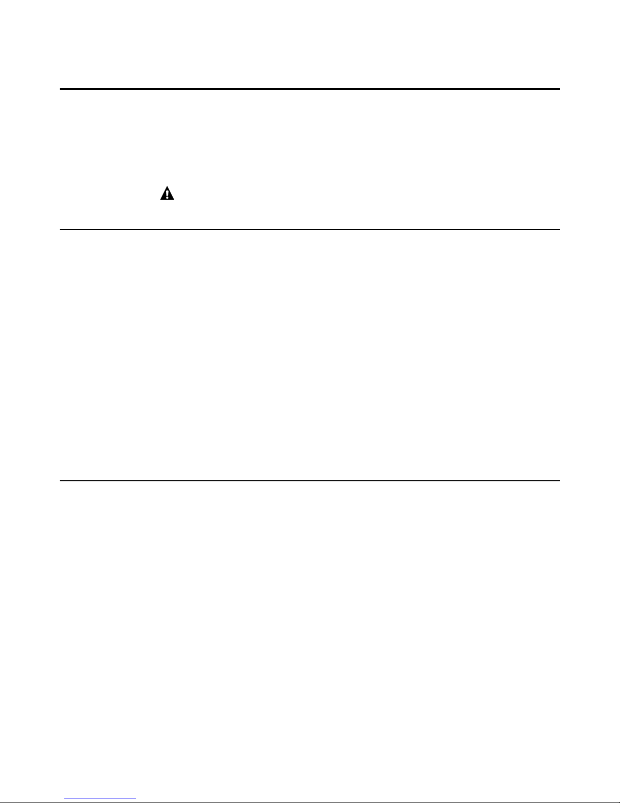
NOTE:
For easier installation, remove the top cover (Figure 3).
cover forward and lift up.
1. INSTALL BYPASS VALVE ( Actual bypass may differ from drawing)
• Remove top cover (fi gure 3) and remove plastic shipping plug and wire from valve outlet .
• Push the bypass valve (lubricate o-ring seals with silicone grease) into both ports of the
valve as shown in Fig. 3A.
• Snap the 2 large plastic clips in place, from the top, down as shown in Figures 3A and 3B.
Be sure they snap into place. Pull on the bypass valve to make sure it is held securely in place.
Make sure to read the the hardness bleed screw settings on page 91 of this manual
2. MOVE THE SOFTENER ASSEMBLY INTO INSTALLATION POSITION
Be sure the installation surface is level and smooth. Sharp objects under the tank may
puncture it. If needed, place the tank on a section of 2 cm thick (minimum) plywood.
Then, place shims under the plywood as needed to level the softener.
3. PLUMB “IN” AND “OUT” PIPES TO AND FROM SOFTENER
CAUTION:
Observe all of the following cautions as you connect inlet and
outlet plumbing. See illustrations on page 5.
• BE SURE INCOMING HARD WATER SUPPLY IS DIRECTED TO THE SOFTENER
VALVE INLET PORT. If house water fl ow is from the left, use a plumbing crossover as
shown in Fig. 1, page 5. If house water fl ows up from the fl oor level, turn the bypass valve
upside down as shown in Fig. 3C.
• If making a soldered copper installation, do all sweat soldering before connecting pipes
to the bypass valve. Torch heat will damage plastic parts.
• When turning threaded pipe fi ttings onto plastic fi ttings, use care not to
cross-thread.
• Use pipe joint compound on all external pipe threads.
• Support inlet and outlet plumbing in some manner (use pipe hangers) to keep the
weight off of the valve fi ttings.
4. CONNECT AND RUN THE VALVE DRAIN HOSE
IMPORTANT: If you want to attach the drain fi tting to a rigid tube, see Step 4A .
• Assemble drain fi tting as shown in Fig. 4.
• Use the provided drain hose to attach to the valve drain fi tting. To keep water
pressure from blowing the hose off, use a hose clamp to secure in place. Cut
the necessary length and use the remainder in Step 5.
• Locate the other end of the hose at a suitable drain point (fl oor drain, sump, laundry
tub, etc.) that terminates at the sewer. Check and comply with local codes.
IMPORTANT: If more drain hose is needed, it should be ordered from GE Parts.
The water softener will not work if water cannot exit this hose during
recharge.
• Tie or wire the hose in place at the drain point. High water pressure will cause it to whip
during the back-wash and fast rinse cycles of recharge. Also provide an air gap of at least
4cm between the end of the hose and the drain point. An air gap prevents possible
siphoning of sewer water into the softener, if the sewer should “back-up.”
• If raising the drain hose overhead is required to get to the drain point, do not raise
higher than 2 m above the fl oor. Elevating the hose may cause a back-pressure that could
reduce brine draw during recharge.
Page 8
8. ADD WATER AND SALT TO THE BRINE TANK
• Lift the salt hole cover. Add about 11 litres of water into the
tank. Do not add into the brinewell.
• Fill tank with NUGGET, PELLET or coarse SOLAR water softener
salt with a purity of 99.5% or higher. Do not use rock, block,
granulated and ice cream-making salts, or salt with iron-removing
additives
Maximum salt storage capacity is approxilately 45Kg.
Keep the salt hole cover closed unless servicing the unit or
refi lling with salt.
NOTE: If the softener is installed in a humid basement or other damp
area, it is better to fi ll the tank with less salt, more frequently. 25 Kg.
of salt will last for several months, depending on water hardness,
family size and water softening system model.
9. CONNECT TO ELECTRICAL POWER
To gain access to the transformer/power cord assembly, remove the
salt hole cover from the softener. Unclip the tabs on the rear of the
top cover and rotate the cover upwards to remove. DO NOT PULL
OR DISCONNECT WIRING.
• The softener works on 24 volt-50Hz electric power. The included
transformer changes standard 220 - 240 -volt AC house power to
24 volts.
Plug the transformer into a 220 - 240-volt outlet only. Be sure the
outlet is always live so it can not be switched off by mistake.
• Replace the top cover.
• Replace the salt hole cover.
7
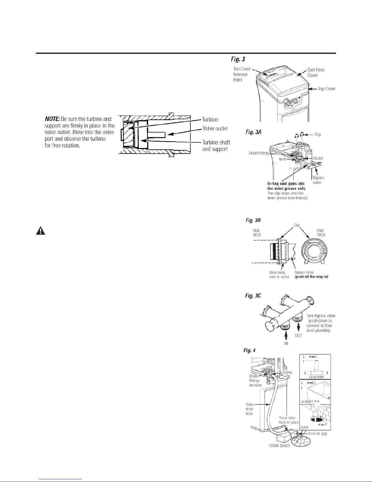
4A. CONNECTING A RIGID VALVE DRAIN TUBE
To adapt a copper drain tube to the softener, buy a compression fi tting (garden hose thread x
1/2” O.D. tube) and needed tubing from your local hardware store.
5. INSTALL THE BRINE TANK OVERFLOW FITTINGS AND HOSE
• Insert the rubber grommet into the 2 cm diameter hole in the brine tank sidewall as shown
in Fig. 5.
• Push the end of the hose adapter elbow into the grommet as shown in Fig. 5.
• Attach a length of hose (use remaining hose from Step 4) to the hose adapter elbow. Use a hose
clamp to hold it in place.
• Locate the other end of the hose at the drain point. DO NOT ELEVATE this hose higher than
the elbow on the brine tank.
IMPORTANT: DO NOT TEE OVERFLOW HOSE TO VALVE DRAIN HOSE.
NOTE: This drain is for safety only. If the cabinet (brine tank) should over-fi ll with water, the excess
is carried to the drain.
6. INSTALL GROUNDING CLAMP (not included)
DANGER:
Failure to properly attach ground clamp could result in electrical shock.
If plumbing is metal, to maintain electrical ground continuity in the house cold water piping, install
the ground clamp (not included) as shown in Fig. 6.
• Clean pipe with emery paper in the area where the clamp is to be installed.
• Install grounding clamps as shown, making sure clamps fi t freely around pipe.
• Make sure lock washer is in place.
• Handtighten screw, then one more full turn with screwdriver.
NOTE: When replacing an existing softener, also replace grounding clamps.
If removing softener completely, hard-plumb the water line with same type of pipes as the original
to assure plumbing integrity and ground continuity over the life of the home.
7. FLUSH PIPES, EXPEL AIR FROM SOFTENER, AND TEST YOUR INSTALLATION FOR
WATER LEAKS
CAUTION:
To avoid water or air pressure damage to softener inner parts, be sure to
do the following steps in exact order.
• Fully open 2 cold soft water faucets nearby the softener.
• Place bypass valve in “bypass” position by pushing the stem inward.
• Fully open the house main water pipe shutoff valve. Observe a steady fl ow from both faucets
opened in step A, above.
• Place bypass valve in the “service” position EXACTLY as follows. KEEP SOFT WATER
FAUCETS OPEN.
• SLOWLY pull or slide the valve stem (out) toward the service position, pausing several times to
allow the softener to pressurize slowly.
• After about 3 minutes, open a HOT water faucet for 1 minute, or until all air is expelled, then
close. NOTE: If water appears cloudy or has salty taste, allow to run for several more minutes, or
until clear.
• Close all water faucets.
• Check your plumbing work for leaks and fi x right away if any are found. Be sure to observe
previous caution notes.
• Turn on the gas or electric supply to the water heater. Light the pilot, if applicable.
Page 9

8
Step-by-step installation instructions.
Programming the Control
CONTROL SETTINGS REQUIRED upon installation and after an
extended power outage.
NOTES:
■ WHEN THE TRANSFORMER IS PLUGGED INTO THE
ELECTRICAL OUTLET, 12:00 PM (flashing), and an arrow is
displayed next to PRESENT TIME on the faceplate decal. The blue
indicator light will also flash. Program the control as instructed
below.
■ If - - - is flashing, use the UP button to set the correct code
F18 for GXOF18K
If you pass by the correct number, use the DOWN button. Then
press the MODE button to accept the correct model.
■ A “beep” sounds while pressing buttons for control programming.
One beep signals a change in the control display. Repeated beeps
mean the control will not accept a change from the button you
have pressed, and you should select another button.
■ To program the control, you will use the UP , DOWN and
MODE buttons.
■ Use the MODEbutton to scroll arrow to desired control function.
SET PRESENT TIME OF DAY
1. Press the MODE button until arrow
points to PRESENT TIME.
2. Press UP or DOWN button
to set. The UP button advances the time; the DOWN button moves
the time in reverse.
2. If the present time is between noon and midnight, be sure PM shows
in the display. If the present time is between midnight and noon, be
sure AM shows in the display.
NOTE: Each press of an UP or DOWN button changes the time
by one minute. Holding the button changes the time at a rapid rate.
3. When the present time is correct, press MODE to accept.
SET WATER HARDNESS NUMBER
1. Press the MODE button until
arrow points to HARDNESS.
2. Press UP or DOWN button to
set your water hardness number in the display. DOWN decreases the
hardness value. UP increases the hardness value.
NOTE: Each press of a button changes the display by 1, between 1 and
25. Above 25, the display changes 5 at a time (25, 30, 35, etc.). Holding
a button in changes the numbers at a rapid rate.
3. When the display shows your water hardness (in grains per gallon),
press MODE to accept.
NOTE: If there is clear water iron in your water supply, you will need to
increase the hardness setting by 5 for each 1 ppm of clear water iron in
your water supply.
You can get the grains per gallon (gpg) hardness of your
water supply from a water analysis laboratory. If you are on
a municipal supply, call your local water department. To calculate the
gpg hardness from German degrees divide by 0.953, to calculate gpg
hardness from French degrees divide by 1.71. If your report
shows hardness in parts per million (ppm) or milligrams per liter
(mg/l), simply divide by 17.1 to get the equivalent number of grains
per gallon.
SET RECHARGE (STARTING) TIME
1. Press the MODE button until arrow
points to RECHARGE TIME.
NOTE: A flashing 2:00 AM (factory
default) should show in the display. This is a good time for recharge to
start (takes about 2 hours) in most households because water is not in
use. HARD WATER is bypassed to house faucets during recharge.
If no change is needed, go to step 3. To change the recharge starting
time, follow step 2.
2. Press UP or DOWN button to set the desired recharge start
time. Be sure to observe the AM or PM as you did when setting the
time of day.
NOTE: Each press of a button changes the time by 1 hour. Holding the
buttons in changes the time at a rapid rate.
3. Press the MODE button to accept.
SET SALT LEVEL
1. Press the MODE button until
arrow points to SALT LEVEL.
2. Determine level of salt in brine tank
using yellow indicator on side of brine well, inside brine tank
(see illustration on page 5).
3. Press UP or DOWN button to
set the SALT LEVEL to correspond to
level on yellow indicator in brine tank.
NOTE: Each press of a button changes the
level by increments of 0.5 up to 8.0. As the number increases, the salt
level bars increase on each whole number. Lowering the salt level
below zero turns the SALT LEVEL indicator OFF.
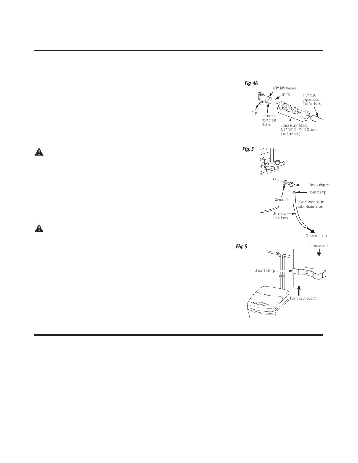
4. Press the MODE button to accept. The display
shows the present time of day and DAYS TO
EMPTY. RECHARGE TONIGHT may appear if
unit is new.
SALT
LEVEL
PM
SALT
LEVEL
SALT
LEVEL
DAYS TO EMPTY
PM
RECHARGE TONIGHT
E
SALT
LEVEL
SALT
LEVEL
AM
SALT
LEVEL
Page 10
9
Optional Control Settings
The controller display has several options and features.
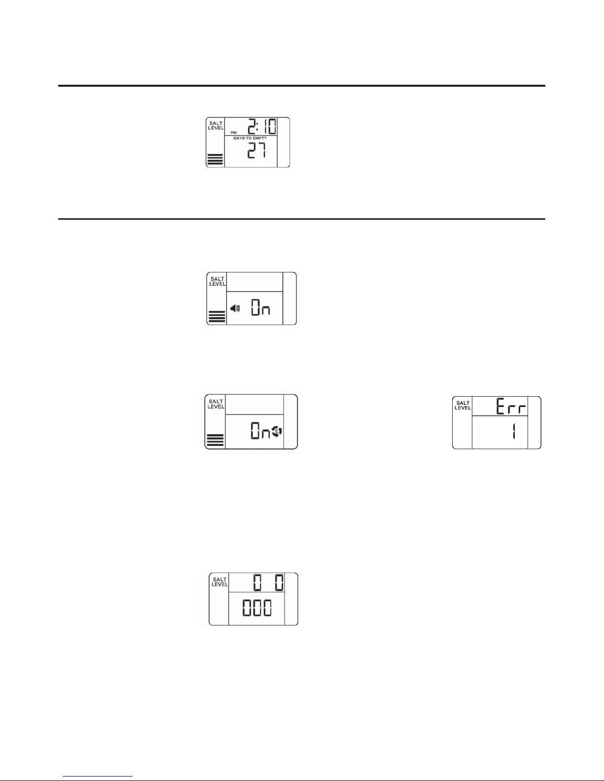
LOW SALT ALARM
The LOW SALT ALARM, when enabled,
will sound the beeper when the DAYS
TO EMPTY value is 15 days or less. To
change this setting, press and hold
the MODE button for 3 seconds. ON
(factory default) or OFF will fl ash in
the display. Press the UP ▲ or DOWN ▼ buttons to toggle this feature
ON or OFF. Press the MODE button to accept, and the display will
move to SALT EFFICIENCY.
SALT EFFICIENCY
When the SALT EFFICIENCY feature
is ON, the unit will operate at a salt
effi ciency of 4000 grains of hardness
removed per pound of salt (59fm3/
kg salt). This mode of operation
is the most effi cient setting for salt
usage, because the system will tend to
recharge more often, with less salt usage. Turning the feature OFF will
tend to lengthen the time between recharge cycles, which will provide
the most effi cient usage of water, but may use more salt. The degree of
difference between these two cycles is highly dependent on the water
usage and hardness at a particular installation.
To change the setting, press the UP ▲ or DOWN ▼ buttons to toggle
the feature ON or OFF. Press the MODE button to accept. The display
will move to SYSTEM/ELECTRONIC DIAGNOSTICS.
SYSTEM/ELECTRONIC DIAGNOSTICS
This display contains system diagnostics
information to assist in troubleshooting
problems with the system.
See page 15 for details. Press the MODE
button to return to the normal run
display.
LOST TIME SIGNAL
If time is lost on the display due to power interruption, the blue
indicator light will fl ash 4 times every second, until the present time of
day is entered.
LOW SALT SIGNAL
When the DAYS TO EMPTY drops to 15, the blue indicator light and
DAYS TO EMPTY in the display will fl ash every second and the alarm will
beep every 30 seconds (from 8:00 AM to 8:00 PM), to notify the user
that the unit is running low on salt. As soon as any button is pressed,
the alarm will stop beeping. The blue indicator light and DAYS TO
EMPTY will continue to fl ash. Once salt is added to the brine tank and
the SALT LEVEL is reset, the DAYS TO EMPTY wil l
be reset.
ERROR SIGNALS
If there is an error code detected, the
blue indicator light will fl ash 4 times
every second, the display will fl ash
Err, and the alarm will beep every 30
seconds (from 8:00 AM to 8:00 PM),
to signal that the softener requires
service. The alarm can be turned off by pressing any button, but the
blue indicator light and display will continue to fl ash.
See page 14 for information to assist in troubleshooting error codes.
Once the problem is corrected, disconnect the transformer from the
wall outlet momentarily, and plug it back in. The normal display will
appear. The motor may run for several minutes, as the unit resets.
If the problem is not corrected, the error code will reappear in 6
minutes.
BLUE INDICATOR LIGHT
Steady blue light indicates that the unit is working correctly. The light
fl ashes
when the unit needs attention from the user.
• Light fl ashes and DAYS TO EMPTY fl ashes—check salt level and add
salt as required.
• Light fl ashes and Err is in the display˜electrical problem
with system˜see page 16.
• Light will also fl ash when power to the unit has been
interrupted. Check the PRESENT TIME setting.
Programming the Control (cont.)
DAYS TO EMPTY
The words DAYS TO EMPTY and a number
are shown in the lower half of the display.
This information is shown in the normal
run display. This is to inform the user of
the number of days before the salt level in
the brine tank reaches Level 0. There will
be salt left in the salt tank, but it may not be suffi cient to fully recharge
the system. Salt should be added at this time to avoid hard water. The
value is updated daily and whenever the SALT LEVEL value is changed.
NOTE: For the fi rst several weeks of operation the DAYS TO EMPTY may
provide erratic operation. For example, the blue indicator light may
fl ash, showing that more salt is required when the actual salt level in
the tank is well above the Level 0. In some cases, the DAYS TO EMPTY
may even increase over a several week period.
It takes a couple of months for the water softener to learn your water
usage pattern. Once it does this, it will accurately determine actual
salt usage pattern. During this fi rst period, check salt level when blue
indicator light fl ashes. If the salt level in the tank is at Level 1 or above,
allow system to run. Be sure to reset your salt level indicator each time
you add salt to the system.
Page 11
10
This system conforms to NSF/ANSI 44 for the specific capacity claims as verified and substantiated by test data.
* Testing was performed using pellet grade sodium chloride as the regenerant salt.
** Efficiency rating is valid only at the lowest stated salt dosage and service flow rate. This softener was efficiency
rated according to NSF/ANSI 44.
*** Extent of iron removal may vary with conditions. The capacity to reduce clear water iron is substantiated by
independent laboratory test data.
Refer to Cleaning Iron Out of the Water Softening System section.
Step-by-step installation instructions.
Sanitizing Procedures
To complete the installation, do the following
sanitizing procedures.
Care is taken at the factory to keep your
water softener clean and sanitary. Materials
used to make the softener will not infect or
contaminate your water supply and will not
cause bacteria to form or grow. However,
during shipping, storage, installing and
operating, bacteria could get into the
softener. For this reason, sanitizing as
follows is suggested when installing.
NOTE: Sanitizing is recommended by the
Water Quality Association for disinfecting.
1. Be sure to complete all installation steps,
including programming the control.
2. Pour about 22.ml (1
1
⁄2 tablespoons) of
common 5.25% unscented household bleach
(Clorox, Linco, Bo Peep, White Sail, Eagle,
etc.) into the brinewell. Refer to illustration
on page 5.
3. IMPORTANT: Press and hold for 3 seconds
the faceplate RECHARGE button to start
an immediate recharge. RECHARGE begins
to flash in the display. The bleach will be
drawn through the water softener and out
the drain. This process takes approximately
2 hours.
4. If, after sanitization, water from the house
faucet tastes salty or has a slight color, this is
a preservative from the resin tank. Turn on
the cold soft water faucets and drain for a
few minutes or until clear.
NOTE: When the above sanitizing regeneration
is over, all remaining bleach is flushed from the
conditioner and your house COLD water supply
is fully soft immediately. However, your water
heater is filled with hard water and as hot water
is used, all remaining bleach is flushed from
the system and it will refill with soft water.
When all the hard water is replaced in the
water heater, hot only and mixed hot and cold
water will be fully soft. If you want totally soft
water immediately, after the above recharge,
drain the water heater until the water runs
cold.
WARNING:If you do drain the
water heater, use extreme care as the hot
water could cause burns. Turn the water
heater off prior to draining.
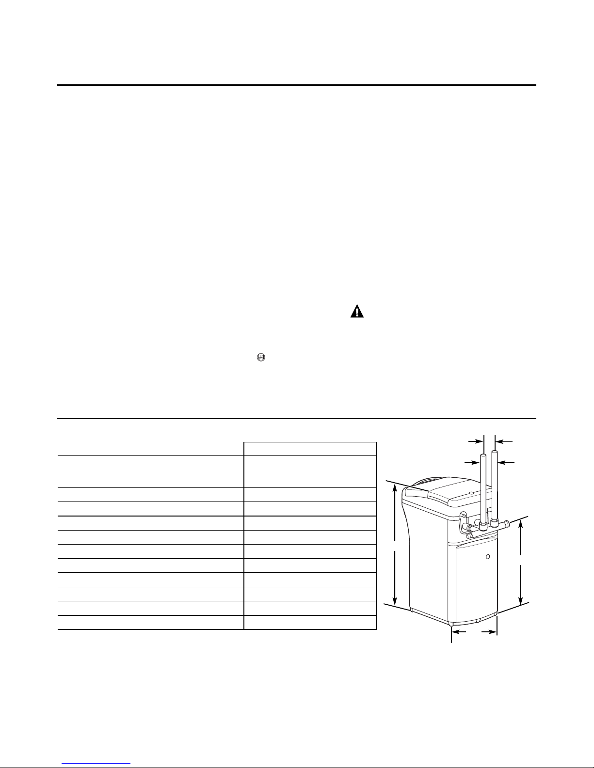
Specifications/Dimensions
GXOF18K
Rated Capacity 5.2 mols with 0.80 kg of salt
8.6 mols with 1.7 kg of salt
12.2 mols with 4.6 kg of salt
Rated Efficiency 6.2 mols/kg @ 0.8 kg salt dose
Amount of High Capacity Resin (kg/liters) 15.1/18
Resin Tank Nominal Size (in., dia. x height) 10 x 21
Service Flow Rate (l/min) 26.5
Water Supply Maximum Hardness (gpg) 95
Water Supply Maximum Clear Water Iron (ppm) 5
Water Pressure Limits (min.–max. bar) 1.4 - 8.6
Pressure Drop at Rated Service Flow (bar) 0.55
Water Temperature Limits (min.–max. °C) 4 - 49
Maximum Flow Rate to Drain (l/min) 8.3
Inlet Outlet
8.6 cm
58.2 cm
36.8 cm
76.2 cm
Page 12

11
About the water softener system. GEAppliances.com
Service
When the water softening system is providing
soft water, it is called “Service.” During service,
hard water flows from the house main water
pipe into the water softening system. Inside the
water softening system resin tank is a bed made
up of thousands of tiny, plastic resin beads. As
hard water passes through the bed, each bead
attracts and holds the hard minerals. This is
called ion-exchanging. It is much like a magnet
attracting and holding metals. Water without
hard minerals (soft water) flows from the water
softening system and to the house pipes.
After a period of time, the resin beads become
coated with hard minerals and they have to be
cleaned. This cleaning is called recharge.
Recharge is started at 2:00 AM (factory setting)
by the water softening system control, and
consists of five stages or cycles. These are
FILL, BRINING, BRINE RINSE, BACKWASH and
FAST RINSE.
For emergency needs, hard water is available
to the home during the recharge cycles.
However, you should avoid using HOT water
because the water heater will fill with the
hard water.
Automatic Hard Water Bypass During Recharge
Fill
Salt dissolved in water is called brine. Brine is
needed to clean the hard minerals from resin
beads. To make the brine, water flows into the
salt storage area during the fill stage.
Brining
During brining, brine travels from the salt
storage area into the resin tank. Brine is the
cleaning agent needed to remove hard minerals
from the resin beads. The hard minerals and
brine are discharged to the drain.
The nozzle and venturi create a suction to
move the brine, maintaining a very slow rate
to get the best resin cleaning with the least salt.
Brine Rinse
After a pre-measured amount of brine is used,
the brine valve closes. Water continues to flow
in the same path as during brining, except for
the discontinued brine flow. Hard minerals and
brine flush from the resin tank to the drain
.
Backwash
During backwash, water travels up through
the resin tank at a fast flow rate, flushing
accumulated iron, dirt and sediments from
the resin bed and to the drain.
Fast Rinse
Backwash is followed by a fast flow of water
down through the resin tank. The fast flow
flushes brine from the bottom of tank, and
packs the resin bed.
After fast rinse, the water softening system
returns to soft water service.
Page 13
12
About the water softener system.
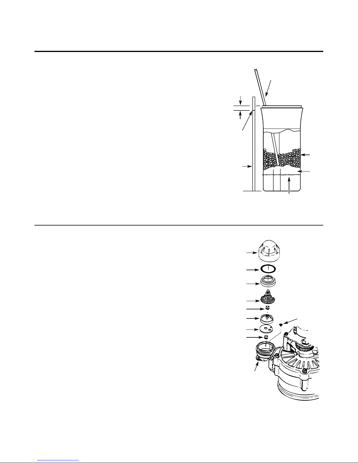
Breaking a Salt Bridge
Sometimes, a hard crust or salt bridge forms in
the salt storage area. It is usually caused by high
humidity or the wrong kind of salt. When the
salt bridges, an empty space forms between the
water and salt. Then salt will not dissolve in the
water to make brine.
If the brine tank is full of salt, it is hard to tell
if you have a salt bridge. Salt is loose on top,
but the bridge is under it. The following is the
best way to check for a salt bridge.
Salt should be loose all the way to the bottom
of the tank. Take a broom handle or like tool,
and carefully push it down into the salt,
working it up and down. If the tool strikes
a hard object (be sure it’s not the bottom or
sides of the tank), it’s most likely a salt bridge.
Carefully break the bridge with the tool.
Do not pound on the walls of the tank.
If the wrong kind of salt made the bridge, take
it out. Then fill the tank with nugget or pellet
salt only. In humid areas, it is best to fill with
less salt, more often to prevent a salt bridge
from forming.
A clean nozzle and venturi is needed for the
water softening system to work properly. This
small unit makes the suction to move brine
from the salt storage area to the resin tank
during recharge. If it becomes plugged with
sand, dirt, etc., the water softening system
will not work and you will get hard water.
To get to the nozzle and venturi, remove
the water softening system top cover. Be sure
the water softening system is in service cycle
(no water pressure at nozzle and venturi).
Then, while holding the nozzle and venturi
housing with one hand, remove the cap. Lift
out the screen support and screen, then the
nozzle and venturi. Wash and rinse the parts in
warm water until clean. If needed, use a small
brush to remove iron or dirt. Also check and
clean the gasket.
NOTE: Some models have a small flow plug
located in the nozzle and venturi, and/or
a small cone shaped screen in the housing.
Be sure to check and clean these parts,
if your model is so equipped.
Carefully replace all parts in the correct order.
Lightly lubricate the o-ring seal with clean
silicone grease or petroleum jelly and place in
position. Install and tighten the cap, by hand only.
Do not overtighten the cap.
Cleaning the Nozzle and Venturi Assembly
Push tool into salt
bridge to break
Pencil
mark
Broom
handle
Salt
Salt
bridge
Water level
2−5 cm
IMPORTANT: Be sure small holes in the gasket are
centered directly over the small holes in the nozzle and
venturi housing.
*Install with numbered side up, concave side down.
Cap
O-ring seal
Screen support
Screen
Screen
Nozzle & Venturi
Nozzle & Venturi
housing
Gasket
*Flow plug
*Flow plug
Page 14

13
GEAppliances.com
During normal operation, the present time of
day and AM or PM and DAYS TO EMPTY show
in the control display area. When the demand
computer determines a recharge is needed,
RECHARGE TONIGHT begins to flash in the
display along with the present time. RECHARGE
TONIGHT flashes until the next recharge start
time, then changes to RECHARGE, which flashes
until the recharge is over.
Normal Operation, Control Displays
Sometimes, a manually started recharge may
be desired or needed. Two examples:
■ You have used more water than usual
(house guests, extra washing, etc.) and
you may run out of soft water before the
next recharge.
■ The system ran out of salt.
Use one of the following features to start
a recharge immediately, or at the next preset
recharge start time.
RECHARGE TONIGHT
Touch (do not hold) the RECHARGE button.
RECHARGE TONIGHT flashes in the control
display area. A recharge will occur at the next
preset recharge start time. If you decide to
cancel this recharge, touch the same button
once more.
RECHARGE
Press and hold the RECHARGE button until
RECHARGE starts to flash in the control display
area. The water softening system begins an
immediate recharge and, when over in about
two hours, you will have a new supply of soft
water. Once started, you cannot cancel this
recharge.
Feature: Optional Recharge Controls
Feature: Memory
If electrical power to the water softening system
is interrupted, the control display is blank, and
the blue indicator light is off, but the control
keeps correct time for about 6 hours. When
power is restored, you have to reset the present
time only if the display and blue indicator light
are flashing. All other settings are maintained
and never require resetting unless a change
is desired.
If the time is flashing after a long power outage,
the water softening system continues to work
as it should to provide you with soft water.
However, recharge may occur at the wrong time
of day until you reset the control to the correct
time of day.
The control computer has a self-diagnostic
function for the electrical system (except
input power and water meter). The computer
monitors the electronic components and
circuits for correct operation. If a malfunction
occurs, an error code appears in the
control display.
The chart on Error Codes shows the error codes
that could appear and possible reasons for each
code. See Manually Initiated Electronic Diagnostics
to further isolate the defect.
Feature/Service: Automatic Electronic Diagnostics
Page 15
14
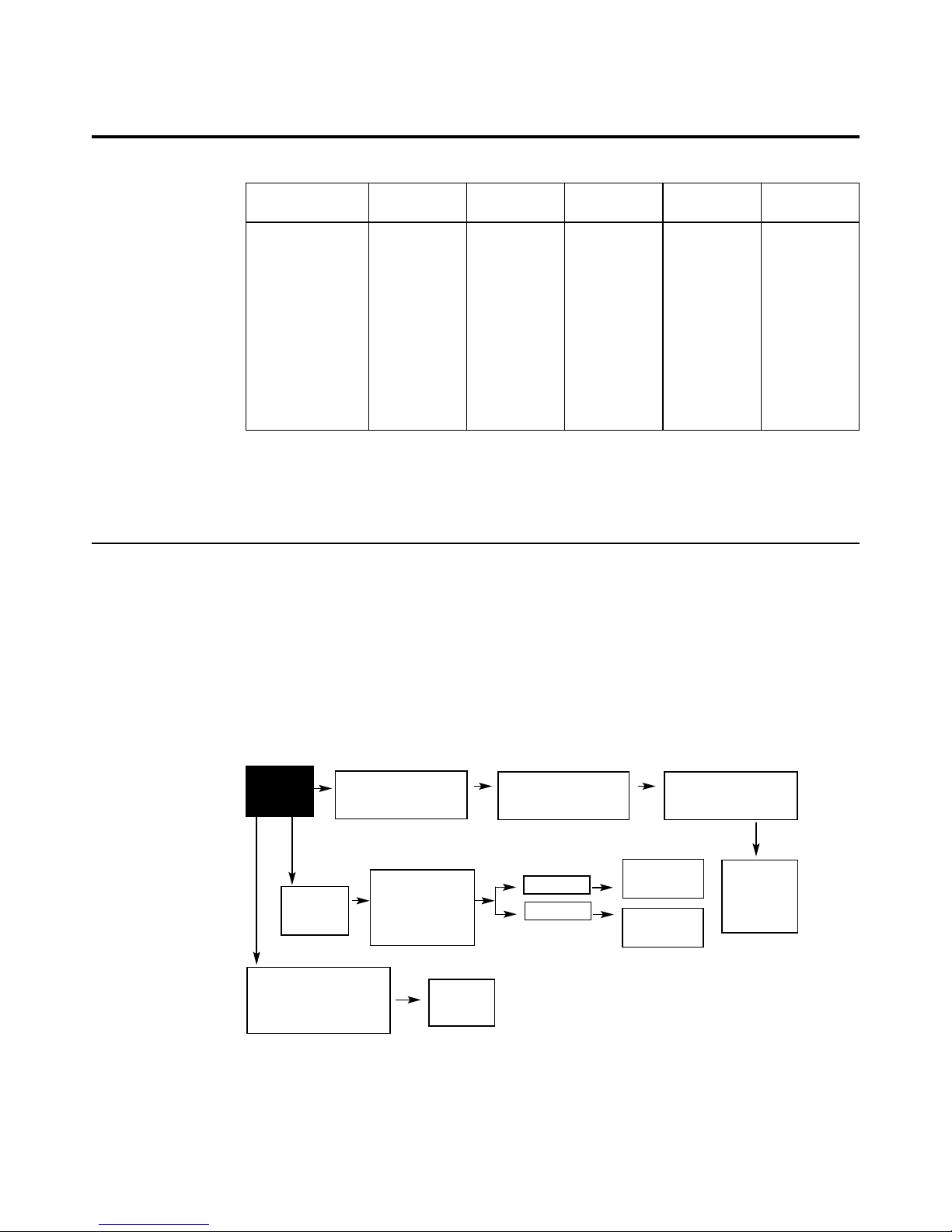
To remove an error code: 1. Unplug transformer.
2. Correct defect.
3. Plug transformer in.
4. Wait for at least 6 minutes. The error code will return if the reason for
the error code was not corrected.
NO SOFT
WATER
CONTROL SHOWS
WRONG TIME AND DAY,
AND/OR IS FLASHING.
CONTROL
DISPLAY
BLANK.
CONTROL DISPLAY SHOWS
CORRECT TIME AND DAY
AND IS STEADY.
Check electrical
power to control
(outlet, transformer,
power cable, all
connections).
Do manual
diagnostics.
NOPOWER
POWER OK
REPAIR AS
NEEDED
CONTROL
DEFECTIVE
Do manual
diagnostics to
verify proper
function.
Electrical power was off.
Reset the correct time of
day.
Investigate reason for
power loss.
About the water softener system.
Service: Electronic Demand Time Features and Service
If you are not getting soft water, and an error
code is not displayed, use the procedures below
to find the problem. First make the following
visual checks.
VISUAL CHECKS:
1. Is there electrical power to the outlet the
water softening system transformer is
plugged into?
2. Is there sufficient salt in the storage tank?
3. Is the softener bypass valve directing water
for soft water service?
4. Is the valve drain hose open to the drain,
not more than 2m above the softener, and
unobstructed?
If you do not find a problem with the visual checks,
continue below.
Service: Timer/Softener, Service Checkout Procedure
ERROR CODE
DISPLAYED ERR 01 ERR 02 ERR 03 ERR 04 ERR 05
POSSIBLE DEFECT • Motor • Position • Motor • Position • Control
inoperative switch inoperative switch or
or wiring wiring
harness harness
• Wiring • Control • Control • Control
harness or
connection
to switch
• Position
switch
• Control
Page 16
15
GEAppliances.com
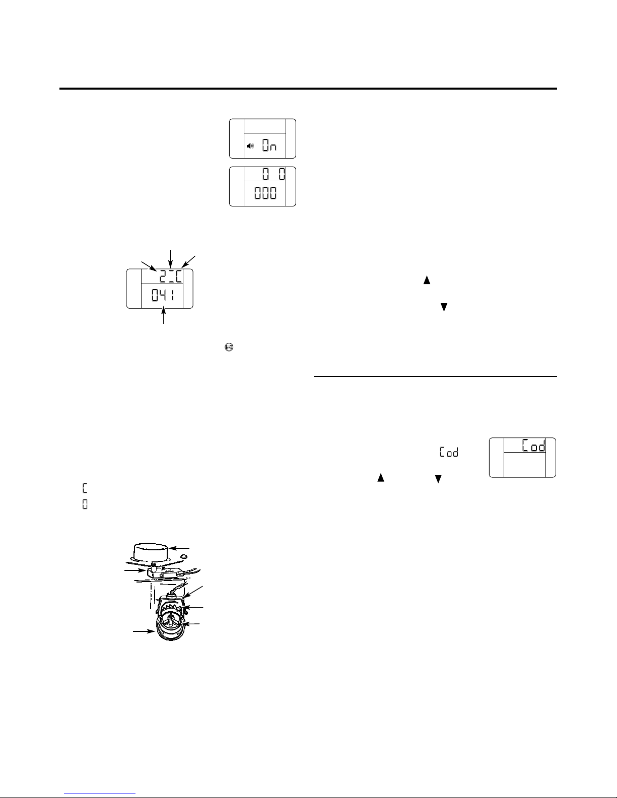
1. To enter diagnostics, press and hold
the MODE button for 3 seconds until
the Low Salt Alarm screen shows.
2. Press the MODE button 2 times to
advance through Low Salt Alarm
and Salt Efficiency options. See
Programming the Control for details
on these two options.
3. OPERATION OF DIAGNOSTICS
• Valve Position – Press the RECHARGE button to
initiate a recharge cycle. Press again to manually index
valve to next position. See Service: Manually Advance
Recharge Check for details.
0 – Service
1 – Fill
2 – Brine
3 – Backwash
4 – Fast Rinse
• Motor Operation – Two dashes will circulate around
when motor should be running.
• Position Switch Operation –
– Closed – valve rotating to next position
– Open – valve in position, service, fill, brine, etc.
• Water Meter – Indicates whether water is flowing
through valve.
– 000 indicates no water is flowing through the valve
– Open nearby soft water faucet
– 000 to 199(continual) shows water is flowing.
Display repeats for each gallon of water passing through the
meter. Control will beep at every gallon. (1 gallon= 3.78 litres)
– If there is no reading in the display, with faucet
open, check the sensor. Pull the sensor from the
valve outlet port, and pass a small magnet in front
of the sensor. Counter should index in the display.
If counter does not index, check to make sure
harness is connected to board properly. If there is
a reading in the display, there may be a problem
associated with the turbine. Turn off water supply,
close the by-pass valve, and disconnect by-pass valve
from valve body. Check turbine for binding or
restriction due to debris. If this does not correct
the problem, the Timer, Sensor, or Turbine may
require replacement.
4. Historical data about the softener is available.
• Press and hold the UP button to display the number
of days this control has had electrical power applied.
• Press and hold the DOWN button to display the
number of recharges initiated by this control since the
model code number was entered.
5. Press the MODE button to return to normal operation
and display.
Service: Set Model (F) Code
1. To change or check model code, first press and hold the
MODE button for 3 seconds until the Low Salt Alarm
screen shows.
2. Press and hold the MODE button again
for 3 seconds. A display with at
the top will appear.
3. Press the UP or DOWN buttons
to select the correct model code.
F18 = GXOF18K
4. Press the MODE button one time to return to normal
operation and display. If the model code was changed:
• the display will go blank momentarily, then display the
model code entered.
• the display will then return to the set present time
display, and the blue indicator light will flash. The
control will have to be reprogrammed. See Programming
the Control.
NOTE: If the control is left in any of the above diagnostic
displays, or a flashing display when setting time, hardness,
etc., it will revert back to the normal display in 4 minutes.
Service: Manually Initiated Electronics Diagnostics
SALT
LEVEL
SALT
LEVEL
SALT
LEVEL
Water meter
Valve
position
Position
switch
Motor
Motor
Turbine
Turbine support
and shaft
Sensor
housing
Position
switch
Valve
outlet
SALT
LEVEL
H45
Page 17
16
About the water softener system.
NOTE: The control display must show a steady
time (not flashing).
1. Press the RECHARGE button and hold in
for three seconds. RECHARGE begins to flash
as the water softening system enters the fill
cycle of recharge. Remove the brinewell
cover and, using a flashlight, observe fill
water entering the brine tank. If water does
not enter the tank, look for an obstructed
nozzle, venturi, fill flow plug or brine tubing.
See Care and Cleaning of the Water Softener
System section.
2. After observing fill, press the RECHARGE
button to move the water softening system
into brining. A slow flow of water to the drain
will begin. Verify brine draw from the brine
tank by shining a flashlight into the brinewell
and observing a noticeable drop in the liquid
level over an extended period of time.
NOTE: Be sure a salt bridge is not preventing
water from contacting salt. See Care and
cleaning of the water softening system section.
If the water softening system does not draw brine,
check:
■ nozzle and/or venturi dirty or defective.
■ defective nozzle and venturi seal.
■ nozzle and venturi not seated properly
on gasket.
■ other inner valve defect (rotor seal, rotor
and disc, wave washer, etc.).
■ restricted drain (check drain fitting and
hose).
NOTE: If water system pressure is low, an
elevated drain hose may cause back pressure,
stopping brine draw.
3. Again, press the RECHARGE button to move
the water softening system into backwash.
Look for a fast flow of water from the drain
hose. A slow flow indicates a plugged top
distributor, backwash flow plug or drain hose.
4. Press the RECHARGE button to move the
water softening system into fast rinse. Again
look for a fast drain flow. Allow the water
softening system to rinse for a few minutes
to flush out any brine that may remain in
the resin tank from the brining cycle test.
5. To return the water softening system to
service, press the RECHARGE button.
Service: Manually Advance Recharge Check
Page 18
17
Care and cleaning of the water softening system. GEAppliances.com
Brine (salt dissolved in water) is needed for
each and every recharge. The water for making
brine is metered into the salt storage area by
the water softening system valve and control.
However, you must keep the tank supplied
with salt.
When to refill with salt: If the blue indicator
light and DAYS TO EMPTY are flashing, there is
less than 15 days supply of salt. Refill with salt.
In humid areas it is best to refill with less salt
and more often, to avoid the forming of a salt
bridge, see page 12. After adding salt,
remember to reset the SALT LEVEL in the
control, see page 8. Never allow the salt level
to drop below zero on the yellow indicator
before you refill it. Without enough salt, you
will soon have hard water.
Use clean water softening salts only, at least
99.5% pure. NUGGET, PELLET or coarse
SOLAR salts are recommended. Do not use rock,
block, granulated or ice cream making salts.
They contain dirt and sediments, or mush and
cake, and will create maintenance problems.
CAUTION: Water softening salt with
iron removing additives: Some salts may have
an additive to help the water softening
system handle iron in the water supply.
Although this additive may help to keep the
water softening system resin clean, it may
also release corrosive fumes that weaken
and shorten the life of some water softening
system parts.
Checking the Salt Storage Level and Refilling
Your water softening system takes hardness
minerals (calcium and magnesium) out of
the water. Also, it can control some (see the
Specification Guidelines section) “clear water”
iron. With clear water iron, water from a faucet
is clear when first put into a glass. After 15 to
30 minutes, the water begins to cloud or turn
rust colored. A water softening system will not
remove any iron that makes the water cloudy
or rusty as it comes from the faucet (called red
water iron). To take red water iron out of water,
or over the maximum of clear water iron,
an iron filter or other equipment is needed.
If your water supply has clear water iron,
periodic resin bed cleaning is needed.
Clean the bed at least every six months, or more
often if iron appears in the soft water between
cleanings.
IMPORTANT: It is important to mix the resin bed
cleaner with water (following the manufacturer’s
instructions), pour it into the brinewell tube
(see page 5) and recharge the softener
immediately. Do not pour the resin bed cleaner
in with the salt, as it will not be as effective in
cleaning the resin, and can cause damage to
the softener if it is left in the brine tank for an
extended period due to the corrosive gases that
are formed.
Cleaning Iron Out of the Water Softening System
Page 19
18
Troubleshooting Tips
Save time and money! Review the chart on this
page first and you may not need to call for service.
Problem Possible Causes What To Do
No soft water Faucet or fixture where sample was •
To conserve salt, the installer
may have isolated some fixtures
taken not plumbed to soft water.
(outside faucets, toilets, etc.)
from soft water. From the outlet
NOTE:
Be sure sample is from a faucet of the water softening system, trace the water flow path,
that does not mix soft and hard water. in house plumbing. If soft water is not directed to a faucet
For example, a single lever kitchen faucet, or
fixture where wanted, consult a plumber.
if the cold side is plumbed to hard water.
No salt in the brine tank or • Check for a salt bridge or, if the
tank is empty, refill with
salt bridged recommended salt. Press (for 3 seconds) the RECHARGE
button to start an immediate recharge and restore
soft water supply.
Transformer unplugged at wall outlet or
• Check for a loss of electrical power to the water softening
power cable to softener not connected. system, due to any of these conditions and correct as needed.
Fuse blown or circuit breaker popped With the power supply restored, observe the faceplate time
on circuit to electrical outlet. display and read Programming the Control section.
Electrical outlet on a circuit that can
NOTE: The electrical outlet for the softener should be continuously
be switched off
live
so it cannot be accidentally switched off.
Manual bypass valve in bypass position • Be sure the bypass valve stem
is positioned properly, with the
knob in the OUT position. Observe i
nstructions on the decal
at the end of the stem. Check the position of bleed screw.
Valve drain hose pinched, plugged, •
Any restriction in this drain hose
may prevent proper
elevated too high or otherwise
operation of the
nozzle and venturi and reduce or prevent
restricted brine draw during recharge.
Nozzle and venturi dirty, incorrectly • Refer to Cleaning the Nozzle and Venturi Assembly
instructions.
assembled or damaged
With water pressure to the
water softening system off, take
the nozzle assembly apart. Inspect, clean and replace as
needed. Any foreign particle(s), scratches, nicks, etc., in the
passages can
prevent operation. Be sure holes in the gasket are
centered over holes in the housing.
NO SOFT WATER – Most Common Problems:
Check the following before calling for service:
•
Not enough salt—should be at least 1/3 full.
•
Bypass valve in “Bypass” position—knob should be in the “OUT” (service) position.
•
Hardness setting too low. Check hardness setting and adjust. Verify hardness of
supply water—from local water company, water test or call the GE Answer Center.
•
Salt Bridge—salt solidifies above water level so that brine water is not in contact
with salt. See the Breaking a Salt Bridge section.
Before you call for service…
Page 20

19
Problem Possible Causes What To Do
Water hard sometimes Using hot water while the water • Avoid using hot water during water softening system
softening system is regenerating recharge because the water heater will refill with hard water.
See Automatic Hard Water Bypass During Recharge section,
page 11.
Control HARDNESS number setting • Press the MODE button until arrow points to HARDNESS.
too low Be sure the number shown is the same as the actual grains
per gallon hardness of your water supply. See the
Programming the Control section if a change in the setting
is needed.
Grains of hardness in your water •
Water hardness can change
over time, especially in well water.
supply have increased To check, have the water tested by a water analysis laboratory
or call your local water department. Adjust the HARDNESS
number setting as needed.
Water feels slippery Absence of hardness minerals • This is normal. Hardness in water gives it the abrasive feel
after installation of you may have been accustomed to. The slippery feel is the
water softening system clean feel of soft water.
Water softening system Water softening system is a • Does not use much salt to regenerate—very efficient.
not using any salt “demand” unit
Possible salt bridge • See the About the Water Softener System section, page 12.
Possible plugged nozzle and venturi • See the About the Water Softener System section, page 12.
Water is blue color Acidic water in copper plumbing • Have the water tested at once.
after water softening
system was installed
Water softening system Meter turbine stuck • See the Service: Manually Initiated Electronics Diagnostics
not regenerating section for troubleshooting procedures, page 15.
• Call for service.
Sensor wire not plugged into • See the Service: Manually Initiated Electronics Diagnostics
the control section for troubleshooting procedures, page 15.
• Call for service.
No power to unit • Check the circuit breaker or fuses.
Mechanical defect • Call for service.
Cloudiness on glassware Combination of soft water and • This is called etchingand is permanent. To prevent this
(automatic dishwashers) too much detergent from happening, use less detergent if you have soft water.
Wash glassware in the shortest cycle that will get them clean.
Excessive/high level Valve drain hose pinched, • Any restriction in this drain hose may prevent proper
of water in brine tank plugged, elevated too high operation of the nozzle and venturi and reduce or prevent
or otherwise restricted brine draw during recharge.
Nozzle and venturi dirty, incorrectly • See the Cleaning the Nozzle and Venturi Assembly section,
assembled or damaged page 12. With water pressure to the water softening system
off, take the nozzle assembly apart. Inspect, clean and
replace as needed. Any foreign particle(s), scratches, nicks,
etc., in the passages can prevent operation. Be sure holes
in the gasket are centered over holes in the housing.
GEAppliances.com
Page 21

20
Problem Possible Causes What To Do
Salty tasting or Unit not sanitized • Complete the Sanitization Procedureson page 10.
brown/yellow colored
• At completion of recharge cycle(approx. 2 hrs), run water
water after installation
from faucets to purge the salty water.
Low water pressure • Check pressure; should be minimum1.4 Bar.
Restricted drain hose • Clean and reconnect hose.
• Check for kinks in drain line.
Brown/yellow Unit was idle for a period of time • Complete the Sanitization Procedures on page 10.
colored water
Resin beads showing Cracked distributor • Call for service.
up in drinking water
and sink
Sounds you might hear Running water from the unit •This is normal.
into a drain during recharge
Water has air bubbles Air in system after installation •Will go away after it runs for a while.
and is cloudy
Error Code on control Wiring may have worked loose • See page 14 for details.
in the control
• Unplug transformer.
• Remove control cover, release clips on side.
• Check for loose/incorrect wiring connections to electronic
board or switch. Reconnect as required.
• Reassemble control cover.
• Plug in Transformer.
• Wait six minutes for Error Code to reappear.
• If Error Code reappears, call for service.
Troubleshooting Tips
Before you call for service…
Blue light flashing
When power applied Control needs to be programmed • See the Programming the Controlsection, page 8.
to the system (a power outage may have occurred)
If “DAYS TO EMPTY” Low salt level, less than 15 days • Fill with salt.
is flashing
•Reset salt level.
If “Err” in display Electrical problem with system • See page 14 for details.
•See procedure above, Error code on control.
Page 22

Sistema Suavizante
De Agua
Información de seguridad . . . . . . 22
Instrucciones para la instalación 23–32
Instrucciones paso por paso . . . . . . . . . .26-32
Instrucciones para la operación
Cómo romper un puente de sal . . . . . . . . . 34
Cómo limpiar la ensambladura
de la boquilla y el Venturi . . . . . . . . . . . . .35
Funciones . . . . . . . . . . . . . . . . . . . . . . . . .36
Servicio . . . . . . . . . . . . . . . . . . . . . .33,37,38
Sistema de descalcificación de agua . . . . . . 33-38
Cuidado y limpieza . . . . . . . . . . 40
Consejos para la solución de averías .41-43
Soporte al cliente
Lista de parte. . . . . . . . . . . . . . . . . . . . . 87
Lista de partes/cat logo
La Página 87
GEAppliances.com
#30500 General GXOF18K EURO Version 10-01
Escriba aquíel modelo y los números
de la serie:
Modelo No. ____________________
Serie No. ______________________
Para encontrar estos n múeros,
levante la cubierta y mire en el
borde, debajo del panel del control.
Modelos GXOF18K
Manual del Propietario e
Instrucciones de Instalación
Sistema Suavizante
de Agua
Page 23
INFORMACIÓN IMPORTANTE DE SEGURIDAD.
LEA TODAS LAS INSTRUCCIONES ANTES DEL USO.
PRECAUCIONES DE SEGURIDAD
■ Revise y cumpla con todos los códigos estatales y
locales. Observe las pautas aquí presentadas.
■ Tenga cuidado al manipular el sistema de
descalcificación de agua. No lo voltee, deje caer,
arrastre o coloque en protuberancias extremas.
■ Los sistemas de descalcificación de agua que utilicen
cloruro de sodio (sal) para la recarga agregan sodio
al agua. Las personas que siguen dietas con
restricciones de sodio deben considerar el sodio
adicional como parte de su consumo general. El cloruro
de potasio puede servir como una alternativa para el
cloruro de sodio de su descalcificador.
■
El sistema de descalcificación de agua funciona
solamente con 24 voltios-50 Hz.
Cerciórese de usar
exclusivamente el transformador incluido.
■ El transformador se debe conectar únicamente
a un tomacorriente interior con conexión a tierra
de 220 - 240 voltios.
■ Utilice únicamente sales para descalcificación
del agua, al menos con 99.5% de pureza. Se
recomiendan las sales en PEPITAS, BOLITAS
o SAL GRUESA SOLAR. No utilice sales en roca,
bloque, granuladas o sales para la elaboración
de helados. Éstas pueden contener suciedad y
sedimentos, o pasta y masa y podrían crear
problemas de mantenimiento.
■ Mantenga la tapa del orificio de la sal en su lugar en
el descalcificador a menos que esté realizando
mantenimiento o reponiendo la sal.
ADVERTENCIA: No use con agua que
sea microbiológicamente insegura o de calidad
desconocida sin llevar a cabo la desinfección
adecuada antes o después del sistema.
LEA Y SIGA ESTA INFORMACIÓN DE SEGURIDAD CUIDADOSAMENTE.
GUARDE ESTAS INSTRUCCIONES
INSTALACIÓN CORRECTA
■ Instale o almacene donde no quede expuesto a
temperaturas por debajo del punto de congelación
ni esté expuesto a ningún tipo de inclemencias
atmosféricas. Si el agua llega a congelarse dentro
del sistema, éste podría romperse. No intente dar
tratamiento al agua si se encuentra a una
temperatura por encima de 37 ºC.
■ No instale expuesto a los rayos directos del sol.
Exposición al sol a calor excisivos podrían causar
distorsión u otros daños a las partes no metálicas.
■ Conecte a tierra de manera apropiada según los
códigos y ordenanzas aplicables.
■ Use solamente fundente y soldadura sin plomo para
todas las conexiones de condensación soldadas,
según los códigos estatales y federales aplicables.
■
El sistema de descalcificación de agua requiere un
flujo de agua mínimo de 11 litros por minuto en
la entrada. La presión de entrada máxima permitida
es de 8.6 bar. Si la presión durante el día es por
encima de 5.5 bar, la presión nocturna podría exceder
el máximo. Use una válvula reductora de presión
para reducir el flujo si es necesario.
■
Las resinas de descalcificación podrían degradarse
ante la presencia de cloro por encima de 1 ppm.
Si usted tiene una cantidad de cloro mayor a ésta,
quizás experimente una vida menor de la resina.
En estas condiciones, es posible que quiera
considerar la compra de un sistema de filtración
del punto de admisión para casas GE con un filtro
reductor de cloro.
ADVERTENCIA:Deseche todas las
partes y los materiales de embalaje no utilizados
después de la instalación. Partes pequeñas
restantes después de la instalación podrían
representar un peligro de asfixia.
Este sistema de descalcificación de agua debe instalarse correctamente y colocarse de acuerdo a las
instrucciones de instalación antes de su uso.
22
Por su seguridad, se debe seguir la información en este manual con el fin de reducir el riesgo de una
descarga eléctrica, daños a la propiedad o daños personales.
ADVERTENCIA
Page 24
23
PRECAUCIÓN: Se necesita cierta habilidad de plomería para la instalación.
Si usted no está seguro acerca de la instalación de alguna de las partes de este producto,
consulte a un plomero profesional.
Instrucciones de instalación.
Desempacado e inspección
Cerciórese de inspeccionar completamente el
descalcificador en busca de daños durante el
envío o partes que puedan haberse perdido.
También revise en busca de daños en la caja
de envío. Póngase en contacto con la compañía
de transporte para cualquier reclamo por daño
o pérdida. El fabricante no es responsable por
daños sufridos durante el tránsito.
Las partes pequeñas necesarias para instalar el
descalcificador se encuentran en una pieza de
cartón termoconformada. Para evitar la pérdida
de las partes pequeñas, manténgalas en el
paquete termoconformado hasta que usted
esté listo para usarlas. Cerciórese deno
descartar componentes que podrían estar
escondidos en el embalage.
■ Antes de comenzar la instalación, lea estas
Instrucciones de instalación completamente.
Luego, obtenga todos los materiales y
herramientas que necesita para llevar a cabo
la instalación. No instalar correctamente el
descalcificador invalida la garantía.
■ Revise los códigos locales. La instalación
debe cumplir tales requisitos.
■ Consulte a su plomero certificado, si tiene
alguna pregunta sobre el código de Plomería.
■ Use solamente fundente y soldadura sin
plomo para todas las conexiones de
condensación soldadas, según los códigos
estatales y federales aplicables.
■ Conecte el descalcificador en la tubería
de suministro principal antes del calentador
de agua. NO HAGA PASAR AGUA CALIENTE
A TRAVÉS DEL DESCALCIFICADOR. La
temperatura del agua que pase a través
del descalcificador debe ser menor de
49 ºC.
■ Tenga cuidado cuando manipule el
descalcificador. No lo coloque boca arriba,
ni lo deje caer, ni lo arrastre, ni lo apoye
en protuberancias.
■ La presión de entrada máxima permitida
es de 8.6 bar. Si la presión durante el día es
por encima de 5.5 bar, la presión nocturna
podría exceder el máximo. Use una válvula
reductora de presión para reducir el flujo si
es necesario. (Agregar una válvula reductora
de presión podría reducir el flujo.)
■ El sistema de descalcificación funciona
solamente con 24 voltios-50 Hz. Cerciórese
de usar exclusivamente el transformador
incluido. Cerciórese de que el tomacorriente
eléctrico y el transformador están en el
interior de un recinto para protegerlos
de la humedad.
■ Consulte la sección Dónde instalar el
descalcificador para más detalles.
ADVERTENCIA:No use con
agua que sea microbiológicamente
insegura o de calidad desconocida sin
llevar a cabo la desinfección adecuada
antes o después del sistema. El agua debe
probarse periódicamente para verificar
que el sistema se encuentra funcionando
satisfactoriamente.
■ Partes pequeñas restantes después de la
instalación podrían representar un peligro
de asfixia. Deseche con toda seguridad.
Recomendaciones importantes para la instalación
Lea el manual completo. Ignorar las directrices y reglas podría causar lesiones personales o
daños a la propiedad.
Page 25
24
Instrucciones de instalación.
Dónde instalar el Descalcificador
■ Coloque el descalcificador lo más cercano
posible a un sumidero, o a otro punto de
drenaje o columna de suministro.
■ Se recomienda que los grifos externos se
dejen con agua dura para así ahorrar agua
descalcificada y sal.
■
No instale el descalcificador en un lugar
donde se pueda congelar. Los daños debido al
congelamiento no están cubiertos por la garantía.
■ No instale el descalcificador donde pueda
bloquear el acceso al calentador de agua o el
acceso a la válvula de cierre principal del agua.
■ Coloque el descalcificador en un lugar donde
sea menos probable que ocurra daño causado
por el agua si es que eventualmente ocurriese
alguna fuga. El fabricante no reparará ni pagará
por daños ocasionados por agua.
■ Un tomacorriente de 220-240 voltios es necesario
para conectar el transformador que viene
incluido. El descalcificador tiene un cable
eléctrico de 2 métros. Si el tomacorriente está
colocado demasiado lejos (hasta 30 métros),
use un cable de 0.8 mm2 para conectarlo.
Cerciórese de que el tomacorriente eléctrico y el
transformador estén en el interior de un recinto
para protegerlos de la humedad. Cerciórese de
que el tomacorriente esté desconectado para
prevenir un corte eléctrico accidental.
■ Si se dispone a llevar a cabo la instalación en
el exterior, debe tomar las medidas necesarias
para asegurarse de que el descalcificador, la
instalación de plomería, el cableado, etc.
están también protegidos de los elementos
(rayos del sol, lluvia, viento, calor, frío), de la
contaminación, vandalismo, etc. tal y como lo
estarían si fueran instalados internamente. La
instalación en el exterior no es recomendada, y
anula la garantía.
■ Mantenga el descalcificador alejado de los rayos
directos del sol. El calor del sol podría causar
distorsión u otros daños a las partes no
metálicas y podría hacer daño a las partes
electrónicas.
■ Los accesorios de entrada y salida incluidos
con el descalcificador son de 1".
Debe mantener un tamaño igual o mayor de
tubos que los tubos del suministro del agua,
hacia la entrada y salida del descalcificador.
■ Use la válvula de bypass incluida para instalar el
descalcificador. La válvula de bypass le permite
desconectar el suministro de agua hacia el
descalcificador para efectuar servicio, pero aún
mantiene el agua llegando a las tuberías de la
casa.
■ Use accesorios y tuberías de cobre, latón o
galvanizados. Algunos códigos podrían permitir
el uso de tuberías plásticas CPVC.
■ Si una manguera adicional es necesaria para el
drenaje de la válvula y el tanque de sal, usted la
puede.
■ Si necesita una válvula rígida de drenaje para
cumplir con los códigos de plomería, podrá
comprar las partes necesarias para conectar
un drenaje de tubería de cobre o plástico de
1/2″ (1.27 cm).
■ Sal del descalcificador en una pepita limpia o
bolita de agua es necesaria para llenar el tanque
de agua salmuera, consulte las Instrucciones de
Instalación Paso por Paso en el Paso 8.
Herramientas y materiales necesarios para la instalación
Lo primero que debe decidir es cómo instalar las
tuberías que entran y salen del descalcificador.
Fíjese en la tubería de agua en el punto donde
conectará el descalcificador. ¿La tubería está
soldada con cobre, pegada con plástico, o roscada
galvanizada? ¿Cuál es el tamaño de la tubería?
ADVERTENCIA: Use solamente
fundente y soldadura sin plomo para todas las
conexiones de condensación soldadas, según
los códigos estatales y federales aplicables.
Consulte la Ilustración de instalación normal, Fig. 1.
Úsela como una guía para planificar su instalación
particular. Cerciórese de dirigir el suministro de
agua dura entrante al acoplamiento de admisión
de la válvula del descalcificador. La válvula está
marcada IN (ENTRADA) y OUT (SALIDA). Consulte
la ilustración en la página 25 como ayuda para la
preparación.
Planifique la instalación del Descalcificador
Page 26
25
GEAppliances.com
Illustracióon de instalacion normal
Agua descalcificada
Agua dura hacia los
grifos externos
TUBERIA DE AGUA PRINCIPAL
Agua dura
NOTA: Ver la seccion Conexiones de la manguera de drenaje.
Transformador de 24V
Tomacorriente de 220 -240 voltios
Valvula de bypass
Agua dura hacia
los grifos externos
Valvula de entrada
Valvula de salida
Sistema de derivacion de 3 valvulas
Para el servicio de agua descalcificada:
• Abra las valvulas de entrada
y saldia
• Cierre la valvula de bypass
Para circunvalar el agua dura:
• Cierre las valvulas de entrada
y salida
• Abra la valvula de bypass
LA SAL
VA ACQUI
Deposito de la salmuera
ENTRADA
Arandela (2) (no incluida)
Tubo de cobre, 3/4″ (2) (no incluido)
Tuerca de instalacion (2) (no incluida)
Valvula de bypass
• Tire hacia afuera para servicio de agua descalcificada
• Empuje para bypass
NOTA: Las acesorios proporcionados son para
plomeria de cobre de 3/4″. Si usted tiene plomeria de 1", no use los tubos de cobre y las tuercas incluidas. Compre
adaptadores hembras NPT de 1" y conectelos directamente a las rocas macho NPT de 1" de la valvula de bypasss.
Tuerca (2) (no incluida)
Tubo de cobre de 3/4″ (2) (no incluido)
Arandela (2) (no incluida)
Adaptador de instalacion (2) (ver ariba)
NOTA: Los acesorios proporcionados son para plomeria de cobre de 3/4". Si usted tiene plomeria de 1", no
use los tubos de cobre y las tuercas incluidas. Compre adaptadores hembras NPT de 1" y conectelos directamente
a las roscas macho NPT de 1" del adaptador.
ENTRADA
Union (2) (no incluida)
Illustracion de la instalacion opcional de una derivacion de 3 valvulas
Fig. 1
VIA DE ENLACE
Si el flujo de suministro fluye desde la izquierda.
Incuya una derivacion sencilla o de 3 valvulas.
Agua dura
De la salida del
descalcificador
Agua descalcificada
Hacia la entrada
del descalcificador
Fig. 2
VIA DE ENLACE
Si el flujo de suministro fluye desde la izquierda.
Incluya una derviacion sencilla o de 3 valvulas.
Agua dura
De la salida del
descalcificador
Agua descalcificada
Hacia la entrada del
descalcificador
TUBERIA DE AGUA PRINCIPAL
Agua dura
Agua descalcificada
Tomacorriente de 220 - 240 voltios
Transformador de 24V
Deposito de la salmuera
LA SAL
VA AQUI
Retenedora
Drain
(not shown)
Tapa del orificio
de la sal
Tapa del orificao de
la sal
Page 27
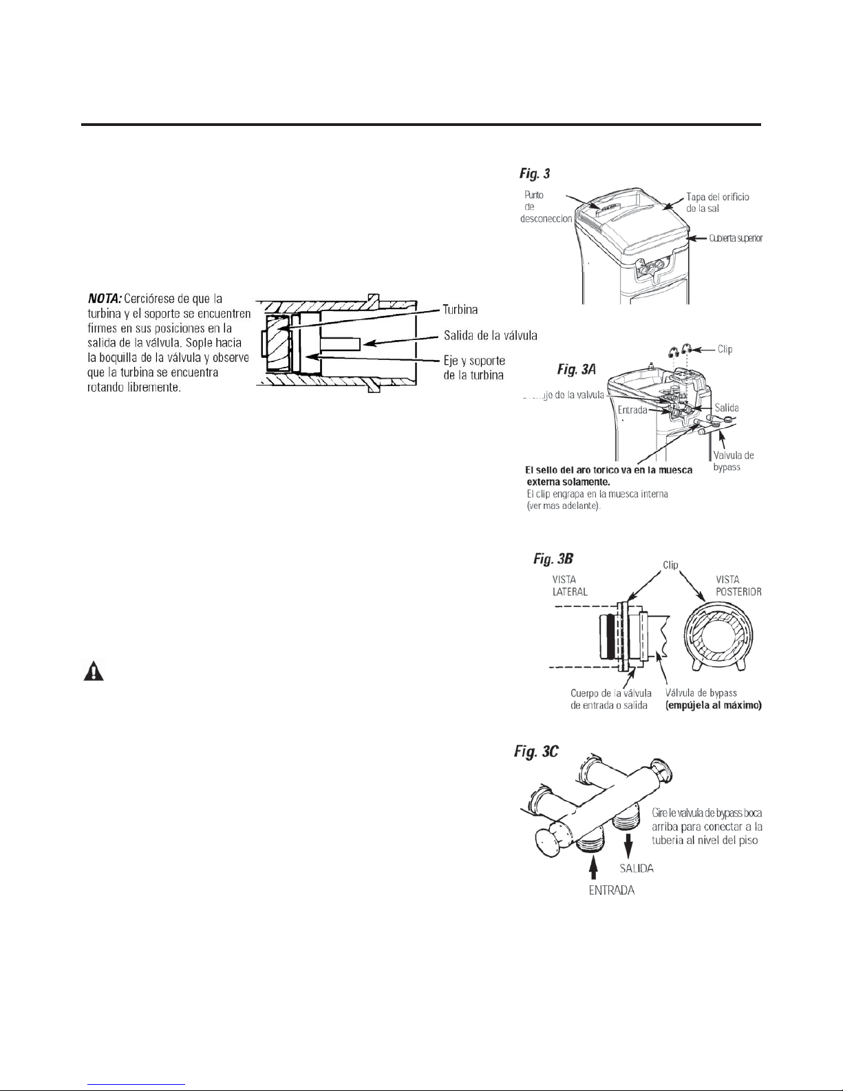
26
Instrucciones de instalación paso por paso.
■ Suspenda el suministro de gas o de energía eléctrica que alimenta el
calentador de agua, en la posibilidad de que el calentador pueda drenarse
mientras usted drena las tuberías.
■ Desconecte el suministro de agua hacia los tubos que han de ser cortados y
drene las tuberías de agua de la casa.
■ Abra los grifos de agua caliente y los de agua fría.
NOTA : Para una más fácil instalación, remueva la cubierta superior. (Fig 3)
1. INSTALE LA VÁLVULA DE BYPASS (varios tipos de bypass possible)
• Remueva el tapón plástico de embalaje y el cable de la salida de la válvula.
• Empuje la válvula de bypass (lubrique los aros tóricos con grasa de
silicona) hacia ambas boquillas de la válvula como se muestra en
la Fig. 3A. Lea las instrucciones sobre la dureza residual en la página 91.
• Enganche los dos clips plásticos en sus posiciones, a partir de la parte
superior y hacia abajo, como se muestra en las Figs. 3A y 3B. Cerciórese
de engancharlos en sus lugares apropiados. Tire de la válvula de bypass
para cerciorarse de que se encuentra sostenida con seguridad en su lugar.
2. MUEVA LA ENSAMBLADURA DEL DESCALCIFICADOR HACIA SU
POSICIÓN DE INSTALACIÓN
Cerciórese de que la superfi cie de instalación se encuentre nivelada y lisa.
Cualquier objeto cortante debajo del tanque podría causar una hendidura
en el mismo. Si es necesario, coloque el tanque sobre una sección de
plywood de un grueso míinimo de 2 cm. Luego, coloque cuñas
debajo del plywood según sea necesario para nivelar el descalcifi cador.
3. CONECTE LAS TUBERÍAS QUE ENTRAN Y SALEN DEL DESCALCIFICADOR
PRECAUCIÓN:
Siga todas las precauciones siguientes
mientras conecta la plomería de entrada y salida. Vea las ilustraciones
en la página 25.
• CERCIÓRESE DE QUE EL SUMINISTRO DE AGUA DURA DE ENTRADA
ESTÉ DIRECTAMENTE CONECTADO AL PUERTO DE ENTRADA DE LA
VÁLVULA DEL DESCALCIFICADOR. Si el fl ujo del agua de la casa viene
desde la izquierda, use una vía de enlace de plomería como se muestra en la
Fig. 1, página 25 . Si el agua de la casa fl uye hacia arriba desde el piso de la
casa, voltee la válvula de bypass boca abajo como se muestra en la fi gura 3c.
• Si se dispone a llevar a cabo una instalación con soldadura de cobre,
haga todas las soldaduras de condensación antes de conectar los tubos
a la válvula de bypass. El calor de antorcha dañará las partes plásticas.
• Cuando se encuentre girando accesorios de tubería roscados en accesorios
plásticos, cerciórese de no cruzar las roscas.
• Use un compuesto de junta de tuberías en todas las roscas externas.
• Apoye la tubería de entrada y de salida de alguna manera (use colgadores de
tubería) para evitar que el peso se deposite sobre los ajustes de las válvulas.
Page 28

27
4. CONECTE Y HAGA FUNCIONAR LA MANGUERA DE DRENAJE
DE LA VÁLVULA
IMPORTANTE: Si desea unir el accesorio de drenaje a un tubo rígido, vea el
paso 4A .
• Ensamble el accesorio de drenaje como aparece en la Fig. 4.
• Use la manguera de drenaje para adherirla al accesorio de drenaje
de la válvula. Para evitar que la presión del agua expulse la manguera,
use una abrazadera de mangueras para asegurarla en su lugar.
Corte la longitud necesaria y use la parte restante en el Paso 5.
• Ubique el otro extremo de la manguera en un punto apropiado
para drenar (drenaje de piso, sumidero, tina de lavandería, etc.)
que termine en el sistema de alcantarillado. Cerciórese de cumplir
con los códigos locales.
IMPORTANTE: Si necesita más manguera de drenaje, ordénela llamando al
Departamento de Partes de GE. El descalcifi cador de agua no funciona
si el agua no escapa por esta manguera durante las generaciones.
• Ate o amarre la manguera en un lugar cercano al punto de drenaje.
Una alta presión de agua podría causar que el extremo de la manguera
se mueva erráticamente durante los ciclos de lavado regresivo y enjuague
rápido de la generación. También deje una tolerancia de aire de al
menos 4 cm entre el extremo de la manguera y el punto de drenaje.
Este espacio previene que ocurra un efecto sifón del agua de
alcantarillado hacia el descalcifi cador, si ocurriese un ciclo de
lavado regresivo.
• Elevar la manguera de drenaje podría causar una presión negativa que
podría reducir la toma del contenido de sal durante las generaciones.
Si fuera necesario levantar la manguera de drenaje hasta un nivel superior
al descalcifi cador para llegar hasta el punto de drenaje, mida primero
la presión de entrada de agua hacia el descalcifi cador. Para las presiones
de entrada entre 1.4 y 3.4 bar, no eleve más de 2.5 m por encima del
piso. Para la presión de entrada por encima de 3.4 bar, la manguera
de drenaje podría levantarse a una altura máxima de 4.2 m.
4A. CÓMO CONECTAR UN TUBO DE DRENAJE DE VÁLVULA RÍGIDA
Para adaptar un tubo de drenaje de cobre al descalcifi cador, compre un
accesorio de compresión (rosca de manguera para jardín x 1/2” de
diámetro externo) y los tubos necesarios en una ferretería local.
5. INSTALE LOS ACCESORIOS DE SOBREFLUJO DEL TANQUE DE SALMUERA
Y LA MANGUERA
• Inserte una arandela de goma en el agujero de 2 cm de
diámetro en el lado del tanque de salmuera como se muestra en la Fig. 5.
• Empuje el extremo del codo adaptador de la manguera hacia la arandela
como se muestra en la Fig. 5.
• Adhiera la manguera (use la manguera que sobre del Paso 4) al codo
adaptador de la manguera. Use una abrazadera de mangueras para
mantenerla fi rmemente en su lugar.
• Ubique el otro extremo de la manguera en el punto de drenaje.
NO ELEVE esta manguera más allá del codo en el tanque de salmuera.
IMPORTANTE: NO SOBREFLUYA EN T LA MANGUERA HACIA LA MANGUERA
DE DRENAJE DE LA VÁLVULA.
NOTA: Este drenaje es para seguridad solamente. Si el gabinete (el tanque de
salmuera) se llena demasiado de agua, el agua excesiva se lleva al drenaje.
Page 29

28
6. INSTALE LAS ABRAZADERAS DE TIERRA (no incluido)
PELIGRO:
No adherir apropiadamente la
abrazadera de tierra podría resultar en una descarga
eléctrica.
Si las tuberías son de metal, para mantener continuidad
de tierra eléctrica en la tubería de agua fría, instale las
abrazaderas de tierra (no incluidas) como se muestra en la Fig. 6.
• Limpie la tubería con papel de esmerilar en el área donde
la abrazadera será instalada.
• Instale las abrazaderas de conexión a tierra como se
muestra, cerciorándose que las abrazaderas ajustan
libremente alrededor de la tubería.
• Cerciórese de que la arandela de cierre está en su lugar
• Apriete con sus manos el tornillo, luego una vuelta
completa adicional con el destornillador.
NOTA: Cuando reemplace un descalcifi cador existente,
también reemplace las abrazaderas de conexión a tierra.
Si se dispone a remover el descalcifi cador completamente,
coloque tuberías en las líneas de agua del mismo tipo que
las tuberías usadas originalmente para asegurar la integridad
de las tuberías y continuidad en la conexión a tierra a lo
largo de la vida de la casa.
7. PURGUE LAS TUBERÍAS, SAQUE EL AIRE DEL
DESCALCIFICADOR Y PRUEBE SU INSTALACIÓN
EN BÚSQUEDA DE FUGAS DE AGUA
PRECAUCIÓN:
Para evitar daños por la
presión de agua o de aire en las partes internas del
descalcifi cador, cerciórese de dar los pasos siguientes
en el mismo orden en que se presentan.
• Abra completamente 2 grifos de agua descalcifi cada
fría en grifos cercanos al descalcifi cador.
• Abra la válvula de bypass en la posición “bypass”
empujando el vástago hacia adentro.
• Abra completamente la válvula de cierre de la tubería
del agua principal de la casa. Observe un fl ujo fi jo de
ambos grifos abiertos en el paso A, anteriormente.
• Coloque la válvula de bypass en la posición de
“servicio”, en la forma EXACTA como le especifi camos
a continuación. MANTENGA LOS GRIFOS DE AGUA
DESCALCIFICADA ABIERTO.
• LENTAMENTE tire o deslice el vástago de la válvula
(hacia afuera) hacia “servicio”, pausando varias veces
para permitir que la presurización del descalcifi cador
comience lentamente.
• Después de unos 3 minutos, abra un grifo de agua
CALIENTE por 1 minuto, o hasta que todo el aire haya
sido extraído, luego ciérrelo. NOTA: Si parece que el agua
está turbia o tiene un sabor salado, permita que el sistema
funcione por unos minutos más, o hasta que se aclare.
• Cierre todos los grifos de agua.
• Inspeccione en búsqueda de fugas en la tubería que se
acaba de llevar a cabo y repare inmediatamente si
encuentra alguna. Cerciórese de observar las notas de
precaución anteriores.
• Conecte el suministro de gas o eléctrico hacia el calentador
de agua. Encienda el piloto si es aplicable.
8. AGREGUE AGUA Y SAL AL TANQUE DE SALMUERA
• Levante la tapa del orifi cio de la sal. Agregue
aproximadamente 11 litrosde agua al tanque.
No la agregue al depósito de salmuera.
• Llene el tanque con sal de PEPITAS, BOLITAS o SAL
GRUESA SOLAR con una pureza de 99.5 % o mayor.
No use sal en roca, en bloques, granulada, ni de helado
(para descongelar hielo), ni sal con aditivos que elimine
el hierro .
La capacidad de almacenamiento de sal es de
aproximadamente 90 Kg. Mantenga la tapa del
agujero de la sal en su lugar, a no ser que se encuentre
realizando servicios de mantenimiento o llenando de sal.
NOTA: Si el descalcifi cador se instala en un sótano húmedo o
en un área demasiado húmeda, es mejor llenar el tanque con
menos sal, y hacerlo más frecuentemente. De 45 Kg de sal
durarán varios meses, dependiendo de la dureza del agua,
el tamaño de la familia, y del modelo del sistema de
descalcifi cación.
9. CONECTAR A LA FUENTE ELÉCTRICA
Para lograr acceso al transformador/ensambladura del
cable eléctrico, remueva la cubierta del agujero de sal del
descalcifi cador. Desengrape las orejillas en la parte
posterior de la cubierta superior y rote la cubierta hacia
arriba para remover. NO TIRE O DESCONECTE LOS
ALAMBRES.
• El descalcifi cador funciona con suministro eléctrico de
24 voltios-50 Hz. El transformador incluido cambia de
220 240 voltios AC, normal en las residencias, a 24 voltios.
Conecte el transformador en un tomacorriente de
220 -240 voltios solamente. Cerciórese de que el
tomacorriente siempre tenga suministro eléctrico,
y que no vaya a ser desconectado accidentalmente.
• Reemplace la cubierta superior.
• Reemplace la cubierta del agujero de sal.
Instrucciones de instalación paso por paso.
Page 30

29
Programación del control
Es necesario volver a AJUSTAR LOS CONTROLES después
de la instalación y después de una suspensión prolongada
en el suministro eléctrico.
NOTAS:
■ CUANDO EL TRANSFORMADOR SE CONECTA EN EL
TOMACORRIENTE, la hora 12:00 aparecerá (intermitente)
y una flecha aparece al lado de PRESENT TIME (hora
actual) en la calcomanía del plato. Programe el control
según las instrucciones a continuación.
■ Si aparecen unas líneas intermitentes - - - , use el
botón UP para ajustar el código apropiado F de
la siguiente forma siguiente:
F18 para GXOF18K. Si se le pasa el codigo correcto,use el botón DOWN. Luego,
oprima el botn MODE (modo) para aceptar el modelo correcto.
■ Un “bip” sonará mientras usted oprime los botones para
la programación del control. Un bip significa un cambio
en la pantalla de control. Sonidos repetidos significan que
el control no acepta un cambio del botón que usted ha
oprimido, y que usted debe oprimir otro botón.
■ Para programar el control, usted usará los botones UP ,
DOWN y MODE (modo)
.
■ Utilice el botón MODE
(modo) para desplazar la flecha
hacia la función de control deseada.
AJUSTE LA HORA DEL DÍA
1. Presione el botón MODE (modo)
hasta que la flecha señale
PRESENT TIME (hora actual).
2. Oprima el botón UP o DOWN para ajustar. El botón
UP se mueve hacia adelante; el botón DOWN se mueve hacia
atrás.
2. Si la hora actual es entre el medio día y la media noche,
cerciórese de que PM se visualice. Si la hora actual es
entre la media noche y el medio día, cerciórese de que
AM se visualice.
NOTA: Cada vez que usted oprime los botones UP o
DOWN,el tiempo cambiará en un minuto. Sostener
uno de los botones oprimido hará que la hora cambie a
un ritmo rápido.
3. Cuando se muestra la hora actual, oprima MODE (modo)
para aceptar.
AJUSTE EL NIVEL DE DUREZA
DEL AGUA
1. Oprima el botón MODE (modo)
hasta que la flecha señale
HARDNESS (dureza).
2. Oprima los botones UP o DOWN para ajustar la
dureza del agua en la pantalla. DOWN disminuye el nivel
de dureza. UP aumenta el nivel de dureza.
NOTA: Cada vez que usted oprime un botón, la visualización
cambia un número entre 1 y 25. Por encima de 25, la
visualización cambia los números de 5 en 5 (25, 30, 35, etc.).
Mantener un botón presionado hace que los números cambien
a un ritmo más rápido.
3. Cuando la pantalla muestre el nivel de dureza del agua
deseado, (en granos por galón) oprima MODE (modo)
para aceptar.
NOTA: Si hay hierro de agua clara en su suministro de agua,
deberá aumentar el nivel de dureza en 5 por cada 1 ppm de
hierro de agua clara en su suministro de agua.
Usted puede obtener la dureza de granos por galón (gpg) de
su suministro de agua a través de un laboratorio de análisis de
agua. Si recibe el suministro municipal, llame a la compañía
local de suministro de agua. Si su informe muestra dureza en
grados Alemanes, divida por 0.953 para obtener el numero
equivalente de gpg. Si es en grados Franceses, divida por 1.71.
Si su informe muestra dureza en partes por millón (ppm) o
miligramos por litros (mg/l), simplemente divida por 17.1 para
obtener el número equivalente de granos por galón.
AJUSTE LA HORA (DE INICIO) DE
RECARGA
1. Presione el botón MODE (modo)
hasta que la flecha señale
RECHARGE TIME (hora de recarga).
NOTA: La hora 2:00 AM intermitente (predeterminado en
fábrica) debe aparecer en la pantalla. Esta es una buena
hora para que la regeneración comience (toma alrededor de
2 horas) en la mayoría de las casas, porque el agua no está en
uso. El AGUA DURA es circundada hacia los grifos durante
la generación.
Si no es necesario ningún cambio, siga al paso 3. Para cambiar
el tiempo de inicio de la recarga, siga el paso 2.
2. Oprima el botón UP o DOWN para fijar la hora de
inicio deseada para la regeneración. Cerciórese de ajustar
AM o PM al igual que lo hizo para ajustar la hora del día.
NOTA: Cada vez que usted oprima los botones la hora cambia
por 1 hora. Mantener los botones oprimidos cambia la hora a
un ritmo más rápido.
3. Oprima el botón MODE (modo) para aceptar.
SALT
LEVEL
PM
SALT
LEVEL
SALT
LEVEL
AM
Page 31

Ajustes opcionales de control
La pantalla del controlador ofrece varias opciones y
características.
ALARMA DE BAJO NIVEL DE SAL
La LOW SALT ALARM (alarma de bajo
nivel de sal), cuando está activada, sonará
cuando el valor de DAYS TO EMPTY (días
para desocupar) sea de 15 días o menos. Para cambiar este nivel,
presione y sostenga el botón MODE (modo) por 3 segundos. Por
configuración de fábrica, las palabras ON y OFF aparecen
intermitentes en la pantalla. Presione los botones UP o
DOWN para fijar esta función en ON o en OFF. Presione
el botón MODE (modo) para aceptar, y la pantalla pasa a SALT
EFFICIENCY (eficiencia de la sal).
EFICIENCIA DE LA SAL
Cuando la función de SALT EFFICIENCY
(eficiencia de la sal) esté encendida,
la unidad opera a una eficiencia de
4000 granos de dureza removida por libra de sal*. Este modo
de operación es el nivel más eficaz para el uso de la sal, dado
que el sistema tiende a regenerarse más a menudo, con menos
uso de sal. Fijar la función en la posición de apagado (OFF)
tiende a prolongar el tiempo entre los ciclos de recarga,
lo que ofrece el uso más eficiente del agua, pero puede usar
más sal. El grado de diferencia entre estos dos ciclos depende
en gran medida del uso del agua y de la dureza en una
instalación en particular. (*= 59°Fm3/kg sal)
Para cambiar este nivel presione los botones UP o
DOWN para fijar la función en encendido o apagado.
Presione el botón MODE (modo) para aceptar. La pantalla
pasa a SYSTEM/ELECTRONIC DIAGNOSTICS
30
Instrucciones de instalación paso por paso.
Programación del control (cont.)
AJUSTE EL NIVEL DE SAL
1. Presione el botón MODE (modo)
hasta que la flecha señale
SALT LEVEL (nivel de sal).
2. Determine el nivel de sal en el tanque de salmuera
utilizando un indicador amarillo en el costado del
depósito de salmuera, dentro del tanque de salmuera
(vea la ilustración de la página 25).
3. Presione el botón UP o
DOWN para fijar el SALT LEVEL
(nivel de sal) que corresponda al
nivel en el indicador amarillo en
el tanque de salmuera.
NOTA: Cada vez que presione el botón el nivel cambia en
incrementos de 0.5 hasta 8.0. A medida que el número
aumenta, las barras del nivel de sal aumentan en cada número
entero. Disminuir el nivel de sal por debajo de cero lleva el
indicador del SALT LEVEL (nivel de sal) a la posición de apagado
(OFF).
4. Presione el botón MODE (modo) para
aceptar. La pantalla muestra la hora del
día y el mensaje DAYS TO EMPTY (días
para desocupar). Es posible que
RECHARGE TONIGHT (recargue esta noche)
aparezca si la unidad es nueva.
DÍAS PARA DESOCUPAR
Las palabras DAYS TO EMPTY (días para
desocupar) y un número aparecen
en la mitad inferior de la pantalla.
Esta información aparece en la pantalla normal para informar
al usuario el número de días antes de que el nivel en el tanque
de salmuera llegue al nivel 0. Es posible que quede sal en el
tanque, pero no será suficiente para recargar plenamente el
sistema. Se debe agregar sal en este momento para evitar agua
dura. El valor se actualiza a diario y cada vez que el valor del
SALT LEVEL (nivel de sal) cambie.
NOTA: Por las primeras varias semanas de operación, los
DAYS TO EMPTY (días hasta desocupar) podría funcionar
erráticamente. Por ejemplo, la luz indicadora azul podría
parpadear, mostrando que se necesita más sal cuando el nivel
real de la sal en el tanque está muy por encima del Nivel 0.
En algunos casos, los DAYS TO EMPTY (días hasta desocupar)
podrían hasta aumentar al transcurrir de las semanas.
Se necesitan varios un par de meses para que el sistema de
descalcificación de agua aprenda su ritmo de uso de agua.
Una vez lo haga, determinará fielmente sus necesidades.
Durante este período, inspeccione el nivel de la sal cuando
la luz azul indicadora del nivel de la sal parpadee. Si el nivel
de la sal en el tanque está en el Nivel 1 o en un nivel mayor,
permita que el sistema continúe funcionando. Cerciórese de
reajustar el indicador del nivel de la sal cada vez que agregue
sal al sistema.
SALT
LEVEL
SALT
LEVEL
DAYS TO EMPTY
PM
RECHARGE TONIGHT
E
SALT
LEVEL
DAYS TO EMPTY
PM
SALT
LEVEL
SALT
LEVEL
SALT
LEVEL
E
Page 32

31
DIAGNÓSTICO ELECTRÓNICO/DEL SISTEMA
Esta visualización contiene
información sobre el diagnóstico del
sistema para ayudar a la solución de
problemas del sistema. Consulte la
página 38 para detalles. Presione el
botón MODE (modo) para regresar a la
visualización de corrida normal.
SEÑAL DE HORA PERDIDA
Si la hora se pierde en la pantalla debido a una interrupción
en el suministro eléctrico, la luz indicadora azul se enciende
cuatro veces intermitentemente cada segundo, hasta que se
ingrese la hora actual del día.
SEÑAL DE BAJO NIVEL DE SAL
Si la opción de la alarma de bajo nivel de sal está activada y
la función DAYS TO EMPTY (días para desocupar) está por
debajo de 15, la luz indicadora azul se enciende y la señal
DAYS TO EMPTY (días para desocupar) en la pantalla se enciende
cada segundo y la alarma suena cada 30 segundos (desde las
8:00 AM hasta las 8:00 PM) para avisar al usuario que la unidad
está en un nivel bajo de sal. Tan pronto como se presione
cualquier botón, la alarma deja de sonar. La luz indicadora
azul y el mensaje DAYS TO EMPTY (días para desocupar)
continúan intermitentes. Una vez que se agrega sal al tanque
de salmuera y el SALT LEVEL (nivel de sal) se vuelve a confi gurar,
la función de DAYS TO EMPTY (días para desocupar) se confi gura
también.
SEÑALES DE ERROR
Si se detecta un código de error, la luz
indicadora azul se enciende 4 veces cada
segundo de forma intermitente, la
pantalla muestra Err, y la alarma suena
cada 30 segundos (desde las 8:00 AM
hasta las 8:00 PM) para señalar que el
descalcifi cador necesita mantenimiento. Es posible apagar la alarma al
presionar cualquier botón, sin embargo, la luz azul indicadora
continúa intermitente.
Consulte la página 37 para información sobre la solución
de averías con los códigos de error. Una vez que corrija el
problema, desconecte por un momento el transformador
del tomacorriente y conéctelo nuevamente. Aparece la
visualización normal. Es posible que el motor opere unos
minutos, hasta que la unidad se vuelva a confi gurar. Si el
problema no se corrige, el código de error vuelve a aparecer
en 6 minutos.
LUZ INDICADORA AZUL
Una luz azul sólida indica que la unidad está trabajando
correctamente. La luz parpadea cuando la unidad necesita
atención de parte del usuario.
• La luz parpadea y DAYS TO EMPTY (días para desocupar)
parpadea—inspeccione el nivel de sal y agregue según
sea necesario.
• La luz parpadea y Err aparece en la pantalla—hay algún
problema eléctrico en el sistema—ver la página 37.
• La luz también parpadeará cuando la energía eléctrica
a la unidad haya sido interrumpida. Inspeccione los ajustes en
PRESENT TIME (hora actual).
Page 33

32
GXOF18G
Capacidad califi cada*
0.8 Kg sal para 5.2 mols
1.7 kg sal para 8.6 mols
4.6 kg sal para 12.2 mols
Ritmo de efi ciencia* 6.2 mols/kg para 0.8 kg sal
Cantidad de capacidad de resina alta (kg/l) 15.1 / 18
Tamanõ nominal dal tanque de resina (pulg. Diam x altura) 10 x 21
Ritmo de fl ujo de servico (l/min) 26.5
Dureza maxima del suministro de agua (gpg) 95
Hierro de agua clara maxima del suministro de agua (ppm)*** 5
Límites de presión de agua (mín. – máx. Bar) 1.4 – 8.6
Caída de presión al ritmo de fl ujo de servicio (Bar) 0.55
Límites de la temperature del agua (mín. –máx. °C) 4 – 49
Ritmo de fl ujo máximo del suministro de agua (l/min) 8.3
Procedimientos de desinfección
Para completar la instalación, siga los procedimientos
de desinfección siguientes.
En la fábrica se siguen los cuidados para
mantener el descalcifi cador de agua limpio y
desinfectado. Los materiales usados para construir
el descalcifi cador no contaminarán ni infectarán
su suministro de agua ni causarán que se forme
o crezca bacteria. Sin embargo, durante el envío,
el almacenamiento, la instalación y la operación,
algún tipo de bacteria podría penetrar el
descalcifi cador. Por esta razón, el siguiente
proceso de desinfección se sugiere después
de la instalación.
NOTA: La desinfección es recomendada por la
Asociación de Calidad del Agua.
1. Cerciórese de completar todos los pasos de
instalación, incluyendo la programación
del control.
2. Vacíe aproximadamente 22 ml de cloro
casero 5.25% (Clorox, Linco, Bo Peep, White
Sail, Eagle, etc.) en la salmuera. Consulte la
ilustración en la página 25.
3. IMPORTANTE: Oprima y sostenga oprimido por
3 segundos el botón RECHARGE (recargo)
del plato para comenzar una recarga inmediata.
El indicador de RECHARGE (recargo) aparece
intermitente en la pantalla. El cloro
es llevado a través del descalcifi cador de agua.
Este proceso dura aproximadamente 2 horas.
4. Si después de la desinfección, el agua de la llave
de la casa tiene un sabor salado o tiene un color
ligero, esto es un preservativo del tanque de
resina. Abra los grifos de agua fría descalcifi cada
por unos minutos hasta que el agua se aclare.
NOTA: Cuando la recarga de limpieza termine,
el suministro de agua FRÍA de su casa está
completamente descalcifi cada inmediatamente.
Sin embargo, su calentador de agua está lleno de
agua dura y a medida que el agua caliente se use,
el calentador se llena con agua descalcifi cada.
Cuando toda el agua dura se reemplace en el
calentador de agua, el agua caliente y el agua
mezclada caliente y fría, estarán completamente
descalcifi cadas. Si desea agua descalcifi cada
inmediatamente, después de la recarga anterior,
drene agua del calentador hasta que el agua
salga fría.
ADVERTENCIA:
Si usted drena el
calentador de agua, tenga cuidado extremo,
ya que el agua caliente lo podría quemar.
Apague el calentador de agua antes de
proceder con el drenaje.
Instrucciones de instalación paso por paso.
* La prueba se llevó a cabo usando bolitas grado cloro de sodio como sal regeneradora.
** El ritmo de efi ciencia es válido solamente ante la dosis de sal más baja. La efi ciencia de estos descalcifi cadores fue evaluada de acuerdo con ANSI/NSF 44.
*** La cantidad de hierro removido puede variar según las condiciones. Consulte la sección Limpieza del hierro del agua del sistema de descalcifi cación.
Page 34

33
Sobre el sistema de descalcificación de agua. GEAppliances.com
Servicio
Cuando el sistema descalcificador de agua está
proporcionando agua descalcificada, a esto se le
llama “Servicio”. Durante el servicio, el agua dura
fluye desde la tubería de agua principal de la
casa hacia el sistema de descalcificación de agua.
En el interior del tanque de resina del sistema de
descalcificación de agua hay una película o capa
compuesta de miles de resinas plásticas diminutas.
Cuando el agua dura pasa a través de la capa, cada
resina diminuta atrapa los minerales duros. A esto
se le llama intercambio de iones. Es como un
imán que atrae y atrapa metales. Luego, el agua
sin minerales duros (agua descalcificada o agua
blanda) fluye hacia la casa desde el sistema de
descalcificación.
Después de un período de tiempo, la capa de
resina se obstruye o se satura con los minerales
duros y debe limpiarse. Esta limpieza se denomina
recarga. La recarga comienza a las 2:00 AM
(ajustado en fábrica) por el control del sistema
de descalcificación de agua, y consiste en cinco
etapas o ciclos. Éstas son FILL (llenado), BRINING
(proceso de salado), BRINE RINSE (enjuague salado),
BACKWASH (lavado regresivo) y FAST RINSE (lavado
rápido).
En casos de emergencia, el agua dura está
disponible hacia la casa durante los ciclos de
recarga.
Sin embargo, usted debe evitar usar agua CALIENTE
porque el calentador de agua se llenará con
agua dura.
Circunvalación automática del agua dura durante la recarga
Llenado
La sal disuelta en agua es llamada salmuera. La
salmuera es necesaria para limpiar los minerales
duros de las diminutas partículas de resina. Para
formar la salmuera, el agua fluye hacia el interior
del tanque de sal durante el período de llenado.
Salado
Durante el proceso de salado, la salmuera se
desplaza del área del tanque de almacenamiento
de la sal hacia el tanque de la resina. La salmuera
es el agente de limpieza necesario para remover
los minerales duros de la capa de resina. Los
minerales duros y la salmuera son descargados
hacia el desagüe.
La boquilla y el Venturi crean una succión para
mover la salmuera, manteniendo un ritmo muy
bajo para obtener la resina de limpieza con la
menor cantidad de sal.
Enjuague Saldo
Después de que se use una cantidad de salmuera
medida con anterioridad, la válvula de salmuera
se cierra. El agua continúa fluyendo en la misma
trayectoria que durante el proceso de salado,
excepto por el flujo de salmuera discontinuado.
Los minerales duros y la salmuera fluyen del
tanque de resina hacia el desagüe.
Lavado Regresivo
Durante el lavado regresivo, el agua viaja hacia
arriba a través del tanque de resina a un flujo de
ritmo rápido, purgando el hierro acumulado, la
suciedad, y los sedimentos desde la capa de resina
hacia el desagüe.
Enjuague Rápido
El lavado regresivo es seguido por un flujo de
agua rápido hacia abajo a través del tanque de
resina. El flujo rápido purga la salmuera del fondo
del tanque, y rellena el tanque de resina.
A continuación del enjuague rápido, el sistema de
descalcificación de agua regresa al servicio de agua
descalcificada.
Page 35

34
Sobre el sistema de descalcificación de agua.
Cómo romper un puente de sal
A veces, una capa dura de sal o puente de sal se
forma en el área de almacenamiento de la sal.
Esto generalmente se debe a la humedad alta o
al uso de algún tipo de sal equivocada. Cuando
la sal forma puente, un espacio vacío se forma
entre el agua y la sal. Entonces la sal no se
disuelve en el agua para hacer la salmuera.
Si el tanque de la sal está lleno de sal, es difícil
saber si existe o no un puente de sal. La sal está
floja en la parte superior, pero el puente está
por debajo. A continuación, la forma más
efectiva de inspeccionar si existe la formación
de un puente de sal.
La sal debe estar floja desde arriba hasta el
fondo del tanque. Tome un palo de escoba o
algo parecido, y con cuidado, empújelo hacia
el interior del depósito de sal, introduciéndolo
y sacándolo. Si el instrumento golpea un objeto
duro (cerciórese de que lo que golpea no es
el fondo o las paredes laterales del tanque),
es posible que exista un puente de sal. Con
cuidado rompa el puente con el instrumento.
No golpee las paredes del tanque.
Si el tipo de sal equivocada es usado para
hacer la salmuera, sáquela. Entonces llene el
tanque con la sal apropiada. En áreas húmedas,
es mejor llenar el depósito con menos sal, y
hacerlo más a menudo.
Empuje el instrumento hacia
el interior del depósito de sal
para romper el puente
Marca
de lápiz
Instrumento
Sal
Puente
de sal
Nivel de agua
2-5 cm
(2.54 cm–5.08 cm)
Page 36

35
Es necesario que la boquilla y el Venturi estén
limpios para que el sistema de descalcificación
de agua funcione apropiadamente. Esta pequeña
unidad ejecuta la succión para mover la
salmuera del área de almacenamiento de
sal hacia el tanque de resina durante la recarga.
Si está atascada con sal, sucia, etc., el sistema de
descalcificación de agua no funcionará y usted
solamente tendrá agua dura.
Para lograr acceso a la boquilla y al Venturi,
retire la tapa superior del sistema de
descalcificación de agua. Cerciórese de que
el sistema de descalcificación de agua está en
ciclo de servicio (que no haya presión de agua
en la boquilla y el Venturi). Luego, mientras
sostiene el alojamiento de la boquilla y el
Venturi, remueva la tapa. Levante el soporte del
filtro y el filtro, luego la boquilla y el Venturi.
Lave y enjuague las partes en agua cálida hasta
que estén limpios. Si es necesario, use un
cepillo pequeño para remover el hierro o la
suciedad. También inspeccione y limpie la
junta.
NOTA: Algunos modelos tienen un pequeño
tapón de flujo localizado en la boquilla y
el Venturi, y/o un pequeño filtro en forma
de cono en el alojamiento. Cerciórese de
inspeccionar y limpiar estas partes, si su
modelo está equipado con ellos.
Con cuidado reemplace todas las partes en
el orden correcto. Lubrique ligeramente el
sello del aro tórico con una grasa de silicona
o con vaselina y coloque en su posición.
Instale y apriete la tapa con sus manos solamente.
No apriete la tapa demasiado.
Cómo limpiar la ensambladura de la boquilla y el Venturi
IMPORTANTE: Cerciórese de que los agujeros pequeños en
la junta estén centrados directamente sobre los pequeños
agujeros en el alojamiento de la boquilla y el Venturi.
*Instale con el lado que contiene números hacia arriba y
el lado cóncavo hacia abajo.
Tapa
Sello del aro
tórico
Soporte del
filtro
Filtro
Filtro
Boquilla y Venturi
Alojamiento de la
Boquilla y el Venturi
Junta
*Tapón de flujo
*Tapón de flujo
GEAppliances.com
Page 37

36
Sobre el sistema de descalcificación de agua.
Durante la operación normal, la hora actual
del día y AM o PM y DAYS TO EMPTY (días para
desocupar) se muestra en el área de la pantalla
de control. Cuando la computadora de
demanda determina que una recarga es
necesaria, el mensaje RECHARGE TONIGHT
(recargue esta noche) comienza a parpadear
en la pantalla con la hora actual. RECHARGE
TONIGHT (recargue esta noche) parpadea
hasta el momento de inicio de la próxima
recarga, cuando cambiará a RECHARGE
(recargo), el cual parpadea hasta que la recarga
concluya.
Operación normal, Pantalla de control
A veces, es posible que usted desee o
necesite una recarga iniciada manualmente.
Dos ejemplos:
■ Usted ha usado más agua que de costumbre
(huéspedes en la casa, lavado adicional, etc.)
y quizás se quede sin agua descalcificada
antes de la próxima recarga.
■ Se le acabó la sal al sistema.
Use una de las funciones siguientes para
comenzar una recarga inmediatamente,
o en el próximo inicio de recarga
preprogramada.
RECARGUE ESTA NOCHE
Oprima (no sostenga oprimido) el botón de
RECHARGE (recargo) . RECHARGE TONIGHT
(recargue esta noche) comienza a parpadear
en el área de la pantalla de control. Una
recarga ocurrirá en el próximo inicio de
recarga preprogramada. Si decide cancelar
esta regeneración, toque el mismo botón
una vez más.
RECARGO
Oprima y sostenga oprimido el botón de
RECHARGE (recargo) hasta que RECHARGE
(recargo) comience a parpadear en la pantalla
de control. El sistema de descalcificación de
agua comienza una recarga inmediata y,
cuando termine en unas dos horas, usted
tendrá un nuevo suministro de agua
descalcificada. Una vez haya iniciado,
usted no puede cancelar la recarga.
Función: Controles opcionales de recargado
Función: Memoria
Si el suministro eléctrico del sistema de
descalcificación de agua es interrumpido, la
pantalla de control estará en blanco, y la luz
indicadora azul se apaga, pero el control
mantiene la hora correcta por seis horas
aproximadamente. Cuando el suministro es
restaurado, usted tendrá que reajustar la hora
actual solamente si la visualización y la luz
indicadora azul están intermitentes. Todos los
otros ajustes se mantienen y nunca requieren
ser ajustados a no ser que usted desee hacer
algún cambio.
Si la hora está intermitente después de una
interrupción prolongada en el suministro
eléctrico, el sistema de descalcificación de
agua continúa operando como debería para
proporcionarle agua descalcificada. Sin
embargo, la recarga podrían ocurrir
a la hora equivocada del día hasta que usted
reajuste el control a la hora correcta del día.
La computadora de control tiene una función
de diagnóstico automático para el sistema
eléctrico (excepto para la energía de entrada y
la medición del agua). La computadora
monitorea los componentes electrónicos y los
circuitos para una operación correcta. Si ocurre
un error, un código de error aparece en la
pantalla de control.
La tabla de Códigos de Errores (Error Codes)
muestra los códigos de errores que podrían
aparecer y las razones posibles para cada
código. Ver Diagnóstico electrónico manualmente
para aislar el defecto aún más.
Característica/Servicio: Diagnosis electrónica automática
Page 38

37
Para eliminar un código de error: 1. Desconecte el transformador.
2. Corrija el problema.
3. Conecte otra vez el transformador.
4. Espere por lo menos 6 minutos. El código de error regresará si la razón
del código de error no ha sido corregida.
NO HAY AGUA
DESCALCIFICADA
EL CONTROL MUESTRA LA
HORA Y EL DÍA EQUIVOCADOS,
Y/O ESTÁ INTERMITENTE.
LA PANTALLA
DE CONTROL
ESTÁ EN
BLANCO.
LA PANTALLA DE CONTROL
MUESTRA LA HORA
CORRECTA Y EL DÍA Y NO
ESTÁ INTERMITENTE.
Inspeccione la energía
eléctrica hacia el control
(interruptor, transformador,
cable eléctrico, y todas las
conexiones).
Realice
diagnóstico
manual.
SIN SUMINISTRO
SUMINISTRO OK
REPARE SEGÚN
SEA NECESARIO
CONTROL
DEFECTUOSO
Lleve a cabo los
diagnósticos manuales
para verificar que todo
funciona correctamente.
El suministro eléctrico ha
sido interrumpido. Reajuste
la hora correcta del día.
GEAppliances.com
Servicio: Funciones y servicio del tiempo de demanda electrónico
Si usted no está recibiendo agua descalcificada,
y no aparece un código de error, use el
siguiente procedimiento para encontrar la
fuente del problema. Primero realice las
siguientes inspecciones visuales.
INSPECCIONES VISUALES:
1. ¿Hay energía eléctrica entrando hacia el
tomacorriente en el cual el transformador
del sistema de descalcificación de agua está
conectado?
2. ¿Hay suficiente sal en el tanque de
almacenamiento?
3. ¿Está la válvula de bypass de descalcificación
dirigiendo el agua para el servicio de
descalcificación?
4. ¿Está la manguera de drenaje de la válvula
abierta hacia el drenaje, a no más de 2.5 m
por arriba del descalcificador, y no tiene
ninguna obstrucción? Si la manguera
está más de 2.5 m por arriba del
descalcificador, ver la página 35, sección 4.
Si usted no encuentra el problema con la
inspección visual, continúe más adelante.
Servicio: Sincronizador/Descalcificador, procedimiento de inspección del servicio
CÓDIGO DE ERROR
VISUALIZADO ERR 01 ERR 02 ERR 03 ERR 04 ERR 05
POSIBLE DEFECTO • El motor no • Interruptor • Motor no • Interruptor • Control
funciona de posición funciona o de posición o
problemas en problemas en
el cableado el cableado
• Problemas en • Control • Control • Control
el cableado o
en la conexión
hacia el
interruptor
• Interruptor
de posición
• Control
Investigue la razón de la
interrupción eléctrica.
Page 39

38
Sobre el sistema de descalcificación de agua.
1. Para entrar a la función de diagnóstico,
oprima y mantenga oprimido el botón
MODE (modo) por tres segundos hasta
que aparezca la pantalla de Low Salt
Alarm (alarma de bajo nivel de sal).
2. Presione el botón MODE (modo) 2 veces
para avanzar a las opciones Low Salt
Alarm (alarma de bajo nivel de sal) y
Salt Efficiency (eficiencia de la sal).
Vea la sección Programación
del control para detalles sobre
estas dos opciones.
3. OPERACIÓN DE DIAGNÓSTICO
• Posición de la válvula – Presione el botón RECHARGE
(recargo) para iniciar un ciclo de recarga. Presione
de nuevo para llevar la válvula manualmente a la
siguiente posición. Consulte la sección Servicio:
Revisión de recarga con avance manual para detalles.
0 – Servicio
1 – Llenado
2 – Proceso de salado
3 – Lavado regresivo
4 – Enjuague rápido
• Operación del motor – Dos rayas circulan alrededor
cuando el motor debería estar operando.
• Operación del interruptor de posición –
– Cerrado – la válvula rota hacia la siguiente
posición
– Abierto – la válvula está en posición, servicio,
llenado, salado, etc.
• Medidor del agua – Indica si el agua fluye a través
de la válvula.
– 000 indica que no hay agua fluyendo hacia la válvula
– Abrir un grifo cercano de agua descalcificada
– 000 hasta 199 (continuo)
muestra que el agua fluye. La visualización se repite
por cada galon de agua que pasar por el metro.
El control produce un sonido por cada galón.
– Si no hay lectura en la pantalla, con el grifo abierto,
revise el sensor. Hale el sensor del puerto de salida
de la válvula, y pase un pequeño imán por el frente
del sensor. El contador debe aparecer en la pantalla.
Si el contador no aparece, revise para cerciorarse de
que los cables están conectados correctamente al
tablero. Si hay una lectura en la pantalla, puede
haber un problema relacionado con la turbina.
Cierre el suministro del agua, cierre la válvula de
bypass, y desconecte la válvula de bypass del cuerpo
de la válvula. Revise la turbina en busca de ataduras
o restricciones por causa de restos. Si esto no corrige
el problema, es posible que deba reemplazar el
sincronizador, el sensor o la turbina.
4. Hay datos históricos disponibles sobre el descalcificador.
• Presione y mantenga presionado el botón UP para
visualizar el número de días que este control ha estado
con corriente eléctrica.
• Presione y sostenga el botón DOWN para visualizar
el número des recargas iniciadas por este control desde
que se ingresó el número del código del modelo.
5. Presione el botón MODE (modo) para regresar a la
operación normal y visualización.
Servicio: Diagnóstico electrónico iniciado manualmente
SALT
LEVEL
SALT
LEVEL
SALT
LEVEL
Medidor del agua
Posición de
la válvula
Interruptor
de posición
Motor
Motor
Turbina
Soporte de la
turbina y eje
Alojamiento
del sensor
Interruptor
de posición
Salida de
la válvula
Page 40

39
1. Para cambiar o revisar el código del modelo,
presione primero y sostenga el botón MODE
(modo) por tres segundos hasta que aparezca
la pantalla de la LOW SALT ALARM (alarma de
bajo nivel de sal).
2. Presione y sostenga el
botón MODE (modo)
nuevamente por tres
segundos. En la parte
superior de la pantalla
aparece la palabra .
3. Presione los botones UP o DOWN
para seleccionar el código de modelo
correcto.
F18=GXOF18K
4. Presione el botón MODE (modo) una vez
para regresar a la operación y visualización
normal. Si el código del modelo cambió:
• la pantalla se pondrá en blanco
momentáneamente, luego se visualiza
el código de modelo ingresado.
• la pantalla regresa a la visualización de
la hora actual y la luz indicadora azul se
prenderá de forma intermitente. Es
necesario reprogramar el control. Consulte
la sección Reprogramación del control.
NOTA: Si el control es dejado en una visualización
de diagnóstico o en una pantalla intermitente
cuando se ajusta la hora o la dureza, la hora
actual regresa automáticamente si un botón no
es oprimido dentro de cuatro minutos.
SALT
LEVEL
NOTA: La pantalla de control debe mostrar la
hora de manera estable (no intermitente).
1. Presione el botón RECHARGE (recargo)
y sosténgalo presionado por tres segundos.
La palabra RECHARGE (recargo) comienza a
parpadear a medida que el sistema de
descalcificación de agua inicia el ciclo de
recarga. Retire la cubierta del depósito de la
salmuera y, con una linterna, observe el agua
de llenado entrando hacia el tanque de
salmuera. Si no hay agua entrando al tanque,
busque cualquier obstrucción en una
boquilla, el Venturi, el tapón de flujo de
llenado, o la tubería de la salmuera. Consulte
la sección Cuidado y limpieza del sistema de
descalcificación de agua.
2. Después de observar el llenado, presione el
botón RECHARGE (recargo) para llevar al
sistema de descalcificación de agua al
proceso de salado. Un flujo lento de agua
hacia el drenaje debe comenzar. Verifique
la extracción de la salmuera del tanque
alumbrando con una linterna hacia el
depósito de la salmuera y observando un
goteo evidente en el nivel de líquido
durante un período de tiempo extenso.
NOTA: Cerciórese de que no es un puente
de sal el que está evitando el contacto con la
sal. Consulte la sección Cuidado y limpieza del
sistema de descalcificación de agua.
Si el sistema de descalcificación de agua no
extrae salmuera, inspeccione:
■ Que la boquilla y/o el Venturi no estén
sucios o defectuosos.
■ Que el empaque de la boquilla o el
Venturi no estén defectuosos.
■ Que la boquilla y/o el Venturi no estén
bien asentados en la junta
■ Otro defecto de la válvula interna
(empaque del rotor, rotor y disco,
arandela de onda, etc.).
■ Que no exista un drenaje restringido
(inspeccione los accesorios del drenaje y
la manguera).
NOTA: Si la presión del sistema de agua es baja,
una manguera elevada podría causar presión
regresiva, evitando la extracción de la salmuera.
3. De nuevo, presione el botón RECHARGE
(recargo) para llevar el sistema de
descalcificación de agua al lavado regresivo.
Busque un flujo rápido de agua de la
manguera de drenaje. Un flujo lento indica
que se ha obstruido un distribuidor superior,
un tapón de flujo de lavado regresivo, o la
manguera de drenaje.
4. Presione el botón RECHARGE (recargo)
para llevar el sistema de descalcificación de
agua al enjuague rápido. De nuevo, busque
un flujo rápido. Permita que el sistema de
descalcificación de agua enjuague por unos
minutos para purgar cualquier salmuera que
haya quedado en el tanque de resina durante
la prueba del ciclo del proceso de salado.
5. Para regresar el sistema de descalcificación
de agua a servicio, presione el botón
RECHARGE (recargo) .
Servicio: Inspección manual del avance de la recarga
Servicio: Configurar el código del modelo (F )
GEAppliances.com
Page 41

40
Cuidado y limpieza del sistema de descalcificación de agua.
Se necesita salmuera (sal disuelta en agua)
para cada recarga. El agua para hacer la
salmuera es medida cuando entra al área de
almacenamiento de la sal a través de la válvula
del sistema de descalcificación de agua y el
control. Sin embargo, usted debe mantener el
tanque con sal.
Cuándo rellenar con sal: Si una luz indicadora
azul se enciende y muestra DAYS TO EMPTY
(días hasta desocupar) parpadeando, hay menos
de 15 días de suministro de sal. Rellene con sal.
En áreas húmedas es mejor llenar con menos
sal y hacerlo más frecuentemente, para evitar
la formación de puentes de sal, consulte la
página 30. Después de agregar sal, recuerde
restablecer el SALT LEVEL (nivel de sal) en el
control consulte la página 38. Nunca permita
que el nivel de sal dejar caer bajo cero en la
indicadora amarilla antes de usted rellenarlo.
Sin suficiente sal, pronto tendrá agua dura.
Utilice sales de sistemas de descalcificación de
agua solamente, por lo menos 99.5% puras.
Recomendamos PEPITAS, BOLITAS o SAL
GRUESA SOLAR. No use sal en roca, en bloques,
granulada, ni de helado (para descongelar hielo).
Éstas contienen suciedad y sedimentos, o pasta
y masa, y crearán problemas de mantenimiento.
PRECAUCIÓN:
Sal descalcificadora de agua con aditivos que
remueven el hierro: Algunas sales podrían
tener aditivos para ayudar al sistema de
descalcificación de agua con el hierro en
el suministro de agua. Aunque este aditivo
puede ayudar a mantener limpio el sistema
de descalcificación de agua, el mismo
también puede crear gases corrosivos que
debilitan y acortan la vida de las partes
del sistema de descalcificación de agua.
Inspeccione el nivel de almacenamiento de la sal y el rellenado
Su sistema de descalcificación de agua toma la
dureza de los materiales (calcio y magnesio) y
la extrae del agua. También, puede controlar
una cantidad considerable del hierro del
“agua clara” (Consulte la sección Directrices de
especificaciones). Con hierro de agua clara, el
agua de un grifo es clara cuando se coloca en
un vaso al principio. De 15 a 30 minutos más
tarde, el agua comienza a ponerse turbia o a
cambiar a un color rojo ladrillo. Un sistema de
descalcificación de agua no remueve el hierro
que causa que el agua se torne turbia o que
adquiera el color rojo ladrillo cuando sale del
grifo (llamada agua rojo ladrillo). Para extraer
el hierro de esta agua se requiere un filtro o
otro equipo.
Si su suministro de agua tiene hierro de agua clara,
agua clara,es necesario que usted limpie
periódicamente la capa de resina.
Limpie la capa por lo menos cada seis meses,
o más a menudo si comienza a aparecer hierro
en su agua descalcificada entre limpieza
y limpieza.
IMPORTANTE: Es importante mezclar el
limpiador de la capa de resina con agua (siga
las instrucciones del fabricante) y vaciarlo en el
depósito de la salmuera (ver página 25) y proceda
a regenerar el descalcificador inmediatamente.
No vierta el limpiador de la capa de resina con
la sal, ya que no será tan eficiente en su función
de limpieza de la resina, y puede causar daños al
descalcificador si se deja en el tanque de la sal
por un período de tiempo prolongado debido a
que gases corrosivos se formarían.
Cómo limpiar el hierro de su sistema de descalcificación de agua
Page 42

41
Consejos para la identificación y solución de averías
¡Ahorre tiempo y dinero! Revise la tabla en esta página
primero y quizás no tenga que llamar para solicitar servicio.
Problema Posible causa Qué hacer
No hay agua El grifo o el accesorio donde la muestra •
Para conservar sal, el instalador puede que haya aislado
algunos
descalcificada
fue tomada no está conectado al sistema
grifos (grifos fuera de la casa, inodoros, etc.) del sistema de
de agua descalcificada.
NOTA: Cerciórese de descalcificación. A partir de la salida del sistema de descalcificación
que la muestra no es tomada de un grifo que de agua, rastree la trayectoria de la tubería de la casa. Si el agua
mezcla agua descalcificada con agua dura. descalcificada no está conecada directamente a un grifo o
Por ejemplo, un grifo de una sola palanca de accesorio donde a usted le gustaría que estuviera conectado,
la cocina, si la tubería del agua fría de ese póngase en contacto con un plomero.
grifo está conectada al agua dura.
No hay sal en el tanque de la • Revise si hay un puente de sal, o si el tanque está vacío, llene otra
salmuera o hay un puente de sal vez con la sal recomendada. Presione (por tres segundos) el botón
RECHARGE (recargo) para dar inicio a la recarga y restaurar el
suministro de agua descalcificada.
El transformador está desconectado en el
• Inspeccione para cerciorase de que no ha habido una interrupción
tomacorriente de la pared, o el cable del energética hacia el descalcificador de agua debido a algunas de
descalcificador no está conectado. Un estas condiciones y corrija según sea necesario. Una vez restaurada
fusible está fundido o se desconectó en la energía, observe la visualización en el plato y lea la sección
el circuito eléctrico hacia el tomacorriente. Programación del
control. NOTA: El tomacorriente para el interruptor del
El tomacorriente está en un circuito que
descalcificador debe estar permanentemente conectado para que no
no puede ser desconectado.
pueda ser desconectado accidentalmente.
La válvula de bypass manual está en • Cerciórese de que la palanca de la válvula de bypass se
encuentre
la posición de bypass
en la posición correcta, con el botón en la posición
OUT (afuera).
Observe las instrucciones en la etiqueta en el extremo de la palanca.
La válvula de la manguera de drenaje está •
Cualquier restricción en esta manguera de drenaje puede
prevenir
atascada, obstruida, elevada a una posición la
operación apropiada de la boquilla y el Venturi y
reducir o evitar
demasiado alta u obstruida de alguna forma la toma de la salmuera durante la recarga.
La boquilla y el Venturi están sucios, • Consulte las instrucciones para Limpiar la boquilla y el Venturi.
ensamblados incorrectamente o dañados Con la
presión del agua desconectada del sistema de descalcificación
de
agua, desarme la ensambladura de la boquilla. Inspecciónela,
límpiela y reemplace cualquier parte según sea necesario.
Cualquier partícula extraña, ralladura, muesca, etc., en los pasajes
puede
impedir la operación. Cerciórese de que los agujeros pequeños
en la
junta estén centrados directamente sobre los pequeños
agujeros en el alojamiento.
NO HAY AGUA DESCALCIFICADA – Problemas más comunes:
Inspeccione lo siguiente antes de llamar para solicitar servicio:
•
No hay suficiente sal—debe estar por lo menos lleno hasta 1/3.
•
La válvula de bypass está en la posición de “Bypass”—el indicador debe estar en la
posición “OUT” (servicio).
•
El ajuste de dureza es demasiado bajo. Inspeccione el ajuste de la dureza y ajústelo.
Verifique la dureza del suministro de agua—llamando a su compañía de agua local,
haciendo pruebas al agua o llamando al Centro de Respuestas de GE.
•
Puente de sal—la sal se solidifica por encima del nivel del agua de forma tal que la
salmuera no está en contacto con la sal. Ver la sección Cómo romper un puente de sal.
Antes de llamar para solicitar servicio… GEAppliances.com
Page 43

42
Antes de llamar para solicitar servicio…
Problema Posible causa Qué hacer
A veces el agua Usar agua caliente mientras el • Evite usar agua caliente mientras el descalcificador de agua está
está dura descalcificador de agua está en en el proceso de recarga porque el calentador de agua se
el proceso de regeneración rellenará con agua dura. Consulte la sección Circunvalación del
agua dura automática durante la recarga, página 33.
El nivel de HARDNESS (dureza) del control • Presione el MODE (modo) hasta que la flecha señale HARDNESS
es muy bajo (dureza). Cerciórese de que el número que aparece es igual que
el número real de granos por galón, la dureza de su suministro
de agua. Consulte la sección Programación del control si se necesita
un cambio en los niveles.
Los granos de dureza en su suministro •
La dureza del agua puede cambiar con el paso del tiempo,
de agua han aumentado especialmente cuando se trata de agua de pozo. Para inspeccionar,
hágale una prueba al agua en un laboratorio de análisis o llame a
su compañía local de suministro de agua. Ajuste el valor de la
HARDNESS (dureza) según sea necesario.
El agua se siente Ausencia de minerales de dureza • Esto es normal. La dureza le da la sensación abrasiva al agua
resbalosa después de la a la que usted está acostumbrado. Esta sensación de que
instalación del sistema de el agua resbalosa es porque ahora ha sido descalificada.
descalcificación de agua
El sistema de El sistema de descalcificación de • No usa tanta sal para regenerarse, es muy eficiente.
descalcificación de agua agua es una unidad de “demanda”
no está usando ninguna sal
Posible puente de sal • Consulte la sección Sobre el sistema de descalcificación de agua,
en la página 34.
La boquilla o el Venturi • Consulte la sección Sobre el sistema de descalcificación de agua,
posiblemente obstruidos en la página 35.
El agua tiene un color azul Agua ácida en tuberías de cobre • Immediatemente solicite que se le haga una prueba al agua.
después de que el sistema
de descalcificación de
El sistema de La turbina del medidor está atascada • Consulte la sección Servicio: Diagnóstico electrónico iniciado
descalcificación no manualmente, para procedimientos de solución de averías,
está regenerando en la página 38.
• Llame y solicite servicio.
Alambre del sensor no conectado • Consulte la sección Servicio: Diagnóstico electrónico iniciado
en el control manualmente, para procedimientos de solución de averías,
en la página 38 .
• Llame y solicite servicio.
No hay energía eléctrica en la unidad • Inspeccione el interruptor de circuito o los fusibles.
Defecto mecánico • Llame y solicite servicio.
Agua turbia en la cristalería Combinación de agua descalcificada • A esto se le llama grabado de aguafuerte y es permanente. Para
(en los lavaplatos y demasiado detergente evitar que esto suceda, use menos detergente si usted tiene agua
automáticos) descalcificada. Lave la cristalería en el ciclo más corto que los
pueda limpiar.
agua fue instalado
Page 44

43
Problema Posible causa Qué hacer
Nivel alto/excesivo La válvula de drenaje de la manguera está • Cualquier restricción en la manguera de drenaje podría evitar la
de agua en el tanque doblada y eso la está obstruyendo, o está operación apropiada de la boquilla y el Venturi y reduce o evita
de la salmuera demasiado elevada, o su flujo está obstruido que se descargue la salmuera durante la recarga.
de alguna otra forma
La boquilla o el Venturi están sucios, • Ver la sección de Cómo limpiar la ensambladura de la boquilla y el Venturi
ensamblados incorrectamente o dañados en la página 35. Con la presión de agua suspendida hacia el sistema
de descalcificación, desarme la ensambladura. Inspecciónela, límpiela
y reemplace las partes que puedan estar dañadas. Cualquier partícula
extraña, rasgaduras, picaduras, etc. en la vía podría evitar la operación
correcta. Cerciórese de que los agujeros en la junta están centrados
sobre los agujeros en el alojamiento.
El agua sabe a sal o tiene La unidad no está limpia • Complete los Procedimientos de desinfección, de la página 32.
aspecto café o amarillo
• Después de que el ciclo de regeneración haya sido completado
después de la instalación
(aproximadamente 2 horas), haga circular agua a través de los
grifos para purgar el agua salada.
Baja presión del agua Inspeccione la presión.
• Para altura del drenaje de 2.5 mo menor, la presión debería ser
de un mínimo de 1.4 bar
• Para altura de drenaje superior de 2.5 m. la presión debería ser
de un mínimo de 3.5 bar.
Manguera de drenaje restringida • Limpie y reconecte la manguera.
• Revise en busca de giros en la línea de drenaje.
Agua de color La unidad estuvo inoperante • Complete los Procedimientos de desinfección, de la página 32.
café/amarillo por un periodo de tiempo
Las partículas de resina Distribuidor agrietado • Llame para solicitar servicio.
aparecen en el agua
potable y en los lavamanos
Un sonido que usted Agua circulando desde la unidad hacia • Esto es normal.
puede escuchar el drenaje durante la recarga
El agua tiene burbujas Se introdujo aire en el sistema • Esto desaparecerá después de haber funcionado un tiempo.
de agua y está turbia después de la instalación
Un error de código El cableado podría haberse • Consulte la página 38 para detalles.
en el control aflojado en el control
• Desconecte el transformador.
• Remueva la tapa del control, libere los clips en los costados.
• Inspeccione en búsqueda de conexiones sueltas/incorrectas de
cables hacia los tableros electrónicos o interruptores. Vuelva a
conectar según sea necesario.
• Reensamble la tapa del control.
• Conecte el transformador.
• Espere seis minutos para que el error de código desaparezca.
• Si el error de código no desaparece, llame para solicitar servicio.
Luz intermitente azul
Al conectar el sistema Se debe programar el control • Consulte la sección Programación del control, en la página 29.
(una interrupción el suministro
eléctrico podría haber ocurrido)
Si el mensaje Bajo nivel de sal, menos de 15 días • Llene con sal.
“DAYS TO EMPTY”
•Vuelva a establecer el nivel de sal.
(días para desocupar)
está intermitente
Si la pantalla muestra Problema eléctrico con el sistema • Consulte la página 38 para detalles.
el mensaje “Err”
• Consulte el procedimiento anterior. Código de error en
el control.
GEAppliances.com
Page 45

Water Softening
system
Veiligheidsvoorschriften. . . . . .45
Installatie instructies. . . . 46 - 54
Stap-voor-stap installatie . . .49 -54
Over Uw waterverzachter
Een zoutbrug breken . . . . . . . .56
Venturie reinigen . . . . . . . . . . 56
Functies . . . . . . . . . . . . . . . . . . 57
Service . . . . . . . . . . . . . .55, 58–60
Werking . . . . . . . . . . . . . . .56–60
Onderhoud en reinigen. . . . . . 61
Herstel tips . . . . . . . . . . . .62 - 64
Klante dienst
Wisselstukken.... . . . . . . . . . . . .87
Wisselstukkenlijsten
zie pagina 87
GEAppliances.com
#30500 General GXOF18K EURO Version 10-01
Noteer model nummer en
serie nummer:
Model # ________________
Serie # ________________
Deze numers staan onder het
deksel van de zoutbak
op de rand van de zoutbak
Model GXOF18K
Gebruikers &
IInstallatie handleiding
Waterverzachter
Systeem
Page 46

BELANGRIJKE VEILIGHEIDSVOORSCHRIFTEN.
LEES DE VOORSCHRIFTEN AANDACHTIG VOOR GEBRUIK.
VEILIGHEIDSVOORSCHRIFTEN
Controleer en vergelijk met uw stroomvoorziening.
Volg de aanwijzingen.
■ Wees voorzichtig bij het verplaatsen van het
toestel. Draai het niet omgekeerd, laat het niet
vallen of zet het nooit op een scherp voorwerp.
■ Waterontharders verbruiken zout dat moet
worden toegevoegd aan het water.
Personen die een zoutarm dieet moeten volgen,
houden daar best rekening mee.
Potassium chloride kan gebruikt worden als alternatief van de sodium chloride in uw ontharder .
■
De waterontharder werkt enkel op 24 volt-50 Hz
stroomvoorziening.
Gebruik enkel de bijgeleverde
transformator.
■ De transformator kan enkel binnen worden gebruikt
op 220-240 volt, met aarding.
■ Gebruik enkel zuiver regenereerzout van minimum
99.5% zuiverheid . BLOKJES, GEKORRELD of
GROF zout zijn aanbevolen. Gebruik geen grove
blokken of te fijn zout, dat gaat vlug klonteren.
Andere zouten zijn vervuild en veroorzaken
onderhoudsproblemen van het toestel.
■ Sluit het toestel steeds af met het deksel en open dit
enkel bij onderhoud of het heropvullen met zout.
WAARSCHUWING:
Nooit gebruiken bij water van ongekend kwaliteit
of vervuild water zonder een adequate behandeling
en desinfectie voordat het water in het systeem komt.
LEES EN VOLG DEZE VOORSCHRIFTEN AANDACHTIG.
BEWAAR DEZE VOORSCHRIFTEN ZORGVULDIG
EEN GOEDE INSTALLATIE
■ Plaats het toestel op een plaats waar het niet
onderhevig is aan vrieskou of andere weertypes.
Water dat bevriest in het toestel zal leiden tot beschadiging. Behandel geen water warmer dan 37°C.
■
Plaats het toestel nooit in direct zonlicht . Hoge
temperaturen kunnen kunststofonderdelen vervormen of beschadigen .
■ Maak een goede aarding volgens de heersende
regels .
■ Gebruik enkel goedgekeurde lijmen en soldeertin
(loodvrij) voor alle verbindingen.
■
De waterontharder heeft een minimum waterdebiet
nodig van
11
liter per minuut aan de toevoer.
Maximum toegestane waterdruk is 8.6 bar.
Als de waterdruk overdag meer dan 5.5 bar is , kan
deze druk 's nachts het maximum overschrijden.
Gebruik een drukregelaar indien nodig.
■
Een chloorgehalte boven 1 ppm kan de efficiêntie van
het hars beinvloeden. Indien u teveel chloor in het
water hebt kan de levensduur van het hars verminderen. Onder deze omstandigheden kan het gebruik van een GE chloorfilter na de watermeter
aangeraden zijn.
WAARSCHUWING:
verwijder alle
ongebruikte onderdelen en verpakkingen na de
plaatsing. Kleine achtergebleven onderdelen kunnen
bij inslikken, verstikking veroorzaken.
Deze waterontharder moet correct worden geïnstalleerd volgens de bijhorende instructies
en dit voor de eerste ingebruikname.
45
Voor uw veiligheid, moet de informatie in deze handleiding strikt worden gevolgd om het risico,
op elektrische schokken of andere schade te vermijden.
WAARSCHUWING!
Page 47

46
PAS OP:
Meerdere vaardigheden zijn nodig bij de installatie. Indien u niet
zeker bent van een vakkundige plaatsing, contacteer dan een vakkundig loodgieter.
Installatie instructies.
Uitpakken en inspecteren van het toestel
Controleer het toestel op transportschade en
ontbrekende onderdelen. Kijk ook na of de
verpakking niet beschadigd is. Contacteer de
transportfirma bij zichtbare schade of ontbrekende onderdelen. De fabriekant is niet
verantwoordelijk voor transportschade.
Kleinere onderdelen die nodig zijn voor de installatie
zitten steeds in een zakje of op een kartonbord
Laat de kleinere onderdelen steeds verpakt
tot u ze daadwerkelijk nodig hebt.
Controleer of er geen onderdelen achterblijven
in de verpakking.
■ Neem de volledige handleiding door, voor-
dat u de installatie begint. Leg alle materialen
en stukken klaar die u zal nodig hebben
tijdens de installatie. Bij een onvakkundige
plaatsing zal elke garantie vervallen.
■ Kijk na of de installatie kan gebeuren onder
de heersende water en elektriciteitsnormen.
■ Gebruik enkel goedgekeurde lijmen en
lood vrij soldeertin voor alle verbindingen.
■ Sluit de ontharder op de hoofdwaterleiding
aan, vóór de waterverwarmer.
LAAT GEEN HEET WATER DOOR HET
TOESTEL LOPEN.
De temperatuur dat
door het toestel loopt moet steeds minder
zijn dan 49 °C.
■ Let op bij het hanteren van het toestel.
Draai het niet ondersteboven, versleep het niet
en plaats het nooit op een scherp voorwerp
■ De maximum toevoer waterdruk is 8,6 bar
Als de druk overdag hoger is dan 5.5 bar, kan
deze 's nachts het maximum overstijgen.
Gebruik een drukregelaar indien nodig
(De drukregelaar kan de toevoer verminderen)
■ De ontharder werkt enkel op 24 volt-50 Hz
stroomtoevoer. Gebruik enkel de bijgeleverde
transformator. Deze mag enkel binnenshuis
gebruikt worden en dit om hem te beschermen
tegen vocht.
■ Zie; "Waar het toestel te plaatsen" voor meer
details.
WAARSCHUWING:
Gebruik geen vervuild water of water van
een ongekende kwaliteit zonder een
adequate desinfectie uit te voeren.
Regelmatig testen van het water is nodig om
na te gaan of het toestel naar behoren werkt.
■ Na de installatie achtergebleven kleine onderdelen
kunnen, bij inslikking, verstikking veroorzaken.
Belangrijke installatievoorschriften
Lees eerst de volledige handleiding. Het niet volgen van de voorschriften kan resulteren
in persoonlijke letsels of schade aan Uw eigendom.
Page 48

47
Installatie instructies.
Maak een planning op hoe u de ontharder wil plaatsen.
Beslis eerst hoe u de in- en uitvoerbuizen
wil laten lopen. Bekijk de hoofdwaterleidingbuis die u wil aansluiten op de ontharder.
Is de buis van gesoldeerd koper, verlijmde
plastic of een gegalvaniseerde buis?
Wat is diameter van de buis?
WAARSCHUWNING:
Gebruik loodvrij soldeertin om loodvergiftiging te voorkomen.
Bekijk aandachtig
,
Fig. 1. Gebruik deze als gids
bij de planning van uw installatie.
Controleer of u weldegelijk de hardwatertoevoer
aansluit op het IN punt .
De kraan is gemarkeerd metINen
OUT. Zie de
illustraties op pagina 48 voor extra informatie.
Waar de ontharder plaatsen?
■ Plaats de ontharder zo dicht mogelijk bij een
geschikte afvoer.
■ Het is aan te raden de buitenkranen op hard
water te laten om zout te besparen.
■
Plaats de ontharder niet op een plaats waar
het kan vriezen. Vorst kan schade veroorzaken.
■ Plaats de ontharder nooit op een plaats die
hinderlijk is voor het bedienen van de waterverwarmer of de hoofdkraan.
■ Plaats de ontharder op een plaats waar
eventuele waterschade bij een lek onmogelijk
is. De fabrikant zal de gevolgen van waterschade niet herstellen, noch betalen.
■ Een 220-240 volt aansluiting is nodig om de bij-
geleverde transformator aan te sluiten. De ontharder heeft een 2m stroomkabel. Voor het aansluiten (tot max 30 m) gebruik 0.8mm² draden.
Elektrische aansluitingen en de transformator
moeten steeds binnen worden geplaatst ter
bescherming tegen vocht.
Controleer of het
toestel uit staat bij de aansluiting.
■ Als u het toestel toch buiten wil plaatsen voorzie
dan de nodige stappen om de installatie en bedrading te beschermen tegen weerelementen (zon,
regen, wind, hitte en koude), vervuiling en
vandalisme.
Een buiteninstallatie is af te raden.
■
Plaats het toestel nooit in de zon.
De zon zal de kunststof onderdelen vervormen
en de elektronica beschadigen.
■ In en uit aansluitingen op de ontharder zijn
1" (duim).
U moet dezelfde of een grotere buisdiameter
aanhouden als de watertoevoer, tot aan de
in- en uitlaat van de ontharder.
■ Gebruik de bijhorende bypasskraan bij de
aansluiting. De bypasskraan laat u toe de
ontharder te overbruggen voor onderhouds-.
werken zonder de watertoevoer naar de
woning te onderbreken.
■ Gebruik koper of gegalvaniseerde buizen en
koppelingen. Sommige goedgekeurde kunststoffen kunnen eveneens gebruikt worden.
■ Indien u bijkomende afvoeren voor de water
en zouttank nodig hebt, kan u deze bestellen bij
"GE parts".
■ Indien u andere onderdelen nodig heeft, zoals
kranen en slangen dient U deze aan te schaffen.
■ De zouttank moet u steeds opvullen met
zuiver zout, zoals u ziet in
Stap 8
van de
Stap-voor-Stap handleiding.
Nodige gereedschappen en materialen bij de plaatsing
Page 49

48
GEAppliances.com
Installatieschema
Zacht water
Hard water naar
buitenkranen
HOOFDWATERLEIDING
Hard water
NOTA: zie gedeelte Aansluiting afvoerslang
24V transformator
220 -240 volt aansluiting
Bypass kraan
Hard water naar
buitenkranen
Inlaat kraan
Uitlaat kraan
3-Wegs Bypass Systeem
Voor zacht water:
• Open de in-en uitlaatkranen
• Sluit de bypass kraan
Voor bypass hard water:
• Sluit de in- en uilaatkranen
• Open de bypass kraan
ZOUT
HIER VULLEN
Pekelkolom
INLAAT
Sluitring (2) (niet meegeleverd)
Koperbuis, 3/4″ (2) (niet meegeleverd)
Installatiemoer (2) (niet meegeleverd)
Bypass Kraan
• Uittrekken voor zacht water
• Induwen voor bypass
NOTA: Koope een 1"-koppeling met binnen-
draad en sluit deze direct aan op de 1"
buitendraad van de bypass.
Moer (2) (niet meegeleverd)
Koperbuis, 3/4″ (2) (niet meegeleverd)
Sluitring (2) (niet meegeleverd)
Installatiemoer (2) (zie boven)
NOTA: Koop een 1"-koppeling met binnendraad en sluit deze direct aan op de 1"-buitendraad
van de bypasss.
INLAAT
Overgang (niet meegeleverd) (2)
Optionele 3-Wegs Bypass Installatieafbeelding
Hulpstukken voor deze installatie zijn niet meegeleverd.
Fig. 1
KRUISING
Indien de watertoevoer van links komt.
Gebruik enkel of 3-wegs bypass.
Hard water
Van ontharder
uit
Zacht water
Naar ontharder
in
Fig. 2
KRUISING
Indien de watertoevoer van links komt.
Gebruik een enkel of 3-wegs bypass.
Hard water
Van ontharder
uit
Zacht water
Naar ontharder
in
HOOFDWATERLEIDING
Hard water
Zacht water
220 - 240 volt aansluiting
24V
transformator
Pekelkolom
ZOUT
HIER VULLEN
Afvoer
Drain
(not shown)
Zouttank
Deksel
Zouttank
deksel
Page 50

C
Stap-voor-stap installatie instructies.
■ Sluit de gas of elektrische toevoer van de waterverwarmer af
wanneer het water van de verwarmer moet worden afgelaten.
■ Draai de hoofdkraan dicht en laat het water af, van de door te zagen buizen.
■ Draai de laagst gelegen koud- en warmwaterkraan van het huis open.
NOTA:Verwijder het bovendeksel om gemakkelijker te werken. (Zie fi g. 3)
1. INSTALLEER DE BYPASS KRAAN (geleverde en getekende bypass kunnen verschillen)
• Verwijder de plastic transportplug en draad van de kraanuitlaat.
• Druk de bypass kraan (smeer de o-ring in met siliconevet) in de beide
openingen van de kraan zoals in Fig. 3A.
• Klik de 2 grote plastic clips op hun plaats, van boven naar onder zoals in fi guur 3A
en 3B. Controleer of de clips goed vastgeklikt zijn en trek even aan de bypass om
te kijken of hij goed vast zit.(instellen rest hardheid, zie pagina 91)
2. PLAATS DE ONTHARDER OP DE UITGEKOZEN PLAATS
Maak dat de ondergrond vlak en waterpas is. Verwijder scherpe voorwerpen en
steentjes. Indien nodig plaats je de ontharder op een multiplex plank (min 2 cm dikte).
Plaats daarna spietjes onder de plank zodat de ontharder waterpas staat.
3. SLUIT “IN” EN “UIT” VAN EN NAAR DE ONTHARDER AAN;
PAS OP:
Hou rekening met de volgende bemerkingen bij het
plaatsen van de in- en uitlaat. Zie pagina 48.
• CONTROLEER OF DE HARD WATERTOEVOER WORDT AANGESLOTEN OP DE
INLAAT VAN DE ONTHARDER. Als de watertoevoer van links komt, maak dan eerst
een kruissing zoals in Fig. 1, pagina 48. Als de watertoevoer vanop de grond komt,
draai dan de bypass om zoals afgebeeld in Fig. 3C.
• Indien u de installatie maakt met gesoldeerd koper, moet u alle verbindingen maken voordat
u de buizen aansluit op de ontharder. Restwarmte kan de kunststof beschadigen.
• Let op bij het plaatsen van de draadverbindingen, dat u de draad niet beschadigt of
overdraait.
• Gebruik een aangepast middel om de verbindingen te dichten (zoals vlas of teffl on).
• Maak alle geplaatste buizen goed vast aan de muur, zodat dit gewicht niet
drukt op de verbindingen die u met de kraan van de ontharder maakt.
4.SLUIT DE AFVOERSLANG AAN OP DE KLEP (zie fi guur 4)
• Maak de bijgeleverde afvoerslang vast aan de afvoeraansluiting van de klep.
kraan. Om te voorkomen dat de slang er af springt door de waterdruk plaats je best een
spanring.Snij de slang op de gewenste lengte af en gebruik de rest in Stap 5.
• Plaats het uiteinde van de slang op de gewenste afvoerplaats (vloer, bad, putje,
wasbak, etc.) die terecht komt in de riool.
BELANGRIJK: Indien de slang tekort is, schaf je best dezelfde diameter aan.
De ontharder zal niet werken als het water niet behoorlijk door de slang kan.
• Maak de slang goed vast aan het afvoerpunt. De waterdruk kan ervoor zorgen dat de slang
loskomt tijdens het terugspoelen en naspoelen. Laat tevens een luchtopening van
minstens 4 cm tussen het einde van de slang en het afvoerpunt. Een luchtopening
zal een eventueel terug stromen van rioolwater naar de ontharder voorkomen.
• Als het afvoerpunt boven de ontharder ligt, mag dit nooit hoger zijn dan
2 m boven de vloer. Eeen hoger gelegen afvoer kan een tegen druk teweeg brengen,
waarbij de afvoer van water vermindert tijdens het regeneratie.
49
Page 51

C
C
8. WATER EN ZOUT AAN DE ZOUTTANK TOEVOEGEN
• Zet het deksel van de zouttank open. Giet ongeveer 11 liters water
in de zouttank. Giet niks in de pekelkolom.
• Gebruik enkel regenereerzout van minsten 99,5% BLOKJES,
GEKORRELD of GROF zout zijn aanbevolen. Gebruik geen grove
blokken of te fi jn zout dat al vlug gaat klonteren, of zout met anti-
ijzerwerking. De maximum zoutcapaciteit is ongeveer 90Kg.
Sluit het toestel steeds af met het deksel en open dit enkel bij
onderhoud of het heropvullen met zout .
NOTA: Als de ontharder in een vochtige ruimte wordt geplaatst is het
aangeraden regelmatig kleinere hoeveelheden zout toe te voegen
45Kg zout is zeker voldoende voor meerdere maanden afhankelijk van
waterhardheid, het waterverbruik en het model ontharder.
9. ELEKTRISCHE AANSLUITING
• Als de transformatorbedrading niet zichtbaar is achteraan het klep
deksel, kan u het deksel weghalen. ONTKOPPEL OF TREK NIET
AAN DE DRADEN. Zoek de lange draad met de 2 aansluitpunten op
het einde
• Sluit de 2 aansluitpunten aan op de transformatorkabel, en plaats de
stekker in het stopcontact.
• De ontharder werkt op 24 volt-50Hz . De bijgeleverde transformator
vormt de standaard 220-240-volt AC stroomvoorziening om in 24 volt.
Sluit de transformator enkel aan op 220-240 volt stopcontact
• Plaats het beschermdeksel terug
50
4A. AANSLUITEN VAN EEN VASTE AFLOOP
Om een vaste buis aan te sluiten op de klep van de ontharder, moet je eerst het geribbelde
stuk afzagen zoals in Fig. 4A. Maak dat er geen zaagsel of afgezaagde stukken in het
klephuis terecht komen. Gebruik eventueel een drukaansluiting(1/4”binnendraad x 1/2” buisaansluiting)
die je in elke ijzerwarenwinkel terug vindt.
5. INSTALLEER DE OVERLOOPSLANG VAN DE ZOUTTANK
• Duw de dikke rubberdichting in de opening van 2cm diameter in de zijwand van de
zouttank zoals afgebeeld in Fig. 5.
• Duw het einde van de elleboog-slangaansluiting in de rubberdichting zoals afgebeeld in Fig. 5.
• Sluit een slang aan op de elleboog (gebruik eventueel de overschot uit Stap 4) . Zet de slang
stevig vast met een spanring.
• Plaats het uiteinde van de slang aan het afvoerpunt. PLAATS DIT NIET HOGER dan de elleboog
die geplaatst is op de zouttank
BELANGRIJK: VERBIND DEZE SLANG NIET MET DE AFLOOP VAN DE ONTHARDER.
NOTA: Dit is enkel een veiligheidsafvoer. Indien de zouttank teveel water zou bevatten zal dit automatisch
wegvloeien via deze overloop
6. INSTALLEER DE AARDINGSKLEM (niet inbegrepen)
GEVAAR:
Slechte plaatsing van de aardingsklem kan leiden tot een elektrische schok.
Indien de buizen in uw woning, of de bijgeplaatste buizen tijdens de installatie, in metaal zijn moeten
deze geaard worden zoals afgebeeld in Fig. 6.
• Schuur de buis lichtjes af met schuurpapier op de plaats waar u de klem wilt plaatsen
• Installeer de klem rond de buizen en kijk na of ze de buizen goed raken.
• Stem de onderdelen op elkaar af om ze vast te zetten
• Draai de schroef aan met de hand en dan nog één maal met de schroevendraaier.
NOTA: Plaats bij het herplaatsen van een nieuwe ontharder ook een nieuwe aardingsklem
Gebruik steeds dezelfde buizen als de origineel gebruikte buizen als u de ontharder volledig wegneemt.
Dit geeft u de garantie dat de aarding steeds blijft verder lopen.
7. SPOEL DE LEIDINGEN DOOR, LAAT DE LUCHT VAN DE ONTHARDER EN
CONTROLEER DE INSTALLATIE OP LEKKEN
PAS OP:
Om te voorkomen dat water- en luchtdruk interne delen van de ontharder
zouden beschadigen, dient u volgende stappen te volgen:
• Draai 2 koudwaterkranen die het dichtst bij de ontharder staan, volledig open
• Plaats de Bypasskraan in “bypass” positie door de kraanknop in te duwen.
• Draai de hoofdkraan van de waterleiding volledig open. Controleer of het water gestadig loopt
door de 2 opengestelde koudwaterkranen.
• Plaats de bypasskraan in de “service” positie zoals hieronder beschreven. LAAT DE KOUDWATERKRANEN OPEN !
• Duw de kraanknop TRAAG in de “service” positie, liefst in verschillende stapjes,
zodat de ontharder geleidelijk op druk kan komen.
• Na ongeveer 3 minuten, opent u een HEET water kraan voor 1 minuut, of totdat alle lucht
is verdwenen en draai dan de kraan terug dicht. NOTA: Als het water troebel is of zout smaakt,
laat u de kraan verder lopen tot het water zuiver is .
• Sluit alle waterkranen.
• Controleer alles op waterlekken en herstel deze indien nodig. Houdt u aan de voorschriften
die reeds vermeld werden.
• Schakel de waterverwarmer terug in. Steek de waakvlam aan, indien nodig.
Page 52

51
Programmering controlebord
CONTROLE-INSTELLINGEN ZIJN AANBEVOLEN
na de installatie en een langdurige stroomonderbreking
NOTA'S:
■ ZODRA DE STEKKER IN HET STOPCONTACT GE-
PLAATST WORDT, knippert "12.00PM" en het pijltje
staat
naast PRESENT TIME
Het blauwe indicator lichtje zal eveneens knipperen.
Programmeer als volgt;
■ Als - - - knippert, gebruik de knop om de juiste
modelcode in te stellen:
F18 =GXOF18K. Als u het juiste modelnummer
passeerde, gebruik de knop. Druk dan op de
MODE
knop om het juiste model te bevestigen
■ U hoort steeds een biepsignaal tijdens de programme-
ring. Een enkel biepsignaal geeft een verandering aan
in de display. Herhaalde biepsignalen geven aan dat u
op een foute toets drukte tijdens de instelling, en moet
u op een andere toets drukken
■ Tijdens het programmeren gebruikt u de
of en de
MODE
toetsen.
■ Gebruik de
MODE
toets om de pijl naar de
gewenste funtie te brengen
STEL DE ACTUELE TIJD IN
1.
Druk op de
MODE
toets tot de
pijl staat op
PRESENT
TIME.
2. Druk de of toetsen in.
Met de OP toets gaat de tijd vooruit en
met de NEER toets gaat de tijd achteruit.
AM duidt op de tijd in de voormiddag
PM duidt op de tijd in de namiddag
voorbeel 4.58PM is 16.58 uur
NOTA:
Elke druk op de of toetsen verandert
de tijd met 1 minuut. Wanneer u de toetsen blijft indrukken gaat
de tijd sneller lopen.
3.
Wanneer u de juiste tijd hebt bekomen druk dan op
MODE
om te bevestigen.
INSTELLEN WATERHARDHEID
1. Druk op de MODE
toets totdat de
pijl staat op
HARDNESS
.
2. Druk op of om de waterhardheid in te stellen
op de display. Met de NEER toets vermindert u de waarde
en met de OP toets vermeerdert u de waarde.
NOTA:
Bij elke druk op een toets verandert de waarde met 1, en
dit tussen 1 en 25. Boven de 25, verandert de waarde per 5. Bij
het ingedrukt houden van de toetsen, veranderen de waarden
sneller.
3.
Wanneer u de juiste waarde hebt bekomen ( in grains per
gallon) druk dan op de
MODE
toets om te bevestigen
NOTA:
De waarde die op het toestel verschijnt is uitgedrukt
in GRAINS PER GALLON (GPG). U kunt uw water hardheid
terug vinden op Uw water analyse. Om om te rekenen van
Duitse graden naar GPG dient U door 0.953 te delen. Om
om te rekenen van Franse graden naar GPG moet U delen
door 1.71. Bij PPM dient U te delen door 17.1. Indien Uw
water ijzer bevat, dient U de hardheid met 5 GPG te
verhogen per PPM ijzer.
INSTELLEN REGENEREER STARTTIJD
1.
Druk op de
MODE
toets totdat de
pijl staat op
RECHARGE
TIME.
NOTA:
"2:00AM" knippert in de display (fabrieksinstelling)
Dit is een goede tijd om het toestel te laten regenereren (dit
duurt ongeveer 2 uur) daar er dan meestal geen water verbruik
is. Tijdens de regeneratie zal er HARD WATER doorgelaten
in de leidingen, indien er toch iemand water gebruikt.
Indien deze instelling niet gewijzigd moet worden, ga naar
stap 3. Om de starttijd te veranderen, ga naar stap 2
2. Druk op of om de gewenste starttijd in te stellen
AM is voormiddag en PM is namiddag
Ga naar stap 3
NOTA:
Elke druk op een toets verandert de tijd met 1 uur
Indien u de toetsen blijft indrukken, gaat de tijd sneller lopen.
3.
Druk op de
MODE
toets om te bevestigen.
SALT
LEVEL
PM
SALT
LEVEL
SALT
LEVEL
AM
Page 53

52
Stap-voor-stap installatie instructies.
Programmering (vervolg)
INSTELLEN ZOUTNIVEAU
1.
Druk op de
MODE
toets totdat
de pijl voor
SALT LEVEL staat.
2.
Lees het zoutniveau af, door gebruik te maken van de
gele indicator op de pekelkolom, in de zouttank
(zie afbeelding op page 48).
3.
Druk op of de toets
om het juiste
SALT LEVEL
in te stellen overeenkomstig met
de gele aanduiding in de tank
NOTA:
Bij elke druk op een toets zal het niveau veranderen in stappen van 0.5 tot 8.0. De zoutniveau-streepjes
zullen mee veranderen bij geheel getal.
Bij instellen van een zoutniveau onder nul, wordt
SALT LEVEL
aanduiding automatisch UIT geschakeld.
4.
Druk op de
MODE
toets om te bevesti-
gen. De display toont de tijd en dag.
DAYS TO EMPTY.RECHARGE
TONIGHT
kan eveneens verschijnen.
DAGEN TOT BIJVULLEN
De woorden
DAYS TO EMPTY
en een getal
zijn te zien in de onderste helft van de
display Deze informatie is normaal altijd
zichtbaar. Dit zijn de aantal dagen voordat het zoutniveau op
nul zal staan. Er zal nog zout in de tank zijn, maar mogelijk
niet voldoende voor een volledige regeneratie van het toestel
Er moet dus tijdig zout toegevoegd worden om hard water
te vermijden. De zoutniveau aanduiding wordt dagelijks
herberekend of telkens als het zoutniveau aangepast
NOTA:
In de eerste gebruiksweken kan de
DAYS TO
EMPTY
niet correct werken. Zo kan bijvoorbeeld het blauwe
lichtje knipperen en aangeven dat er zout moet toegevoegd
worden, terwijl het zout toch nog ver boven de nul staat
Soms kan de
DAYS TO EMPTY
waarde zelfs toenemen gedurende
de eerste weken.
Het duurt enkele maanden voordat de ontharder uw gewoontes
in
watergebruik leert kennen. Eens deze periode gepasseerd,
zal de aanduiding correct werken. Gedurende deze periode
is het toch aan te raden het zoutniveau manueel te controleren
als het blauwe lichtje knippert.
U MOET HET ZOUTNIVEAU TELKENS INSTELLEN ALS U
ZOUT TOEVOEGT
SALT
LEVEL
DAYS TO EMPTY
PM
RECHARGE TONIGHT
E
SALT
LEVEL
SALT
LEVEL
SALT
LEVEL
DAYS TO EMPTY
PM
Page 54

53
Optionele Controle Instellingen
De controle display heeft verschillende opties en kenmerken
LAAG ZOUT ALARM
Het
LOW SALT ALARM
, indien ingesteld,
zal biepsignalen geven als de
DAYS
TO EMPTY
waarde 15 dagen of minder is.
Wanneer u dit wil aanpassen houdt u de
MODE
toets 3
seconden ingedrukt. ON (fabrieksinstelling) or OFF zal
knipperen. Druk op of de knoppen om op ON
of OFF te zetten. Druk op
MODE
om te bevestigen,
en de display zal veranderen in
SALT EFFICIENCY.
ZOUTEFFICIËNTIE
Als de
SALT EFFICIENCY
AAN(ON) staat
bedraagd de efficientie 59Fm3/kg zout.
Het systeem zal frequenter regenereren,
maar minder zout verbruiken per regeneratie. Hierdoor
ligt het zoutverbruik lager. Indien u deze functie AF(OFF)
zet zal het systeem minder vaak regenereren, waardoor
u minder water verbruikt, maar kan er in verhouding meer
zout verbruikt worden. Het verschil tussen deze 2 opties
hangt uiteraard af van het waterverbruik en de hardheid
van het water.
Indien u zeer hard water hebt en ziet dat het systeem
bijna dagelijks regenereert, zet u de
SALT EFFICIENCY
best AF(OFF), zodat het systeem minder regenereert.
Om de opties te veranderen druk op of de
knoppen. U kan nu instellen op ON of OFF. Druk op
MODE
om te bevestigen. De display zal veranderen in
SYSTEM/ELECTRONIC DIAGNOSTICS
.
SYSTEEM/ELECTRONISCHE DIAGNOSE
De display bevat een diagnose informatie
systeem om u te helpen bij het oplossen
van problemen met de ontharder. Zie
pagina's 59 voor meer details.
Druk op de
MODE
toest om terug te keren naar de
normale display.
GEEN-TIJD SIGNAAL
Als de tijdsinstellingen verdwenen zijn door een stroomonderbreking, zal een blauw lichtje 4 maal per seconde knipperen,
totdat u de tijd en de dag opnieuw hebt ingesteld.
LAAG ZOUT SIGNAAL
Als de
DAYS TO EMPTY
onder de 15 gaat zal een blauw lichtje
en
DAYS TO EMPTY
elke seconde knipperen in de display en
zal u elke 30 seconden een biepsignaal horen (van 8.00 u tot
20.00 u), dit om u te verwittigen dat het zoutniveau laag is.
Zodra u op een toets drukt zal het biepsignaal stoppen. Het
blauwe lichtje en DAYS TO EMPTY zal blijven knipperen
Eens zout is toegevoegd in de zouttank en het SALT LEVEL
geprogrammeerd is, zal het
DAYS TO EMPTY
zich automatisch herstellen.
FOUTMELDINGEN
Als er een fout optreedt zal er een blauw
lichtje 4 maal per seconde knipperen
In de display zal
Err knipperen en zal u
elke 30 seconden een biepsignaal horen (van 8.00u tot
20.00u), om u te verwittigen dat het toestel een onderhoud
nodig heeft. U kan het alarm afzetten door op een knop te
drukken, maar het lichtje en de display blijven knipperen.
Zie page 58 voor meer informatie bij het oplossen van
probleemcodes. Eens het probleem is opgelost, trekt u de
stekker enkele ogenblikken uit het stopcontact en sluit deze
weer aan. De normale functies starten terug op en de motor
zal enkele minuten draaien. Indien het probleem niet is opgelost zal er na 6 minuten opnieuw een foutmelding verschijnen.
BLAUW INDICATIELICHTJE
Indien het blauwe lichtje aan blijft werkt het toestel correct.
Het lichtje knippert als het toestel uw aandacht wil vestigen
op de volgende punten
• Lichtje knippert en
DAYS TO EMPTY
knippert—controleer het
zoutniveau en voeg zout toe.
• Licht knippert en
Err
staat in de display—elektrisch probleem
met het system—zie page 58.
• Het lichtje knippert eveneens bij een stroomonderbreking
Controleer de
PRESENT TIME
instellingen.
SALT
LEVEL
SALT
LEVEL
E
SALT
LEVEL
SALT
LEVEL
Page 55

54
GXOF18G
Uitwisselcapacitiet*
5.2 mols met 0.8 Kg zout
8.6 mols met 1.7 kg zout
12.2 mols met 4.6 kg zout
Nominale Effi cientie* 6.2 mols/kg bij 0.8 kg zout dosis
Hoeveelheid hars (Kg/Litres) 15.1 / 18
Afmetingen Hars tank (in., Dia. x height) 10 x 21
Nominaal debit (l/min) 26.5
Maximum hardheid toevoer water (gpg) 95
Maximum Ijzergehalte (Fe
++
) toevoer water (ppm)*** 5
Werkingsdruk (min. – max. Bar) 1.4 – 8.6
Drukval bij nominal debit (Bar) 0.55
Water temperatuur (min. –max. °C) 4 – 49
Maximum debit naar de afl oop (l/min) 8.3
Reinigingsprocedure
Om de complete installatie te beëindigen
volgt u de volgende reinigingsprocedure.
Uw toestel is met zorg behandeld in de fabriek
om deze zo proper mogelijk te houden. De materialen
die gebruikt zijn om het toestel te maken zullen geen waterverontreiniging of bacteriegroei
veroorzaken. Alhoewel er tijdens het
transport, de opslag of de installatie bacteriën
in het toestel kunnen terechtkomen.
Daarom is het aangewezen de volgende reiniprocedure
uit te voeren na de installatie.
NOTA: Deze procedure is aanbevolen door
de Water Quality Association voor desinfectie.
1. Alle installaties moeten uitgevoerd zijn en het
toestel moet geprogrammeerd zijn.
2. Giet ongeveer 22 ml (1,5 eetlepel) gewoon
1
5.25% ongeparfumeerd bleekwater in de
pekelkolom. Zie pagina 48.
3. BELANGRIJK: Om het regenereren te starten
houdt u de RECHARGE
knop 3 seconden
ingedrukt. RECHARGE begint te knipperen
in de display. Het bleekmiddel zal inwerken
in de gehele ontharder en vervolgens afgevoerd
worden. Dit proces duurt ongeveer 2 uren.
4. Indien het water, na deze onderhoudsbeurt,
zout smaakt of licht gekleurd is, hoeft u enkel alle
koudwaterkranen in uw woning enkele minuten
te openen, totdat het water helder is.
NOTA: Wanneer deze regeneratie gebeurd is ,
zal al het KOUD water direct onthard zijn.
De waterverwarmen zal echter gevuld zijn met
hard water en pas zacht water krijgen als deze
zich hervult. Enkel als al het hard water uit de
verwarmer verdwenen is, zullen al uw leidingen
zacht water bevatten. Indien u direct overal zacht
water wenst, moet u al het warm water van de
verwarmer tappen, tot u enkel nog koud water
hebt.
OPGEPAST:
Bij het aftappen van
het warme water kan u zich verbranden.
Draai de verwarmer bij voorkeur uit.
Stap-voor-stap installatie instructies.
* Testen werden uitgevoerd met natrium chloride in tablet vorm.
** De opgegeven effi cientie is enkle geldig bij de laagste zout dossering. De effi ecientie werd bepaald in overeenstemming met ANSI/NSF 44
*** De heersende omstandigheden kunnen de hoeveelheid verwijderd ijzer beinvloeden. Refereer naar het hoofstuk “Ijzer reinigen uit het systeem”.
Page 56

55
Over uw waterontharder.
Service,werking
Waneer het toestel zacht water levert noemen
we dit “Service.” Tijdens de ontharding vloeit
hard water van de waterleiding in het systeem
van de ontharder. In de harstank van de ontharder zitten duizenden kleine kunststof hars
korrels. Wanneer het harde water voorbij de
korrels vloeit, houden deze korrels de harde
mineralen vast.Dit wordt ionen-uitwisseling
genoemd. U kan het vergelijken met een magneet die metaaldeeltjes aantrekt. Het zachte
water vloeit daarna in de buizen van uw woning.
Na een tijd hangen de harskorrels vol met
harde mineralen en moeten ze gereinigd worden.
Dit reinigen noemen we regenereren.
Het regenereren start om 2.00u (fabrieksin-.
stelling) 's nachts. Dit proces bestaat uit
vijf verschillende stappen. Deze zijn :
VULLEN, PEKELEN,SPOELEN,TERUGSPOELEN
NASPOELEN
.
Voor uitzonderlijke gevallen is er toch water
(hard) beschikbaar tijdens het regeneren.
Probeer wel het gebruik van warm water te
vermijden, daar de waterverwarmer bijgevuld
word met hard water.
Automatische hardwaterbypass tijdens het regenereren
Vullen
Opgelost zout in water noemen we pekel. De
pekel is nodig om de harskorrels te reinigen
Om pekel aan te maken loopt er eerst water in
de zouttank tijdens het vullen.
Pekelen
Tijdens het pekelen wordt de pekel uit de zouttank in de harstank gebracht. De pekel verwijdert de harde mineralen die aan de harskorrels hangen. De harde mineralen en de
pekel vloeien weg langs de afvoer.
Het verturie systeem zuigt de pekel op en laat
deze langzaam door de harskolom stromen om
de beste reiniging met het minste zout te verkrijgen.
Spoelen
Na een welbepaalde tijd sluit de pekelkraan
automatisch. Het water blijft nog steeds verdervloeien zoals tijdens het pekelen, maar nu
zonder de pekel. Harde mineralen en pekel
vloeien nu weg uit de harstank, langs de afvoer.
Terugspoelen
Tijdens het naspoelen wordt water vlug naar
omhoog gestuwd in de harstank. Nu worden
alle vuile deeltjes, zoals zand en ijzer, uit het
hars gespoeld en afgevoerd.
Naspoelen
Nu wordt water vlug naar beneden gestuwd in
de
harstank. Hierdoor wordt de bodem van de
harstank gereinigd en vormen de harskorrels
terug een mooi geheel.
Daarna levert het systeem automatisch
zacht water.
Page 57

56
Over uw waterontharder.
Een zoutbrug breken
Soms vormt er zich een harde zoutkorst in de
zouttank.Dit komt meestal door een hoge luchtvochtigheid of verkeerd zout. Als de zoutbrug een
holte vormt tussen het zout en het water, zal het
zout niet meer oplossen in het water en bekomt
men geen pekel meer.
Wanneer de zouttank volledig gevuld is, is een
zoutbrug moeilijk vast te stellen. De zoutbrug zit
onder het losse zout. Volgende handeling is de
beste manier om een zoutbrug weg te werken :
Het zout zou moeten los liggen tot op de bodem van
de tank. Neem een borstelsteel en markeer de hoogte,
van de tank. Duw deze met op en neer bewegingen
in het zout. Wanneer u op iets hard stoot ( kijk na
of het de bodem of zijwand van de tank niet is),
is dit vermoedelijk een zoutbrug.
Probeer de zoutbrug voorzichtig te doorbreken.
Klop niet op de zijwanden van de tank.
Haal het zout er uit, indien u het verkeerde zout
gebruikte. Vul daarna de tank met het juiste zout
In vochtige ruimtes gebruikt u best wat minder zout
en vult u regelmatig bij om een zoutbrug te voorkomen
De venturie moet soms gereinigd worden
zodat het systeem naar behoren blijft werken.
Dit kleine onderdeel zuigt de pekel aan uit de
zouttank in de harstank tijdens het regenereren
Indien het verstopt raakt (zand, vuil,...) zal het
niet meer naar behoren werken en zal het toestel
hard water leveren.
Om aan de venturie te komen neem u eerst
het deksel van de ontharder. Het toestel moet
in "service" positie staan (normale werking)
(geen waterdruk op de venturie).
Verwijder het kapje terwijl u het huis vasthoudt
met de ander hand. Haal de zeefhouder, de zeef
en de venturie er uit. Was en spoel de
onderdelen in warm water totdat ze zuiver zijn.
Indien nodig gebruikt u een klein borsteltje om
het vuil te verwijderen. Controleer ook de
pakking.
NOTA:
Sommige modellen hebben een kleine plug
in de venturie, en/of een klein conisch zeefje
in het huis zitten.
Reinig ook deze onderdelen als ze aanwezig zijn
in uw toestel.
Plaats alle onderdelen zorgvuldig terug in de juiste
volgorde. Smeer de o-ring lichtjes in met siliconevet
of petroleumgel en plaats deze in de juiste positie
Installeer en draai het kapje terug dicht met de
hand. Let op voor overdraaien van het kapje.
De venturie reinigen
Duw de steel in de tank om
de zoutbrug te breken
markering
Bezem
steel
Zout
Zout
brug
Waterniveau
2 - 5 cm
PAS OP:
Plaats de gaatjes van de pakking juist
over de gaatjes van het huis van de
venturiebuis.
*Installeer met de conische kant naar onder.
Kap
O-ring
Zeefdrager
Zeef
Zeef
Venturie
Venturie
huis
Pakking
*Plug
*Plug
Page 58

Tijdens de normale werking zullen de actuele tijd,
en AM of PM en
DAYS TO EMPTY
te zien zijn in
de controle display. Wanneer de interne computer
vindt dat er moet geregenereerd worden zal er
RECHARGE TONIGHT
knipperen samen met
de actuele tijd.
RECHARGE TONIGHT, zal blijven
knipperen tot het regenereren begint. Dan begint
RECHARGE,
te knipperen tot het regenereren
beëindigd is.
Normale Operationele, Controle Display
Soms is het nodig dat u het regenereren
manueel start.
Twee voorbeelden:
■ U hebt veel meer water verbruikt dan ge-
woonlijk (extra gasten, extra was, etc.) en
zal onvoldoende zacht water hebben tot
de volgende regeneratiebeurt.
■ Het systeem heeft gedraaid zonder zout.
Gebruik één van de volgende mogelijkheden
om het regenereren direct of op een ingestelde
tijd te starten
RECHARGE TONIGHT
Druk één maal op de
RECHARGE
knop.
RECHARGE TONIGHT
knippert op de display
Het toestel zal regenereren op de reeds vroeger
ingestelde starttijd. Als u beslist deze regeneratie
niet te laten doorgaan, drukt u nog eens op de
knop.
RECHARGE
Hou de knop
RECHARGE
ingedrukt tot
RECHARGE
knippert in de display. De ontharder
begint direct te regenereren en binnen de twee
uren zal u terug gebruik kunnen maken van
zacht water
Eens gestart kan u het regenereren niet meer
onderbreken.
Functie: Optionele regenereer functies
Functie: Geheugen
Bij een stroomonderbreking van de ontharder
zal de displsay blank zijn en het blauwe lichtje
uit zijn. Doch blijven de ingestelde gegevens,
nog 6 uren ingesteld. Wanneer er terug stroom
is hoef je enkel de tijd opnieuw in te stellen als
de display en het blauwe lichtje knipperen.
Alle andere instellingen blijven behouden en
hoeven niet te worden aangepast
Indien de stroom van het toestel voor een langere
tijd onderbroken werd, zal u nog steeds bediend
worden van zacht water.
Doch, het regenereren kan gebeuren op een fout
tijdstip. U moet dus de klok (PRESENT TIME)
opnieuw instellen.
De controlecomputer heeft een ingebouwd zelfdiagnosesysteem voor het elektronische
gedeelte. De computer controleert het
elektronische gedeelte op een correcte werking
Indien er een fout ontdekt wordt, zal er een
foutcode verschijnen op de display.
De tabel met
de mogelijk Foutcode
s laat u toe de
reden van foutmelding te bepalen
Zie
Handleiding Manuele Elektronische Diagnose
om het deffect verder te isoleren.
Functie/Onderhoud: Automatische Electronische Diagnose
57
Page 59

58
FOUTCODE ERR 01 ERR 02 ERR 03 ERR 04 ERR 05
MOGELIJK DEFECT
• Motor • Positie • Motor • Positie •Printplaat
werkt niet Schakelaar werkt niet Schakelaar
of bedra- of bedra-
dingsfout dingsfout
• Bedradingsfout • Printplaat • Printplaat • Printplaat
of verbinding
met schakelaar
• Positie schakelaar
• Printplaat
Om een foutcode te verwijderen: 1.Trek de transformator uit het stopcontact .
2. Herstel het defect
3.Stop de transformator terug in het stopcontact
4. Wacht minstens 6 minuten. De foutcode zal terug keren indien
de fout niet is opgelost.
Geen zacht
WATER
AANDUIDING TOONT
FOUTE TIJD EN DAG,
EN/OF KNIPPERT
AANDUIDING
DISPLAY
BLANK.
DISPLAY
TOONT DATUM EN
TIJD EN IS NORMAAL
Controleer de
elektrische aansluitingen (transformator, stroom
kabel, enz...).
Doe manu-
ele diagnose
GEEN STROOM
STROOM OK
HERSTELLEN
WAAR NODIG
PRINTPLAAT
DEFECT
Doe een manuele diagnose
Controleer de
juiste werking.
Elektrische stroom
was uit. Stel de juiste
tijd en dag in.
Onderzoek de reden
van de stroomuitval.
Over uw waterontharder.
Service: Foutcodes en wat u kan doen
Indien u geen zacht water heeft en het display
toont geen foutcode, gebruikt u de volgende
procedure om het probleem op te sporen.
Doe eerst de volgende visuele controles.
VISUELE CONTROLES:
1.
Zit er stroom op het stopcontact en zit
de transformator er behoorlijk in?
2.
Is er voldoende zout in de zouttank?
3.
Staat de bypasskraan op het leveren
van zacht water?
4.
Is de afvoer open en is deze afvoer niet hoger,
geplaatst dan 2 m boven de ontharder?
Indien u geen probleem ontdekt met de visuele
controles kan u het volgende doen.
Service: visuele controleprocedure
Page 60

59
GEAppliances.com
1.
Om de diagnose te starten houdt u
de
MODE
toets 3 seconden ingedrukt
tot u het
LOW SALT ALARM
scherm ziet.
2.
Druk 2 maal op de
MODE
toets om de
opties
LOW SALT ALARM en SALT
EFFICIENCY
te doorlopen. Zie Program-
mering van het
Controlebord voor
meer details betreffende deze opties.
3. DE DIAGNOSE UITVOEREN
• Klep Positie—Druk op de
RECHARGE
toets om een
regeneratiecyclus te starten. Druk nogmaals om naar de
volgende klep positie te gaan. Zia
Service: Manuele
doorgedreven
Regenereer controle voor details.
0 – Service
1 – Vullen
2 – Pekelen
3 – Terugspoelen
4 – Naspoelen
• Motor Werking—Twee streepjes lopen rond als
de motor in werking is.
• Positie Schakelaar Werking—
– Gesloten—klep gaat over naar de volgende positie
– Open—klep in posties; service,vullen,pekelen, enz.
• Water Meter—Duidt aan of er water loopt door
de klep.
– 000 duidt aan dat er geen water door de kraan vloeit
– Open de dichtst bijzijnde zachtwaterkraan
– 000 to 199 (continu) duidt aan dat water stroomt.
De aanduiding begint opnieuw bij elke 3.8 liter water
die door de meter gaat. Telkens hoort u een signaal.
– Controleer de sensor indien u, met open kraan, niets kan
aflezen in de display. Trek de sensor van de klep
uitlaat, en beweeg met een kleine magneet voor de
sensor. De teller moet een index geven in de display.
Als de teller niet reageert, controleert u of de bedrading
naar behoren is vastgemaakt. Indien u wel een index
ziet in de display, kan er een probleem zijn met de
turbine. Sluit de watertoevoer af, sluit de by-pass
kraan, en koppel deze by-pass kraan los van het
toestel. Controleer of de turbine niet is vastgelopen,
of vervuild is. Probeer de turbine vlot te krijgen.
Plaatst alle losgekoppelde stukken terug.
4.
Geschiedenis gegevens van het toestel ophalen.
• Hou de OP toets ingedrukt zodat u kan aflezen
hoeveel dagen het toestel reeds werkt.
• Hou de toets ingedrukt,zodat u kan aflezen hoeveel
regeneraties er gebeurd zijn.
5.
Druk op de
MODE
toets om terug te keren naar de normale
werking en display.
Service: Modelcode (F) instellen
1.
Om de modelcode te veranderen of controleren, houdt u de
MODE
toets 3 seconden ingedrukt tot
LOW SALT ALARM
verschijnt.
2.
Hou de
MODE
toets nog eens 3 seconden
ingedrukt. In de display zal
bovenaan verschijnen.
3.
Druk op de OP of NEER toetsen
om de juiste modelcode te selecteren.
F18 = GXOF18K
4.
Druk nogmaals op de
MODE
toets om terug te keren naar de
normale werking en display. Indien de code is aangepast:
• De display zal tijdelijk leeg zijn, en dan de modelcode
tonen.
• De display zal dan terug keren om de tijd opnieuw in te
stellen, en het blauwe lichtje zal knipperen. Het toestel
zal opnieuw moeten geprogrammeerd worden.
Zie
Programmering controlebord.
NOTA:
Indien het toestel achter gelaten wordt tijdens één van de
bovenstaande diagnosen, of bij het instellen van tijd, hardheid, enz
zal het binnen de 4 minuten terug keren naar de normale display.
Service:Manueel Ingestelde Elektronische Diagnose
SALT
LEVEL
SALT
LEVEL
SALT
LEVEL
Watermeter
Klep
positie
Positie
Schakelaar
Motor
Motor
Turbine
Turbine drager
en schacht
Sensor
huis
Positie
Schakelaar
Klep
uitlaat
SALT
LEVEL
Page 61

60
Over uw waterontharder.
NOTA:
In de display staat de normale tijds-
aanduiding (niet knipperen).
1.
Hou de
RECHARGE
knop 3 seconden
ingedrukt.
RECHARGE NOW
begint te knipperen
en de ontharder gaat over naar de vul cyclus.
Neem het deksel van de pekelkolom weg en
gebruik een zaklamp, om na te gaan of er
water in de pekelkolom komt. Indien er geen
water in de kolom komt, controleert u de
venturie en de pekelleidingen.
Raadpleeg de handleiding in het onderdeel
"De venturie reinigen"
2.
Na het vullen, druk terug op de
RECHARGE
knop zodat het systeem begint te pekelen.
Er begint traag water door de afvoer te lopen.
Controleer met een zaklamp of
de pekel in de pekelkolom duidelijk zakt.
En dit gedurende een langere periode.
NOTA:
Controleer of er geen zoutbrug gevormd
is. Raadpleeg de handleiding in het onderdeel
"Een zoutbrug breken"
Als het systeem geen pekel opzuigd controleert
u:
■ de venturie op verontreinigingen of defecten
■ de pakking onder de venturie
■ de plaatsing van de venturie in
het venturiehuis.
■ andere interne defecten aan de klep (rotorpakking, rotor
en schijf, etc.).
■ de afvoer (controleer de verbindingen en
de slang).
NOTA:
Indien u een lagere waterdruk hebt is
kan een oge afvoer aansluiting een tegendruk
veroorzaken en zo het pekelen tegenwerken.
3.
Druk opnieuw op
RECHARGE
om het systeem
in terugspoelen te plaatsen. Controleer dat het
water snel door de afvoer vloeit. Indien het
water traag wegvloeit, zit de distributeur, de
backwash plug of de afvoer geblokkeerd.
4.
Druk op de
RECHARGE
knop om het systeem
in naspoelen te plaatsen. Opnieuw moet het
water snel door de afvoer vloeien. Laat het water
een paar minuten door het systeem vloeien
zodat alle vuil- en zoutresten uit de harstank
gespoeld kunnen worden.
5.
Om terug naar de normale werking te gaan drukt
u nogmaals op de
RECHARGE
knop.
Service: Manuele Doorgedreven Regenereer Controle
Page 62

61
Onderhoud en reinigen van de ontharder.
Pekel (zout opgelost in water) is nodig voor
elke regeneratie. Het nodige water om pekel
aan te maken wordt nauwkeurig afgemeten
door het systeem en in de zout bak gevuld.
Er moet steeds zout in de zouttank
aanwezig zijn.
Wanneer zout bijvullen:
Als het blauwe lichtje
en DAYS TO EMPTY knippert is er nog voor
15 dagen zout voorradig. Hervul de tank
met zout. In vochtige ruimtes is het aangeraden minder, maar vaker bij te vullen, om het
vormen van zoutbruggen te voorkomen (zie
Pag 56). Denk er aan dat u na het hervullen het
SALT LEVEL opnieuw moet instellen. (pag. 51)
Gebruik enkel zuiver regenereerzout van minstens
99.5% . BLOKJES,GEKORRELD of GROFzout zijn
aanbevolen.
Gebruik geen grove blokken of te
fijn zout, dat al vlug gaat klonteren.
Andere zouten zijn vervuild en veroorzaken
onderhoudsproblemen van het toestel.
PAS OP:
Regenereerzouten met
anti-ijzer :
Sommige zouten bevatten een extra
stof dat helpt het water en het systeem ijzervrij
te houden. Alhoewel deze stoffen daadwerkelijk
het systeem en het hars ijzervrij houden, zijn ze
af te raden, omdat ze belangrijke onderdelen
van het systeem kunnen aantasten of onbruikbaar maken.
Controleren en hervullen van het zoutniveau zout
De ontharder zuivert harde mineralen ( kalk
en magnesium ) uit het water. Er wordt ook
een beperkte hoeveelheid Fe++ uit het water
gehaald. Fe++ is het onzichtbare ijzer dat
aanwezig kan zijn in water. Als FE++ aanwezig
is wordt het water na 15 tot 30 minuten troebel
of roestkleurig. Het systeem zal geen Fe+++
(het water is roest kleurig als het uit de kraan
de komt) verwijderen.
Om Fe+++ of een teveel aan FE++ uit het
water te verwijderen heeft u een ijzerfilter
nodig die voor het toestel wordt geplaatst.
Indien uw water Fe++ bevat moet het
hars regelmatig gezuiverd worden.
Reinig het hars minsten om de zes maanden
of vaker als u ijzer in het zacht water heeft
tussen de reinigings beurten.
BELANGRIJK: het
is belangrijk dat u het ontijzerproduct aanlengt met water (volg de instructies van
de fabriekant), giet het in de
pekelkolom
(zie pag. 58) en regenereer de ontharder onmiddellijk.
Giet het mengsel niet in de zoutbak.Dit maakt het
product minder effectief.
Laat het product niet in de pekelkolom staan voor
langere periode. Dit kan het toestel beschadigen
door corosieve gassen die gevormd worden.
IJzer reinigen uit het systeem
voor het bijvullen. Zonder zout hebt u direct
hard water.
Laat de ontharder nooit alle zout opgebruiken
Page 63

62
Tips om problemen op te lossen
Spaar tijd en geld! Bekijk aandachtig
de volgende pagina's en u hebt misschien
de servicediensten niet eens nodig.
Probleem Mogelijke oorzaak Wat Te Doen
Geenzachtwater
Kraan waar staal was genomen •
Om zout te sparen kan uw loodgieter enkele kranen geplaatst
zit niet op het zacht water net .
hebben, waar geen zacht water nodig is (buitenkraan, toilet.)
.
NOTA:
Ga ook na of het staal niet ge-
Controleer de leidingen vanaf de ontharder en ga na hoe het
nomen wordt waar hard en zacht water zacht water net geplaatst is. Contacteer een loodgieter indien
gemixt kunnen worden. Bv een keuken-
er
leidingen verlegd moeten worden.
kraan met zacht warm en hard koud water
Geen zout in de zouttank of • Controleer of de tank voldoende los zout bevat en hervul met
zoutbrug. het juiste zout. Druk ( 3 seconden) op de
RECHARGE
knop om het regenereren direct te starten zodat u terug
zacht water bekomt.
Stekker niet in het stopcontact of
• Controleer of de stroomtoevoer correct is en pas deze aan
stroomkabel niet juist aangesloten . waar nodig.
Zekering gesprongen of stroom- Eens de stroomtoevoer correct is, controleert u de tijd in de
onderbreker uitgevallen. display en leest u het gedeelte
"Programmering controlebord"
Stopcontact zit op een net dat kan
NOTA: Het toestel moet ononderbroken stroom toevoer hebben,
worden uitgeschakeld. zodat het niet ongewild afgesloten kan worden.
Bypasskraan staat in de bypass stand • Controleer of de bypasskraan goed geplaatst is ,met de knop
in de OUT positie.(zie klever op de knop). Resthardheid pag 97.
Afvoerslang gekneld, verstopt, •
Elke belemmering in de afvoerslang kan leiden tot een slechte
te hoog geplaatst of anders
werking van het toestel en een verminderde aanmaak van pekel,
belemmerd. zodat het regenereren onvoldoende is.
Venturie vervuild, slecht • Lees het gedeelte
"Reinigen van de Venturie"
.
geplaatst of beschadigd
Zet de waterdruk af en demonteer het gedeelte waarin de venturie
zit. Inspecteer, reinig en herplaats alle onderdelen in de goede
volgorde. Zandkorrels en krasjes kunnen de goede werking
belemmeren
. Wees er zeker van dat de gaatjes in de pakking
overeenstemmen met de gaatjes van de behuizing.
GEEN ZACHT WATER – Meest voorkomende oorzaken
Controleer het volgende voor u de servicediensten opbelt:
•
Niet voldoende zout – zou minstens 1/3 gevuld moeten zijn.
•
Bypasskraan in “Bypass” positie – knop moet in de “OUT” (service) positie staan.
•
Hardheid instelling te laag. Controleer de hardheid instellingen. Vraag de juiste
hardheid van het water na bij de watermaatschappij
•
Zoutbrug – Het zout zit vast boven het waterniveau zodat er geen pekel kan
aangemaakt worden. Lees het gedeelte over "Hoe een zoutbrug breken".
Voordat u de servicediensten opbelt…
Page 64

63
Probleem Mogelijke oorzaak Wat Te Doen
Soms hard water
Gebruik van warm water tijdens • Probeer zo weinig mogelijk warm water te gebruiken tijdens
het regenereren van het systeem het regenereren omdat de waterverwarmer zich vult met hard
water. Zie
"Automatische Hard Water Bypass Tijdens Het
Regenereren",pagina 55.
Instelling
HARDHEID
is te • Druk op de
MODE
knop tot
HARDNESS
verschijnt in de display.
laag Controleer of het aangeduide nummer overeenstemt met uw
waterhardheid (in GPG). Zie het hoofdstuk "Programmering
van het toestel", indien u de instellingendient te veranderen.
De hardheid van uw water •
Waterhardheid
kan na verloop van tijd veranderen, vooral bij
is verhoogd bronwater. Laat het water testen in een labo of contacteer
de watermaatschappij. Stel de
HARDNESS bij indien nodig.
Water voelt glibberig
Geen harde mineralen aanwezig ° Dit is normaal. Hard water heeft een schurend gevoel waar
na de installatie
u gewoon aan was. Het glibberig gevoel is net het gevoel van
van de ontharder
zacht water.
Ontharder
verbruikt Uw toestel is een Volumetrische ° Gebruikt niet veel zout om te regenereren - is efficient.
geen zout onharden (verbuik op aanvraag)
Mogelijke zoutbrug • Zie hoofdstuk "Over Uw Waterontharder", pagina 56.
Mogelijke blokkering venturie • Zie hoofdstuk " Over uw Waterontharder", pagina 56.
Water heeft blauwe
Verzuurd water in koperbuizen ° Laat uw water testen
kleur nadat het toestel
werd geplaatst d
PAS OP:
Drink niet van dit water tot de problemen
zijn opgelost.
Waterontharder
Meterturbine zit vast • Zie hoofdstuk
: Manueel Ingestelde Elektronische Diagnose
regenereert niet op
, pagina 59.
• Raadpleeg de servicedienst
Sensor niet aangesloten. • Zie hoofdstuk
: Manueel Ingestelde Elektronische Diagnose
op, pagina 59.
• Raadpleeg de servicedienst
Geen stroom • Controleer de stroomonderbreker en de zekeringen.
Mechanisch defect • Raadpleeg de servicedienst.
Waas op glaswerk
Combinatie van zacht water en • Dit is etsing en is blijvend. Om dit te voorkomen gebruikt u best
(vaatwasser)
te veel detergent minder detergent in combinatie met zacht water .
Was uw glazen op het kortste programma.
Uitzonderlijk hoog
Afvoerslang gekneld, • Elke belemmering in de afvoerslang kan leiden tot een
water in de zouttank
verstopt, te hoog geplaatst slechte werking van het toestel en een verminderde aanmaak
of anders belemmerd van pekel zodat het regenereren onvoldoende is.
Venturie vervuild, slecht • Lees het gedeelte
"Reinigen van de venturie" op pagina 56
geplaatst of beschadigd Zet de waterdruk af en demonteer het gedeelte waarin de
venturie zit. Inspecteer, reinig en herplaats alle onderdelen in
de goede volgorde. Zandkorrels en krasjes kunnen de goede
werking belemmeren. Wees er zeker van dat de gaatjes in de
pakking overeenstemmen met de gaatjes van de behuizing.
Page 65

64
Probleem Mogelijke oorzaak Wat Te Doen
Zoute smaak
Toestel niet gereinigd • Voeg de reinigingsprocedure uit. Zie pagina 54.
bruin of geel gekleurd
• laat het systeem compleet regenereren (ongeveer 2 u), laat
water na installatie
uit alle kranen water lopen om te zuiveren van het zoute water.
Lage waterdruk • Controleer de waterdruk; moet minimum 1.4bar zijn.
Belemmerde afvoer • Reinig en herplaats de afvoerslang.
• Controleer de afvoerslang op belemmeringen.
Bruin of geel Toestel stond lange tijd stil
• Voeg de reinigingsprocedure uit. Zie pagina 54.
gekleurd water
Harskorrels in
Gebroken distributeur • Raadpleeg de servicedienst
drinkwater of
afwasbak
Normale geluiden Water
in de afvoerbuis •Dit is normaal.
tijdens het regenereren
Water heeft lucht-
Lucht in het systeem na plaatsing • Zal verdwijnen na enige tijd.
belletjes en is troebel
Foutcode in display
Bedrading kan losgekomen zijn • Zie pagina 58 voor details.
in het controlesysteem
• Ontkoppel de transformator
• Neem het deksel weg door de klipsen los te maken.
• Controleer of er losse draden zijn en koppel
ze terug aan.
• Plaats het deksel terug.
• Koppel de transformator terug aan.
• Wacht 6 minuten of er nog een foutcode verschijnt.
• Indien de foutcode terug verschijnt: contacteer de servicedienst.
Tips bij problemen
Voordat u de servicediensten opbelt...
Blauw lichtje knippert
Wanneer de stroom
Toestel moet geprogrammeerd worden • Zie pagina 51.
wordt aangesloten
(tevens na een stroomuitval)
Als“DAYS TO EMPTY”
Er is maar zout over voor 15 dagen • Zout bijvullen.
knippert
• Stel zoutniveau opnieuw in.
Als “Err” in display
Elektrisch probleem met het systeem • Zie pagina 58.
Page 66

Adoucisseur d'Eau
Mesures de sécurité. . . . . . . . . . . . . . 66
Directives d'installation . .67–76
Instructions étape par étape. . . . .70–76
Mode d'emploi
Elimination d'un pont de sel . . . . . . 78
Nettoyage de l'ensemble
gicleur et venturi . . . . . . . . . . . . . 78
Options . . . . . . . . . . . . . . . . . . . . . . 79
Service . . . . . . . . . . . . . . . 77, 80–82
Système adoucissuer d'eau . .77–82
Entretien et nettoyage. . . . . .83
Conseils de dépannage . .84–86
Assistance au consommateur
Liste des pièces. . . . . . . . . . . . . . . . 87
Liste des pièces
Page 87
GEAppliances.com
#30500 General GXOF18K EURO Version 10-01
Transcrivez les numéros de modèle et
de serie ici:
No de Modèle#________________
Série # ________________
Vous trouverez ces numéros en soulevant
le couvercle et en regardant sur le bord
sous le tableau de commande.
Model GXOF18K
Manuel du Proprietaire et
Directives D'Installation
Système
Adoucisseur d'Eau
Page 67

MESURES DE SÉCURITÉ IMPORTANTES.
LISEZ D’ABORD TOUTES LES DIRECTIVES.
CONSIGNES DE SÉCURITÉ
■ Vérifiez et respectez les codes de sécurité locaux
et ceux de la province dans laquelle vous résidez.
Vous devez suivre les directives suivantes.
■ Soyez prudent lors de l’utilisation du système
adoucisseur d’eau. Ne le placez pas tête en bas,
ne le laissez pas tomber, ne le tirez pas et ne le
faites pas passer sur des aspérités.
■ Pour les adoucisseurs d’eau utilisant le chlorure
de sodium (sel) pour la recharge, ajoutez du
sodium à l’eau. Les personnes soumises à des
restrictions alimentaires concernant le sodium
doivent considérer le sodium complémentaire comme
faisant partie de la dose quotidienne qu’elles
prennent. Il est possible de remplacer le chlorure
de sodium par du chlorure de potassium.
■
L’adoucisseur d’eau fonctionne avec une
alimentation électrique de 24 volts sous 50 Hz
seulement.
Assurez-vous d’utiliser uniquement le
transformateur ci-inclus.
■ Le transformateur ne doit être branché que dans
une prise intérieure de 220-240 volts, mise à la terre.
■ N’utilisez que des sels d’adoucissement d’eau
propres, purs au moins à 99,5%. Nous vous
recommandons d’utiliser des sels en PASTILLES
ou en PÉPITES ou du gros SEL DE MER.
N’utilisez pas du sel à l’état solide, en blocs,
granulé ni du sel servant à la confection de crème
glacée. Ils contiennent de la saleté et des sédiments
ou des bouillies glacées et des boues et peuvent
donc poser des problèmes pour la maintenance.
■ Gardez le couvercle de l’orifice de remplissage
du sel en place sur l’adoucisseur sauf pour
l’entretien de l’appareil ou si ce dernier est
en cours de remplissage de sel.
AVERTISSEMENT : N’utilisez pas
l’appareil si l’eau n’est pas pure sur le plan
micro-biologique ou si sa qualité n’est pas
évaluée sans désinfection adéquate en amont
ou en aval du système.
VEUILLEZ LIRE ET SUIVRE ATTENTIVEMENT CES MESURES DE SÉCURITÉ.
CONSERVEZ CES DIRECTIVES
INSTALLATION CORRECTE
■ Installez ou entreposez l’appareil à l’abri du gel,
des intempéries ou autres types de temps. Le gel
de l’eau entraînera le bris de l’appareil. N’essayez
pas de traiter de l’eau dont la température est
supérieure à 37 °C.
■ N’installez pas l’appareil dans une zone exposée
directement à la lumière du soleil. Une exposition
excessive du soleil ou une chaleur excessive peuvent
entraîner des déformations ou d’autres dommages
des pièces non-métalliques.
■ Effectuez les mises à la terre conformément aux
codes et règlements en vigueur.
■ N’utilisez que de la soudure et du flux décapant sans
plomb pour toutes les connexions soudées par
brasage, comme requis par les codes fédéraux et
ceux de la province concernée.
■
L’adoucisseur exige un débit minimum de 11
litres/minute à l’orifice d’entrée. La pression
maximale autorisée est de 8.6 bar. Si au cours de la
journée, la pression est supérieure à 5.5 bar, celle au
cours de la nuit peut être supérieure à la valeur
maximale. Si nécessaire, utilisez un détendeur de
pression pour réduire le débit.
■
S’il y a plus de chlore que 1 ppm, il est possible que
les résines de l’adoucisseur se dégradent. S’il y a
davantage de chlore, la durée de vie des résines peut
s’en trouver réduite. Dans un tel cas, vous pourriez
envisager de faire l’achat d’un système général pour
la maison de filtration de chlore GE.
AVERTISSEMENT : Débarrassez-
vous de toute pièce inutilisée et du matériel
d’emballage après l’installation. Les petites
pièces restant après l’installation peuvent poser
un risque d’obstruction de l’œsophage.
Avant d’utiliser votre adoucisseur, assurez-vous qu’il a été correctement installé, conformément aux
directives d’installation.
66
Pour votre sécurité, suivez les directives fournies dans le présent manuel afin de minimiser les
risques d’électrocution, de dégâts matériels et de blessures graves.
AVERTISSEMENT !
Page 68

67
ATTENTION : Il est nécessaire de posséder une certaine expérience en plomberie
pour effectuer l’installation. Si vous avez des doutes sur une ou plusieurs étapes d’installation
de l’appareil, veuillez consulter un plombier professionnel.
Directives d’installation.
Déballage et inspection
Assurez-vous que l’appareil n’a pas été
endommagé au cours de l’expédition et
qu’aucune pièce ne manque. Veuillez
également noter si les caisses d’emballage ont
été endommagées. Contactez l’entreprise
responsable du transport en cas de dommage
ou de perte. Le fabricant n’est pas responsable
des dommages causés par le transport.
Les petites pièces requises pour l’installation de
l’adoucisseur sont emballées dans un sac ou sur
un carton. Pour éviter de les perdre, gardez-les
dans leur emballage jusqu’au moment où vous
en avez besoin. Faites bien attention de ne pas
jeter par mégarde des pièces qui seraient
encore dans l’emballage.
■ Avant de commencer l’installation, prenez
connaissance de toutes les instructions
correspondantes. Ensuite, réunissez tout le
matériel et l’outillage nécessaires. Une
installation incorrecte de l’adoucisseur
annule sa garantie.
■ Prenez connaissance des codes locaux.
L’installation doit leur être conforme.
■ Veuillez consulter un plombier qualifié, si vous
avez des questions sur le code de la plomberie.
■ N’utilisez que de la soudure et du flux
décapant sans plomb pour toutes les
connexions soudées par brasage, comme
requis par les codes fédéraux et ceux de
la province concernée.
■ Branchez l’adoucisseur à la conduite
d’arrivée d’eau avant ou en amont du
chauffe-eau. NE FAITES PAS PASSER D’EAU
BOUILLANTE DANS L’ADOUCISSEUR. La
température de l’eau qui traverse l’appareil
doit être inférieure à 49 °C.
■ Manipulez l’adoucisseur avec précaution.
Ne le placez pas tête en bas, ne le laissez
pas tomber, ne le tirez pas et ne le faites
pas passer sur des aspérités.
■ La pression maximale d’arrivée d’eau est de
8.6 bar. Si au cours de la journée, la pression
est supérieure à 5.5 bar, au cours de la nuit
elle peut être supérieure à la valeur
maximale. Si nécessaire, utilisez un
détendeur de pression. (L’ajout d’un tel
dispositif peut réduire le débit d’eau.)
■ L’adoucisseur ne fonctionne que sous une
tension de 24 volts-50 Hz. Assurez-vous
d’utiliser le transformateur fourni. Assurezvous que le transformateur et la prise de
courant sont à l’abri de l’humidité.
■ Reportez-vous à la section Où installer
l’adoucisseur pour de plus amples détails.
AVERTISSEMENT : N’utilisez
pas l’appareil si l’eau n’est pas pure sur le
plan micro-biologique ou si sa qualité n’est
pas évaluée sans désinfection adéquate en
amont ou en aval du système. Testez l’eau
périodiquement pour vous assurer que
l’appareil fonctionne de manière
satisfaisante.
■ Les petites pièces restant après l’installation
peuvent poser un risque d’obstruction de
l’œsophage. Débarrassez-vous en de manière
appropriée.
Recommandations importantes pour l’installation
Veuillez prendre connaissance du manuel au complet. Négliger de suivre toutes les consignes et
règles peut entraîner des blessures et des dommages.
Page 69

68
Directives d’installation.
Planifiez comment installer l’adoucisseur
Initialement, vous devez décider comment vous
allez brancher les tuyaux d’entrée et de sortie
d’eau à l’adoucisseur. Examinez la conduite
principale d’arrivée d’eau dans l’habitation là
où vous allez brancher l’appareil. Cette
conduite est-elle en cuivre soudé, en plastique
collé ou en métal galvanisé à filetage ? Quelle
est la dimension de la conduite ?
AVERTISSEMENT : N’utilisez
que de la soudure et du flux décapant sans
plomb pour éviter tout empoisonnement.
Reportez-vous à la fig. 1, Illustration d’une
installation type à utiliser comme guide lors de
votre installation particulière. Assurez-vous de
diriger l’eau d’arrivée dure (non traitée) dans le
raccord de la vanne contrôlant l’arrivée d’eau sur
l’adoucisseur.La vanne porte les indications
IN (entrée) et OUT(sortie). Reportez-vous à
l’illustration de la page 69 pour la préparation.
Où installer l’adoucisseur
■ Positionnez l’adoucisseur le plus près
possible d’un égout d’évacuation ou de tout
autre point d’évacuation ou tuyau de
refoulement acceptable.
■ Il est recommandé de laisser les robinets
extérieurs débiter l’eau dure (non traitée)
pour économiser l’eau traitée et le sel.
■
N’installez pas l’adoucisseur à un endroit où
il pourrait geler. Tout dommage causé par le
gel n’est pas couvert par la garantie.
■ N’installez pas l’adoucisseur à un endroit
où il interdirait l’accès au chauffe-eau ou
au robinet d’arrivée d’eau.
■ Positionnez l’adoucisseur de manière à
minimiser les dommages causés par une fuite
éventuelle d’eau. Le fabricant n’effectuera
pas les réparations et ne dédommagera pas
le propriétaire en cas de dégâts des eaux.
■ Il est nécessaire de disposer d’une prise de
220-240 volts pour y brancher le transformateur
fourni. La longueur du fil d’alimentation de
l’appareil est de 2 m. Si la prise
de courant est éloignée (jusqu'à 30 m,
utilisez un fil de calibre 0.8mm2 pour
le branchement. Assurez-vous que le
transformateur et la prise de courant sont à
l’abri de l’humidité. Assurez-vous que la prise
est en permanence sous tension de façon à ce
que l'alimentation électrique ne soit pas coupée.
■ Si l’appareil est installé à l’extérieur, prenez
toutes les dispositions nécessaires pour vous
assurer que l’adoucisseur, les conduites
servant à l’installation, le câblage, etc., sont
protégés contre les éléments (soleil, pluie,
vent, chaleur, froid), la contamination, le
vandalisme, etc., comme si l’appareil avait été
installé à l’intérieur. Il n’est pas recommandé
d’installer l’équipement en plein-air. En outre
une telle installation annule la garantie.
■ Assurez-vous que l’adoucisseur ne soit pas
exposé directement aux rayons du soleil.
La chaleur du soleil peut déformer les pièces
non-métalliques et endommager les
composants électroniques.
■ Les raccords pour l’entrée et la sortie de l’eau,
fournis avec l’adoucisseur, sont des raccords de
1".
ardez les mêmes dimensions ou des dimensions
supérieures pour les tuyaux d’alimentation
d’eau à l’entrée et à la sortie de l’adoucisseur.
■ Pour installer l’adoucisseur, utilisez le robinet
de dérivation fourni. Le robinet de dérivation
permet de couper l’eau arrivant à
l’adoucisseur aux fins d’entretien tout en
gardant de l’eau dans les tuyaux de la
résidence.
■ Utilisez les tuyaux et raccords en cuivre, laiton
ou métal galvanisé. Certains codes permettent
l’utilisation des tuyaux en plastique PVC.
■ S’il est nécessaire de disposer d’un tuyau
d’évacuation complémentaire pour la vanne
de vidange des réservoirs de sel, vous pouvez le
commander au service des pièces de GE.
■ S’il est nécessaire de disposer d’un tuyau
d’évacuation rigide pour rester conforme aux
codes de plomberie, vous pouvez acheter les
pièces requises pour brancher un tuyau de
cuivre de 1,27 cm (1/2 po) de diamètre ou un
tuyau d’évacuation en plastique.
■ Il est nécessaire de disposer de sel
d’adoucisseur d’eau sous forme de pastilles
ou de pépites pour remplir le réservoir de
solution saline. Reportez-vous à l’étape 8
des Directives d’installation Étape par Étape.
Outillage et matériel requis pour l’installation
Page 70

69
GEAppliances.com
Illustration d'une installation type
Eau traitée
Eau dure vers
robinets
extérieurs
CONDUITE D'EAU PRINCIPALE
Eau dure
NOTE: Reportez-vous à la section Connexions de tuyau de vidange .
Transformateur de 24 volts
Prise de courant de 220 -240 volts
Robinet de
dérivation
Eau dure vers
robinets
extérieurs
Robinet d'arrivée
Robinet de sortie
Circuit de dérivation 3 robinets
Pour alimentation en eau traitée:
• Ouvrez les robinets d'entrée
et de sortie
• Fermez le robinet de
dérivation
Pour dérivation de l'eau dure:
• Fermez les robinets de
dérivation
• Ouvrez le robinet de dérivation
LE SEL
VA ICI
Réservoir de solution saline
ENTREE
Rondelle (2) (non fourni)
Tube en cuivre, diamètre 3/4″ (2) (non fourni)
Ecrou pour l'installation (2) (non fourni)
Robinet de dérivation
- Tirez pour alimenter en eau traitée
- Appuyez dessus pour effectuer une dérivation
NOTE: Achetez un raccord 1" avec
filetage
intérieur et branchez celui directement
sur le filetage extérieur du robinet de dérivation .
Ecrou (2) (non fourni)
Tube en cuivre, 3/4″ (2) (non fourni)
Rondelle (2) (non fourni)
Adaptateur pour l'installation (2) (reportez-vous ci-dessus)
NOTE: Achetez un raccord 1" avec filetage
intérieur
et branchez celui directement sur le filetage extérieur du robinet de dérivation.
ENTREE
Raccord (non fourni) (2)
Illustration d'installation de dérivation optionnelle à 3 robinets
Les adaptateurs pour cette installation ne sont pas fournis avec l'adoucisseur.
Fig. 1
CROISEMENT
Utilisez si l'alimentation d'eau provient deé gauche.
Incluez une
dÈrivation simple ou ‡ 3 soupapes.
.
Eau dure
De l'orifice de sortie
de l'adoucisseur
Eau traitée
Vers l'orifice
d'entrée de l'adoucisseur
Fig. 2
CROISEMENT
Utilisez si l'alimentation d'eau provient de gauche.
Incluez une
dérivation simple ou 3 soupapes.
Eau dure
De l'orifice de sortie
de l'adoucisseu
r
Eau traitée
Vers l'orifice d'entrée
de l'adoucisseur
CONDUITE D'EAU PRINCIPALE
Eau dure
Eau
traitée
Prise de courant 220 - 240 volts
Transformateur de 24volts
Réservoir de solution saline
LE SEL
VA ICI
Tuyau de
vidange
Tuyau
de vidange
Couvercle d'orifice de
remplissage de sel
Couvercle d'orifice de
remplissage de sel
Page 71

Directives d’installation étape par étape.
■ Coupez l’arrivée de gaz ou d’électricité du chauffe-eau au cas où ce dernier soit
vidé lorsque les conduites sont asséchées.
■ Coupez l’arrivée d’eau aux conduites devant être coupées et videz les
conduites d’eau de la résidence.
■ Ouvrez les robinets d’eau chaude et froide au plus bas. Relâchez les deux
attaches à l’arrière du couvercle. Faites tourner le couvercle et soulevez-le.
NOTE : Pour faciliter l’installation, retirez le couvercle. (fi g. 3)
1. INSTALLATION DU ROBINET DE DÉRIVATION (Bypass fournie peut être différent du plan)
• Enlevez le bouchon en plastique ayant servi pour l’expédition de l’appareil
ainsi que le fi l de la sortie de la vanne.
• Poussez sur le robinet de dérivation (lubrifi ez les joints toriques avec la graisse à
base de silicone) dans les deux orifi ces de la vanne comme indiqué à la fi gure 3A.
• Mettez en place les deux grandes attaches en plastique, en partant du haut,
comme indiqué aux fi gures 3A et 3B. Assurez-vous qu’elles s’enclenchent en
place. Tirez sur le robinet de dérivation pour vous assurer qu’il est fermement
maintenu en place.( voir page 91 pour le reglage de la durete résiduelle)
2. PLACEMENT DE L’ENSEMBLE DE L’ADOUCISSEUR EN POSITION
D’INSTALLATION
Assurez-vous que la surface sur laquelle l’appareil sera installé est bien
horizontale et sans aspérité. Des objets pointus situés sous le réservoir peuvent
percer celui-ci. Si nécessaire, placez le réservoir sur une planche de contre-plaqué
d’une épaisseur minimum de 2cm. Puis placez des cales sous la planche, le cas
échéant, pour que l’adoucisseur soit en position horizontale.
3. RACCORDEMENT DES TUYAUX D’ARRIVÉE ET DE SORTIE D’EAU DE
L’ADOUCISSEUR
ATTENTION :
Respectez toutes les consignes de mise en garde
suivantes lors du branchement des conduites aux orifi ces d’entrée et de
sortie. Reportez-vous aux illustrations page 69.
• ASSUREZ-VOUS QUE L’ARRIVÉE D’EAU DURE EST DIRIGÉE SUR
L’ORIFICE D’ENTRÉE DE LA VANNE DE L’ADOUCISSEUR. Si le débit d’eau
provient du côté gauche, utilisez un croisement comme illustré à la fi gure 1,
page 69 Si les conduites de distribution d’eau de la résidence s’élèvent depuis le
niveau du sol, retournez le robinet de dérivation orifi ce vers le bas comme
illustré à la fi gure 3C.
• Si l’installation est faite par soudage de composants en cuivre, faites le soudage
par brasage avant de raccorder les tuyaux au robinet de dérivation. La chaleur
du chalumeau endommagera les pièces en plastique.
• Lors du vissage des raccords de tuyaux fi letés sur les raccords en plastique,
faites attention de ne pas foirer le fi letage.
• Utilisez un composé d’étanchéité pour joints fi letés sur tous les fi letages
externes des tuyaux.
• Faites un support pour la tuyauterie d’arrivée et de sortie d’eau (supports
à tuyaux) afi n d’alléger le poids imposé aux raccords de la vanne.
70
Page 72

71
4. RACCORD ET FONCTIONNEMENT DU TUYAU
DE VIDANGE DE LA VANNE :
• Utilisez le tuyau de vidange fourni et branchez-le au raccord
de vidange de la vanne. Afi n d’empêcher la pression de l’eau de
débrancher le tuyau, utilisez une attache pour le maintenir en place.
Coupez la longueur nécessaire et utilisez le restant à l’étape 5.
• Localisez l’autre extrémité du tuyau et placez-la à un orifi ce de
vidange approprié (trou d’évacuation au sol, réservoir, cuve de
lessivage, etc.) qui aboutit à l’égout. Vérifi ez quels sont les codes
locaux et respectez-les.
IMPORTANT : Si une longueur supplémentaire de tuyau de vidange
est nécessaire, vous pouvez commander le tuyau au service des
pièces GE. L’adoucisseur ne peut pas fonctionner si l’eau ne peut
être évacuée du tuyau au cours des recharges.
• Attachez ou fi xez le tuyau en place à l’aide d’un fi l au point de
vidange. La haute pression de l’eau fera fouetter le tuyau lors du
lavage à contre-courant et lors des cycles de rinçage rapides au
cours des recharges. De plus, ménagez un espace minimum de
4 cm entre l’extrémité du tuyau et le point de vidange.
Un tel espace empêche l’eau d’égout d’être siphonnée à
l’intérieur de l’adoucisseur en cas de refoulement de l’égout.
• S’il est nécessaire de soulever le tuyau de vidange pour atteindre
le point de vidange, ne le soulevez pas à une hauteur supérieure à 2,5 m
au-dessus du sol. Le faire peut causer une contrepression risquant de
réduire l’aspiration de la solution saline au cours des recharges.
4A. BRANCHEMENT D’UN TUYAU DE VIDANGE DELA VANNE RIGIDE
Pour adapter un tuyau de vidange en cuivre à l’adoucisseur, utilisez
une scie à métaux pour couper l’extrémité barbelée du raccord de vidange
comme illustré à la fi gure 4A. Faites tourner le raccord de vidange de telle
manière que la lame de la scie soit éloignée du logement de la vanne
pour éviter tout dommage de celui-ci. Achetez un raccord à compression
(fi letage femelle de 1/4” x tube de 1/2” de D.E.) et la tuyauterie requise
chez votre quincaillier.
5. INSTALLATION DES RACCORDS DE TROP-PLEIN DU RÉSERVOIR DE
SOLUTION SALINE ET DE LA TUYAUTERIE
• Insérez l’œillet en caoutchouc dans l’orifi ce de 2 cm de
diamètre sur la paroi latérale du réservoir d’eau saline comme indiqué
à la fi gure 5.
• Poussez l’extrémité du coude de l’adaptateur du tuyau dans l’œillet
comme indiqué à la fi gure 5.
• Fixez une longueur de tuyau (utilisez le reste de tuyau de l’étape 4)
au coude de l’adaptateur du tuyau. Utilisez un collier de tuyau pour
maintenir ce dernier en place.
• Placer l’autre extrémité du tuyau au point de vidange. N’ÉLEVEZ PAS
ce tuyau à une hauteur supérieure au coude sur le réservoir de
solution saline.
IMPORTANT : NE FIXEZ PAS LE TUYAU DE TROP-PLEIN AU TUYAU DE
VIDANGE DE LA VANNE.
NOTE : Le tube de vidange n’est présent qu’à titre de sécurité. Si le
réservoir de solution saline se remplit excessivement d’eau, l’excédent
sera dirigé sur l’orifi ce de vidange.
Page 73

72
6. INSTALLATION DE COLLIER DE MISE À LA TERRE (non
fourni)
DANGER :
Ne pas installer correctement le collier
de mise à la terre peut causer des électrocutions.
Si la tuyauterie est en métal, et afi n de maintenir une continuité
de mise à la terre électrique pour la tuyauterie d’eau froide,
montez les colliers de mise à la terre (non fourni) avec l’appareil
comme indiqué à la fi gure 6.
• Nettoyez la tuyauterie à la toile émeri dans la zone
d’installation du collier.
• Installez les colliers de mise à la terre comme indiqué, en
vous assurant que les colliers passent librement autour de la
tuyauterie.
• Assurez-vous que la rondelle de blocage est en place.
• Serrez la vis à la main, puis d’un tour supplémentaire au
tournevis.
NOTE : Lors du remplacement d’un adoucisseur existant,
remplacez aussi les colliers de mise à la terre. En cas de
dépose complète d’un adoucisseur, restaurez la tuyauterie à
son type d’origine, pour assurer l’intégrité de la tuyauterie et la
continuité de la terre pendant la durée de vie de la résidence.
7. RINCAGE DES TUYAUX, ÉLIMINATION DE L’AIR DE
L’ADOUCISSEUR ET ESSAI DE L’INSTALLATION POUR
DÉTECTER LES FUITES D’EAU
ATTENTION :
Pour éviter tout dommage causé
par l’eau ou la pression de l’air pouvant affecter les
composants internes de l’adoucisseur, assurez-vous de suivre
les étapes suivantes en en respectant exactement l’ordre.
• Ouvrez complètement 2 robinets d’eau traitée froide à
proximité de l’adoucisseur.
• Placez le robinet de dérivation sur la position « bypass »
(dérivation) en poussant l’axe vers l’intérieur.
• Ouvrez complètement le robinet principal d’alimentation en
eau de la résidence. Notez s’il existe un débit continu des deux
robinets ouverts à l’étape ci-dessus.
• Placez le robinet de dérivation sur la position « service »
(service) EXACTEMENT comme suit. GARDEZ OUVERTS
LES ROBINETS D’EAU TRAITÉE.
• Tirez LENTEMENT ou faites glisser la tige du robinet (out)
(vers l’extérieur) vers la position « service » (service) en faisant
plusieurs pauses pour mettre lentement sous pression
l’adoucisseur.
• Après environ 3 minutes, ouvrez un robinet d’eau HOT
(CHAUDE) pendant 1 minute ou jusqu’à ce que l’air ait été
évacué puis fermez-le. NOTE : Si l’eau paraît trouble ou a un
goût salé, continuez plusieurs minutes ou jusqu’à ce qu’elle
devienne claire.
• Fermez tous les robinets d’eau.
• Vérifi ez les travaux de plomberie que vous avez effectués pour
détecter toute fuite et réparez-les le cas échéant. Assurez-vous
de respecter les notes de mise en garde précédentes.
• Ouvrez l’arrivée de gaz ou d’électricité du chauffe-eau.
Allumez la fl amme veilleuse le cas échéant.
8. AJOUT D’EAU ET DE SEL AU RÉSERVOIR DE SOLUTION
SALINE
• Soulevez le couvercle de l’orifi ce de remplissage de sel. Ajoutez
environ 11 litres d’eau dans le réservoir. N’en ajoutez pas dans
le réservoir de solution saline.
• Remplissez le réservoir avec du sel en PÉPITES, en PASTILLES
ou avec du gros SEL DE MER pour adoucisseur d’une pureté
égale ou supérieure à 99.5%. N’utilisez pas du sel gemme, en
blocs, granulés ni du sel servant à la confection de crème
glacée ou encore du sel contenant des additifs servant à
éliminer le fer.
La capacité de stockage du sel est dÌ’environ 40 kg.
Gardez le couvercle de l’orifi ce de
remplissage du sel en place sur l’adoucisseur sauf au cours de
l’entretien de l’appareil ou lors du remplissage de sel.
NOTE : Si l’adoucisseur est installé dans un sous-sol humide
ou tout autre endroit également humide, il est préférable de
remplir le réservoir avec moins de sel et plus fréquemment. Une
quantité de 25 kg de sel durera plusieurs
mois selon la dureté de l’eau, le nombre de personnes dans la
famille et le modèle d’adoucisseur d’eau.
9. BRANCHEMENT À L’ALIMENTATION ÉLECTRIQUE
Pour avoir accès au mécanisme de cordon électrique ou de
transformateur, enlevez le couvercle de l’orifi ce de remplissage
du sel de votre adoucisseur. Dégrafez les taquets à l’arrière du
couvercle du haut et faites tourner le couvercle vers le haut
pour l’enlever. NE TIREZ JAMAIS SUR LE FIL OU NE LE
DÉBRANCHEZ JAMAIS.
• L’adoucisseur fonctionne sous une tension de 24 volts-50 Hz.
Le transformateur fourni réduit le courant de 220-240 volts AC
standard à 24 volts. Ne branchez le transformateur que dans
une prise de 220-240 volts. Assurez-vous que la prise est en
permanence sous tension de façon à ce que l’alimentation
électrique ne soit pas coupée par erreur.
• Remettez le couvercle du haut en place.
• Remettez le couvercle de l’orifi ce de remplissage du sel.
Directives d’installation étape par étape.
Page 74

Programmation du panneau de commande
PROGRAMMATION DU PANNEAU DE COMMANDE
REQUISE à l’installation et après une longue panne de
courant.
NOTES :
■
LORSQUE LE TRANSFORMATEUR EST BRANCHÉ DANS
UNE PRISE DE COURANT, l’affichage 12:00 AM (clignotant)
et une flèche s’affichent à côté de PRESENT TIME (Temps
actuel) sur la décalcomanie du panneau de commande. Le
témoin lumineux bleu clignote également. Programmez le
panneau de commande comme indiqué ci-dessous.
■Si - - - clignote, utilisez la touche UP (Vers le haut)
pour programmer l'exacte code F ou H comme suit :
F18 = GXOF18K vous avez dépoassé
pal'exacte code, utilisez la touche DOWN (Vers le bas)..
Ensuite, appuyez sur MODE pour accepter le bon modèle.
■ Un « bip » retentit lorsque vous appuyez sur les touches
pour la programmation du panneau de commande. Un bip
indique un changement dans l’affichage du panneau de
commande. Des bips répétés signifient que le panneau de
commande n’accepte pas un changement provenant de la
touche sur lequel vous venez presser et dans ce cas, vous
devez utiliser une autre touche.
■ Pour programmer le panneau de commande, vous devez
utiliser les touches UP (Vers le haut) , DOWN (Vers le bas)
et MODE.
■ Utilisez la touche MODEpour faire défiler la flèche
jusqu’à la fonction de commande désirée.
AFFICHAGE DE L’HEURE ACTUELLE
1. Appuyez sur la touche MODE
jusqu’à ce que la flèche
pointe sur PRESENT TIME.
2. Appuyez sur la touche UP (Vers le haut) ou DOWN (Vers
le bas) pour programmer. La touche UP (Vers le haut) fait
avancer l’heure, la touche DOWN (Vers le bas) fait l’inverse.
2. Si l’heure actuelle se trouve entre midi et minuit, assurez-vous
que PM figure dans l’affichage. Si l’heure actuelle se trouve
entre minuit et midi, assurez-vous que AM figure dans
l’affichage.
NOTE : Chaque enfoncement des touches UP (Vers le haut)
ou DOWN (Vers le bas) permet de modifier l’heure d’une
minute. Le maintien de la touche enfoncé permet de modifier
rapidement l’heure.
3. Lorsque l’heure actuelle est correcte, appuyez sur MODE pour
la figer.
AFFICHAGE DE LA DURETÉ DE L’EAU
1. Appuyez sur la touche MODE
jusqu’à ce que la flèche
pointe sur HARDNESS (Dureté).
2. Appuyez sur la touche UP (Vers le haut) ou DOWN (Vers
le bas) pour régler la dureté de l’eau dans la fenêtre
d’affichage. La touche DOWN (Vers le bas) permet de
réduire la valeur de la dureté. La touche UP (Vers le haut)
permet de l’augmenter.
NOTE : Chaque enfoncement de la touche permet de modifier
l’affichage de 1 unité entre 1 et 25. Au dessus de 25,
l’affichage est modifié de 5 unités à la fois (25, 30, 35, etc.).
Le maintien de la touche enfoncé permet de modifier
rapidement les chiffres.
3. Lorsque la valeur de la dureté de l’eau apparaît, appuyez
sur MODE pour accepter.
NOTE : S’il y a présence de fer dans l’eau claire, vous devrez
accroître le réglage de dureté de 5 unités pour chaque ppm
de fer dans cette eau.
Vous pouvez obtenir la dureté de votre ar rivée d’eau par un
nombre de grains par gallon (gpg) d’eau d’un laboratoire
effectuant des analyses. Appelez le service local des eaux si
vous recevez votre eau des autorités municipales. Pour transmettre la dureté de gpg en degrés allemands, divisez par 0.953,
pour transmettre gpg en degrés français, divisez par 1.71.
Si le résultat indique que la dureté est évaluée en parties par
million (ppm) ou en milligrammes par litre (mg/l), divisez
simplement la valeur par 17,1 pour obtenir l’équivalent en
nombre de grains par gallon.
PROGRAMMATION DE L’HEURE
DE RÉGÉNÉRATION (DÉBUT)
1. Appuyez sur la touche MODE
jusqu’à ce que la flèche
pointe sur RECHARGE TIME (Temps de recharge).
NOTE : L’affichage 2:00 AM (2 heures du matin) clignotant
(réglage standard fait en usine) doit apparaître dans la
fenêtre. L’heure est appropriée pour commencer la
recharge (qui se termine au bout d’environ 2 heures) pour
la plupart des résidences étant donné que l’eau n’est pas
utilisée dans cette période. L’EAU DURE est dérivée vers les
robinets de la résidence au cours de la recharge.
Si aucune modification n’est nécessaire, passez à l’étape 3.
Pour modifier l’heure du début de la recharge, suivez les
indications de l’étape 2.
2. Appuyez sur la touche UP (Vers le haut) ou DOWN (Vers
le bas) pour programmer l’heure de début de la
recharge désirée. Assurez-vous d’observer l’affichage AM
ou PM comme vous l’avez fait lors de la programmation
de l’heure du jour.
NOTE : Presser une fois sur une touche permet de modifier
l’heure par heure. Le maintien de la touche enfoncé
permet de modifier rapidement l’heure.
3. Appuyez sur la touche MODE pour accepter.
73
SALT
LEVEL
PM
SALT
LEVEL
SALT
LEVEL
AM
Page 75

Directives d’installation étape par étape.
74
AFFICHAGE DU NIVEAU DE SEL
1. Pressez sur la touche MODE
jusqu’à ce que la flèche pointe
sur SALT LEVEL (Niveau de sel).
2. Déterminez le niveau de sel du réservoir d’eau saline
à l’aide du témoin jaune sur le côté du réservoir, à
l’intérieur de celui-ci (reportez-vous à l’illustration
page 69).
3. Appuyez sur la touche UP (Vers
le haut) ou DOWN (Vers le bas)
pour afficher le SALT LEVEL
(Niveau de sel) correspondant au
niveau donné par l’indicateur
jaune du réservoir d’eau salée.
NOTE : Chaque appuyement sur la touche permet de changer
le niveau par incrément de 0,5 jusqu’à 8,0. Lorsque le chiffre
augmente, les barres de niveau de sel augmentent à chaque
chiffre entier. L’abaissement de niveau de sel en dessous de
zéro coupe l’indicateur SALT LEVEL(Niveau de sel) .
4. Appuyez sur la touche MODE pour
accepter. L’écran affiche l’heure
actuelle du jour et DAYS TO EMPTY
(Jours de réserve de sel). RECHARGE
TONIGHT (Recharger ce soir) peut
apparaître si l’équipement est
neuf.
JOURS DE RÉSERVE DE SEL
Les mots DAYS TO EMPTY (Jours de
réserve de sel) et un chiffre sont affichés
dans la moitié inférieure de l’écran. Cette
information est affichée dans la fenêtre
d’affichage normale. Ceci permet d’informer l’utilisateur
du nombre de jours restant avant que le niveau de sel du
réservoir de solution saline n’atteigne Level 0 (niveau 0).
Il restera du sel dans le réservoir de sel, mais peut-être pas
assez pour recharger complètement le système. Le sel doit
être ajouté à ce moment-là pour éviter que l’eau ne
devienne dure. La valeur est mise à jour quotidiennement
et chaque fois que la valeur SALT LEVEL (Niveau de sel)
est changée.
NOTE : Pendant les premières semaines d’exploitation,
DAYS TO EMPTY (Jours de réserve de sel) peut assurer un
fonctionnement erroné. Par exemple, le témoin
lumineux bleu peut clignoter, indiquant un manque de sel
alors que le niveau de sel réel du réservoir est bien audessus du niveau 0 (Level 0). Dans certains cas, la valeur
DAYS TO EMPTY (Jours de réserve de sel) peut même
augmenter pendant une période de plusieurs semaines.
L'enrégistrement par l’adoucisseur de votre mode d'utilisation
de l’eau, peut prendre deux à trois mois. Celui-ci sera ensuite
parfaitement à même de déterminer le rythme réel
d’utilisation du sel. Pendant cette période, vérifiez le niveau
de sel chaque fois que le témoin lumineux bleu clignote.
Si le niveau de sel du réservoir est au niveau 1 (Level 1) ou
au-dessus, laissez le système fonctionner. Assurez-vous de
réinitialiser le témoin de niveau de sel chaque fois que vous
ajoutez du sel au système.
SALT
LEVEL
DAYS TO EMPTY
PM
SALT
LEVEL
SALT
LEVEL
DAYS TO EMPTY
PM
RECHARGE TONIGHT
E
SALT
LEVEL
Page 76

75
Paramètres optionnels de commande
L'affichage présente plusieurs options et
fonctions.
ALARME DE FAIBLE NIVEAU DE SEL
ALARME DE FAIBLE NIVEAU DE SEL,
retentit lorsqu’elle est activée, si la valeur
DAYS TO EMPTY (Jours de réserve de sel) est
de 15 jours ou moins. Pour changer cette valeur, appuyez
sur la touche MODE et maintenez-le enfoncé pendant 3
secondes. On (réglage usine) ou OFF clignote sur l’écran.
Appuyez sur les touches UP (Vers le haut) ou DOWN (Vers
le bas) pour activer ou désactiver cette fonction. Appuyez
sur la touche MODE pour accepter et l’écran affiche SALT
EFFICIENCY (Efficacité du sel).
EFFICACITÉ DU SEL
Lorsque la fonction SALT EFFICIENCY
(Efficacité du sel) est activée (ON), l’unité
fonctionne à une efficacité de sel d’au
moins 4000 grains de dureté retirés par livre de sel*. Ce
mode de fonctionnement est le réglage le plus efficace
pour l’utilisation du sel, car le système aura tendance à faire
des recharges plus fréquentes, en utilisant moins de sel.
Désactiver la fonction (OFF) permet d’allonger la durée
entre cycles de recharge, ce qui assure l’utilisation la plus
efficace de l’eau, en consommant sans doute plus de sel. La
différence entre ces deux cycles dépend considérablement
de l’utilisation de l’eau et de sa dureté dans une installation
particulière. (* = 59Fm3/kg de sel)
Si vous avez de l’eau très dure et vous trouvez que votre
système se régenération tous les 1–2 jours, mettez votre
fonction SALT EFFICIENCY (Efficacité du sel) en position OFF
(arrêt) pour allonger le délai de régenération.
Pour changer le réglage, appuyez sur les touche UP (Vers le
haut) ou DOWN (Vers le bas) pour activer ou désactiver
cette fonction. Appuyez sur la touche MODE pour accepter.
L’écran affiche SYSTEM/ELECTRONIC DIAGNOSTICS.
DIAGNOSTICS ÉLECTRONIQUES DU
SYSTÈME
Cet écran contient des renseignements
sur les diagnostics de système pour
faciliter les dépannages du système. Reportez-vous aux
pages 81 pour plus de détails. Appuyez sur la touche
MODE pour revenir à l’écran normal.
SIGNAL DE TEMPS PERDU
Si l’écran n’affiche plus le temps suite à une coupure de
courant, le témoin lumineux bleu clignote 4 fois par
seconde, jusqu’à ce que l’heure actuelle du jour soit entrée.
SIGNAL DE FAIBLE NIVEAU DE SEL
Si la valeur DAYS TO EMPTY (Jours de réserve de sel) chute
en dessous de 15, le témoin lumineux bleu et la valeur
de DAYS TO EMPTY (Jours de réserve de sel) clignotent sur
l’écran toutes les secondes et l’alarme émet un bip sonore
toutes les 30 secondes (de 8h00 à 20h00) pour avertir
l’utilisateur du manque de sel. Dès qu’une touche est
appuyé, l’alarme arrête de retentir. Le témoin lumineux
bleu et la valeur DAYS TO EMPTY (Jours de réserve de sel)
continuent de clignoter. Lorsque le sel est ajouté au
réservoir de solution saline et que la valeur SALT LEVEL
(Niveau de sel) est réinitialisée, la valeur DAYS TO EMPTY
(Jours de réserve de sel) est réinitialisée.
SIGNAUX D’ERREUR
Si un code d’erreur est détecté, le
témoin lumineux bleu clignote 4 fois par
seconde, l’écran affiche Err, en clignotant
et l’alarme retentit toutes les 30 secondes (de 8:00 AM
à 8:00 PM) pour signaler que l’adoucisseur nécessite un
entretien. L’alarme peut être coupée en appuyant sur une
touche, mais le témoin lumineux bleu continuera de
clignoter.
Reportez-vous à la page 80 pour des renseignements sur
le dépannage des codes d’erreur. Lorsque le problème est
corrigé, débranchez momentanément le transformateur
de la prise murale et rebranchez-le. L’affichage normal
apparaît. Le moteur peut tourner quelques minutes lorsque
l’unité se réinitialise. Si le problème n’est pas corrigé, le
code d’erreur réapparaît dans les 6 minutes.
TÉMOIN LUMINEUX BLEU
Une lumière bleu continue témoigne d’un bon
fonctionnement. Le témoin clignote lorsque l’unité
nécessite une intervention de l’utilisateur.
• Lumière qui clignote et DAYS TO EMPTY (Jours de réserve
de sel) qui clignote – vérifiez le niveau de sel et ajoutez du
sel si nécessaire.
• Lumière qui clignote et Err qui apparaît sur l’écran –
problème électrique du système – consultez la page 80.
• La lumière clignote également quand l’alimentation
électrique de l’appareil a été débranchée. Vérifiez le
réglage PRESENT TIME (Temps présent).
SALT
LEVEL
SALT
LEVEL
E
SALT
LEVEL
SALT
LEVEL
Page 77

76
GXOF18G
Capacité nominale*
5.2 mols pour 0.8 Kg de sel
8.6 mols pour 1.7 kg de sel
12.2 mols pour 4.6 kg de sel
Effi cacité nominale* 6.2 mols/kg pour 0.8 kg de sel
Quantité de résine de haute capacité (Kg/l) 15.1 / 18
Dimensions nominales de reservoir de résines (en pouces, Dia. x hauter) 10 x 21
Débit de service (l/min) 26.5
Dureté maximale de l’eau d’alimenttation (gpg) 95
Teneur maximale en fer (Fe
++
) de l’eau (ppm)*** 5
Limites de pression d’eau (min. – max. Bar) 1.4 – 8.6
Chute de pression à la valeur nominale du debit de service (Bar) 0.55
Limites de temperature de l’eau (min. –max. °C) 4 – 49
Débit maximum à l’évacuation (l/min) 8.3
Méthodes de stérilisation
Pour terminer l’installation, suivez la méthode de
stérilisation suivante :
Toutes les précautions ont été prises en usine pour
assurer que l’adoucisseur est propre et sanitaire.
Les matériaux utilisés pour la fabrication de
l’appareil n’infecteront ni ne contamineront votre
eau et ne causeront pas de formation de bactéries
ou leur développement. Cependant, il est possible
que des bactéries pénètrent dans l’adoucisseur au
cours de l’expédition, l’entreposage, l’installation
et l’utilisation. C’est pour cette raison que nous
suggérons de procéder à une stérilisation lors de
l’installation.
NOTE : La stérilisation est recommandée par la
Water Quality Association (association chargée
de faire respecter la qualité de l’eau) pour
assurer la désinfection.
1. Assurez-vous de ne sauter aucune étape de
l’installation, notamment la programmation du
tableau de commande.
2. Versez environ 22ml (1
1/2
cuillères à soupe) d’eau de
Javel concentrée à 5,25% (Clorox, Linco, BoPeep,
White Sail, Eagle, etc.) dans le réservoir de solution
saline. Reportez-vous au schéma de la page 69.
3. IMPORTANT : Appuyez sur la touche RECHARGE
(Recharger)
et maintenez-le enfoncé pendant 3
secondes pour déclencher une recharge immédiate.
RECHARGE (Recharger) commence à clignoter sur
l’écran.
L’eau de Javel est aspirée dans l’adoucisseur d’eau
puis évacuée. Ce processus prend environ 2 heures.
4. Si après avoir suivi cette procédure, l’eau provenant
des robinets de l’habitation a un goût salé ou est
légèrement colorée, ceci est causé par la matière
préservative provenant du réservoir de résine.
Ouvrez les robinets d’eau froide et laissez couler l’eau
pendant quelques minutes ou jusqu’à ce que l’eau
soit claire.
NOTE : Une fois le processus de recharge pour
stérilisation terminé, votre eau FROIDE a été
complètement traitée. Cependant, votre
chauffe-eau est rempli d’eau dure (non traitée)
et au fur et à mesure que l’eau chaude est
consommée, celle-ci est remplacée par de l’eau
traitée. Lorsque toute l’eau dure est remplacée
dans le chauffe-eau, l’eau chaude ainsi que
le mélange eau bouillante/eau froide seront
composés complètement d’eau traitée. Si vous
souhaitez avoir immédiatement de l’eau traitée,
videz le chauffe-eau jusqu’à ce que l’eau soit
froide après le processus de recharge.
AVERTISSEMENT :
Si vous
videz le chauffe-eau, faites très attention car
l’eau chaude peut causer des brûlures.
Coupez le chauffe-eau avant de le vidanger.
Directives d’installation étape par étape.
* Les essais ont été faits en utilisant le chlorure de sodium sous forme de pastilles comme sel.
** L’évaluation de l’effi cacité est valide uniquement au dosage de sel le plus bas. L’effi cacité de ces adoucisseurs d’eau a été évaluée conformément à ANSI/NSF 44.
*** La quantité de fer éliminé peut varier avec les conditions existantes. Reportez-vous à la section Élimination du fer du système adoucisseur d’eau.
Page 78

77
Fonctionnement du système adoucisseur d’eau. www.GEApplian
ces
Service
Lorsque le système adoucisseur d’eau fournit
de l’eau traitée, il est appelé « Service ». Dans
cette fonction, l’eau dure (non traitée) en
provenance de la conduite principale de la
résidence s’écoule dans le système adoucisseur
d’eau. À l’intérieur du réservoir de résine du
système adoucisseur d’eau se trouve un lit
constitué par des milliers de petites perles de
résine-plastique. Lorsque l’eau dure (non
traitée) passe au travers du lit, chaque perle
attire et retient les minéraux durs. Cette
opération est appelée un échange d’ions. C’est
comparable à un aimant attirant et retenant
des métaux. L’eau qui ne contient pas de
minéraux durs (eau traitée) s’écoule du
système adoucisseur d’eau vers les conduites de
la résidence.
Au bout d’un certain temps, les perles de
résine sont recouvertes de minéraux durs. Elles
doivent donc être nettoyées. Ce nettoyage est
appelé régenération Cette régenération est lancée
à 2 heures du matin (réglage fait en usine) par le
panneau de commande de l’adoucisseur et se
fait en cinq étapes ou cycles. Ces cycles sont
REMPLISSAGE, LAVAGE À LA SOLUTION SALINE,
RINÇAGE DE LA SOLUTION SALINE,
REFOULEMENT et RINÇAGE RAPIDE.
Pour les besoins urgents, l’eau dure (non
traitée) est disponible dans la résidence
pendant les cycles de recharge.
Cependant, vous devriez éviter d’utiliser de l’eau
BOUILLANTE car le chauffe-eau se remplira d’eau
dure (non traitée).
Dérivation automatique de l’eau dure au cours de la recharge
Remplissage
Le sel dissout dans l’eau est appelé solution
saline. Cette solution permet de retirer les
minéraux durs des perles de résine. Pour
fabriquer la solution saline, l’eau s’écoule dans
la zone de stockage du sel au cours du
remplissage.
Lavage à la solution saline
Au cours du lavage à la solution saline, la
solution se déplace du stockage de sel au
réservoir de résine. Cette solution saline est
l’agent de nettoyage nécessaire pour retirer les
minéraux durs des perles de résine. Les
minéraux durs et la solution saline sont évacués
dans l’orifice de vidange.
Le gicleur et le venturi créent une aspiration
pour déplacer la solution saline, en maintenant
un débit très lent afin d’assurer le meilleur
nettoyage possible de la résine avec le
minimum de sel.
Rinçage de la solution saline
Après emploi d’une quantité pré-mesurée de
solution saline, la vanne de solution saline se
ferme. L’eau continue de s’écouler comme
pendant le lavage à la solution saline, mais sans
débit de solution saline. Les minéraux durs et
la solution saline sont évacués du réservoir de
résine vers l’orifice de vidange.
Refoulement
Au cours du refoulement, l’eau remonte au
travers du réservoir de résine avec un débit
rapide et rince le fer accumulé, les saletés et les
sédiments du lit de résine et se dirige ensuite
vers l’orifice de vidange.
Rinçage rapide
Le refoulement est suivi d’une descente rapide
de l’eau au travers du réservoir de résine. Ce
débit rapide rince la solution saline du fond du
réservoir et épaissit le lit de résine.
Après le cycle de rinçage rapide, le système
adoucisseur d’eau revient à la fonction service
de l’eau traitée.
Page 79

Élimination d’un pont de sel
Parfois, une croûte dure ou pont de sel
se forme dans la zone de stockage du sel.
Habituellement, cette croûte est causée par
une humidité élevée ou l’utilisation d’un type
de sel inapproprié. Si un tel pont se forme, un
espace vide est créé entre l’eau et le sel. En
conséquence, le sel ne se dissout pas dans
l’eau pour composer une solution saline.
Si le réservoir de solution saline contient
beaucoup de sel, il est difficile de déterminer si
un pont de sel est formé. Au sommet, le sel est
friable mais le pont se trouve en dessous. La
méthode suivante est la meilleure pour savoir si
cela est le cas.
Le sel doit être friable jusqu’au fond du
réservoir. Poussez soigneusement un manche
à balai ou un outil similaire dans le sel en lui
imprimant un mouvement de haut en bas. Si
l’outil frappe un objet dur, (assurez-vous qu’il
ne s’agit pas du fond ou des parois latérales du
réservoir), il est probable qu’il s’agit d’un pont
de sel. À l’aide de cet outil, cassez le pont.
Ne martelez pas les parois du réservoir.
Si le pont a été formé à la suite de l’utilisation
d’un mauvais type de sel, retirez-le. Puis
remplissez le réservoir de sel en pastilles ou en
pépites exclusivement. Dans les zones humides,
il est préférable de moins remplir de sel, et de
le faire plus fréquemment, pour éviter la
formation d’un pont de sel.
78
Au sujet du système adoucisseur d’eau.
Pour que le système adoucisseur d’eau fonctionne
correctement, il doit être équipé d’un gicleur et d’un
venturi propres. Ce petit ensemble assure
l’aspiration pour transporter la solution saline de
la zone de stockage du sel au réservoir de résine
pendant la recharge. En cas de bouchage par du
sable ou des saletés, etc., le système adoucisseur
d’eau ne fonctionnera pas et vous obtiendrez de
l’eau dure (non traitée).
Pour accéder au gicleur et au venturi, retirez le
couvercle supérieur du système adoucisseur d’eau.
Assurez-vous que le système adoucisseur d’eau est
en cycle de service (le gicleur et le venturi ne sont
pas soumis à la pression d’eau). En tenant le
logement du gicleur et du venturi avec une main,
retirez le couvercle. Soulevez le support du tamis
et le tamis lui-même et ensuite le gicleur et le
venturi. Nettoyez et rincez les pièces à l’eau
chaude jusqu’à ce qu’elles soient propres. Si
nécessaire utilisez une petite brosse pour enlever
les dépôts de fer ou les saletés. Vérifiez et nettoyez
également le joint.
NOTE :
Certains modèles sont équipés d’un petit
bouchon de contrôle de débit situé dans l’ensemble
gicleur/venturi ou d’un petit tamis en forme de
cône dans le logement. Assurez-vous de les vérifier
et de les nettoyer si votre modèle en est doté.
Remettez en place soigneusement tous les
composants dans le bon ordre. Lubrifiez
légèrement le joint torique avec de la graisse
silicone ou de la vaseline et remettez-le en place.
Installez e chapeau et serrez-le à la main seulement.
Ne serrez pas excessivement le chapeau ou le
logement.
Nettoyage de l’ensemble gicleur et venturi
Poussez l’outil sur le pont
de sel pour le briser
Trait de
crayon
Manche à
balai
Sel
Pont
de sel
2 à 5 cm
IMPORTANT : Assurez-vous que les petits trous du joint sont
centrés directement sur les petits trous du logement du gicleur
et du venturi.
*Montez avec le côté numéroté en haut, le côté concave en bas.
Chapeau
Joint torique
Support de tamis
Tamis
Tamis
Gicleur et venturi
Logement du gicleur
et du venturi
Joint
*Bouchon de
contrôle de débit
*Bouchon
de contrôle
de débit
Niveau d’eau
Page 80

Parfois, il peut être souhaitable ou nécessaire
de commencer manuellement une recharge.
Voici deux exemples :
■ Vous avez utilisé plus d’eau que de coutume
(invités, lavage supplémentaire, etc.) et vous
êtes à court d’eau traitée avant la prochaine
recharge.
■ Le système manque de sel.
Utilisez l’une des fonctions suivantes pour
déclencher une recharge immédiatement ou
à l’heure de début pré-programmée de la
prochaine recharge.
RECHARGE TONIGHT
Appuyez sur la touche RECHARGE (Recharger)
(sans le maintenir enfoncé). RECHARGE
TONIGHT (Rechargez cette nuit) clignote dans la
fenêtre d’affichage. Une recharge se produira à
la prochaine heure de début de recharge préprogrammée. Si vous décidez d’annuler cette
recharge, appuyez une fois de plus sur la même
touche.
RECHARGE
Appuyez et maintenez enfoncé la touche
RECHARGE (Recharger) jusqu’à ce que le
message RECHARGE (Recharger) commence
à clignoter dans la fenêtre d’affichage. Le
système adoucisseur d’eau commence
immédiatement un processus de recharge
et une fois l’opération terminée au bout de
deux heures environ, vous disposerez de
suffisamment d’eau traitée. Une fois que la
recharge a commencé, vous ne pouvez pas
l’arrêter.
Fonction : Commandes de recharge optionnelle
79
www.GEAppliances.com
Fonction : Mémoire
En cas d’interruption de l’alimentation
électrique du système adoucisseur d’eau, la
fenêtre d’affichage devient vierge et le témoin
lumineux bleu s’éteint mais la mémoire
conserve la bonne heure pendant
approximativement six heures. Lorsque le
courant est rétabli, vous devez programmer
l’heure actuelle seulement si les données
affichées et le témoin lumineux bleu
clignotent. Les autres données ne sont pas
maintenus et ne requièrent pas de
reprogrammation sauf si vous désirez effectuer
une modification.
Si l’heure clignote après une longue coupure
de courant, le système adoucisseur d’eau
continue de fonctionner comme prévu afin
de fournir de l’eau traitée. Cependant, les
recharges peuvent se produire au mauvais
moment jusqu’à ce que vous reprogrammiez
l’appareil avec l’heure exacte du jour.
Lors de l’utilisation normale, l’heure actuelle
ainsi que les termes AM ou PM et DAYS TO
EMPTY (Jours de réserve de sel) sont affichés
dans la fenêtre d’affichage. Lorsque
l’ordinateur de demande détermine qu’une
recharge est requise, le message RECHARGE
TONIGHT (Rechargez cette nuit) commence à
clignoter dans la fenêtre avec l’heure actuelle.
RECHARGE TONIGHT (Rechargez cette nuit)
clignote jusqu’à l’heure de début de la
prochaine recharge, puis change pour
RECHARGE (Recharger), qui clignote jusqu’à ce
que la recharge soit terminée.
Affichages en utilisation normale
L’ordinateur de commande présente une
fonction d’auto-diagnostic pour le circuit
électrique (à l’exception de l’alimentation
électrique et du compteur d’eau). L’ordinateur
surveille le bon fonctionnement des circuits
et des composants électroniques. En cas de
défaillance, un code d’erreur apparaît dans
la fenêtre d’affichage.
Le tableau Codes d’erreur indique les codes
d’erreur qui peuvent apparaître et les raisons
possibles pour chaque code. Reportez-vous à
Diagnostics électroniques initiés manuellement
pour isoler davantage le défaut.
Fonction/Service : Diagnostics électroniques automatiques
Page 81

Si vous n’obtenez pas d’eau traitée et qu’un
code d’erreur n’est pas affiché, utilisez les
méthodes décrites ci-dessous pour cerner le
problème. Faites initialement les vérifications
visuelles suivantes.
VÉRIFICATIONS VISUELLES :
1. La prise de courant dans laquelle
l’adoucisseur est branché fonctionne-t-elle?
2. Y a-t-il suffisamment de sel dans le réservoir?
3. Le robinet de dérivation de l’adoucisseur
dirige-t-il l’eau pour le service d’eau traitée ?
4. Le tuyau de vidange de la vannne est-il ouvert, se tro
uv
-t-il au plus à 2,5 m au-dessus de l'adoucisseur et est-
il
non obstrué? Reportez-vouis à la page 7, section 4.
Si aucun problème n’est détecté lors des
vérifications visuelles, continuez la procédure
comme indiqué ci-dessous.
Service : Minuterie/Adoucisseur, Méthode de vérification de service
CODE D’ERREUR AFFICHÉ ERR 01 ERR 02 ERR 03 ERR 04 ERR 05
ANOMALIE POSSIBLE • moteur • interrupteur • moteur • interrupteur • tableau
inopérant de position inopérant de position de
ou faisceau ou faisceau commande
de câblage de câblage
• faisceau de • tableau de • tableau de • tableau de
câblage ou commande commande commande
branchement
à l’interrupteur
• interrupteur
de position
• tableau de
commande
Pour éliminer un code d’erreur : 1.Débranchez le transformateur.
2. Rectifiez l’anomalie.
3. Branchez le transformateur.
4. Attendez au moins 6 minutes. Le code d’erreur s’affichera à
nouveau si la cause de l’anomalie n’a pas été rectifiée.
80
PAS
D’EAU
TRAITÉE
LE PANNEAU DE COMMANDE
INDIQUE LA MAUVAISE
HEURE ET LE MAUVAIS JOUR
ET/OU LES INDICATIONS
CLIGNOTENT .
FENÊTRE
D’AFFICHAGE
VIERGE
LA FENÊTRE D’AFFICHAGE
INDIQUE LA BONNE
HEURE ET LE BON JOUR
ET LES INDICATIONS NE
CLIGNOTENT PAS.
Vérifiez l’alimentation
électrique du panneau
de commande (prise,
transformateur, câble
d’alimentation et tous
les raccords).
Faites des
diagnostics
manuels.
PAS D’ALIMENTATION
ALIMENTATION OK
RÉPAREZ SI
NÉCESSAIRE
LE SYSTÈME
D’AFFICHAGE
EST
DÉFECTUEUX
Faites un diagnostic
manuel pour vérifier
que le système
fonctionne
normalement.
L’alimentation électrique
a été interrompue.
Reprogrammez l’heure
exacte du jour.
Recherchez la cause de
la coupure de courant.
Au sujet du système adoucisseur d’eau.
Service : Caractéristiques du tableau de codes d’erreurs et service
Page 82

1. Pour entrer dans la fonction
diagnostics, appuyez et maintenez
enfoncé la touche MODE pendant 3
secondes jusqu’à ce que l’écran Alarme
de faible niveau de sel apparaisse dans
la fenêtre d’affichage.
2. Appuyez deux fois sur a touche
MODE pour avancer dans les options
Alarme faible niveau de sel et Efficacité du sel. Reportezvous à Programmation du tableau de commande pour des
détails sur ces deux options.
3. FONCTIONNEMENT DES DIAGNOSTICS
• Position de la vanne – Appuyez sur la touche RECHARGE
(Recharger) pour initier un cycle de recharge.
Appuyez de nouveau pour amener manuellement la
vanne à la position suivante. Reportez-vous à Service :
Faire avancer manuellement le contrôle de recharge pour
plus de détails.
0 – Service
1 – Remplissage
2 – Lavage à la solution saline
3 – Refoulement
4 – Rinçage rapide
• Fonctionnement du moteur – Deux tirets se déplacent
lorsque le moteur doit tourner.
• Fonctionnement de l’interr upteur de position –
– Fermé – vanne tournant à la position
suivante
– Ouvert – vanne en position, ser vice, remplissage,
solution saline, etc.
• Compteur d’eau – Indique si l’eau circule dans la
vanne
– 000 indique qu’il n’y a pas d’eau qui circule dans le
vanne
– Ouvrez le robinet d’eau traitée avoisinant
– 000 à 141 (continu) montre que l'eau circule.
Affichez les répétitions pour chaque galon d'eau
(= 3.78litres) traversant le compteur. Le tableau
de commande émet un bip sonore pour chaque galon.
– Si rien n’est affiché dans la fenêtre d’affichage,
robinet ouvert, vérifiez le capteur. Sortez le capteur
du port de sortie dela vanne et passez un petit
aimant devant le capteur. Le compteur doit indexer
dans la fenêtre d’affichage. Si cela ne se produit pas,
vérifiez que le faisceau est connecté correctement au
panneau. Si une valeur est affichée dans la fenêtre,
cela peut indiquer un problème associé à la turbine.
Coupez l’arrivée d’eau, fermez le robinet de
dérivation et déconnectez le robinet de dérivation
du corps de la vanne. Vérifiez que la turbine ne
coince pas et n’est pas colmatée par des débris.
Si cela ne corrige pas le problème, la minuterie,
le capteur ou la turbine peuvent avoir à être
remplacés.
4. Des données historiques sur l’adoucisseur sont
disponibles.
• Appuyez sur la touche UP (Vers le haut) et maintenez-
le enfoncé pour afficher le nombre de jours pendant
lesquels cette commande a été sous tension.
• Appuyez sur la touche DOWN (Vers le bas) et
maintenez-le enfoncé pour afficher le nombre de
recharges initiées par cette commande depuis l’entrée
du numéro de code du modèle.
5. Appuyez sur la touche MODE pour revenir à l’écran
normal.
81
www.GEAppliances.com
SALT
LEVEL
SALT
LEVEL
SALT
LEVEL
Compteur d’eau
Position
de la
Vane
Interrupteur
de position
Moteur
Service : Diagnostics électroniques initiés manuellement
Moteur
Turbine
Arbre et support
de turbine
Boîtier du
capteur
Interrupteur
de position
Sortie du
vanne
Page 83

Service : Afficher le code de modèle (F ou H)
82
Au sujet du système adoucisseur d’eau.
NOTE : La fenêtre d’affichage doit indiquer une
heure en continu (pas clignotante).
1. Appuyez sur la touche RECHARGE
(Recharger) et maintenez-le enfoncé
pendant trois secondes. RECHARGE
(Recharger) commence à clignoter lorsque
le système d’adoucisseur d’eau entre dans le
cycle remplissage de recharge. Retirez le
couvercle du réservoir de solution saline et
observez, à l’aide d’une lampe de poche,
l’eau de remplissage entrant dans le réservoir
de solution saline. Si l’eau n’entre pas dans le
réservoir, recherchez un tube de lavage à la
solution saline, un bouchon de remplissage,
un venturi ou un gicleur bouché. Reportezvous à la section Entretien et nettoyage du
système adoucisseur d’eau.
2. Après avoir observé le remplissage, appuyez
sur la touche RECHARGE (Recharger)
pour laver à la solution saline le système
d’adoucisseur d’eau. Un débit lent d’eau
commence vers l’orifice de vidange. Vérifiez
l’aspiration de solution saline du réservoir de
solution saline en éclairant le réservoir de
solution saline à la lampe de poche et en
observant une chute nette du niveau de
liquide pendant une période prolongée.
NOTE : Assurez-vous qu’un pont de sel
n’empêche pas l’eau de se mettre au contact
du sel. Reportez-vous à la section Entretien et
nettoyage du système adoucisseur d’eau.
Si l’adoucisseur n’aspire pas la solution saline,
vérifiez :
■ que le gicleur et/ou le venturi ne sont pas
sales ou défectueux.
■ que le joint du venturi et du gicleur n’est
pas défectueux.
■ que le gicleur et le venturi reposent
correctement sur le joint.
■ autre défaut intérieur du vanne (joint
du rotor, rotor et disque, rondelle
ondulée, etc.).
■ vidange limitée (vérifiez le tuyau et le
raccord de vidange).
NOTE : Si la pression de l’eau est basse, une
surélévation du tuyau de vidange peut créer
une contre-pression et couper l’aspiration
de la solution saline.
3. Appuyez à nouveau sur la touche RECHARGE
(Recharger) pour passer l’adoucisseur dans
le mode de refoulement. Notez que le débit
d’eau provenant du tuyau de vidange est
rapide. Un débit lent indique qu’il y a un
bouchage du couvercle du distributeur, du
bouchon de contrôle de débit de
refoulement ou du tuyau de vidange.
4. Appuyez sur la touche RECHARGE (Recharger)
pour passer l’adoucisseur sur le mode de
rinçage rapide. Une fois encore, notez que le
débit d’eau vers l’orifice de vidange est
rapide. Laissez l’adoucisseur d’eau faire un
rinçage pendant quelques minutes pour
éliminer toute trace de solution saline qui
aurait pu rester dans le réservoir de résine
suite à l’essai du cycle de lavage à
la solution saline.
5. Pour remettre l’adoucisseur en service,
appuyez sur la touche RECHARGE
(Recharger) .
Service : Faire avancer manuellement la vérification de la recharge
1. Pour changer ou vérifier le code de modèle,
commencez par presser et maintenir
enfoncé la touche MODE pendant 3 secondes
jusqu’à ce que l’écran Alarme de faible
niveau de sel apparaisse dans la fenêtre
d’affichage
2. Appuyez sur la touche
MODE et maintenez-le de
nouveau enfoncé pendant
3 secondes. Un affichage
avec dans le haut
apparaît.
3.
Appuyez sur les touches
UP (Vers le haut)
ou
DOWN (Vers le bas)
pour sélectionner le
bon code de modèle.
F18=GXOF18K
4. Appuyez une fois sur la touche MODE
pour revenir à l’écran normal et au
fonctionnement normal. Si le code de
modèle a été changé :
• l’affichage devient vierge momentanément,
puis affiche le code de modèle entré.
• l’affichage retourne à l’affichage de
programmation de l’heure actuelle puis
le témoin lumineux bleu clignote. La
commande devra être reprogrammée.
Reportez-vous à Programmation du panneau
de commande.
NOTE : Si la commande est laissée dans une des
fenêtres d’affichage de diagnostics ci-dessus ou
dans une fenêtre d’affichage clignotante lors de
la définition de l’heure, de la dureté, etc, elle
retourne à l’affichage normal en 4 minutes.
SALT
LEVEL
Page 84

83
Entretien et nettoyage du système d’adoucisseur d’eau. www.GEAppliances.com
La solution saline (sel dissout dans l’eau)
est requise pour chaque recharge. L’eau
servant à fabriquer la solution saline est dosée
dans le réservoir de stockage du sel grâce au
vanne et aux commandes du système
adoucisseur d’eau. Cependant, vous devez veiller
à ce que le sel remplisse le réservoir.
Quand remplir le réservoir de sel : Si le témoin
lumineux bleu et la valeur DAYS TO EMPTY
(Jours de réserve de sel) clignotent, cela signifie
qu’il reste moins de 15 jours de réserve de sel.
Rajoutez du sel. Dans les endroits humides, il
est préférable de moins remplir le réservoir de
sel mais de le faire plus fréquemment, pour
éviter la formation d’un pont de sel, reportezvous à la page 78. Après avoir ajouté le sel,
n’oubliez pas de réinitialiser SALT LEVEL (Niveau
de sel) dans le tableau de commande, reportezvous à la page 73.
N’utilisez que des sels d’adoucissement
d’eau propres, purs au moins à 99,5%. Nous
recommandons les sels en PASTILLES, en
PÉPITES ou du gros SEL DE MER. N’utilisez
pas du sel gemme, en blocs, granulé ni de sel
servant à la confection de crème glacée. Ils
contiennent de la saleté et des sédiments ou
des bouillies glacées et des boues et peuvent
donc poser des problèmes pour la
maintenance.
ATTENTION : Sel pour adoucisseur
d’eau contenant des additifs pour l’élimination
du fer : Certains types de sel peuvent
contenir un additif facilitant le travail
du système adoucisseur d’eau dans
l’élimination du fer présent dans l’eau.
Bien que cet additif permette de garder la
résine du système adoucisseur d’eau propre, il
peut aussi dégager des vapeurs corrosives qui
affaibliront et réduiront la durée de vie de
certaines pièces de l’adoucisseur.
Vérification du niveau de stockage du sel et remplissage
Votre système adoucisseur d’eau permet
d’éliminer les minéraux durs (calcium et
magnésium) de l’eau. De plus, il permet
d’éliminer du fer présent dans l’eau claire
(reportez-vous à la section Directives des
spécifications). L’eau claire chargée de fer du
robinet est claire la première fois qu’elle est
versée dans un verre. Après un temps variant
de 15 à 30 minutes, l’eau devient trouble ou
prend une couleur de rouille. Un système
adoucisseur d’eau n’éliminera pas le fer qui
rend l’eau trouble ou qui lui donne une
couleur de rouille à sa sortie du robinet (fer
d’eau rouge). Pour éliminer le fer d’eau rouge
ou le surplus par rapport au maximum de fer
d’eau claire, il est nécessaire de disposer d’un
filtre à fer ou d’autre type d’accessoires.
Si votre eau présente du fer clair, il est
nécessaire de procéder périodiquement au
nettoyage du lit de résine.
Nettoyez le lit au moins tous les six mois
ou plus souvent si le fer se manifeste
dans l’eau traitée entre les nettoyages.
IMPORTANT : Il est important de mélanger
l’agent de nettoyage du lit de résine avec de
l’eau (en suivant les instructions du fabricant),
de le verser dans le réservoir (tube) d’eau saline
(reportez-vous à la page 69) et de recharger
immédiatement l’adoucisseur. Ne versez pas le
nettoyant de lit de résine en présence du sel car
ceci diminuerait son efficacité et peut causer des
dommages de l’adoucisseur si le nettoyant est
laissé dans le réservoir de solution saline
pendant une période prolongée en raison
de la formation de gaz corrosifs.
Élimination du fer dans le système adoucisseur d’eau
Page 85

84
Conseils de dépannage
Économisez du temps et de l’argent ! Consultez
d’abord le tableau de cette page. Cela vous permettra
peut-être de résoudre le problème tout seul.
Problème Causes possibles Correctifs
Pas d’eau traitée Le robinet ou autre dispositif
d’alimentation•Pour conserver le sel, il est possible que l’installateur ait isolé
ayant permis la prise
d’un spécimen n’est pas
certains composants (robinets extérieurs, toilettes, etc.) de la
connecté à la source d’eau traitée
source d’eau traitée. À partir du point de sortie du système
NOTE :
Assurez-vous que le spécimen provient
adoucisseur d’eau, déterminez quel est l’acheminement de
d’un robinet qui ne mélange pas l’eau traitée l’eau dans les conduites de la résidence. Si l’eau traitée
à celle qui ne l’est pas. Par exemple, un robinet n’est pas acheminée vers un robinet ou vers un autre
de cuisine équipé d’un levier de commande accessoire qui devrait recevoir cette eau, consultez un
simple si le côté eau froide est raccordé plombier.
à la source d’eau dure (non traitée).
Pas de sel dans le réservoir de solution • Vérifiez s’il existe un pont de sel ou si le réservoir est vide,
saline ou le sel fait un pont remplissez-le du sel recommandé. Appuyez (pendant 3
secondes) sur la touche RECHARGE (Recharger) pour
déclencher une recharge immédiate et pour rétablir
l’alimentation d’eau traitée.
Transformateur débranché de la prise
• Vérifiez s’il y a perte d’alimentation électrique du système
murale ou câble d’alimentation non adoucisseur qui aurait pu se produire pour l’une quelconque des
branché sur l’adoucisseur. Le fusible raisons suivantes et corrigez le cas échéant. Une fois l’alimentation
ou le disjoncteur du circuit de la prise électrique rétablie, notez l’affichage de l’heure sur le panneau de
électrique a sauté. La prise électrique commande et lisez la section Programmation du panneau
est connectée à un circuit qui peut être de commande.
NOTE : La prise de courant de l’adoucisseur doit
mis hors-tension.
être en permanence
sous tension pour éviter que l’appareil soit
accidentellement éteint.
Robinet manuel de dérivation sur • Assurez-vous que l’axe du robinet de dérivation est correctement
la position bypass (dérivation) positionné, la touche étant sur la position
OUT (Sortie). Notez
les directives sur le décalcomanie
à l’extrémité de l’axe.
Tuyau de vidange de la vanne pincé, bouché, •
Tout colmatage du tuyau de vidange peut empêcher le
placé trop haut ou colmaté
fonctionnement correct du gicleur et du venturi,
réduisant ainsi
ou s’opposant à l’aspiration
de la solution saline pendant les
recharges.
Gicleur et venturi sales, montés • Reportez-vous aux directives Nettoyage de l’ensemble gicleur et
incorrectement ou endommagés venturi.
Une fois coupée la pression de l’eau au système
adoucisseur
d’eau, démontez l’ensemble du gicleur. Inspectez, nettoyez et
remplacez le cas échéant. Les particules étrangères, rayures,
entailles, etc., dans les passages peuvent
compromettre
le fonctionnement. Assurez-vous que les trous du joint sont
alignés sur ceux du boîtier.
PAS D’EAU TRAITÉE – Problèmes les Plus Communs :
Vérifiez les points suivants avant d’appeler un dépanneur
• Pas assez de sel – Celui-ci doit être plein au moins au 1/3.
• Robinet de dérivation dans la position « Dérivation » -- La touche doit se trouver en
position (service) «OUT» (Sortie).
• Réglage de dureté trop bas – Vérifiez le réglage de dureté et réglez. Vérifiez la dureté
de l’eau d’alimentation—auprès de la compagnie locale d’approvisionnement en eau,
en testant l’eau ou en appelant le Centre de réponse GE.
• Pont de sel – Le sel se solidifie au-dessus du niveau de l’eau de manière à ce que
l’eau de solution saline ne soit pas en contact avec le sel. Reportez-vous à la section
Élimination d’un pont de sel.
Avant d’appeler un dépanneur…
Page 86

85
Problème Causes possibles Correctifs
Parfois, l’eau est dure Utilisation de l’eau chaude alors que • Évitez d’utiliser l’eau chaude au cours des recharges
le système adoucisseur d’eau est du système adoucisseur d’eau parce que le chauffe-eau se
en cours de recharge remplira d’eau dure. Reportez-vous à la section Dérivation
automatique de l’eau dure au cours de la recharge, page 77.
Le nombre affiché pour HARDNESS • Appuyez sur la touche MODE jusqu’à ce que la flèche pointe
(dureté) de l’eau est trop bas sur HARDNESS (Dureté). Assurez-vous que le nombre affiché
est celui qui correspond à la dureté réelle en grains par gallon
de votre eau. Reportez-vous à la section Programmation du panneau
de commande si un changement de valeur est nécessaire.
Le nombre de grains définissant •
La dureté de l’eau peut varier au fil du temps, particulièrement
l’eau
la dureté de votre eau a augmenté provenant de puits aux fins de vérification, faites tester l’eau par
un laboratoire d’analyses ou appelez votre service des eaux local.
Réglez le nombre HARDNESS (Dureté) selon les besoins.
Après l’installation du Absence de minéraux déterminant • C’est normal. La dureté de l’eau lui donne la texture abrasive
système adoucisseu d’eau, la dureté de l’eau à laquelle vous êtes habitué. Sa nouvelle fluidité témoigne
l’eau paraît être « glissante »
de son traitement.
Le système adoucisseur d’eau
Le système adoucisseur d’eau est un • Il ne faut pas beaucoup de sel pour recharger – le système
ne consomme aucun sel système fonctionnant « à la demande » est très efficace.
ll est possible qu’un pont de sel • Reportez-vous à la section Au sujet du système adoucisseur
soit présent d’eau, page 78.
Il est possible que le gicleur et le • Reportez-vous à la section Au sujet du système adoucisseur
venturi soient bouchés d’eau, page 78.
Après l’installation du Présence d’eau acide dans la conduite • Faites immédiatement tester l’eau.
système adoucisseur d’eau, en cuivre
l’eau est de couleur bleue
Le système adoucisseur Turbine du compteur bloquée • Reportez-vous à la section Service : Diagnostics électroniques à
d’eau ne recharge pas initiation manuelle pour les procédures de dépannage, page 81.
• Appelez un dépanneur.
Fil du capteur n’est pas branché dans • Reportez-vous à la section Service : Diagnostics électroniques à
le panneau de commande initiation manuelle pour les procédures de dépannage, page 81.
• Appelez un dépanneur.
Pas de tension sur l’unité • Vérifiez les fusibles et disjoncteurs
Défaut mécanique • Appelez un dépanneur.
Présence d’opacités sur Combinaison d’eau traitée et d’un • Cette particularité est appelée opacité et elle est permanente.
les verres (dans une excès de détergent Pour empêcher ce phénomène de se produire, réduisez
machine à laver la la quantité de détergent si votre eau est traitée. Lavez les
vaisselle automatique) verres sur le cycle le plus court assurant leur propreté.
Niveau d’eau élevé/excessif Tuyau de vidange de la vanne pincé, • Tout colmatage de ce tuyau de vidange peut empêcher le bon
dans le réservoir de solution bouché, trop élevé ou colmaté fonctionnement du gicleur et du venturi et réduire ou empêcher
saline l’aspiration de solution saline pendant la recharge.
Gicleur et venturi sales, incorrectement • Reportez-vous à la section Nettoyage de l’ensemble gicleur et venturi,
assemblés ou endommagés page 78. Lorsque la pression d’eau du système adoucisseur d’eau est
coupée, démontez le gicleur. Inspectez, nettoyez et remplacez, le cas
échéant. Tout corps étranger, éraflure, entaille, etc., dans les
passages peut nuire au fonctionnement. Assurez-vous que
les trous du joint sont centrés sur ceux du boîtier.
www.GEAppliances.com
Page 87

86
Problème Causes possibles Correctifs
Après l’installation, l’eau Unité non stérilisée • Effectuez la procédure de stérilisation page 76.
a un goût salé ou est
• À la fin du cycle de recharge (environ 2 heures), faites
marron/jaune
couler l’eau des robinets pour éliminer l’eau salée.
Faible pression d’eau • Vérifiez la pression; elle doit être au minimum de 1.4 bar.
Tuyau de vidange colmaté • Nettoyez et rebranchez le tuyau.
• Recherchez les tortillements dans la conduite de vidange.
Eau marron/jaune L’unité était au ralenti pendant •Effectuez la procédure de stérilisation page 76.
un certain temps
Présence de perles de Distributeur fissuré • Appelez un dépanneur.
résine dans l’eau traitée
et l’évier
Bruits normaux Eau qui coule de l’unité vers une • C’est normal.
évacuation au cours d’une recharge
Présence de bulles et Présence d’air dans le système après • Cela disparaîtra après le fonctionnement de l’adoucisseur
d’opacités dans l’eau installation pendant un certain temps.
Erreur de code sur le Possibilité de câbles mal branchés • Reportez-vous à la page 80 pour plus de détails.
panneau de commande
dans le panneau de commande
• Débranchez le transformateur.
• Retirez le couvercle du panneau de commande, libérez les
attaches latérales.
• Recherchez s’il y a des fils mal branchés sur le panneau
électronique ou sur l’interrupteur. Rebranchez si nécessaire.
• Remettez le couvercle du panneau de commande en place.
• Branchez le transformateur.
• Attendez six minutes pour voir si le code d’erreur réapparaît.
• Dans l’alternative, appelez le dépanneur.
Conseils de dépannage
Avant d’appeler un dépanneur…
Témoin lumineux bleu clignotant
Lorsque le système est Le tableau de commande doit être • Reportez-vous à la section Programmation du panneau de
sous tension programmé (il a pu y avoir une commande, page 73.
coupure de courant)
Si « DAYS TO EMPTY » Niveau de sel bas, moins de 15 jours • Remplissez de sel.
clignote de réserve
• Réinitialisez le niveau de sel.
Si « Err » apparaît dans Problème électrique au niveau •Reportez-vous à la page 82 pour plus de détails.
la fenêtre d’affichage du système
•Reportez-vous à la procédure ci-dessus, Code d’erreur
sur le panneau de commande.
Page 88

87
3
3
3
7
8
9
10
11
12
14
16
17
18
19
20
21
22
23
24
25
26
27
13
146
28
4
56
L
I
T
E
R
A
T
U
R
E
999
5
37
38
39
Parts list / Lista de partes / Onderdelen lijst / Liste des pièces
56
55
55
Page 89

88
Parts list / Lista de partes / Onderdelen lijst / Liste des pièces
Page 90

89
GENERAL ELECTRIC PARTS CATALOG
G
X
O
F
1
8
K
REF. NO. PART NO. PART DESCRIPTION (01)
0003 WS35X10001 O-RING SEAL KIT 1
0004 WS34X10017 DECAL, FACEPLATE 1
0005 WS07X10004 HOSE, DRAIN, 20 FT. 1
0007 WS14X10002 DISTRIBUTOR, TOP 1
0008 WS14X10001 DISTRIBUTOR, BOTTOM 1
0009 WS01X10002 RESIN, 1 CU. FT. 1
0010 WS32X10008 RESIN TANK, 10 X 21 1
0011 WS31X10027 COVER, TOP ASM
W/ LENS & LABEL 1
0012 WS31X10028 FACEPLATE 1
0013 WS21X10047 CONTROL 1
0014 WS31X10029 LID ELECTRONIC 1
0016 ARE001 (for UK plugs use 30093) TRARMER 11WITH
POWER CORD 1
0017 WS31X10030 LID, SALT HOLE 1
0018 WS33X10008 VAPOR BARRIER 1
0019 WS33X10009 RIM 1
0020 WS31X10024 COVER, BRINEWELL W/ DECAL 1
0021 WS02X10009 NUT 1
0022 WS32X10022 BRINEWELL W/ DECAL 1
0023 WS02X10027 SCREW 1
0024 WS32X10023 TANK, BRINE, COMPACT 1
0025 WS18X10003 CLAMP, HOSE 2
0026 WS22X10016 ADAPTER, HOSE 1
0027 WS22X10017 GROMMET 1
0028 WS35X10035 GROUND CLAMP KIT 1
0029 WS15X10045 BRINE VALVE ASM.1
0030 WS35X10036 FLOAT, STEM & GUIDE 1
0031 WS03X10006 CLIP 1
0032 WS15X10006 VALVE BODY, BRINE 1
0033 WS03X10007 CLIP 1
0034 WS03X10008 SCREEN 1
0035 WS07X10002 TUBING ASM. 1
0036 WS07X10021 BRINE TUBE ASM. 1
0037 WS31X10031 ELECTRONICS 1
0038 WS02X10029 SPACER 1
0039 WS02X10035 SUPPORT LED 1
0055 WS28X10003 RETAINER CLAMP 2
0056 WS28X10007 CLAMP 2
0101 WS02X10012 SCREW 1
0102 WS02X10013 SPACER 1
0103 WS21X10003 SWITCH 1
0104 WS03X10009 PIN, EXPANSION 1
0105 WS02X10014 SCREW 5
0106 WS31X10006 COVER, VALVE 1
0107 WS03X10010 WAVE SPRING 1
0108 WS26X10002 ROTOR & DISC ASM. 1
0109 WS19X10010 CAP, VENTURI 1
0110 WS03X10011 SEAL, O-RING 1
Parts list / Lista de partes / Onderdelen lijst / Liste des pièces
Page 91

90
Parts list / Lista de partes / Onderdelen lijst / Liste des pièces
GENERAL ELECTRIC PARTS CATALOG
G
X
O
F
1
8
K
REF. NO. PART NO. PART DESCRIPTION (01)
0111 WS19X10005 SUPPORT SCREEN 1
0112 WS03X10013 SCREEN 1
0113 WS22X10036 FLOW PLUG, .15 GPM 1
0114 WS08X10008 GASKET & ASPIRATOR 1
0115 WS03X10015 CONE SCREEN 1
0116 WS22X10021 PLUG, FILL FLOW, .30 GPM 1
0117 WS03X10017 FERRULE NUT 1
0118 WS15X10034 NOZZLE/VENTURI BODY 1
0119 WS03X10018 RETAINER 1
0120 WS03X10019 SEAL, O-RING, 1/4″ X 3/8″ 2
0121 WS15X10010 BODY, VALVE 1
0122 WS03X10020 SPRING 1
0123 WS22X10022 PLUG, DRAIN SEAL 1
0124 WS15X10046 NOZZLE/VENTURI ASM. 1
0130 WS35X10005 SEAL KIT, 3/4″ 1
0132 WS22X10023 ADAPTER, DRAIN HOSE 1
0133 WS03X10032 O-RING, 5/8″ X 13/16″ 1
0134 WS03X10022 PLUG, FLOW, RINSE CONTROL 1
0135 WS03X10023 CLIP 1
0136 WS26X10003 CAM & GEAR 1
0137 WS26X10004 BEARING 1
0138 WS26X10022 PLATE, MOTOR, 3/4″ 1
0139 WS02X10015 SCREW, #6-20 X 3/8″ 2
0140 WS26X10021 MOTOR ASM. 1
0141 WS02X10058 SCREW, #6-20 X 7/8″ 2
0142 WS60X10001 NUT, INSTALLA
TION 2
0143 WS60X10002 TUBE, INST
ALLATION 2
0144 WS60X10003 WASHER 2
0145 WS60X10004 CLIP 2
0146 WS28X10017 HARNESS WIRE, SENSOR ASSY., 3/4″ 1
0147 WS19X10006 TURBINE & SUPPORT ASM.1
0150 WS03X10024 SEAL, O-RING 1
0151 7129643 BYPASS ASM. 1
0152 WS03X10025 SEAL, O-RING 2
0153 WS60X10006 ADAPTER 2
0999 30500 OWNERS MANUAL 1
Page 92

Service Position
x Stem pulled to outward position
x Soft water at the faucets (set bleed screw)
La posición de servício
x Embolo posicionado para fuera
x Agua suave en grifos (reglar el tornillo de la
dureza residual)
Servicepositie
x Zuiger uitgetrokken
x Zacht water aan de kraan (resthardheid-
schroef instellen)
Position Service
x Tirez le piston vers l’extérieur
x L’eau douce est disponible au robinet (réglez
la vis de la dureté résiduelle)
Hardness bleed screw
Turn in or out until the desired remaining hardness
is obtained. Turning the screw inward will reduce
the remaining hardness. To obtain a “zero”
hardness, turn the screw completely inward. Block
the screw with the lock nut. (3/4” version only)
Reglage de la dureza residual
Regla el tornillo para dentro ò para fuera (menos
dureza residual) hasta el nivèl de dureza residual
preferido. Para obtener une dureza de “zero”, el
tornillo debe de estar reglado todo para dentro.
Bloquear el tornillo con la contratuerca (solo para el
3/4” modelo)
Instellen van de resthardheid
Draai de stelschroef in of uit tot de gewenste resthardheid is bereikt. Als de schroef wordt
ingedraaid, daalt de resthardheid. Om een “nul”
hardheid te bekomen, dient de schroef volledig
ingedraaid te worden. Blokkeer de stelschroef met
de contramoer. (Enkel voor 3/4” model)
Réglage de la dureté résiduelle
Serrez ou deserrez la vis de réglage pour régler la
dureté résiduelle. Pour obtenir une dureté
résiduelle égale à “zero”, serrez la vis de réglage
complètement. Bloquez la vis de réglage avec le
contre-écrou. (seulement pour modèle 3/4”)
Lock Nut
Contratuerca
Contramoer
Contre-écrou
1”3/4”
Bleed screw
Tornillo
Stelschroef
Vis de réglage
1”
3/4”
91
Page 93

Bypass Position
x Stem pushed to inward position (close
hardness bleed screw)
x Hard water at the faucets
La posición Bypass
x Embolo posicionado para dentro (cerrar el
tornillo de la dureza residual)
x Agua dura en grifos
Bypasspositie
x Zuiger ingeduwd (stelschroef voor
resthardheid dichtdraaien)
x Hard water aan de kraan
Position bypass
x Pousez le piston vers l’intérieur (serrez
complètement la vis de réglage de la dureté
résiduelle)
x L’eau dure est disponible au robinet
1”
3/4”
92
 Loading...