

Page 1
Water Softening
system
Safety Information . . . . . . . . . .2
Installation Instructions . .3–10
Step-by-step instructions . . .6–10
Operating Instructions
Breaking a salt bridge . . . . . . .12
Cleaning the nozzle and
venturi assembly . . . . . . . . . . .12
Features . . . . . . . . . . . . . . . . . .13
Service . . . . . . . . . . . . .11, 14–16
Water softener system . . . .11–16
Care and Cleaning . . . . . . . .17
Troubleshooting Tips . . . .18–20
Consumer Support
Parts list . . . . . . . . . . . . . . . . . . 87
www.GEAppliances.com
#30500 General GXOF18G Euro Version 10-04
Write the model and serial numbers here:
Model # ____________________________
Serial # ____________________________
To find these numbers, lift the cover and
look on the rim below the control panel.
GXOF18G
Owner’s Manual &
Installation Instructions
System tested and certified by NSF International against
NSF/ANSI Standard 44 for softener performance
and the reduction of barium and radium 226/228.
Page 2
IMPORTANT SAFETY INFORMATION.
READ ALL INSTRUCTIONS BEFORE USING.
SAFETY PRECAUTIONS
■ Check and comply with your state and local
codes. You must follow these guidelines.
■ Use care when handling the water softening
system. Do not turn upside down, drop, drag
or set on sharp protrusions.
■ Water softening systems using sodium chloride
(salt) for recharge add sodium to the water.
Persons on sodium restricted diets should consider
the added sodium as part of their overall intake.
Potassium chloride can be used as an alternative to
sodium chloride in your softener.
■
The water softening system works on 24 volt-50 Hz
electrical power only. Be sure to use only the
included transformer.
■ Transformer must be plugged into an indoor
220 - 240 volt, grounded outlet only.
■ Use clean water softening salts only, at least
99.5% pure. NUGGET, PELLET or coarse
SOLAR salts are recommended. Do not use rock,
block, granulated or ice cream making salts.
They contain dirt and sediments, or mush and
cake, and will create maintenance problems.
■ Keep the salt hole cover in place on the softener
unless servicing the unit or refilling with salt.
WARNING:Do not use with water that is
microbiologically unsafe or of unknown quality
without adequate disinfection before or after
the system.
READ AND FOLLOW THIS SAFETY INFORMATION CAREFULLY.
SAVE THESE INSTRUCTIONS
PROPER INSTALLATION
■ Install or store where it will not be exposed to
temperatures below freezing or exposed to any
type of weather. Water freezing in the system will
break it. Do not attempt to treat water over 37°C.
■ Do not install in direct sunlight. Excessive sun or
heat may cause distortion or other damage to
non-metallic parts.
■ Properly ground to conform with all governing
codes and ordinances.
■ Use only lead-free solder and flux for all sweat-
solder connections, as required by state and
federal codes.
■
The water softening system requires a minimum
water flow of 11 litres per minute at the inlet.
Maximum allowable inlet water pressure is 8.6 Bar.
If daytime pressure is over 5.5 Bar, nighttime
pressure may exceed the maximum. Use a pressure
reducing valve to reduce the flow if necessary.
■
Softener resins may degrade in the presence of
chlorine above 1 ppm. If you have chlorine in
excess of this amount, you may experience
reduced life of the resin. In these conditions,
you may wish to consider purchasing a GE
point-of-entry household filtration system with
a chlorine reducing filter.
WARNING:Discard all unused parts
and packaging material after installation.
Small parts remaining after the installation
could be a choke hazard.
This water softening system must be properly installed and located in accordance with the Installation
Instructions before it is used.
2
For your safety, the information in this manual must be followed to minimize the risk of electric shock,
property damage or personal injury.
WARNING!
Page 3
3
CAUTION: Certain plumbing skills are needed for installation. If you are unsure about
any part of the installation of this product, consult a professional plumber.
Installation instructions.
Unpacking and Inspection
Be sure to check the entire softener for any
shipping damage or parts loss. Also note
damage to the shipping cartons. Contact the
transportation company for all damage and
loss claims. The manufacturer is not
responsible for damages in transit.
Small parts needed to install the softener are
packaged either in a bag or on a cardboard
sheet. To avoid loss of the small parts, keep
them packaged until you are ready to use them.
Be sure not to discard components hidden in
packaging.
■ Before you begin installation, read these
Installation Instructions completely. Then,
obtain all the materials and tools you will
need to make the installation. Failure to
properly install the softener voids the
warranty.
■ Check local codes. The installation must
conform to them.
■ Consult with your licend local plumber, if
you have questions on the Plumbing Code
■ Use only lead-free solder and flux for all
sweat-solder connections, as required by
state and federal codes.
■ Connect the softener to the main water
supply pipe before or ahead of the water
heater. DO NOT RUN HOT WATER THROUGH
THE SOFTENER. Temperature of water
passing through the softener must be
less than 49°C.
■ Use care when handling the softener.
Do not turn upside down, drop, drag
or set on sharp protrusions.
■ Maximum allowable inlet water pressure is
8.6 Bar. If daytime pressure is over 5.5 Bar,
nighttime pressure may exceed the
maximum. Use a pressure reducing valve
if necessary. (Adding a pressure reducing
valve may reduce the flow.)
■ The softener works on 24 volt-50 Hz
electrical power only. Be sure to use the
included transformer. Be sure the electric
outlet and transformer are in an inside
location to protect from moisture.
■ See Where to Install the Softener section for
more details.
WARNING:Do not use with water
that is microbiologically unsafe or of
unknown quality without adequate
disinfection before or after the system.
The water should be tested periodically
to verify that the system is performing
satisfactorily.
■ Small parts remaining after the installation
could be a choke hazard. Discard safely.
Important Installation Recommendations
Read entire manual. Failure to follow all guidelines and rules could cause personal injury or
property damage.
Page 4
4
Installation instructions.
Plan How You Will Install the Softener
You must first decide how to run in and out
pipes to the softener. Look at the house
main water pipe at the point where you will
connect the softener. Is the pipe soldered
copper, glued plastic, or threaded galvanized?
What is the pipe size?
WARNING: Use only lead-free
solder and flux to prevent lead poisoning.
See Typical Installation Illustration, Fig. 1. Use
this as a guide when planning your particular
installation. Be sure to direct the incoming hard
water supply to the softener valve inlet fitting.
The valve is marked IN and OUT. See illustration
on page 5 to help you prepare.
Where to Install the Softener
■ Place the softener as close as possible to a
sewer drain, or other acceptable drain point
or standpipe.
■ It is recommended to keep outside faucets
on hard water to save soft water and salt.
■
Do not install the softener in a place where it
could freeze. Freeze damage is not covered by
the warranty.
■ Do not install the softener where it would
block access to the water heater or access to
the main water shutoff.
■ Put the softener in a place where water
damage is least likely to occur if a leak
develops. The manufacturer will not repair
or pay for water damage.
■ A 220 - 240-volt electric outlet is needed to plug
in the included transformer. The softener
has a 2 m power cable. If the outlet is
remote (up to 30 meters), use 0.8 mm2 wire
to connect. Be sure the electric outlet and
transformer are in an inside location, to protect
from wet weather. Be sure the outlet is
unswitched to prevent accidental shutoff.
■ If installing in an outside location, you must
take the steps necessary to assure the softener,
installation plumbing, wiring, etc., are as
well protected from the elements (sunlight,
rain, wind, heat, cold), contamination,
vandalism, etc., as when installed indoors.
Outdoor installation is not recommended, and
voids the warranty.
■ Keep the softener out of direct sunlight.
The sun’s heat may distort non-metallic
parts and may damage the electronics.
■ In and out fittings included with the softener
are 1″ .
You should maintain the same, or larger,
pipe size as the water supply pipe, up to the
softener inlet and outlet.
■ Use the included bypass valve to install the
softener. The bypass valve allows you to turn
off water to the softener for servicing, but
still have water in the house pipes.
■ Use copper, brass or galvanized pipe and
fittings. Some codes may also allow CPVC
plastic pipes.
■ If additional drain hose is needed for valve
and salt tank drains, it can be ordered from
GE Parts.
■ If a rigid valve drain is needed to comply
with plumbing codes, you can buy the parts
needed to connect a 1/2″ copper tubing or
plastic pipe drain.
■ Clean nugget or pellet water softener salt is
needed to fill the brine tank, see Step 8 in
the Step-by-Step Installation Instructions.
Tools and Materials Required for Installation
Page 5
5
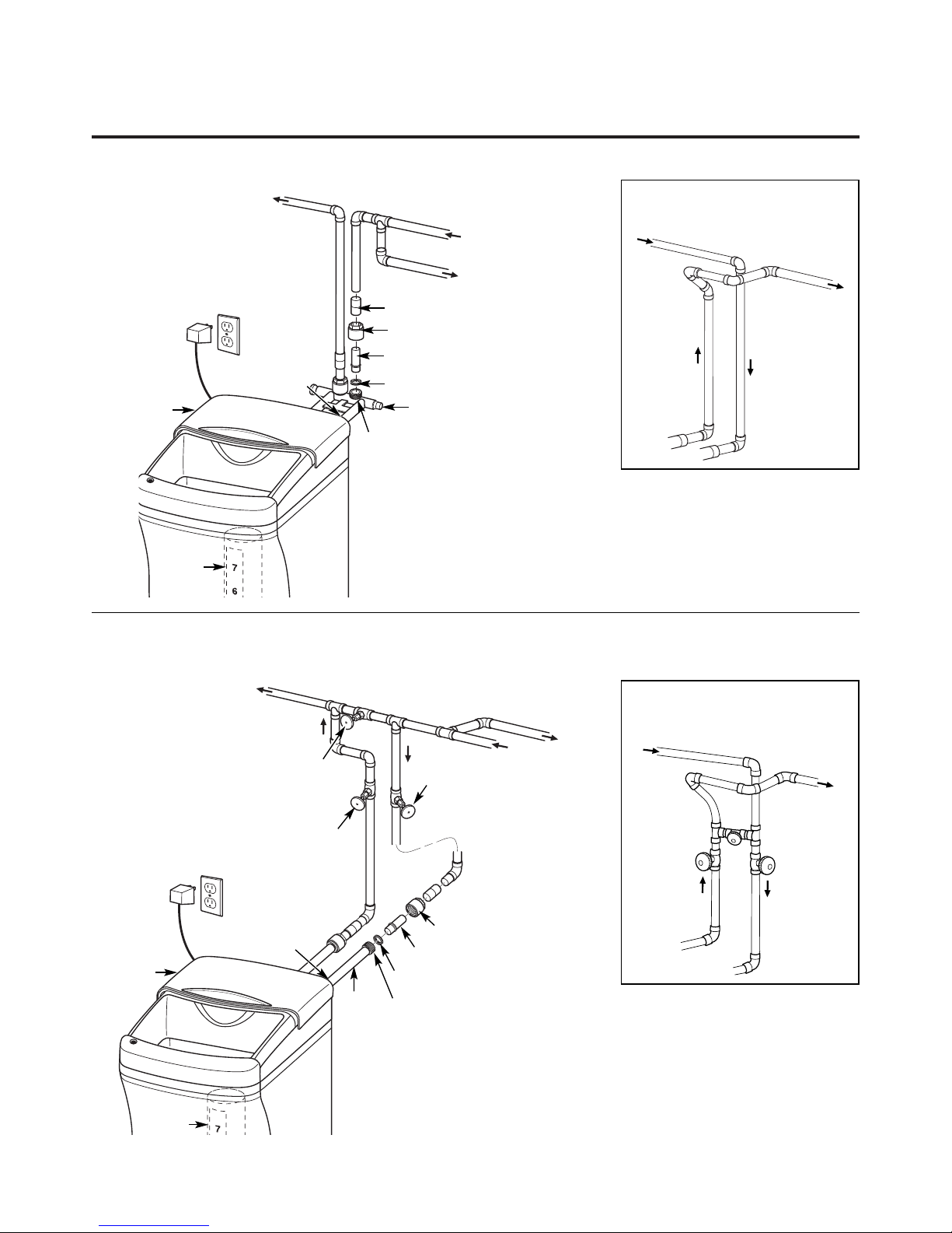
Typical Installation Illustration
Soft water
Hard water to
outside faucets
MAIN WATER PIPE
Hard water
NOTE: See Drain Hose Connections section.
24V transformer
220 -240 volt outlet
Bypass valve
Hard water to
outside faucets
Inlet valve
Outlet valve
3-Valve Bypass System
For soft water service:
• Open the inlet and
outlet valves
• Close the bypass valve
For bypass hard water:
• Close the inlet and
outlet valves
• Open the bypass valve
SALT
GOES HERE
Brinewell
INLET
Washer (2) (not supplied)
Copper tube, 3/4″ (2) (not supplied)
Installation nut (2) (not supplied)
Bypass Valve
• Pull out for soft water service
• Push in for bypass
Nut (2) (not supplied)
Copper tube, 3/4″ (2) (not supplied)
Washer (2) (not supplied)
Installation adapter (2) (see above)
INLET
Union (not supplied) (2)
Optional 3-Valve Bypass Installation Illustration
Adapters for this installation are not supplied with the softener.
Fig. 1
CROSSOVER
Use if water supply flows from the left.
Include single or 3-valve bypass.
Hard water
From softener
outlet
Soft water
To softener
inlet
Fig. 2
CROSSOVER
Use if water supply flows from the left.
Include single or 3-valve bypass.
Hard water
From softener
outlet
Soft water
To softener
inlet
MAIN WATER PIPE
Hard water
Soft water
220 - 240 volt outlet
24V
transformer
Brinewell
SALT
GOES HERE
Drain
(not shown)
Drain
(not shown)
Salt hole
cover
Salt hole
cover
Page 6
6
Step-by-step installation instructions.
■ Turn off the gas or electric supply to the water heater, in the possibility that
the water heater may be drained while draining pipes.
■
Turn off the water supply to pipes to be cut and drain the house water pipes.
■
Open both hot and cold faucets at the lowest location possible
.
NOTE:
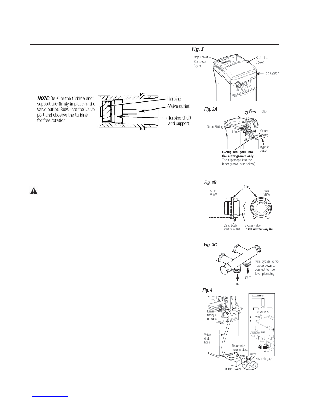
For easier installation, remove the top cover (Figure 3).
cover forward and lift up.
1. INSTALL BYPASS VALVE ( Actual bypass may differ from drawing)
• Remove top cover (fi gure 3) and remove plastic shipping plug and wire from valve outlet .
• Push the bypass valve (lubricate o-ring seals with silicone grease) into both ports of the
valve as shown in Fig. 3A.
• Snap the 2 large plastic clips in place, from the top, down as shown in Figures 3A and 3B.
Be sure they snap into place. Pull on the bypass valve to make sure it is held securely in place.
Make sure to read the the hardness bleed screw settings on page 91 of this manual
2. MOVE THE SOFTENER ASSEMBLY INTO INSTALLATION POSITION
Be sure the installation surface is level and smooth. Sharp objects under the tank may
puncture it. If needed, place the tank on a section of 2 cm thick (minimum) plywood.
Then, place shims under the plywood as needed to level the softener.
3. PLUMB “IN” AND “OUT” PIPES TO AND FROM SOFTENER
CAUTION:
Observe all of the following cautions as you connect inlet and
outlet plumbing. See illustrations on page 5.
• BE SURE INCOMING HARD WATER SUPPLY IS DIRECTED TO THE SOFTENER
VALVE INLET PORT. If house water fl ow is from the left, use a plumbing crossover as
shown in Fig. 1, page 5. If house water fl ows up from the fl oor level, turn the bypass valve
upside down as shown in Fig. 3C.
• If making a soldered copper installation, do all sweat soldering before connecting pipes
to the bypass valve. Torch heat will damage plastic parts.
• When turning threaded pipe fi ttings onto plastic fi ttings, use care not to
cross-thread.
• Use pipe joint compound on all external pipe threads.
• Support inlet and outlet plumbing in some manner (use pipe hangers) to keep the
weight off of the valve fi ttings.
4. CONNECT AND RUN THE VALVE DRAIN HOSE
IMPORTANT: If you want to attach the drain fi tting to a rigid tube, see Step 4A .
• Assemble drain fi tting as shown in Fig. 4.
• Use the provided drain hose to attach to the valve drain fi tting. To keep water
pressure from blowing the hose off, use a hose clamp to secure in place. Cut
the necessary length and use the remainder in Step 5.
• Locate the other end of the hose at a suitable drain point (fl oor drain, sump, laundry
tub, etc.) that terminates at the sewer. Check and comply with local codes.
IMPORTANT: If more drain hose is needed, it should be ordered from GE Parts.
The water softener will not work if water cannot exit this hose during
recharge.
• Tie or wire the hose in place at the drain point. High water pressure will cause it to whip
during the back-wash and fast rinse cycles of recharge. Also provide an air gap of at least
4cm between the end of the hose and the drain point. An air gap prevents possible
siphoning of sewer water into the softener, if the sewer should “back-up.”
• If raising the drain hose overhead is required to get to the drain point, do not raise
higher than 2 m above the fl oor. Elevating the hose may cause a back-pressure that could
reduce brine draw during recharge.
Page 7
8. ADD WATER AND SALT TO THE BRINE TANK
• Lift the salt hole cover. Add about 11 litres of water into the
tank. Do not add into the brinewell.
• Fill tank with NUGGET, PELLET or coarse SOLAR water softener
salt with a purity of 99.5% or higher. Do not use rock, block,
granulated and ice cream-making salts, or salt with iron-removing
additives
Maximum salt storage capacity is approxilately 45Kg.
Keep the salt hole cover closed unless servicing the unit or
refi lling with salt.
NOTE: If the softener is installed in a humid basement or other damp
area, it is better to fi ll the tank with less salt, more frequently. 25 Kg.
of salt will last for several months, depending on water hardness,
family size and water softening system model.
9. CONNECT TO ELECTRICAL POWER
To gain access to the transformer/power cord assembly, remove the
salt hole cover from the softener. Unclip the tabs on the rear of the
top cover and rotate the cover upwards to remove. DO NOT PULL
OR DISCONNECT WIRING.
• The softener works on 24 volt-50Hz electric power. The included
transformer changes standard 220 - 240 -volt AC house power to
24 volts.
Plug the transformer into a 220 - 240-volt outlet only. Be sure the
outlet is always live so it can not be switched off by mistake.
• Replace the top cover.
• Replace the salt hole cover.
7
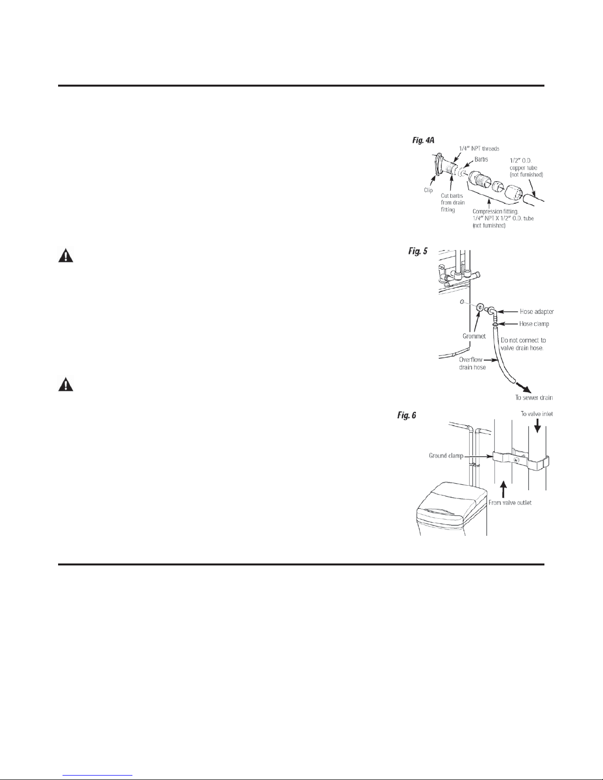
4A. CONNECTING A RIGID VALVE DRAIN TUBE
To adapt a copper drain tube to the softener, buy a compression fi tting (garden hose thread x
1/2” O.D. tube) and needed tubing from your local hardware store.
5. INSTALL THE BRINE TANK OVERFLOW FITTINGS AND HOSE
• Insert the rubber grommet into the 2 cm diameter hole in the brine tank sidewall as shown
in Fig. 5.
• Push the end of the hose adapter elbow into the grommet as shown in Fig. 5.
• Attach a length of hose (use remaining hose from Step 4) to the hose adapter elbow. Use a hose
clamp to hold it in place.
• Locate the other end of the hose at the drain point. DO NOT ELEVATE this hose higher than
the elbow on the brine tank.
IMPORTANT: DO NOT TEE OVERFLOW HOSE TO VALVE DRAIN HOSE.
NOTE: This drain is for safety only. If the cabinet (brine tank) should over-fi ll with water, the excess
is carried to the drain.
6. INSTALL GROUNDING CLAMP (not included)
DANGER:
Failure to properly attach ground clamp could result in electrical shock.
If plumbing is metal, to maintain electrical ground continuity in the house cold water piping, install
the ground clamp (not included) as shown in Fig. 6.
• Clean pipe with emery paper in the area where the clamp is to be installed.
• Install grounding clamps as shown, making sure clamps fi t freely around pipe.
• Make sure lock washer is in place.
• Handtighten screw, then one more full turn with screwdriver.
NOTE: When replacing an existing softener, also replace grounding clamps.
If removing softener completely, hard-plumb the water line with same type of pipes as the original
to assure plumbing integrity and ground continuity over the life of the home.
7. FLUSH PIPES, EXPEL AIR FROM SOFTENER, AND TEST YOUR INSTALLATION FOR
WATER LEAKS
CAUTION:
To avoid water or air pressure damage to softener inner parts, be sure to
do the following steps in exact order.
• Fully open 2 cold soft water faucets nearby the softener.
• Place bypass valve in “bypass” position by pushing the stem inward.
• Fully open the house main water pipe shutoff valve. Observe a steady fl ow from both faucets
opened in step A, above.
• Place bypass valve in the “service” position EXACTLY as follows. KEEP SOFT WATER
FAUCETS OPEN.
• SLOWLY pull or slide the valve stem (out) toward the service position, pausing several times to
allow the softener to pressurize slowly.
• After about 3 minutes, open a HOT water faucet for 1 minute, or until all air is expelled, then
close. NOTE: If water appears cloudy or has salty taste, allow to run for several more minutes, or
until clear.
• Close all water faucets.
• Check your plumbing work for leaks and fi x right away if any are found. Be sure to observe
previous caution notes.
• Turn on the gas or electric supply to the water heater. Light the pilot, if applicable.
Page 8

8
Step-by-step installation instructions.
Programming the Control
CONTROL SETTINGS REQUIRED upon installation and after an
extended power outage.
NOTES:
■ WHEN THE TRANSFORMER IS PLUGGED INTO THE
ELECTRICAL OUTLET, 12:00 PM (flashing), and an arrow is
displayed next to PRESENT TIME on the faceplate decal. The blue
indicator light will also flash. Program the control as instructed
below.
■ If - - - is flashing, use the UP button to set the correct code
F18 for GXOF18G
If you pass by the correct number, use the DOWN button. Then
press the MODE button to accept the correct model.
■ A “beep” sounds while pressing buttons for control programming.
One beep signals a change in the control display. Repeated beeps
mean the control will not accept a change from the button you
have pressed, and you should select another button.
■ To program the control, you will use the UP , DOWN and
MODE buttons.
■ Use the MODEbutton to scroll arrow to desired control function.
SET PRESENT TIME OF DAY
1. Press the MODE button until arrow
points to PRESENT TIME.
2. Press UP or DOWN button
to set. The UP button advances the time; the DOWN button moves
the time in reverse.
2. If the present time is between noon and midnight, be sure PM shows
in the display. If the present time is between midnight and noon, be
sure AM shows in the display.
NOTE: Each press of an UP or DOWN button changes the time
by one minute. Holding the button changes the time at a rapid rate.
3. When the present time is correct, press MODE to accept.
SET WATER HARDNESS NUMBER
1. Press the MODE button until
arrow points to HARDNESS.
2. Press UP or DOWN button to
set your water hardness number in the display. DOWN decreases the
hardness value. UP increases the hardness value.
NOTE: Each press of a button changes the display by 1, between 1 and
25. Above 25, the display changes 5 at a time (25, 30, 35, etc.). Holding
a button in changes the numbers at a rapid rate.
3. When the display shows your water hardness (in grains per gallon),
press MODE to accept.
NOTE: If there is clear water iron in your water supply, you will need to
increase the hardness setting by 5 for each 1 ppm of clear water iron in
your water supply.
You can get the grains per gallon (gpg) hardness of your
water supply from a water analysis laboratory. If you are on
a municipal supply, call your local water department. To calculate the
gpg hardness from German degrees divide by 0.953, to calculate gpg
hardness from French degrees divide by 1.71. If your report
shows hardness in parts per million (ppm) or milligrams per liter
(mg/l), simply divide by 17.1 to get the equivalent number of grains
per gallon.
SET RECHARGE (STARTING) TIME
1. Press the MODE button until arrow
points to RECHARGE TIME.
NOTE: A flashing 2:00 AM (factory
default) should show in the display. This is a good time for recharge to
start (takes about 2 hours) in most households because water is not in
use. HARD WATER is bypassed to house faucets during recharge.
If no change is needed, go to step 3. To change the recharge starting
time, follow step 2.
2. Press UP or DOWN button to set the desired recharge start
time. Be sure to observe the AM or PM as you did when setting the
time of day.
NOTE: Each press of a button changes the time by 1 hour. Holding the
buttons in changes the time at a rapid rate.
3. Press the MODE button to accept.
SET SALT LEVEL
1. Press the MODE button until
arrow points to SALT LEVEL.
2. Determine level of salt in brine tank
using yellow indicator on side of brine well, inside brine tank
(see illustration on page 5).
3. Press UP or DOWN button to
set the SALT LEVEL to correspond to
level on yellow indicator in brine tank.
NOTE: Each press of a button changes the
level by increments of 0.5 up to 8.0. As the number increases, the salt
level bars increase on each whole number. Lowering the salt level
below zero turns the SALT LEVEL indicator OFF.
4. Press the MODE button to accept. The display
shows the present time of day and DAYS TO
EMPTY. RECHARGE TONIGHT may appear if
unit is new.
SALT
LEVEL
PM
SALT
LEVEL
SALT
LEVEL
DAYS TO EMPTY
PM
RECHARGE TONIGHT
E
SALT
LEVEL
SALT
LEVEL
AM
SALT
LEVEL
Page 9

9
Optional Control Settings
The controller display has several options and features.
LOW SALT ALARM
The LOW SALT ALARM, when enabled,
will sound the beeper when the DAYS
TO EMPTY value is 15 days or less. To
change this setting, press and hold
the MODE button for 3 seconds. ON
(factory default) or OFF will fl ash in
the display. Press the UP ▲ or DOWN ▼ buttons to toggle this feature
ON or OFF. Press the MODE button to accept, and the display will
move to SALT EFFICIENCY.
SALT EFFICIENCY
When the SALT EFFICIENCY feature
is ON, the unit will operate at a salt
effi ciency of 4000 grains of hardness
removed per pound of salt (59fm3/
kg salt). This mode of operation
is the most effi cient setting for salt
usage, because the system will tend to
recharge more often, with less salt usage. Turning the feature OFF will
tend to lengthen the time between recharge cycles, which will provide
the most effi cient usage of water, but may use more salt. The degree of
difference between these two cycles is highly dependent on the water
usage and hardness at a particular installation.
To change the setting, press the UP ▲
or DOWN ▼ buttons to toggle
the feature ON or OFF. Press the MODE button to accept. The display
will move to SYSTEM/ELECTRONIC DIAGNOSTICS.
SYSTEM/ELECTRONIC DIAGNOSTICS
This display contains system diagnostics
information to assist in troubleshooting
problems with the system.
See page 15 for details. Press the MODE
button to return to the normal run
display.
LOST TIME SIGNAL
If time is lost on the display due to power interruption, the blue
indicator light will fl ash 4 times every second, until the present time of
day is entered.
LOW SALT SIGNAL
When the DAYS TO EMPTY drops to 15, the blue indicator light and
DAYS TO EMPTY in the display will fl ash every second and the alarm will
beep every 30 seconds (from 8:00 AM to 8:00 PM), to notify the user
that the unit is running low on salt. As soon as any button is pressed,
the alarm will stop beeping. The blue indicator light and DAYS TO
EMPTY will continue to fl ash. Once salt is added to the brine tank and
the SALT LEVEL is reset, the DAYS TO EMPTY wil l
be reset.
ERROR SIGNALS
If there is an error code detected, the
blue indicator light will fl ash 4 times
every second, the display will fl ash
Err, and the alarm will beep every 30
seconds (from 8:00 AM to 8:00 PM),
to signal that the softener requires
service. The alarm can be turned off by pressing any button, but the
blue indicator light and display will continue to fl ash.
See page 14 for information to assist in troubleshooting error codes.
Once the problem is corrected, disconnect the transformer from the
wall outlet momentarily, and plug it back in. The normal display will
appear. The motor may run for several minutes, as the unit resets.
If the problem is not corrected, the error code will reappear in 6
minutes.
BLUE INDICATOR LIGHT
Steady blue light indicates that the unit is working correctly. The light
fl ashes
when the unit needs attention from the user.
• Light fl ashes and DAYS TO EMPTY fl ashes—check salt level and add
salt as required.
• Light fl ashes and Err is in the display˜electrical problem
with system˜see page 16.
• Light will also fl ash when power to the unit has been
interrupted. Check the PRESENT TIME setting.
Programming the Control (cont.)
DAYS TO EMPTY
The words DAYS TO EMPTY and a number
are shown in the lower half of the display.
This information is shown in the normal
run display. This is to inform the user of
the number of days before the salt level in
the brine tank reaches Level 0. There will
be salt left in the salt tank, but it may not be suffi cient to fully recharge
the system. Salt should be added at this time to avoid hard water. The
value is updated daily and whenever the SALT LEVEL value is changed.
NOTE: For the fi rst several weeks of operation the DAYS TO EMPTY may
provide erratic operation. For example, the blue indicator light may
fl ash, showing that more salt is required when the actual salt level in
the tank is well above the Level 0. In some cases, the DAYS TO EMPTY
may even increase over a several week period.
It takes a couple of months for the water softener to learn your water
usage pattern. Once it does this, it will accurately determine actual
salt usage pattern. During this fi rst period, check salt level when blue
indicator light fl ashes. If the salt level in the tank is at Level 1 or above,
allow system to run. Be sure to reset your salt level indicator each time
you add salt to the system.
Page 10

10
This system conforms to NSF/ANSI 44 for the specific capacity claims as verified and substantiated by test data.
* Testing was performed using pellet grade sodium chloride as the regenerant salt.
** Efficiency rating is valid only at the lowest stated salt dosage and service flow rate. This softener was efficiency
rated according to NSF/ANSI 44.
*** Extent of iron removal may vary with conditions. The capacity to reduce clear water iron is substantiated by
independent laboratory test data.
Refer to Cleaning Iron Out of the Water Softening System section.
Step-by-step installation instructions.
Sanitizing Procedures
To complete the installation, do the following
sanitizing procedures.
Care is taken at the factory to keep your
water softener clean and sanitary. Materials
used to make the softener will not infect or
contaminate your water supply and will not
cause bacteria to form or grow. However,
during shipping, storage, installing and
operating, bacteria could get into the
softener. For this reason, sanitizing as
follows is suggested when installing.
NOTE: Sanitizing is recommended by the
Water Quality Association for disinfecting.
1. Be sure to complete all installation steps,
including programming the control.
2. Pour about 22.ml (1
1
⁄2 tablespoons) of
common 5.25% unscented household bleach
(Clorox, Linco, Bo Peep, White Sail, Eagle,
etc.) into the brinewell. Refer to illustration
on page 5.
3. IMPORTANT: Press and hold for 3 seconds
the faceplate RECHARGE button to start
an immediate recharge. RECHARGE begins
to flash in the display. The bleach will be
drawn through the water softener and out
the drain. This process takes approximately
2 hours.
4. If, after sanitization, water from the house
faucet tastes salty or has a slight color, this is
a preservative from the resin tank. Turn on
the cold soft water faucets and drain for a
few minutes or until clear.
NOTE: When the above sanitizing regeneration
is over, all remaining bleach is flushed from the
conditioner and your house COLD water supply
is fully soft immediately. However, your water
heater is filled with hard water and as hot water
is used, all remaining bleach is flushed from
the system and it will refill with soft water.
When all the hard water is replaced in the
water heater, hot only and mixed hot and cold
water will be fully soft. If you want totally soft
water immediately, after the above recharge,
drain the water heater until the water runs
cold.
WARNING:If you do drain the
water heater, use extreme care as the hot
water could cause burns. Turn the water
heater off prior to draining.
Specifications/Dimensions
GXSF18G
Rated Capacity* 5.2 mols with 0.80 kg of salt
8.6 mols with 1.7 kg of salt
12.2 mols with 4.6 kg of salt
Rated Efficiency** 6.2 mols/kg @ 0.8 kg salt dose
Amount of High Capacity Resin (kg/liters) 15.1/18
Resin Tank Nominal Size (in., dia. x height) 10 x 21
Service Flow Rate (l/min) 26.5
Water Supply Maximum Hardness (gpg) 95
Water Supply Maximum Clear Water Iron (ppm)*** 5
Water Pressure Limits (min.–max. bar) 1.4 - 8.6
Pressure Drop at Rated Service Flow (bar) 0.55
Water Temperature Limits (min.–max. °C) 4 - 49
Maximum Flow Rate to Drain (l/min) 8.3
Outlet
Inlet
8.6 cm
58.2 cm
36.8 cm
76.2 cm
Page 11

11
About the water softener system. GEAppliances.com
Service
When the water softening system is providing
soft water, it is called “Service.” During service,
hard water flows from the house main water
pipe into the water softening system. Inside the
water softening system resin tank is a bed made
up of thousands of tiny, plastic resin beads. As
hard water passes through the bed, each bead
attracts and holds the hard minerals. This is
called ion-exchanging. It is much like a magnet
attracting and holding metals. Water without
hard minerals (soft water) flows from the water
softening system and to the house pipes.
After a period of time, the resin beads become
coated with hard minerals and they have to be
cleaned. This cleaning is called recharge.
Recharge is started at 2:00 AM (factory setting)
by the water softening system control, and
consists of five stages or cycles. These are
FILL, BRINING, BRINE RINSE, BACKWASH and
FAST RINSE.
For emergency needs, hard water is available
to the home during the recharge cycles.
However, you should avoid using HOT water
because the water heater will fill with the
hard water.
Automatic Hard Water Bypass During Recharge
Fill
Salt dissolved in water is called brine. Brine is
needed to clean the hard minerals from resin
beads. To make the brine, water flows into the
salt storage area during the fill stage.
Brining
During brining, brine travels from the salt
storage area into the resin tank. Brine is the
cleaning agent needed to remove hard minerals
from the resin beads. The hard minerals and
brine are discharged to the drain.
The nozzle and venturi create a suction to
move the brine, maintaining a very slow rate
to get the best resin cleaning with the least salt.
Brine Rinse
After a pre-measured amount of brine is used,
the brine valve closes. Water continues to flow
in the same path as during brining, except for
the discontinued brine flow. Hard minerals and
brine flush from the resin tank to the drain
.
Backwash
During backwash, water travels up through
the resin tank at a fast flow rate, flushing
accumulated iron, dirt and sediments from
the resin bed and to the drain.
Fast Rinse
Backwash is followed by a fast flow of water
down through the resin tank. The fast flow
flushes brine from the bottom of tank, and
packs the resin bed.
After fast rinse, the water softening system
returns to soft water service.
Page 12

12
About the water softener system.
Breaking a Salt Bridge
Sometimes, a hard crust or salt bridge forms in
the salt storage area. It is usually caused by high
humidity or the wrong kind of salt. When the
salt bridges, an empty space forms between the
water and salt. Then salt will not dissolve in the
water to make brine.
If the brine tank is full of salt, it is hard to tell
if you have a salt bridge. Salt is loose on top,
but the bridge is under it. The following is the
best way to check for a salt bridge.
Salt should be loose all the way to the bottom
of the tank. Take a broom handle or like tool,
and carefully push it down into the salt,
working it up and down. If the tool strikes
a hard object (be sure it’s not the bottom or
sides of the tank), it’s most likely a salt bridge.
Carefully break the bridge with the tool.
Do not pound on the walls of the tank.
If the wrong kind of salt made the bridge, take
it out. Then fill the tank with nugget or pellet
salt only. In humid areas, it is best to fill with
less salt, more often to prevent a salt bridge
from forming.
A clean nozzle and venturi is needed for the
water softening system to work properly. This
small unit makes the suction to move brine
from the salt storage area to the resin tank
during recharge. If it becomes plugged with
sand, dirt, etc., the water softening system
will not work and you will get hard water.
To get to the nozzle and venturi, remove
the water softening system top cover. Be sure
the water softening system is in service cycle
(no water pressure at nozzle and venturi).
Then, while holding the nozzle and venturi
housing with one hand, remove the cap. Lift
out the screen support and screen, then the
nozzle and venturi. Wash and rinse the parts in
warm water until clean. If needed, use a small
brush to remove iron or dirt. Also check and
clean the gasket.
NOTE: Some models have a small flow plug
located in the nozzle and venturi, and/or
a small cone shaped screen in the housing.
Be sure to check and clean these parts,
if your model is so equipped.
Carefully replace all parts in the correct order.
Lightly lubricate the o-ring seal with clean
silicone grease or petroleum jelly and place in
position. Install and tighten the cap, by hand only.
Do not overtighten the cap.
Cleaning the Nozzle and Venturi Assembly
Push tool into salt
bridge to break
Pencil
mark
Broom
handle
Salt
Salt
bridge
Water level
2−5 cm
IMPORTANT: Be sure small holes in the gasket are
centered directly over the small holes in the nozzle and
venturi housing.
*Install with numbered side up, concave side down.
Cap
O-ring seal
Screen support
Screen
Screen
Nozzle & Venturi
Nozzle & Venturi
housing
Gasket
*Flow plug
*Flow plug
Page 13

13
GEAppliances.com
During normal operation, the present time of
day and AM or PM and DAYS TO EMPTY show
in the control display area. When the demand
computer determines a recharge is needed,
RECHARGE TONIGHT begins to flash in the
display along with the present time. RECHARGE
TONIGHT flashes until the next recharge start
time, then changes to RECHARGE, which flashes
until the recharge is over.
Normal Operation, Control Displays
Sometimes, a manually started recharge may
be desired or needed. Two examples:
■ You have used more water than usual
(house guests, extra washing, etc.) and
you may run out of soft water before the
next recharge.
■ The system ran out of salt.
Use one of the following features to start
a recharge immediately, or at the next preset
recharge start time.
RECHARGE TONIGHT
Touch (do not hold) the RECHARGE button.
RECHARGE TONIGHT flashes in the control
display area. A recharge will occur at the next
preset recharge start time. If you decide to
cancel this recharge, touch the same button
once more.
RECHARGE
Press and hold the RECHARGE button until
RECHARGE starts to flash in the control display
area. The water softening system begins an
immediate recharge and, when over in about
two hours, you will have a new supply of soft
water. Once started, you cannot cancel this
recharge.
Feature: Optional Recharge Controls
Feature: Memory
If electrical power to the water softening system
is interrupted, the control display is blank, and
the blue indicator light is off, but the control
keeps correct time for about 6 hours. When
power is restored, you have to reset the present
time only if the display and blue indicator light
are flashing. All other settings are maintained
and never require resetting unless a change
is desired.
If the time is flashing after a long power outage,
the water softening system continues to work
as it should to provide you with soft water.
However, recharge may occur at the wrong time
of day until you reset the control to the correct
time of day.
The control computer has a self-diagnostic
function for the electrical system (except
input power and water meter). The computer
monitors the electronic components and
circuits for correct operation. If a malfunction
occurs, an error code appears in the
control display.
The chart on Error Codes shows the error codes
that could appear and possible reasons for each
code. See Manually Initiated Electronic Diagnostics
to further isolate the defect.
Feature/Service: Automatic Electronic Diagnostics
Page 14

14
To remove an error code: 1. Unplug transformer.
2. Correct defect.
3. Plug transformer in.
4. Wait for at least 6 minutes. The error code will return if the reason for
the error code was not corrected.
NO SOFT
WATER
CONTROL SHOWS
WRONG TIME AND DAY,
AND/OR IS FLASHING.
CONTROL
DISPLAY
BLANK.
CONTROL DISPLAY SHOWS
CORRECT TIME AND DAY
AND IS STEADY.
Check electrical
power to control
(outlet, transformer,
power cable, all
connections).
Do manual
diagnostics.
NOPOWER
POWER OK
REPAIR AS
NEEDED
CONTROL
DEFECTIVE
Do manual
diagnostics to
verify proper
function.
Electrical power was off.
Reset the correct time of
day.
Investigate reason for
power loss.
About the water softener system.
Service: Electronic Demand Time Features and Service
If you are not getting soft water, and an error
code is not displayed, use the procedures below
to find the problem. First make the following
visual checks.
VISUAL CHECKS:
1. Is there electrical power to the outlet the
water softening system transformer is
plugged into?
2. Is there sufficient salt in the storage tank?
3. Is the softener bypass valve directing water
for soft water service?
4. Is the valve drain hose open to the drain,
not more than 2m above the softener, and
unobstructed?
If you do not find a problem with the visual checks,
continue below.
Service: Timer/Softener, Service Checkout Procedure
ERROR CODE
DISPLAYED ERR 01 ERR 02 ERR 03 ERR 04 ERR 05
POSSIBLE DEFECT • Motor • Position • Motor • Position • Control
inoperative switch inoperative switch or
or wiring wiring
harness harness
• Wiring • Control • Control • Control
harness or
connection
to switch
• Position
switch
• Control
Page 15

15
GEAppliances.com
1. To enter diagnostics, press and hold
the MODE button for 3 seconds until
the Low Salt Alarm screen shows.
2. Press the MODE button 2 times to
advance through Low Salt Alarm
and Salt Efficiency options. See
Programming the Control for details
on these two options.
3. OPERATION OF DIAGNOSTICS
• Valve Position – Press the RECHARGE button to
initiate a recharge cycle. Press again to manually index
valve to next position. See Service: Manually Advance
Recharge Check for details.
0 – Service
1 – Fill
2 – Brine
3 – Backwash
4 – Fast Rinse
• Motor Operation – Two dashes will circulate around
when motor should be running.
• Position Switch Operation –
– Closed – valve rotating to next position
– Open – valve in position, service, fill, brine, etc.
• Water Meter – Indicates whether water is flowing
through valve.
– 000 indicates no water is flowing through the valve
– Open nearby soft water faucet
– 000 to 199(continual) shows water is flowing.
Display repeats for each gallon of water passing through the
meter. Control will beep at every gallon. (1 gallon= 3.78 litres)
– If there is no reading in the display, with faucet
open, check the sensor. Pull the sensor from the
valve outlet port, and pass a small magnet in front
of the sensor. Counter should index in the display.
If counter does not index, check to make sure
harness is connected to board properly. If there is
a reading in the display, there may be a problem
associated with the turbine. Turn off water supply,
close the by-pass valve, and disconnect by-pass valve
from valve body. Check turbine for binding or
restriction due to debris. If this does not correct
the problem, the Timer, Sensor, or Turbine may
require replacement.
4. Historical data about the softener is available.
• Press and hold the UP button to display the number
of days this control has had electrical power applied.
• Press and hold the DOWN button to display the
number of recharges initiated by this control since the
model code number was entered.
5. Press the MODE button to return to normal operation
and display.
Service: Set Model (F) Code
1. To change or check model code, first press and hold the
MODE button for 3 seconds until the Low Salt Alarm
screen shows.
2. Press and hold the MODE button again
for 3 seconds. A display with at
the top will appear.
3. Press the UP or DOWN buttons
to select the correct model code.
F18 = GXOF18G
4. Press the MODE button one time to return to normal
operation and display. If the model code was changed:
• the display will go blank momentarily, then display the
model code entered.
• the display will then return to the set present time
display, and the blue indicator light will flash. The
control will have to be reprogrammed. See Programming
the Control.
NOTE: If the control is left in any of the above diagnostic
displays, or a flashing display when setting time, hardness,
etc., it will revert back to the normal display in 4 minutes.
Service: Manually Initiated Electronics Diagnostics
SALT
LEVEL
SALT
LEVEL
SALT
LEVEL
Water meter
Valve
position
Position
switch
Motor
Motor
Turbine
Turbine support
and shaft
Sensor
housing
Position
switch
Valve
outlet
SALT
LEVEL
H45
Page 16

16
About the water softener system.
NOTE: The control display must show a steady
time (not flashing).
1. Press the RECHARGE button and hold in
for three seconds. RECHARGE begins to flash
as the water softening system enters the fill
cycle of recharge. Remove the brinewell
cover and, using a flashlight, observe fill
water entering the brine tank. If water does
not enter the tank, look for an obstructed
nozzle, venturi, fill flow plug or brine tubing.
See Care and Cleaning of the Water Softener
System section.
2. After observing fill, press the RECHARGE
button to move the water softening system
into brining. A slow flow of water to the drain
will begin. Verify brine draw from the brine
tank by shining a flashlight into the brinewell
and observing a noticeable drop in the liquid
level over an extended period of time.
NOTE: Be sure a salt bridge is not preventing
water from contacting salt. See Care and
cleaning of the water softening system section.
If the water softening system does not draw brine,
check:
■ nozzle and/or venturi dirty or defective.
■ defective nozzle and venturi seal.
■ nozzle and venturi not seated properly
on gasket.
■ other inner valve defect (rotor seal, rotor
and disc, wave washer, etc.).
■ restricted drain (check drain fitting and
hose).
NOTE: If water system pressure is low, an
elevated drain hose may cause back pressure,
stopping brine draw.
3. Again, press the RECHARGE button to move
the water softening system into backwash.
Look for a fast flow of water from the drain
hose. A slow flow indicates a plugged top
distributor, backwash flow plug or drain hose.
4. Press the RECHARGE button to move the
water softening system into fast rinse. Again
look for a fast drain flow. Allow the water
softening system to rinse for a few minutes
to flush out any brine that may remain in
the resin tank from the brining cycle test.
5. To return the water softening system to
service, press the RECHARGE button.
Service: Manually Advance Recharge Check
Page 17

17
Care and cleaning of the water softening system. GEAppliances.com
Brine (salt dissolved in water) is needed for
each and every recharge. The water for making
brine is metered into the salt storage area by
the water softening system valve and control.
However, you must keep the tank supplied
with salt.
When to refill with salt: If the blue indicator
light and DAYS TO EMPTY are flashing, there is
less than 15 days supply of salt. Refill with salt.
In humid areas it is best to refill with less salt
and more often, to avoid the forming of a salt
bridge, see page 12. After adding salt,
remember to reset the SALT LEVEL in the
control, see page 8. Never allow the salt level
to drop below zero on the yellow indicator
before you refill it. Without enough salt, you
will soon have hard water.
Use clean water softening salts only, at least
99.5% pure. NUGGET, PELLET or coarse
SOLAR salts are recommended. Do not use rock,
block, granulated or ice cream making salts.
They contain dirt and sediments, or mush and
cake, and will create maintenance problems.
CAUTION: Water softening salt with
iron removing additives: Some salts may have
an additive to help the water softening
system handle iron in the water supply.
Although this additive may help to keep the
water softening system resin clean, it may
also release corrosive fumes that weaken
and shorten the life of some water softening
system parts.
Checking the Salt Storage Level and Refilling
Your water softening system takes hardness
minerals (calcium and magnesium) out of
the water. Also, it can control some (see the
Specification Guidelines section) “clear water”
iron. With clear water iron, water from a faucet
is clear when first put into a glass. After 15 to
30 minutes, the water begins to cloud or turn
rust colored. A water softening system will not
remove any iron that makes the water cloudy
or rusty as it comes from the faucet (called red
water iron). To take red water iron out of water,
or over the maximum of clear water iron,
an iron filter or other equipment is needed.
If your water supply has clear water iron,
periodic resin bed cleaning is needed.
Clean the bed at least every six months, or more
often if iron appears in the soft water between
cleanings.
IMPORTANT: It is important to mix the resin bed
cleaner with water (following the manufacturer’s
instructions), pour it into the brinewell tube
(see page 5) and recharge the softener
immediately. Do not pour the resin bed cleaner
in with the salt, as it will not be as effective in
cleaning the resin, and can cause damage to
the softener if it is left in the brine tank for an
extended period due to the corrosive gases that
are formed.
Cleaning Iron Out of the Water Softening System
Page 18

18
Troubleshooting Tips
Save time and money! Review the chart on this
page first and you may not need to call for service.
Problem Possible Causes What To Do
No soft water Faucet or fixture where sample was •
To conserve salt, the installer
may have isolated some fixtures
taken not plumbed to soft water.
(outside faucets, toilets, etc.)
from soft water. From the outlet
NOTE:
Be sure sample is from a faucet of the water softening system, trace the water flow path,
that does not mix soft and hard water. in house plumbing. If soft water is not directed to a faucet
For example, a single lever kitchen faucet, or
fixture where wanted, consult a plumber.
if the cold side is plumbed to hard water.
No salt in the brine tank or • Check for a salt bridge or, if the
tank is empty, refill with
salt bridged recommended salt. Press (for 3 seconds) the RECHARGE
button to start an immediate recharge and restore
soft water supply.
Transformer unplugged at wall outlet or
• Check for a loss of electrical power to the water softening
power cable to softener not connected. system, due to any of these conditions and correct as needed.
Fuse blown or circuit breaker popped With the power supply restored, observe the faceplate time
on circuit to electrical outlet. display and read Programming the Control section.
Electrical outlet on a circuit that can
NOTE: The electrical outlet for the softener should be continuously
be switched off
live
so it cannot be accidentally switched off.
Manual bypass valve in bypass position • Be sure the bypass valve stem
is positioned properly, with the
knob in the OUT position. Observe i
nstructions on the decal
at the end of the stem. Check the position of bleed screw.
Valve drain hose pinched, plugged, •
Any restriction in this drain hose
may prevent proper
elevated too high or otherwise
operation of the
nozzle and venturi and reduce or prevent
restricted brine draw during recharge.
Nozzle and venturi dirty, incorrectly • Refer to Cleaning the Nozzle and Venturi Assembly
instructions.
assembled or damaged
With water pressure to the
water softening system off, take
the nozzle assembly apart. Inspect, clean and replace as
needed. Any foreign particle(s), scratches, nicks, etc., in the
passages can
prevent operation. Be sure holes in the gasket are
centered over holes in the housing.
NO SOFT WATER – Most Common Problems:
Check the following before calling for service:
•
Not enough salt—should be at least 1/3 full.
•
Bypass valve in “Bypass” position—knob should be in the “OUT” (service) position.
•
Hardness setting too low. Check hardness setting and adjust. Verify hardness of
supply water—from local water company, water test or call the GE Answer Center.
•
Salt Bridge—salt solidifies above water level so that brine water is not in contact
with salt. See the Breaking a Salt Bridge section.
Before you call for service…
Page 19

19
Problem Possible Causes What To Do
Water hard sometimes Using hot water while the water • Avoid using hot water during water softening system
softening system is regenerating recharge because the water heater will refill with hard water.
See Automatic Hard Water Bypass During Recharge section,
page 11.
Control HARDNESS number setting • Press the MODE button until arrow points to HARDNESS.
too low Be sure the number shown is the same as the actual grains
per gallon hardness of your water supply. See the
Programming the Control section if a change in the setting
is needed.
Grains of hardness in your water •
Water hardness can change
over time, especially in well water.
supply have increased To check, have the water tested by a water analysis laboratory
or call your local water department. Adjust the HARDNESS
number setting as needed.
Water feels slippery Absence of hardness minerals • This is normal. Hardness in water gives it the abrasive feel
after installation of you may have been accustomed to. The slippery feel is the
water softening system clean feel of soft water.
Water softening system Water softening system is a • Does not use much salt to regenerate—very efficient.
not using any salt “demand” unit
Possible salt bridge • See the About the Water Softener System section, page 12.
Possible plugged nozzle and venturi • See the About the Water Softener System section, page 12.
Water is blue color Acidic water in copper plumbing • Have the water tested at once.
after water softening
system was installed
Water softening system Meter turbine stuck • See the Service: Manually Initiated Electronics Diagnostics
not regenerating section for troubleshooting procedures, page 15.
• Call for service.
Sensor wire not plugged into • See the Service: Manually Initiated Electronics Diagnostics
the control section for troubleshooting procedures, page 15.
• Call for service.
No power to unit • Check the circuit breaker or fuses.
Mechanical defect • Call for service.
Cloudiness on glassware Combination of soft water and • This is called etchingand is permanent. To prevent this
(automatic dishwashers) too much detergent from happening, use less detergent if you have soft water.
Wash glassware in the shortest cycle that will get them clean.
Excessive/high level Valve drain hose pinched, • Any restriction in this drain hose may prevent proper
of water in brine tank plugged, elevated too high operation of the nozzle and venturi and reduce or prevent
or otherwise restricted brine draw during recharge.
Nozzle and venturi dirty, incorrectly • See the Cleaning the Nozzle and Venturi Assembly section,
assembled or damaged page 12. With water pressure to the water softening system
off, take the nozzle assembly apart. Inspect, clean and
replace as needed. Any foreign particle(s), scratches, nicks,
etc., in the passages can prevent operation. Be sure holes
in the gasket are centered over holes in the housing.
GEAppliances.com
Page 20

20
Problem Possible Causes What To Do
Salty tasting or Unit not sanitized • Complete the Sanitization Procedureson page 10.
brown/yellow colored
• At completion of recharge cycle(approx. 2 hrs), run water
water after installation
from faucets to purge the salty water.
Low water pressure • Check pressure; should be minimum1.4 Bar.
Restricted drain hose • Clean and reconnect hose.
• Check for kinks in drain line.
Brown/yellow Unit was idle for a period of time • Complete the Sanitization Procedures on page 10.
colored water
Resin beads showing Cracked distributor • Call for service.
up in drinking water
and sink
Sounds you might hear Running water from the unit •This is normal.
into a drain during recharge
Water has air bubbles Air in system after installation •Will go away after it runs for a while.
and is cloudy
Error Code on control Wiring may have worked loose • See page 14 for details.
in the control
• Unplug transformer.
• Remove control cover, release clips on side.
• Check for loose/incorrect wiring connections to electronic
board or switch. Reconnect as required.
• Reassemble control cover.
• Plug in Transformer.
• Wait six minutes for Error Code to reappear.
• If Error Code reappears, call for service.
Troubleshooting Tips
Before you call for service…
Blue light flashing
When power applied Control needs to be programmed • See the Programming the Control section, page 8.
to the system (a power outage may have occurred)
If “DAYS TO EMPTY” Low salt level, less than 15 days • Fill with salt.
is flashing
•Reset salt level.
If “Err” in display Electrical problem with system • See page 14 for details.
•See procedure above, Error code on control.
Page 21

12/16/04 (Rev. A)
SmartWater
¥
Water Softening Systems
Model GXOF18G
PERFORMANCE DATA SHEET
This softener conforms to NSF/ANSI 44 for the specific performance claims as verified and substantiated by test data.
This model is efficiency rated. The efficiency rating is valid only at the minimum stated salt dose. It has a demand
initiated regeneration (D.I.R.) feature that complies with specific performance specifications intended to minimize the
amount of regenerant brine and water used in its operation. The softener has a rated salt efficiency of not less than
3350 grains of total hardness exchange per pound of salt (based on sodium chloride) and shall not deliver more salt
than their listed rating. The rated salt efficiency is measured by laboratory tests described in NSF/ANSI Standard 44.
These tests represent the maximum possible efficiency that the system can achieve. Operational efficiency is the actual
efficiency after the system has been installed. It is typically less than the efficiency due to individual application
factors including water hardness, water usage, and other contaminants that reduce the softener’s capacity. Use clean
water softening salts only, at least 99.5% pure. For best results use nugget, pellet or coarse solar salts. This system is
not intended for treating water that is microbiologically unsafe or of unknown quality without adequate disinfection
before or after the system. Refer to Use and Care Manual for further details on installation and maintenance, user’s
responsibilities, parts and service, and further restrictions, or limitations to the use of the product. GE complies with
applicable local warranty laws via its authorized distributors and re-sellers.
SPECIFICATIONS
Rated Service Flow Rate 26.5 L/min
Pressure Drop at Rated Service Flow Rate 0.55 Bar
Rated Capacity for Softening
5.2 mols with 0.8 Kg of salt
8.6 mols with 1.7 Kg of salt
12.2 mols with 4.6 Kg. of salt
Rated Efficiency 6.2 mols/Kg @ 0.8 Kg of salt
Iron Reduction1 5 ppm
Min.-Max. Working Pressure 1.4-8.6 Bar
Min.-Max. Operating Temperature
4-49 qC
Max. Flow Rate to Drain During
Regeneration Cycle
8.3 L/min
1
Tested by a qualified independent laboratory against accepted industry protocol.
PERFORMANCE CLAIMS
Contaminant Influent Challenge Level
Maximum Allowable
Product Water level
Barium 10±10% mg/L 2.0mg/L
Radium 226/228 25 pCi/L 5 pCi/L
General Electric Company
Appliance Park, Louisville, KY 40225
www.geappliances.com
 Loading...