

Page 1

GE SmartWater
Ô
Water Filtration System
INSTALLATION INSTRUCTIONS
Models GNUT05Z, GXUT05Z, GNUV10Z, GXUV10Z, GNUL30Z,
GXUL30Z & GXEM01Z
TABLE OF CONTENTS: Page #
Important Installation Recommendations 1
Tools and Materials Required for Installation 2
Step-by-Step Installation Instructions
— Feed water supply 3
— Electronic faucet installation 4
— Wall mounting 5
— Tubing connection 5
— Battery installation 5
— Filter cartridge installation 5
Parts List 6, 7
IMPORTANT INSTALLATION RECOMMENDATIONS
Read entire manual. Failure to follow all guides and rules could cause personal injury or property damage.
• Check with your local public works department for plumbing codes. You must follow their guides as you install the Water Filtration
system.
• Use the Water Filtration system on a potable, safe-to-drink, home COLD water supply only. The filter cartridges will not purify water
or make unsafe water safe to drink. DO NOT use on HOT water (100°F. max).
• Protect the Water Filtration system and piping from freezing. Water freezing in the system will break it.
• Your Water Filtration system will withstand up to 125 psi water pressure. If your house water supply pressure is higher than 100 psi
during the day (it may reach higher levels at night), install a pressure reducing valve before the system.
WARNING: Do not use with water that is microbiologically unsafe or of unknown quality without adequate disinfection before
or after the system. GNUL30Z and GXUL30Z are certified for cyst reduction and may be used on disinfected water that may
contain filterable cysts. The water should be tested periodically to verify that the system is performing satisfactorily.
Small parts remaining after the installation could be a choke hazard. Discard safely.
7178977 (10-97) 215C1001P003-2 For Use and Care questions call: GE Answer Center® 800.626.2000
Pub. No. 49-5809-2 GENERAL ELECTRIC COMPANY, Appliance Park, Louisville, KY 40225
GNUT05Z, GXUT05Z, GNUV10Z,
GXUV10Z, GNUL30Z, and GXUL30Z are
tested and certified to ANSI/NSF Standard
42 for particulate reduction Class I,
chlorine reduction Class I and taste and
odor reduction.
GNUV10Z and GXUV10Z are tested and
certified to ANSI/NSF Standard 53 for
volatile organic chemical reduction.
GNUL30Z and GXUL30Z are tested and
certified to ANSI/NSF Standard 53 for cyst,
turbidity and lead reduction.
NSF
®
1
Page 2
2
TOOLS AND MATERIALS REQUIRED FOR INSTALLATION
• Slotted and Phillips screw drivers
• Pliers and adjustable jaw wrench
• Hand or battery powered drill and 1⁄4² bit (saddle valve installation)
• Electric drill and a drill bit to drill a 1⁄4²hole (type as required) if a mounting hole is needed for the faucet
CAUTION: To avoid damaging the sink, consult a qualified plumber or installer for drilling procedures. Special drill bits
may be needed for porcelain or stainless steel.
• Contents included with the product:
— Water filter assembly, including mounting bracket and screws
— Literature (installation instructions, owner’s manual, product data sheet, and owner product registration card)
— Water supply/saddle valve
— Filtered water faucet, for sink or countertop mounting including an electronic indicator faucet base and battery pack
— 3⁄8²tubing and fittings to make all needed connections
— Pipe joint sealant (Teflon Tape*) for fittings
— Sump wrench
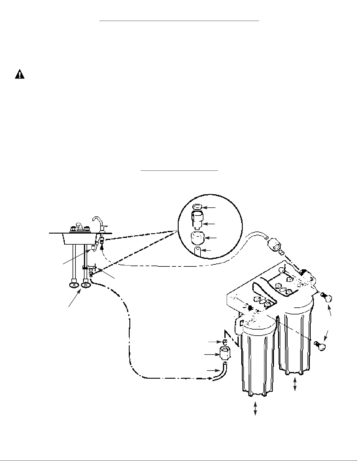
Fig. 1
Filtered water faucet
Sink
Battery pack
Hot
Shutoff valve
NOTE: To change the filter
cartridge, you must turn off
the water. A nearby shutoff
valve is convenient. Most
sinks already have shutoff
valves on the supply pipes.
Cold
Water supply/saddle valve
Washer
Adapter
Nut
Water
in
Water
out
Tubing
Insert
Mounting
screw (2)
Filter I
NOTE: Be sure to allow a minimum space of 1-1⁄2² under the
system for removing the sumps, to change the cartridges.
*Teflon Tape is a Registered Trademark of Dupont
Filter II
Nut
Tubing
INSTALLATION OVERVIEW
Locate the drinking water system on the cold water supply pipe, under the kitchen and/or bathroom sink, to filter the cold drinking water.
Page 3

STEP-BY-STEP INSTALLATION INSTRUCTIONS
FEED WATER SUPPLY
Check and comply with local plumbing codes as you plan, then install a cold feed water supply fitting. For new home installation using
standard plumbing fittings, see Fig. 2A below. A typical installation for existing homes using the saddle valve is shown in Fig. 2B below.
A. PREFERRED INSTALLATION
1. Turn off the cold water supply.
2. Complying with plumbing codes, install a fitting on the cold
water pipe to adapt 1⁄4²OD tubing. A typical connection is
shown in Fig. 2A. Make sure a shutoff valve is used.
B. OPTIONAL HOME INSTALLATION
When codes permit
NOTE: Codes in the state of Massachusetts require installation by
a licensed plumber and do not permit the use of the saddle valve.
For installation, use plumbing code 248-CMR of the
Commonwealth of Massachusetts.
1. Turn off the cold water supply and attach saddle valve as
shown in Fig. 2B.
DANGER: To protect yourself from serious injury or fatal
shock, use a battery powered hand drill only to make the
hole. Do not use an electric drill.
2. Close the water supply/saddle valve by turning the handle
clockwise.
3. Open the main water supply valve and several house faucets to
purge air from the system. Close faucets when water runs
smoothly.
3
Fig. 2B.
OPTIONAL WATER SUPPLY CONNECTION
(using saddle valve)
TYPICAL LOCATION
PREFERRED WATER SUPPLY CONNECTION
(using compression fitting)
Pre-drill
1⁄4² hole
Seal—make sure
the seal is in place
Clamp X
Nut (2)—not
required if
holes in
clamp are
threaded
Valve
Handle
Nut
Cold
water
1⁄4²compression fitting
Insert
Cold
water
pipe
1⁄4² tubing to inlet
Ferrule
Ferrule
Insert
Use to connect
the tubing
❵
Clamp Z
Fig. 2A.
Page 4

ELECTRONIC FAUCET INSTALLATION
Be sure there is room underneath the sink to make the needed
connections. Select one of the following places to install the faucet:
—IN an existing sink spray attachment or soap dispenser hole
—IN a hole to be drilled in the sink top
—IN a hole to be drilled in the countertop, next to the sink
NOTE: Looking at Fig. 3D, be sure the faucet base will fit flat against
the surface at the selected location so the gasket will seal. The base may
have to be angled sideways or diagonally.
1. If drilling is needed, make a 1-1⁄4² dia. hole. Be sure to use the
proper procedure for drilling porcelain or stainless steel. Special
drill bits may be needed.
2. Looking at Fig. 3A, insert a screw into the NON-SLOTTED base
mounting hole. Turn a flat nut a few turns onto the screw.
3. Position the base gasket over the mounting hole. Set the base on
the gasket, routing the leadwire through the mounting hole.
Holding the flat nut under the sink with one finger, tighten the
screw until just snug.
4. Turn the remaining flat nut a few turns onto the other screw.
Position the screw in the slotted base mounting hole and tighten
until snug. Make sure the gasket position is properly aligned and
carefully tighten both screws until the base is held firmly in place.
Do not overtighten and break the base.
5. Assemble the top faucet base and hex nut onto the faucet stud
(Fig. 3C). Tighten the nut until snug.
6. Insert washer into tubing adapter. Securely tighten to faucet stud.
7. Put a few wraps of Teflon Tape* on the end of the faucet stud.
Using the plastic washer, turn the tubing adapter onto the faucet
stud and tighten securely.
8. Feed the length of 3⁄8² OD tubing from the bottom, up through
the faucet base. Connect to the tubing adapter as shown
in Fig. 3C., tightening the compression nut securely.
9. Remove the short shipping tube and insert the spout into the
faucet body.
10. Lower the faucet assembly and lock into place on the faucet base.
Fig. 3C.
Fig. 3A.
Fig. 3B.
Fig. 3D.
Faucet
base
Nut (2)
Screw (2)
Washer
Hex nut
Top faucet base
Faucet
Lever
Spout
Base leadwire connector
(to battery pack)
1-1/4² dia. mounting
hole in sink or
countertop
Gasket
Faucet
base
Faucet stud
Compression
nut
Tubing
adapter
3/8² tubing, (run
to Filter 2 outlet)
Faucet base
Compression
nut
TOP VIEW
ASSEMBLED
Screw (2)
Nut (2)
*Teflon Tape is a Registered Trademark of Dupont.
4
Page 5

MOUNTING BRACKET TO CABINET WALL
The bracket can be used as a template for marking the location of the mounting
screws. When determining the location of the bracket make sure you leave 1-1⁄2²
to 2² of free area under the sumps to allow for sump removal and enough space on
either side to make the tubing connections.
MAKE TUBING CONNECTIONS
1. Run the length of 3⁄8² tubing, connected to the bottom of faucet, to the filter
system outlet, Fig.1 on page 2. Allow enough slack in the tubing to be able to
place the system on the floor in front of the sink. Measure and cut the end of
the tubing square.
2. Slide a compression nut onto the end of the tubing and push a tubing insert
into the tubing.
3. Connect the tubing and tighten the compression nuts securely.
4. Repeat the preceding steps to connect a length of tubing between the filter
system inlet and the water supply/saddle valve, Fig. 1 on page 2.
BATTERY PACK INSTALLATION AND CONNECTION
1. In a dry location, within reach of the electronic base 3¢ leadwire, select a place for
the battery pack (see Fig. 1 on page 2). The battery pack attaches to most surfaces,
using the included “sticky-back” Velcro™ strip.
2. The battery pack uses two size “AA” batteries. Check to be sure they are
installed correctly. Then, remove the paper backing on the Velcro™ strip and
secure the pack in place.
3. Fasten electronic base leadwire and battery pack connector together.
FILTER CARTRIDGE INSTALLATION OR REPLACEMENT
CAUTION: Never remove sumps with water pressure in the
filtration system.
1. Close the water supply/saddle valve (Fig. 1 and 2A) to the filter. Press the vent
valve on the top of the Filter I head to relieve pressure in the system, Fig. 5, or
open the filtered water faucet.
2. Turn the sump off of the filter head as shown (use the sump wrench provided).
Be careful, the sump is full of water. Locate and save the large o-ring seal.
Remove and discard the used filter cartridge.
3. Be sure the inside of the sump is clean. Thoroughly wash with hot, soapy water
and rinse.
Fig. 4
Fig. 5
Vent valve
Filter I
Filter I
Filter II
Filter II
O-ring seal
Cartridge
Sump
Sump
Sump
Mounting
screws
Tubing
connector
Tubing
connector
Mounting
bracket
TURN SUMP
TO INSTALL
TURN SUMP
TO REMOVE
Head
Bracket
Sump
4. Remove the wrapper and labels from the new filter cartridge and insert the
filter cartridge in the sump. Some cartridges fit either
way, while others fit only one way. Observe markings on the end of the cartridge. The sediment/taste and odor filter cartridge should
always be placed in the Filter I location.
5. Lightly lubricate the o-ring seal, in the sump, with clean silicone grease. Be sure it is fully seated in its groove.
6. Hold the sump up to the filter head, aligning the center hole in the cartridge with the protrusion on the bottom of the head.
NOTE: If the sump will not tighten up to the head, you may have the cartridge in upside down. Take the cartridge out and check the
markings on the end of the cartridge for correct orientation.
7. Being careful not to cross-thread, turn the sump onto the filter head and hand tighten securely (see Fig.4).
8. Repeat steps 2 through 7 for the other filter.
9. Open the filtered water faucet. Then, slowly open the water supply/saddle valve and allow the filter housing to fill. While it is filling,
press the filter vent valve to release air in the filter.
10. Close the filtered water faucet. Then, check for leaks between the sump and the head.
NOTE: If leaking, turn off the water supply and open the filtered water faucet, or press the vent valve to depressurize the filter. Then,
disassemble the filter and check the o-ring for cuts, flat spots, etc., and sealing surfaces for foreign material. Clean the o-ring and lubricate
with clean silicone grease. Carefully press into the groove in the sump.
11. Remove and install two new “AA” alkaline batteries in the battery pack. Removing the batteries or momentarily disconnecting the
leadwires resets the six month electronic base timer.
12. The filter cartridges contain activated carbon, a black powder. When new, open the filtered water faucet for ten minutes to allow
fine, harmless carbon particles to purge from the cartridge. Air suspended in the water may also cause a “cloudy” appearance. This
air is harmless and should dissipate quickly.
5
7-9⁄16²
I-1⁄2²
to 2²
Sump
wrench
To
loosen
Page 6

6
68
53
Page 7

GENERAL ELECTRIC PARTS CATALOG
REF. NO. PART NO. PART DESCRIPTION
0001 WS02X10001 SCREW #10-14 X 3/4² 8 8 8 8 8 8 8
0002 WS28X10001 BRACKET MOUNTING 1 1 1 1 1 1 1
0003 WS22X10008 NUT 3/8² TUBE 2 2 2 2 2 2 2
0004 WS22X10007 INSERT 3/8² TUBE 2 2 2 2 2 2 2
0005 WS02X10003 SCREW #10-14 X 1/4² 2 2 2 2 2 2 2
0006 WS22X10002 ELBOW 3/8² NPT X 3/8² 2 2 2 2 2 2 2
0007 WS19X10001 HEAD 1 1 1 1 1 1 1
0008 WS03X10001 O-RING 3-3/8² X 3-5/8² 2 2 2 2 2 2 2
0009 WS30X10001 SUMP 2 2 2 2 2 2 2
0010 WS22X10003 NIPPLE 3/8² NPT X 1-1/2² 1 1 1 1 1 1 1
0011 WS19X10002 HEAD ASM. W/VENT 1 1 1 1 1 1 1
0012 WS07X10008 TUBING 3/8² X 20 FT–WH 1 1 1 1 1 1 1
0013 WS24X10001 VENT ASM. 1 1 1 1 1 1 1
0014 WS02X10004 NUT 3/8² 2 2 2 2 2 2 2
0015 WS03X10003 ADAPTER TUBING 2 2 2 2 2 2 2
0016 WS03X10002 WASHER 2 2 2 2 2 2 2
0017 WS15X10008 SADDLE VALVE /SUPPLY 1 1 1 1 1 1 1
0018 WS15X10002 FAUCET ASM. 1 1 1 1 1 1 1
0019 WS10X10001 BASE FAUCET, TOP 1 - - - - - -
WS10X10008 TOP FAUCET BASE BLACK - 1 1 1 1 1 1
0020 WS02X10007 SCREW #6-32 X 1-3/8² 2 2 2 2 2 2 2
0021 WS10X10002 BASE FAUCET KIT 1 1 1 1 1 1 1
0022 WS02X10008 NUT 2 2 2 2 2 2 2
0023 WS08X10003 GASKET FAUCET 1 1 1 1 1 1 1
0024 WS06X10001 HOLDER BATTERY 1 1 1 1 1 1 1
0025 FXUV FILTER - - 1 1 - - 1
FXUT FILTER - 1 - 1 - 1 -
FXUS FILTER 1 1 1 1 1 1 1
FXUL FILTER 1 - - 1 1 - 0200 WX5X140 WRENCH SUMP-ADJ. 1 1 1 1 1 1 1
0999 49-5809-2 PM INSTRUCTION INSTALL 1 1 1 1 1 1 1
49-5804-2 PM MANUAL USE & CARE 1 1 1 1 1 1 1
7
G G G G G G G
N N N X X X X
U U U E U U U
L T V M L T V
3 0 1 0 3 0 1
0 5 0 1 0 5 0
Z Z Z Z Z Z Z
0 0 0 0 0 0 0
1 1 1 1 1 1 1
Page 8

8
Page 9

13
 Loading...