

Page 1
Installation
Electric Dryer
Instructions
I Call 800.GE.CARES 1800.432.2737) visit Web site at:
BEFORE YOU BEGIN
Readthese instructions completely and
carefully.
. IMPORTANT- sovethese instructions
for Iocol inspector's use.
, IMPORTANT = Observe oll governing
codes ond ordinonces.
, Note to Installer- Be sure to leove these
instructions with the customer.
, Note to Customer- Keep these instructions
with your Owner's Manual for future
reference.
, Before the old dryer is removed from service
or discorded, remove the dryer doon
, Service informotion ond the wiring diogrom
are Iocoted in the control console.
, Do not ollow children on or in the opplionce.
Close supervision of children is necessory
when the opplionce is used neor children.
,Instoll the dryer where the temperoture is
above 50°F for satisfactory operation of
the dryer control system.
, Product foilure due to improper instollotion
is not covered under the Vorronty.
Questions?
In Canada, call 1.800.561.3344 or visit www.GEAppliances.ca
WARNING RISK OF FIRE
, To reduce the risk of severe injury or deoth, follow oll instollotion
instructions.
, Clothes dryer instollotion must be performed by o quolified instollen
,Instoll the clothes dryer occording to these instructions ond in
occordonce with Iocol codes.
, This dryer must be exhousted to the outdoors.
, Use only rigid metol 4" diometer ductwork inside the dryer cobinet ond
use only UL opproved tronsition ducting between the dryer ond the home
duct.
, DO NOT instoll o clothes dryer with flexible plostic ducting moteriols.
If flexible metol (semi-rigid or foil-type) duct is installed, it must be
UL listed ond instolled in occordonce with the instructions found in
"Connecting The Dryer To House Vent" on pages 4-5 of this monuol.
Flexible venting moteriols ere known to collopse, be eosily crushed,
and trop lint. These conditions will obstruct dryer airflow and increose
the risk of fire.
, Do not instoll or store this opplionce in ony Iocotion where it could be
exposed to woter ond or weothen
,Sove these instructions. (Instollers: Be sure to leave these instructions
with the customer).
NOTE: Installation and service of this dryer requires basic
mechanical and electrical skills. It is your responsibility to
contact a qualified installer to make the electrical connections.
or our
02
GEAppliances.com
m
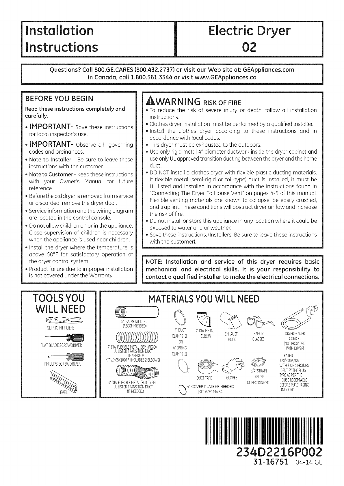
TOOLSYOU
WILL NEED
SLIPJOINTPLIERS
FLATBLADESCREWDRIVER
PHILLIPSSCREWDRIVER
MATERIALSYOUWILL NEED
}
4"DIA,METALDUCT
(RECOMMENDED)
4"DIA,FLEXIBLEMETAL(SEMI-RIGID)
ULLISTEDTRANSITIONDUCT
KITWXOBX!OO77(INCLUDES2ELBOWS)
4"DIA,FLEXIBLEMETAL(FOILTYPE)
(IFNEEDED)
ULLISTEDTRANSITIONDUCT
(IFNEEDED,)
#'DUCT
OR
4"SPRING
CLAMPS(2)
%
4"DIA,METAL
ELBOWCLAMPS(2) EXHAUST
DUCTTAPE GLOVES
HOOD
SAFETY
GLASSES
3/4"STRAIN
RELIEF
ULRECOGNIZED
DRYERPOWER
CORDKIT
(NOTPROVIDED
WITHDRYER)
ULRATED
!20/240V,30A
WITH3OR4PRONGS,
IDENTIFYTHEPLUG
TYPEASPERTHE
HOUSERECEPTACLE
BEFOREPURCHASING
LINECORD,
I,IIIIIIIIIIIIIIIII
234D2216P002
31-16751 0a-la GE
Page 2
Installation instructions
Minimum Clearance Other Than Alcove or Closet Installation
Minimum clearance to combustible surfaces and for air opening are: 0 in.clearance both sides and 1 in. rear.
Consideration must be given to provide adequate clearance for installation and service.
rl] PREPARING FOR INSTALLATION OF
NEW DRYER
TIP:Install your dryer before installing your washer. This
will allow better access when installing dryer exhaust.
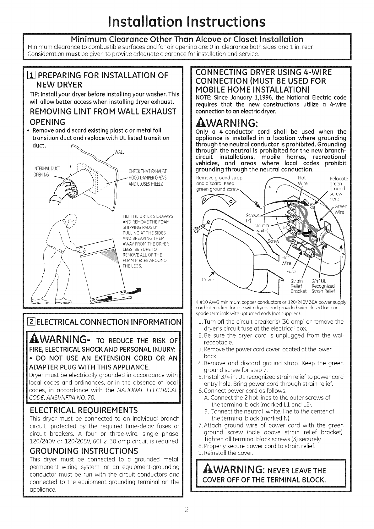
REMOVING LINT FROM WALL EXHAUST
OPENING
• Remove and discard existing plastic or metal foil
transition duct and replace with UL listed transition
duct.
WALL
/
INTERNALDUCT
OPENING DPENS
CHECKTHATEXHAUST
ANDCLOSESFREELY{
TILTTHE DRYER SIDEWAYS
AND REMOVETHE FOAM
SHIPPING PADS BY
PULLING ATTHE SIDES
AND BREAKING THEM
AWAY FROM THE DRYER
LEGS. BESURETO
REMOVEALL OF THE
FOAM PIECESAROUND
THE LEGS.
CONNECTING DRYER USING 4-WIRE
CONNECTION (MUST BE USED FOR
MOBILE HOME INSTALLATION)
NOTE:Since January 1,1996, the National Electric code
requires that the new constructions utilize a 4-wire
connection to an electric dryer.
WARNING:
Only a 4-conductor cord shall be used when the
appliance is installed in a location where grounding
through the neutral conductor is prohibited. Grounding
through the neutral is prohibited for the new branch-
circuit installations, mobile homes, recreational
vehicles, and areas where local codes prohibit
grounding through the neutral conduction.
Remove ground strop Hot Relocate
and discard. Keep Wire green
green ground screw
here
Fuse
Cover
Strain 3/4" UL
Relief Recognized
Bracket Strain Relief
1
[]_]ELECTRICALCONNECTION INFORMATION
,JlVV/-_III'_II'_- TO REDUCE THE RISK OF
FIRE,ELECTRICAL SHOCK AND PERSONAL INJURY:
,,DO NOT USE AN EXTENSION CORD OR AN
ADAPTER PLUG WITH THIS APPLIANCE.
Dryer must be electrically grounded in accordance with
local codes and ordinances, or in the absence of local
codes, in accordance with the NATIONAL ELECTRICAL
CODE,ANSI/NFPANO. 70.
ELECTRICAL REQUIREMENTS
This dryer must be connected to an individual branch
circuit, protected by the required time-delay fuses or
circuit breakers. A four or three-wire, single phase,
!20/240V or 120/208V, 60Hz, 130amp circuit is required.
GROUNDING INSTRUCTIONS
This dryer must be connected to a grounded metal
permanent wiring system, or an equipment-grounding
conductor must be run with the circuit conductors and
connected to the equipment grounding terminal on the
appliance.
4 #10 AWG minimum copper conductors or 120/240V 30A power supply
cord kit marked for use with dryers and provided with closed loop or
spade terminals with upturned ends (not supplied).
!.Turn off the circuit breaker(s)(30 amp) or remove the
dryer's circuit fuse at the electrical box.
2.Be sure the dryer cord is unplugged from the wall
receptacle.
:3.Removethe power cord cover located at the lower
back.
4.Remove and discard ground strap. Keep the green
ground screw for step 7.
5.Install 13/4in.ULrecognized strain relief to power cord
entry hole. Bring power cord through strain relief.
6.Connect power cord as follows:
A. Connect the 2 hot lines to the outer screws of
the terminal block (marked L1 and L2).
B.Connect the neutral (white) lineto the center of
the terminal block (marked N).
7.Attach ground wire of power cord with the green
ground screw (hole above strain relief bracket).
Tighten all terminal block screws (13)securely.
8.Properly secure power cord to strain relief.
9.Reinstall the cover.
,JIW/'_l'IN||'_10: NEVER LEAVE THE
COVER OFF OF THE TERMINAL BLOCK.
Page 3
Installation
Instructions
CONNECTING DRYER USING 3-WIRE
CONNECTION
If required, by local code, install external ground (not provided)
to grounded metal, cold water pipe, or other established ground
determined by a qualified electrician.
f _ Wire
Green Ground Screw
& Ground Strap
Cover
3 #10 AWG minimum copper conductors or 120/240V 30A power supply
cord kit marked for use with dryers and provided with closed loop or
spade terminals with upturned ends (not supplied).
3-wire Connection
Not for use in Canada.
DONOTuse for Mobile Home Installations.
NOTfor use on new construction.
NOTfor use on recreational vehicles.
NOTfor use in areas where local codes prohibit
grounding through the neutral conduction.
!. Turn off the circuit breaker(s) (30 amp) or remove the
dryer's circuit fuse at the electrical box.
2. Besure the dryer cord is unplugged from the wall.
3. Remove the power cord cover located at the lower
back.
4. Install 3/4 in. UL recognized strain relief to power cord
entry hole. Bring power cord through strain relief.
5. Connect power cord as follows:
A. Connect the 2 hot lines to the outer screws of the
terminal block (marked L! and L2).
B.Connect the neutral (white) lineto the center of the
terminal block (marked N).
6. Be sure ground strap is connected to neutral (center)
terminal of block and to green ground screw on
cabinet rear. Tighten all terminal block screws (3)
securely.
7. Properly secure power cord to strain relief.
8. Reinstall the cover.
,_LVM/_I'II_I|I_I_: NEVER LEAVE THE
COVER OFF OF THE TERMINAL BLOCK.
Hot
Fuse
Strain 3/4" UL
Relief Recognized
Bracket Strain Relief
EXHAUST INFORMATION
kWARNING - IN CANADA AND IN THE
UNITED STATES, THE REQUIRED EXHAUST
DUCT DIAMETER IS 4 in (102mm}. DO NOT
USE DUCT LONGER THAN SPECIFIED IN THE
EXHAUST LENGTH TABLE.
Using exhaust longer than specified length will:
, Increase the drying times and the energy cost.
, Reducethe dryer life.
, Accumulate lint, creating a potential fire hazard.
The correct exhaust installation is YOUR
RESPONSIBILITY.Problems due to incorrect
installation are not covered by the warranty.
Remove and discard existing plastic or metal foil
transition duct and replace with UL listed transition
duct.
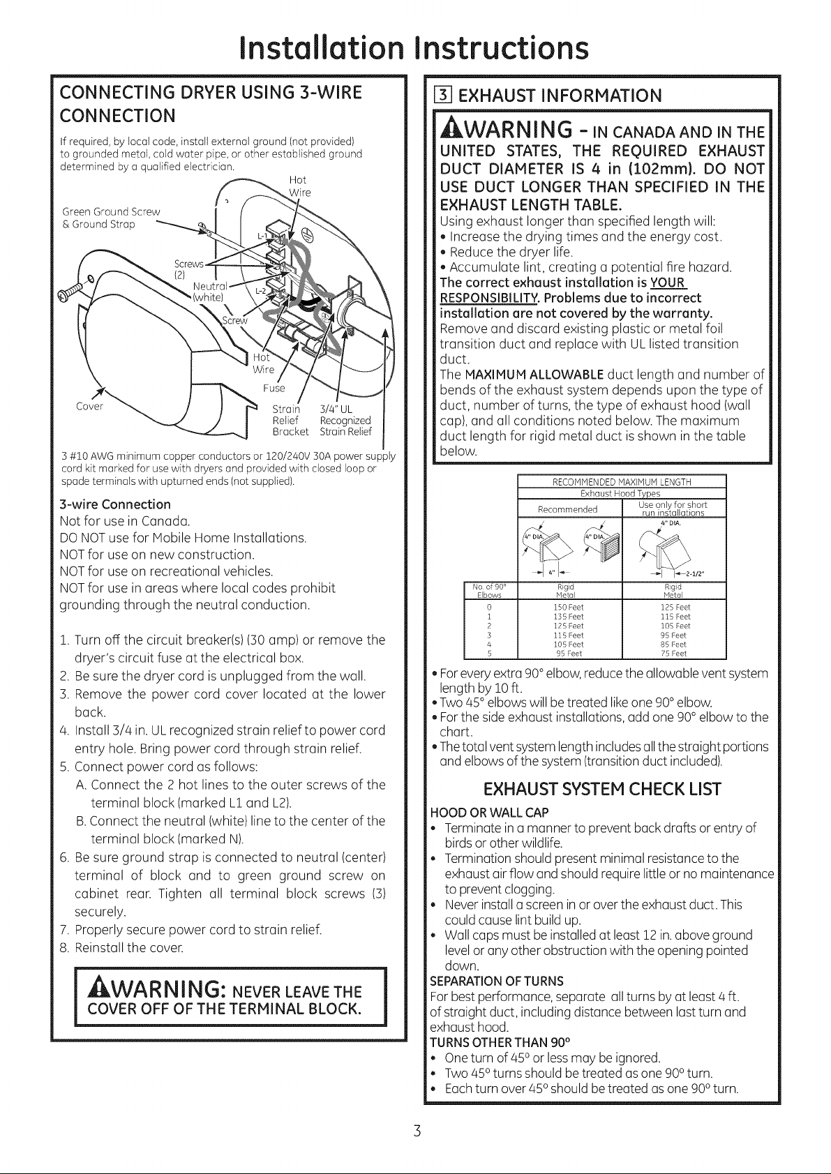
The MAXIMUM ALLOWABLE duct length and number of
bends of the exhaust system depends upon the type of
duct, number of turns, the type of exhaust hood (wall
cap), and all conditions noted below. The maximum
duct length for rigid metal duct isshown in the table
below.
RECOMMENDEDMAXIMUMLENGTH
Exhaust Hood Types
Recommended run installotions
.....4 0,,I.....
No of 90° Rigid Rigid
Elbows Metol Metal
0 150 Feet 125 Feet
i 135 Feet 115 Feet
2 125 Feet 105 Feet
3 115 Feet 95 Feet
4 105 Feet 85 Feet
5 95 Feet 75 Feet
, Foreveryextra 90°elbow,reducethe allowable vent system
length by 10 ft.
, Two 45° elbows will betreated likeone 90° elbow.
, Forthe side exhaust installations, add one 90° elbow to the
chart.
, Thetotal ventsystem lengthincludes allthe straight portions
and elbows ofthe system(transition duct included).
EXHAUST SYSTEM CHECK LIST
HOODORWALLCAP
, Terminate in a manner to prevent backdrafts or entry of
birdsor other wildlife.
, Termination should present minimal resistanceto the
exhaust air flow and should require little or no maintenance
to prevent clogging.
, Never installa screeninor overthe exhaust duct. This
could cause lint build up.
, Wall caps must be installed at least 12 in.above ground
levelor any other obstruction with the opening pointed
down.
SEPARATIONOFTURNS
Forbest performance, separate allturns by at least 4 ft.
of straight duct, including distance between last turn and
exhaust hood.
TURNSOTHERTHAN90°
, One turn of 450or lessmay beignored.
, Two 450turns should betreated asone 900turn.
, Eachturn over 450should be treated as one900turn.
Use only for short
Page 4

Installation Instructions
SEALING OF JOINTS
. All joints should be tight to avoid leaks. The male end of
each section of duct must point away from the dryer.
. The duct shall not be assembled with screws or other
fastening means that extend into the duct and catch
lint.
. Duct joints can be made air and moisture-tight by
wrapping the overlapped joints with duct tape.
. Horizontal runs should slope clown toward the outdoors
1/4 inch per foot.
INSULATION
Duct work that runs through an unheated area or is near air
conditioning should be insulated to reduce condensation
and lint build-up.
[] EXHAUST CONNECTION
WARNING - TO REDUCE THE
RISK OF FIRE OR PERSONAL INJURY:
.This clothes dryer must be exhausted to the outdoors.
. Use only 4" rigid metal ducting for the home exhaust
duct.
.Use only 4" rigid metal or UL-listed flexible metal
(semi-rigid or foil-type) duct to connect the dryer
to the home exhaust duct. It must be installed
in accordance with the instructions found in
"Connecting the Dryer to House Vent" on pages 4-5
of this manual.
.Do not terminate exhaust in a chimney, a well,
a ceiling, gas vent, crawl space, attic, under an
enclosed floor, or in any other concealed space
of a building. The accumulated lint could create a
potential fire hazard.
.Never terminate the exhaust into a common duct
with a kitchen exhaust system. A combination of
grease and lint creates a potential fire hazard.
. Do not use duct longer than specified in the exhaust
length table. Longer ducts can accumulate lint,
creating a potential fire hazard.
. Never install a screen in or over the exhaust duct. This
will cause lint to accumulate, creating a potential fire
hazard.
.Do not assemble ductwork with any fasteners
that extend into the duct. These fasteners can
accumulate lint, creating a potential fire hazard.
. Do not obstruct incoming or exhausted air.
.Provide an access for inspection and cleaning of
the exhaust system, especially at turns and joints.
Exhaust system shall be inspected and cleaned at
least once a year.
THIS DRYER COMES READY FOR REAR
EXHAUSTING. IF SPACE IS LIMITED,
USE THE INSTRUCTIONS IN STEP :1.0TO
EXHAUST DIRECTLY FROM THE SIDE OR
THE BOTTOM OF THE CABINET.
STANDARD REAR EXHAUST
(Vented at floor level)
FOR STRAIGHT LINE INSTALLATION,
CONNECT THE DRYER EXHAUST TO
THE EXTERNAL EXHAUST HOOD
USING DUCT TAPE OR CLAIqR
EXTERNAL
DUCT
OPENING
DUCT TAPE OR
DUCT CLAMP
4" METAL DUCT
(CUT TO PROPER
LENGTH) DUCT TAPE OR
DUCT CLAMP
NOTE: WE STRONGLY RECOMMEND SOLID METAL EXHAUST DUCTING.
HOWEVER, IF FLEXIBLE DUCTING IS USED IT MUST BE UL-LISTED META
NOT PLASTIC.
STANDARD REAR EXHAUST
(Vented above floor level)
ELBOWHIGHLY
_ RECOMMENDED
RECOMMENDED
CONFIGURATION
TOMINIMIZE
EXHAUST
BLOCKAGE.
ELBOWHIGHLY
RECOMMENDED--
NOTE: ELBOWS WILL PREVENT DUCT
KINKING AND COLLAPSING.
CONNECTING THE DRYER TO HOUSE
VENT
RIGID METAL TRANSITION DUCT
. For best drying performance, a rigid metal transition
duct is recommended.
. Rigid metal transition ducts reduce the risk of crushing
and kinking.
UL-LISTED FLEXIBLE METAL (SEMI-RIGID} TRANSITION
DUCT
. If rigid metal duct cannot be used, then UL-listed
flexible metal (semi-rigid) ducting can be used (Kit
WXO8X!O077).
4
Page 5

Installation instructions
. Never install flexible metal duct in walls, ceilings, floors
or other enclosed spaces.
. Total length of flexible metal duct should not exceed 8
feet (2.4m).
. Formany applications, installing elbows at both the dryer
and the wall is highly recommended (see illustrations
below). Elbows allow the dryer to sit close to the wall
without kinking and or crushing the transition duct,
maximizing drying performance.
. Avoid resting the duct on sharp objects.
UL-LISTEDFLEXIBLEMETAL(FOIL-TYPE)TRANSITIONDUCT
. In special installations, it may be necessary to connect
the dryer to the house vent using a flexible metal (foil-
type) duct. A UL-listed flexible metal (foil-type) duct may
be used ONLYin installations where rigid metal or flexible
metal (semi-rigid) ducting cannot be used AND where u
4" diameter can be maintained throughout the entire
length of the transition duct.
. In Canada and the United States,only the flexible metal
(foil-type) ducts that comply with the "Outline for Clothes
Dryer Transition Duct Subject 2158A" shall be used.
. Never install flexible metal duct in walls, ceilings, floors
or other enclosed spaces.
. Total length of flexible metal duct should not exceed 8
feet (2.4m).
. Avoid resting the duct on sharp objects.
For best drying performance
1 Slide one end of the duct over the clothes dryer outlet
pipe.
2.Secure the duct with a clamp.
3.With the dryer inits permanent position, extend the duct
to its full length. Allow 2" of duct to overlap the exhaust
pipe. Cut off and remove excess duct. Keep the duct as
straight as possible for maximum airflow.
4.Secure the duct to the exhaust pipe with the other
clamp.
[] LEVELING AND STABILIZING YOUR DRYER
Stand the dryer upright near the final location and ad-
just the 4 leveling legs, at the corners, to ensure that the
dryer is level from side to side and front to rear.
LEVEL
FRONT-TO-BACK.
LEVEL
SIDE-TO-SIDE
ELBOW HIGHLY
RECOMMENDED
LENGTi
EXHAUST
-'_S HIGHLY
RECOMMENDED
. If your dryer isapproved for installation in an alcove or
closet, it will be stated on a label on the dryer back.
.The dryer MUST be vented to the outdoors. See the
E×HAUSTINFORMATIONsections 3 & 4.
.Minimum clearance between dryer cabinet and
adjacent walls or other surfaces is:
SLTDRYER
ON FLEXLBLE
DO
.Minimum vertical space from floor to overhead
cabinets, ceiling, etc. is 52 in.
. Closet doors must be Iouvered or otherwise ventilated
and must contain a minimum of 60 sq. in.of open area
equally distributed. If the closet contains both a washer
and a dryer, doors must contain a minimum of 120 sq.
in. of open area equally distributed.
4 LEVELINGLEGS
ALCOVE OR CLOSET INSTALLATION
0 in. either side
3 in. front
3 in. rear
Page 6

Installation
Instructions
[-_ BATHROOM OR BEDROOM iNSTALLATION
.The dryerWIUST be ventedtotheoutdoors.See EXHAUST
INFORMATION section3 &4.
. The installation must conform with local codes or, inthe
absence of local codes, with the NATIONAL ELECTRICAL
CODE, ANSI/NFPA NO. 70.
[_ MOBILE OR MANUFACTURED HOME
INSTALLATION
.Installation must conform to the MANUFACTURED
HOME CONSTRUCTION & SAFETY STANDARD, TITLE 24,
PART32-80 or, when such standard is not applicable,
with AMERICAN NATIONAL STANDARD FOR MOBILE
HOME, ANSI/NFPA NO. 501B.
.The dryer MUST be vented to the outdoors with the
termination securely fastened to the mobile home
structure. (See EXHAUST INFORMATION section 3 & 4).
.The vent MUST NOT be terminated beneath a mobile or
manufactured home.
.The vent duct material MUST BE METAL.
. Do not use sheet metal screws or other fastening devices
which extend into the interior of the exhaust vent.
. See section 2 for electrical connection information.
FIXINGHOLE
B A
Cut the duct as shown and keep portion A.
TAB LOCATION
BENDTAB
UP45°
Through the rear opening, locate the tab inthe middle of
the appliance base. Lift the tub to (]bout 45° using (]flat
blade screwdriver.
_7 GARAGE INSTALLATION {IF ALLOWED
BY LOCAL CODES}
. Dryers installed in garages must be elevated !8 inches
(46cm) above the floor.
[rO7DRYER EXHAUST TO RIGHT OR
BOTTOM CABINET
, WARNING- BEFOREPERFORMING
THIS EXHAUST INSTALLATION, BE SURE
TO DISCONNECT THE DRYER FROM iTS
ELECTRICAL SUPPLY. PROTECT YOUR
HANDS AND ARMS FROM SHARP EDGES
WHEN WORKING INSIDE THE CABINET.
BE SURE TO WEAR GLOVES.
REMOVE
SCREW
ANDSAVE.
ADDING NEW DUCT
FIXING
HOLE
PORTIONW'
Reconnect the cut portion (A)of the duct to the blower
housing. Make sure that the shortened duct is aligned with
the tab in the base. Use the screw saved previously to secure
the duct in place through the tab on the appliance base.
REMOVEDESIRED
KNOCKOUT(ONEONLY).
Detach and remove the bottom or right side knockout as
desired. Remove the screw inside the dryer exhaust duct
and save. Pull the duct out of the dryer.
6
Page 7

Installation instructions
ADDING ELBOW AND DUCT FOR
EXHAUST TO RIGHT SIDE OF CABINET
, Preassemble 4" elbow with 4" duct. Wrap duct tape
around joint.
*Insert duct assembly, elbow first, through the side
opening and connect the elbow to the dryer internal
duct.
ACAUTION: BesurenottopuUor damage the
electrical wires inside the dryer when inserting the duct.
DUCT
TAPE
ADDING COVER PLATE TO REAR OF
CABINET (SIDES AND BOTTOM EXHAUST)
q
PLATE'_
(KITWEl1454)
Connect standard metal elbows and ducts to complete
the exhaust system. Cover back opening with a plate (Kit
WEIM/45/4)available from your local service provider. Place
dryer infinal location.
_kWARNING-NEVER LEAVE
THE BACK OPENING WITHOUT THE
PLATE (KIT WEl1454).
, Apply duct tape as shown on the joint between the
dryer internal duct and the elbow.
DUCT
CAUTION:
Internal duct joints must be
secured with tape, otherwise
they may separate and cause
a safety hazard.
hi
ADDING ELBOW FOR EXHAUST
THROUGH BOTTOM OF CABINET
, Insert the elbow through the rear opening and connect
it to the dryer internal duct.
Apply duct tape on the joint between the dryer internal
duct and elbow, as shown above.
_CHANGING DIRECTIONOF DOOROPENING
1.Open the door and remove the filler plugs opposite the
hinges. With the door completely open, remove the
bottom screw from each hinge on the dryer face. Insert
these screws about halfway into the TOP holes, for each
hinge on the opposite side (where you removed the filler
plugs). Apply firm pressure to get the screws started.
REMOVE/4 PLUGS AND KEEP
FOR INSERTION INTO
THE OPPOSITE SIDE
2. Loosenthe top screw from each hinge on the dryer face
half way. With one hand holding the top of the door and
the other hand holding the bottom, remove the door
from the dryer by lifting it UP and OFF.
SCREW HALF WAY AND LIFTTHE
DOOR UP AND OFF
REMOVE BOTTOM SCREW FROM EACH HINGE
AND INSTALL HALF WAY INTO EACH TOP OF
OPPOSITE HINGE HOLES
CAUTION:
Internal duct joints must be secured with tape,
otherwise they may separate and cause a
safety hazard.
oo
Page 8

Installation instructions
Ff_CHANGING DiRECTiONOFDOOR OPENING
(Cont.}
3.Remove the blind plate from the hinge side of the dryer
by removing its two screws. Removethe strike plate from
the opposite side of the dryer by removing its two screws.
Reinstall the plates, on the opposite sides, using two
screws in each plate.
BLIND
PLATE
4. Rotate the door 180o. Insert the door on the opposite
side of the opening by moving the door ON and DOWN
until the top hinge and the bottom hinge are resting on
the top screws inserted in step 1.
//
ROTATE DOOR 180 ° AND HANG
PLATE
r_ SERVICING
,WAR NING- LABELALLWIRESPRIOR
TO DISCONNECTING WHEN SERVICING
CONTROLS, WIRING ERRORS CAN CAUSE
IMPROPER AND DANGEROUS OPERATION
AFTER SERVICING/INSTALLATION.
REGISTER YOUR NEW APPLIANCE TO RECEIVE
ANY IMPORTANT PRODUCT NOTIFICATIONS.
Please go to www.GEAppliences.com or mail in
your product registration card.
Forquestions on installation, cull: 800.626.2000 (US)or
800-561-3344 (Canada).
5.Remove the remaining screws from the side of the
opening from which the door was removed. With these
screws secure each hinge at the bottom. Tighten the
two top screws on each hinge. Reinsert the plastic plugs
on the side from which the door was removed.
INSTALLAND TIGHTEN BOTTOM
SCREWS AND TIGHTEN TOP
INSERT PLUGS
INTO HOLES ON
_LoOPPOSITE SIDE
8
 Loading...