

GE GTD81ESPJ0MC, GTD81ESPJ1MC, GTD81ESSJ0WS, GTD81ESSJ1WS, GTD86ESPJ0MC Installation Guide
...Page 1
Installati
n
Electric ryers
In tructi
i Questions? CaJJ800.GE.CARES {800.432.2737)orvisitour Web siteat:GEAppliances.com i
This isthe safety alert symbol. This symbol alerts you to potential hazards that can kill you or hurt you and others.
A
All safety messages will follow the safety alert symbol and the word "DANGER","WARNING", or "CAUTION".These
words are defined as:
Indicates a hazardoussituation which, if not avoided,will resultin death or seriousinJury.
Indicates a hazardoussituation which, if not avoided, could result indeath or seriousinJury.
Indicates a hazardoussituation which, if not avoided, could result inminor or moderate inJury.
BEFORE YOU BEGIN
Readthese instructions compJeteJyand carefuJly.
• IMPORTANT-Savethese instructions for local
electrical inspector's use.
• IMPORTANT- Observe all governing codes and
ordinances.
• Installthe clothes dryer according to the manufacturer's
instructions and local codes.
• Note to Installer - Be sure to leavethese instructions
with the Consumer.
• Note to Consumer - Keepthese instructions for future
reference.
• Clothes dryer installation must be performed by a
qualified installer.
• Thisdryer must be exhausted to the outdoors.
• Before the old dryer is removed from service or
discarded, remove the dryer door.
• Service information and the wiring diagram are located
in the control console.
• Do not allow children on or in the appliance. Close
supervision of children isnecessary when the appliance
is used near children.
• Proper installation isthe responsibility of the installer.
• Product failure due to improper installation is not
covered under the Warranty.
• Install the dryer where the temperature is above 50°F
for satisfactory operation of the dryer control system.
• Remove and discard existing plastic or metal foil duct
and replace with U/_-Iistedduct.
ns
- Fire Hazard
• Clothes dryer installation must be performed by a
qualified installer.
• Install the clothes dryer according to these
instructions and local codes.
• DO NOT install a clothes dryer with flexible plastic
venting materials. If flexible metal (semi-rigid or
foil-type) duct is installed, it must be UL-listed and
installed in accordance with the instructions found
in "Connecting the Dryer to House Vent" later in
this manual. Flexible vent materials are known to
collapse, be easily crushed and trap lint. These
conditions will obstruct dryer airflow and increase
the risk of fire.
• DO NOT install or store this appliance in any
location where it could be exposed to water or
weather.
• To reduce the risk of severe inJuryor death, follow
all installation instructions.
Save these instructions. (Installers: Be sure to leave
these instructions with the customer.)
01
Printed in Mexico
II1II1111111111111111111IIIIIIIIIIIIIII
234D1753P005
31-16761 o2-1s GE
Page 2
Installation Instructions
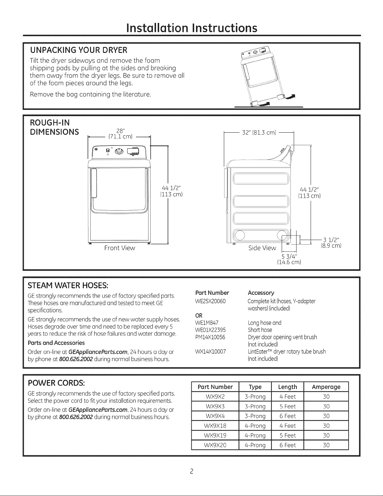
UNPACKING YOUR DRYER
Tilt the dryer sideways and remove the foam
shipping pads by pulling at the sides and breaking
them away from the dryer legs. Be sure to remove all
of the foam pieces around the legs.
Remove the bag containing the literature.
ROUGH-IN
DIMENSIONS
28"
(71.1cm)
32" (81.3 cm) j.
4a1/2"
(113cm)
Front View
STEAM WATER HOSES:
GEstrongly recommends the useof factory specifiedparts.
Thesehosesare manufactured andtested to meet GE
specifications.
GEstrongly recommends the useof new water supply hoses.
Hosesdegrade overtime and need to be replaced every 5
years to reducethe risk of hose failures and water damage.
Parts and Accessories
Order on-line at GEApplioncePorts.com, 24 hours a day or
by phone at 800.626.2002during normal businesshours.
Pert Number
WE25X20060
OR
WE1H847
WE01X22395
PH14X10056
WX14X10007
(
Side View
S 314"
(14.6 cm)
Accessory
Completekit(hoses,Y-adapter
washers)(included)
Longhoseand
Shorthose
Dryerdooropeningventbrush
(notincluded)
LintEaterTM dryerrotarytubebrush
(notincluded)
4a1/2"
(113cm)
-- 3 1/2"
(8.9cm)
POWER CORDS:
GEstrongly recommends the useof factory specifiedparts.
Selectthe power cord to fityour installation requirements.
Order on-line at GEApplionceParts.com, 24 hours a day or
by phone at 800.626.2002during normal businesshours.
Part Number Type Length Amperage
WX9X2 3-Prong 4 Feet 30
WX9X3 3-Prong 5 Feet 30
WX9X4 3-Prong 6 Feet 30
WX9X18 4-Prong 4 Feet 30
WX9X19 _ 4-Prong • 5 Feet . 30
WX9X20 4-Prong 6 Feet 30
Page 3
Installation Instructions
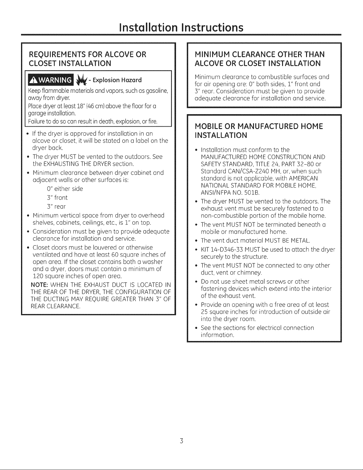
REQUIREMENTS FOR ALCOVE OR
CLOSET INSTALLATION
_- Explosion Hazard
Keepflammable materials and vapors, such as gasoline,
away from dryer.
Placedryer at least 18" (46 cm) above the floor for a
garage installation.
Failureto do so can result in death, explosion, or fire.
, If the dryer is approved for installation in an
alcove or closet, it will be stated on a label on the
dryer back.
, The dryer MUST be vented to the outdoors. See
the EXHAUSTING THE DRYER section.
, Minimum clearance between dryer cabinet and
adjacent walls or other surfaces is:
O" either side
3" front
3" rear
. Minimum vertical space from dryer to overhead
shelves, cabinets, ceilings, etc., is 1" on top.
. Consideration must be given to provide adequate
clearance for installation and service.
Closet doors must be Iouvered or otherwise
ventilated and have at least 60 square inches of
open area. If the closet contains both a washer
and a dryer, doors must contain a minimum of
120 square inches of open area.
NOTE: WHEN THE EXHAUST DUCT IS LOCATED IN
THE REAR OF THE DRYER,THE CONFIGURATION OF
THE DUCTING MAY REQUIRE GREATER THAN 3" OF
REARCLEARANCE.
MINIMUM CLEARANCE OTHER THAN
ALCOVE OR CLOSET INSTALLATION
Minimum clearance to combustible surfaces and
for air opening are: O" both sides, 1" front and
3" rear. Consideration must be given to provide
adequate clearance for installation and service.
MOBILE OR MANUFACTURED HOME
INSTALLATION
, Installation must conform to the
MANUFACTURED HOME CONSTRUCTION AND
SAFETYSTANDARD, TITLE 24, PART32-80 or
Standard CAN/CSA-Z240 MH, or, when such
standard is not applicable, with AMERICAN
NATIONAL STANDARD FOR MOBILE HOME,
ANSI/NFPA NO. 502B.
, The dryer MUST be vented to the outdoors. The
exhaust vent must be securely fastened to a
non-combustible portion of the mobile home.
, The vent MUST NOT be terminated beneath a
mobile or manufactured home.
, The vent duct material MUST BE METAL.
, KIT 14-D346-33 MUST be used to attach the dryer
securely to the structure.
, The vent MUST NOT be connected to any other
duct, vent or chimney.
, Do not use sheet metal screws or other
fastening devices which extend into the interior
of the exhaust vent.
, Provide an opening with a free area of at least
25 square inches for introduction of outside air
into the dryer room.
, See the sections for electrical connection
information.
Page 4
Installation Instructions
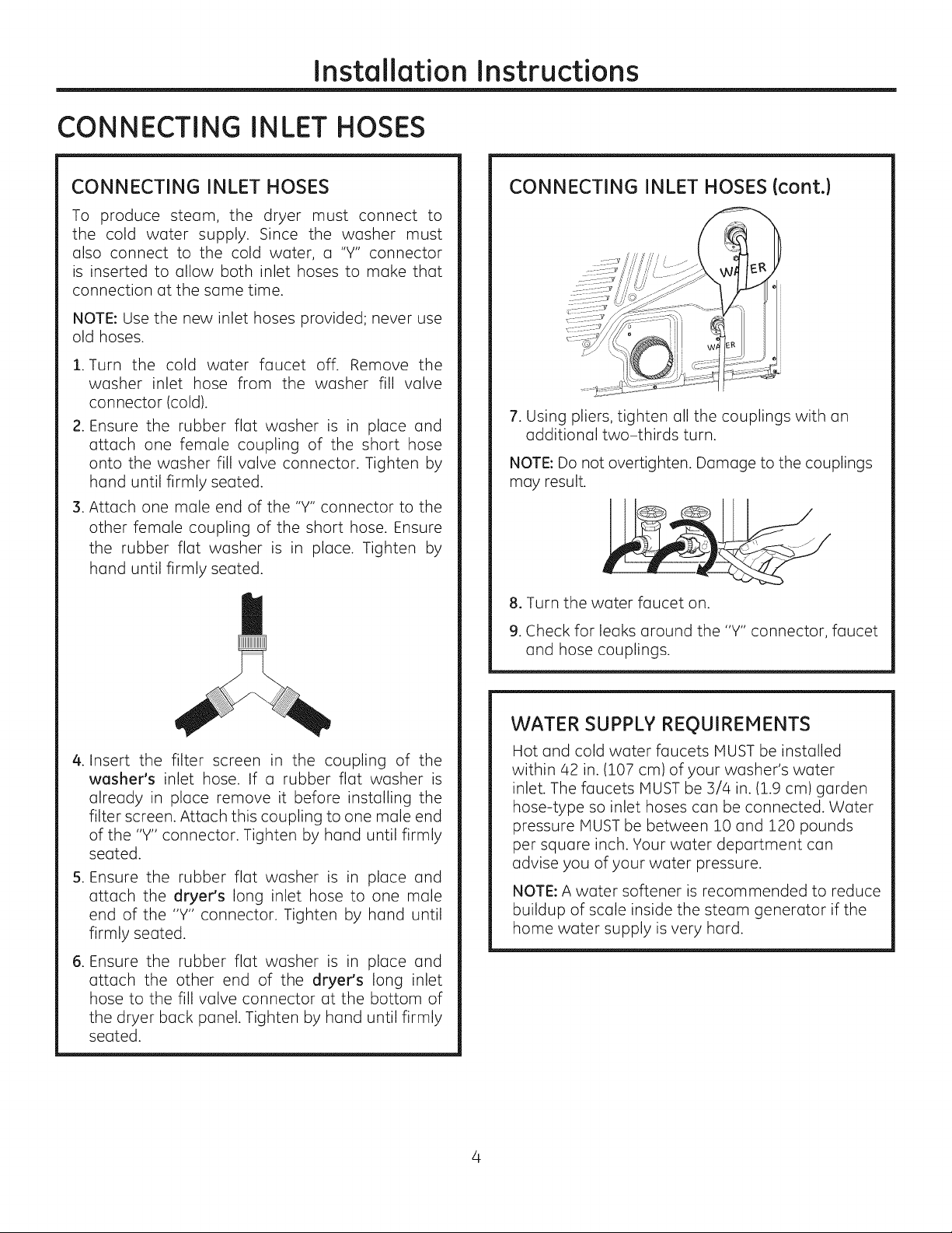
CONNECTING INLET HOSES
CONNECTING INLET HOSES
To produce steam, the dryer must connect to
the cold water supply. Since the washer must
also connect to the cold water, a "Y" connector
is inserted to allow both inlet hoses to make that
connection at the same time.
NOTE: Use the new inlet hoses provided; never use
old hoses.
.
Turn the cold water faucet off. Remove the
washer inlet hose from the washer fill valve
connector (cold).
.
Ensure the rubber flat washer is in place and
attach one female coupling of the short hose
onto the washer fill valve connector. Tighten by
hand until firmly seated.
.
Attach one male end of the "Y" connector to the
other female coupling of the short hose. Ensure
the rubber flat washer is in place. Tighten by
hand until firmly seated.
CONNECTING INLET HOSES (cont.)
7. Using pliers, tighten all the couplings with an
additional two-thirds turn.
NOTE: Do not overtighten. Damage to the couplings
may result.
8. Turn the water faucet on.
9. Check for leaks around the "Y" connector, faucet
and hose couplings.
.
Insert the filter screen in the coupling of the
washer's inlet hose. If a rubber flat washer is
already in place remove it before installing the
filter screen. Attach this coupling to one male end
of the "Y" connector. Tighten by hand until firmly
seated.
S.
Ensure the rubber flat washer is in
attach the dryer's long inlet hose to
end of the "Y" connector. Tighten by
place and
one male
hand until
firmly seated.
. Ensure the rubber flat washer is in
attach the other end of the dryer's
hose to the fill valve connector at the
the dryer back panel. Tighten by hand
place and
long inlet
bottom of
until firmly
seated.
WATER SUPPLY REgUIREMENTS
Hot and cold water faucets MUST be installed
within 42 in. (107 cm) of your washer's water
inlet. The faucets MUST be 3/4 in. (1.9 cm) garden
hose-type so inlet hoses can be connected. Water
pressure MUST be between 10 and 120 pounds
per square inch. Your water department can
advise you of your water pressure.
NOTE: A water softener is recommended to reduce
buildup of scale inside the steam generator if the
home water supply is very hard.
Page 5
Installation Instructions
CONNECTING AN ELECTRIC DRYER
(Skip if your dryer already has a power cord attached)
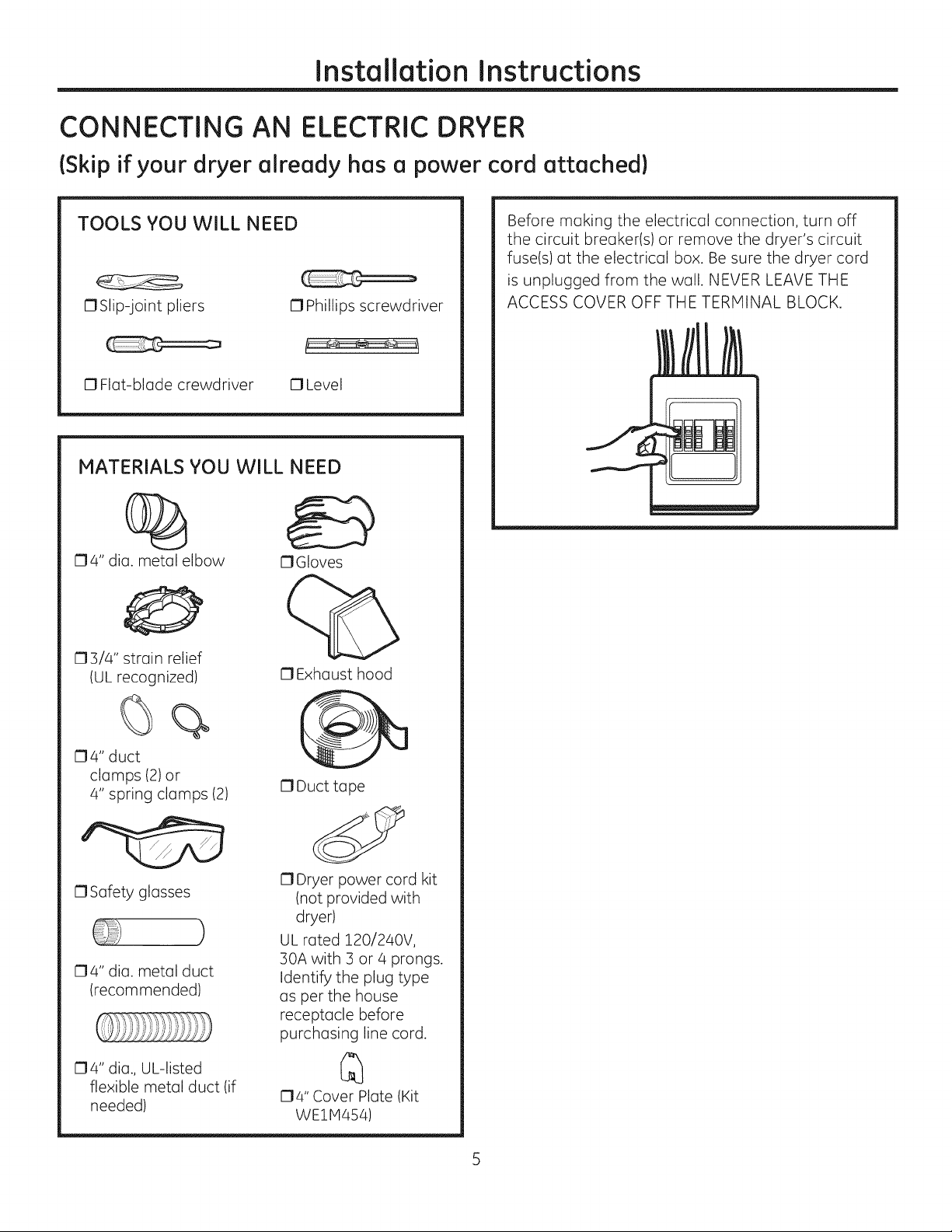
TOOLS YOU WiLL NEED
OSlip-joint pliers O Phillips screwdriver
0 Flat-blade crewdriver 0 Level
MATERIALS YOU WILL NEED
O4" dia. metal elbow
O3/4" strain relief
(UL recognized)
OGIoves
O Exhaust hood
Before making the electrical connection, turn off
the circuit breaker(s) or remove the dryer's circuit
fuse(s) at the electrical box. Be sure the dryer cord
is unplugged from the wall. NEVER LEAVE THE
ACCESS COVER OFF THE TERMINAL BLOCK.
04" duct
clamps (2) or
4" spring clamps (2)
0 Safety glasses
04" dia. metal duct
(recommended)
O4" dia., UL-listed
flexible metal duct (if
needed)
0 Duct tape
O Dryer power cord kit
(not provided with
dryer)
)
UL rated 120/240V,
30A with 3 or 4 prongs.
Identify the plug type
as per the house
receptacle before
purchasing line cord.
O4" Cover Plate (Kit
WE1H454)
Page 6
Installation Instructions
CONNECTING AN
ELECTRICDRYER{cont.}
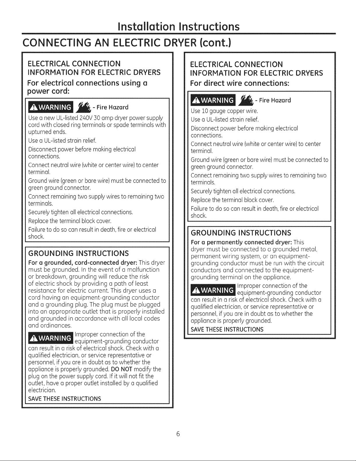
ELECTRICAL CONNECTION
INFORMATION FOR ELECTRIC DRYERS
For electrical connections using a
power cord:
- Fire Hazard
Use a new UL-listed 240V 30 amp dryer power supply
cord with closed ring terminals or spade terminals with
upturned ends.
Use a UL-listed strain relief.
Disconnect power before making electrical
connections.
Connect neutral wire (white or center wire) to center
terminal.
Ground wire (green or bare wire) must be connected to
green ground connector.
Connect remaining two supply wires to remaining two
terminals.
Securely tighten all electrical connections.
Replace the terminal block cover.
Failure to do so can result in death, fire or electrical
shock.
GROUNDING INSTRUCTIONS
For a grounded, cord-connected dryer: This dryer
must be grounded. In the event of a malfunction
or breakdown, grounding will reduce the risk
of electric shock by providing a path of least
resistance for electric current. This dryer uses a
cord having an equipment-grounding conductor
and a grounding plug. The plug must be plugged
into an appropriate outlet that is properly installed
and grounded in accordance with all local codes
and ordinances.
Improper connection of the
equipment-grounding conductor
can result in a risk of electrical shock. Check with a
qualified electrician, or service representative or
personnel, if you are in doubt as to whether the
appliance is properly grounded. DO NOT modify the
plug on the power supply cord. If it will not fit the
outlet, have a proper outlet installed by a qualified
electrician.
SAVE THESE INSTRUCTIONS
ELECTRICAL CONNECTION
INFORMATION FOR ELECTRIC DRYERS
For direct wire connections:
- Fire Hazard
Use 10 gauge copper wire.
Use a UL-listed strain relief.
Disconnect power before making electrical
connections.
Connect neutral wire (white or center wire) to center
terminal.
Ground wire (green or bare wire) must be connected to
green ground connector.
Connect remaining two supply wires to remaining two
terminals.
Securely tighten all electrical connections.
Replace the terminal block cover.
Failure to do so can result in death, fire or electrical
shock.
GROUNDING INSTRUCTIONS
For a permanently connected dryer: This
dryer must be connected to a grounded metal,
permanent wiring system, or an equipment-
grounding conductor must be run with the circuit
conductors and connected to the equipment-
grounding terminal on the appliance.
Improper connection of the
equipment-grounding conductor
can result in a risk of electrical shock. Check with a
qualified electrician, or service representative or
personnel, if you are in doubt as to whether the
appliance is properly grounded.
SAVETHESEINSTRUCTIONS
Page 7
Installation Instructions
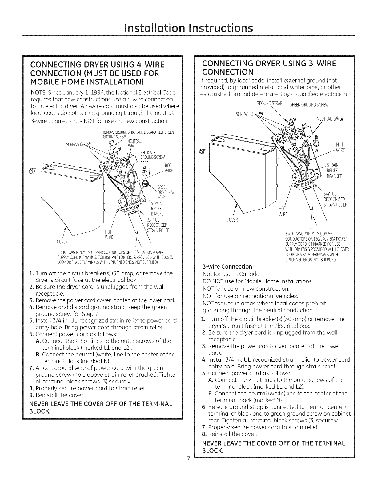
CONNECTING DRYER USING 4-WIRE
CONNECTION (MUST BE USED FOR
MOBILE HOME INSTALLATION)
NOTE:Since January !, 1996,the National Electrical Code
requires that new constructions use a 4-wire connection
to an electric dryer. A 4-wire cord must also be used where
local codes do not permit grounding through the neutral.
3-wire connection is NOTfor use on new construction.
REMOVEGROUNDSTRAPAND DISCARD.KEEPGREEN
GROUNDSCREW
hite)
SCREWS(3),_
COVER
4#1OAWGMINIMUMCOPPERCONDUCTORSOR120/240V30APOWER
SUPPLYCORDKITMARKEDFORUSEWFH DRYERS& PROVIDEDWITHCLOSED
LOOPORSPADETERMINALSWITHUPTURNEDENDS(NOTSUPPLIED[
_ ' NEUTRAL
_ HERE
i GREEN
HOT
WIRE
1. Turn off the circuit breaker(s) (30 amp) or remove the
dryer's circuit fuse at the electrical box.
2. Be sure the dryer cord is unplugged from the wall
receptacle.
3. Removethe power cord cover located at the lower back.
4. Remove and discard ground strap. Keep the green
ground screw for Step 7.
5. Install 3/4 in. UL-recognized strain relief to power cord
entry hole. Bring power cord through strain relief.
6. Connect power cord as follows:
A. Connect the 2 hot lines to the outer screws of the
terminal block (marked L1and L2).
B.Connect the neutral (white) line to the center of the
terminal block (marked N).
7. Attach ground wire of power cord with the green
ground screw (hole above strain relief bracket). Tighten
all terminal block screws (3)securely.
8. Properly secure power cord to strain relief.
9. Reinstall the cover.
NEVER LEAVE THE COVER OFF OF THE TERMINAL
BLOCK.
RELOCATE
GROUNDSCREW
WIRE
RELIEF
BRACKET
RECOGNIZED
STRAINRELIEF
HOT
CONNECTING DRYER USING 3-WIRE
CONNECTION
If required, by local code, install external ground (not
provided) to grounded metal, cold water pipe, or other
established ground determined by a qualified electrician.
GROUNDSTRAP GREENGROUNDSCREW
x
SCREWS(])
HOT
WIRE
COVER
B#i0AWG MINIMUMCOPPER
CONDUCTORSOR120/240V30APOWER
SUPPLYCORDKITMARKEDFORUSE
WFH DRYERS&PROVIDEDWITHCLOSED
LOOPORSPADETERMINALSWITH
UPTURNEDENDS(NOTSUPPLIED),
3-wire Connection
Not for usein Canada.
DO NOTuse for Mobile Home Installations.
NOTfor use on new construction.
NOTfor use on recreational vehicles.
NOTfor use in areas where local codes prohibit
grounding through the neutral conduction.
1. Turn off the circuit breaker(s) (30 amp) or remove the
dryer's circuit fuse at the electrical box.
2. Be sure the dryer cord is unplugged from the wall
receptacle.
3. Remove the power cord cover located at the lower
back.
4. Install 3/4-in. UL-recognized strain relief to power cord
entry hole. Bring power cord through strain relief.
5. Connect power cord as follows:
A. Connect the 2 hot lines to the outer screws of the
terminal block (marked L! and L2).
B. Connect the neutral (white) line to the center of the
terminal block (marked N).
6. Be sure ground strap is connected to neutral (center)
terminal of block and to green ground screw on cabinet
rear. Tighten all terminal block screws (3)securely.
7. Properly secure power cord to strain relief.
8. Reinstall the cover.
NEVER LEAVE THE COVER OFF OF THE TERMINAL
BLOCK.
NEUTRAL(White)
(_ HOT
RELIEF
BRACKET
RECOGNIZED
STRAINRELIEF
Page 8
Installation Instructions
EXHAUSTING THE DRYER
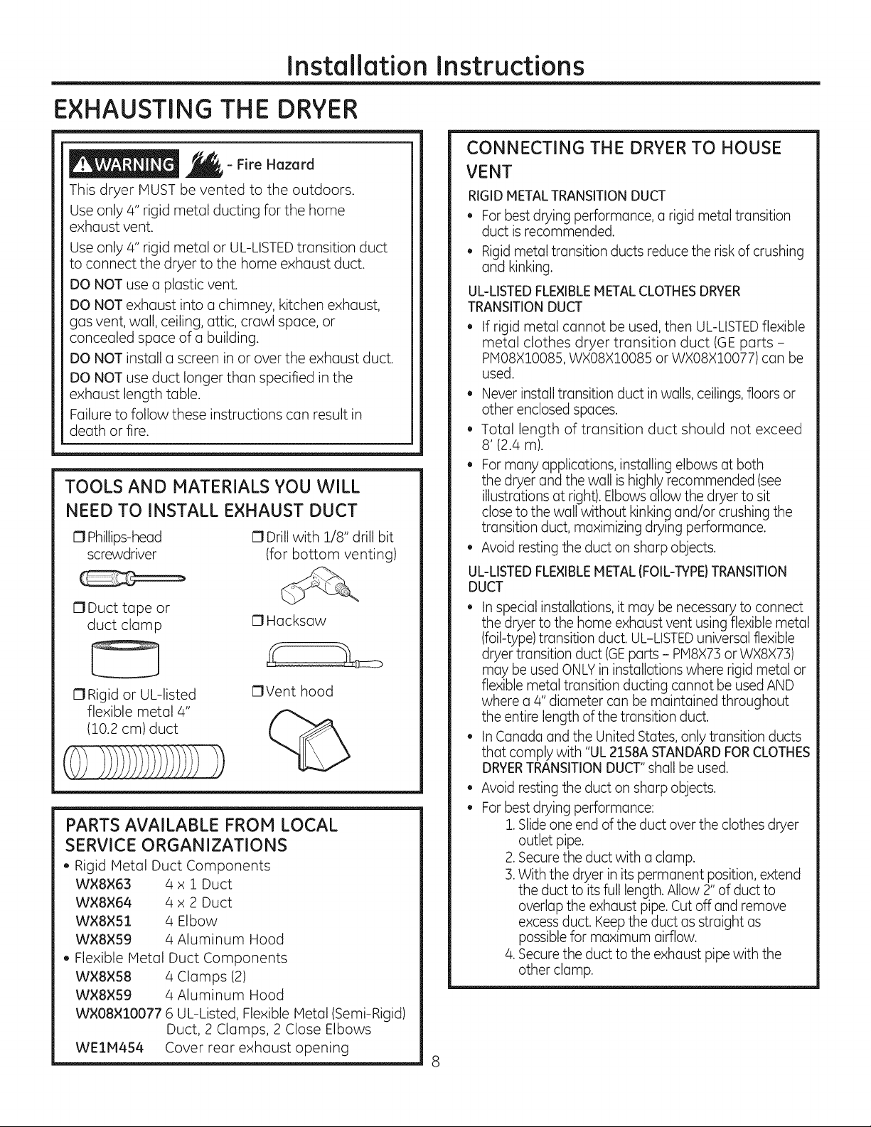
- Fire Hazard
This dryer MUST be vented to the outdoors.
Use only 4" rigid metal ducting for the home
exhaust vent.
Use only 4" rigid metal or UL-LISTEDtransition duct
to connect the dryer to the home exhaust duct.
DO NOT use a plastic vent.
DO NOT exhaust into a chimney, kitchen exhaust,
gas vent, wall, ceiling, attic, crawl space, or
concealed space of a building.
DO NOT install a screen in or over the exhaust duct.
DO NOT use duct longer than specified in the
exhaust length table.
Failure to follow these instructions can result in
death or fire.
TOOLS AND MATERIALS YOU WILL
NEED TO INSTALL EXHAUST DUCT
IZ1Phillips-head
screwdriver
17Duct tape or
duct clamp
0 Rigid or UL-listed
flexible metal 4"
(10.2 cm) duct
PARTS AVAILABLE FROM LOCAL
SERVICE ORGANIZATIONS
. Rigid Metal Duct Components
WX8×63 4 x I Duct
W×8×64 4 x 2 Duct
W×8×51 4 Elbow
WX8×S9 4 Aluminum Hood
, Flexible Metal Duct Components
W×8×58 4 Clamps (2)
W×8XS9 4 Aluminum Hood
W×08×10077 6 UL-Listed, Flexible Metal (Semi-Rigid)
Duct, 2 Clamps, 2 Close Elbows
WE1M4S4 Cover rear exhaust opening
0 Drill with 1/8" drill bit
(for bottom venting)
IZ1Hacksaw
17Vent hood
CONNECTING THE DRYER TO HOUSE
VENT
RIGID HETAL TRANSITIONDUCT
• Forbest drying performance, a rigid metal transition
duct isrecommended.
• Rigidmetal transition ducts reduce the risk of crushing
and kinking.
UL-LISTEDFLEXIBLEMETAL CLOTHESDRYER
TRANSITIONDUCT
If rigid metal cannot be used, then UL-LISTEDflexible
metal clothes dryer transition duct (GE parts -
PMO8XlO085, WXO8XlO085 or WXO8XlO077) can be
used.
• Never install transition duct in walls, ceilings,floors or
other enclosed spaces.
• Total length of transition duct should not exceed
8' (2.4 m).
• Formany applications, installing elbows at both
the dryer and the wall is highly recommended (see
illustrations at right). Elbows allow the dryer to sit
close to the wall without kinking and/or crushing the
transition duct, maximizing drying performance.
Avoid resting the duct on sharp objects.
UL-LISTEDFLEXIBLEMETAL (FOIL-TYPE)TRANSITION
DUCT
• Inspecial installations, it may be necessary to connect
the dryer to the home exhaust vent using flexible metal
(foil-type) transition duct. UL-LISTEDuniWrsal flexible
dryer transition duct (GEparts - PM8X7] or WX8X7])
may be used ONLYin installations where rigid metal or
flexible metal transition ducting cannot be used AND
where a/4" diameter can be maintained throughout
the entire length of the transition duct.
InCanada and the United States, only transition ducts
that comply with "UL2158A STANDARDFORCLOTHES
DRYERTRANSITION DUCT"shall be used.
• Avoid resting the duct on sharp objects.
• Forbest drying performance:
1.Slide one end of the duct over the clothes dryer
outlet pipe.
2.Secure the duct with aclamp.
]. With the dryer in its permanent position, extend
the duct to its full length. Allow 2" of duct to
overlap the exhaust pipe. Cut off and remove
excess duct. Keep the duct as straight as
possible for maximum airflow.
/4.Secure the duct to the exhaust pipe with the
other clamp.
Page 9
Installation Instructions
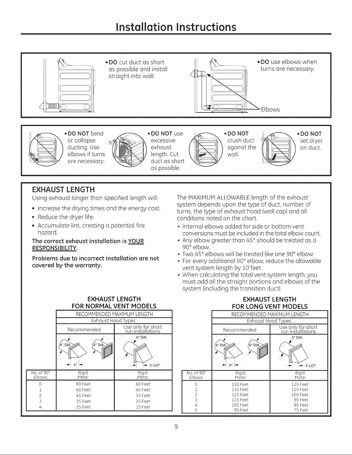
,DO cut duct as short
as possible and install
straight into wall.
(
• DONOTbend _->_ ,DONOTuse
ducting. Use exhaust
elbows if turns length. Cut
or collapse _ excessive
are necessary, duct as short
as possible.
EXHAUST LENGTH
Using exhaust longer than specified length will:
, Increase the drying times and the energy cost.
, Reduce the dryer life.
, Accumulate lint, creating a potential fire
hazard.
The correct exhaust installation is YOUR
RESPONSIBILITY.
Problems due to incorrect installation are not
covered by the warranty.
EXHAUST LENGTH
FOR NORMAL VENT MODELS
RECOMMENDEDMAXIMUMLENGTH
Exhaust Hood Types
Recommended
Use only for short
run installations
4" DIA.
,DO use elbows when
turns are necessary.
_ Elbows
• DO NOT _,DO NOT
crush duct _lx_" set dryer
against the _%_ I on duct.
wall.
The HAXIHUH ALLOWABLE length of the exhaust
system depends upon the type of duct, number of
turns, the type of exhaust hood (wall cap) and all
conditions noted on the chart.
, Internal elbows added for side or bottom vent
conversions must be included in the total elbow count.
, Any elbow greater than 45 ° should be treated as a
90 ° elbow.
, Two 45° elbows will be treated like one 90° elbow.
, For every additional 90 ° elbow, reduce the allowable
vent system length by 10 feet.
, When calculating the total vent system length, you
must add all the straight portions and elbows of the
system (including the transition duct).
EXHAUST LENGTH
FOR LONG VENT MODELS
RECOMMENDEDMAXIMUM LENGTH
Exhaust HoodTypes
Recommended run installations
Use only for short
I
I
No. of 90° Rigid Rigid
Elbows Metal Metal
0 90 Feet 60 Feet
1 60 Feet 45 Feet
2 45 Feet 55 Feet
5 55 Feet 25 Feet
4 25 Feet 15 Feet
1_2-1/2"
No.of 90°
Elbows
0
1
2
5
4
5
Rigid
Metal
150 Feet
15S Feet
125 Feet
115 Feet
105 Feet
95 Feet
4" DIA.
I_ 2-1/2"
Rigid
Metal
125 Feet
115 Feet
105 Feet
95 Feet
85 Feet
75 Feet
Page 10

Installation Instructions
EXHAUSTING THE DRYER(cont.)
EXHAUST SYSTEM CHECKLIST
HOOD ORWALL CAP
• Terminate ina manner to prevent back drafts or entry
of birds or other wildlife.
Termination should present minimal resistance to
the exhaust airflow and should require little or no
maintenance to prevent clogging.
Wall caps must be installed at least 12" above ground
level or any other obstruction with the opening
pointed down.
SEPARATIONOFTURNS
• For best performance, separate all turns by at least
4 ft. of straight duct, including distance between last
turn and dampened wall cap.
SEALINGOFJOINTS
• Alljoints should be tight to avoid leaks.The male end
of each section of duct must point away from the
dryer.
• Duct joints should be made air- and moisture-tight
by wrapping the overlapped joints with duct tape or
aluminum tape.
Do not assemble ductwork with any fasteners
that extend into the duct. These fasteners can
accumulate lint, creating a potential fire hazard.
Horizontal runs should slope down towards the
outdoors 1/4" per foot.
Providean accessfor inspection and cleaning of
the exhaust system,especially at turns and joints.
Exhaustsystem shall be inspected and cleaned at
least once ayear.
INSULATION
• Ductwork that runs through an unheated area or is
near air conditioning should be insulated to reduce
condensation and lint buildup.
BEFORE YOU BEGIN
STANDARD REAR EXHAUST
We recommend that you install your dryer before
installing your washer. This will permit direct
access for easier exhaust connection.
Slide the end of the exhaust duct on the back of the
dryer and secure with duct tape or a duct clamp.
EXTERNAL DUCT
OPENING
DUCT TAPE OR
DUCT CLAMP
4" METAL DUCT CUT
TO PROPER LENGTH
DUCT TAPE OR
DUCT CLAMP
NOTE: We strongly recommend using rigid metal
exhaust duct. However, if flexible ducting is used it
must be UL-Listed metal, not plastic.
, For straight-line installation, connect the dryer
exhaust to the wall, using duct tape or a duct
clamp.
RECOMMENDED CONFIGURATION TO
MINIMIZE EXHAUST BLOCKAGE
Using duct elbows will prevent duct kinking and
collapsing.
, Remove and discard existing plastic or metal foil
duct and replace with UL-listed duct.
, Remove any lint from the wall exhaust opening.
Wall
Internal
Duct
Check that exhaust
hood damper opens
and closes freely.
Transition
Ducting
(
10
Page 11

Installation Instructions
SIDE OR BOTTOM VENTING
- Fire Hazard
Close the back opening with cover plate (Kit
WE1M454).
Disconnect dryer from electrical supply.
Wear gloves and arm guards.
Failure to do so may result in fire, electrical shock
or lacerations.
Remove
screw Ri
and save
......J Left*
Bottom
Remove desired
knockout (one only)
Detach and remove the right, left or bottom
knockout as desired. Remove the screw inside the
dryer exhaust duct and save. Pull the duct out of
the dryer.
*Left side exhaust is not available for Long Vent
models.
Fixing hole
F ..................
', A
L.................... I
,,
I-- !4"(ss.s6cm)--I
TAB LOCATION
.- - _ _ /
Bend tab '_/_ "
Through the rear opening, locate the tab in the
middle of the appliance base. Lift the tab to about
45°,using a flat-blade screwdriver.
ADDING A NEW DUCT
Fixing Portion "A"
Reconnect the cut portion (A)of the duct to the
blower housing. Make sure that the shortened
duct is aligned with the tab in the base. Use the
screw saved previously to secure the duct in place
through the tab on the appliance base.
ADDING ELBOW AND DUCT FOR EXHAUST TO
LEFT OR RIGHT SIDE OF CABINET
/
Cut the duct as shown and keep portion A.
. Preassemble 4" elbow with 4" duct. Wrap duct
tape around joint.
. Insert duct assembly, elbow first, through the
side opening and connect the elbow to the dryer
internal duct.
Be sure not to pull or damage the electrical wires
inside the dryer when inserting the duct.
11
Page 12

Installation
Instructions
EXHAUSTINGTHE
DRYER{cont.}
SIDE OR BOTTOM VENTING (cant,}
ADDING ELBOW AND DUCT FOR EXHAUST TO
LEFT OR RIGHT SIDE OF CABINET {cont.}
, Apply duct tape as
shown on thejoint
between the dryer
internal duct and the
elbow, and also the joint
between the elbow and
the side duct.
Use 4" rigid metal ducting only inside the dryer.
Internal duct joints must be secured with tape,
otherwise they may separate and cause a safety
hazard.
ADDING ELBOW FOR EXHAUST THROUGH
BOTTOH OF CABINET
, Insert the elbow through the rear opening and
connect it to the dryer internal duct.
, Apply duct tape as Duct t(]pe
shown on the joint
between the dryer
internal duct and the
elbow, and also the
joint between the
elbow and the bottom
duct.
Internal duct joints must be secured with tape;
otherwise, they may separate and cause a safety
hazard.
DUCT
TAPE
FINAL SETUP
[] LEVEL THE DRYER
Stand the dryer upright near the final location and
adjust the four leveling legs at the corners to ensure
that the dryer is level from side to side and front to
rear.
Raise Lower
[2"1PLUG DRYER IN
Ensure proper
ground exists
before use.
ADDING COVER PLATE TO REAR OF CABINET
:,"') _J
Plate __
(Kit WE1M454)
Connect standard metal elbows and ducts to
complete the exhaust system. Cover back opening
with a plate (Kit WE1P1454) available from your
local service provider. Place dryer in final location.
NEVER LEAVE THE BACK OPENING WITHOUT THE
PLATE. (Kit WEl1454.)
[_] DRYER START-UP
Press the Power button.
Power
1ol
NOTE: If the dryer has been exposed to
temperatures below freezing for an extended
period of time, allow it to warm up before pressing
Power. Otherwise, the display will not come on.
The dryer is now ready for use.
12
Page 13

Installation Instructions
REVERSINGTHE DOOR
ABOUT REVERSING THE DOOR
IMPORTANT NOTES:
, Read the instructions all the way through before
starting.
, Handle parts carefully to avoid scratching paint.
, Set screws down by their related parts to avoid
using them in the wrong places.
, Provide a non-scratch work surface for the door.
, Normal completion time to reverse the door
swing is 30-60 minutes.
IMPORTANT:
Once you begin, do not move the cabinet until door
swing reversal is completed. These instructions are
for changing the hinges from the right side to the left
side - if you ever want to switch them back to the
right side, follow these same instructions and reverse
all references to the left and right.
Tools needed:
[] Standard #2 Phillips screwdriver
[] Tape-tipped putty knife
[] Small flat blade screwdriver
F1 Remove the bottom screw from each hinge (right
side) and partially insert them into the top left side
hinge holes.
NOTE:All/4 front panel hinge screws will now be in
the top hinge holes- 2 on the left and 2 on the right.
r_ Loosen the bottom 2 right side hinge screws. Remove
the door and place it on a protective flat surface to
avoid any damage. Remove both the blind plate and
the strike plate and install them in opposite positions.
Unplug the dryer from its
electrical outlet
e,o e ou to t
r_ open the door approximately 170 degrees. With a
putty knife, remove the 4 plastic caps located along
the left side of the front panel and set them aside.
Plastic Cap (4)
eo tn#en°I
r_ Remove the 4 door hinge screws, 4 edge screws, and
8 inside screws. Lift the inner door upwards using a
flat blade screwdriver.
Inside screws
Door hinge Inside
screws
Strike
plate
Edge
screws
screws
13
Page 14

Installation Instructions
REVERSINGTHE DOOR(cont.}
FS]Remove and swap the 2 cover caps and door handle
from the outer door:
A. Squeezethe tabs on the inside of the door handle
clips. Push clips through the outer door.
B.Squeeze the tabs on the inside of the cover caps.
Pushcaps through the outer door.
Door
handle
clip
Covercaps I
\¢
Door handle
C. Pushthe door handle clips into the openings on the
opposite side of the outer door making sure you
flip the handle so it curves to the inside.
D. Pushthe cover caps into the openings on the outer
door where the handle was removed.
r6-]With the cover caps and door handle in place, mount
the inner door back into the outer door with the
screws removed in step 4. Make sure you mount the
hinges on the side opposite the handle.
Inside screws
Door
hinge
screws
i :
Inside"screws
screws Handle
D Mount the assembled door on the 2 upper left side
hinge screws installed in step 2. Move the hinge
screws loosened in step 3 into the lower left side
screw holes and firmly tighten all 4 screws.
Door
Inside of door
handle clip
Door handle
Cover cap
g door and
tighten screws
r_ install the 4 plastic caps removed in step 1 into the 4
right side front panel holes.
NOTE:To return the door to the original setup, follow
these instructions, swapping "left" and "right".
When you finish
Plugthe dryer back into
its electrical outlet.
14
Page 15

Instrucciones
Se d ctri
de instal ci"
j Si tiene aJguna pregunta, JJame a 800.GE.CARES (800.432.2737) o visite nuestro sitio Web en: GEAppJiances.com i
A Estees el s[mbolo de alerta de seguridad. Elmismo alerta sabre potenciales riesgos que lepueden producir la muerte
o lesiones tanto a usted coma a otras personas. Todos los mensajes de seguridad estarcin a continuaci6n del s[mbolo
de alerta de seguridad y con la palabra "PELIGRO","ADVERTENCIA"o "PRECAUCION".Estaspalabras se definen coma:
Indica una situaci6n de riesgo que,si no se evita, producir6 la muerte o lesionesgraves.
Indica una situaci6n de riesgo que,si no se evita, podriu producir la muerte o lesionesgraves.
_ Indica una situaci6n de riesgo que, si no se evita, podriu resultar en lesiones menores o moderadas.
n
01
ANTES DE COMENZAR
Leo estos instrucciones par completo y con
detenimiento.
• IMPORTANTE Guardeestasinstrucciones
paraelusade inspectoresel6ctricoslocales
•IMPORTANTE cumplacontodoslos
c6digosy ordenanzasvigentes
Instalelasecadorade acuerdocon lasinstrucciones
del fabricante y los c6digos locales.
• Nota al instalador- AsegOrese de dejar estas
instrucciones con el consumidor.
Noto ol usuario - Conserveestas instruccionespara
referencia futura.
Lainstalaci6n de la secadoradebeefectuarla un
instalador calificado.
o
Esta secadora debe tener una salida al exterior.
o
Antesde que la secadora antigua sea retirada del
servicioo eliminada,qdtele la puerta.
Lainformaci6n sabre reparaciones y el diagrama del
cableado seencuentran enla consoladecontrol.
• No permita que niBos se suban o se metan dentro
del artefacto. Se requiere una supervisi6n estricta
cuando el aparato es utilizado cerca de ninos.
• El instalador tiene la responsabilidad de efectuar una
instalaci6n adecuada.
Lagarant[a no cubre las fallas del producto debidoa
una instalaci6n incorrecta..
Instale la secadoraen lugaresdonde la temperatura
seamayor a 50°Fpara unfuncionamiento
satisfactorio del sistema de control de la secadora.
Quite y descarte el conducto existente de plcistico
o de papel de aluminio y coloque un conducto
aprobado par UL
_#_- Riesgo de incendio
. Lainstalaci6n de la secadora debe efectuarla un
instalador calificado.
Instale la secadora de ropa de acuerdo con estas
instrucciones yen cumplimiento con los c6digos
locales
, NO instale una secadora de ropa con conductos
de plc_sticoflexible. Si se instala un conducto
flexible de metal (semi rigido o de tipo papel de
aluminio), debe estar aprobado par UL e instalarse
de acuerdo con las instrucciones de "C6mo
conectar la secadora a la ventilaci6n dom6stica"
de este manual. Los materiales de los conductos
flexibles a menudo se desploman, se aplastan y
atrapan pelusas. Estas condiciones obstruyen la
corriente de aire de la secadora e incrementan el
riesgo de incendio.
, NO instale o almacene este aparato en un
lugar donde se vea expuesto al agua o alas
inclemencias del tiempo.
, Para reducir el riesgo de una lesi6n grave o de
muerte, cumpla con todas las instrucciones de
instalaci6n.
Guarde estas instrucciones. (Instaladores:
Aseg0rense de dejar estas instrucciones al
consumidor).
II1II1111111111111111111MIIIIIIIIIII
Impreso en IVl@×ico
234D1753P005
31-16761o2-1sGE
Page 16

Instruccionesde instalaci6n
COMO DESEMPACAR LA SECADORA
Incline la secadora de costado y saque lospaBos de espuma
de embalaje tirando de los costados y quitdndolos de las
patas de la secadora. Aseg0rese de quitar todas las piezas
de espuma de las patas.
Saque la bolsa que contiene la informaci6n.
DIMENSIONES
APROXIMADAS
-_ (71,i cm) --
28"
-- 32" (81,3 cm) --
44 1/2"
(113 cm)
Visi6n frontal
MANGUERA DE VAPOR V AGUA:
GE recomienda enf6ticamente el uso de piezas especFicas
de fabrica. A continuaci6n figura una lista de mangueras
de fabricas que podr6 adquirir. Dichas mangueras son
fabricadas y probadas de modo que se cubran las
especificaciones de GE.
GErecomienda enf@icamente el usode nuevas mangueras
de suministro de agua. Conel paso del tiempo, las mangueras
sedegradas y debenset reemplazadas cada 5 ahos, a fin de
reducir el riesgode fallas sobre lasmismas y dahos con el agua.
Piezas y Accesorios
Ordenehoy a trav6sde Internet en GEAppliancesparts.com,
las 24 horas del dia o en forma telef6nica Ilamando al
800.626.2002, durante el horario comercial habitual.
N6mero de Pieza
WE25X20060
0
WEIM847
WEOIX22395
PMI4XIO056
WXI4XIO007
44 1/2"
(113 cm)
L3 1/2"
(8,9 cm)
5 314"
(14,6 cm)
Accesorio
Kitcompleto(mangueras,lavadoracon
adaptadorenY)(incluido)
iVlangueralargay
Mangueracorta
Cepillodeventilaci6ndelaaberturadela
puertadela secadora(noincluido)
CepillocontuberiagiratoriaLintEaterTM (no
incluido)
CABLES DE CORRIENTE:
GErecomienda enf6ticamente el usode piezasespecFicasde
fabrica. Seleccioneel cable de corriente que seadec6e a sus
requisitos de instalaci6n.
Ordene a trav6s deInternet en GEAppliancesParts.com, las24
horas del diaoen forma telef6nica Ilamando a1800.626.2002,
durante elhorario comercial habitual.
Pieza N° Tipo Longitud Amperios
WX9X2 3-ClavUas 4 Pies 30
WX9X3 3-ClavUas 5 Pies 30
WX9X4 3-ClavUas 6 Pies 30
WX9X18 4-ClavUas 4 Pies 30
WX9X19 4-ClavUas 5 Pies 30
WX9X20 4-ClavUas 6 Pies 30
Page 17

Instruccionesde instalaci6n
REOUERIMIENTOS PARA INSTALACI6N
EN NICHOS O ARMARIOS
_'- Riesgo de e×plosi6n
lViantengacualquiermaterial y vaporesinflamables,
talescomo gasolina,alejadosdela secadora.
Coloque la secadora a pot Iomenos 18"(46cm.)del
piso cuando sea instalada en un garaje.
si nosecumplecon esto,se podr6 producir una
explosi6n,incendioo la muerte.
Sise aprob6 la instalaci6n de su secadora en
alcoba o armario, esto figurard en una etiqueta
en el reverso de la secadora.
Estasecadora DEBEtener una ventilaci6n
al exterior. Ver la secci6n SAUDAAL EXTERIOR
DE LA SECADORA.
Elespacio libre minimo entre la secadora y las
paredes adyacentes u otras superficies es:
0" en ambos lados
3" en el frente
3" en la parte trasera
Elespacio vertical minimo de la parte superior de
la secadora hasta los estantes, armarios, techos,
etc, es de 1.
Se deber6 considerar que se debe brindar el
despeje adecuado para la instalaci6n y el servicio
t6cnico.
Las puertas del armario deben contar con rejillas
u otro tipo de ventilaci6n y tener por Io menos
60 pulgadas cuadradas de espacio abierto
igualmente distribuido. Si el armario incluye una
lavadora y una secadora, las puertas deben
contener un minimo de 120 pulgadas cuadradas
de espacio abierto distribuido uniformemente.
NOTA; CUANDO EL CONDUCTO DE ESCAPE
SE ENCUENTRA EN LA PARTETRASERA DE LA
SECADORA,LA CONFIGURACION DEL DUCTO DE
ESCAPEPUEDE REq)UERIRHAS DE 3" DE ESPACIO
EN LA PARTETRASERA.
ESPACIO LIBRE MINIMO EN OTROS
ESPACIOS QUE NO SEAN INSTALACIONES
EN NICHOS O ARMARIOS
Losespacios libres minimos respecto de superficies
combustibles y de aberturas de aire son: O"a
ambos lados, 1" (25.4mm) en elfrente y 3" (75mm)
en la parte trasera. Debetenerse en cuenta un
espacio libre adecuado para un funcionamiento y
reparaci6n correctos.
INSTALACI6N EN CASAS M6VlLES
O PREFABRICADAS
Instalaci6n debe cum.plir con la NORMA
SOBRE CONSTRUCCION Y SEGURIDAD DE CASAS
PREFABRICADAS,T/TULO 24, PARTE32-80 o
Norma CAN/CSA-Z240 MH, o, cuando dicha
norma no sea aplicable, con la NORP1ANACIONAL
ESTADOUNIDENSE PARA CASAS MOVILES, ANSI/
NFPA N° 501B.
Lasecadora DEBEtener ventilaci6n al exterior. La
ventilaci6n del escape deber6 estar ajustado de
forma segura a una parte no combustible de la
casa rodante.
. La ventilaci6n NO DEBE terminar debajo de una
casa m6vil o prefabricada.
. Elmaterial del conducto de ventilaci6n DEBE SER
METAL
DEBEutilizarse el KIT14-D346-33 para conectar
bien la secadora a la estructura.
La ventilaci6n NO DEBE conectarse a ningOn otto
conducto, ventilaci6n o chimenea.
No utilice tornillos para placas de metal u otros
dispositivos de sujeci6n que se extiendan
al interior de la ventilaci6n de salida.
Debe contar con una abertura con un espacio
libre de por Io menos 25 pulgadas cuadradas
para el ingreso de aire exterior dentro de la
secadora habitaci6n.
Para acceder a informaci6n sobre la conexi6n
el6ctrica, consulte la section.
Page 18

Instruccionesde instolaci6n
C6MO CONECTAR MANGUERAS DE ENTRADA
C6MO CONECTAR MANGUERAS
DE ENTRADA
Para producir vapor, la secadora debe conectarse
al suministro de agua fria. Ya que Io lavodora
tambi6n debe conectarse al agua fria, debe
introducirse un conector en "Y" para permitir que
ambas mangueras de entrada puedan utilizarse al
mismo tiempo.
NOTA: Utilice las nuevas mangueras de entrada
provistas; nunca utilice mangueras viejas.
.
Cierre el grifo de agua fria. Quite la manguera
de entrada de la lavadora del conector de la
v61vula de Ilenado (fria).
2. AsegOrese de que la arandela plana de goma
se encuentre en su lugar y sujete una uni6n
hembra de la manguera corta en el conector
de la v61vulade Ilenado de la lavadora. Ajuste a
mano hasta que est6 firmemente asentada.
3. sujete un extremo macho del conector en
"Y" a la uni6n hembra de la manguera corta.
Aseg0rese de que la arandela plana de goma se
encuentre en su lugar. Ajuste a mano hasta que
est6 firmemente asentada.
C6MO CONECTAR MANGUERAS
DE ENTRADA (cont.)
7. Utilizando alicates, ajuste todas las uniones con
un giro adicional de dos tercios.
NOTA: No ajuste de m6s. Pueden da_arse las
uniones.
@ ..
8.Abra el grifo de agua.
9. Controle la presencia de p@didas alrededor
del conector en "Y",el grifo y las uniones
de las mangueras.
,
Introduzca el filtro en la uni6n de la manguera
de entrada de la lavadora. Si la arandela plana
de goma ya se encuentra en su lugar, quitela
antes de instalar el filtro, sujete esta uni6n a
un extremo macho del conector en "Y". Ajuste
a mano hasta que est6 firmemente asentada.
,
Aseg0rese de que la arandela plana de goma
se encuentre en su lugar y sujete la manguera
larga de entrada de la secadora a un extremo
macho del conector en "Y".Ajuste a mano hasta
que est6 firmemente asentada.
,
Aseg0rese de que la arandela plana de goma se
encuentre en su lugar y sujete el otto extremo
de la manguera larga de entrada al conector
de la v61vula de Ilenado en la parte inferior del
panel trasero de la secadora. Ajuste a mano
hasta que est6 firmemente asentada.
REOUISITOS DE SUMINISTRO DE AGUA
Los grifos de agua caliente y fria DEBEN instalarse
dentro de las 42 pulg.(107 cm) de la entrada de
agua de la lavadora. Los grifos DEBEN set del tipo
de manguera dejardin de 3/4 pulg. (1.9 cm) para
que las mangueras de entrada puedan conectarse.
La presi6n de agua DEBE hallarse entre 10 y 120
libras por pulgada cuadrada. La compa_ia de agua
puede informarle sobre la presi6n de agua.
NOTA: Se recomienda el uso de un suavizante de
agua para reducir la acumulaci6n de sarro dentro
del generador de vapor si el suministro dom6stico
contiene agua muy dura.
4
Page 19

Instruccionesde instalaci6n
COHO CONECTAR UNA SECADORA ELECTRICA
(S61tesesisu secodoro yo tiene un coble de olimentoci6n conectodol
HERRAMIENTAS NECESARIAS
El1Pinzas
El1Destornillador de
lados pianos El1Nivel
El1Destornillador Phillips
MATERIALES NECESARIOS
%
17Codo de metal de
4" de di6metro 17Guantes
OAlivio de tensi6n de
3/4" (reconocido por
UL)
OCampana de salida
Antes de efectuar la conexi6n el6ctrica, desactive
los disyuntores o quite los fusibles del circuito
de la secadora de la caja el6ctrica. Verifique
que el cable de la secadora est6 desenchufado
del tomacorriente. NUNCA OLVIDE DE VOLVER
A COLOCAIRLA TAPA DEACCESO DEL BLOq)UE
TERHINAL
%
OAbrazaderas de
tuberia de 4" (2)
o abrazaderas de
resorte de 4" (2)
OGafas de seguridad
17Conducto de metal
de 4" de di6metro
(recomendado)
17Conducto de metal
flexible de 4"
de di6metro
(si fuese necesario)
OCinta aislante
17Kit de cable de
energia de la
secadora (no incluido
con la secadora)
Clasificado UL, de
120/240V, 30A con
3 o 4 paras. Identifique
el tipo de enchufe
segOn el tomacorriente
de la vivienda antes de
comprar el cable.
¢1
04" Placa de cubierta
(Kit WE1M454)
Page 20

Instruccionesde instalaci6n
C6MO CONECTAR UNA SECADORA ELECTRICA {cont.)
CONE×I6N ELI_CTRICAINFORMACI6N
SOBRE LASSECADORAS ELI_CTRICAS
Para realizar conexiones ei_ctricas con
un cable de corriente:
_f_,- de incendio
Useuncabledesuministro de corriente de la secadora
de 30amperesy 240Vde la listade UL,con terminales
de anillocerradas o terminales deespada con
extremos al rev@s.
Useunamortiguador con refuerzode la listade UL
Desconectela corriente antes de realizarconexiones
el@ctricas.
Conecteelcable neutro(elblanco o el cable central)a
la terminal central.
Elcable a tierra (verdeo pelado)sedeber6conectar al
conector a tierra verde.
Conectelosdos cables de suministro restantesalas
dosterminales restantes.
Deforma segura ajustetodas las conexionesel6ctricas.
Reemplacelatapa del bloqueterminal.
Sinocumple conesto,sepodr6 producirla muerte,
incendioo descargael6ctrica.
INSTRUCCIONES DE CONEXI6N A TIERRA
Para una secadora conectada con cable con
conexi6n a tierra: Esta secadora deber6 estar
conectado a tierra. En caso de mal funcionamiento
o aver[a, la conexi6n a tierra reducird el riesgo
de descargas el6ctricas al brindar un camino con
una resistencia menor para la corriente el6ctrica.
Estasecadora est6 equipada con un cable con un
conductor para la conexi6n a tierra del equipo y un
enchufe con conexi6n a tierra. Elenchufe deber6
estar conectado a un tomacorriente instalado
en forma adecuada y con conexi6n a tierra de
acuerdo con todos los c6digos y ordenanzas
locales.
Unaconexi6n inapropiada del
conductor de conexi6n a tierra
del equipo puede provocar riesgosde descargas
el@ctricas.Consultea un electricista calificado o
personal o representantes del servicio t6cnico si
tiene dudas de que el electrodom6stico se encuentre
conectado a tierra apropiadamente. NOmodifique
el enchufe en el cable de suministro de corriente. Si
no coincide con la toma decorriente, contrate a un
electricista calificado para que instale una toma de
corriente en forma adecuada.
GUARDE ESTAS iNSTRUCCIONES
Riesgo
CONE×I6N ELI_CTRICA INFORMACI6N
SOBRE LAS SECADORAS ELI_CTRICAS
Para conexiones directas de cables:
_- de incendio
Useuncablede cobreconcalibre de 10
Useunamortiguador con refuerzode la lista deUL.
Desconectela corriente antes de realizarconexiones
el@ctricas.
Conecteelcable neutro (elblancoo el cable central)a
la terminal central.
Elcable a tierra (verdeo pelado)sedeber6conectar al
conector a tierra verde.
Conectelosdos cablesde suministro restantesalas
dosterminalesrestantes.
Deforma seguraajustetodas las conexionesel@ctricas.
Reemplacela tapa del bloqueterminal.
Sinocumple con esto,sepodr6 producirla muerte,
incendioo descargael@ctrica.
Riesgo
INSTRUCCIONES DE CONE×I6N A TIERRA
Para una secadora conectada de forma
permanente: Esta secadora debe estar conectada
a un sistema de cableado de metal permanente
con conexi6n a tierra o se debe tender un
conductor para la conexi6n a tierra del equipo con
los conductores del circuito y set conectado al
terminal de tierra del electrodom6stico.
Una conexi6n inapropiada del
conducto de conexi6n a tierra
del equipo puede provocar riesgos de descargas
el6ctricas. Consulte a un electricista calificado
o personal o representantes del servicio t6cnico
si tiene dudas de que el electrodom6stico se
encuentre conectado a tierra apropiadamente.
GUARDE ESTASINSTRUCCIONES
6
Page 21

Instruccionesde instalaci6n
cOMo CONECTAR LA SECADORA
USANDO UNA CONEXION DE 4 CABLES
(DEBE UTILIZARSE EN INSTALACIONES
DE CASAS RODANTES)
NOTA:Desde el 1 de enero de 1996,el C6digoEI6ctrico
Nacionalexige que lasnuevas construcciones utilicen una
cone×i6nde 4 cablesa unasecadorael6ctrica.Tambi6ndebe
usarseun cablede4 alambrescuando losc6digoslocalesno
permiten una cone×i6n a tierra a trav6s de cable neutral.
NOclebe usarse una conexi6n de tres cables en una
construcci6n nueva.
OU]TE IA C[NTA DE
CONEXION A TIERRA
Y DESC/_RTELA CONSERVE
TORNILLOS (3)_
CABLE
TAPA
4CONDUCTORESDECOBRE#10 AWG MiNIMO O KIT DECABLE DESU[VIINISTRODE ENERG[ADE120/240V 30A
NARCADO PARAUSOENSECADORASV PROVISTOCONTERNINALES DEBUCLECERRADOO DEPALACONEXTRENOS
HACIAARRIBA(NOPROVSTOS}
VIVO
1. Desactive el disyuntor (30 amperios) o quite el fusible
del circuito de la secadora de la caja el6ctrica.
2. Verifique que el cable de la secadora est6
desenchufado del tomacorriente.
3. Quite la tapa del cable de energ[a ubicada en la parte
trasera inferior.
4. Quite y descarte la cinta de conexi6n atierra. Conserve
el tornillo verde de conexi6n a tierra para el paso 7.
5. Instale un alivio de tensi6n de 3/4 pulgadas reconocido
por ULen el orificio de entrada del cable de energfa.
Paseel cable de energ[a a trav6s del alivio de tensi6n.
6. Conecte el cable de energ[a de la siguiente manera:
A. Conecte los dos cables vivos a los tornillos externos
del bloque terminal (marcado L1 y L2).
B.Conecte el cable neutral (blanco) al centro del
bloque terminal (marcado N).
7. Conecte el cable a tierra del cable de energfa con el
tornillo verde de conexi6n a tierra (orificio sobre el
soporte de alivio de tensi6n). Ajuste por firmemente
todos los tornillos (3)del bloque terminal.
8. Ajuste bien el cable de energ[a al alivio de tensi6n.
9. Vuelva a instalar la tapa.
NUNCA OLVIDE DE VOLVER A COLOCAR LA TAPA
DEL BLOQUE TERMINAL.
DE CONEXION A TIERRA
NEUTRAL (blanco)
VUELVA A COLOCAR EL
TORNILLO VERDE DE
CONEXION A TIERRA Aq)Ui
CABLE VERDE
O AMARILLO
COMa CONECTAR LA SECADORA
UTILIZANDO UNA CONE×ION DE 3 CABLES
Siasf Iorequirieran los c6digos locales, instale una conexi6n
a tierra externa (no provista) a metal con conexi6n a tierra,
tuberias de agua fria con conexi6n a tierra u otra conexi6n
a tierra establecida por un electricista calificado.
CINTA DE CONEXION A TIERRA TORNILLO VERDE DECONEXION
TORNILLOS (3}, NEUTRAL
TAPA
3 CONDUCTORES DE COBRE #10 AWG
MiNIMO O KiT DE CABLE DE SUMINISTRO
DE ENERGiA DE 120/240V 3OA P1ARCADO PARA USO EN
SECADORAS Y PROVISTO CON TERMINALES DE BUCLE
CERRADO O DE PALA CON EXTREMOS HACIA ARRIBA (NO PROVISTOS).
Conexi6n de 3 cables
NO usar en Canad6.
NO usar en instalaciones en casas m6viles.
NO usar en casas nuevas.
NO usar en vehfculos recreativos.
NO usar en 6reas donde los c6digos locales prohiben la
connexi6n el6ctrica a tierra por el medio del cable neutral.
1. Desactiveel disyuntor (30amperios)o quite elfusible del
circuito de la secadora de la caja el6ctrica.
2. Verifique que el cable de la secadora est6
desenchufado del tomacorriente.
3. Quite la tapa del cable de energia ubicada en la parte
trasera inferior.
4. Instale un alivio de tensi6n de 3/4 pulgadas reconocido
por ULen el orificio de entrada del cable de energia.
Paseel cable de energia a trav6s del alivio de tensi6n.
S.Conecte el cable de energia de la siguiente manera:
A. Conecte los dos cables vivos a los tornillos externos
del bloque terminal (marcado L1 y L2).
B.Conecte el cable neutral (blanco) al centro del
bloque terminal (marcado N).
6. Aseg6resedequelacintadeconexi6na tierraest6conectada
a laterminalneutral (central)delbloquey altornilloverdede
conexi6natierra de la partetrasera delgabinete.Ajustepor
firmemente todos los tornillos (3)del bloque terminal.
7. Ajuste bien el cable de energ[a al alivio de tensi6n.
8. Vuelva a instalar la tapa.
NUNCA OLVIDE DE VOLVER A COLOCAR LA TAPA
DEL BLOQUE TERMINAL.
ATIERRA
(Blonco)
SOPORTE
DE ALIVIO
DE TENSION
ALIVIODE
TENSION
DES/;;'
CABLE POR UL
VIVO
RECONOCIDO
CABLE
VFVO
Page 22

Instruccionesde instoloci6n
SALIDA AL EXTERIOR DE LA
_f_,- Riesgo de incendio
Esta secadora DEBEtener una ventilaci6n
al exterior.
Utilice s61oun conducto de metal rfgido de 4" para la
ventilaci6n de salida dom6stico.
Utilice s61oun conducto de transici6n de metal r[gido
de 4" o de lalista de UL para conectar la secadora a la
salida del hogar conducto.
NO use una ventilaci6n del pl6stico.
NO use la salida de una chimenea, la salida de la
cocina, ventilaci6n de gas, pared, cielo raso, 6tico,
espacio de rastreo, o espacio escondido de una
edificaci6n.
NO instale una pantalla en o sobre el conducto de
salida.
NO use un conducto m6s largo que aqu61especificado
en la tabla de Iongitud de salida.
Si no se siguen estas instrucciones se podr6 producir la
muerte o un incendio.
HERRAHIENTAS Y HATERIALES NECESARIOS
PARA INSTALAR UN CONDUCTO DE SALIDA
[] Destornillador phillips [] Perforecon una broca
de 1/8" drill bit (para
ventilaci6n inferior)
[]Cintaaislanteo
abrazaderasde tuberia
[]Sierra para metales
[]Conducto de metal de
4" (10,2 cm) flexible o
r[gido listmdo UL
PIEZAS DISPONIBLES EN LAS
ORGANIZACIONES DE SERVICIO LOCALES
, Componentes conductos met61icos rigidos
WX8X63 4 x 1 Ducto
WX8X64 4 x 2 Ducto
WX8X51 4 Codo
WX8X59 Capuch6n de Aluminio 4
, Componentes conductos met61icos flexibles
WX8X58 Pinzas 4 (2)
WX8X59 Capuch6n de Aluminio 4
WXO8XlO077 6 Ducto UL-, Metal Flexible (Semi-
Rigido) 2 Pinzas, 2 Codos de cierre
WEIM454 Cubierta para abertura del escape posterior
[]Campana de
ventilaci6n
SECADORA
CONE×I6N DE LA SECADORA A LA
VENTILACI6N DE LA CASA
CONDUCTO DETRANSICI6N DE METALRJGIDO
• Para un mejor funcionamiento del secado, se
recomienda ei uso de un conducto de transici6n de
metal rigido.
• Losconductos de transici6n de metal rigido reducen el
riesgo deque se puedan apiastar o dobiar.
CONDUCTO DETRANSICI6N DE METALFLEXIBLE
SECADORADE ROPADELA LISTADE UL
• Si un conducto de metal rigido no puede ser
utilizado, entonces un conducto de metal flexible
aprobado por UL puede ser utilizado. (GE partes -
PH08X10085, WX08X10085 o WX08X10077.)
• Nunca instale un conducto de transici6n en paredes,
cielos rasos, pisos u otros espacios adjuntos.
• La Iongitud total delconducto de transici6n no deber6
superar los 8' (2.4 m).
• Para muchas aplicaciones, se recomienda
enf@icamente la instalaci6n de codos tanto en la
secadora como en la pared. Los codos permiten
que la secadora pueda estarjunto a la pared sin
que se aplaste ni se doble el conducto de transici6n,
maximizando el rendimiento del secado.
• Evite que la tuberia se apoye sobre objetos cortantes.
CONDUCTO DETRANSICIONDE METALFLEXIBLE(TIPO
HOJA DEALUMINIO) DELA LISTADE UL
• En instalaciones especiales, puede ser necesario
conectar la secadora a la ventilaci6n domestica
usando un conducto de metal flexible (tipo papel
de aluminio). Un conducto universal flexible
aprobado por UL (GE partes - PH8X73 o WX8X73)
puede ser utilizado UNICAHENTE en instalaciones
donde un conductor de metal rigido o flexible no
puede ser utilizado y donde un di6metro de 4"
puede mantenerse a Io largo del conducto.
• EnCanad6 yen Estados Unidos,s61osepodrdn usar los
conductos de transici6n que cumplan con "UL 2:1.58A
STANDARDFORCLOTHESDRYERTRANSITION DUCT"
(UL2158A - Norma de conductos para secadoras de
ropa).
• Eviteque la tuberia seapoye sobre objetos cortantes.
• Para un mejor funcionamiento:
1.Deslice un extreme del conducto sobre latuberia
de saiida de ia secadora de ropa.
2.Asegure el conducto con una abrazadera.
3. Con la secadora en su posici6n permanente,
extienda el conducto hasta su mdxima extensi6n.
Permita que 2" del conducto se superpongan con
la tuberia de escape. Corte y retire el sobrante del
conducto. Mantenga elconducto Io m6s recto
posible para Iograr el flujo de aire mdximo.
4.Asegure el conducto a la tuberia de escape con
la otra abrazadera.
8
Page 23

Instruccionesde instalaci6n
,CORTE el conducto Io
m6s corto posible e
instdlelo derecho en
la pared.
(
, NO doble o __ • NO utilice _----\
conductos. _:_j de sal.ida (_i_tJ)
Utilice codos ._.:: exceswa. \ I_z::s_H /
pliegue los _ ..--- una Iongitud __
si algunos _ Corte los
codos conductos
resultan con la
necesarios. Iongitud
mds corta
posible.
LONGITUD DE SAUDA
AI utilizar una salida de mayor Iongitud a la
especificada se:
• Incrementar6n los tiempos de secado y el costo
de energia.
• Reducir6 la vida 6til de la secadora.
• Acumular6 pelusa, Io que podr[a generar un
riesgo potencial de incendio.
La correcta instalaci6n de salida es SU
RESPONSABILIDAD.
Los problemas generados pot una instalaci6n
incorrecta no se encuentran cubiertos pot
la garantia.
LONGITUD DE ESCAPE
DESCARGA NORMAL
LONGITUDMAXIMA RECOMENDADA
Tipos de cam
Recomendado
)anasde escape
Uses61opara instalaciones
de cortas
4" DIA.
, UTILICE codos
cuando hogan falta
, il- curvas.
L,....... u .........Coudes
• NO --_ ,NO coloque
aplaste el _'_ la secadora
conducto _11_ I en el
contra la _J conducto.
pared.
La Iongitud MAXIMA PERMITIDAdel sistema de salida
depende del tipo de conducto, la cantidad de curvas, la
clase de campana de salida (cubierta de pared) y todas las
condiciones indicadas en el gr6fico.
, Codos internos agregados para conversiones de
ventilaci6n lateral o inferior se deber6n incluir en la
cuenta total de los codos.
, Cualquier codo superior a 45° deberia ser considerado
como un codo de 90 °.
• Doscodosde45° deber6n set consideradoscoma un codo de90°.
, paracada codo adicional de 90°, reduzca en 10 pies la Iongitud
permisible del sistema de escape.
• En el c61culo de la Iongitud total del sistema de ventilaci6n,
debe agregar todas las partes rectas y codas del sistema
(incluyendo el conducto de transici6n).
LONGITUD DE ESCAPE
DESCARGA LARGA
LONGITUDi4AXIMA RECONENDADA
Tipos de cam _anas de escape
Recomendado
Use s61opara instalaciones
de cortas
4" DIA,
Cantidad de
codos de 90°
0
1
2
3
4
Metal
RTgido
90 Pies
60 Pies
45 Pies
35 Pies
25 Pies
Metal
Rfgido
60 Pies
45 Pies
35 Pies
25 Pies
15 Pies
Cantidad de
codos de 90°
9
_"1 /4"
Metal
Rigido
0
1
2
3
4
5
150 Pies
135 Pies
125 Pies
115 Pies
105 Pies
95 Pies
_'- I-'_ 2-112"
Metal
Rfgido
!25 Pies
!!5 Pies
105 Pies
95 Pies
85 Pies
75 Pies
Page 24

Instruccionesde instoloci6n
SALIDA AL EXTERIOR DE LA
LISTA DE CONTROL DEL SISTEMA DE
SALIDA
CAMPANA O CUBIERTA DE PARED
, Instale la salida de modo de evitar contracorrientes
o el ingreso de pdjaros u otros insectos o animales.
, La boca de salida debe presentar una resistencia
minima al flujo de salida y debe requerir poco
mantenimiento para evitar las obstrucciones.
, Las cubiertas de pared deben instalarse por Io
menos a 12" sobre el nivel del suelo o cualquier
otra obstrucci6n con la abertura apuntando
hacia abajo.
SEPARACI6N DE CURVAS
, Para un mejor desempeflo, separe todas las
curvas con 4 pies de conducto recto como
minimo, incluyendo la distancia entre la 61tima
curva y la cubierta de pared con regulador de tiro.
SELLADO DE JUNTAS
, Todas las juntas deben estar bien selladas
para evitar p@didas. Elextremo macho de cada
secci6n de conducto debe apuntar en direcci6n
opuesta de la secadora.
, Lasjuntas de los conductos deben ser herm@icas
al aire y a la humedad mediante la superposici6n
de juntas con cinta aislante o cinta de aluminio.
, No ensamble la tuberia con tensores que se extiendan
sobre el conducto. Estostensores acumulan pelusa,
creando un posible riesgo de incendio.
, Los tramos horizontales deben tenet una
inclinaci6n hacia el exterior de 1/4" por pie.
, Incluya un acceso para inspecci6n y limpieza del
sistema de salida, especialmente en las curvas.
Inspeccione y limpie el conducto por Io menos una
vez al a_o.
AISLACI6N
, Los conductos instalados a trav6s de una
6tea sin calefacci6n o ubicados cerca de un
acondicionador de aire deben aislarse para reducir
la condensaci6n y la acumulaci6n de pelusas.
SECADORA {cont.)
SALIDA TRASERA ESTANDAR
Recomendamos instalar la secadora antes
que la lavadora. Esto permitir6 un acceso directo
para poder efectuar la cone×i6n de salida.
Deslice el extremo del conducto de salida hacia
la parte trasera de la secadora y sujete con cinta
aislante o una abrazadera de mangueras.
ABERTURA DE
CONDUCTO EXTERIOR
CINTA AISLANTE
O ABRAZADERA
DE CONDUCTO
CONDUCTO DE METAL
DE 4" CORTADO
CON LA LONGITUD
ADECUADA CINTA AISLANTE O
NOTA: Recomendamos el uso de un conducto de
salida rigido de metal. Sin embargo, si se usan
conductos flexibles 6stos deben set de metal
aprobados pot UL, no de pldstico.
, Para una instalaci6n en linea recta, conecte
la salida de la secadora a la pared con cinta
aislante o una abrazadera de mangueras.
CONFIGURACI6N RECOMENDADA
PARA MINIMIZAR LAS OBSTRUCCIONES
DE LA SALIDA
El uso de codos evitor6 que los conductos
se tuerzan y caigan.
ABRAZADERA DE CONDUCT(]
ANTES DE COMENZAR
Quite las pelusas de la abertura de salida
de la pared. _ Pared
nbertura de J ..... _ j
conducto _ _:: ...... _.._-
interno _ _ "_{i_.. _}
-"-_f-_.__ _,'_j'._.._ Verifique que
]_"-,_Z,_ _J_ ..hi el regulador de tiro
,/-.__" II delacampana
_ /_ desalida seabra
y cierre libremente.
Conducto de
transici6n
!
10
Page 25

Instruccionesde instalaci6n
VENTILACI6N LATERAL 0 POR LA PARTE
INFERIOR
__- Riesgo de incendio
Cierre la abertura trasera con la placa protectora
(Kit WEIP1454).
Desconecte la secadora del suministro el6ctrico.
Use guantes y protectores para brazos.
Si esto no se cumple, se podr6 producir una
incendio, descarga el@ctrica o laceraciones.
Quite el
tornillo y
cons@velo Derecha
('_' Izquierda*
Parte inferior
Quite la tapa
deseada (s61ouna)
Despegue y quite la tapa derecha, izquierda o
por la parte inferior seg0n corresponda. Quite el
tornillo ubicado dentro del conducto de salida de
la secadora y cons6rvelo. Saque el conducto de la
secadora.
*La salida ala izquierda no aplica a los modelos Long
Vent.
UBICACI6N DE LA LENGOETA
Gire la lengOeta z-
hasta 45° _
A trav6s de la abertura trasera, ubique la lengL]eta
en el medio de la base del artefacto. Levante la
leng0eta hasta alrededor de 45 °, utilizando un
destornillador de lados pianos.
C6MO AGREGAR UN CONDUCTO NUEVO
Orificio de montaje Porci6n "A"
j/
Salida del lado
izquierdo
Vuelva a conectar la porci6n cortada "A" del
conducto a la caja del ventilador. AsegOrese de que
el conducto m6s corto se encuentre alineado con la
leng0eta de la base. Utilice el tornillo conservado con
anterioridad para sujetar el conducto en su lugar a
trav6s de la lengOeta de la base del artefacto.
C6MO AGREGAR CODOS Y CONDUCTOS DE
SALIDA HACIA LA IZQUIERDA O DERECHA DEL
GABINETE
Orificio de montaje
', A
i
L.................... _
i
I-- !4"(ss.s6cm)--I
Corte el conducto como puede verse y conserve
la porci6n A.
11
La salida
puede
agregarse
a los lados
izquierdo o
cterecha
Cinta
aislante
, Arme previamente un codo de 4" con un
conducto de 4". Coloque cinta aislante alrededor
de la junta.
. Introduzca el montaje del conducto, el codo
primero, a trav6s de la abertura lateral y conecte
el codo al conducto interno de la secadora.
Aseg6rese de no tirar o daffar los cables el_ctricos
ubicados dentro de la secadora cuando introduzca
el conducto,
Page 26

Instruccionesde instalaci6n
SALIDA AL EXTERIORDE LA
SECADORA {cont.)
VENTILACI6N LATERAL O POR LA PARTE
INFERIOR (cont.)
C6MO AGREGAR CODOS Y CONDUCTOS
DE SALiDA HAClA LA iZQUIERDA O DERECHA
DEL GABiNETE (cont.)
J
CONFIGURACION FINAL
rfl NIVELE LA SECADORA
Coloque la secadora en posici6n vertical cerca
de la ubicaci6n definitiva y ajuste las cuatro patas
niveladoras para garantizar que la secadora
se encuentre nivelada de lado a lado y del frente
a la parte trasera.
• Aplique cinta aislante
como puede verse en la
junta entre el conducto
interno de la secadora y
el coda, y tambi6n en
lajunta entre el codo
y el conducto lateral.
Utilice s6lo un conducto rigido de metal de un
di6metro de 4" dentro del gabinete de la secadora.
Los juntas del conducto interno deben sujetarse
con cinta; caso contrario, pueden separarse y
provocar un riesgo de seguridad.
Cinta
aislante
C6MO AGREGAR UN CODO DE SALIDA A TRAV_:SDE
LA PARTE INFERIOR DEL GABINETE
Introduzca el codo a trav6s de la abertura trasera
y con6ctelo al conducto interno de la secadora.
Aplique cinta aislante Cinta
como puede verse en la aislante
junta entre el conducto
interno de la secadora y
el coda, y tambi6n en la
junta entre el coda y el
conducto inferior.
H
Elevar Bajar
r_ ENCHUFE LA SECADORA
Verifiqueque haya
una conexi6natierra
adecuadaantesdel uso.
Los juntas del conducto interno deben sujetarse
con cinta; caso contrario, pueden separarse y
provocar un riesgo de seguridad.
C6MO AGREGAR LA PLACA DE CUBIERTA
A LA PARTE TRASERA DEL GABINETE
Conecte los codos y conductos de metal est6ndar
para completar el sistema de salida. Cubra
la abertura trasera con la placa (Kit WEIM4S4),
disponible en su proveedor de servicios local.
Coloque la secadora en su ubicaci6n final.
NUNCA DEJE LA ABERTURA TRASERA
SIN LA PLACA EN SU LUGAR. (Kit WEIM454.)
ITI INICIO DE LA SECADORA
Presione el bot6n Power (Encendido).
Power
NOTA: Si la secadora ha sido expuesta a temperaturas
bajo cero pot un periodo prolongado, deje que suba
la temperatura antes de presionar Power. De otra
manera, la pantalla no se encender6.
Su secadora ya est6 lista para usar.
12
Page 27

Instruccionesde instalaci6n
J
INVERSION DE LA PUERTA
C6mo cambiar el sentido de apertura
de la puerta.
NOTAS IMPORTANTES:
, Lea todas las instrucciones antes de comenzar.
. Hanipule las piezas con cuidado para evitar rayar
la pintura.
. Coloque los tornillos cercanos a sus piezas
correspondientes para evitar utilizarlos en los
lugares incorrectos.
. Coloque las puertas en una superficie de trabajo
que no produzca ralladuras.
. El tiempo normal necesario para invertir el
sentido de la puerta es de 30 a 60 minutos.
IMPORTANTE:
Una vez que comience, no mueva el gabinete hasta
que haya completado el cambio de la puerta. Estas
instrucciones indican c6mo cambiar las bisagras del
lado derecho al lado izquierdo. En caso que desee
cambiarlas nuevamente al lado derecho, siga las
mismas instrucciones e invierta todas las referencias
de izquierda y derecha.
Herramientas que necesitar6:
[] Destornillado Phillips NO2 Est6ndar
[] Esp6tula con la punta cubierta con cinta
[] Destornillador de punta plana pequeha
Antes de Comenzar
Desenchufe la secadora del
tomacorriente.
[] Retire el tornillo inferior decada bisagra (lado derecho)
e inserte parcialmente en losagujeros de las bisagras
del lado superior izquierdo.
NOTA: Los 4 tornillos de la bisagra del panel frontal
estar6n ahora en los agujeros de la bisagra superior
- 2 sobre la izquierda y 2 sobre la derecha.
r_ Afloje los 2 tornillos de la bisagra inferior derecha.
Retire la puerta y coloque la misma sobre una
superficie plana protegida a fin de evitar cualquier
daho. Retire la placa ciega y la placa de refuerzo e
instale las mismas en posiciones opuestas.
r_Abra la puerta aproximadamente 170 grados. Con
una esp6tula, retire las 4 tapas de pl6stico ubicadas
a Io largo del lado izquierdo del panel frontal y deje
las mismas a un costado.
Tapa de pl6stico (4)
r_ Quite los 4 tornillos de la bisagra de la puerta, los 4
tornillos del borde, y los 4 tornillos del interior.
Levante la puerta interior con un destornillador de
punta plana.
Tornillos de Tornillos
las bisagras intemos
de Japuerta
Tornillos internos
i!
_-_-- .... -_ Tornillos
1 de los
13
Dlacade
refuerzo
extremos
Page 28

Instruccionesde instalaci6n
J
INVERSION DE LA PUERTA(cont.
r_ Quite y cambie las 2 tapas y la jaladera de la puerta
exterior:
A. Apriete las pestaflas de la parte interior de los
clips de la jaladera de la puerta. Empuje los clips a
trav6s de la puerta exterior.
B.Apriete las pestafias de la parte interior de lastapas
Empuje las tapas a trav6s de la puerta exterior.
_1_ dela
Tapas de la
protectoras galadera de puerta
_'_I_ la puerta
jaladera
C. Presione los clips de lajaladera de la puerta en las
aberturas en el lado opuesto de la puerta exterior
asegurdndose de darle la vuelta a lajaladera de tal
manera que se curve hacia adentro.
r6-]con las tapas protectoras y la jaladera de la puerta
en su lugar, instale la puerta trasera interior en el
exterior de la puerta con los tornillos que retir6 en el
paso 4. Aseg6rese de montar las bisagras en el lado
opuesto de la jaladera.
Tornillos internos
Tornillos de
las bisagras
de la puerta
Tornillos de Tornillos
los e×tremos galadera internos
p]Monte la puerta sobre los 2 tornillos superiores del
lado izquierdo, instalados en el paso 2. Mueva los
tornillos de la bisagra aflojados en el paso 3 hacia los
agujeros inferiores del lado izquierdo y apriete
firmemente los cuatro tornillos.
D.Empuje las tapas en las aberturas en la puerta
exterior, donde la jaladera estaba instalada antes.
Interior de la puerta
Tapa
decorativa
Clip de lajaladera de la puerta
Jaladera de
la puerta
-_ ga
la puerta y
ajuste los
tornillos
r8-11nstalelas cuatro tapas de pl6stico retiradas en el
paso 1en los 4 agujeros del panel frontal derecho.
NOTA:Para regresar la puerta a la configuraci6n original,
siga estas instrucciones, cambiando entre la "izquierda"
y la"derecha".
AI finalizar
Vuelvaa enchufar la secadora
en la salidael@ctrica.
14
 Loading...