

GE GSS1800H Series Installation Instructions Manual
154430701Printed in USA
Before You Begin
DO NOT INSTALL DISHWASHER
UNTIL YOU HAVE READ ALL
INSTRUCTIONS.
Please read this book completely
electrical, and drain connections, and will help you select the best location for your dishwasher. Installation tips
are located on page 3.
NOTE: Observe all local codes and ordinances for electrical and plumbing connections when
installing your new dishwasher. All electrical and plumbing work should be performed by qualified
persons.
before
you begin. These instructions will help you anticipate water,
Electrical Shock Hazard
Disconnect electrical power at the
fuse box or circuit breaker box
before installing dishwasher.
Failure to do so can result in death
or electrical shock.
Plan the Installation
Locate the dishwasher where there is easy access to existing water, drain, and electrical lines. Be sure the
water inlet valve will be protected from freezing temperatures. If the valve freezes, flooding may occur.
The best location for your dishwasher is on either side of the kitchen sink. This position should provide
easy access to existing plumbing and will be convenient for loading items into the dishwasher once your
dishwasher is installed.
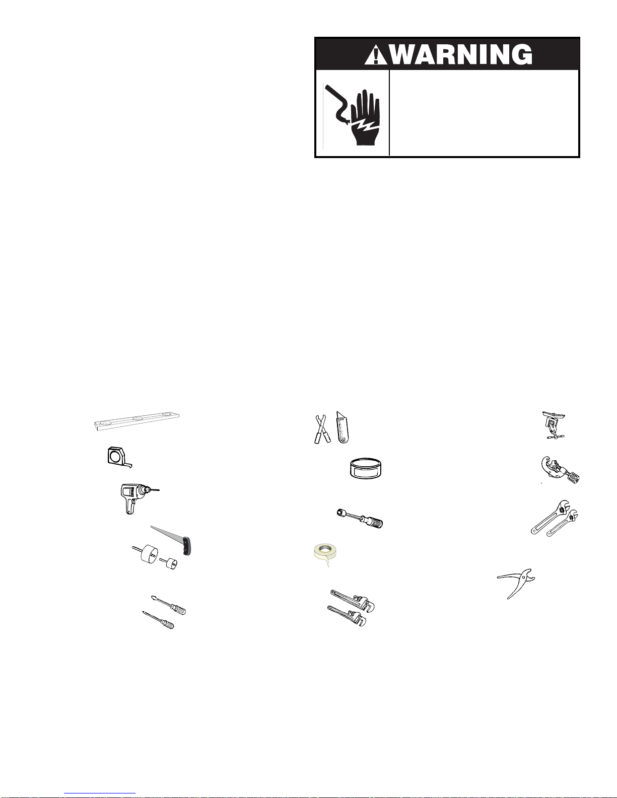
Tools Y ou Will Need
Level
Measuring
Tape
Electric Drill
Keyhole Saw or
1
/2”, 1 1/2”, and 2”
Hole Cutters
Slotted and Phillips
Screwdrivers
(magnetic tip
preferred)
Wire Stripper
or Knife
Pipe Joint compound
(for iron pipe
plumbing)
3
/16”, 1/4”, and 5/16”
Socket or Nut Driver
Teflon® Tape
(for iron pipe
plumbing)
2 Pipe Wrenches
(for iron pipe
plumbing)
Items You Will Need (Not Included)
Flaring Tool
(for copper
tubing)
Tube Cutter
(for copper tubing)
2 Adjustable
Wrenches
(for copper tubing)
Pliers
Drain Hose Clamp -1 1/4” Inner Diameter (ID)
3
90° Elbow Strain Relief Bushing
Wire Nuts (2)
/8” National Pipe Thread
2

Installation Tips
Read all instructions prior to installation
• Water , electric, and dr ain connections are not the same for all age, brand, or models of
dishwashers. Check and compare the location and length of your current utilities so you can
plan your new installation
• Each home installation is different and some parts may be needed to meet your individual
installation needs. You
angle fittings (not included) to make the final water connections to the dishw asher valve
to page 8).
(refer to pages 4 and 7).
will need
a 3/8” National Pipe Thread “Street L” or compatible right
(refer
• Clean dishes require an adequate supply of hot water . The water temperature must be
between 120°F (49°C) and 150°F (66°C).
diameter) copper tubing is recommended.
PSI [pounds-per-square-inch]) flow rate minimum (2 gallons/minute)
• A separate 15-20 amp, g rounded 120V AC electrical supply is required for your ne w
dishwasher .
Y ou may need a strain relief bushing and wire nuts or suitab le connectors
A minimum water supply line of
Reasonable water pressure is needed (20-120
(refer to page 8)
3
/8” (outside
.
(not included) for connecting house wiring to the dishwasher .
• If the dishwasher drain hose is connected to a garbage disposer for the first time ,
remember to knock out the plug in the disposer inlet. This plug is inside the inlet and y ou may
not see the plug from the outside
• The dishwasher drain hose to the house drain must have a 32” loop above the floor or a
suitable air gap must be used to pre vent water from siphoning out of the dishwasher and
causing washing problems
• Kinked water or drain lines can cause prob lems. Run lines with generous curves . Make sure
lines are long enough to allow for generous curves .
• Flush the water line prior to making final connections. A bunched towel over the end of the
line can help prev ent splashing. Let water drain into a bu cket or pan. This will pre vent
premature clogging of the filter screen in the inlet valve.
(refer to page 6).
(refer to page 7).
• The dishwasher will look, sound, and work better if it is properly leveled. Tak e time to
adjust the leveling legs so that all of them touch the floor and the dishw asher is lev el. Use #8
5
/8” Phillips head scre ws (supplied) to anchor dishwasher to countertop
x
and 13).
(refer to pages 9
3

Location and Rough-In
Figure 1
Most of the installation work should be done before
the dishwasher is moved into place. First, select a
location as close to the sink as possible for ready
access to water and drain lines. For proper operation
and appearance of the dishwasher, the cabinet
opening should be square and have dimensions as
shown in Figure 1. If the dishwasher is to be installed
in a corner, there must be sufficient clearance to open
the door as shown in Figure 2. A
of 2” is recommended.
Rough-in the water, electrical, and drain lines before
proceeding with the installation. The lines should run
straight to their connections on the dishwasher.
Note: Make sure that the lines do not cross in
front of the dishwasher motor or its legs.
minimum
clearance
Figure 2
4
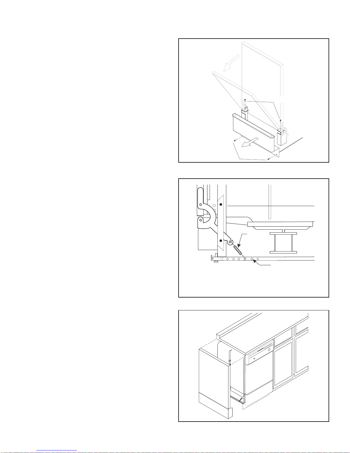
Preparing for Installation
1. Remove access panel assembly by opening door
all the way and removing two (2) screws on top of
access trim
2. Close door. Remove two (2) bottom attach screws
in access panel assembly.
(see Figure 3)
.
Figure 3
3. The access panel assembly can now be removed
by pulling it forward.
4. Install a 90° elbow (not included) into the water
valve. Use Teflon
the elbow into the valve fitting. Valve fitting is
National Pipe Thread.
®
tape or joint compound to seal
3
/8”
Adjusting Door Spring
Tension
The door springs are set at the factory to the proper
tension. To adjust spring tension, hook the springs in
a frame hole to the back of their original settings (
Figure 4
Door spring tension is correct when the door remains
horizontal in the fully opened position, yet rises to a
close with the slight lift of a finger.
).
see
Access Panel
Assembly
Bottom Attach Screws
Front of
Dishwasher
Move spring to rear of dishwasher
Access Trim Screws
Adjustable
Toeplate (not
shown)
Door
Spring
Frame Holes
to increase tension
Side Panel Kit
The dishwasher is not provided with a complete
enclosure. If the dishwasher is to be installed at the
end of a cabinet line, be certain that the sides and the
back are fully enclosed
kits are available from your dealer or distributor.
(see Figure 5)
Figure 4
. Side panel
Figure 5
5
 Loading...