

GE GSM1860FSS, GSM1800FBB, GSM1800FWW Installation Guide
GE Consumer & Industrial
Appliances
General Electric Company
No
(4/06)
WARNING
Installation
Built-In
Dishwasher
Instructions
If you have questions, call 800-GECARES or visit our website at: www.GEAppliances.com
BEFORE YOU BEGIN
Read these instructions completely and
carefully.
IMPORTANT – Observe all
governing codes and ordinances.
• Note to Installer – Be sure to leave these instructions
for the consumer’s and local inspector’s use.
• Note to Consumer – Keep these instructions with your
Owner’s Manual for future reference.
• Skill Level – Installation of this dishwasher requires
basic mechanical and electrical skills. Proper
installation is the responsibility of the installer.
Product failure due to improper installation is not
covered under the GE Appliance Warranty.
• Completion Time – 1 to 3 Hours. New installations
require more time than replacement installations.
IMPORTANT – The dishwasher
MUST be installed to allow for future removal from
the enclosure if service is required.
If you received a damaged dishwasher, you should
immediately contact your dealer or builder.
Optional Accessories – See the Owner’s Manual for
available custom panel kits.
FOR YOUR SAFETY
Read and observe all CAUTIONS and WARNINGS
shown throughout these instructions. While performing
installations described in this booklet, gloves, safety
glasses or goggles should be worn.
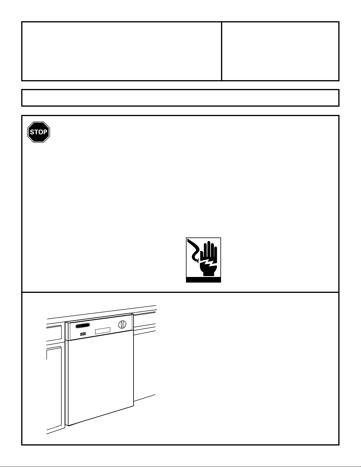
WARNING
To reduce the risk of electrical shock, fire,
or injury to persons, the installer must
ensure that the dishwasher is completely
enclosed at the time of installation.
READ CAREFULLY.
KEEP THESE INSTRUCTIONS.
Installation Preparation
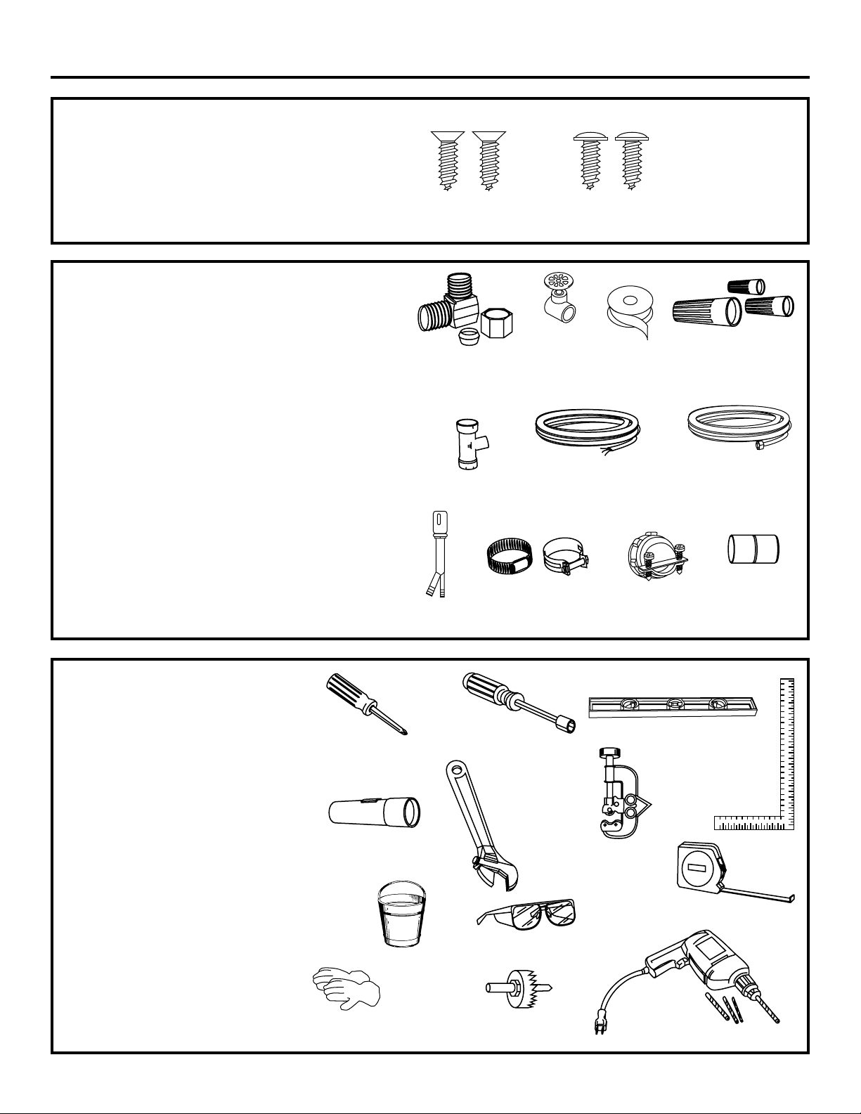
PARTS SUPPLIED:
Two #8 Phillips flat head wood screws, 5/8" long
to secure dishwasher to underside of countertop
(in literature package).
Two Phillips head, color matched toekick screws
(in literature package).
MATERIALS YOU WILL NEED :
Ferrule, compression nut and 90° Elbow (3/8"NPT external
thread on one end, opposite end sized to fit water supply)
Thread seal tape
UL Listed wire nuts (3)
Materials For New Installations Only:
Air gap for drain hose, if required
Waste tee for house plumbing, if applicable
Electrical cable or power cord, if applicable
Screw type hose clamps
Strain relief for electrical connection.
Hand shut-off valve
Water line 3/8" min. copper
Coupler for extending drain line, if applicable
2 Wood Screws
90° Elbow,
Ferrule and
Compression Nut
Waste Tee
Air Gap
2 Color Matched
Toekick Screws
Hand
Shut-Off
Valve
Electrical Cable
(or Power Cord, if applicable)
Screw Type
Hose Clamps
Thread
Seal Tape
Strain Relief
Wire Nuts (3)
Hot Water line
Coupler
TOOLS YOU WILL NEED:
Phillips head screwdriver
5/16" and 1/4" nutdriver
6" Adjustable wrench
Level
Carpenters square
Measuring tape
Safety glasses
Flashlight
Bucket to catch water when flushing the line
Gloves
For New Installations Only:
Tubing cutter
Drill and appropriate bits
Hole saw set
Phillips
Head
Screwdriver
Flashlight
Gloves
Bucket
1/4"
and 5/16"
Nutdriver
2
6" Adjustable
Wrench
Safety Glasses
Hole Saw Set
Level
Carpenters
Square
Tubing Cutter
Measuring Tape
Drill and Bits
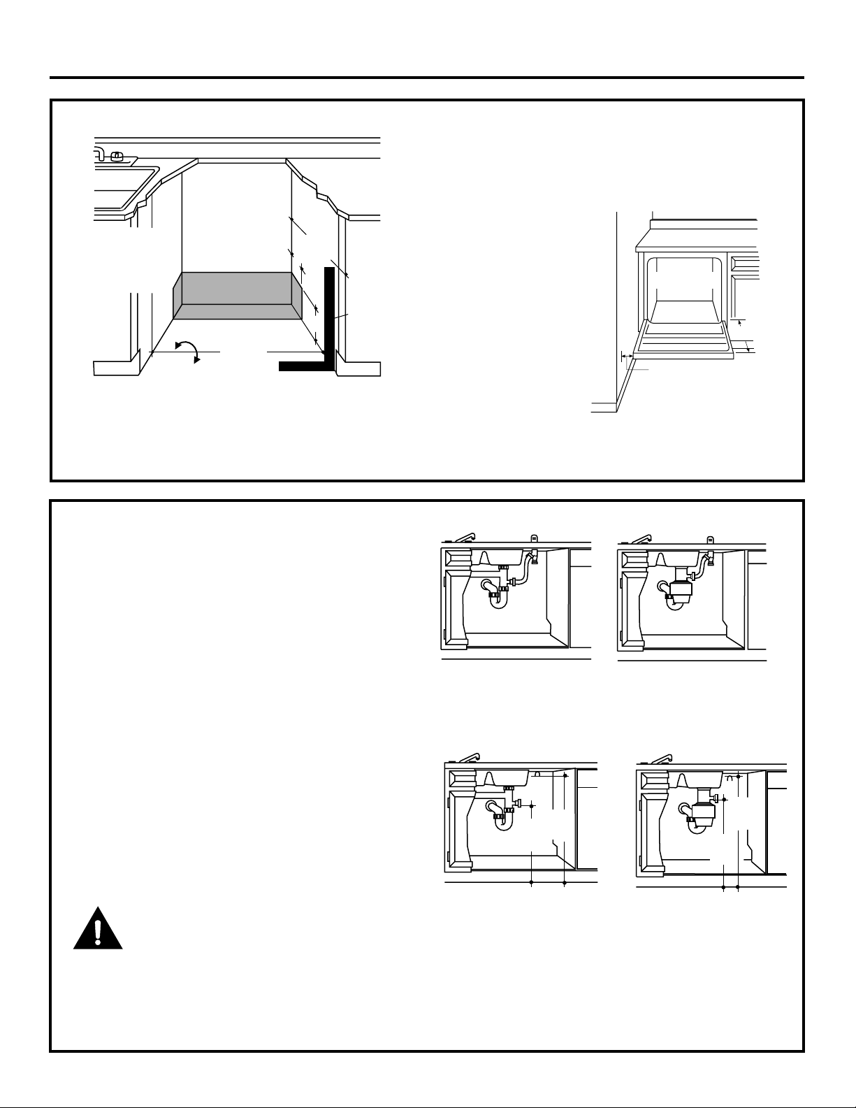
Installation Preparation
32"
Min.
18"
Min.
PREPARE DISHWASHER ENCLOSURE
34" to 35"
Underside of
Countertop
to Floor
17-5/8" Min.
18" Max.
Floor MUST
Figure A
be Even with
Room Floor.
Plumbing and Electric Service
Must Enter Shaded Area
• The rough cabinet opening must be at least 24" deep
and 17-5/8" to 18" wide. The opening should be 34" to
35" max. height.
24"
Min.
4
Cabinets
Square
6
and
Plumb
• The dishwasher must be installed so that drain hose is
no more than 10 feet in length for proper drainage.
• The dishwasher must be fully enclosed on the top,
sides and back, and must not support any part of the
enclosure.
CLEARANCES: When
installed into a corner,
allow 2" min. clearance
between dishwasher and
adjacent cabinet, wall or
other appliances. Allow
25-5/8" min. clearance
from the front of the
dishwasher for door
opening. Figure B
Note: ADA installation, (32-1/2") beneath 34" high countertops may be accomplished by adjusting the toekick and
leveling legs.
Countertop
Dishwasher
25-5/8"
Clearance for Door
Opening 2" Minimum
Figure B
DRAIN REQUIREMENTS
• Follow local codes and ordinances.
• Do not exceed 10 feet distance to drain.
• Do not connect drain lines from other devices
to the dishwasher drain hose.
• Dishwasher must be connected to waste line with an
air gap (not supplied) or 32" minimum high drain loop,
depending on local codes and ordinances to prevent
back flow into the dishwasher.
• Air gap must be used if waste tee or disposer connection is less than 18" above the floor to prevent siphoning.
DRAIN PREPARATION
The type of drain installation depends on answers to
the following questions:
■ Do local codes or ordinances require an air gap?
■ Will waste tee or disposer connection be less than
18" above the floor?
■ Will installation have a drain loop less than 32"
above floor?
If the answer to ANY of the 3 questions above is YES,
Method 1 MUST be used. Otherwise either Method 1
or Method 2 may be used. Figure C or Figure D.
CAUTION:
An air gap MUST BE USED if the drain hose is connected
to waste tee or disposer lower than 18" above the floor.
Failure to provide the proper drain connection height
with air gap or 32" minimum, high drain loop will result
in improper draining of the dishwasher.
Method 1 – Air Gap with Waste Tee or Disposer
Figure C
Method 2 – High Drain with Waste Tee or Disposer
Provide a method to attach drain hose to underside
of countertop.
32"
18"
Min.
Min.
Figure D
Install waste tee or disposer and air gap according to
manufacturer’s instructions.
CABINET PREPARATION
• Drill a 1-1/2" dia. hole in the cabinet wall within the
shaded areas shown in Figure A for the drain hose
connection. The hole should be smooth with no sharp
edges.
3
 Loading...