

Page 1
GE Consumer & Industrial
Technical Service Guide
November 2006
GE Washers With
Electromechanical Controls
and Mode Shifter Assembly
L
O
A
D
SIZE
H
O
O
BO
Y
E
XT
RA
L
A
RG
E
L
ARG
E
RE
G
UL
A
R
EWA4600G0
T
E
M
P
ER
A
T
U
R
E
OPT
I
ON
W
ARM
T
E
P
ID
S
H
O
T
D
E
L
IC
A
T
E
S
BURL
A
P
CO
L
D
COT
T
O
NS
P
R
E
W
E
A
S
YCARE
AS
H
DE
L
I
C
A
T
E
S
31-9146
GJRR4170H0
GJSR4160H0
WCSR4170G0
WHDRR418G0
WJRR4170G0
WJSR4160G0
WLRR4500G0
GE Appliances
General Electric Company
Louisville, Kentucky 40225
Page 2

IMPORTANT SAFETY NOTICE
The information in this service guide is intended for use by
individuals possessing adequate backgrounds of electrical,
electronic, and mechanical experience. Any attempt to repair a
major ap pli ance may result in personal injury and property
damage. The man u fac tur er or seller cannot be responsible for the
in ter pre ta tion of this in for ma tion, nor can it assume any liability in
connection with its use.
WARNING
To avoid personal injury, disconnect power before servicing
this prod uct. If electrical power is required for diagnosis or test
purposes, disconnect the power immediately after performing the
necessary checks.
RECONNECT ALL GROUNDING DEVICES
If grounding wires, screws, straps, clips, nuts, or washers used to
complete a path to ground are removed for service, they must be
returned to their original position and properly fastened.
GE Consumer & Industrial
Technical Service Guide
Copyright © 2006
All rights reserved. This service guide may not be reproduced in whole or in part
in any form without written permission from the General Electric Company.
– 2 –
Page 3

Table of Contents
AC Line Filter ........................................................................................................................................................................ 17
Agitator .................................................................................................................................................................................. 13
Belt ........................................................................................................................................................................................... 20
Brake Test .............................................................................................................................................................................36
Component Locator Views ........................................................................................................................................... 12
Control Panel ......................................................................................................................................................................14
Control Timer ......................................................................................................................................................................14
Control Features ...............................................................................................................................................................10
Cover/Lid Assembly .........................................................................................................................................................19
Diagnostics and Service Information ...................................................................................................................... 30
Drain Pump ..........................................................................................................................................................................20
Front Panel ........................................................................................................................................................................... 19
Harness Fuse ......................................................................................................................................................................23
Inverter/Motor .................................................................................................................................................................... 22
Inverter/Motor Error Codes .......................................................................................................................................... 33
Inverter/Motor Test .......................................................................................................................................................... 35
Leveling Legs ...................................................................................................................................................................... 13
Lid Switch .............................................................................................................................................................................18
Mode Shifter Coil Test .....................................................................................................................................................35
Motor and Drive System ................................................................................................................................................ 5
Nomenclature .................................................................................................................................................................... 4
Schematic ............................................................................................................................................................................ 37
Shaft and Mode Shifter Assembly ............................................................................................................................26
Shaft and Mode Shifter Overview ............................................................................................................................. 6
Shipping Rod ....................................................................................................................................................................... 13
Suspension .......................................................................................................................................................................... 23
Temperature Selector and Options Switches ......................................................................................................16
Tub Assembly .....................................................................................................................................................................24
Tub Cover .............................................................................................................................................................................. 24
Warranty .............................................................................................................................................................................. 38
Washer Components ...................................................................................................................................................... 13
Water Level Switch .......................................................................................................................................................... 15
Water Valve ......................................................................................................................................................................... 17
– 3 –
Page 4
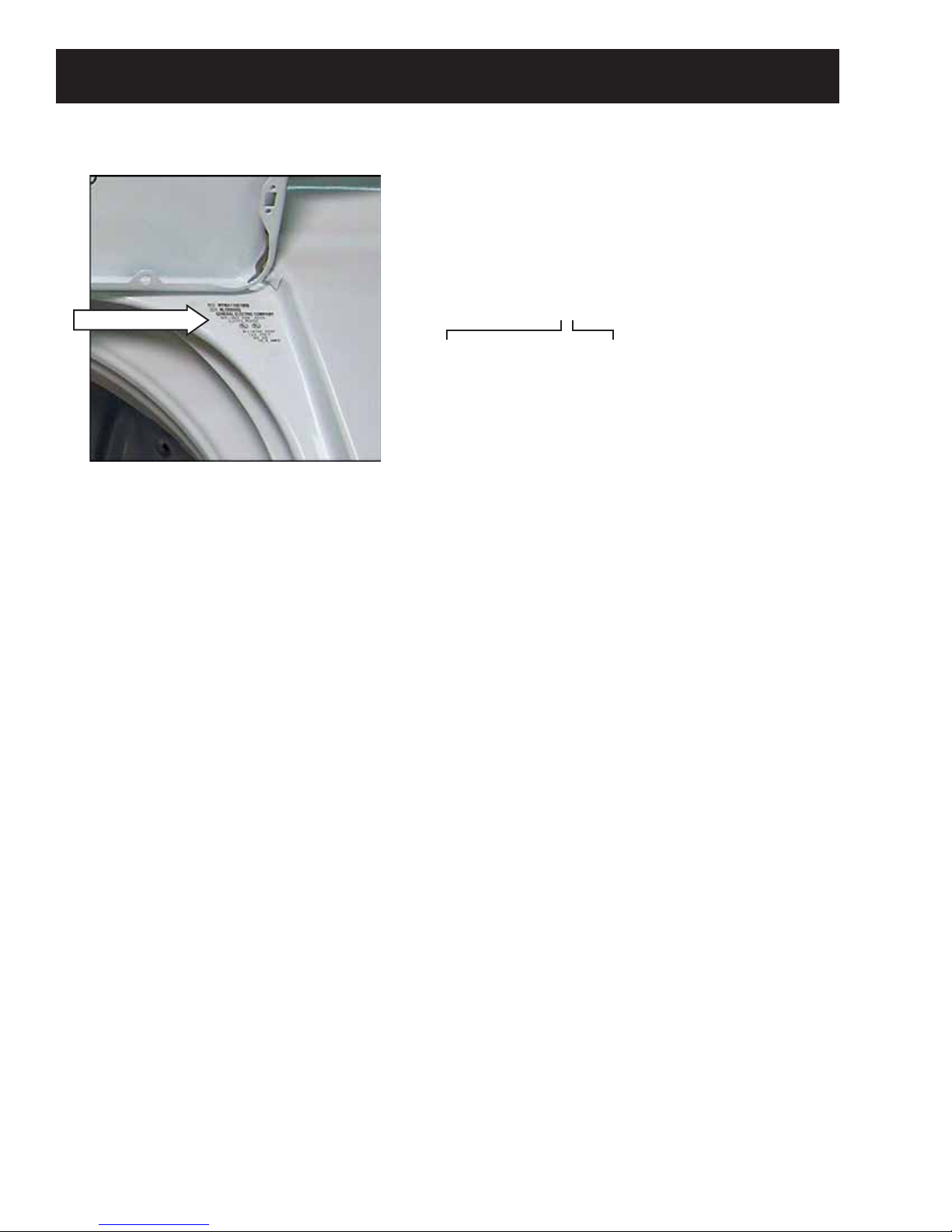
Nomenclature
The nomenclature tag is lo cat ed under
the lid in the right rear corner.
The mini-manual is located inside the
control panel.
Nomenclature
Serial Number
The fi rst two characters of the serial number
identify the month and year of manufacture.
Example: AL123456S = January, 2006
A - JAN 2006 - L
D - FEB 2005 - H
F - MAR 2004 - G
G - APR 2003 - F
H - MAY 2002 - D
L - JUN 2001 - A
M - JUL 2000 - Z
R - AUG 1999 - V
S - SEP 1998 - T
T - OCT 1997 - S
V - NOV 1996 - R
Z - DEC 1995 - M
The letter des ig nat ing
the year re peats every
12 years.
Example:
T - 1974
T - 1986
T - 1998
– 4 –
Page 5
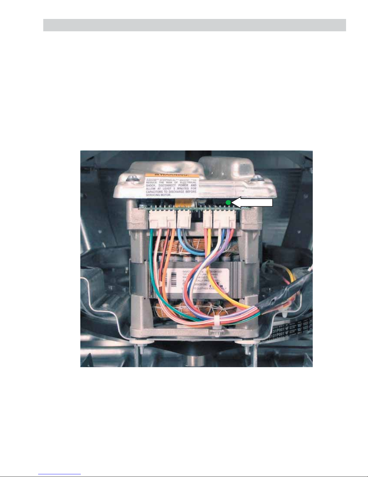
Motor and Drive System
The new GE washers incorporate a new motor and drive system. The 120 VAC input powers a three phase
induction inverter/motor assembly. The inverter produces approximately 340 VDC, which is pulse width
modulated (PWM) to control motor speed. There is no location to check inverter output voltage to the motor.
Voltage given is for information only. The motor is bidirectional, constantly reversing it’s direction to provide
agitation. The motor is connected by a belt to the shaft and mode shifter assembly. By energizing or deenergizing a coil, the mode shifter assembly engages or disengages the shaft and tube. This allows for
agitation and spin cycle modes.
Motor status is displayed through a series of fl ash codes from a green LED located on the front side of the
inverter just above the motor. These codes are stored in memory until cleared.
Green LED
Inverter/Motor
– 5 –
Page 6
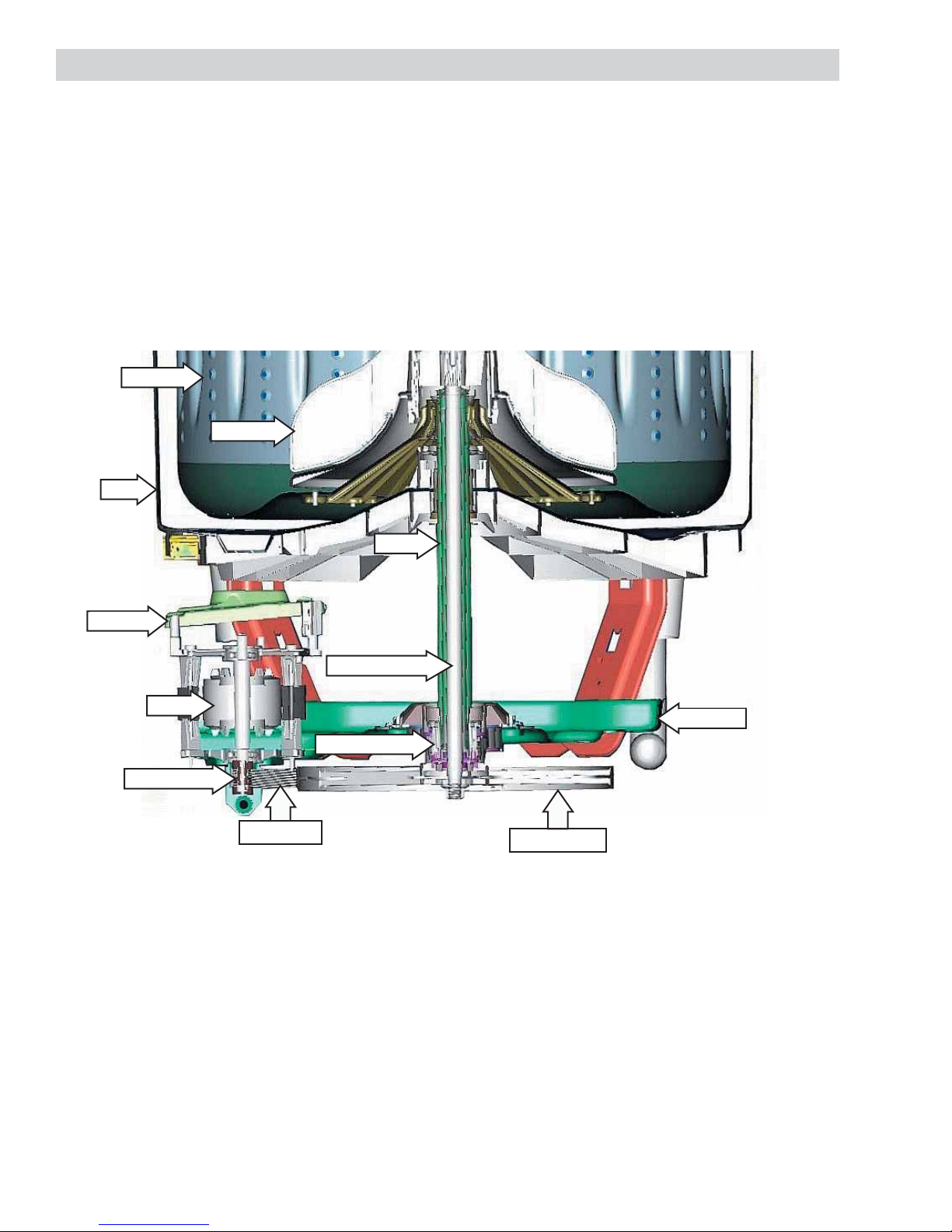
Shaft and Mode Shifter Overview
The shaft and mode shifter assembly consists of the shaft and tube, mode shifter cam, and mode shifter coil.
It operates in 2 distinct modes, spin and agitation.
The shaft and tube transfers power to the wash system. Motor power is transmitted to the shaft and tube
from the drive belt to the drive pulley. The drive pulley is attached to one end of the agitator shaft and the
agitator is attached to the other. The tube is fi xed to the washer basket at all times.
The mode shifter changes the shaft and tube from spin to agitation. In agitation mode, the tube is fi xed to the
platform and the agitator shaft rotates freely. In spin mode, the agitator shaft is fi xed to the tube and both
rotate together.
Basket
Agitator
Tub
Inverter
Motor Pulley
Motor
Drive Belt
Tube
Agitator Shaft
Platform
Mode Shifter
Drive Pulley
View from Right Side
(Continued next page)
– 6 –
Page 7

Shaft and Mode Shifter Assembly
Mode Shifter Coil
Mode Shifter Cam
Drive Shaft
Agitate Position
Mode Shifter Coil
Mode
Shifter
Cam
Drive Pulley
Note: Mode shifter coil energized for agitate mode; cam teeth disengaged from drive pulley.
Spin/Idle Position
Mode Shifter Coil
Note: Mode shifter coil de-energized for spin/idle mode; cam teeth engaged in drive pulley.
Mode
Shifter
Cam
Drive Pulley
(Continued next page)
– 7 –
Page 8

Mode Shifter Operation - Agitation
The mode shifter is controlled by the motor inverter circuit. When the washer starts the agitation cycle,
the inverter energizes the mode shifter coil. The magnetic field of the coil lifts the mode shifter cam,
disengaging it from the drive pulley. Without the cam engaged, the drive pulley rotates only the
agitator shaft.
MODE SHIFTER
AGITATE
PROGRAM
RUNS
(18 SEC)
At the beginning of the agitation cycle, the inverter energizes the mode shifter coil with
135 VDC (PWM) for approximately 18 seconds. This high voltage pulls the mode shifter
cam up from the drive pulley. During this time, the motor also rotates clockwise and
counterclockwise in short strokes to ensure the mode shifter cam has been released from
the drive pulley. This operation is called the Mode Shifter Agitate Program. It is normal to
hear metal-to-metal "clunking" sounds during this time as the cam and drive pulley
disengage. The washer runs this program when the agitation cycle first starts, when
power is restored if lost during agitation or when the user restarts the washer if paused.
Once the Mode Shifter Agitate Program has completed (18 seconds), agitation begins. During agitation,
the inverter continues to supply 30 VDC (PWM) to the mode shifter coil. This voltage is sufficient to hold
the mode shifter cam away from the drive pulley throughout the remainder of the agitation cycle.
The inverter motor controls the speed of agitation. The agitator stroke rate is approximately 30 strokes
per minute. This rate is the same for all cycles. The speed of the motor controls the arc. At fast speed,
the arc is approximately 360 degrees. At slower speeds, the arc is substantially less. It is the distance of
the arc that determines normal or gentle wash cycles.
Mode Shifter Operation - Spin
At the beginning of the spin cycle, the inverter runs a short sequence (approximately 30
MODE SHIFTER
SPIN
PROGRAM RUNS
(30 SEC
seconds) to make certain the mode shifter cam is engaged with the drive pulley. The
inverter does not supply voltage to the mode shifter coil during this sequence. Since the
coil is not energized, the spring loaded cam drops down into the teeth of the drive pulley.
During this time, the motor also rotates clockwise and counterclockwise in short strokes to
ensure the cam has engaged with the drive pulley. This 30 second operation is called the
Mode Shifter Spin Program. It is normal to hear metal-to-metal "clunking" sounds during
this time as the cam and drive pulley engage.
Notes:
If the washer is paused while in agitation, it is NORMAL to hear sounds for an additional 30 seconds as
the inverter control runs the Mode Shifter Spin Program to de-energize the coil and enter a pause state.
If the washer is in agitation and power is lost, the inverter control will run the Mode Shifter Agitate
Program when power is restored.
If the washer is in spin and power is lost, the inverter control will run the Mode Shifter Spin Program
when power is restored.
To help prevent out-of-balance conditions, the last 10 seconds of agitation on certain cycles will be
short, fast strokes to help redistribute the clothes load prior to entering the spin cycle.
(Continued next page)
– 8 –
Page 9
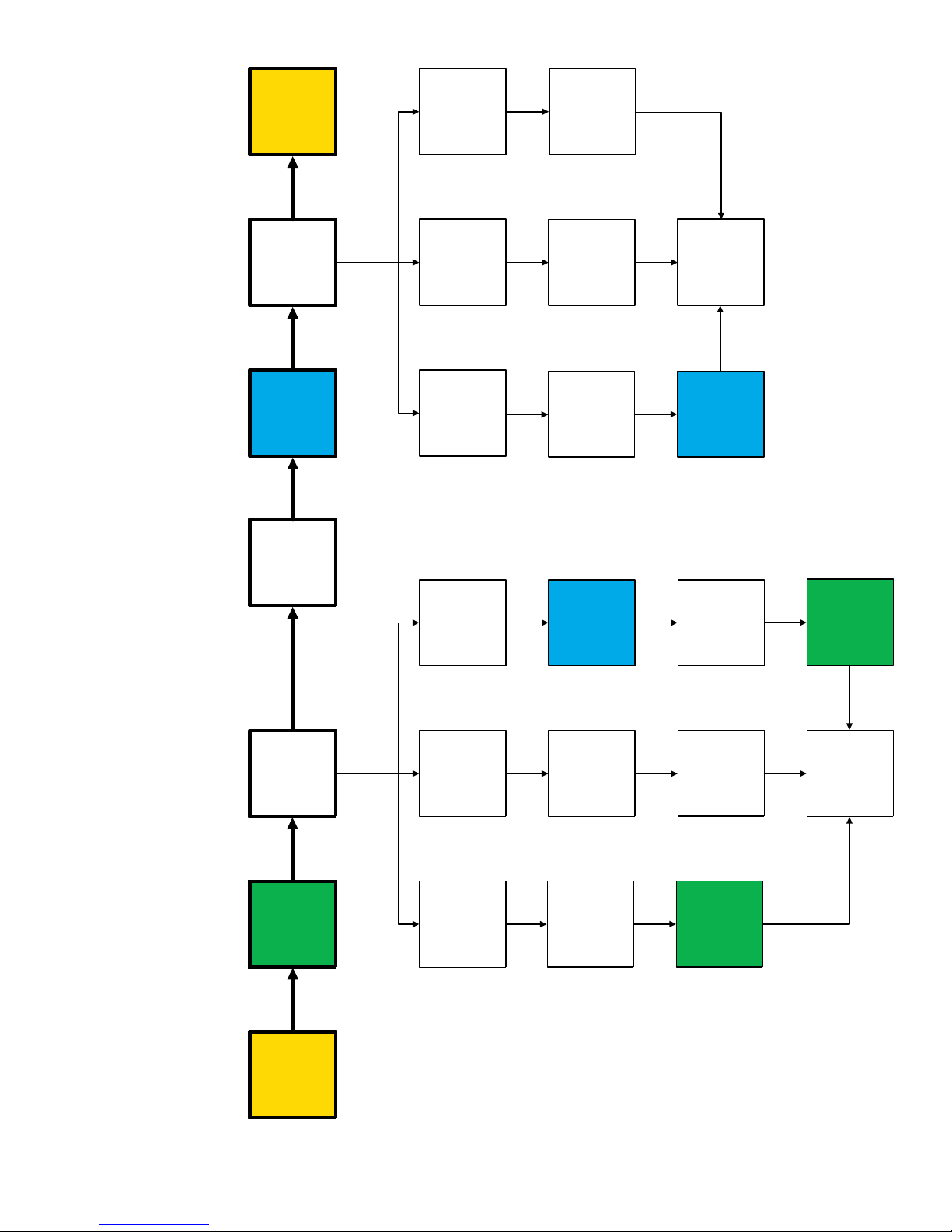
END
CYCLE
COMPLETED
SPIN BASKET
BEGINS
SPIN CYCLE
STOP
COASTS TO A
USER PRESSES
LID SWITCH
TIMER KNOB IN
OPENS
STOP
SPIN BASKET
COASTS TO A
STOPS
(7 SEC)
SPIN BASKET
USER
PULLS
KNOB
TIMER
CLOSED
LID SWITCH
OUT
SPIN
CYCLE
CONTINUES
SPIN
MODE SHIFTER
PROGRAM RUNS
CYCLE
AGITATION
CYCLE
AGITATION
(30 SEC
ENDS
BEGINS
POWER IS
LOST
USER
PRESSES
LID SWITCH
(7 SEC
STOPS
SPIN BASKET
TIMER
KNOB IN
OPENS
POWER IS
RESTORED
SPIN
MODE SHIFTER
PROGRAM RUNS
STOPS
MOTOR
MOTOR STOPS
(30 SEC
SPIN
MODE SHIFTER
PROGRAM RUNS
USER
PULLS
TIMER
CLOSED
LID SWITCH
(30 SEC)
KNOB OUT
AGITATE
PROGRAM
MODE SHIFTER
CYCLE
AGITATION
RUNS
(18 SEC)
CONTINUES
RUNS
(18 SEC)
AGITATE
PROGRAM
MODE SHIFTER
CYCLE
START
TUB FILLS
SELECTED
PRESSURE
SWITCH
Control Logic Flowchart
OPENS
POWER IS
LOST
– 9 –
POWER IS
RESTORED
AGITATE
PROGRAM
MODE SHIFTER
RUNS
(18 SEC)
Page 10
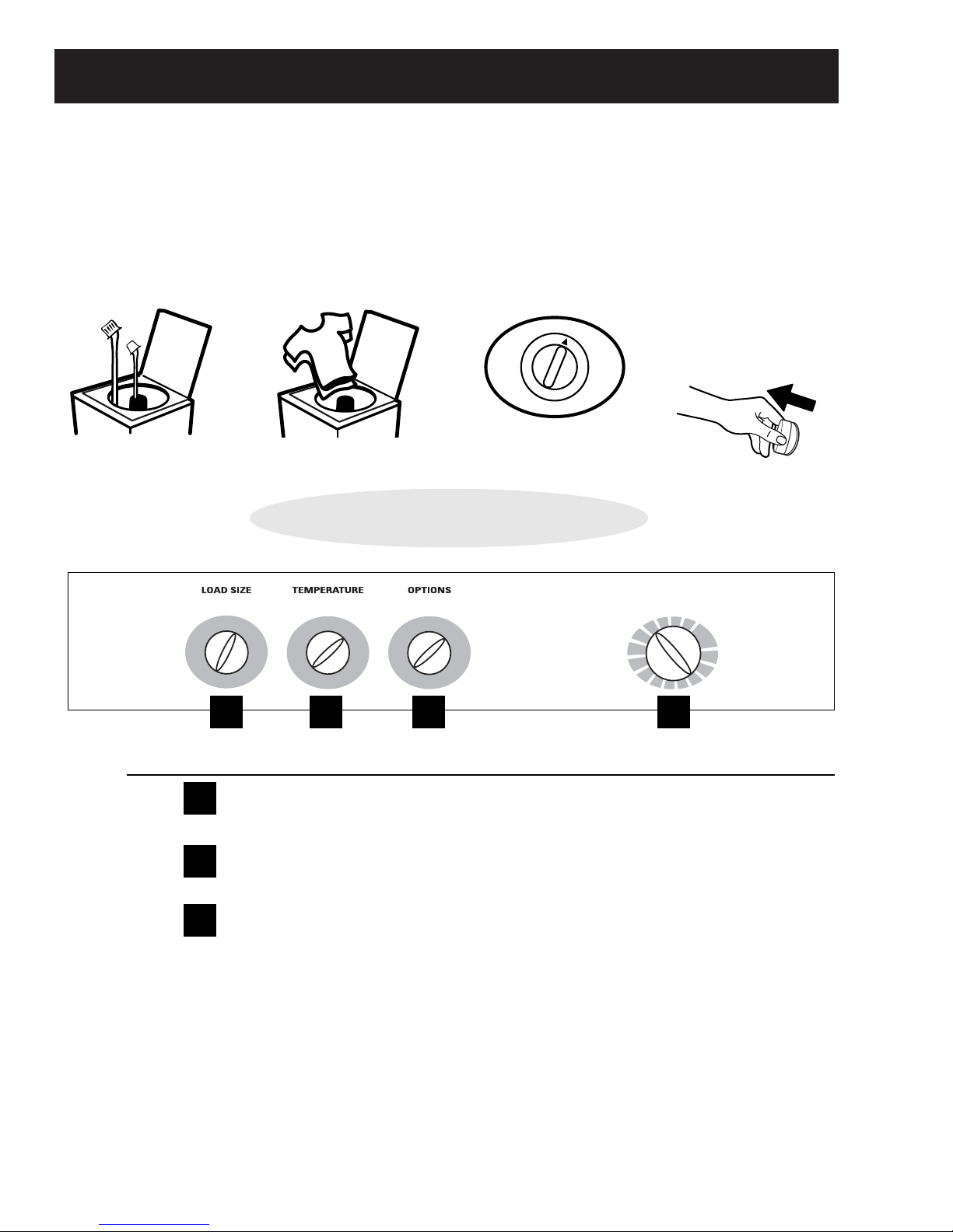
Control Features
• Add detergent
• Add diluted fabric
softener (on models
with a fabric
softener dispenser)
• Add clothes
• Select load size and
other wash options
• Select wash cycle
• Close lid
• Pull knob
Quick Start Guide
Load Size
Loosely load clothes no higher than the top row of holes in the washer basket. The water level should just cover
the clothes. Adjust the load size accordingly.
Temperature (on some models)
Select the water temperature for the wash and rinse cycles. Always follow fabric manufacturer’s care label or
instructions when laundering.
Options (on some models)
2nd Rinse Option
When you use extra detergent or bleach to clean heavily soiled clothes, you may want to use the 2nd Rinse
option. It provides a second deep cold rinse.
A
A
B
B
C
C
D
Step 1
Step 2
Step 3
Step 4
Controls
Features and appearance may vary between models.
GE Models
(Continued next page)
– 10 –
Page 11

Wash Cycle—Cycle Selector Knob
The chart below will help you match the wash cycle setting with your clothing. The chart is ranked from longest to
shortest cycle time and wash intensity.
Your washer may not have all these cycles. (Cycles vary by model.)
PREWASH For removing surface dirt from heavily soiled clothes. Make sure to follow with a
regular wash cycle.
D
COTTONS For heavy to lightly soiled cottons, household linens, work and play clothes.
or WHITES
EASY CARE For wrinkle-free and permanent press items, and knits.
DELICATES For lingerie and special-care fabrics with light to normal soil.
SPIN For draining the tub and spinning water out of the clothes.
RINSE SPIN For quickly rinsing chlorine, perspiration, stains, etc., out of clothes.
15 MIN/30 MIN For very soiled clothes. Begins with agitation, soaks for a specified period of time, then moves
AUTO SOAK through the rest of the cycle automatically.
2nd RINSE Provides an automatic, second deep rinse to thoroughly remove detergent or bleach from
your clothes.
– 11 –
Page 12

Front View
Component Locator Views
Pressure Hose
Suspension Rod
Inverter
Platform
Motor
Drive Pulley
Control Panel (in service position)
Water Level Switch
Drain Pump
Belt
Motor Pulley
Water Valve
AC Line Filter
Temperature
Selection
Switch
Options Switch
Timer
– 12 –
Page 13

Washer Components
WARNING: Sharp edges may be exposed when
servicing. Use caution to avoid injury. Wear Kevlar
gloves or equivalent protection.
Shipping Rod
There is a new location for the shipping rod. The rod
is inserted and removed through a hole located on
the lower right side of the cabinet and now passes
in front of the drain pump.
Shipping Rod
Rod Inlet Hole
Leveling Legs
The front legs are screw type and are adjusted
by turning the legs counterclockwise to increase
height. The rear leveling legs are contained in an
assembly and will level the rear of the washer left to
right.
To level the washer, tilt the washer forward to lift the
rear legs off the fl oor, then gently set it back down.
Adjust the front leveling legs to level the washer
front to back and left to right across the front.
Agitator
The agitator is a dual-action ratcheting type, which
sets on an air bell coupling. Remove the agitator
by grasping the bottom and sharply pulling up. To
protect from back injury, use agitator strap, part
number WX5X1326 or equivalent.
To align the agitator for reassembly, match the
grooves in the air bell to the grooves inside the
agitator. The fi ns on the outside of the agitator
are aligned with the grooves on the inside of the
agitator. To remove the air bell coupling, remove the
7
/
16
-in. bolt and lift coupling off the shaft.
The shipping rod passes through the chassis rod
brackets and the platform brackets.
Chassis Rod
Bracket
Platform Brackets
Chassis Rod
Bracket
– 13 –
Page 14

Control Panel
Control Timer
It is necessary to remove the control panel from the
backguard and place it in the service position to
access:
Control timer
•
Water level switch
•
Water valve
•
AC line fi lter
•
Caution: To prevent damage to the control panel,
place a protective pad on the cover/lid assembly.
To place the control panel in the service position:
Disconnect power.
1.
Remove the three ¼-in. hex-head screws from
2.
the rear of the control panel.
The control timer is mounted on the inside of the
control panel. It is held in place with a single ¼-in.
hex-head screw and 2 tab-locks.
To remove the control timer:
Disconnect power.
1.
Using a fl at blade screwdriver, remove the spring
2.
clip that attaches the timer knob to the timer
shaft.
Pull the knob and dial straight out from the
3.
timer.
Screwdriver
Clip
Rotate the top of the control panel forward
3.
approximately 1 inch and slide to the right to
unlock the 3 bottom locking tabs.
Lift the panel up and off the cover panel and rotate
4.
down.
Tab
Service Position
Dial
Knob
Place the control panel in the service position.
4.
(See Control Panel.)
(Continued next page)
– 14 –
Page 15

Remove the wire harness from the control timer.
5.
Remove the single ¼-in. hex-head screw.
6.
Wire Harness
Lift up slightly on the tab where the screw
7.
was located and rotate the timer clockwise (as
viewed from back) to release it from the 2 tablocks.
Water Level Switch
The minimum fi ll volume is 9 gallons. The water
•
level measures approximately 7½ inches (6
holes) above the bottom of the basket.
The maximum fi ll volume is 22 gallons. The
•
water level measures approximately 15 inches
above the bottom of the basket (between holes
2 and 3 from the top).
Minimum Fill Level
Control Timer Removed From Control Panel
Tab-lock
Tab-lock
To remove the water level switch:
Disconnect power.
1.
Remove the water level switch knob by gently
2.
pulling it outward.
Place the control panel in the service position.
3.
(See
Control Panel.)
– 15 –
Page 16

Note: The water level switch red and black wire
has a locking tab that must be depressed to be
disconnected. To remove this wire from the water
level switch, depress the clip using a small blade
screwdriver and pull the wire off the terminal as
shown.
ELECTRICAL TERMINAL
RELEASE/LOCKING TAB
Disconnect the 3 wires and the pressure hose
4.
attached to the water level switch.
Temperature Selector and Options Switches
To remove the temperature selector and options
switches:
Disconnect power.
1.
Remove the knob by gently pulling it outward.
2.
Place the control panel in the service position.
3.
(See Control Panel.)
Mark and disconnect the wires attached to the
4.
switch.
Press the plastic locking tab, rotate the switch
5.
counterclockwise, and pull the switch out of the
control panel.
Pressure Hose
Disconnect
Disconnect
Press the plastic locking tab, rotate the switch
5.
counterclockwise, and pull the switch out of the
control panel.
Temperature Selector Switch
Plastic Locking Tab
Options Switch
Plastic Locking Tab
Plastic Locking Tab
– 16 –
Page 17

Water Valve
The washer utilizes a 3-coil water valve. This
“triple water valve” meters water fl ow through
fi xed orifi ces. The chart below identifi es the
valves energized at each temperature setting and
approximate water temperatures obtained (+/- 5°F).
These temperatures are based on the DOE nominal
temperatures of 135°F for hot and 60°F for cold.
Setting Valve(s) Energized Temperature
Hot Hot Valve 135°F
Warm Hot Valve
Slow Cold Valve
Cool Hot Valve
Fast Cold Valve
Slow Cold Valve
Cold Fast Cold Valve 60°F
HOT SOLENOID
90°F
75°F
Remove the fi ll hoses from the water valve.
4.
Note: The fi ll funnel hose is diffi cult to remove.
Remove the fi ll funnel hose. Squeeze the clamp
5.
and slide it back. Carefully break the hose loose
by inserting a small fl at-blade screwdriver under
the hose to break the seal.
Remove the two ¼-in. hex-head screws that
6.
hold the valve to the cabinet.
Fill Funnel
Hose
SLOW COLD SOLENOID
FAST COLD SOLENOID
•
The water valve has a fl ow rate of
approximately 2.1 gallons (8 liters) per minute.
•
Each solenoid coil has an approximate
resistance value of 1.1K Ω.
•
When energized, there should be approximately
120 VAC at the appropriate coil.
The water valve is accessed by placing the control
panel in the service position. It is inserted and
retained in a cutout in the rear of the backguard
and held in place by 2 hex-head screws. It is only
available as a complete assembly.
AC Line Filter
The potential exists for the washer to cause
electronic devices in the vicinity to experience
disruption. In addition, electrical devices in the
area could cause erratic behavior in the washer
electronic control. To eliminate the likelihood of
disruption, the washer is equipped with a conductive
noise fi lter. Should interference with electronic
devices or erratic control behavior be reported,
suspect a problem with the fi lter. The ground wire
attached to the fi lter must have a good connection
for the fi lter to operate properly. Check to make
certain that the ground wire is connected properly
before replacing the fi lter.
The fi lter is accessed by placing the control panel in
the service position. (See Control Panel.)
Note: When untaping and disconnecting the wires
from the AC line fi lter, note wire locations.
To remove the water valve:
1.
Disconnect power.
2.
Disconnect the wiring from the solenoids.
3.
Place the control panel in the service position.
Control Panel.)
(See
AC Line Filter
– 17 –
Page 18

Lid Switch
The lid switch is installed in the cover assembly at
the right front corner of the lid recess. The switch is
held to the underside of the cover by a latch.
The lid switch is a safety feature that prevents the
washer from agitating or spinning when the lid
is open. The switch is closed by a magnet that is
attached to the lid. When the lid is shut, the magnet
will cause the switch to close the circuit, allowing
normal functions to occur. When the lid is opened,
the switch will open the circuit, which will prevent
agitating or spinning.
If the lid switch:
Is closed, it will provide 120 VAC to the inverter/
•
motor assembly at pin 6 of the C2 connector.
Is open, agitation and spin will not occur, but the
•
timer will continue to advance and the washer
will fi ll with water and drain at the appropriate
times in the cycle.
Was opened during a cycle, left open and the
•
timer fi nished the cycle, when the lid is closed
again, the inverter completes a spin algorithm to
ensure the mode shifter is de-energized.
Note:
The motor inverter control monitors lid switch
•
operation by monitoring voltage through pin 6
on connector C2.
As a safety measure, the inverter control
•
monitors lid openings by recording motor run
sequences. If the control runs 4 continuous
agitation/spin cycles (usually 2 complete wash
cycles) WITHOUT seeing the lid switch open, it
will shut down the motor and initiate a lid switch
error code. This error will prevent the motor from
operating until the problem is repaired.
To access the lid switch it is necessary to open the
lid and reach under the cover assembly. To release
it from the cover requires pressing the lid switch
latch in fi rmly and gently pushing the switch up. The
switch can then be lifted through the opening.
Bottom
View
Latch
Opens during agitation, the control will keep
•
the mode shifter energized. When the lid switch
closes while still in agitation, the washer will
resume agitation.
Opens during the execution of the mode shifter
•
agitate program, the control will stop the agitate
program and drop the mode shifter voltage to
0 VDC. When the lid switch is closed again, the
control will run the mode shifter spin program
and then re-run the agitate program from the
beginning.
Opens during the mode shifter spin program,
•
the control will stop the spin program. When the
lid is closed again, the control will run the spin
program from the beginning.
Lid Switch
– 18 –
Page 19

Front Panel
Cover/Lid Assembly
The front panel is a removable, galvanized sheet
metal section. The front panel is fastened at the
top by 2 metal spring clips, and at the bottom by 2
metal tabs, which protrude from the base of the unit
into slots in the panel bottom.
Most major mechanical components can be
accessed by removing the front panel.
To remove the front panel:
Locate 2 spring clips between the top cover and
1.
front panel by aligning a putty knife with left or
right edge of lid.
Insert the putty knife and push forward to
2.
release clips.
The cover/lid assembly is fastened at the front by
2 screws, on the sides by 2 metal catches, and at
the back by 3 locking tabs that protrude from the
bottom of the control panel.
Note: Do not allow lid to swing open when cover/lid
assembly is removed. Damage may result.
To remove the cover/lid assembly:
Remove the front panel. (See Front Panel.)
1.
Remove the lid switch. (See Lid Switch.)
2.
Remove the two ¼-in. hex screws securing the
3.
front of the cover/lid assembly to the cabinet.
Rotate the front panel forward and lift off the
3.
bottom tabs.
Pull the top cover toward you while lifting up the
4.
front edge to release the side catches. Slide the
top cover to the left to release from the 3 tabs.
– 19 –
Page 20

Drain Pump
Belt
The drain pump is coupled to a 120 VAC, 60 Hz, 85
watt motor. The pump motor has an approximate
resistance value of 12 Ω.
Note: If a wash cycle has started and the customer
stops the washer by pushing in on the timer knob,
the pump will not drain any water in the tub. The
washer will go through a spin algorithm to deenergize the mode shifter and shut down. The water
stays in the tub.
To remove the pump:
Note: Water will remain in hoses even when the tub
appears empty. Use care to avoid water spills.
Disconnect power to the machine.
1.
Lower the drain hose into a small bucket to
2.
remove any water remaining in hose.
Remove the front panel. (See
3.
4.
Disconnect the pump wires.
Front Panel.)
Since the belt provides constant tension, there is
•
no need for adjustments (an adjustment method
is not provided).
A worn or damaged belt can result in excessive
•
brake time and will initiate a motor inverter
slipping belt error code. This code will prevent
the inverter/motor from operating.
To replace the drive belt it may be helpful to use
•
the belt install tool (part number WX05X10102).
Belt Install Tool Kit
5.
Pinch off the black sump hose to prevent water
spills.
6.
Remove hose clamps and hoses from the pump.
7.
Remove two
3
/
8
-in. hex-head screws.
Sump Hose
Drain Pump
Pump Wires
To replace the drive belt using the tool kit:
Note: If not using the belt install tool, follow steps 1
through 3, and 6 through 7. Remove wire tie after
step 7.
Disconnect power.
1.
Remove the front panel. (See Front Panel.)
2.
Center belt on drive pulley and secure tightly
3.
with wire tie as shown on following page. Align
wire tie as shown.
Stretch the belt install tool to fi t over the end of
4.
the motor shaft. (See Figure A.)
Slide belt install tool upward until it snaps into
5.
the fi rst groove of the motor shaft. (See Figure
B.)
Center belt on motor shaft grooves and slowly
6.
turn drive pulley clockwise.
Continue rotating drive pulley until belt is fully
7.
engaged.
8.
– 20 –
Remove wire tie and belt install tool.
(Continued next page)
Page 21

Note:
A new belt will be slightly smaller than the drive pulley.
•
A belt that has been installed on the drive pulley will stretch
•
to the diameter of the pulley over time. This is normal and
does not indicate a bad belt.
New Belt on Pulley
– 21 –
Page 22

Inverter/Motor
The inverter/motor assembly receives 120 VAC,
which the inverter converts to approximately 340
VDC. The inverter then uses pulse width modulation
(PWM) to supply the motor with an AC varying
frequency to control speed.
Note: There is no location to check inverter output
voltage to the motor. Voltage given is for information
only.
The inverter/motor assembly consists of a motor
and inverter board. A brake resistor is molded into
the underside of the inverter cover and absorbs
energy from the reversing of the motor during the
braking cycle. A Hall effect sensor mounted on the
inverter board measures motor speed (RPM).
The motor and inverter are available only as an
assembly.
WARNING: Do not attempt to remove the inverter
cover to service the board or brake resistor.
To remove the inverter/motor:
1.
Disconnect power.
WARNING: Exposed terminals, inverter board, and
rotating parts may cause injury and/or electrical
shock. To reduce the risk of electrical shock,
disconnect power and allow at least 5 minutes for
capacitors to discharge before servicing motor.
An audible clicking sound will be heard when the
inverter capacitor discharges (inrush relay closing).
2.
Remove the front panel. (See
Disconnect 3 wire harnesses from the motor.
3.
Release the compression tabs that attach the
4.
Front Panel.)
wire retainer to the front of the platform.
Remove the belt by rolling it off the bottom of
5.
the motor pulley.
Remove the front two
6.
3
/
8
-in. motor nuts and
loosen the rear 2 nuts.
Note:
•
There is a nonresettable fuse, located in the
motor harness along the right side of the
cabinet. If the fuse is open, agitate, spin, and
mode shifting will not occur.
•
If the motor speed sensor fails, the motor will
not run.
•
If the motor is not operating, the washer will still
fi ll with water, advance the timer, and drain.
•
If during an agitation cycle, water leaks from the
tub and resets the pressure switch,
the inverter
control stops agitation and goes through the
mode shifter spin program to de-energize
the cam and the washer starts to refi ll with
water. The motor will not run again until the
pressure switch is satisfi ed, at which time the
inverter control will run the mode shifter agitate
program.
If the mode shifter circuit fails or the coil opens,
•
the tub will move back and forth with the
agitator during the wash cycle.
Cover
Inverter
Motor
Drive
Pully
Disconnect
Wire Retainer
Belt
(Continued next page)
– 22 –
Page 23

Note: Minimal clearance exits between the 2 rear
3
/
8
-in. motor nuts, isolators, and the drive pulley.
Raise the front of the motor high enough to
7.
disengage the motor alignment pin from the pin
locator hole then slide the motor forward so that
the 2 rear spacers clear the drive pulley.
Harness Fuse
A nonresettable 10-amp fuse is wired in the neutral
side of the line. The fuse is wrapped in the motor
harness located along the right side of the cabinet.
Remove the rear two
8.
Tilt the top of the motor towards the shaft
9.
3
/
8
-in. motor nuts.
and tube. Lift and remove the motor from the
platform.
WARNING: The motor casing is NOT at chassis
ground potential. Voltage may be present on the
motor casing. To prevent electrical shock, do not
touch the motor when connected to power.
Caution: To prevent motor or inverter board
damage, make certain all isolators are in place
when reinstalling motor to platform.
Note: When replacing the motor, ensure the motor
alignment pin is fully inserted in the pin locator hole
in the platform before tightening motor nuts.
N
INVERTER
C7
If the fuse is open, agitate, spin, and mode shifting
do not occur. Check the fuse connections and wiring
harness.
Caution: Bending the harness can damage the fuse.
If the harness is OK, check the inverter/motor; a
shorted brake resistor or internal motor problem
can cause fuse failure.
Alignment Pin
Pin Locator Hole
Note: When replacing a motor, check its brake
operation. Place washer in a spin cycle and lift the
lid after it has reached full speed. The basket should
stop within 7 seconds. If time exceeds 7 seconds
check the lid switch operation, and check the belt
for worn ribs or slippage due to residue on the belt
or pulleys.
Note: If the fuse is open, use harness fuse kit (part
number WH49X10041). Instructions are included
with the kit.
Suspension
The tub and motor assembly (spin basket, outer tub,
inverter motor, shaft and mode shifter assembly
and platform) is suspended by four rod and spring
assemblies. The rod and spring assemblies are
attached to each corner of the cabinet. They
extend down and connect to the platform. This
arrangement provides limited movement to the tub
and motor assembly, independent of the cabinet
when agitating and spinning, thus reducing cabinet
travel and vibration. Front and rear suspension rod
compressions vary to compensate for different
model characteristics. The rods are color-coded to
ensure that they are replaced in the correct position.
The outer tub has 4 dampening straps attached to
the four corners of the cabinet. These straps prevent
excessive outer tub rotation and movement during
the wash cycle.
– 23 –
Page 24

Tub Cover
Tub Assembly
Note: The tub cover can be replaced without
removing the tub.
To remove the tub cover:
Remove the front panel. (See Front Panel.)
1.
Remove the cover/lid assembly. (See
2.
Assembly.
Disconnect 4 dampening straps from the tub
3.
cover by removing four
)
5
/
16
-in. hex-head screws.
Tub Cover
Cover/Lid
Note: The motor can be replaced without removing
the tub. (See Inverter/Motor.) The tub assembly must
be removed when replacing the spin basket, outer
tub, or certain speed drive components.
To remove the tub assembly:
Disconnect power.
1.
Lower the drain hose into a small bucket to
2.
remove any water remaining in the tub.
Remove the front panel. (See Front Panel.)
3.
Remove the cover/lid assembly. (See Cover/Lid
4.
Assembly.)
Remove the tub cover. (See Tub Cover.)
5.
Remove the agitator. (See Agitator.)
6.
Remove the
7.
7
/
16
-in. hex-head bolt and air bell
coupling from the agitator shaft.
Remove the air bell.
8.
Release the cover from the outer tub by lifting
4.
the 8 tabs.
Raise the front of the cover to clear the front
5.
cabinet brace and tilt the tub forward.
Carefully lift and remove the cover from the tub.
6.
Tab (1 of 8)
Note: When replacing air bell, tighten the
head bolt to 90 in. lbs. of torque.
7
/
16
-in. hex-
(Continued next page)
– 24 –
Page 25

Caution: Use only a rubber mallet, dead blow
hammer, or impact wrench to remove the hub nut.
Use of a steel head hammer may result in damage
to the spin basket.
Note: The word “LOOSEN” and an arrow appear on
the hub nut. Turn clockwise to remove.
Remove the left-hand thread, 1
9.
11
/
16
-in. nut
using an impact wrench or a hub nut wrench
(WX5X1325) and rubber mallet or dead blow
hammer.
WARNING: Exposed terminals, inverter board and
rotating parts may cause injury and/or electrical
shock. To reduce the risk of electrical shock,
disconnect power and allow at least 30 seconds
for capacitors to discharge before servicing motor.
A distinct click can be heard from the relay on the
inverter when the capacitor is discharged.
Disconnect the 2 outer motor harness
10.
connectors, and the ¼-in. hex-head screw that
attaches the platform ground wire.
Release the compression tabs that attach the 3
11.
motor wire harness retainers to the front of the
platform.
Disconnect
The hub nut must be torqued to 75 ft. lbs. To ensure
the hub nut is tightened suffi ciently when using a
hub nut wrench, align the wrench with the holes in
the basket and use them as a guide to determine
when the nut will not move any further. Impact
wrenches are set to more than 75 ft. lbs. and should
tighten the nut suffi ciently.
Platform Ground Wire
Wire Retainer (1 of 3)
Remove the water pressure switch hose from
12.
the outer tub.
Pinch off the black sump hose to prevent water
13.
spills.
Loosen the
14.
5
/
16
-in. screw-type hose clamp and
remove the sump hose at the tub.
(Continued next page)
– 25 –
Page 26

Note: The front and rear rod and spring assemblies
have different spring compressions and should not
be interchanged. The rods are color-coded to ensure
they are replaced in the correct position. Note the
color location before removing.
Disengage the front rod and spring assemblies
15.
by raising the tub and removing the spring
assemblies from the platform.
Rod and Spring
Assembly
Shaft and Mode Shifter Assembly
The shaft and mode shifter assembly consists of the
shaft and tube, mode shifter cam, and mode shifter
coil. These parts come only as an assembly.
WARNING: Do not attempt to disassemble the shaft
and mode shifter assembly.
To remove the shaft and mode shifter assembly:
Remove the tub assembly from the cabinet. (See
1.
Tub Assembly.)
Remove the split ring and fl at washer from the
2.
drive assembly.
Note: The tub assembly will now lean forward.
This allows clearance to reach behind the tub and
access the rear rod and spring assemblies.
Disengage the rear rod and spring assemblies
16.
by raising the rear of the tub and removing the
spring assemblies from the platform.
Pull the top of the tub assembly toward the front
17.
of the cabinet, then remove the basket from the
tub.
Split Ring
Flat Washer
Note: A new seal (part number WH02X10032) is
included with a replacement tub or shaft and mode
shifter assembly. Replace the seal when the tub has
been separated from the shaft and mode shifter
assembly.
Remove the tub assembly from the cabinet and
18.
place it on a protected surface.
(Continued next page)
– 26 –
Page 27

Invert the tub assembly on a protected surface
3.
and remove the plastic tie that holds the fl ood
hose to the platform.
Plastic Tie
Disconnect the mode shifter coil wire harness
4.
from the motor.
Release the compression tab that attaches the
5.
mode shifter coil wire harness retainer to the
front of the platform.
Run the belt off the drive pulley and remove the
6.
¾-in. pulley nut.
Pulley Nut
Note: When replacing pulley, tighten pulley nut to
275 in. lbs. of torque.
Note: In the following step, after removing the pulley
nut, it may be helpful to grab the center core of the
drive pulley with one hand and gently tap one of the
drive pulley arms with a hammer. The drive pulley
will “pop” off the tapered shaft.
Retainer
Coil Wire Harness
Remove the drive pulley from the shaft and
7.
mode shifter assembly.
Center Core
of Pulley
(Continued next page)
– 27 –
Page 28

3
/
8
8.
Remove the three
-in. hex-head bolts from the
bottom of the platform.
Remove the four ½-in. hex-head bolts that
9.
attach the platform to the tub.
Lift the platform from the tub.10.
Place the platform upright on a protected
11.
surface and remove the tub bearing washer
from the tube.
Tub Bearing Washer
(Continued next page)
– 28 –
Page 29

Remove the inverted single
12.
from the top of the platform.
3
/
8
-in. hex-head bolt
Note: Torque the four
lbs. when reinstalling.
3
/
8
-in. hex-head bolts to 90 in.
Inverted Bolt
Lift the shaft and mode shifter assembly from
13.
the platform.
Shaft and Mode
Shifter Assembly
– 29 –
Page 30

Diagnostics and Service Information
Timer Chart
(Continued next page)
– 30 –
Page 31

Motor Circuit - High Speed Agitate
L1
N
Motor Circuit - High Speed Spin
L1
N
(Continued next page)
– 31 –
Page 32

Motor Circuit - Low Speed Agitate
L1
N
Motor Circuit - Low Speed Spin
L1
N
– 32 –
Page 33

Inverter/Motor Error Codes
Inverter/Motor Signal LED
LED On
An LED beneath the inverter cover can be viewed for diagnostic testing.
•
When motor is operating normally, and running, the LED blinks at a constant rate of ½ second on and ½
•
second off.
When motor is operating normally, and idle, the LED blinks at a constant rate of 1 second on and 1
•
second off.
Motor/Control error condition – LED is on for .25 seconds and off for .25 seconds for a specifi ed number
•
of times, during a 6-second period. The 6-second cycle repeats continuously.
(Continued next page)
– 33 –
Page 34

Inverter/Motor Signal LED Errors
When excessive stop time is encountered, more than 25 seconds, the LED blinks once for ¼ second and
•
then off for the remainder of a 6-second period.
When a broken coupling or slipping belt is detected, the LED blinks twice at a rate of ¼ second on and ¼
•
second off for the remainder of a 6-second period.
When an inverter ROM checksum error is detected, the LED blinks 3 times at a rate of ¼ second on and
•
¼ second off for the remainder of a 6-second period.
When a mode shifter error occurs, the LED blinks 4 times at a rate of ¼ second on and ¼ second off for
•
the remainder of a 6-second period. The motor continues to operate with this error.
When a locked rotor is detected, the washer will sit idle for 15 seconds and retry. If the motor does not
•
operate after 3 tries, the LED blinks 6 times at a rate of ¼ second on and ¼ second off for the remainder
of a 6-second period.
When a lid error is detected by the lid switch counter, 4 agitate/spin pairs with no change in state of lid
•
switch, the LED blinks 7 times at a rate of ¼ second on and ¼ second off for the remainder of a 6-second
period.
When an over temperature condition is detected in motor, the LED blinks 8 times at a rate of ¼ second
•
on and ¼ second off for the remainder of a 6-second period. The motor continues to operate at reduced
performance levels.
When a brake resistor circuit error is detected in motor, the LED blinks 9 times at a rate of ¼ second on
•
and ¼ second off for the remainder of a 6-second period. Maximum spin speed is limited to 50 RPM.
Critical Errors, #1, #2, & #7, will prevent inverter/motor from operating.
•
To clear errors, disconnect power until an audible clicking sound is heard when the inverter capacitor
discharges (approximately 15 seconds). Open and close the lid 5 or more times in any 12-second period
within the fi rst 30 seconds of power-up. Errors will not clear if washer is in either agitate or spin mode.
– 34 –
Page 35

Inverter/Motor Test
Voltage readings:
C2 Pin 1 = Ground
C2 Pin 3 = Neutral
C2 Pin 5 to Pin 3 = 120 VAC
C2 Pin 6 to Pin 3 = 120 VAC with lid switch
closed
C7 Pin 1 to Pin 2 = 135 VDC*
C7 Pin 1 to Pin 2 = 30 VDC*
Low Speed Agitate
C2 Pin 3 to C4 Pin 2 = 120 VAC
C2 Pin 3 to C4 Pin 4 = 120 VAC
High Speed Agitate
C2 Pin 3 to C4 Pin 3 = 120 VAC
C2 Pin 3 to C4 Pin 4 = 120 VAC
Low Speed Spin
C2 Pin 3 to C4 Pin 2 = 120 VAC
C2 Pin 3 to C4 Pin 5 = 120 VAC
High Speed Spin
C2 Pin 3 to C4 Pin 3 = 120 VAC
C2 Pin 3 to C4 Pin 5 = 120 VAC
L1
C4
C2
C7
* 135 VDC is present for approximately 15
seconds at the beginning of the agitate
program. 30 VDC is present during the
remainder of the agitate cycle.
Note: All electrical testing is done at harness
plugs.
Mode Shifter Coil Test
C4
C2
LID SWITCH
L1
C7
N
Note: The mode shift coil connects to C7 connector on inverter/motor assembly. Unplug C7 connector and
check continuity. Mode shift coil resistance value is approximately 98Ω @ room temperature (77ºF).
– 35 –
Page 36

Brake Test
The brake resistor is
permanently molded
into the underside of
the inverter cover.
Tub should stop spinning 7 seconds after lid is lifted.
•
If the tub takes approximately 10 seconds to stop, check drive belt for wear.
•
If tub coasts to stop, brake resistor has failed and inverter/motor assembly must be replaced.
•
If the tub takes longer than 25 seconds to stop, the inverter will initiate a brake resistor error code. (See
•
Inverter/Motor Error Codes.)
– 36 –
Page 37

Schematic
WARNING: Disconnect electrical power before servicing.
Caution: Label all wires prior to disconnection. Wiring errors can cause improper and dangerous operation.
Verify operation after servicing.
C4
C7
C2
– 37 –
Page 38

Warranty
ı
ı
ı
ı
ı
– 38 –
 Loading...