

Page 1

GE Fanuc Automation
Computer Numerical Control Products
Series 15 – Model B
for Lathe
Operator's Manual (Operation)
GFZ-62554E-1/01 September 1994
Page 2

Warnings, Cautions, and Notes
as Used in this Publication
Warning notices are used in this publication to emphasize that hazardous voltages, currents,
temperatures, or other conditions that could cause personal injury exist in this equipment or
may be associated with its use.
In situations where inattention could cause either personal injury or damage to equipment, a
Warning notice is used.
Caution notices are used where equipment might be damaged if care is not taken.
GFL-001
Warning
Caution
Note
Notes merely call attention to information that is especially significant to understanding and
operating the equipment.
This document is based on information available at the time of its publication. While efforts
have been made to be accurate, the information contained herein does not purport to cover all
details or variations in hardware or software, nor to provide for every possible contingency in
connection with installation, operation, or maintenance. Features may be described herein
which are not present in all hardware and software systems. GE Fanuc Automation assumes
no obligation of notice to holders of this document with respect to changes subsequently made.
GE Fanuc Automation makes no representation or warranty, expressed, implied, or statutory
with respect to, and assumes no responsibility for the accuracy, completeness, sufficiency, or
usefulness of the information contained herein. No warranties of merchantability or fitness for
purpose shall apply.
©Copyright 1994 GE Fanuc Automation North America, Inc.
All Rights Reserved.
Page 3
B-62554E-1
/Ol
PREFACE .
PREFACE
The models covered by this manual, and there abbreviations are
Product name
FANUC Series
Manuals related to FANUC Series 1 S-MODEL B are as follows.
This manual is marked with an asterisk
FANUC Series
FANUC Series i
FANUC Series
FANUC Series
FANUC Series
FANUC Series
*
FANUC Series
FANUC Series 1 &MODEL B PARAMETER MANUAL
FANUC Series 1 S-MODEL B MAINTENANCE MANUAL
FANUC PMC-MODEL
FANUC PMC-MODEL
FANUC PMC-MODEL
FANUC PMC-MODEL PA1 /PA3/RAl
FANUC PMC-MODEL
FANUC Series
FANUC Series
CONVERSATIONAL AUTOMATIC PROGRAMMING FUNCTION FOR LATHE
(Series 16, Series
CONVERSATIONAL AUTOMATIC PROGRAMMING FUNCTION FOR MACHINING CENTER
(Series
15-MF,
CONVERSATIONAL AUTOMATIC PROGRAMMING FUNCTION FOR MACHINING CENTER
(Series
15-MF,
15-MB
15-MODEL
15-MODEL
15-MODEL
15-MODEL
15-MODEL
l5-MODEL
15-MB
Series
Series 15iVlFB) OPERATOR’S MANUAL (B-61264E)
1!5-TB
DESCRIPTIONS
5-MODEL
15-MODEL
B CONNECTION MANUAL (B62073E)
B CONNECTION MANUAL (BMI Interface) (B-62073E-1)
B For Lathe OPERATOR’S MANUAL (PROGRAMMING)
B For Lathe OPERATOR’S MANUAL (OPERATION)
B For Machining Center OPERATOR’S MANUAL
B For Machining Center OPERATOR’S MANUAL
N/NA
PROGRAMMING MANUAL (LADDER LANGUAGE) (B-61
N/NA
PROGRAMMING MANUAL (PASCAL LANGUAGE) (B-61
N/NA
PROGRAMMING MANUAL (C LANGUAGE) (B-61
PROGRAMMING MANUAL (LADDER LANGUAGE)
RC/RC3/NB
B Supplement for Remote Buffer DESCRIPTIONS @-62072E-1)
Multi-Teaching Function CONNECTION MANUAL (B-62083E-1)
15-MFB)
15-TB
(*).
(W2554E/Ol)
(&62554E-l/01)
(PROGRAMMING)
(OPERATION) @-62564E-l/01)
/RA2/RA3/RB/RB2/RC/RC3/NB
PROGRAMMING MANUAL (C LANGUAGE) (B-61 863E-1)
B) OPERATOR’S MANUAL (B-61 804E-2)
PROGRAMMING MANUAL (B-61 263E)
Abbreviation
I
(B-62082E)
(B62564E/Ol)
:
(B-6256OE/Ol)
(B-62075E)
013E-2)
(B-61863E)
013E)
013E-1)
Page 4
B-62554E-l/O1
I.
OPERATION
Table of Contents
1. INTRODUCTION
2m
OPERATIONAL DEVICES
2.1
SettingandDisplayUnit
2.1.1
2..1.2
2.1.3
2.1.4
2.1.5
2.1.6
2.1.7
2.1.8
2.1.9
2.1.10
2.1.11
2.1.12
2.1.13
2.1.14
2.2
2.3
Machine Operator’s Panel
TapeReader ......................................................................
2.3.1
2.3.2
2.3.3
2.3.4
2.4
FANUCPPR
mmmmmmmmmmmmmmmmmmmmmmmmmmmmmmmmmmmmmmmmmmmmmmmmmmmmmmmmm8mm
MDIkeyboard
Contents to be displayed and operations when the MMC is installed
Changing the contents
Warningmessage
Softkeydisplay
When the soft keys are insufficient
Changingsoftkeys
Outline of operations.
Function selection keys
Chapter selection keys
Operation selection keys
Operation guidance keys
Changing language of the display
Arithmetic key (SHIFT or ALTER key)
Tape reader without reels
Tape reader with reels
Portable tape reader
Note for handling tape reader
.....................................................................
mmmmmmmmmmmmmmmmmmmmmmmmmmmmmmmmmmmmmmmmmmmmmmmmmmm
. . . . . . . . . . . . . . . . . . . . . . . . . . . . . . . . . . . . . . . . . . . . . . . . . . . . . . . . . . . . 19
................................................................
.....................
of
the key input buffer
.......................................
.............................................................
...............................................................
................................................
............................................................
..........................................................
.........................................................
.........................................................
........................................................
........................................................
.................................................
............................................
...........................................................
.......................................................
:
....................................................
.....
............................................................
....................................................
3
19
25
29
29
29
29
30
31
33
33
34
36
37
38
39
42
44
44
46
55
57
58
.
3. POWER ON/OFF
4. MANUAL
4.1
4.2
4.3
4.4
4.5
4.6
4.7
4.8
OPERATION
Manual Reference Position Return
ManualContinuousFeed
IncrementalFeed
ManualHandIeFeed
Manual Feed in a Specified Direction
M~ualNumericCommand
Manual Absolute ON and OFF
Effect of Manual Intervention
mm8mmmmmmmmmmmmmmmmmm8mm88amm8mmmmmmm~mmmmmam~mmommmmm88mmm
mmmmmmmmmmmmmmmmm8mmmmmm8mmmmmmmmmmmmmmmmmmmmmmmmmmmmm
..................................................................
...............................................................
5. AUTOMATIC OPERATION
5.1
OperationMode..
5.1.1
5.1.2
5.1.3
Operation in the tape mode
Operation in the MEMORY mode
MDIoperation ................................................................
.................................................................
....................................................
............................................................
..................................................
..........................................................
........................................................
........................................................
mmmmmmm8mmmmmmmmommmmmmmmmmmmmmmmmmmm8mmmmmmmmmmamm
......................................................
.-
..................
.............................
c-l
59
60
60
62
64
65
67
68
70
74
75
75
75
75
77
Page 5
TABLE OF CONTENTS
&-62554E-1101
5.2
5.3
5.4
5.5
5.6
5.7
Selecting a Program to be Executed
5.2.1
52.2
5.2.3
55.1
5.5.2
5.5.3
5.5.4
5.5.5
5.5.4
5.6.1
5.6.2
5.6.3
5.6.4
5.6.5
Searching for a program number or sequence number
Rewindingaprogram
..........................................................
Usingtheprogramnametosearchforaprogram..
Starting Automatic Operation
Executing Automatic Operation
Stopping Automatic Operation
Programstop(MO0)
Optional stop
(MOl)
Program end (M02, M30)
Feedhold
Reset
....................................................................
.......................................................................
........................................................
.......................................................
.......................................................
...........................................................
............................................................
.......................................................
Single-block stop according to the comparison between sequence numbers
Restarting Automatic Operation
Programre-start
..............................................................
......................................................
ProgramrestartfunctionandoutputofM,S,T,andB,codes
Blockrestart
.................................................................
Tool retraction and recovery (15-T)
Tool retraction and recovery
(15-‘IT)
Manual Interrupt during Automatic Operation
5.7.1
57.2
ManuaIhandleinterrupt
Simultaneous automatic and manual operation
.......................................................
...................................................
.................................
...................................
................
...........................
..............................................
.............................................
..........................................
.....................................
79
79
80
80
82
82
83
83
83
83
83
84
84
86
87
91
93
101
112
116
116
118
8
8 8 8
120
120
120
120
121
121
123
123
123
124
126
127
127
128
128
129
130
131
131
6. TEST OPERATION
6.1
6.2
6.3
6.4
6.5
AllAxesMachineLock
MachineLockonEachAxis
AuxiIiaryFunctionLock
DryRun .........................................................................
SingleBlock
8888888888888D8888
888888888888888888888
............................................................
........................................................
...........................................................
.....................................................................
88888888888888888
7.SAFETYFUNCTlONS.....................888888888888888888888888888888888
7.1
7.2
7.3
Emergencystop..
Overtravel
.......................................................................
Pre-Travel Stroke Limit Check Function
................................................................
..............................................
8mAcT~Of’dSREQUlREDFORA~RMS 8888888888888888888888888888888888888888
98
STORING AND EDITING PART PROGRAMS
(INCLUDING
9.1
9.2
9.3
9.4
Preparations
RegisteringPartPrograrns..
9.2.1
9.2.2
DeletingPartPrograms
EditingPartPrograms
9.4.1
88888
PROGRAM
for
Storing and Editing Part Programs
REGISTRATION)
8 8 8
........................................................
Registering a part program from the tape
Registering part programs
from CRT/MD1
..........................................
panel
............................................................
.............................................................
Moving the cursor to the position to be edited
8l888 8 8
8 8
8 888
......................................
....................................
......................................
8 8
888 8 8 8
8
.
c-2
Page 6
Page 7
TABLE
OF coNlENTs
B=62554E-1101
10.16
Interference Prohibited Area for Checking Tool Post Interference
(Series15-TIBonIy)
10.16.1
10.17
10.17.1
10.17.2
Display and setting
Servo and Spindle Setting and Adjustment Screens and Spindle Monitor Screen
Servoscreens
Spindle screens
10.17.3 Operations
10.18
Function for Displaying Multiple Subscreens
10.181 Subscreen states
10.18.2
10.183
10.18.4
10.19
10.19.1
10.19.2
10.19.3
Subscreen operations
Data displayed on the subscreen
Subscreen operations
RS232C
Parameter Setting Screen
Selecting
DetaiIs of screens
Notes..
10.19.4 Help message
10.20
MCodeGroupFunction
10.20.1
Screen for displaying m codes currently being executed or
whichhaveaheadybeenexecuted
10.20.2
10.20.3
10.20.4
10.21
10.21.1
10.21.2
10.21.3
M,S,T,B codes output for program restart
M code group check function
Details of grouping M codes
Workpiece Zero Point Manual Setting Function
Screenselection
Operation method
Workpiece
............................................................
...........................................................
...............
...............................................................
..............................................................
..................................................................
...........................................
.............................................................
......................................
................
.1.
.................................................
.........................................................
....................................................
RS232C
screen
......................................................
............................................................
....................................................................
...............................................................
.
............................
................................
...............................................
.........................................
...................................................
....................................................
.........................................
.............................................................
............................................................
zero point measurement B
............................................
220
220
222
222
224
229
231
231
232
235
237
239
239
239
243
244
245
245
246
250
250
253
253
254
259
.
.
11
s
DISPLAY
888m888888888e8888888888mm
11.1
Program Display
11.1.1
11.1.2
11.1.3
Execution program and program directory
Program check screens
Groupby-group
11.2 Status Display
11.3
11.4
.11.5
11.6
Current Position Display
11.3.1
11.3.2
11.3.3
Current-position screens
Presetting the current position display
Presetting the workpiece coordinate system
Operator Message Display
Alarm
MessageDisplay
Graphic Display
11.6.1
11.6.2
11.6.3
11.7
11.8
11.9
Selectirtg
Setting the graphic parameters
Drawing a tool path.
Directory of Floppy Disk Files
Displaying the
Load Meter Display
88888888888888mm8mm888m8m888888m888888
. . . . . . . . . . . . . . . . . . . . . . . . . . . . . . . . . . . . . . . . . ..*.....................
.........................................
........................................................
program directory display and punch-out
...........................
...................................................................
...........................................................
.......................................................
............................................
........................................
..........................................................
............................................................
..................................................................
the graphic screen
....................................................
..................................................
..........................................................
......................................................
Actual
Spindle Speed
..................................................
...............................................................
C-4
261
261
261
262
264
267
269
269
270
271
272
273
274
275
275
278
281
283
284
.
Page 8
B=62554E-l/O1
TABLE OF CONTENTS
11.10
11.11
11.12
11.13 HelpFunction
Display of Run Times and Parts Counts
..........................................................................
Clock
Waveform Diagnosis Function
11.12.1
11.12.2
11.12.3
11.12.4
11.125
11.12.6
11.12.7
Screens
Specifying the conditions for starting data sampling
Starting or terminating data sampling
Waveform display
Editing a displayed waveform
Erasing a displayed waveform
Waveform data input/output
....................................................................
....................................................................
11.13.1 Operation ...................................................................
11.13.2
11.14
11.14.1
11.14.2
11.14.3
11.14.4
11.15
11.16
CRTSCREENSAWNGFUNCTION
12
l
Help window states
Operation History
..................................................................
Operation history
Selectingsignals..
Alarmhistory
Restrictions..
...............................................................
...........
Internal Position Compensation Data Display Function
Coordinate System Related Data Display Function
...............................................
.......................................................
.................................
.............................................
............................................................
..................................................
..............................
...................
.:
....................................................
...........................................................
............................................................
...........................................................
.
...................................................
...................................
.......................................
n
88m8m88m88mm8m8m888m8mm8mmmmmmmmmmmm8mmm
286
287
289
289
291
293
293
293
294
294
297
297
301
302
302
309
311
312
313
316
319
12.1
12.2
12.3
DATA OUTPUT
l
13
13.1
13.2
DATA INPUT/OUTPUT TO AND FROM FANUC FLOPPY CASSETTE
14.
AND FANUC FA CARD
SmallCRT/MDIPanel
Panels Other than the
ScreenSaverFunction..
ToolOffsets
Parameters
WhatisaFiIe..
14.1
FiIeSearcMut
14.2
DataOutputOperation
14.3
14.3.1
14.3.2
14.3.3
14.4
14.4.1
14.4.2
14.4.3
14.5
CNCprogramoutput
Offset data output
CNC parameter output
DataInputOperation
CNCprograminput
Offset datainput
CNCparameterinput
FileDeletion
14.6 Precautions
14.6.1
14.6.2
Request for cassette replacement
Adaptor lamp conditions
.............................................................
Small CRT/MD1
.
...........................................
Panel
...........................................................
888m88888888888m8888888888888m88m8888
888m8mm88m88m8mmm8mm8m
.....................................................................
......................................................................
88m88888m8m88888
8mm8mmm8mm8mm8m88mmmmmm8m8mmmmm8888m
..................................................................
..................................................................
.............................................................
..........................................................
............................................................
........................................................
..............................................................
...........................................................
.............................................................
.........................................................
.....................................................................
.......................................................................
................................................
.......................................................
319
319
319
321
321
322
323
323
324
326
326
327
327
328
328
328
328
329
330
330
330
C-5
Page 9
TABLE OF
COfWENTS
B=62554E-l/O1
14.7
14.8
FiIeNameofFIoppyCassette
ExpandedFiIeControlFunction
14.8-l
14.82
148.3
Searching for, inputting/outputting, and deleting a file by specifying its file name
Two-drive floppy cassette control
Soft key operations
...........................................................
14.84 Notes ......................................................................
15.
ABSOLUTE-POSITION DETECTION
15.1
15.2
15.3
15.4
InitiaISettingatPower-On
Manual Reference Position Return at Machine Installation
Alarm.. ........................................................................
Setting the Zero Point for the Absolute
16. AXIS CONTROL
16.1
16.2 MirrorImageFunction
AxisControlbythePMC
88888888888888888888888888888888888
.........................................................
...........................................................
..............................................................
II. MAINTENANCE
1. ROUTINE MAINTENANCE
888888888888888~8888888888888888888888888888888888
.......................................................
.....................................................
..........
...............................................
88888888888888888888888888888888888888
................................
pulse
Coder through
MD1
Operation
88888888888888888888888
..................
331
332
332
333
334
334
335
335
335
336
338
339
339
340
343
1.1
1.2
1.3
1.4
2. REPLACING A FUSE
2.1
2.2
Cleaning the Tape Reader
TapeReaderLubrication
Adjusting the Photo-AmpIifier of the Tape Reader with Reels
Cleaning the Air Filter (For the
888888888888888888888888888888888888888888888888888888
Fuse Specifications
FuseMountingLocation
2.2.1
2.2.2
2.2.3
2.2.4
2.2.5
2.2.6
2.2.7
Power supply unit
Control units Al to A6
ControlunitsBltoB6
co~~on~t
Operator’s panel connection unit
I/o unit
....................................................................
Inputunit ...................................................................
3. REPLACING BATIERIES
3.1
3.2
4.
TROUBLESHOOTING
Replacing the Dry
Replacing the Batteries of the Absolute Pulse Coder
..........................................................
...........................................................
..............................
SelfStanding
Cabinet
..............................
OnIy)
...............................................................
...........................................................
............................................................
........................................................
........................................................
..............................................................
................................................
88888888888888888888888mm8m8888m888m08mm8888m88m88
Cells
for the Control Unit (for Memory Backup)
..........................
.....................................
888888888m88m8m88m8888m88m8888888mm8888888888mmm888m8
343
345
348
351
352
352
356
356
356
357
357
357
358
358
359
359
360
361
4.1
4.2
Symptom and Investigation . . .
. . . . . . . . . . . . . . . . . . . . . . . . . . . . . . . . . . . . . . . . . . . . . . . . . . . . .
.
Checking the Input Voltage, Ambient Conditions, Handling,
Programming, Operation, Machine, and Interface
C-6
. . . . . . . . . . . . . . . . . . . . . . . . . . . . . . . ..*...a..
361
362
Page 10
8-625541=-l/01
TABLE
OF
CONTENTS
4.3
4.4
Visually Checking the CNC System
CNC Status Indication
4.4.1
4.4.2
How to display the CNC internal status
Description of internal selection
.............................................................
5. FAILURE DIAGNOSIS GUIDANCE
...................................................
...........................................
.................................................
mm8mmm88m88mmmm8mmmm8mm8mmmmmm8mm88mmmmmmm
APPENDIX
APPENDIX
APPENDIX Bm
1. GENERAL
2.
INTERFACE CONNECTOR POSITIONS AND PIN ASSIGNMENT l l 8 8 l
3.
RS-232-C
3.1
3.2
3.3
3.4
A.
STATUS WHEN TURNING THE POWER ON, WHEN RESET
RS-232-C
mmmmm8mmmmmm88mmmmmmmmmmmmmmmmmmmmmmm8mmmmmmmmmmmmmmmm8mmmmmmmmm
AND
RS-“32
INTERFACES
INTERFACE SPECIFICATIONS
Names of RS-232-C Interface Signals
Signal Description of RS-232-C Interface
RS-232-C Interface Transmission Methods
Connection between
RS-232-C
Interface and I/O Device
................................................ 379
.............................................
m888888888888888m888888888888888888
............................................
l mmmm8mmmmmm8mm8mmmmmm8mmmm
.................................
l mmmmmm8
m
l
m
l l l l l l l 376
364
365
365
366
368
373
375
375
379
380
381
386
4. RS-422 INTERFACE SPECIFICATIONS
4.1
4.2
4.3
4.4
Names of RS-422 Interface Signals
Explanation of
R-22
Interface Signals
RS-422 Interface Transmission Methods
Connection between
RS-422.C
Interface and Input/Output Unit
APPENDIX Cm WARNING MESSAGE LIST
APPENDIX D. LIST OF OPERATIONS
8mmmm8mmm8mmmmmmmmmmmmmm8mmmmmm8mmm8m
..................................................
..............................................
..............................................
l 88mmmmmmm8m88mmm8mm8mmmmmmmmm8mmmmmmm
88mmmmmm888mmm8mmmmmmmmmmm8mmmmmm8mmmmomm
............................
388
388
389
390
390
392
394
.
c-7
Page 11

I. OPERATION
Page 12
&-62554E-1 /Ol
I l INTRODUCTION
1) Manual operation
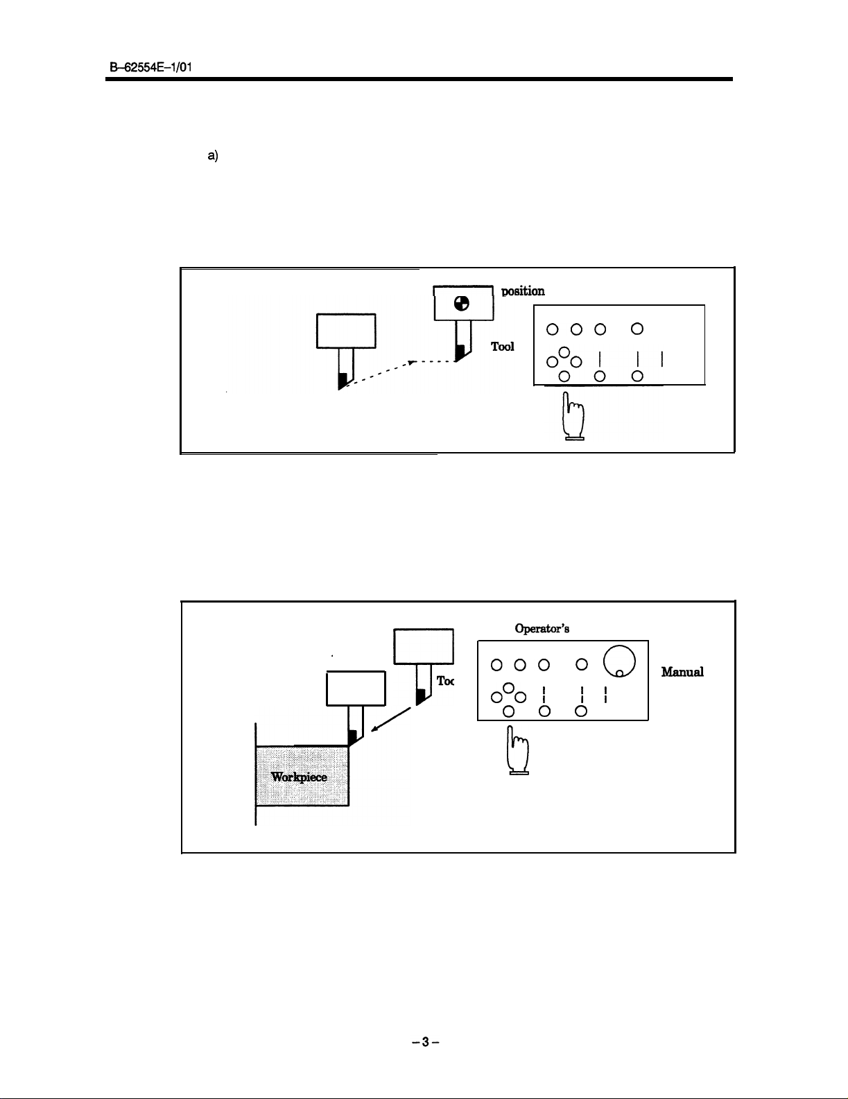
Manual reference position return (See Section 4.1)
a)
The memory in the CNC machine tool holds the positional data for setting the machine.
This position is called the reference position, where the tool is replaced or the coordinate are set.
narily, after the power is turned on, the tool is moved to the reference position.
Manual reference position return is to move the tool to the reference position using switches and push-
buttons located on the operator’s panel.
1.
INTRODUCTION
Ordi-
I1
Fig. 1 (a)
The tool can be moved to the reference position also with program commands.
This operation is called automatic reference position return. (See Section 7.1)
b) The tool movement by manual operation
Using operator’s panel switches, pushbuttons, or the manual handle, the tool can be moved along
each axis.
.
Manual Reference Position Return
Tool
7
Reference
msition
000
Operator’s
000
o”o
I
0 0 0
Operation panel
panel
0
8
1
I
0
Manual
handle
h
Fig. 1 (b) Tool Movement by Manual Operation
Page 13
1. INTRODUCTION
2)
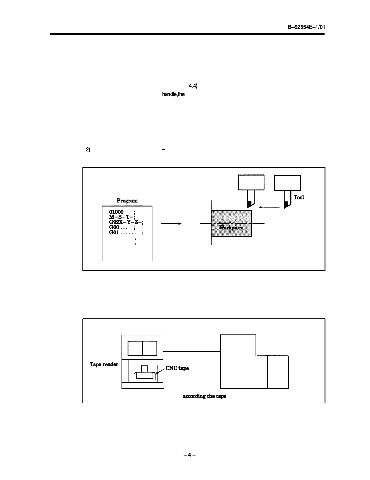
Tool movement by programing - Automatic operation (See Chapter 5)
B42554E401
The tool can be moved in the following ways:
i) Manual continuous feed (See Section 4.2)
The tool moves continuously while a pushbutton remains pressed.
ii) Step feed (See Section 4.3)
The tool moves by the predetermined distance each time a pushbutton is pressed.
iii) Manual handle feed (See Section
By rotating the manual handle,the tool moves by the distance corresponding to the
dle rotation.
iv) Manual feed at any angle
The tool is moved in any direction on the plane.
v) Manual numeric command
When numeric data is entered from the MDI keyboard, the tool is moved by the distance corresponding to the data
4.4)
degree of han-
.
Fig. 1 (c) Tool Movement by programing
Operating the machine according
are classified into operations according to tape, memory, and the MDI.
(i) Operation according to tape
I.
The machine can be
reader. This is called the operation according to
operated based on a program, while the program is being loaded from the tape
to a coded program is called automatic operation. Automatic operations
CNC
.CNCtqe
Operation accordingthetape
Machine
1
tape.
-r
Page 14

&-62554E-1 /Ol
1.
INTRODUCTION
(ii) Memory operation
After the program is once registered in memory of CNC, the machine can be run according to the pro-
gram instructions. This operation is called memory operation.
CNC
Memory
pr--w-w.
1
.
e-----4
(iii) MDI operation
After the program is entered, as an command group, from the MDI keyboard, the machine can be run
according to the program. This operation is called MDI operation.
I J-‘, .
I I
._--a
I
fi
’
I
Fig. 1
CNC
’
MDIGyboard
.
Manual
input
(d)
Memory operation
program
Machine
Machine
4
Fig. 1 (e)
MDI
Operation
Page 15
1. INTRODUCTION
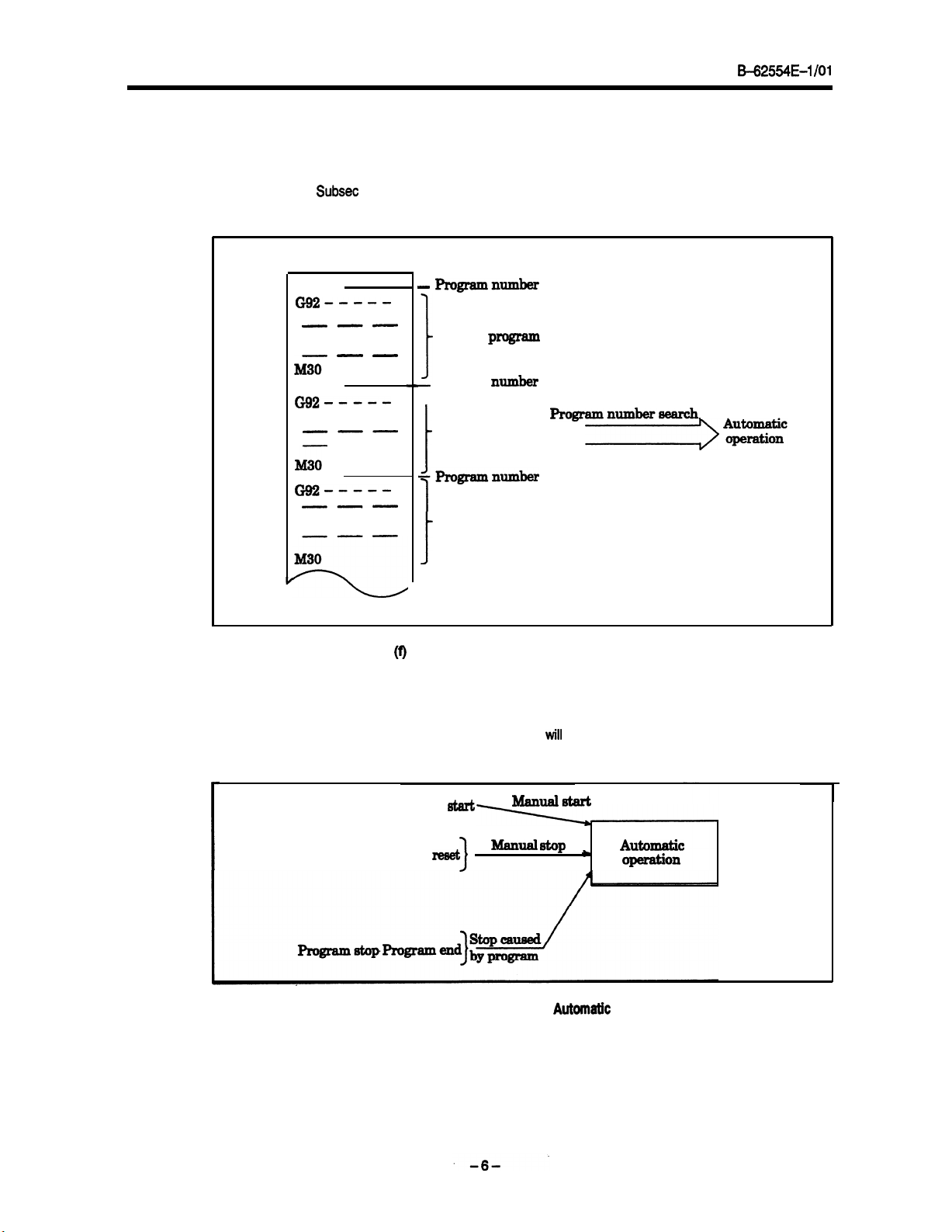
3) Automatic operation
(i) Program selection
B=62554E-1 /Ol
Select the program used for the workpiece. Ordinarily, one program is prepared for one workpiece.
If two or more programs are in memory, select
ber (See Subset 5.2.1).
-
01001
G92-_---
---
-v-
---
Programnumber
Work-l
the
program
program to be used, by searching the program num-
iii - -
01002
G92-___-
---
-m-
--
M30
01003
Gg2-__--
-m-
---
-w
M30
I
Fig. 1
(ii) Start and stop (See Section 5.3 to 5.5)
Pressing the cycle start pushbutton causes automatic operation to start.
or reset pushbutton, automatic operation pauses or stops. By specifying the program stop or program
termination command in the program, the
cess machining is completed, automatic operation stops.
]
Program
1
Work-2
t
+zqgramnumber
1
Work-3 program
i
(f)
Program
Cycle
program
Selection for Automatic Operation
start
Ilumber
running
ManualBtart
Progsramnumber8earch
By pressing the feed hold
will
stop during automatic operation. When one pro-
Feed hold
Fig. 1 (g)
Manual
reset
3
atop
Start and Stop for
Automtic
Autcomatic
apeFafion
Operation
Page 16
B-62554E-1 /Ol
1.
INTRODUCTION
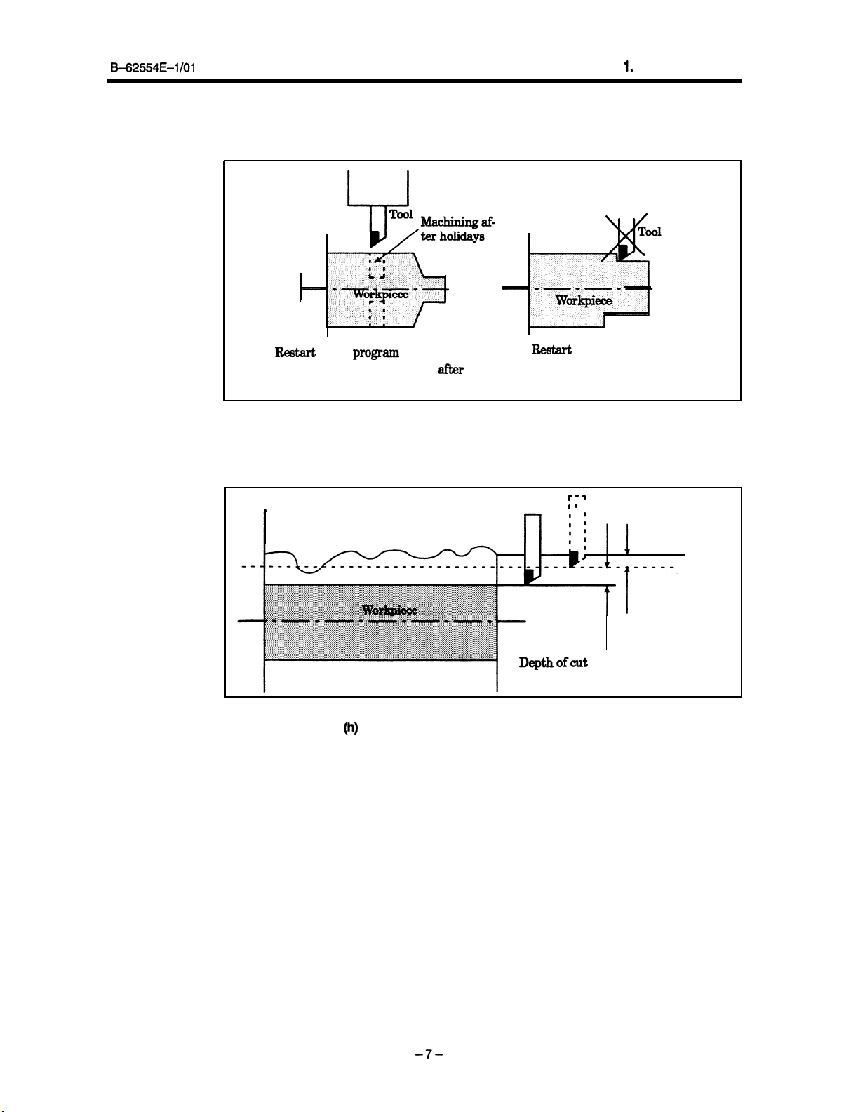
(iii) Restarting machining
Machining a workpiece can be stopped midway and restarted after several days’ holiday. Also, if the
tool is broken during machining, machining can be restarted after the tool is replaced.
Broken tool
Restart
Restart
of
the
progam
When machining is continued
afIx3r
of the block
When the tool is broken
holidays
(iv) Handle interruption (See Section 5.7)
While automatic operation is being executed, tool movement can overlap automatic operation by rotating the manual handle.
r-3
fi 0
.
Tool
Depth of cut specified
by the program
ofcut
by manual handle feed
Fig.
Depth
Handle Interruption for Automatic Operation
1
(h)
-f-
Page 17
1. INTRODUCTION
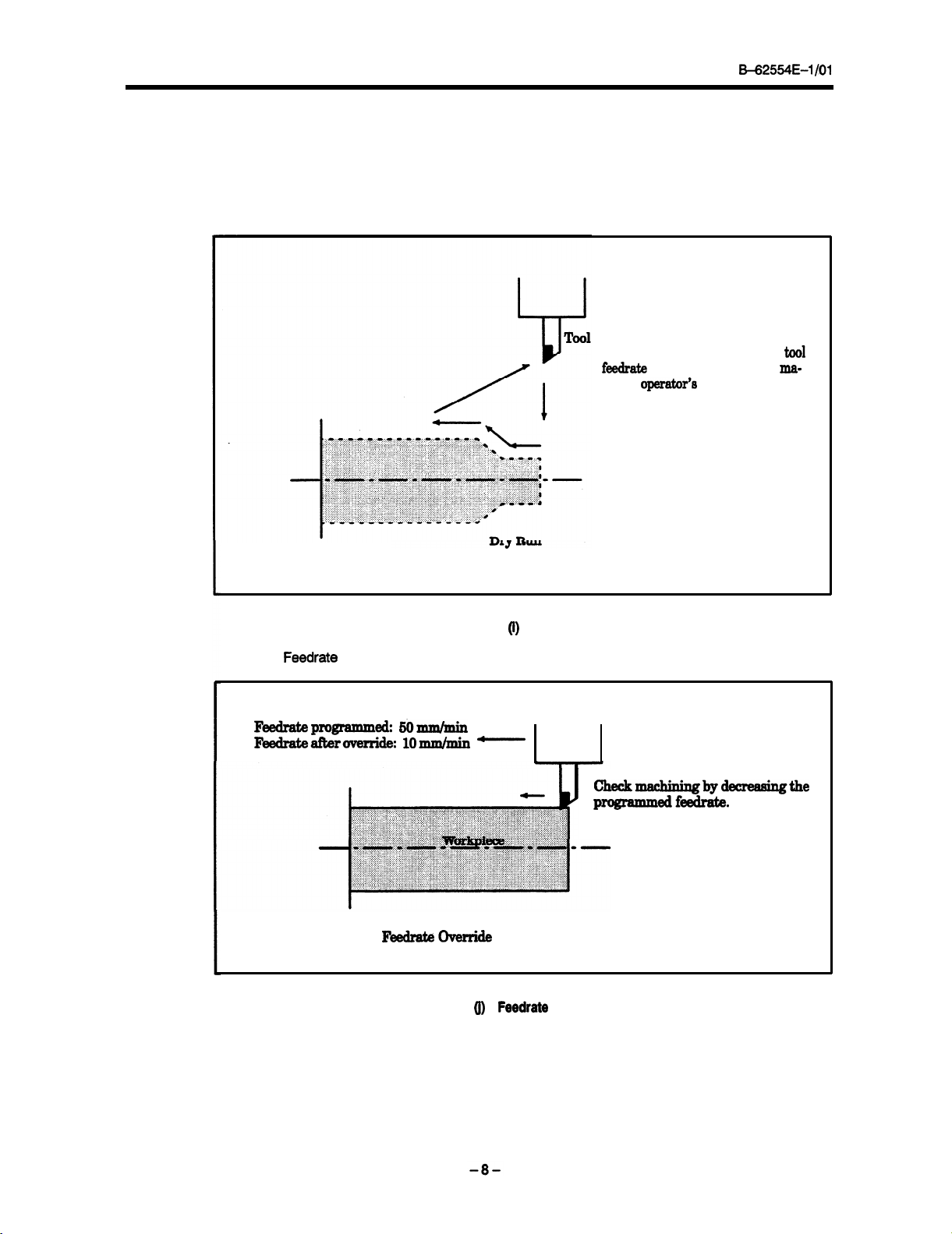
4) Program test (See Chapter 6)
Before machining is started, the automatic running check can be executed.
program can operate the machine as desired. This check can be accomplished by running the machine
actually or viewing the position display change (without running the machine).
a)
Check by running
i) Dry run (See Section 6.4)
B-62554E-1 /Ol
It checks whether the created
Remove the workpiece, and check
tool movement only Select a
f&ate
with the dial on the
chine
operator’s
panel
tool
ma-
Fig. 1
ii)
Feedrate
override
Feedrateprogramm& EiOm&nin
Feedrakeafberoverri~ 10mmhnin -
FbdrateWerride
Fig. 1 0,Feedtate
(i)
Dry Run
Override
Checkmbydecreaeingthe
programmedf-.
Page 18
B42554E-I/O1
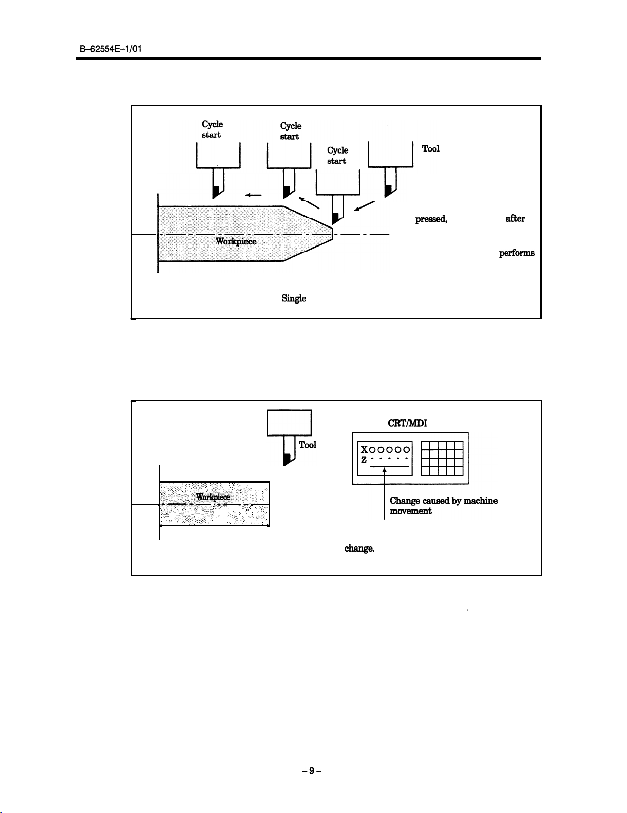
iii) Single block (See Section 6.5)
Singe Block
Fig. 1 (k) Single Block
1.
INTRODUCTION
When the CYCLE START button
is
pressed,
the tool stops
&r
performing one operation. When
the CYCLE START button is
pressed again, the tool
performs
another operation, then stops.
The program is checked in this
manner.
b)
How to view the position display change without running the machine
i) Machine lock (See Sections 6.1 and 6.2)
CRT/MD1
,_,_..: ., : ::
,:,:,: ..::..: .:,,:..: :._:::; :.I:
,:.I. Y:,,::_. ‘.. ,.,:,,_ ,. ,.‘f_:...
,,,, :.,. :::, ‘,: .. ‘.‘...
,,, .:...:.. ‘. ,. .,.:.::.
..::... .:... “.. ,,
::::.. ; ,.:.::.:,:. ..::::.::‘,.:‘:.::,:;
:::.
.I ::::,, ,,;: .: ,;,; ::;_ :.: ;:I .:.. :i,~&~~~.: ‘:::;i ; $ ,: .;
,I.: .:,,. ,. :.‘.‘.:.:, ,,,. .;:i:. .: : ... ,; .;:. .:. _,.
’ .“‘i:.::::@.
:.
._
., .‘,, 1.: :.:
_,_, ,:,__ : .,:,:, .:.I’
,:. .,.> .:. ..,._. :., ., .: ,.‘.‘. ‘.
_’,. ., . . .
,.:.:.,,
. .
.‘.:.O: ;
.
...,., .:: :i:.._.
. . . .
.,.
:.,;:
::..:..‘:.‘..’
:
,A._..‘. ‘.
“‘,” :.
‘,
.‘:‘, : .‘: .,:., .,;, :
I
:
,.:.:.. :. .,... .,.. :
:,
. .
,‘.‘,‘:‘,.:: .,.;,. 1.z.. “..,’
“. .,i..,:: .:,’
., ,, :. .:.,:
1.: .:.
.,. :... ‘: ., ‘.
‘.
. : : : _.I
.’ .“..., :,::,;:, ,,.,_.,. ,..‘. ._,,. .:.,
:.i:+::<
.
.,
:
“”
..;,& ::.:::::,i. ,,, .’ ‘.
.
.,... >.. Z.‘.‘, :, :.
.:‘: ,‘..‘. ..:
: ,.; :.,
,.
., _,
. : . .
:.‘:. ;.’ :.
._ ..,’ .:’ .;, :
.
1:;.
; :
I;.
,, ,.;.. ::
.*.*
I--
..‘. ,:‘.: .:
..,. ..; ..,.
:, ‘, : : ,..
.
‘_.:_’ ‘.,,‘,._,..
1: ,..
. .
\
The tool remains stopped, and
only the axis position indications
change.
Machine Lock
Fig. 1 (I) Machine Lock
ii) Auxiliary function lock (See Section 6.3)
.
When automatic running is placed into the auxiliary function lock mode during the machine lock
mode, all auxiliary functions (spindle rotation, tool replacement, coolant on/off, etc.) are disabled.
-9-
Page 19
1. INTRODUCTION
B=62554E-l/O1
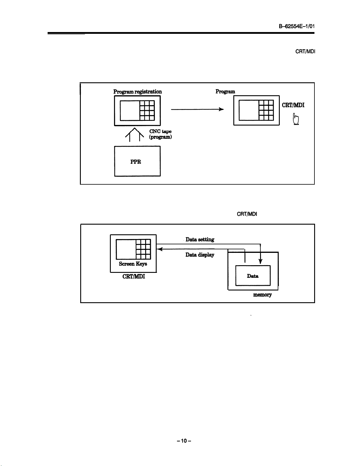
5) Part program editing (See Chapter
After a created program is once registered in memory, it can be corrected or modified from the
panel.
This operation can be executed using the part program storage/edit function.
Program
registmtion
9)
Progmm
correction or
modification
CRT/MIX
I
Fig. 1
(m)
Part
6)
Data display/setting (See Chapter
Data
stored in NC memory can be displayed and corrected via the
Program
IO)
Editing
CRT/MD1
screen.
CRT/MD1
1
!2
Fig. 1 (n) Data Display/Setting
-lO-
CNC
memory
,
Page 20
562554E-l/O1
1.
INTRODUCTION
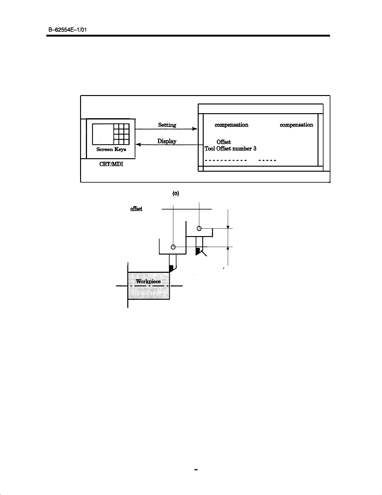
i) Offset value (See Section 10.1)
The tool has the tool dimension (length, diameter). When a workpiece is machined, the tool movement
route depends on the tool dimensions.
By setting tool dimension data in CNC memory beforehand, automatically generates tool routes that
permit any tool to cut the workpiece specified by the program.
value.
Geometric Wear
compexwation
Tool Offset number 1
Tool
Offeet
ToolOffbetnumber3 -----
-----------
----------I
I--
Tool
offset
value
setting
Display
Fig. 1
(0)
Offset Value Display/Setting
Tool dimension data is called the offset
mmpendion
number 2
CNC memory
12.3
20.0
----- -----
----I)
25.0
40.0
-----
-----
1r
I
I
Tool
Fig. 1 (p) Offset Value
JL
c
-11
-
Page 21
1. INTRODUCTION
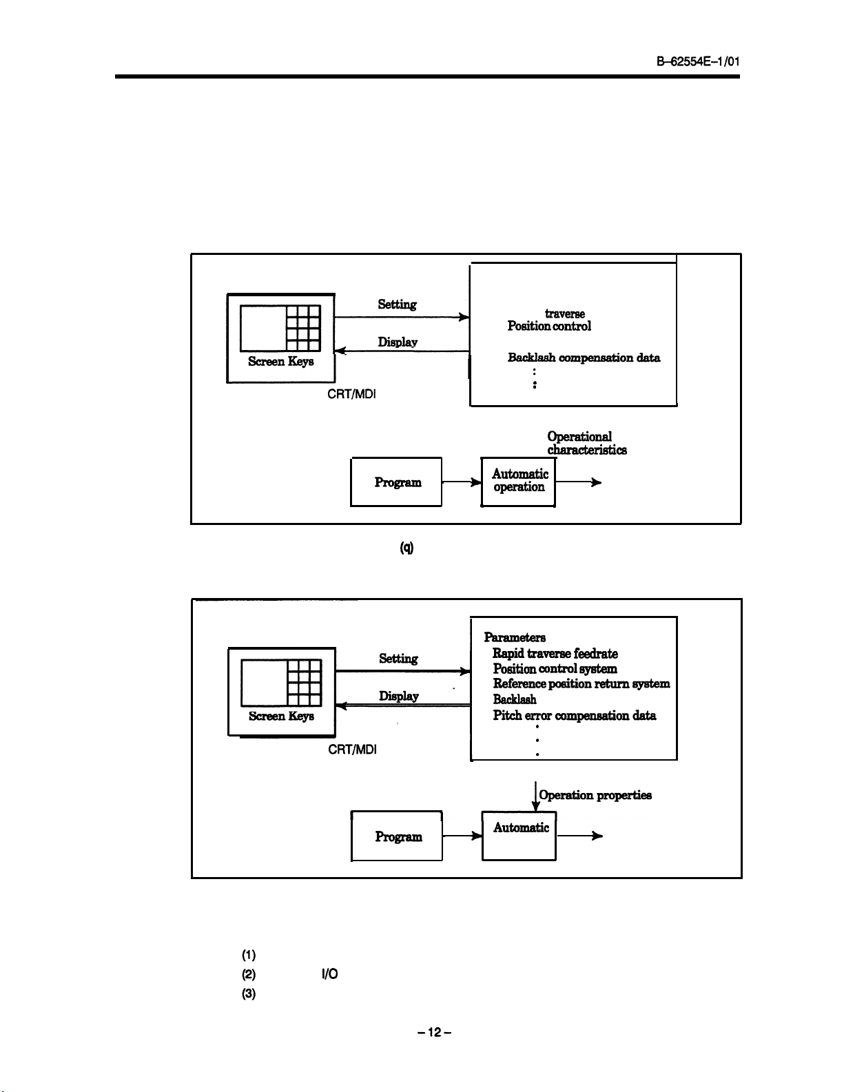
ii) Displaying and setting parameters (See Section 10.4)
H2554E-I /Ol
The CNC functions have versatility in order to take action in characteristics of various machines.
example, CNC can specify the following:
a) Rapid traverse rate of each axis
b) Whether the position is detected with digital or analog data
Whether reference position return is based on the grid or analog system
The data determining these items are called parameters (see Section 10.5).
The parameters are specific to the machine.
For
Parameter
Rapid
traverse
rate
Positioncontrol
I-
CRT/MD1
bfi!r=
Fig. 1
iii) Displaying and specifying data (see Section 10.3)
CRT/MD1
’
*
(cl)
Parameter Display/Setting
I
.
.
CNC
memory
operational
cthmacbMcf4
\
.
1
Automatic
operation
&
Machineoperation
.
Parameter8
Rapid&a- feedrate
Po8ition cOIltro1 system
Ref-nce position return 0y8tem
BacHash
PitcherraF~rnpensatioIldata
compensation data
.
.
.
CNC
memory
II
program
In addition to the parameters, settings for changing the attributes of the machine are provided. The
operator can set these items if necessary while the machine is operating..
For example, the following settings are provided:
Settings for the area the tool must not approach (stroke check)
Settings for
Amount of return and minimum depth of cut in the canned cycle
I/O
devices
-12-
’
b
operation
Automatic
b
Machine movement
Page 22
M2554E-I /Ol
1. INTRODUCTION
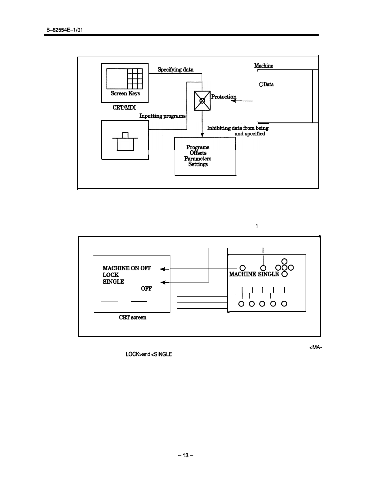
iv) Data protection key (See Section 10.8)
specifyingdata
1
J&chine
I
ScreenKeys
CRT/MD1
rnputtingpmgramB
1
I
Tape reader
Fig. 1 (r)
The protection key prevents the programs, offsets, parameters, and settings from being regis-
tered, changed, or deleted by mistake.
v) Menu switches and software operator’s panel (See Section 10.10 and I 0.12)
I
ollr3ets
Parameters
settings
CNC memory
Data Protection key
Pmtection
I
key
-
Signals
operator’s
r
I
OData
protection key
registered
panel
I
000
A
SINGLEi
I I I
0
0
I
MACHINEONOFF
LOCK
SINGLEi
BLOCK ON
OF’F
v
+
0
MA-
LOCK BLOCK
I I I I
-I I
00000
c
CRT screen
Turn on and off some of the switches provided for the machine operator’s panel
CHINE
LOCK>and ANGLE
BLOCK> switches on the CRT screen.
Machine
operator’s panel
such as
4MA-
Page 23
I.
INTRODUCTION
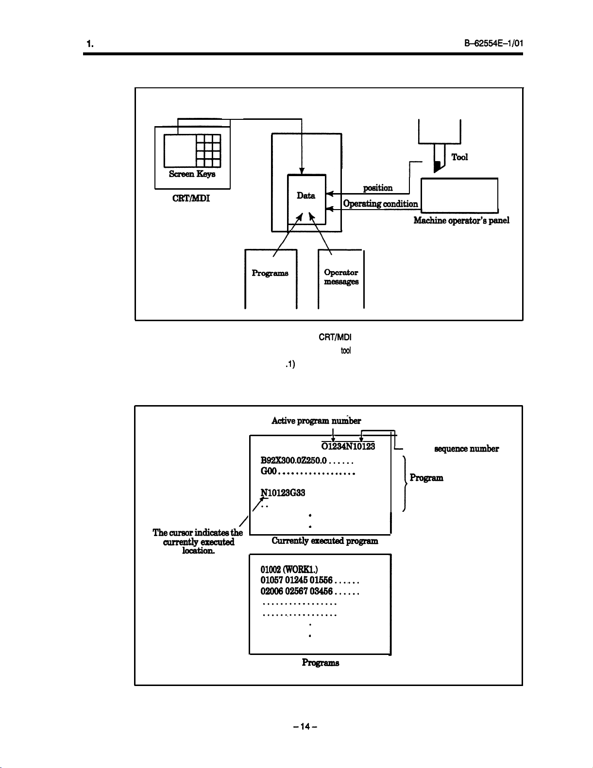
7) Display
Tool
p&ion
opelxdixlg CoxlditioIl
B=625!54E-1 /Ol
0
The contents of memory are displayed on the
The
memory contains information on
(i) Program display (See Section 11 A)
The contents of the currently active program are displayed.
and the program list are displayed.
Active program
CRT/MD1
programs,
tool
Ilkber
I
0
Ol234NlOl23
BQ2X300.02250.0......
. . . . . . . . . . . . . . . . . .
. . . . . . . . . . . . . . . . . .
GO1
Thecur8orindicate8the
/
currentlyexecuted
NlOl23G33
. . . . . . . . . . . . . . . . . . . . . . . . . . . .
/’
currentlyeaecutedpmgram
. . . . . . . . . . .
.
.
Machine
screen.
position, and
I
+
suchlike.
In addition, the programs scheduled next
-
Active
program
content
opeator’s
mquencenumber
I
panel
01002(w0RlKl.)
01046
010570l24501556.......
0200602S6703456......
.
-14-
Page 24
B-62554E-1
/Ol
1.
INTRODUCTION
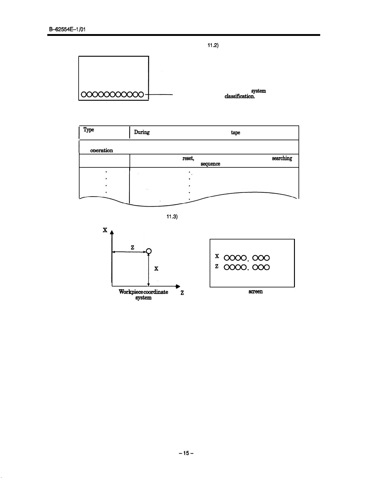
(ii) Displaying the state of the system (See Section
Displays the current state
CRT
screen
Type
of automatic
operation
I
Type of manual
oDeration
I
State of automatic When operation is
operation
(iii) Current position display (See
During
I
I
operation using memory,
During jog feed, handle feed, or incremental feed
11.3)
11.2)
of the
the
clawifkation.
MDI, or
tape
reset,
stopped, or suspended, or when
for a
6equence
number
system
accordingto
searching
x
f
CRT
Workpiececoordinate
system
The current position of the tool is displayed with the coordinate values.
position to the target position can also be displayed.
z
screen
The distance from the current
-1%
Page 25
1. INTRODUCTION
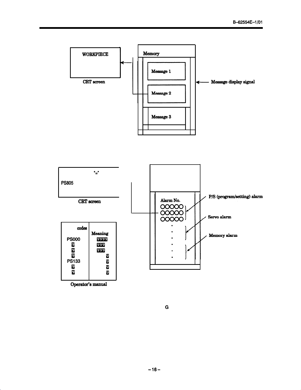
(iv) Displaying operator messages (See Section 11.4)
SET
(v) Displaying alarms (See Section 11.5)
B+2554E-1 /Ol
WORKPIEXE
When the system must notify the operator of necessary information during machining, the system dis-
plays the message preset in memory.
PSI33
MISSING
PS605
ILLEGAL COMMAND
CRTaxeen
Error
axles
Code
PSOOO
El
I
B
PS133
lzl
lzl
If a failure occurs while the machine is operating, the system displays the corresponding error code
and alarm message on the CRT screen.
For details of the error codes, see Appendix G in Operator’s Manual (Programming).
Y=w
t
-169
Page 26
B-62554E-1
/Ol
(Vi) Displaying the operating times
The system displays the following three operating times on the CRT
.
Value obtained by adding the automatic operating time
The system displays as follows the value obtained by adding the automatic operating time:
Example
10 hours 43 minutes 8 seconds
l
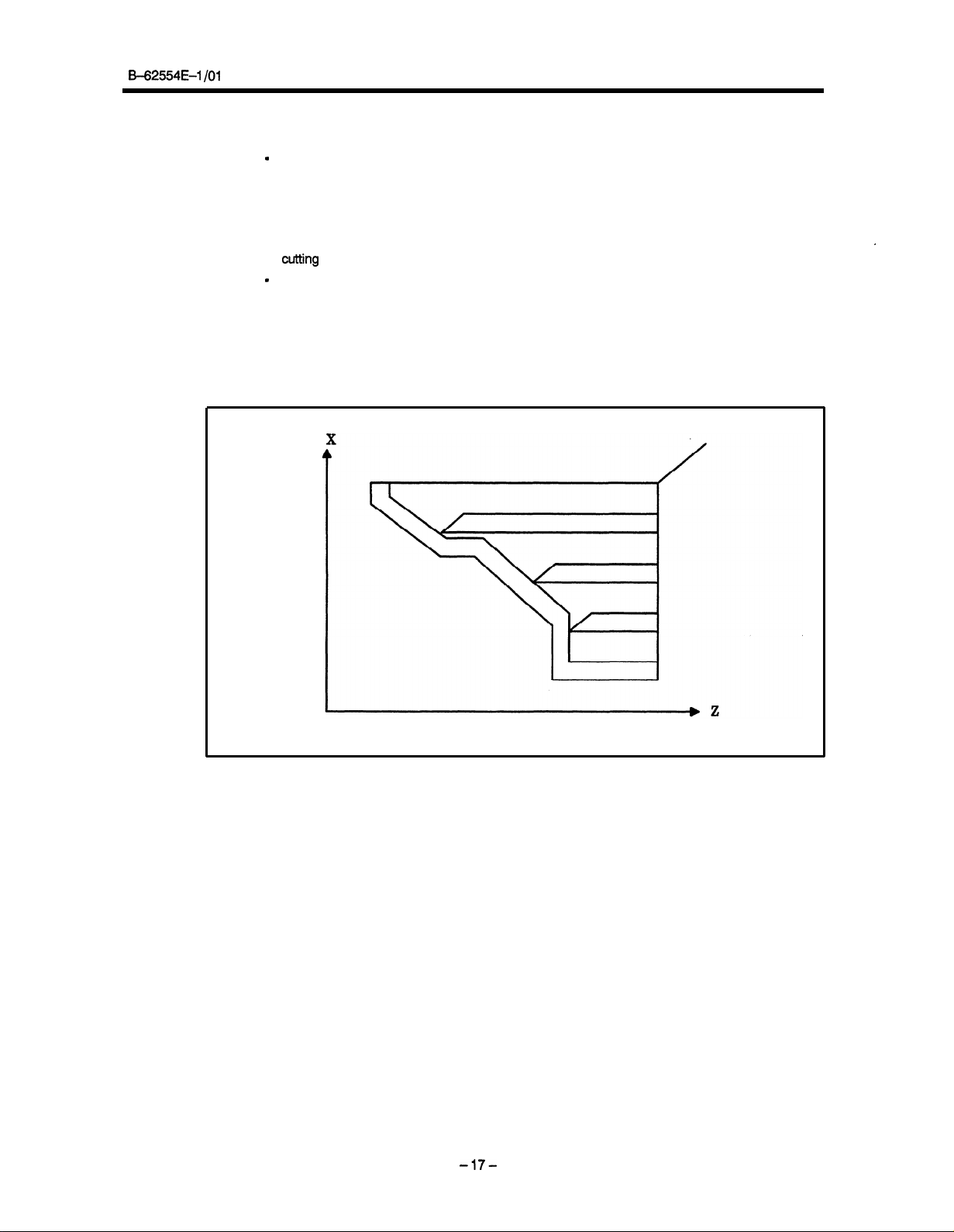
Value obtained by adding the cutting time
The system displays the value obtained by adding the time required for the machine to move by
cutting
feed (linear or circular interpolation).
.
General-purpose time display
The system adds and displays the elapsed time while the operating time count signal (an input
signal) is on. For the type of time displayed, refer to the manual issued by the machine tool builder.
These three types of operating times are displayed on the setting screen. For how to display data
on the setting screen, see Section 10.3.
(vii) Graphic display
1.
INTRODUCTION
.
-17-
Page 27
1. INTRODUCTION
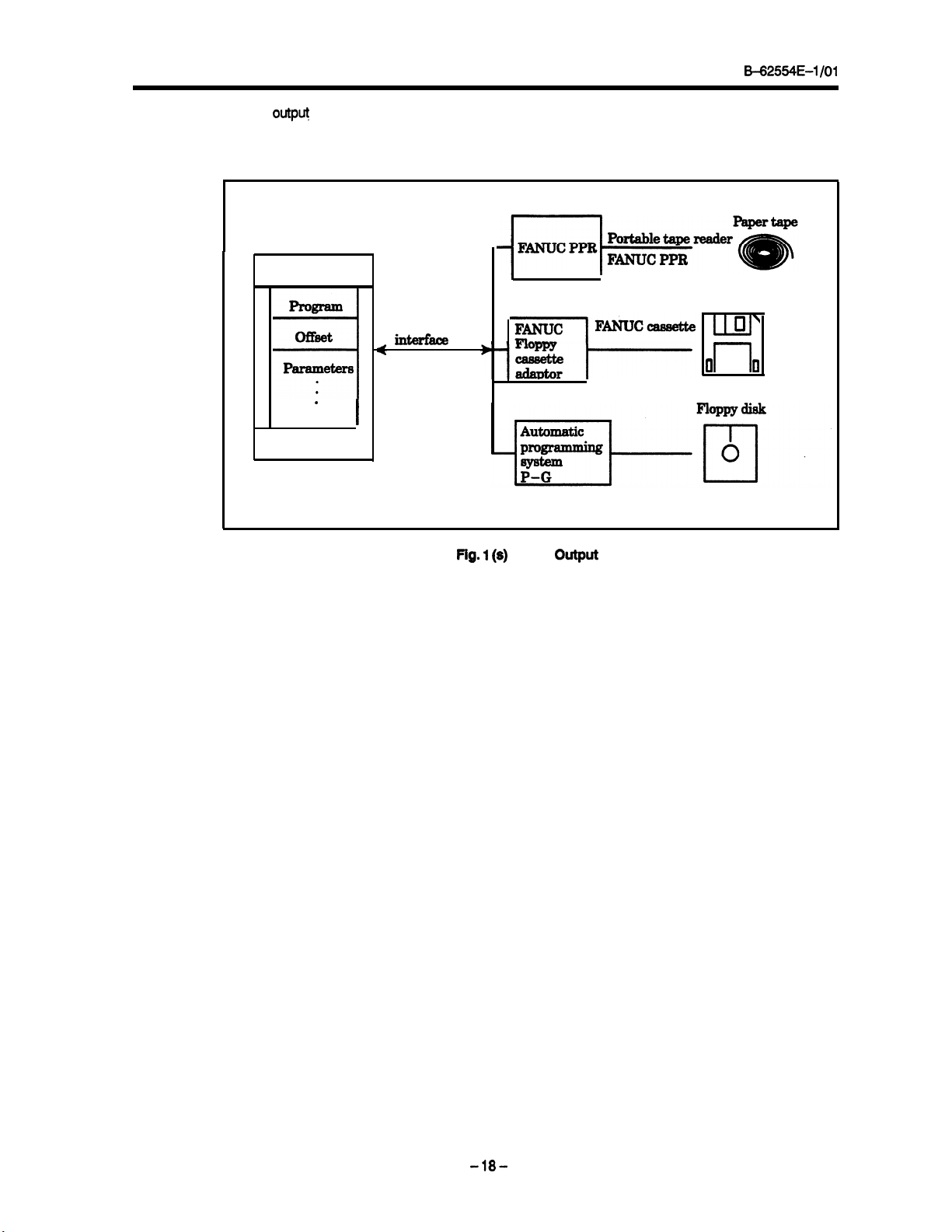
8) Data
Programs, offset values, parameters, etc. input in CNC memory can be output to paper tape, cassette,
or a floppy disk for saving. After once output to a medium, the data can be input into CNC memory.
output
(See Chapter 13)
Memory
B=62554E-1 /Ol
1
prograna
of&et
Parameters
.
.
4
.
CNC
Reader/puncher
iIlMB
I
Fig.
1
(s)
Data Output
LLU
0
rl
\
II
-18-
Page 28
B-62554~01 /Ol
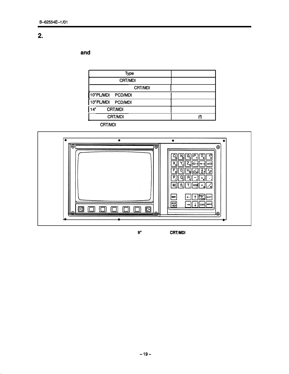
2.
OPERATIONAL DEVICES
2.1
Setting
Setting and display units are classified into the following types.:
and
Display Unit
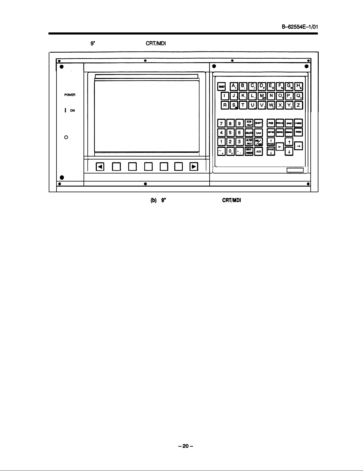
2. OPERATIONAL DEVICES
L
9” monochrome
9” color or monochrome
1 lo” PUMDI
110” PUMDI
114”
color
14” color
/
(a) 9” monochrome
or
or
CRT/MD1
CRT/MD1
CRT/MD1
Type
CRT/MD1
PCD/MDI
PCD/MDI
(Vertical)
(Horizontal)
(Small)
(Small)
CRT/MD1
(Vertical)
(Horizontal)
(Standard)
1
Remarks
Fig.
2.1
(a)
Fig. 2.1 (b)
Fig. 2.1 (c)
Fig. 2.1 (d)
Fig. 2.1 (e)
Fig. 2.1
(f)
Fig. 2.1
(a)9” monochrome
-19-
CRT/MD1
(Small)
Page 29
2. OPERATIONAL DEVICES
562554E-1 /Ol
PCMER
I
q
0
q
e
6
(b) 9” color or monochrome
ON
OFF
loooooool
CRT/MD1
6
Fig. 2.1
(Standard)
(b) 9”
color or monochrome
\
L
l
CRT/MD1
l
(Standard)
Q
El
El
J
0;
l
e
Page 30
B+2554E-1 /Ol
(c) IO”
PIJMDI
POWER
or
PCD/MDI
(Vertical)
2.
OPERATIONAL DEVICES
a
Fig.
2.1 (c)
IO” PlJMDI
or
PCD/MDl
(Vertical)
-21
-
Page 31

2.
OPERATIONAL DEVICES
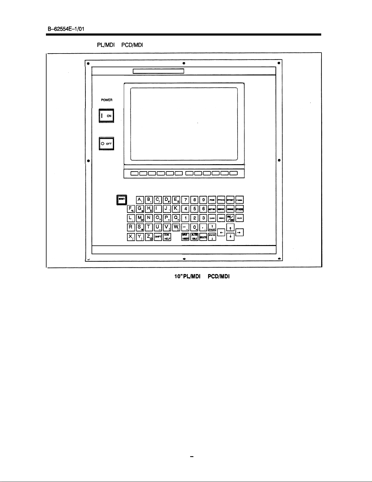
(d)
lO”PL/MDI
POWER
0
OFF
0
1
000000000000
or
PCD/MDI
(Horizontal)
B=62554E-1 /Ol
El
HH
Eiil
QQRliiil
1
Fig. 21
(d) 1O”PUlUDI
or
PCD/MDI
(Horizontal)
Page 32

B-625541=-1 101
(e)
14”color CRT/MD1
(Vertical)
2.
OPERATIONAL DEVICES
Fig. 2.1 (e)
14”color CRT/MD1
-23-
(Vertical)
Page 33

2. OPERATIONAL DEVICES
B-62554E-I /Ol
(f) 14”color CRT/MD1
1
000000000000
(Horizontal)
I
,
Fig. 2.1
0
(f) 14Volor
CFWMDI (Horizontal)
Page 34

B-62554E-l/O1
2.1.1
MDI
2. OPERATIONAL DEVICES
keyboard
POWER
(4)Function
)POWERon/offbuttons
menu key
e
(3)soft
keye
(2)RESET
(6)Opaation menu key
(6)Numerical keys
key
(6)Address
b
key
(oDlPwr/
-w t(13)m
(23)OTHERS key
(lS)P-CHECK key
q
change
key8
(24)EOB/HELP
key
(14)PMCYCNC
key
Page 35

2. OPERATIONAL DEVICES
B=62554E-1 /Ol
No.
(1)
<Power>
<RESET> key
(2)
(3) Soft key
(4)
Function menu key
Table 21.1
Name
ON/OFF button Press this button to turn CNC power ON and OFF
Press this key to reset the CNC, to cancel an alarm, etc.
The soft key has various functions, according to the Ap-
plications. The soft key functions are displayed at the
bottom of the CRT screen.
Pressing this key
selection keys (see Subsection 2.1.8) returns the soft
keys to the states of the function selection keys.
ing the key when the soft keys are function selection
keys changes the soft keys
that do not fit on the screen. (The 9”
five soft keys. The
However,
plications. In this case, a plus sign (+) is displayed at the
extreme right of the bottom line on the CRT The plus
sign indicates that some soft keys do
MDl
Keyboard
when the soft
these soft
14”
functions
Functions
to
CRT/MD1
keys are not sufficient for some ap-
(l/3)
keys are not function
the function selection keys
CRT/MD1
panel has ten soft keys.
not fit on the
screen.)
(5)
Operation menu key The functions of the soft keys vary according to the ap-
(6) Address/numerical key
(7)
<SHIFT> key
(8)
<INPUT/INSERT>
(9) ALTER key
key
plications. Pressing this key when the soft keys are not
operation selection keys changes the soft keys to the
operation selection keys that are effective on the selected CRT screen (see Subsection 2.1 .l 0).
this key when the soft keys are operation selection keys
changes the soft keys to the operation selection keys
that do not fit on the screen. (The 9”
five soft keys. The
However, these soft keys are not
plications. In this case, a plus sign (+) is displayed in the
rightmost frame of the bottom line on the CRT. The plus
sign indicates that some soft keys do not fit on the
screen.)
Press these keys to input alphabetic, numeric, and other
characters.
Some address keys are marked with two characters. To
enter the lower right character, press the shift key first.
When the shift key is pressed, A is displayed in the key
input buffer. This indicates that pressing the address key
enters the
I, *I $,
These characters can be used on the MMC screen.
When an address or numeric key is pressed, the data is
entered in the key input
CRT Press the input key to store the data entered in the
key input buffer in the offset register.
The input key is equivalent to an
ther may be used.
Pressing this key on the program editing screen inserts
the contents of the key input buffer after the position
where the cursor is located. The INSERT soft key has
the equivalent function. Either key can be used.
Pressing this key on the program editing screen replaces
the word where the cursor is located with the contents of
the key input buffer. The ALTER soft key has the equivalent function. Either key can be used.
,lower
\I -9 <, % :, ;, %
14”
CRT/MD1
c
right character.
’
buffer,
CRT/MD1
panel has ten soft keys.
sufficient
then displayed on the
<INPUT>
for some ap-
soft key.
Press-
panel has
Pressing
panel has
Ei-
.
-260
Page 36

B-62554E-1
/Ol
v
No.
(10) DELETE key
(11) Cancel
(12) Cursor move keys
(I 3)
Page change keys
(14)
PMC/CNC
(15) MMC key
(16) POS key
(17) PROG key
Name
<CAN>
switch key
key
2. OPERATIONAL DEVICES
MDI
Table 21.1
Pressing this key on the program editing screen deletes
’
the word where the cursor is located. The DELETE
WORD soft key has the equivalent function. Either key
can be used.
Pressing this key deletes a character or symbol input to
the key input buffer.
The contents of the buffer are displayed on the CRT The
position where a new entry is to be input is displayed with
an underscore
letes the character immediately before the underscore.
Example) When the contents of the key input buffer are
displayed as shown below,
>NOOI
Xl OOZ
pressing the
tents change as follows:
>NOOl
The following four cursor keys are provided:
--,
:
This key moves the cursor
ments.
The cursor is moved in the direction of order.
+
:
This key moves the cursor
ments.
The cursor is moved to the opposite direction.
4
:
This key moves the cursor for the key input buffer
forward when a character is entered in the key input buff-
er. The position of the cursor for the key input buffer is
indicated by an underscore. Pressing an address or nu-
meric key enters an address or number at the cursor
position. Pressing the cancel
character before the cursor position.
This key moves the cursor on the CRT
large increments when no data is entered in the key input
buffer.
The cursor is moved in the direction of order.
7
:
This cursor key moves the cursor for the key input
buffer backward. This key moves the cursor on the CRT
screen backward in large increments when no data is
entered in the key input buffer.
The cursor is moved to the opposite direction.
Two kinds of page change keys
c11x
CRT screen in the forward direction.
<
t
CRT
screen in
The small 9” monochrome
vided with page keys. Pressing the
keys simultaneously is equivalent to pressing the
page key. Pressing the c- and I’ cursor keys simultaneously is equivalent to pressing the t page key.
This key is used to determine whether the
el is used for the CNC or PMC.
Pressing this key enables the
MMC. This key is valid only when a CNC having the
MMC is used.
Pressing this key selects the current position display
screen. The POSITION soft key has the equivalent function. Either key can be used.
Pressing this key selects the part program display
screen. The PROGRAM soft key has the equivalent
function. Either key can be used.
Keyboard functions
Functions
(J.
Pressing the
CAN
key deletes Z and the displayed con-
Zl 00
This key is used to changeover the page on the
x
This key is used to changeover the page on the
the reverse direction.
CRT/MD1
(2/3)
CAN
(cancel) key de-
forward
backward
<CAN>
CRT/MD1
in small incre-
key deletes the
screen
are
described below.
panel is not pro-
--,
and 4 cursor
to be used in the
in small incre-
CRT/MD1
forward in
J1
pan-
-270
Page 37

2. OPERATIONAL DEVICES
B42554E-1 /Ol
No.
1
OFFSET key
P-CHECK key
WV
SETTING key
m
SERVICE key
(21)
MESSAGE key
(23
(23) OTHERS key
(24) HELP key
(SHlFT/EOB)
Arithmetic
(25)
<SHIFT>+<ATER>
(26) 1
<AlJX>
Name
<CALC>
key
Table 21.1
I
Pressing this key selects the tool’offset display screen or
the screen displaying offset from the workpiece reference
position. The OFFSET soft key has the equivalent func-
tion. Either key can be used.
Pressing this key selects the program check screen. The
P CHECK soft key has the equivalent function.
key can be used.
Pressing this key selects the setting screen. The SET-
TING soft key has the equivalent function. Either key
CanbeuSed.
Pressing this key selects the parameter and diagnosis
screen. The MAINTENANCE soft key has the equivalent
function. Either key can be used.
Pressing this key selects the screen for alarm messages
and operator messages. The MESSAGE soft key has
the equivalent function. Either key can be used.
Pressing this key selects and displays the screen speci-
fied with parameter No.
Pressing this key displays the help window on a screen.
Alarm help, soft key help, and G code guide can be dis-
played. For details, see Help Functions.
Press this key to execute operation commands in the key
key
input buffer.
Example) When the data in the key input buffer is
20 x 30 +
the data in the key input buffer is changed to 660.
The arithmetic key is standard.
1
Auxiliary key
MDI
Keyboard functions
Functions
2215.
400/8],
the arithmetic key is pressed. Then,
(3/3)
Either
[lo
+
-280
Page 38

&-62554E-1
2.1.2
2.1.3
/Ol
2. OPERATIONAL DEVICES
Contents to be displayed and operations when the MMC is installed
The data to be displayed and key input operations vary entirely according to whether the MMC screen or CNC/
PMC screen is displayed on the
The MMC switch key and
PMC screen is displayed.
When the
cal to those for the Series 15-MB.
This manual describes the contents displayed and the operations when the CNC screen is selected.
to the machine tool builder’s manual for the contents displayed and the operations when the MMC screen is
selected.
(1) Selecting the MMC screen
(2) Selecting the
CNC/PMC
Press the MMC switch key to select the MMC screen.
Press the
screen
played displays the CNC screen.
Press the
CNC or PMC screen) before pressing the MMC switch key.
screen is selected, the contents displayed on the
CNC/PMC
CNC/PMC
is displayed displays the PMC screen.
CNC/PMC
key while the MMC screen is displayed to change the display mode (to display the
CRT/MD1
CNC/PMC
screen
key to display the
panel.
switch key are used to determine whether the MMC screen or the
CNC/PMC
Pressing the
screen.
CRT/MD1
Pressing the
CNC/PMC
key while the PMC screen is dis-
CNC/
and the operations are identi-
Refer
CNC/PMC
key while the
CNC
Changing the contents of the key input buffer
Inserting characters
(1)
The contents of the key input buffer are displayed on the CRT. When the next address or numeric key is
pressed, the corresponding character is inserted at the cursor position indicated by an underscore.
the +- or
Move the cursor to the desired position, then enter the desired characters.
Example
To enter
@ Press the
@ Enter 690 by pressing the corresponding address and numeric keys.
@ Press the
Deleting characters
(2)
Move the cursor to the position after the characters to be deleted, then press the
key is pressed in the shift
Example
To delete
@ Press the -+ cursor key to move the cursor to the desired position:
@ Press the
@ Press the
t-e
cursor key to move the cursor.
Contents of the key input
GQO
after NO01 in this case, perform the following:
+--,
cursor key to move the cursor to the desired position:
>NOOl
Xl OO.OY2OO.OF1OO.O;
>NOOl
GQO Xl OO.OY2OO.OF1OO.O;
&-
cursor key to move the cursor to the following position:
>NOOl GQOXI
>NOOl
>NOOl
>NOOl
OO.OY2OO.OF1OO.O;
state,
all data in the key input buffer is deleted.
Contents of the key input buffer displayed:
Y200.0,
perform the following:
Xl
OO.OY200.0 FlOO.0;
<CAN>
key five times.
Xl 00.0
Xl
FlOO.0;
+-Ccursor
OO.OF100.0;
key to move the cursor to the following position:
buffer
-
displayed:
>NOOl
Xl
OO.OY2OO.OFl
>NOOl Xl OO.OY2OO.OF1
OO.O;_
<CAN>
OO.O;_
key.
If the
Press
<CAN>
.
2.1.4
Warning message
Data must be input in the specified format.
in the key input buffer in order to execute some operations, a warning message is displayed.
The warning message is displayed in highlighted characters in the line above the key input buffer field.
characters are displayed at higher intensity on the 9” monochrome CRT or in purple on the 14” color CRT.
When a warning message is displayed, the soft keys function as cancel keys. When the cancel key (soft key)
is pressed, the warning message is canceled.
fied format. Then, the operations specified by the data can be executed again.
2.1.5
Soft key display
The 9”
CRT/MD1
the five soft keys on the 9”
panel has five soft keys. The 14”
.
CRT/MD1
If an attempt is made to input data that violates the specified format
Change
panel. The soft keys are displayed as follows:
the
format of the data in the key input buffer to the speci-
CRT/MD1
panel has ten soft keys. This manual describes
The
Page 39

2.OPERATlONALDEVlCES
B-62554E-1
/Ol
b
POSITION PROGRAM
OFFSE'f PRG-CHK CHAPTER
/
+
The plus sign in the rightmost frame indicates that there are other soft keys that do not fit on the CRT
The same basic method for operating soft keys applies to both the 14”
the 9”
CRT/MD1
panel with five soft keys.
Obviously, it is not necessary to scroll the soft keys on the 14” CRT/
CRT/MD1
panel with ten soft keys and
MDI panel.
When some soft keys for setting operations or operation guidance are pressed, processing is executed immediately. These keys are underlined on the screen.
1
EXEC
t
Underlined soft keys are displayed at higher intensity on the 9” monochrome CRT They are displayed in green
on the 14” color CRT
Some soft keys are displayed in parentheses on the screen.
When these soft keys are pressed, a message prompting the operator to enter the corresponding data is dis-
played.
When the soft keys are Insufficient
2.1.6
As
mentioned above, the 9”
equipped with ten. These soft keys may be insufficient for some applications. When the soft keys are used
as function selection keys, for example, up to seven functions can be selected.
is displayed in the rightmost frame of the bottom line on the 9”
(1) When the soft keys are used as function selection keys
When
the
function
of the bottom line, the soft keys change to the function selection keys that do not fit on the screen.
(2) When the soft keys are used as operation selection keys
When the operation menu key (rightmost key) is pressed while the plus sign is displayed in the rightmost
frame of the bottom line, the soft keys change to the operation selection keys that do not fit on the screen.
(3) When the soft keys are used as chapter selection keys
When the chapter selection menu key (soft key) is pressed
frame of the bottom line, the soft keys change to the chapter selection keys that do not fit
CRT/MD1
panel is equipped with five soft keys and the
14” CRT/MD1
In this case, the plus sign (+)
CRT/MD1
CRT
menu key (leftmost key) is pressedwhilethe plus sign is displayed in the rightmost frame
while the
plus sign is displayed in the rightmost
on the screen.
panel is
-3o-
Page 40

B-62554E-1 /Ol
2.1.7
The soft keys are used as either function selection keys, chapter selection keys, operation selection keys, or
operation guidance keys.
The procedure for changing the function of the soft keys is tis follows:
2. OPERATIONAL DEVICES
Changing soft keys
(1) Changing the soft keys to the function selection keys
Pressing the leftmost function menu key changes the soft keys to the function selection keys.
(2) Changing the soft keys to the chapter selection keys
a
Selecting chapters in the function selection key state
( 1
The currently selected function key is displayed at higher intensity on the 9”
on the 14”
sequence.
Changing the soft keys from the function selection keys to the chapter selection keys
(b)
Pressing the
tion keys to the chapter selection keys. Select the desired chapter by pressing the soft keys. To return
the soft keys to the function selection keys, press the function menu key. To return the soft keys to
the operation selection keys, press the operation menu key.
C
Selecting chapters in the operation selection key state
0
To enable chapter selection when the soft keys are used as operation selection keys, use the soft keys
as both the operation selection keys and the chapter selection keys. To switch between these modes,
press the operation menu key. Pressing the chapter selection keys selects new chapters. To return
the soft keys to the operation selection keys, press the operation menu key.
(3) Changing the soft keys to the operation selection keys
(a) Pressing the rightmost operation menu key changes the soft keys to the operation selection keys in
whichever state the soft keys may be.
(b) Entering data in the key input buffer when the soft keys are used as the function selection keys is as-
sumed to be an attempt by the operator to execute an operation.
change to the operation selection keys.
(4) Changing the soft keys to the operation guidance keys
(a) Changing the
Press the operation selection key.
The following block diagram (Fig2.1.7) shows how to change the soft keys through their various
modes.
CRT/MD1
panel. Whenever the function key is pressed, new chapters can be selected in
<CHAPTER>
s@t
soft key (rightmost soft key) changes the soft keys from the function
keys from the operation selection keys to the operation guide keys
CRT/MD1
The soft keys then automatically
panel or in green
selec-
-31.
Page 41

2. OPERATIONAL DEVICES
B=62554E-I/O1
bww~w--w-----J
-w
Function menu key
~---r~-----rJ
.
r---~---r.w-rr---r-~
i kxt
operation selection key
~-~~-r-rrr~~~--~r-r-J
T
Operationmenukey
t
4
Not empty
Function
:
BelectioIl
4
Key
key
.l
input
I
Operationkey
cbapterselection
@oft
hnction menu key
.
I
Operation menu key
J
I
I
v
key)
v ‘I
.
I
.
Fig.
21.7
Changing method of
-320
*
softkey
Page 42

B-62554&1 /Ol
2.1.8 Outline of operations
Select the data to be displayed and the major item to be entered on the
selection key (soft key).
Each major item is divided into minor items (called chapters). Select a chapter with the chapter selection
soft key.
To perform a certain operation such as data input, select the operation with the operation selection soft key.
Pressing the operation selection key changes the soft key to the operation guide key. The executable operations can be checked with the operation guidance key.
Pressing some operation guidance keys immediately executes the corresponding operation. However,
pressing other operation guidance keys displays a prompt for the operator to enter the data required for
starting the corresponding operation.
Operation guidance keys that immediately execute an operation are displayed in higher intensity on the
9” monochrome CRT or in green on the
displayed in blue-green.
When operation guidance keys that displays a prompt for the operator to enter the required data is pressed,
if the address that corresponds to the data has been determined, the system automatically enters the address into the key-input buffer. Otherwise, the operator determines the address and inputs the data.
When the necessary data is entered in the key input buffer, the soft key changes to the EXEC key which
starts execution.
Press the EXEC key after the necessary data is entered in the key input buffer. The corresponding opera-
tion is then performed.
14”
color CRT
2.
OPERATIONAL DEVICES
CRT/MD1
Operation guidance keys that display a prompt are
panel with the function
2.1.9 Function selection keys
Both soft keys and the keys on the MDI panel (hard keys) can be used to select a function. When using the
soft keys to select a function, first press the function selection menu key to display the function selection soft
keys, then press the corresponding function selection soft key.
You can also select a function by pressing the corresponding hard key on the MDI panel.
Functions can be selected in any mode.
Detailed function selection is performed with the chapter selection soft keys.
The following function selection keys are provided:
(Soft key)
POSITION PROGRAM
SETTING SERVICE MESSAGE CHAPTER +
(Hard key)
POS PROG OFFSET P CHECK SETTING SERVICE MESSAGE OTHERS
IIIIIIL-IInn
(1)
[POSITION] soft key or
Press this key to select the current-position screen.
(2) [PROGRAM] soft key or
Press this key to select the part-program screen.
.
OFFSET
<PO&
<PROG>
PRG-CHK CHAPTER +
4
\
hard key
hard key
-330
Page 43

2. OPERATIONAL DEVICES
B=62554E-l/O1
[OFFSET] soft key or
Press this key to select the tool offset screen or the screen for the offset from the workpiece reference point.
[PRG-CHK] soft key or <P-CHECK> hard key
Press this key to select the program check screen.
[SETTING] soft key or
Press this key to select the setting screen.
[SERVICE] soft key or
Press this key to select the parameter or diagnosis screen.
[MESSAGE] soft key or <MESSAGE> hard key
Press this key to select the alarm or operator message screen.
OTHERS
Press this key to display the screen for a function other than those described in steps (1) to
a graphics screen. Parameter No. 2275 is used to assign a function to this soft key.
2.1.10
Chapter selection keys
The function selection keys are used to select major items. Each major item is divided into minor items called
chapters. The chapter selection keys are used to select the chapters.
To select a chapter, change the soft keys to
key.
(1) Chapter selection keys on the position screen
The chapter selection keys on the position screen are as follows:
<OFFSET>
<SETTING>
<SERVICE>
hard key
hard key
hard key
the
chapter selection keys, then press the desired chapter selection
(select<POSITION>function
key)
(7),
such as
OVERALL
(a) [OVERALL] key
Press this key to select the overall-position screen on the position screen.
(b)
[RELATIV]
Press this key to select the relative-position screen on the position screen.
(c)
WSOLLCTJ
Press this key to select the screen for the positions in the workpiece coordinate system on the position
screen.
(d)
[MACHINEI
Press this key to select the screen for the positions in the machine coordinate system on the position
screen.
(2) Program chapter selection keys
The program chapter selection keys are as follows:
Press this key to select the program text screen.
(b) [DIR.MEM] key
Press this key to select the screen for the programs stored in the program memory (directory).
screen displays the program numbers, program names, and other information.
RELATIV ABSOLUT
key
key
key
(select<PROGRAM>function
MACHINE
.
key)
This
-34-
Page 44

B-62554E-1
/Ol
2. OPERATIONAL DEVICES
(3) Offset chapter selection keys
(selectcOFFSET>function
key)
The offset chapter selection keys are as follows:
GEOM.
WRKZER
(a) WEAR] key, [GEOM.] key
Press this key to select the tool offset screen.
(b) wRK.ZER] key
Press this key to select the screen for the offset from the workpiece reference point.
(4)
Command-value chapter selection keys (select <PRG-CHK> function key)
The command-value chapter selection keys are as follows:
\
LAST
BUFFER3
a
LAST
( 1
Press this key to select the screen for displaying the command value of the block immediately preceding the block being executed, and the coritinuous-state values of the G codes, F codes, etc. specified
before that block.
ACTIVE key
(b)
Press this key to select the screen for displaying the command value of the block being executed, and
the continuous-state values of the G codes, F codes, etc. specified before that block.
C
NEXT key
(
1
Press this key to select the screen for displaying the command value of the block immediately following
the block being executed, and the continuous-state values of the G codes, F codes, etc. specified
before that block.
BUFFER1 key
(4
Press this key to select the screen for displaying the command value of the block that is two blocks
ahead of the block being executed, and the continuous-state values of the G codes, F codes, etc.
specified before that block.
e
BUFFER2 key
(
1
Press this key to select the screen for displaying the command value of the block that is three blocks
ahead of the block being executed, and the continuous-state values of the G codes, F codes, etc.
specified before that block.
BUFFER3 key
Press this key to select the screen for displaying the command value of the block that is four blocks
ahead of the block being exe&ted, and the continuous-state values of the G codes, F codes, etc.
specified before that block.
(5) Setting chapter selection keys (select
The setting chapter selection keys are as follows:
key
ACTIVE
NEXT BUFFER1
,
&ElTING9unction
BUFFER2 +
key)
I
.
1
+
HANDY
GENERAL
OPPWL
.
MACRO
-35-
Page 45

2. OPERATIONAL DEVICES
(a)
[HANDY]
Press this key to select the input-output setting screen.
(b)
[GENERAL]
Press this key to select the screen for the parameters that can be set.
(c)
[OP.PANEL]
Press this key to select the menu switch or software operator panel screen.
(d) [MACRO] key
Press this key to select the custom macro variable screen.
(6) Service chapter selection keys (select &ERVICE>function key)
B=62554E-1 /Ol
key
key
key
,
PARAhd
PITCH
Press this key to select the parameter screen.
(b)
FlTCHJ key
Press this key to select the pitch error compensation data screen.
(c)
[DIAGNOS]
key
Press this key
(d)
[DSPMEM] key
Press this key to select the screen displaying
Message chapter selection keys (select
0
The message chapter selection keys are as follows:
DIAGNOS DSP-
to
select the diagnosis screen.
<MESSAGE>
ALARM 0PEIuwoR
c
Press this key to select the alarm message screen.
(b)
[OPERATOR]
Press
key
this key to select the operator message screen.
I
.
the
contents of the memory for CNC control software.
function key)
2.1.11 Operation selection keys
The possible operations vary according to the screens selected with function selection keys or chapter selection keys. To improve operability, only the names of the operations enabled on the displayed screen are displayed
in the field
To select an operation, change the soft keys to the operation selection keys, then press the desired operation
selection key.
For the operations of the operation selection keys, refer to the individual descriptions.
for the operation selection (soft) keys.
Page 46

E62554E-l/O1
2. OPERATIONAL
DEVlCES
NOTE
(1) When no data is entered in the key input buffer
When the operation selection key is pressed while no data is entered in the key input
buffer, the soft keys change to the operation guidance keys. The operation guidance keys are used to display information about the current operation or the possible operations.
Enter the necessary data in the key input buff&.
tion key is pressed, the corresponding operation is performed. This procedure reduces the number of times keys are pressed when the operator understands the
operation without using the operation guidance keys.
Some operations cannot be performed unless the operation guidance keys are
used.
This section describes how to use the operation guidance keys.
Example
INPUT
(a) Pressing the INPUT key changes the soft keys to the operation guidance keys.
Setting offsets
Operation selection keys:
+INPUT
ORIGIN COUNTER
When the desired operation selec-
INENO.
+
(b) Pressing the (VALUE) key displays the message prompting the operator to enter the offset data.
(c) Entering the offset data changes the soft keys as follows:
,
EXEX
L
(d)
(2) When the offset data is entered in the key input buffer
(a) Pressing the INPUT key stores the data of the key input buffer in the memory corresponding to the
L
Pressing the EXEC key stores the data of the key input buffer in the memory corresponding to the offset number at the cursor.
offset number at the cursor.
_
2.1 .I 2 Operation guidance keys
The possible operations vary according to the which operation selection keys are pressed. To improve oper-
ability, only the possible operations corresponding to the pressed operation selection key are displayed using
the corresponding operation guidance keys (soft keys).
Pressing some operation guidance keys immediately starts the corresponding operation while pressing others
displays a prompt for the operator to enter the necessary data.
Operation guidance keys that immediately execute an operation are displayed in higher intensity on the 9”
monochrome CRT or in green on the
In this manual, these soft keys are underlined.
Entering data using the keys changes the soft keys as follows, irrespective of whether the operation guidance
keys are pressed:
14”
color CRT
EXEC
I
Pressing the EXEC key executes the operation specified for the data in the key input buffer.
For the use of the operation guidance keys, refer to the individual descriptions.
-3?-
Page 47

2. OPERATIONAL DEVICES
B=62554E-I
/Ol
2.1.13
Changing language of the display
The
language
of the CRT display is specified with a parameter. The following languages are available:
Japanese, English, German, French, Italian, Spanish, and Swedish.
$mTIfficm+mY)
Tuaew
izfKs
Imn DWIOE
WTPur DRJIdE =
Ibwr DEwa
QlTpuf
REGLt7ismmJIA~
WIF Tu
alEPEw
WIT ENTE
DISP D’m
CpFlEIL SomIE =
DIP
-IL -1E
mEMaE
D’m
= a ce:oFF
= 0
ce: Is0
= 8 ce:Im
=
2
c1-3:Rs232c
1e:m-w
2
Cl-3:v
= 3
-86.EDIF
= 3
-B&EDIT-
English
= 1 <o:f#R
= 8 m
= 0 CwJrl
= 2
2
= 3 -86.EDIT-
= 3
IS0
Cl-3:RS23X
10: Rm-BLJF
c1-3:Rq232c
-BG.EbIT-
-IN88888
l:mo
1:EIAB
T: 1NcH~
13:
Rs422)
13:
RS422)
-1-
l:wR>
l:EIta
1:PoucE)
13:Rs422)
13:
Rs422)
REGUAZCSEPFLf~
WRIF
TV
amrc Ewe
!&iFiF
B
mcrtCl
DIP
I-
m
WclTa =
CERtF 7U
Cdbreb PBRF
DIS, WIm
=
a
C&D&IN l:INS>
= 8 cm Iso
=
8
ce:m
=
2
Cl-3:Rs232c
10: FFtT_BLF
= 2
cl~3:Rs232c
= 3
-HxDIT-
3
-ffiEDIT-
Italian
=
#
ce:Imc lrcm
= 0
(0: Iso
=
2
Cl-3:s
10: RM7-BUF
=
2
Cl-3:Rs232c
= 3
+DI-No FM*
=
3
-EDI-No
-1N88888
1:EIAJ
1:mLLIcE)
13:
Rs422)
13:Rs4221
1:EIW
1:Pum
13:
Rs422)
13:
Rs422)
PRIO-
French
INS1
LLCEWER)
= 1
= 8
IH#rmw.
IbmT. um
lJm?muTRsr
Mm. lm
lJlt5-=
ld)I 0.8 m 8888 888 .8+ 11:12:=
= 8
=
2
18:RllT-Bc 13:R922)
= 2
=
3-BRAED3-BRAED-
-I-
ce:w
1:P
C0:ISO l:EICI)
ce:ml
Cl-3:CZSZEC
Cl-3:-
Swedish
1
l:M)
13:‘R%22~
a
OIPt’llR+
Spanish
-38-
Page 48

B_62554E-1 /Ol
2.1
.I4
Arithmetic key (SHIFT or ALTER key)
The arithmetic key is a standard key and is used to evaluate the arithmetic expressions in the key input buffer
whose data is entered from the
2. OPERATIONAL DEVICES
MDI
panel.
(1) Operation
@)
Enter data from the MDI panel.
@ Press the CALC key.
@
The expression is evaluated, and
the result is stored in the key input
buffer.
(2) Arithmetic expressions
Enter the arithmetic expression in the same way as a general one.
0
An alphabetic or special character string other than a function
as the end code of an arithmetic expression.
sions to be entered in the key input buffer. The CALC key evaluates of each expression.
Example
Example 2
(3)
Types of numeric values
This function uses integers and real numeric values.
(a) Input format
Example 10735
Example
(b) Internal data format
(c) Types of values obtained by calculation
.I
100.0/2;200.0/2;300.0/2_
4
50.0;1 00.0;150.0_
X350.0~Y120.0/5;X20.0lk
4
Xl
05O.OY24.O;X70.0_
Integers: Strings of numbers from 0 to
Real values
Integers
Real values :
i) A calculation involving integers and real values produces a real value.
ii) The result of a calculation is converted into a character string in the following range, then stored
in the key input buffer:
Integer : -99999999 to 99999999
Real value :
:
Strings of numbers containing a decimal point
IO.23
:
One-bit sign and 31-hit binary data
MQE
M:
One-bit sign and 31-hit binary data
E :One-bit sign and seven-bit binary data
-99999999.0 to
,*O
,.00000001
3.5_
-.0000001
to 99999999.0
100.0
+lO.O_
CALC
I
llO.O_
name in the key input buffer is regarded
The
use of some end codes enables multiple expres-
9
-39-
Page 49

Page 50

B-62554E-1 /Ol
2.
.
<multiplication or division operator>: The following characters are used to indicate multiplication and
division, respectively:
*
and (blank)
<unsigned integer>: <numeric character> string
<numeric character> . . .
Example) 4567
<fraction part>: <numeric character> string
<numeric character> . . .
Example)
<unsigned integer>:
<function name
<function name
<enclosed expression>: <expression> enclosed in square brackets
<simple factor>: <unsigned number> and <enclosed expression>
<function call>: The following two types can be used:
<factor>: <simple factor> and <function
<item>:
<expression>:
I>:
2>:
Example) <unsigned number>: 12.34
Example) <enclosed expression>: [I 0.1 +
i) Calling <function name
ii) Calling <function name
Example) <simple factor>: [I .O + 2.5 * 3.3331
Example) <function call>:
<factor>
and multiplication or division between <item> and
<factor> and <item><multiplication or division
Example) <factor>:
Example)
<item> with <sign> and addition or subtraction between <expression> and
{<sign>)<item> and <expression><addition
Example)
Example)
EXP[2.0]
. . .
A decimal point is inserted between <unsigned integer> and
<fractional part>.
{<unsigned
Example) 101.02
The following character strings are used to represent the functions of sine, cosine,
tangent, square root, absolute value, inverse cosine, inverse sine, natural
logarithm, and exponent of e:
SIN, CON, TAN,
The following character string is used to represent the inverse tangent function:
ATAN
The format is
the function of <function name 1~ for <enclosed expression>.
The format is <function name 2> followed by two <enclosed expression> units to
execute the function of
expression> units.
<function name 1
expression><enclosed
Example)
Example)
<item>cmultiplication
integer>}.{<fractional
SQRT,
[<expression>]
&r&on
SIN[30.0]
ATAN[2.5] [5.0]
ATAN[2.5] [5.0]
{<sign><item>:
<expression><addition
name 1~ followed by <enclosed expression> to execute
><enclosed
expression>
call>.
SQRT[3.0 * 2.01
or division
-2.2 * 5.1
ABC, ACOS,
1~
2>
<function
expression> and <function name
or subtraction
,
part>}
ASIN,
3.31
name 2> for two divisional <enclosed
operator><factor>
operator><facton:
Of
OPERATIONAL DEVICES
LN, and EXP
[ ]
2><enclosed
<factor>
12.3 SIN[l .I *
subtraction operator><item>
operator><item>:
3.01
-1.2 3.0 +
<item>
.
-41
-
Page 51

2. OPERATIONAL DEVICES
2.2 Machine Operator’s Panel
B-62554E-1
/Ol
The
operator’s panel varies in functioning and switch arrangement between th8
a typical
.
the machine tool builder.
Op8ratOr’S pan81
mm! zN&
are explained as
DKYBUN
shown Fig. 2.2.
tiow8v8r,
for
details, refer
Fig. 22(a) An illustration for Operator’s panel
different tools.
Operations of
to the manual issued by
MANUALPULSEGENEItATOR
6lNGIZBLOCK DBPRUN
JOG&xN~
. .
. . .
. .
.
.
Fig.
Fig. 22(b)
PO6ITIONBEPUBN
Operator’s Panel (for
,420
Ais Lathe)
HANDLE
Page 52

B=62554E-1 /Ol
Function
CYCLE START button
FEED HOLD button
Mode selector
RAPID button
JOG & INCREMENTAL
buttons
Handle
SINGLE BLOCK switch
OPTIONAL BLOCK SKIP
switch
DRY RUN switch
REFERENCE RETURN
switch.
RAPID TRAVERSE
OVERRIDE selector
INCREMENTAL
selector
EMERGENCY STOP
button
LOCK MODE selector
MANUAL/ABSOLUTE
switch
FEEDRATE
dial
JOG
HANDLE AXIS selector
HANDLE
selector
OVERRIDE This dial specifies the override when the feedrate is
.
FEEDRATE
dial This dial specifies the continuous manual feedrate.
MULTIPUER
2. OPERATIONAL DEVICES
Table 2.2 Functions on the Operator Panel
Description
To start automatic operation, select an executable program
and press this button. The lamp indicating automatic
operation is on during automatic operation.
To decelerate and stop the tool, press this button during
automatic operation.
To select the mode according to the type of job, use this
selector.
To move the tool at the rapid traverse feedrate, press this
button.
To
carry
out continuous manual feed or incremental feed,
press these buttons.
To move the tool in the desired direction, rotate the handle.
To perform automatic operation in units of blocks, turn
this switch on.
To skip optional blocks, turn this switch on.
To perform a dry run, turn this switch on.
To return the machine to the reference position, turn this
switch on.
To apply rapid traverse override to the machine, select the
desired override.
To select the distance to be traveled per step during
incremental
Press this button when the machine must be stopped
immediately.
To select the display lock or machine lock mode, use this
selector.
This switch specifies whether the distance to be traveled
during manual operation is stored in the abusoiute register
when the operator manually intervenes in the automatic
mode.
overridden during automatic or manual operation.
This selector is used to select the axis along which the
machine is moved manually with the handle.
This selector is used to select the multiplying factor of the
distance traveled per graduation during manual handle feed.
feed,
use this selector.
/
7
Page 53

2.
OPERATIONAL
2.3 Tape Reader
The tape readers are classified into three types:
(1) Tape reader without reels
(2) Tape reader with reels
(3) Portable tape reader
2.3.1
Tape reader without reels
1) Names and descriptions of each section
DEVICES
B=62554E-1 /Ol
comp&ment
Fig. 2.3.1 (a)
Table 23.1 Descriptions for each part
Name
tight Sources
Optical Reader
Capstan Roller
Tape Reader Control Switch
@ TapeBox
.Names
of Each Section
Functions
each channel and for the feed hole
in total). A built-in Stop Shoe functions to
decelerate the tape. The light source is attracted to the optical reader by a magnet so
that the tape will be held in the correct position. This unit can be opened upward, by
tuning the tape reader control switch to the
RELEASE
net).
Reads data punched on the tape, through a
glass window. Dust or scratches on the
glass window can result in reading errors.
Keep this window clean.
Controls the feeding of tape as specifyed by
the control unit.
A
3-posiion
Reader.
RELEASE
AUTO
MANUAL
A Tape Box is located below the Tape
Reader. A belt used to draw out a paper
tapeis
taoe
position (this turns off the mag-
switch used to control the Tape
.a.
The tape is allowed to be
free, or used to open the light
source.
When loading or unloading
the tape, this position is se
lected.
...
The tape is set to fixed posi
tion
by
theStop
feed and
stop of the tape is controlled
operation or data input from
tape, the tight Source must
be dosed and this position
must be selected.
The tape can be fed in the
...
forward reading direction. if
another position is selected,
the tape feed is stopped.
located inside the box. The paper
can easilv be Dulled out using this belt.
(9diodes
Shoe. The
Page 54

&-62554E-1
/Ol
2) Tape reader handling
a) Tape loading
@ Open the front door of the tape reader.
@ Set the Tape Reader switch to the RELEASE position.
@ Lift the Light Source Unit, and insert an NC tape between the gap. The tape must be posi-
tioned
@
Pull the tape until the top of the tape goes past the Capstan roller.
@ Check
@ Lower the Light Source.
0
Turn the switch to the AUTO position.
@J
Suspend the top and rear-end of the tape in the Tape Box.
.
b) Unloading the NC tape
@)
Open the front door of the tape reader.
@ Turn the switch to the RELEASE position.
@ lift the Light Source and remove the tape.
@ Lower the Light Source.
@ Close the front door of the tape reader.
2.
as
shown in the figure, when viewed looking downward.
1
Direction
that
the NC tape is correctly positioned by the Tape Guide.
of tape
f&ding
OPERATIONAL DEVICES
3
Feed hole
m
Page 55

2.
OPERATIONAL DEVICES
&62554E-1 /Ol
2.3.2 Tape reader
(1) Names and description of each section
6.
Red
with
reels
Llight-
/
/
6. Reelboom
Thebeltispulleduptodraw
/
out the CNC tape.
Fig. 23.2 (a) Names of Each Section
-
Belt for
drawing
fhepapertape
out
Page 56

B=62554E-1 /Ol
2. OPERATIONAL DEVICES
Table 2.3.2 (a) Descriptions of Each Section
No. Section
I
Light source
2
Optical reader
Capstan This roller serves as a tape feeder and operates according to
3
4
Reel
Reel boss This boss is used to accept the reel. The boss rotates the reel
5
Tension arm This arm adjusts the tension of the tape fed from the reel. The
6
7
Control switch This switch changes the operating modes of the tape reader.
8
AUTO lamp This lamp comes on while the tape reader is automatically op-
Description
Nine
LEDs
tion. A built-in stop shoe stops the tape. The section is attached to the optical reader with a magnet so that it also serves
as a tape retainer. The light source can be opened upward
when the control switch is turned to the RELEASE position
deactivate the magnet.
This section reads the tape and has a glass window.
dow is dirty or is damaged, a reading error may occur. The
window must always be kept clean and free from defects.
the command from the control unit.
This reel is used for fast-forwarding and rewinding the tape. A
150 m tape can be used.
and is driven by the reel motor according to the command from
the control unit.
arm absorbs the time delay in the tape transport when the reel
motor starts and stops.
The switch can be turn to one of the following positions:
RELEASE: Releases the tape so that it is free to move. The
light source can be opened upward. Before loading or unloading the tape, turn the switch to this position.
REEL ON: Secures the tape with the stop shoe and activates
the reel motor.
on the reel, turn the switch to this position.
REEL OFF: Secures the tape with the stop shoe, but does not
activate the reel motor.
the tape not on the reel, turn the switch to this position.
er, the reels must be used to rewind the tape.
When entering data from the tape by running it, be sure to close
the light source and turn the switch to the REEL ON or OFF
position.
erated by the control unit. When the lamp is on, the manual
operation buttons of the tape reader such as FORWARD
STOP
for channels and feed holes are installed in this sec-
Before operating the tape reader with the tape
Before operating the tape reader with
(ll),
and REWIND (12) are ineffective.
If the win-
Howev-
(lo),
-470
Page 57

2.
OPERAYTIONAL
DEVICES
B--62554E-1 /Ol
No. Section
ALARM
9
lamp
Table 2.3.2
(a)
Descriptions of Each Section
Description
This lamp comes on when an
When the lamp lights, eliminate the cause of the alarm and
turn the operation switch to the RELEASE position or press
the RESET button on the
goes off.
The following table lists the causes of alarms and the correspond-
ing lamp states.
\
No. Lights
1
-
2 AlARM FORWARD
3
Flashes Cause
ALARM
STOP
alarm occurs in
CRT/MDI
Reel operation error
1. When the control
2. When the operation
Tape reading error
1.
The brightness ratio is
2. Holes are punched in-
Tape
end
The tape has reached the
end.
(contitnued)
the tape reader.
panel. The lamp then
switch is at the REEL
ON position, the tape
has reached the end
or has become loose.
switch is at the REEL
OFF position, the re-
els are being used.
’
not adjusted correctly.
correctly.
1
The tape does not stop
at the EOR when it
4
REWIND
is rewound.
1. Defective stop magnet
2. Tape reading error
Page 58

562554E-1 /Ol
2. OPERATIONAL DEVICES
No. Section
Table 2.3.2
Description
l
No. tights
5
6
(a) Descriptions of Each Section (Continued)
Flashes
Cause
Data is read in the reverse direc-
tion when the control switch
is at the REEL OFF position.
1. During automatic opera-
-
ALARM
REWIND
tion
The rewind command or
the command for reading in the reverse direction is issued.
2. During manual operation
The REWIND switch is
pressed.
Serial data error
1. The baud rate is not
correct.
ALARM
FORWARC
STOP
REWIND
The stop bit is not
rect.
3. The host does not
stop transmitting data
when CS is either off or
cor-
2.
in the DC3 reception state. (The PTR
buffer is full.)
10
FORWARD button
STOP button
11
AUTO
ALARM
7
FORWARC
1. Watchdog
_
2. Abnormal power
STOP
REWIND
This button is used to feed the tape in the tape reading direction, i.e., forward. To feed the tape
fonrvard,
press the FORWARD button when the AUTO lamp is off and when the control
switch is at the REEL ON or REEL OFF position. When the
button is pressed, the tape continues to be fed until it stops
under one of the following conditions:
(i) When the STOP button is pressed
(ii) When ER (EIA code) or % (IS0 code) is read
(iii) When the RESET button is pressed on the
CRT/MD1
panel
This button stops the tape that is currently being fed with the
FORWARD (10) or REWIND (12) button.
-49-
Page 59

2. OPERATIONAL DEVICES
Table
2.3.2
(a) Descriptions of Each Section (Continued)
B-62554E-1
/Ol
No. Section
12 REWIND button
13
Tape compartment
Description
This button feeds the tape at high speed in the opposite direc-
tion to the reading direction.
lamp is off and when the operation switch is
position. When the
fed until it
If the REWIND button is pressed when the control switch is at the
The tape compartment is installed at the bottom of the tape
reader. The
the tape compartment.
be easily drawn out of the tape box.
stops
(i) When the STOP button (11)
(ii)
When an ER (EIA code) or % (IS0 code) is read
(iii) When the RESET button is pressed on the
el
REEL ON position, an alarm occurs. This is because the tape
cannot be rewound without reels.
button is pressed, the tape continues to be
under one of the following conditions:
bett
for drawing out the paper tape is installed in
Press this button when the AUTO
is pressed
Pulling up the belt enables the tape to
at the
REEL ON
CRT/MD1
pan-
Page 60

B=62554E-1 /Ol
2. OPERATIONAL DEVICES
(2)
Operation
(a) When no reels are used
The procedure for operating a tape reader with the reels removed is the same as that for operating
the tape reader with no reels.
(b) When reels are used
(i) Setting the tape
@ Set the tape in the reel.
However,
I
turn
the control switch to the REEL OFF position in step
(i)
Twist
the reel in the directions of the
arrows.
Then, the reel is
separated.
1
II II
@.
Hub
-51 -
(iii)Setthetapeinthereel.
(iv)
Twist
the reel in the directions of the
armwssothatthereeiandtapearefas-
tened,
Page 61

2. OPERATIONAL DEVICES
@J
Open the front door of the tape reader
@
Turn the control switch to the RELEASE position.
@
Mountthe
-
when
The right reel must be positioned so that the tape is fed in the counterclockwise direction as
shown below:
@
Draw the tape out of the reel.
reel
containing
facing the front of the tape reader.
the tape on the right reel boss and an empty reel on the left reel boss
&-62554E-1
/Ol
@
Feed the tape around tape guide A.
0
Feed the tape over the tension arm.
-520
Page 62

B-62554E-l/01
2. OPERATIONAL DEVICES
@ Insert the tape under tape guides B. The tape is easy to insert if it is held taut.
.
@
Check that
f-ii
Tape guide
the tape passes under rear tape guide C as shown below:
B
Tape guide C
.
‘Tap guide
@ Feed
0
the tape at the left side in
Wind the drawn tape leader onto the left reel and firmly roll the tape
so
that the tape
is
secured to the reel.
the same way as for the right side.
onto the reel several turns
C
-530
Page 63

2.
OPEFUK’lONAL
DEVICES
@ Check that the tape is set as shown below when it is viewed from the top.
If the tape is not set as shown in the figure above, the orientation of the reel on the boss is
reversed.
@ Make sure that the tape is correctly set along the tape guides.
@ Close the light source to hold the tape.
@ Turn the control switch to the REEL ON position. The reel then rotates a
arm moves to tension the tape.
reel.
If the left-hand reel is loose, repeat the procedure from step 0. If the right-hand reel
is loose, repeat the procedure from step
is stopped, the reel is not firmly secured to the reel boss.
from step
@ Close the front door of the tape reader.
(ii) Removing the tape
@)
Open the front door of the tape reader.
@ Press the REWIND button to rewind the tape.
tered, the tape stops.
When rewinding the tape is completed, press the STOP button to stop rewinding.
@ Turn the control switch to the RELEASE position.
@ Remove the reel from the boss.
@ Close the front door of the tape reader.
@.
In this case, press the REWIND button again to rewindthe whole tape.
If the reel continues to rotate, the tape is not secured to the
If the reel boss continues to turn when the reel
@.
In this case, repeat the procedure
If ER (EIA code) or % (IS0 code) is encoun-
&62554E-1 /Ol
little, and the tension
Page 64

B_62554E-1 /Ol
2.3.3 Portable tape reader
(1)
Names and descriptions of each section
2. OPERATIONAL DEVICES
Fig. 2.3.3 (a) Names of Each Section
Table 2.3.3 (a) Description of Each Section
12.
Photoamplifier
r
No.
1
Light
2
Optical reader
3
Capstan
4
Control switch
5
Tape compartment
6
Metal A
Section
source
Description
See the corresponding descriptions of the tape reader without reels.
1
Can contain a 15 m tape.
-55-
When
removingthe
internal
diameter
rolled
tape,
by
pushing the fastener.
reduce
the
Page 65

2. OPERATIONAL
DEVfCES
B=62554E-1 /Ol
Table 2.3.3 (a)
No.
7
8
9
10
11
12
13
(2) Operation
The operating procedure is the same as that for the tape reader without reels.
Preparations for using the tape reader and how to store the
(a) Preparations
@ Unlock the cover locks (9).
@ Take out the signal and power cables from the cable storage (11) and connect the signal cable
(b) Storage
Section
Handle
Winder
Cover lock
Lowering lock lever
Cable storage
Photoam
Reader/punch in-
terface adapter
plifier
tape reader. The tape reader then appears and is secured.
Check that the lowering lock levers (10) are horizontal.
with the CNC reader/punch interface port
Store the cables in the cable storage (11).
Push the lowering lock levers (10) at both sides down.
Raise the tape reader with the handle (7) to unlock the latch, then gently lower it.
Lock the cover locks (9) and carry the tape reader with the handle (7).
Description of Each Section (Continued)
Description
Used to carry the tape reader.
Used to advance or rewind the tape.
Be sure to use the lock for fastening the cover before carrying the tape
reader.
When the tape reader is raised, the latch mechanism is activated to fix
the tape reader. Thus, the tape reader is not lowered. The latch is
locked with the lowering lock lever. The latch is therefore not unlocked
even when the tape reader is raised with the handle.
When the latch is locked, the lever is horizontal. To store the tape reader
in the box, push the lever to release the lock, then raise the tape reader
with the handle to unlock the latch.
When the latch is unlocked, the tape reader can be stored in the box.
When storing the tape reader, secure it with the cover lock.
Used to store rolled power and signal cables. The cable length is 1.5 m.
For the tape reader
200 VAC input and 5 VDC output power and reader/punch interface
adapter PCB
tape
reader are described below.
Raise the tape reader with the handle (6) until it clicks, then lower the
and-the
power cable with the CNC power supply.
See Subsection 2.3.1.
Page 66

H2554E-1 /Ol
2.3.4
2. OPERATIONAL DEVICES
Note for handling tape reader
1)
Precautions on tape loading
When the NC tape is loaded, the Label Skip function should be activated to read but skip data until first
End of Block code (CR in EIA code or LF in IS0 code) is read. When loading an NC tape, the location within
the tape, from which data reading should be started must properly be selected and the NC tape should
be set as shown in the figure below.
Actually, the end of block code(;) is CR in EIA code or is LF in IS0 code.
I
Set the tape so that this section is under
the glass window.
Actually
read
the end of block code
(;)
is
CRinEIAcodeorisLF’inISOmde.
Disconnection and connection of tape reader connection cable
2)
Don’t disconnect or connect CNC tape reader connection cable (signal cable) without turning off the CNC
and tape reader power supply when using a separate tape reader, otherwise the PCB of the tape reader
and master PCB of CNC controller may be broken.
Turn off the CNC and tape reader power supply before disconnecting or connecting the connection cable,
accordingly.
-570
Page 67

2. OPERATIONAL DEVICES
2.4 FANUC PPR
’
B+2554E-1 /Ol
FANUC PPR
puncher interface.
is an I/O device with paper tape reader, tape punch, and printer in one system. Interface is reader/
Paper
/
papertape-erreadspeed
PapertapepuIlchpunching8peed = 5ocwaec
.PrinterMrsperline
printingapeed
See the FANUC PPR
Operator’s Manual
:
150
c&ec or
: 40 ch
(dot impact
:
1.2
liIle/Bec
Fig. 2.4 FANUC PPR
(B-54584E)
for the
FANUC
more
method)
PPR Operation.
-58-
Page 68

&-62554E-1
/Ol
3. POWER ON/OFF
1)
Turning on the power
@ Check that the appearance of the CNC machine tool is normal.
and rear door are
@
Turn on the power according to the manual issued by the machine tool builder.
@ Check that some data is being displayed on the CRT screen.
@ Check that the fan motor is rotating.
.
NOTE
2) Turning off the power
3) Notes
When pressing the <POWER ON> key, do not touch any other
positional or alarm screen
nance or
caused.
Check that the lamp indicating the cycle start is off on the operator’s panel.
Check that all movable blocks of the CNC machine tool is stopping.
Turn the tape reader operation switch to the RELEASE position.
If an
I/O
unit such
Continue to press the POWER OFF pushbutton for about 5 seconds.
Refer to the machine tool builder’s manual for turning off the power to the machine.
closed.)
is
special operation
as a tape punch
3: POWER ON/OFF
(For example, check that front door
displayed, do not touch them. Some keys are used for the mainte-
CRT/MD1
purpose. When they are pressed, unexpected operation may be
unit is connected to the CNC unit, turn off the power to the I/O unit.
panel keys.Until the
Before connecting or disconnecting the RS-232-C interface cable of the I/O unit, be sure to turn off the
power to the
I/O
unit.
-590
Page 69

4.
MANUAL OPERATION
4.
MANUAL OPERATION
4.1
Manual Reference Position Return
@)
Set the MODE SELECT switch to the JOG position.
@ Turn on the REFERENCE POSITION RETURN switch.
MODE SELECT Switch
OFF ON
B-62554E-1
/Ol
REFERENCE POSITION RETURN Switch
@ Jog Feed to reference position direction by each axis Keep this switch on until the reference position i
reached.
Continue to press switch ON until arrive at reference position.
The tool moves along the selected axis to the decelerated point at the rapid traverse rate,
then moves to the reference position at the FL speed
A rapid traverse override is effective during rapid traverse motion.
.
-6O-
Page 70

B-62554E-l/O1
4. MANUAL OPERATION
@ The machine stops at the reference position lighting the
TION LED.
REFERENCE
NOTE 1Once the REFERENCE POSITION RETURN COMPLETION LED lights at the completion of ref-
NOTE 2
NOTE 3 For the distance (Not in the deceleration condition) to return the tool to reference position, refer
erence position return, the tool does not move unless the REFERENCE POSITION RETURN
switch is turned off.
The REFERENCE POSITION RETURN COMPLETION LED is extinguished by either of
lowing operations:
(i) Moving from the reference position.
(ii) Entering an emergency stop state.
to the manual issued by the machine tool builder.
POSITION RETURN COMPLETION LED
REFERENCE
POSITION
RETURN COMPLE-
thefol-
-61
-
Page 71

4. MANUAL OPERATION
4.2
Manual Continuous Feed
The machine tool can be continuously moved manually as follows.
@ Set the
MODE SELECT
switch to the
JOG
MDI
B42554E-1 /Ol
position.
MODE SELECT
@ Select an axis to be moved.
The selected axis moves in its direction.
NOTE IIn manual operation, up to two axes can be simultaneously operated. If three axes are simulta-
NOTE 2 When the mode is switched to the JOG mode while power is on, axis will not move even if it has
@
neously selected by switches, only the first two of them are operated.
already been selected. Axis selection must be performed again.
Select JOG feedrate
Switch
’
.
0
2000
JOG
FEEDRATE
mm/min
Page 72

&-62554E-1
/Ol
@
Rapid traverse
To execute the rapid traverse by manual mode, push RAPID TRAVERSE button, too.
It is possible to move the axis in the selected direction at rapid traverse while this button is pushed.
NOTE IFeedrate, time constant and method of automatic acceleration/ deceleration for manual rapid
NOTE 2 When the stored stroke limit function is provided, rapid traverse is not executed along the axis
traverse are the same as
having the reference position return function if the [rapid] button is pressed under the following
condition: When the power has already been turned on, but the reference position return function has not been executed. In this case, the tool is moved at the jog feedrate. This prevents
the tool from reaching the stroke end while traveling at the rapid traverse
sary because the stored stroke limit function is validated only after the tool is manually returned
to the reference position.
GO0
in programmed command.
4. MANUAL
OPEFUKTION
feedrate
and it neces-
-630
Page 73

4. MANUAL OPERATION
4.3 Incremental Feed
@
Set
MODE SELECT
@I
Select the
642554E-1 /Ol
stitch to INC position.
MDI
desired amount of movement.
1
Input system 1
Metric input
Inch
input
@
Select an axis
0.0001
x100
x10
Xl
Xl
0.001 mm 0.01 mm
inch
x10
0.001
inch
$3
I
Xl 000
Xl 00
O.lmm
0.01
inch
Xl 0000
Xl
00000
I
Xl 000
lmm
0.Iinch
1
x10000 1 x100000
I
Omm
1
inch
1
OOmm
1
Oinch
1
When the JOG switch is pressed once, the axis moves by the amount specified in its direction.
Then when the switch is pressed after releasing
NOTE 1
NOTE 2
NOTE 3
The feedrate is the same as the jog feedrate.
The rapid
verse.
Multiplier
traverse button is also effective. Rapid traverse override is
Xl
to Xl00000
depends on an individual machine tool.
-64-
it
once, the axis moves by the specified amount.
effective during rapid tra-
Page 74

B=62554E-l/O1
4.4 Manual Handle Feed
The feedrate can be adjusted precisely by using the manual pulse generator.
@ Set the MODE SELECTswitch to the HANDLE position.
@
Select an axis.
MDI
4.
MANUAL OPERATION
_
@ Rotate the handle of the manual pulse generator.
Manual pulse generator
Clockwise rotation . . . . . . . . . . . . . . .
Counterclockwise rotation . . .
(The direction varies with the machine tool builder.)
+ direction
-
direction
-650
Page 75

4. MANUAL OPERATION
@ Select the movement amount
Some operator’s panels are provided with the following selector switch. Xl 0 multiplies the movement
amount by 10; Xl 00 by 100.
B=62554E-1 /Ol
NOTE 1
NOTE 2
NOTE 3
x10
Xl
63
Handle Multiplier
I
Input system
Metric input
Inch input 1 0.0001 inch 1 0.001 inch
Other amount may be used depending on machine tool.
If the handle is rotated in excess of 5 turns/set, there is a difference between the handle rotation
amount and the machine movement distance.
Rotating the handle too fast when such as Xl 00 is selected moves the tool or table at a rate as
fast as the rapid traverse rate. A sudden stop gives the machine tool a shock.
When provided, the automatic acceleration/deceleration function is executed also for movement when using manual handle feed so that the mechanical impact is reduced.
1
1
0.001 m
Xl
Input System
1
(NOTE
Xl 00
x10
0.01 mm
2)
1 Xl OO(Note1)
0.1 mm
1
0.01 inch
1
Page 76

B=62554E-1 /Ol
4.5
Manual Feed in a Specified Direction
The tool can be manually moved in a specified direction on a specified plane. The feedrate and the direction
and plane of feed can be changed at any time. Simple cutting can be manually executed on a plane.
4.
MANUAL OPERATION
(1) Selecting a plane
Specify external signals that indicate the first and second axes of the plane on which the tool is manually moved in a specified direction.
(2) Specifying the direction of feed
Enter an external input signal that indicates the direction in which the tool is to be manually moved.
The direction of feed can be specified in the range of 0 to 360 degrees in 1
The angle is specified as shown below.
/16
degrees.
If an angle greater than 360 degrees is specified, the CNC unit repeatedly subtracts 360from the angle
until it falls within the range of 0 to 360 degrees.
While the tool is being manually moved in the specified direction, the direction of feed can be changed
as required. When the direction is changed, the position check is not executed, but the move com-
mand in the new direction is immediately executed.
(Positive direction
180”
Specifying a feedrate
Using the dial for specifying the jog feedrate, specify the
the tool is manually moved in the specified direction.
Parameter No. 1411 determines the
Starting and stopping manual feed in the specified direction
Manual feed in the specified direction is executed while the corresponding signals are on.
The signal that moves the tool in the specified direction
direction are used in manual feed.
feedrate
of the
second axb)
90”
b
0”
(Positive
270”
when the dial is set to the 100% position.
direction
feedrate
and
the signal
of the first
(as a tangential velocity) at
axis)
that
moves it in the opposite
.
which
-670
Page 77

4. MANUAL OPERATION
4.6 Manual Numeric Command
The data entered by MDI devices in the program format can be executed in the jog mode.
The manual numeric command can be executed whenever jog feed is allowed.
The following commands can be specified:
l
Positioning (GOO)
l Linear interpolation
.
Automatic reference position return (G28)
.
Second, third, or fourth reference position return (G30)
l
M, S, i, B (second miscellaneous functions)
Execute the command as described below:
(I) Select the mode of manual continuous feed (jog). The [reference return] switch must be set off.
(2) Press the [function menu] key.
(3) Press the [PROGRAM] soft key or
(4) When the displayed program screen is not a program text screen, do either of the following:
(i)
Press the [CHAPTER] key to switch the soft keys to [selection] keys, then press the
(ii)
Repeatedly press the [PROGRAM] soft key or
is displayed.
(5) Press the [operation menu] key to switch the soft keys into [OPERATION SELECTION] keys.
(6) Using the address keys and numeric keys, enter the command. The following commands can be en-
tered:
i.GO0
(Positioning)
0
Specify the traveling distance with numeric values following addresses such as X, Y, and
Always specify the command with an incremental value, irrespective of whether
selected. The rapid traverse selector
verse
feedrate
GO1
(Linear interpolation)
(ii>
Specify the traveling distance as described for
run feedrate. The
run switch is on or off.
(iii) G28 (Reference position return)
The G28 command automatically returns the tool to the reference position.
eration, the specified traveling distance does not affect the operation. The tool is directly returned
to the reference position without passing through the intermediate point. The tool is returned to
the reference position only along the axis for which the move command is specified.
(iv)
G30
(Second, third, or fourth reference position return)
Like
628, the G30 command returns the tool to the second,
Specify the number of the reference position with address P,
(v)
M, S, and B
Enter as many addresses as required or as the system accepts. The addresses can be entered
one after another.
(7) Press the
(8) Repeat steps (6) and (7) until all necessary commands are entered.
(9) After the all necessary commands are entered, the screen can be switched. Display the position
screen or another screen as required.
(IO) Press the cycle start button once on the operator’s panel or the start key on the
program is executed and the status display indicates STRM.
goes on. (A parameter specifies whether the cycle start lamp goes on.)
[INPUTJ
(GOI)
or jog feedrate.
feedrate
cannot be specified with F. This does not depend on whether the dry
key.
<PROG>
(RT)
&-62554E-1 /Ol
hard key. The program screen is displayed.
[TEXT’j key.
<PRO&
hard key until the program text screen
2.
G90
or
G91
is
determines whether the tool is moved at the rapid tra-
GO0
above.
The tool is always moved at the dry
Unlike automatic op-
third, or fourth reference position.
as in
automatic operation.
CRT/MD1
panel. The
In some machines, the cycle start lamp
-680_
Page 78

B-62554E-1
4.
/Ol
(11) When the program terminates, the status display indicates STOP or HOLD again. Thecycle start lamp
goes off.
(i) Feed hold
(ii) Switching to a mode other than the manual continuous feed mode
(iii) Alarm
(iv) Reset or emergency stop
NOTE 1
NOTE 2
NOTE 3
If one of the following occurs while the program is being executed, the program is stopped:
The remaining distance is canceled. The M, S, and B codes are retained unless the program is
stopped due to (iv).
A manual numeric command can be executed whenever manual continuous feed is allowed.
It can be executed even if the feed hold function or another function stops the program (automatic operation stop state) in the middle
to the following restrictions:
(i) While the M, S, or B code is being processed, the manualnumeric command including
the M, S, or B code cannot be executed.
(ii) While the M, S, or B code is being processed, no manual numeric commands can be spe-
cified in the following case: When the M, S, or B code was independently specified. Alter-
natively, another function (move command, dwell command, etc.) specified in the block
containing the M, S, or B code has already been executed.
The M, S, or B code cannot be used to call a subprogram or custom macro.
The S code cannot be specified in the constant surface speed control mode.
of
a
In this case, however, the command is subjected
block.
MANUAL OPERATION
-699
Page 79

4.
MANUAL OPERATION
4.7
Manual Absolute ON and OFF
M2554E-1 /Ol
This switch
specifies whether the
1)
When the he switch is ON.
The coordinate values change by the amount of manual operation.
.2)
When the he switch is OFF.
amout
of manual movement is to be added to the absolute
MtAIlUd
operation
value.
The
coordinate values do not change.
Example 1
When the following tape commands are specified
.
.
GO1 GQOXlOO.OZl OO.OFOlO
X200.0z150.0
x300.0Z200.0
a) When block @ has been executed after manual operation (X-axis
of movement of block
Z
Manualoperation
T
I
I
(100.0 , 100.0)
01
;
;
@
;
@
@
@I
(120.0,200.0)
//
MHC?zE
:
(200.0,150.0)
When the
absolute switch
absolute switch is on
+20.0,
Z-axis
+1 00.0)
if3
at the end
0E
-709
Page 80

B=62554E-1 /Ol
4. MANUAL OPERATION
b) When the feed hold button is pressed while block @ is being executed, manual operation (Z-axis +
75.0)
c) When the feed hold button is pressed while block @ is being executed, manual operation (X-axis
+75.0)
is performed, and the cycle start button is pressed and released
Whentheabsoluteswitch
(200.0,225,0)__~--
is performed, the control unit is reset with the RESET button, and block @ is read again
I
1
isoff
----
(300.0 ) 275.0)
#A
(300.0
,275.0)
w
d) When there is only one axis in the following command, only the commanded axis returns.
N1GO1G90X100.02100.0500;
N2X200.0;
N32150.0;
Manual
aperation
P
I
Whenthe
ewitchisoff
-71
-
Page 81

4. MANUAL OPERATION
e) When the tape commands are followed by an incremental command, they are executed in the same
manner as when the absolute switch is off.
-
NOTE 1
1) Coordinates when the switch off and tool nose radius compensation is being performed
2) When the switch is on during tool nose radius compensation
When the operator manually intervenes during tool nose radius compensation, the tool moves
as described below:
After manual operation is performed in the status of manual absolute switch is off, during cutter compensation, automatic operation is restarted then the tool moves parallel to the movement that would
have been performed if manual movement had not been performed. The amount of separation equals
to the amount that was performed manually.
Operation of the machine upon return to automatic operation after manual intervention in the status
of manual absolute switch is on, during execution with an absolute command program in the cutter
compensation mode will be described. The center of the tool is directly moved to the top of the vector
at the beginning of the next block. After that point, the distance of manual movement is taken into consideration when the vector is calculated. The same occurs when manual intervention is executed
while turning a corner.
If the INC bit in parameter No. 2402 is set to I when the program does not contain absolute commands
but incremental commands, the tool is moved in the same manner as when the switch is off.
bit is set to 0, even the incremental command is processed like the absolute command as described
below.
(a) When the operator manually intervenes while a block is being executed
8-6253&E-1
-m--w------
r
/
\
/Ol
If the INC
(tip10
1)
-720
.
Af?zr
the
operator has manually
interven&
the
tool moves
along
pathsothatthecenterofthetool
not3e
moves
straight to the
the next vector in the
top of
program.
a
Page 82

&-62554E-1
/Ol
(Example 2)
VBl
Path of
no8e
center
tool
4.
MANUAL OPERATION
After
the operator manually intervenes
white turning a comer in tool
compensation,the
80
that the center of the tool
straight to the top of the
program, as described in Example 1 above.
tool moves
no8e
radius
along
a
no8e
moves
next
vector in the
p&h
Pathprogrammedby
absolute command
I
I
I
Manual
I
l
operation
I
h
b’vA1’
(b) When the operator manually intervanes affer a block is
terminated
the
by the
signal
block function.
Path of tool
no8e
center
-739
(a) above, the
that the center of the tool
nose moves straight
ye&or
in the program. when the operation
is
stopped
by the
intervention
In this case, the tool moves as when the
operator manually
tirn
to the
eingle
the
MD1
intervenes.
tool
moves
top
of the
next
block
f&&ion,
panel is enabled.
Page 83

4. MANUAL OPERATION
4.8 Effect of Manual Intervention
H2554E-1 /Ol
Section 4.7, ‘Manual Absolute On and
remaining part of the program. This section describes in detail the relationship
and the
INC bit (bit 1) in parameter No.
(1) When the manual/absolute switch is
(2) When the manual/absolute switch is on:
(a) When the
(b) When the
(i)
(ii) When the INC bit is set to 0:
G90
mode is selected:
G91
mode
is selected:
When the INC bit in parameter No.
OfF,”
describes the effect of manual intervention on the execution of the
between manual intervention
2402, the manual/absolute switch, and the
off: 0
@
2402, is set to 1:
@
@
G90
and
G91
modes.
-740
Page 84

B=62554E-1 /Ol
5.
AUTOMATIC OPERATION
5.1
Operation Mode
Operation in the tape mode
51.1
@
Load the program tape in the tape reader.
@ Set the mode selector to the TAPE position.
@ Press the [CYCLE START] button.
0
5.
AUTOMATIC OPERATION
The
cycle
start
-
lamp goes on.
51.2
CYCIB
START
When this button is pressed, automatic operation starts, and the cycle start lamp goes on.
Operation in the MEMORY mode
@
Preload programs in memory. See Chapter 9.
@ Select the program to be executed. See Section 5.2.
For the Series
tool post selector switch on the machine operator’s panel.
BOTH TOOL
1ST
TOOL POST
TOOL POST
@ Set the mode selector to the MEMORY position.
15-lTB,
select the tool post(s) to be used during operation in the memory mode with the
POSTS
SELEXTION
2ND TOOL
POST
i
When the switch is turned to the 1 ST TOOL POST position,
0
only the 1st tool post is used during operation in the memory
mode.
(ii)
When the switch is turned to the BOTH TOOL POSTS position,
both the 1 st and 2nd tool posts are used independently at the
same time during operation in the memory mode.
(iii)
When the switch is turned to the 2ND TOOL POST position,
only the 2nd tool post is used during operation in the memory
mode.
EDIT’
-7s
\
JOG
Page 85

5. AUTOMATIC OPERATION
@ Press the CYCLE START button.
&62554E-l/O1
4y
0
0
CYCLE
START
When this button is pressed, automatic operation starts, and the cycle start lamp goes on.
The cycle start lamp
goe8
on.
-769
Page 86

562554ET1
/Ol
5.
AUTOMATlC
OPERATION
51.3 MDI
(1) Entering programs in the buffer memory for operation in the MDI mode
operation
Multiple blocks of commands can be entered from the
in the MDI mode. The capacity of the buffer memory for operation in the MDI mode is 200 characters.
@)
Set the mode selector to the
For the Series 1
&lTB,
MDI
mode.
select the tool
post to be used during operation in the
MDI mode with the tool post selector
key.
Pressing the HDl
/HD2
tool post selec-
tor key specifies for which tool post pro-
gramming is enabled to perform opera-
tion in the
MD1
mode.
The position of the cursor at HEAD1 or
HEAD2 on the upper right of the CRT
screen indicates for which tool post programming is currently enabled.
When the cursor is positioned at
HEADl,
the 1st tool post can. be pro-
grammed.
When the cursor is positioned at
HEAD2, the 2nd tool post can be programmed.
@
Press the
the soft
keys.
@
Press
function
menu key to change
keys to the function selection
the
[PROGRAM] soft
or
<PRO&
L
4
hard key to display the program screen.
@
When the program screen is not a pro-
gram text screen
(i) Press the
the soft keys to the chapter
[CHAPTER]
key to switch
selec-
tion keys. Then, press the desired
chapter selection key.
or
(ii) Press the [PROGRAM] soft or
<PRO&
hard key repeatedly until
the program text screen appears.
@ Press the operation menu key to
switch the soft keys to the operation
selection keys.
@ Enter the number of the desired pro-
gram with the address keys and
merit
keys. The program is tempo-
rarily
stored in the key input buffer.
Press
the
[INSERTJ
key to transmit
nu-
post pBoG oFF
JON RAbf
the program in the key input buffer to
the buffer memory for operation in
the MDI
mode. The contents of the
AL=---BluJL
buffer memory are then displayed on
the CRT.
To enter more programs, repeat
0
step @-
CRT/MD1
PROGRAM
PORl'ION
’ ALTER
l
14”
SET AND
panel to the buffer memory for operation
l
9” CRT unit
\ \
d&on
menu key
Soft
keys opkation
menu key
HIWDl:Ol234N23456
HEXD2:03456N45678
9” CRT function selection keys
PROGRAM
INsEIcT
CRT unit
dction
menu
14”
o
14”
CRT
WsDlTpupra-
OF'FSET PRG-CHK CHAPTER
operation selection keys
DE- DLT_m E-EDIT + ’
Soft
keys
key
CRT
fimction
MMsI3TT SEZV NOTI
ING
operation
selection keys
ICE CE
Fosp BAnt
aelection
keys
--
J/
I
operation
menu key
+’
Page 87

5. AUTOMATIC OPERATION
Editing the program in the buffer memory for operation in the MDI mode
The program in the buffer memory for operation in the MDI mode can be edited in the same way as for the
program stored in CNC memory.
The following editing is possible:
(a)
Forward search (See Subsection 9.4.1.)
(b) Backward search (See Subsection 9.4.1.)
(c) Word change (See Subsection 9.4.3.)
(d) Word insertion (See Subsection 9.4.3.)
(e) Word deletion (See Subsection 9.4.3.)
(9
Program rewinding (See Subsection 5.2.2.)
Executing the program in buffer memory for operation in the MDI mode
Pressing the cycle start button in the machine executes the program in buffer memory for operation in the
MDI mode.
B-825541=-1
/Ol
-780
Page 88

B-62554E-1
5.2
Selecting a Program to be Executed
5.2.1
5.
/Ol
AUTOMATIC OPERATION
Searching for a program number or sequence number
To perform the operation in the MEMORY mode, set the mode selector to the MEMORY position.
To perform the operation in the TAPE mode, set the mode selector to the TAPE position.
For
the Series
for with the <HDl/HD2> tool post selector key.
Press the function menu key.
Press the [PROGRAM] soft or
When the program screen is not a program text screen
(i) Press the [CHAPTER] key to switch the soft keys to the chapter selection keys, then press the
v=-l key*
or
(ii) Press the [PROGRAM] soft or
Press the operation menu key to switch the soft keys to the operation selection keys.
Press the
i
To search for a program number,
0
press the [(PROG#)]key to enter 0
in the key inputbuffer. Then, the
system prompts the operator to
enter the number of the
be searched for.
To search for a sequence number,
(ii)
press the
in the input buffer. Then, the system prompts the operator to enter
the number of the sequence to be
searched for.
Enter the number of the program or sequence to be searched for.
Press the [EXEC] key to search for the
program
. -
15=TTB,
select the tool post for which a program number or sequence number is searched
EFW_SRCH]
or sequence number.
[(SEQ#)].
.
key.
prdgram
key to enter N
<PROG>hard
cPROG>hard
1
POSITION 1 PROGRAM 1 OFFSET
to
I .
.
POSlTPIZOGOFF COMMSETT
,ION
uIwlwBIBT-DRmsnAm
key to display the program screen.
key repeatedly until the program text is displayed.
9”
CRT function
selection keys
1
PRG-CHIC1
-4
T
9”
CR!IY
Fw4RcI-I
t
_BAbf
SET AND
t
operation
Bw-SRCEI
I I
14”
CR3’
function
14n
CXtT
operation selection keys
8election keys
REWIND
I
selection
SEW NOTI
ING
ICE
Yam m
DIRMEM
keys
CE
-mcxsr
I
I
T
I
I
-79-
Page 89

5. AUTOMATIC OPERATION
5.2.2
Rewinding a program
B42554E-1 /Ol
This subsection describes the procedure
for searching for the beginning of the
gram to be executed.
To perform
mode, set the mode selector to the
MEMORY position.
To perform the operation in the TAPE
mode, set the mode selector to the TAPE
position.
Press the function menu key.
Press the [PROGRAM] soft or
hard key to display the program screen. MN
When the displayed program screen is
not a program text screen
(i)
(ii) Press the [PROGRAM] soft or
Press the operation menu key to change the soft keys to the operation selection keys.
Press the
searched for.
The operation selection keys remain displayed in the soft key display field.
the
operation in the MEMORY
Press the [CHAPTER] key to change
the soft keys to the chapter selection
keys, then press the
or
displayed.
[REVVIND]
key. The
pro-
<PRO& w--pm 0~
rucr]
key.
<PROG>hard
program.is
.
-ON
FW-- BW-SBCH’ BEweJD
p
-~oorrnomraMuroprnAa~~
rewound, and the beginning of the program is
9”
CRT fbction
PROGBAM OFIBET
14”
CR%?
com 8ETT w Nm
-N
t
14”
CItT
key repeatedly until the program text is
selection keys
Pm-CHK CHAPTEB
DIRMEbi
function
operation selection keys
aelection keya
a
5.23
Using the program name to search for a program
This operation is possible in the EDIT or MEM mode.
The procedure is as follows. The following figures are examples of the soft keys on the 9” CRT
@ Press the function menu key and [PROGRAM] key to display the program screen.
@ Press the [PROGRAM] soft or hard key a few times or press the [CHAPTER] key and the desired chapter
selection key to display the text screen.
@ Press the operation menu key to switch the soft keys to the operation selection keys.
*
The above steps are the same as those in the procedure for searching for a program by number.
@
Press the
\
[iD_SRCH]
IDSRCH
key.
t
@ Press the [(NAME)] key.
t
@ Enter the name of the program to be searched for.
The first 48 characters of the program name are used in the search.
There are two search methods:
and specifying a special character to represent an arbitrary character string (generally called a wild card).
The following characters can be used as wild cards:
Entering the whole program name and entering part of the program name
-8O-
Page 90

B-62554&l/O1
5. AUTOMATIC OPERATION
*:
Represents any character string including a null character.
?:
Represents any character.
@ Pressing the [EXEC] key selects the program whose name matches the entered program name.
EXE
t
The following example describes the use of a wild card.
Assume that the following programs are already registered:
00001 (GEAR-l
00002(SHAFT-1
01 OOO(GEAR-1 OOO.SUS)
Entering
SHAFT*or
isks or question marks may be entered anywhere.
Be sure to enter the partial program name and wild cards that uniquely identify the desired program.
If
*lOOO*
is entered, for example, all the programs are searched for, and the desired program is not
selected.
Remarks) To enter SP (null character) on the small
ing the
[SHIFTI
key. These marks are not indicated on either of the numeric keys.
OOO.MAIN)
OOO.MAlN)
SHAFT-????.MAIN searches for program 00002.
CRT/MD1
panel, press numeric key 1 while press-
key. To enter? on the same panel, press numeric key 2 while pressing the
Either of the wild cards, aster-
[SHIV
.
-81
-
Page 91

5. AUTOMATIC OPERATION
’
5.3 Starting Automatic Operation
(1) Operation in the MEMORY mode
0
Set the mode selector to the MEMORY position.
For the Series 1
tool post selector switch on the machine operator’s panel.
@
Select the program to be executed. See Section
@
Press the [CYCLE START] button on the machine operator’s panel.
(2) Operation in the TAPE mode
@
Load the tape and set the mode selector to the TAPE position.
@
Select the program to be executed. See Section 5.2.
@
Press the [CYCLE START] button on the machine operator’s panel.
5.4
Executing Automatic Operation
While executing a block, the CNC usually calculates the next block to convert it into data in the executable form.
This is called buffering.
The number of blocks to be buffered has been extended to 2, and the two blocks are preread so far as time
permits. This prevents an interruption in the pulse distribution between two successive small blocks.
The XBUF bit in parameter No. 7616 determines whether the number of blocks to be buffered is extended to
2.
NOTE 1
NOTE 2
NOTE 3
NOTE 4
After automatic operation is started, the following are executed:
@
A one-block command is read from the specified program.
@J
The block command is decoded.
@
The command execution is started.
@ The command in the next block is read.
@ Buffering is executed. That is, the command is decoded to allow immediate execution.
@ Immediately after the preceding block is executed, execution of the next block can be started. This is be-
cause buffering has been executed.
0
Hereafter, automatic operation can be executed by repeating the steps @ to
For the Series 1
when both are used during operation.
To maintain the operational compatibility between Series
like if there is no need to execute small blocks at high speed, specify 1 as the number of blocks
to be buffered by setting XBUF to 0.
After
on.
\M?en
tion, rendering this function ineffective.
The block of a canned cycle, cutter compensation C, or suchlike is also regarded as a single
block.
MTB,
select the tool post to be used during operation in the memory mode with the
changing the setting of XBUF in parameter No. 7616, be sure to turn the power off, then
the multi-buffer option is provided, the multi-buffer function overrides this buffering func-
WTB,
steps @ to @ are performed simultaneously for both the 1 st and 2nd tool posts
B=62554E-1 /Ol
5.2.
.
15-B
and conventional
@.
CNCs
or such-
-82-
Page 92

B=62554E-l/O1
Stopping Automatic Operation
5.5
There
the execution is to be stopped (See Subset 5.5.1 - 5.5.3) and the other is to stop the operation at any time by
pushing an appropriate button on the operator’s panel (See Subset 5.5.4 and 5.5.5).
5.
AUTOMATIC OPERATION
aretwo
means to stop the automatic operation. One is to command astop command in a program where
55.1
5.5.2
‘5.5.3
5.5.4
Program stop (MOO)
Cycle operation is stopped after a block containing MOO is executed. When the program is stopped, all existing
modal information remains unchanged as in single block operation. The cycle operation can be restarted by
specifying an CNC start. (This differs with the machine tool builder.)
Optional stop
Similarly to MOO, cycle operation is stopped after a block containing
when the Optional Stop switch on the machine operator’s panel is set to ON.
Program end (M02,
1) This indicates the end of the main program and is necessary to store NC
2) Cycle operation is stopped and the NC unit is reset. (This differs with the machine tool builder.)
3) Only M30
Rewinding is used in both the MEMORY and TAPE modes to search for-the beginning of the program. The
tape is not rewound in the
in the TAPE mode and when many programs are recorded on the tape, the tape is always rewound to the
beginning of the tape, indicated by the ER or % code. When the tape is rewound may vary according to
the machine tool builder. Some machines instruct tape rewinding with M02.
(MOI)
M30)
MO1
is executed. This code is only effective
commands
reelless
tape reader in the TAPE mode. When using the tape reader with reels
from tape to memory.
Feed Hold
When Feed Hold button on the operator’s panel is pressed during automatic operation, the tool decelerates
to a stop at a time.
@ Press the feed hold button.
Feed hold button
When pressed, the feed hold lamp lights and the cycle start lamp turns off.
At this time,
i) Feeding stops if the tool-is moving.
ii) Dwell execution stops, if executing.
iii) M, S, T or B operation continues up to the end of the block.
Page 93

5. AUTOMATIC OPERATION
&-62554E-1
/Ol
55.5
Reset
Automatic operation can be stopped and the system can be made to the reset state by using reset button on
the
CRT/MD1
status, the motion is slowed down then stops.
For the Series
Single-block stop according to the comparison between sequence numbers,
5.5.6
When the program contains a block
the program is being executed, the
(1)
(2)
panel or external reset signal. When reset operation is applied to the system during a tool moving
15TTB,
pressing the reset button terminates automatic operation for both tool posts.
having the same sequence number
block is executed, then the system enters the single-block stop
Specifying the desired sequence number
Set the mode
Setting: 1 to 9999
Initial setting: 0 (immediately after the power is turned on)
When a sequence number agrees with the specified one or when the system is reset, the sequence number is changed to 0.
Conditions for single-lock stop
@ When the specified sequence number agrees with the sequence number assigned to the clock con-
taining an instruction processed only in the CNC control unit, the system does not enter the
block stop state.
selector
to the MDI position and specify the sequence number for the single-block stop.
as the preset sequence number while
Example
Nl
#l=l;
N2 IF
N3
N4
N5 M99;
If the sequence numbers match in case of the block shown in the example above, the system does
not enter the single-block stop state.
@
When the program contains multiple blocks whose sequence numbers are the same, the block whose
sequence number agrees with the specified one first in the execution order is executed, then the system enters the single-block stop state.
@ Stopping at the block for which the number of times the block is executed is
When the sequence number of this block agrees with the preset sequence number, the block
executed the specified number of
Example
Nl
N2 681X1 OOOYl OOOR-50002-2OOOFlOO
N321 OOOYl
[#lEQl]
GOTO9;
M98PlOOOL3
.
.
Setting value 3
G91
;
.
OOOl3 ;
GOT08;
;
In addition, the preset sequence number is not changed.
specified
times,
then the system enters the single-block stop state.
;
state.
-
single
is
G80;
In this example, the cycle of block N3 is executed three times, then the system enters the single-block
stop state.
@
Multiple blocks
The program does not stop at the machining command block (Nl) when machining is specified in multiple blocks such as in the multiple repetitive canned cycle.
In the first target figure definition block (Nns), the program stops before cycle operation.
In the other target
a
block having the specified sequence number is completed.
If no target figure definition block is referenced in a roughing cycle, the program stops when
is
machined
figure definition
in a finishing cycle.
blocks, the program stops when the cycle operation for referencing
the figure
-84-
Page 94

B-62554&I /Ol
Example
5.
AUTOMATIC OPERATION
Nl G71PnsQnfU-W-e
Nns
.
.
Nnf
l l l l . l
7
i
.
l 4tkchCngcomm~dblock
Target figure definition block
Page 95

5. AUTOMATIC OPERATION
5.6
Restarting Automatic Operation
S_62554E-1 /Ol
This function is used to restart machining at the specified block when the tool is damaged or
machining over a holiday.
A sequence number or block number is used to specify the block at which machining is to
Specifying the sequence number to restart machining at the desired block
Specify the sequence number of the block at which machining is to be restarted, the number of the program
containing the sequence number, and the number of times the block with the sequence number is to be
executed.
The following data can be specified:
(a) Sequence number only
(b) Sequence number and the number of times the block is to be executed
(c) Sequence number and program number
(d) Sequence number, the number of times the block is to be executed, and the program number
Specifying the block number to restart machining at the desired block
Machining can be restarted at a block that is not assigned a sequence number.
When the CNC is stopped, the number of blocks that have been executed is displayed on the program
screen or program restart screen. The operator references the block number displayed on the CRT to
specify the number of the block at which machining is to be restarted.
The displayed number indicates the number of the blocks that have been completed when the CNC
stopped. To restart machining at the block in which the CNC stopped, therefore, specify the displayed
block number plus one.
The block number is not lost when the power is turned off.
The number of the blocks is counted from the block at which machining starts. One block refers to a cluster
of commands at which a single-block stop is allowed among blocks in executable form converted from
the CNC program.
Example
1
*
after suspending
be restarted.
is
Number of blocks
1
Number of blocks
Example
CNC program
00001;
G90G92XOYOZO;
GO1
Xl OO.Fl 00;
G03XOI-50. F50;
M30;
2
CNC program
00002;
G90G92XOYOZO;
G90GOOZlOO.;
G81 Xi OO.YO.Z-12O.R-8O.F5
0;
#1 =#I
+I
;
#2=#2+1;
#3=#3+1;
GOOXOZO;
M30;
The canned cycle is counted as three blocks.
1
2
3
4
5
1
2
3
4,5,6
6
6
6
7
8
Macro statements are not counted as blocks.
-860
Page 96

B=62554E-I
/Ol
5.
AUTOMATIC OPERATION
5.6.1 Program
This function
to
r-tart
also be used as a high-speed
(1) Restarting machining when a tool is damaged (P type)
Re-Start
specifies
machining operation after a day off, and re-starts the machining operation from that block. It can
Use the following procedure:
(a) Press the Feed Hold button to escape the tool, and replace it with a new one. Modify the offset amount
if it varies.
(b) Turn on the program
(c) Searching for the beginning of the program
(i) in the MEMORY mode
@ Set the mode selector to the MEMORY position.
@ Press the function menu key to switch the soft keys to the function selection keys. Then,
@
To perform the operation in the TAPE mode, position
and set the mode selector to the TAPE position.
(d) Switch the soft keys to the operation selection keys for the program screen. Then press the
[RESTART P] operation selection key.
(e) Specify the block at which machining is to be restarted.
(i) Specifying the block by its sequence number
Sequency
press the [PROGRAM] soft or
Press the operation menu key to switch the soft keys to the function operation keys. Then,
press the [REWIND] soft key.
Press the
is to be restarted; the program number, and the number of times the block is to be executed
with numeric keys.
Press the [EXEC] soft key to search for the block with the specified sequence number.
When the same sequence number is used many times or when it is desired to’search for the
block with a specific sequence number in a program, specify the block with the sequence
number in the following way.
block with the desired sequence number, specify the desired number of times the subprogram is called, enter a comma
specify the desired program number beginning with 0. To search for the block with sequence
number 999 when the subprogram is called five times from program 1000, for example, enter
P5,999,01000,
P5,999,01 OOO[EXEC]
The desired number of times the subprogram is
when the number is 1 and/or when it is not necessary to specify a program number.
(i) Sequence number only
P999[EXEC]
(ii) Sequence number and the desired number of times the subprogram is called
P5,QQQ[EXEC]
(iii) Sequence number and program number
PQQQ,Ol
(iv) Sequence number, the number of times the subprogram is called, and program number
P5.999.01 OOOrEXECl
No. of a block to be
tape
check function.
r-tart
switch on the machine operator’s panel.
[P-SQ#l
soft key and enter the sequence number of the block at which machining
then press the
OOO[EXEC]
restarted
<PRO&
To search for a subprogram that is called several times for the
(,),
specify the sequence number, enter another comma, then
[EXEC]
when a tool is broken down or when it is desired
hard key to display the program screen.
reader
at the
soft key.
the tape in the tape
called
and/or program number can be omitted
beginning
-870
Page 97

5. AUTOMATIC OPERATION
B42554E-1 /Ol
(ii) Specifying the block by the block number
0
Press the [P-BK#j soft key and the number of the block at which machining is to be restarted
with numeric keys. To specify the 100th block, for example, enter 100.
PBI
OOEXEC]
@
Press the [EXEC] soft key. Then, the block with the
When the desired block has been found, the CRT screen changes to the screen for restarting a pro-
0
gram.
FmGf?m REs-f-mT
cDEsTImlIoN~
tr
z
CDIST
x 8.000
Y
z
ACT.
F: 0
MDT
posIT(E(~m
(DESTINATION): Displays the position where machining is
(DIST TO GO): Displays
is restarted.
If the M codes consist of two digits, displays the
consist of more than two digits, displays the number of M codes that fit on the screen.
No negative M codes are displayed.
Displays the last two T codes issued.
Displays the last S code issued.
Displays the last B code issued.
Displays the block
Turn off the program restart switch.
If
the
M, S, T, and/or B codes that are to be output are displayed on the
to the MDI position and output the
th8
program restart screen.
For operation in the MEMORY or TAPE mode, set the mode selector to the desired position.
i
0
When the distance displayed in the REMAINING DISTANCE
to the position
workpiece or anything.
the
[CYCLE START] button. The tool then moves to the machining restart position in the dry run mode
along
(2) When machining is restarted after the following events (applicable to programs of type
(i) The
power is turned off
(ii) The automatic operation is suspended to change the coordinate systems.
For example,
where
machining is restarted, check that there is no danger of the tool bumping into the
each
axis in
(a) The 692 command is issued from the MDI panel.
(b) The coordinate system is shifted.
(c) The coordinate system is automatically
(d)
(8) The
the
The [ORIGIN] key is
coordinate
41.a
-31.3168
-115.688
TO
88 88 88
0.888
l
88
sf'p 8.88 ICI88 8.8
the distance from the current tool position to the
numb8r.
If there is such a danger, manually move the tool to a safe position then press
order of axes
then
on.
systems
BC:OO123456
M888.888888
18 88.88
88 88 88
GO)
88 +B 88
e.888
T**-
s
B +*
CPWWIIN~
codes
specified in parameter No. 7110, then restarts machining.
pressed.
are changed by
-=v-=J
88 88 88
88 88 88
+*
S:
888
PRGCW-
from the MDI. In this case, the codes are not displayed on
*
88 88
88 88
88 88
88 88
88 88
88 88
0 cm>
specified
block number is searched for.
880 880
restarted.
position where machining
last 35
M codes
issued. If the
_
scr88n,
set the mod8 selector
field
is correcf or when the tool is moved
Q)
determined by reference position return.
resetting
the system.
M codes
Page 98

B-62554&l/01
. 5. AUTOMATIC OPERATION
When the power is turned on, all the necessary operations including reference position return
a
( 1
are performed.
Manually move the tool to the program
(b)
sets the same continuous-state data
C
Specify or change the offset if necessary.
0
Set the program restart switch on the machine operator’s panel to the on position.
(d)
Search for the beginning of the program.
e
(
1
(i) In the MEMORY mode
@
Set the mode selector to the MEMORY position.
@ Press the function menu key to switch the soft keys to the function selection keys.
Then, press
@ Press the op8ration menu key to switch the soft keys to the function operation keys.
Then, press the [REWIND] soft key.,
(ii)
To perform the operation in the TAPE mode, position the
ning and set the mode selector to the TAPE position.
Switch the soft keys to the operation selection keys for the program screen.
0
[RESTART P] operation selection key.
Specify the block at which machining is to be restarted.
(9)
(i) Specifying the block by its sequence number
Press the
0
chining is to be restarted, the program number, and
be executed with numeric keys.
Press the [EXEC] soft key to search for the block having the specified sequence num
0
When the same sequence number is used many times or when it is desired to search
for the block with a specific sequence number in a program, specify the block with the
sequence num
times for the block with the desired sequence number, specify the desired number of
times the subprogram is called, enter a comma
another comma, then specify the desired program number beginning with 0. To search
for the block with sequence number 999 when the subprogram is called five times from
program 1000, for example, enter
C&,999,01 OOO[EXEC]
The desired number of times
omitted when the number is 1 and/or when it is not necessary to specify a program number.
i
Sequence number Only
0
Q999[EXEC]
(ii)
Sequence number and the desired number of times the subprogram is called
Q5,999EU<EC]
(iii)
Sequence number and program number
Q999,Ol
(iv) Sequence number, the number of times the subprogram is called, and program number
Q5,999,01 OOO[EXEC]
(ii) Specifying the block by the block number
@ Press the [Q-BK#l soft key and the number of the block at which machining is to be re-
started with numeric keys. To specify the
QBI
@ Press
for.
when
m
i
0
the
program.
Turn off the program restart switch.
th8
[PROGRAM] soft or hard key to display the program screen.
[Q-SQ#)
OO[EXEC]
the
EXEC] soft key. Then, the block with
block has been
soft key and enter the sequence number of the block at which ma-
her
in the following way.
OOO[EXEC]
start point,
and coordi
the
found, the CRT
that is, the machining start point This operation
nate system as those when machining started.
reader
tape
in the tape
th8
number of times the block is to
To search for a subprogram to be called several
(,),
specify the sequence number, enter
C&999,01
subprogram is called and/or program
000, then press the EXEC soft key.
100th
block, for example, enter 100.
th8
specified block number is searched
screen
changes
to the
screen for
at
Then, press the
number
the
restarting a
begin-
her.
can be
.
-89-
Page 99

5. AUTOMATIC OPERATION
.
If the M,
0)
tor to
on the program restart screen.
For operation in the MEMORY or TAPE mode, set the mode selector to the desired position.
6)
When the distance displayed in the REMAINING DISTANCE field is correct or when the tool is
moved
ing into the workpiece or anything. If there is such a danger, manually move the tool to a safe posi-
tion then press the
in the dry run mode along each axis in the order of axes specified in parameter No. 7110 then re-
starts machining.
NOTE 1
NOTE 2
NOTE 3
NOTE 4
NOTE 5
NOTE 6
NOTE 7
NOTE 8
A program of type P cannot be restarted under the following conditions:
(i)
When automatic operation is not performed after the power is turned on
(ii) When automatic operation is not performed after the coordinate system is set, changed, or
shifted (Shifting the coordinate system refers to changing the offset from the external
piece reference point.)
If there are blocks that follow the block in which the coordinate system is set or changed last
while machining is suspended, the blocks can be restarted normally by restarting the program
of type
Whenever the tool is moved along each axis to the machining restart position in both programs
of types P and Q, a single-block stop is valid after the tool has moved along one axis. In this
case, however, manual intervention from the MDI panel is not possible.
The tool can be manually moved. When the tool is already returned along an axis, however, it
is not moved manually along the axis.
When searching for a block, unless the conditions such as the input signals and offsets are the
same as those when machining was performed last, the tool does not return to the correct restart
position.
turned on or when the mode selector is switched between the MEMORY and TAPE positions.
If one of the following conditions occurs, retry the operations for restarting the program from the
beginning:
-
The [FEED HOLD] switch is turned on while
-
The system is reset while or after the block is searched for.
If the [CYCLE STA#TI button is pressed when the program restart switch is turned on, the opera-
tion is ignored, and a warning message is displayed.
Manual operation must be performed in the manual absolute mode irrespective of whether it is
performed before or after machining.
In general, the tool cannot be returned to the correct position if one of the conditions occurs:
(i)
The tool is manually moved when the
(ii) The tool is moved in the machine lock state without considering the movement along the
axis.
(iii)
The mirror image function is used.
(iv) No coordinate system is specified at the beginning of the program during incremental pro-
gramming.
(v) The tool is manually moved while it is being automatically returned along the axes.
(vi) The machine lock state is released after the command for restarting the program is
in that state.
(vii) Restarting the program is specified in a block between the block for skip cutting and the
sequent absolute command block.
(viii)The coordinate system is set, changed, or shifted after the block is searched for.
In the case of (iii), the tool can be returned by a block
follows the
the mirror image signal must be kept in the same state as when the interruption occurred.
Care must be taken because no alarm occurs under any of the above conditions.
After the block is searched for, the move command cannot be
tool along the axes.
*
S,
T, and/or B codes that are to be output are displayed on the screen, set the mode selec-
the MDI position and output the codes from the MDI.
to the position where machining is restarted, check that there is no danger
[CYCLE
P.
Searching for the block is not stopped even when the [SINGLE BLOCK] switch is
START] button.
The tool then moves to the machining restart position
manual
In this case, the codes are not displayed
the
block is searched for.
absolute mode is ineffective.
B=62554E-1 /Ol
of
the
tool bump-
issued
in
the program of type P if the block
last blockforspecifying whetherthe mirror
image function
issued from
is effective.
the MDI to move the
In
this
work-
Z-
sub-
case,
Page 100

B=62554E-1 /Ol
5.
AUTOMATIC OPERATION
NOTE 9
NOTE 10
NOTE 11
NOTE 12
NOTE 13 The number related to blocks displayed on the program screen indicates the number of block
NOTE 14 Suppose the operator manually intervenes in system operation from the MDI panel after turning
After the command for restarting the program is issued, the character string PRSR is displayed
at the bottom of the CRT
Notes on restarting the program for which macro variables are used:
i
Common variables
0
The previously specified values are used as the common variables when restarting the pro-
gram. The variables are not automatically preset. The necessary common variables are
therefore initialized to the values used for the previous automatic operation immediately before the program is restarted.
(ii)
DI/DO
While the program is restarted, DI data can be read from the corresponding system variables,
but DO data cannot be output.
(iii)
Clock
While the program is restarted, the clock time can be checked with the system variable, but
the time cannot be preset.
Tool offset and offset from the workpiece reference point
(iv>
While the program is being restarted, offsets can be read from the corresponding system vari-
ables, but offsets cannot be changed except for programs of type Q.
When the program specifies machining at high speed
When a program contains a block for high-speed machining, the program cannot be restarted
from the block. However, the program can be restarted from any block other than one for
speed machining.
The number of blocks is not lost when the power is turned off.
The recorded number of blocks is cleared when the [CYCLE
system is reset. The number of blocks is recorded every 60 seconds during automatic operation.
currently being executed. However, in the following cases, the number of blocks which have
been executed is displayed:
-
When all of the blocks have been executed
-
When the system is reset
-
When the single-block stop button is pressed
other words, the number related
In
stopped or suspended under to the conditions below:
is
-
When the
displayed.
-
When the system is reset, the number of executed blocks is displayed.
-
When the [SINGLE
When the system is reset while
number of blocks
on the [SINGLE
mand blocks is added to the number of blocks.
[FEED HOLD]
screen while the tool is being returned along the last axis.
.
STARTJ
button is pressed after the
when
to the blocks is displayed
button is pressed,
BLOCKf
switch is turned on, the number of executed blocks is displayed.
block
are changed
BLOCKJ
switch during program execution. The number of issued CNC com-
from
IOis
lot0
the number of
being
executed,
9.
follows
as
currently
block
for example, the currently displayed
the CNC
being
high-
program
executed is
5.6.2
Program restart function and output of M, S, T, and B, codes
The program restart function enables the following operations after searching for the block to be restarted:
(1) Before moving the tool to the machining restart position
@
The program restart function automatically outputs the last M, S, T, and B codes to the PMC.
.
If the last S code is the S code (maximum spindle speed) specified in the block containing G92, the
program restart function outputs this S code as the maximum spindle speed signal (MRO to
If the S code is the other S code (specified spindle speed), it is output as the specified spindle speed
signal (RO to
Only the S code specified last
in the same
While searching for the block to be restarted, the program restart
0
sampled M codes and the last S,
R15).
block
as a G92.
is
displayed
-T,
on the program
function
and B codes to the PMC. The function can sample up to 35 M
-91
-
regardless ofwhether
screen
automatically outputs all the
MR15).
it is
 Loading...