

GE GFDN120ED0WW, GFDN240EL0WW, GFDN240EL1WW, GFDN245EL0MS, GFDN245EL1BB Installation Guide
...Page 1
Installation
Electric Dryer
Instructions
Questions on Installation? Call: 1-800-GECARES (US)
or Visit our Web site at: www.GEAppliances.com (US)
BEFORE YOU BEGIN
Readthese instructions completely and
carefully.
•IN PORTANT- savethese instructions
for local inspector's use.
•IMPORTANT- Observe all governing
codes and ordinances.
• Note to Installer - Besure to leave these
instructions with the customer.
• Note to Customer - Keep these instructions
with your Use and Care Book for future
reference.
• Before the old dryer is removed from service
or discarded, remove the dryer door.
• Service information and the wiring diagram
are located in the control console.
• Do not allow children on or inthe appliance.
Close supervision of children is
necessary when the appliance is used
near children.
• Install the dryer where the temperature
is above 50°Ffor satisfactory operation of
the dryer control system.
10
I
ZkWARNING RISKOF FIRE
•To reduce the risk of severe injury or death, follow all installation
instructions.
• Clothes dryer installation must be performed by a qualified installer.
• Install the clothes dryer according to these instructions and in
accordance with local codes.
• Thisdryer must be exhausted to the outdoors.
• Useonly rigid metal 4" diameter ductwork inside the dryer cabinet and use
only UL approved transition ducting between the dryer and the home duct.
• DONOTinstall a clothes dryer with flexible plastic ducting materials. If
flexible metal (semi-rigid or foil-type) duct is installed, it must be UL listed
and installed in accordance with the instructions found in "Connecting
The Dryer To House Vent" on pages 4-5 of this manual. Flexible venting
materials are known to collapse, be easily crushed, and trap lint. These
conditions will obstruct dryer airflow and increase the risk of fire.
• Do not install or store this appliance in any location where it could be
exposed to water and or weather.
• Save these instructions. (Installers: Be sure to leave these instructions
with the customer).
NOTE: Installation and service of this dryer requires basic
mechanical and electrical skills. It is your responsibility to
contact a qualified installer to make the electrical connections.
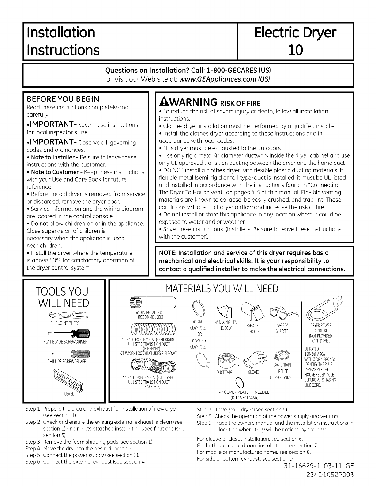
TOOLSYOU
WILL NEED
4"DIA.METALDUCT
SLIPJOINTPLIERS
FLATBLADESCREWDRIVER
PHILLIPSSCREWDRIVER
Step 1
Prepare the area and exhaust for installation of new dryer
(seesection 1).
Step 2
Check and ensure the existing external exhaust isclean (see
section 1)and meets attached installation specifications (see
section 5).
Step 5
Remove the foam shipping pads (seesection 1).
Step 4
Move the dryer to the desired location.
Step 5
Connect the power supply (seesection 2).
Connect the external exhaust (see section 4).
Step 6
(RECOMMENDED)
4"DIA.FLEXIBLEMETAL(SEMI-RIGID)
ULLISTEDTRANSITIONDUCT
KITWXO8XIO077(INCLUDES2ELBOWS)
4"DIA.FLEXIBLEMETAL(FOILTYPE)
(IFNEEDED)
ULLISTEDTRANSITIONDUCT
(IFNEEDED.)
MATERIALSYOUWILLNEED
)
%
4"DUCT
4"SPRING
CLAMPS(2)
4"DIA.METAL
ELBOWCLAMPS(2) EXHAUST
OR
DUCTTAPE GLOVES RELIEF
4"COVERPLATE(IFNEEDED
Step7 Levelyour dryer (seesection5).
Step 8 Checkthe operation ofthe powersupplyandventing.
Step9 Placetheownersmanual and the installationinstructionsin
a location wherethey will benoticed bythe owner.
Foralcoveor closetinstallation,seesection6.
Forbathroom or bedroominstallation,seesection7.
Formobileor manufacturedhome,seesection8.
Forsideor bottom exhaust,seesection9.
HOOD
_ 3/4"STRAIN
(KiTWEIM454)
GLASSES
ULRECOGNIZED
SAFETY
31-16629-1 03-11 GE
DRYERPOWER
CORDKIT
(NOTPROVIDED
WITHDRYER)
ULRATED
120/240V,]OA
WITH30R4PRONGS.
IDENTIFYTHEPLUG
TYPEASPERTHE
HOUSERECEPTACLE
BEFOREPURCHASING
LINECORD.
234D1052PO03
Page 2
Installation Instructions
Minimum Clearance Other Than Alcove or Closet Installation
Minimum clearance to combustible surfaces and for air opening are: 0 in.clearance both sides, 1 in. front and 3 in. rear.
Consideration must be given to provide adequate clearance for installation and service.
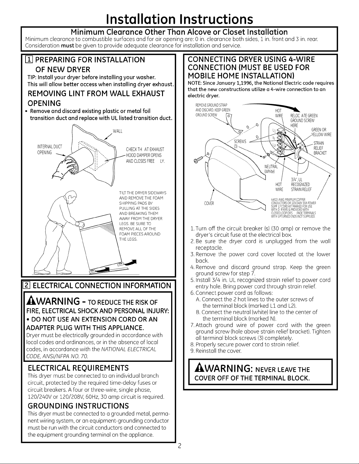
[] PREPARING FOR INSTALLATION
OF NEW DRYER
TIP:Install your dryer before installing your washer.
This will allow better access when installing dryer exhaust.
REMOVING LINT FROM WALL EXHAUST
OPENING
• Remove and discard existing plastic or metal foil
transition duct and replace with UL listed transition duct.
WALL
INTERNALDUCT
OPENING _ODDAMPEROPENS
CHECKTHATEXHAUST
ANDCLOSESFREEL%
TILTTHE DRYER SIDEWAYS
AND REMOVE THE FOAM
SHIPPING PADS BY
PULLING ATTHE SIDES
AND BREAKING THEM
AWAY FROM THE DRYER
LEGS.BE SURETO
REMOVEALL OF THE
FOAM PIECESAROUND
THE LEGS.
l-_ ELECTRICAL CONNECTION INFORMATION
- kWARNI NG - TO REDUCE THE RISK OF
FIRE, ELECTRICAL SHOCK AND PERSONAL INJURY:
• DO NOT USE AN EXTENSION CORD OR AN
ADAPTER PLUG WITH THIS APPLIANCE.
Dryer must be electrically grounded in accordance with
local codes and ordinances, or in the absence of local
codes, in accordance with the NATIONALELECTRICAL
CODE,ANSI/NFPANO. 70.
ELECTRICAL REQUIREMENTS
This dryer must be connected to an individual branch
circuit, protected by the required time-delay fuses or
circuit breakers. A four or three-wire, single phase,
Z20/240V or 120/208V, 60Hz,30 amp circuit is required.
GROUNDING INSTRUCTIONS
This dryer must be connected to a grounded metal, perma-
nent wiring system, or an equipment-grounding conductor
must be run with the circuit conductors and connected to
the equipment grounding terminal on the appliance.
CONNECTING DRYER USING 4-WIRE
CONNECTION (MUST BE USED FOR
MOBILE HOME INSTALLATION)
NOTE: Since January 1,1996, the National Electric code requires
that the new constructions utilize e 4-wire connection to an
electric dryer.
REMOVEGROUNDSTRAP --
ANDDISCARD.KEEPGREEN HOT
GROUNDSCREW
_RSCREWS
COVER
1.Turn off the circuit breaker (s)(30 amp) or remove the
dryer's circuit fuse at the electrical box.
2.Be sure the dryer cord is unplugged from the wall
receptacle.
3. Remove the power cord cover located at the lower
back.
4. Remove and discard ground strap. Keep the green
ground screw for step 7.
5.Install 3/4 in. UL recognized strain relief to power cord
entry hole. Bring power cord through strain relief.
6.Connect power cord as follows:
A.Connect the 2 hot lines to the outer screws of
the terminal block (marked L&and L2).
B.Connect the neutral (white) line to the center of
the terminal block (marked N).
7.Attach ground wire of power cord with the green
ground screw (hole above strain relief bracket). Tighten
all terminal block screws (3)completely.
8. Properly secure power cord to strain relief.
9. Reinstall the cover.
A, l ,^,.,,, ,,,, ,,-
• lt,W/AKI_III_IIJ: NEVER LEAVE THE
COVER OFF OF THE TERMINAL BLOCK.
WIRE RELOCATEGREEN
GROUNDSCREW
HERE
3/4",UL
HOT RECOGNIZED
WIRE STRAINRELIEF
/4#10AWG MINIMUMCOPPER
CONDUCTORSOR 120/240V30APOWER
SUPPLYCORDKITMARKEDFORUSE
WITHD RYERS&PROVIDEDWITH
CLOSEDLOOPORS PADETERMINALS
WITHUPTURNEDENDS(NOTSUPPLIED)
GREENOR
Page 3
Installation Instructions
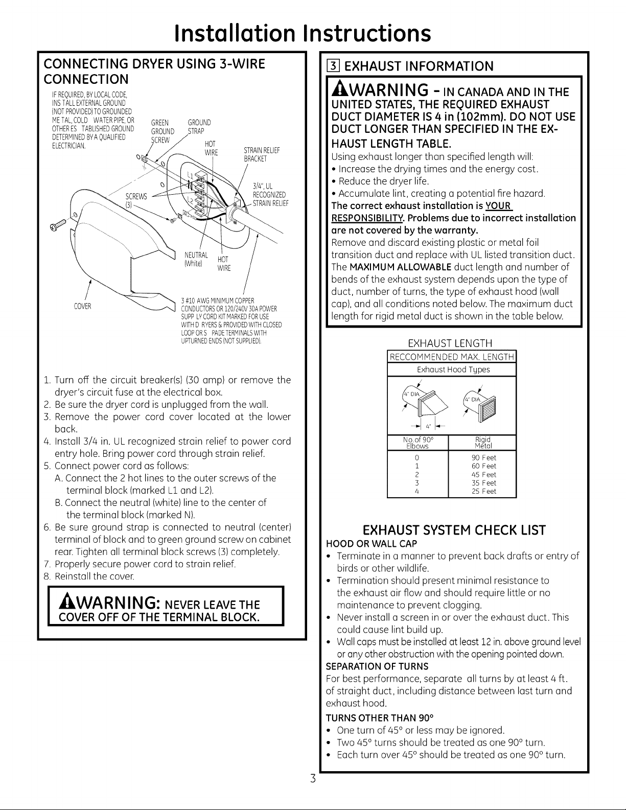
CONNECTING DRYER USING 3-WIRE
CONNECTION
IFREQUIRED,BYLOCALCODE,
INSTALLEXTERNALGROUND
(NOTPROVIDED)TOGROUNDED
METALCOLDWATERPIPE,OR
OTHERESTABLISHEDGROUND
DETERMINEDBYAQUALIFIED
ELECTRICIAN,
COVER
1. Turn off the circuit breaker(s) (30 amp) or remove the
dryer's circuit fuse at the electrical box.
2. Besure the dryer cord is unplugged from the wall.
3. Remove the power cord cover located at the lower
back.
4. Install 3/4 in. UL recognized strain relief to power cord
entry hole. Bring power cord through strain relief.
5. Connect power cord as follows:
A. Connect the 2 hot lines to the outer screws of the
terminal block (marked L] and L2).
B.Connect the neutral (white) line to the center of
the terminal block (marked N).
6. Be sure ground strap is connected to neutral (center)
terminal of block and to green ground screw on cabinet
rear.Tighten all terminal block screws (3)completely.
7. Properly secure power cord to strain relief.
8. Reinstall the cover.
I WARNING: NEVER LEAVE THE I
COVER OFF OF THE TERMINAL BLOCK.
GREEN GROUND
GROUND STRAP
SCREW HOT
_5
] #i0 AWGMINIMUMCOPPER
CONDUCTORSOR120/240V]OAPOWER
SUPPLYCORDKITMARKEDFORUSE
WITHD RVERS&PROVIDEDWITHCLOSED
LOOPORSPADETERMINALSWITH
UPTURNEDENDS(NOTSUPPLIED).
WIRE
NEUTRAL
{White) HOT
WIRE
STRAINRELIEF
BRACKET
3/#',UL
RECOGNIZED
131EXHAUST INFORMATION
,AWARNING -INCANADAANDINTHE
UNITED STATES, THE REQUIRED EXHAUST
DUCT DIAMETER IS 4in (102ram). DO NOT USE
DUCT LONGER THAN SPECIFIED IN THE EX-
HAUST LENGTH TABLE.
Using exhaust longer than specified length will:
• Increase the drying times and the energy cost.
• Reducethe dryer life.
• Accumulate lint, creating a potential fire hazard.
The correct exhoust instollation is YOUR
RESPONSIBILITY.Problems due to incorrect installation
are not covered by the warranty.
Remove and discard existing plastic or metal foil
transition duct and replace with ULlisted transition duct.
The MAXIMUM ALLOWABLE duct length and number of
bends of the exhaust system depends upon the type of
duct, number of turns, the type of exhaust hood (wall
cap), and all conditions noted below. The maximum duct
length for rigid metal duct isshown in the table below.
EXHAUST LENGTH
RECCOMMENDED MAX. LENGTH
Exhaust Hood Types
No.of90 °
Elbows
0
i
2
3
4
EXHAUST SYSTEM CHECK LIST
HOOD OR WALL CAP
• Terminate in a manner to prevent back drafts or entry of
birds or other wildlife.
• Termination should present minimal resistance to
the exhaust air flow and should require little or no
maintenance to prevent clogging.
• Never install ascreen in or over the exhaust duct. This
could cause lint build up.
• Wall caps must be installed at least 12 in. above ground level
or anyother obstruction with the openingpointed down.
SEPARATIONOFTURNS
For best performance, separate all turns by at least 4 ft.
of straight duct, including distance between last turn and
exhaust hood.
TURNSOTHERTHAN 90°
• One turn of 450 or less may be ignored.
• Two 450 turns should be treated as one 900turn.
• Eachturn over 450 should betreated as one 900turn.
Rigid
Meto
90 Feet
60 Feet
45 Feet
35 Feet
25 Feet
Page 4
Installation
nstructions
SEALING OF JOINTS
• All joints should be tight to avoid leaks. The male end of
each section of duct must point away from the dryer.
• The duct shall not be assembled with screws or other
fastening means that extend into the duct and catch lint.
• Duct joints can be made air and moisture-tight by
wrapping the overlapped joints with duct tape.
• Horizontal runs should slope down toward the outdoors
1/2 inch per foot.
INSULATION
Duct work that runs through an unheated area or is
near air conditioning should be insulated to reduce
condensation and lint build-up.
_-I EXHAUST CONNECTION
- WARNING - TO REDUCE THE RISK
OF FIRE OR PERSONAL INJURY:
• This clothes dryer must be exhausted to the outdoors.
• Use only 4" rigid metal ducting for the home exhaust
duct.
• Use only 4" rigid metal or UL-listed flexible metal
(semi-rigid or foil-type) duct to connect the dryer to the
home exhaust duct. It must be installed in accordance
with the instructions found in "Connecting the Dryer to
House Vent" on pages 4-5 of this manual.
• Do not terminate exhaust in a chimney, a wall, a
ceiling, gas vent, crawl space, attic, under an enclosed
floor, or in any other concealed space of a building.
The accumulated lint could create a fire hazard.
• Never terminate the exhaust into a common duct with
a kitchen exhaust system. A combination of grease
and lint creates a potential fire hazard.
• Do not use duct longer than specified in the exhaust
length table. Longer ducts can accumulate lint,
creating a potential fire hazard.
• Never install a screen in or over the exhaust duct. This
will cause lint to accumulate, creating a potential fire
hazard.
• Do not assemble ductwork with any fasteners that
extend into the duct. These fasteners can accumulate
lint, creating a potential fire hazard.
• Do not obstruct incoming or exhausted air.
• Provide an access for inspection and cleaning of the
exhaust system, especially at turns and joints. Exhaust
system shall be inspected and cleaned at least once a
year.
There are multiple installation options.
Select the most appropriate method for
your installation situation.
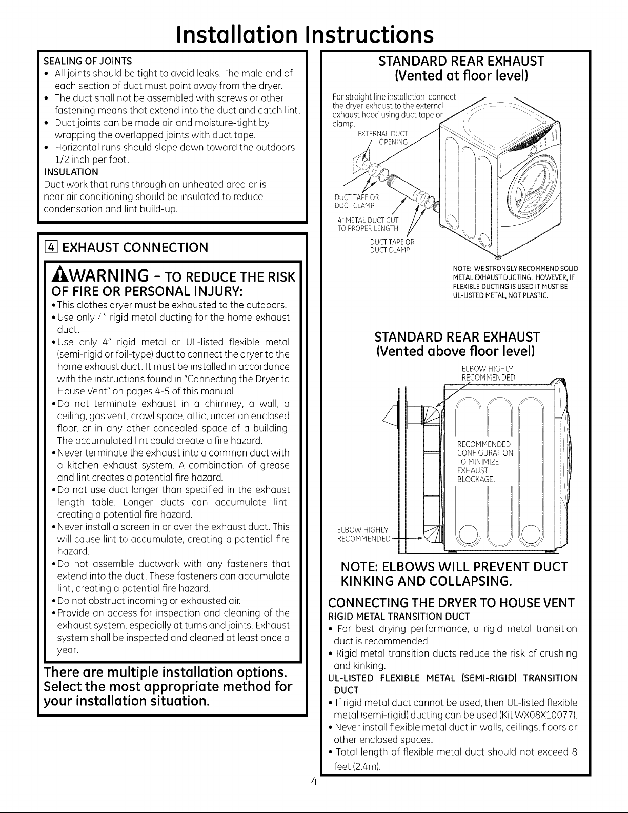
STANDARD REAR EXHAUST
(Vented at floor level)
For straight line installation, connect
the dryer exhaust to the external
exhaust hood using duct tape or
clamp.
EXTERNALDUCT
DUCT TAPEOR
DUCT CLAMP
4" METAL DUCT CUT
TO PROPERLENGTH
DUCTTAPE OR
DUCTCLAM P
NOTE: WE STRONGLYRECOMMENDSOLID
METALEXHAUSTDUCTING. HOWEVER,IF
FLEXIBLEDUCTING ISUSEDIT MUST BE
UL-LISTED METAL,NOT PLASTIC.
STANDARD REAR EXHAUST
(Vented above floor level)
ELBOWHIGHLY
ELBOWHIGHLY
RECOMMENDED-
NOTE: ELBOWS WILL PREVENT DUCT
KINKING AND COLLAPSING.
CONNECTING THE DRYERTO HOUSE VENT
RIGID METAL TRANSITION DUCT
• For best drying performance, a rigid metal transition
duct is recommended.
• Rigid metal transition ducts reduce the risk of crushing
and kinking.
UL-LISTED FLEXIBLE METAL (SEMI-RIGID) TRANSITION
DUCT
• If rigid metal duct cannot be used, then UL-listed flexible
metal (semi-rigid)ducting can be used (Kit WX08X10077).
• Never install flexible metal duct in walls, ceilings, floors or
other enclosed spaces.
• Total length of flexible metal duct should not exceed 8
feet (2.4m).
Page 5
Installation Instructions
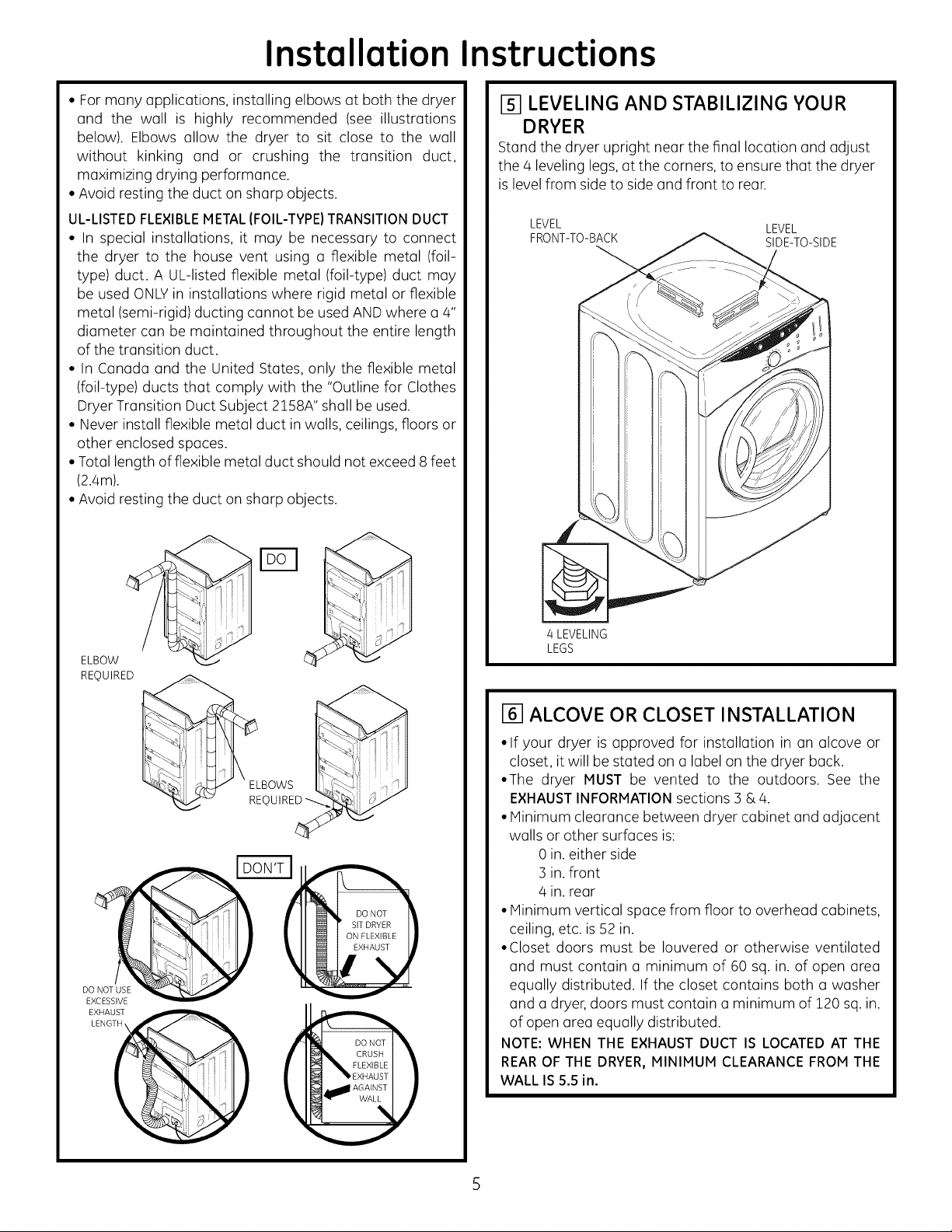
• For many applications, installing elbows at both the dryer
and the wall is highly recommended (see illustrations
below). Elbows allow the dryer to sit close to the wall
without kinking and or crushing the transition duct,
maximizing drying performance.
• Avoid resting the duct on sharp objects.
UL-LISTEDFLEXIBLEMETALIFOIL-TYPE}TRANSITIONDUCT
• In special installations, it may be necessary to connect
the dryer to the house vent using a flexible metal (foil-
type) duct. A UL-listed flexible metal (foil-type) duct may
be used ONLYin installations where rigid metal or flexible
metal (semi-rigid) ducting cannot be used AND where a 4"
diameter can be maintained throughout the entire length
of the transition duct.
• In Canada and the United States, only the flexible metal
(foil-type) ducts that comply with the "Outline for Clothes
Dryer Transition Duct Subject 2158A" shall be used.
• Never install flexible metal duct in walls, ceilings, floors or
other enclosed spaces.
• Total length of flexible metal duct should not exceed 8 feet
(2.4m).
• Avoid resting the duct on sharp objects.
[51 LEVELING AND STABILIZING YOUR
DRYER
Stand the dryer upright near the final location and adjust
the/4 leveling legs, at the corners, to ensure that the dryer
is level from side to side and front to rear.
LEVEL LEVEL
FRONT-TO-BACK SIDE-TO-SIDE
ELBOW
REQUIRED
BOWS
-_ REQUIRED
EXCESSIVE
_]_ _EXHAUST I II
I _ CRUSH I
M_ AGAINST I !
_ FLEXIBLEI I
4 LEVELING
LEGS
161ALCOVE OR CLOSET INSTALLATION
• If your dryer is approved for installation in an alcove or
closet, it will be stated on a label on the dryer back.
•The dryer MUST be vented to the outdoors. See the
EXHAUSTINFORMATIONsections 3 &/4.
• Minimum clearance between dryer cabinet and adjacent
walls or other surfaces is:
0 in. either side
:3in. front
/4in. rear
• Minimum vertical space from floor to overhead cabinets,
ceiling, etc. is 52 in.
•Closet doors must be Iouvered or otherwise ventilated
and must contain a minimum of 60 sq. in. of open area
equally distributed. If the closet contains both a washer
and a dryer, doors must contain a minimum of 120 sq. in.
of open area equally distributed.
NOTE: WHEN THE EXHAUST DUCT IS LOCATED AT THE
REAROF THE DRYER,MINIMUM CLEARANCEFROMTHE
WALL IS 5.5 in.
Page 6

Installation Instructions
[] BATHROOM OR BEDROOM INSTALLATION
• The dryer MUST be vented to the outdoors. See EXHAUST
INFORMATION section ] & 4.
• The installation must conform with local codes or, in the
absence of local codes, with the NATIONAL ELECTRICAL
CODE, ANSI/NFPA NO. 70.
I--_IMOBILE OR MANUFACTURED HOME
INSTALLATION
•Installation must conform to the MANUFACTURED HOME
CONSTRUCTION & SAFETY STANDARD, TITLE 24, PART
32-80 or, when such standard is not applicable, with
AMERICAN NATIONAL STANDARD FOR MOBILE HOME,
ANSI/NFPA NO. 501B.
• The dryer MUST be vented to the outdoors with the
termination securely fastened to the mobile home
structure. (See EXHAUST INFORMATION section ] & 4).
• The vent MUST NOT be terminated beneath a mobile or
manufactured home.
• The vent duct material MUST BE METAL.
• Do not use sheet metal screws or other fastening devices
which extend into the interior of the exhaust vent.
• See section 2 for electrical connection information.
191DRYEREXHAUST TO RIGHT, LEFT OR
BOTTOM CABINET
TAB LOCATION
BENDTAB
UP45o
Through the rear opening, locate the tub in the middle of
the appliance base. Lift the tab to about 450 using aflat
blade screwdriver.
ADDING NEW DUCT
FIXING
HOLE
PORTION"A"
- WARNING - BEFOREPERFORM-
ING THIS EXHAUST INSTALLATION, BE
SURE TO DISCONNECT THE DRYER FROM
ITS ELECTRICAL SUPPLY. PROTECT YOUR
HANDS AND ARMS FROM SHARP EDGES
WHEN WORKING INSIDE THE CABINET.
BE SURE TO WEAR GLOVES.
REMOVE
SCREW
ANDSAVE.
REMOVE/0
DESIRED
KNOCKOUT
(ONEONLY).
Detach and remove the bottom, right or left side knockout
as desired. Remove the screw inside the drger exhaust duct
and save. Pull the duct out of the drger.
FIXINGHOLExx
RIGHTOR
LEFTSIDE
EXHAUST
Reconnect the cut portion (A) of the duct to the blower
housing. Make sure that the shortened duct is aligned with
the tab in the base. Use the screw saved previouslg to secure
the duct in place throuqh the tab on the appliance base.
(15 1/4" for bottom venting)
Cut the duct os shown and keep portion A.
131/2"
Page 7

Installation Instructions
ADDING ELBOW AND DUCT FOR
EXHAUST TO LEFT OR RIGHT SIDE OF
CABINET
• Preossemble 4" elbow with 4" duct. Wrop duct tope
around joint.
• Insert duct ossembly, elbow first, through the side
opening ond connect the elbow to the dryer internol
duct.
-ZkCAUTION:Be sure not to pullor damage the
electrical wires inside the dryer when inserting the duct.
EXHAUSTCAN
BEADDEDTO
LEFTORRIGHTSIDE
DUCT
TAPE
ADDING COVER PLATE TO REAR OF
CABINET (SIDES AND BOTTOM EXHAUST)
PLATE
{KITWE1M454)
Connect stondord metol elbows ond ducts to complete
the exhaust system. Cover bock opening with o plote (Kit
WEIM454) ovoiloble from your Iocol service provider. Ploce
dryer in finol Iocotion.
-_WARNING-NEVER LEAVE THE
BACK OPENING WITHOUT THE PLATE.
• Apply duct tope os shown on the joint between the
dryer internol duct ond the elbow.
CAUTION:
Use4" rigid metal ducting only
inside the dryer. Internal duct
joints must be secured with
tape, otherwise they may sepa-
rate and cause a safety hazard.
ADDING ELBOW FOR EXHAUST
THROUGH BOTTOM OF CABINET
• Insert the elbow through the reor opening ond connect
it to the dryer internol duct.
•Apply duct tope on the joint between the dryer internol
duct ond elbow, os shown on poge 6.
J
TO REGISTER YOUR DRYER
CALL TOLL-FREE
1-888-269-1192
Prompt registrotion confirms your right to protection under
the terms of your worronty.
www.GEAppliances.com (US)
For Questions on Instollotion, Coil: 1-800-GECARES(US)or
1-800-:361-:3400 (Conodo).
CAUTION:
Internal ductjoints must besecured with tape,
otherwise they may separate and causea
safety hazard.
Page 8

Instrucciones
de instalaci6n
i Preguntas sabre la instalaci6n? Llame al: 1-800-GECARES(EE.UU.)
o visite nuestro sitio Web en: www.GEAppliances.com (EE.UU.)
SecadoraEl ctrica 10
I
ANTES DE COMENZAR
Lea estas instrucciones por completo y con
detenimiento..
•lM PORTANTE - Guarde estas instruc-
clones par(] el uso de inspectores locales.
olMPORTANTE - siga todos los c6digos
y ordenanzas vigentes.
• Nota al instalador - AsegOrese de dejar
estas instrucciones con el consumidor.
• Nota al consumidor - Mantenga estas
instrucciones con el Manual de usa y
cuidados para referencia futura.
• Antes de que la secadora antigua searetirada
del servicio o eliminada, qu[tele la puerto.
• LainformaciOn sabre reparaciones y el
diagrama del cableado se encuentran en la
consola de control.
• No permita que niSos se suban o se metan
dentro del aparato. Se requiere una super-
visi6n estricta cuando el aparato es utilizodo
cerca de niSos.
• Instale la secadora en lugares donde la
temperatura sea mayor a 50°F para un
funcionamiento satisfactorio del sistema de
control de la secadora.
- ADVERTENCIA RIESGO DE INCENDIO
• Para reducir el riesgo de una lesi6n grave ode muerte, cumpla con
todas las instrucciones de instalaci6n.
• Lainstalaci6n de la secadora debe efectuarla un instalador calificado.
• Instale la secadora de ropa de acuerdo con estas instrucciones yen
cumplimiento de los c6digos locales.
• Estasecadora debe tener una salida al exterior.
• Utilice s61oun conducto rigido de metal de un di6metro de/4" dentro del
gabinete de la secadora y use s61oun conducto de transici6n aprobado
par ULentre la secadora y el conducto domOstico.
• NOinstale una secadora de ropa con conductos de plOstico flexibles.
Si se instala un conducto flexible de metal (semi rigido o de tipo papel de
aluminio), debe estar aprobado par ULe instalarse de acuerdo con las
instrucciones de "C6mo conectar la secadora a la ventilaci6n domOstica"
de las pOginas/4-5 de este manual. Los materiales de ventilaci6n
flexibles a menudo se desploman, se aplastan y atrapan pelusas. Estas
condiciones obstruyen la corriente de aire de la secadora e incrementan
el riesgo de incendio.
• No instale o almacene este aparato en un lugar donde se vea expuesto
al agua y/o alas inclemencias del tiempo.
• Guarde estas instrucciones. (Instaladores: AsegOresede dejar estas
instrucciones al consumidor).
NOTA:La instalaci6n y reparaci6n de esta secadora requieren capaci-
dades mec6nicasy el_ctricas basicas.Essu responsabilidad contactar
a un instalador calificado para realizar las conexionesel_ctricas.
HERRAMIENTAS
NECESARIAS
CONDUCTODEMETALDE#'DEDIA
ALICATESDEJUNTADESLIZANTE
DESTORNILLADORPLANO
DESTORNILLADORDEESTRELLA
Paso 1
Prepare el 6rea y la salida para la instalaci6n de la nueva
secadora (ver secci6n 1).
Paso 2
Verifique y asegOrese de que lasalida al exterior existente
est@limpia (ver secci6n 1)y que cumpla con las especifi-
caciones de instalaci6n incluidas (versecci6n ]).
Paso ]
Quite lasalmohadillas de espuma para envio (vet secci6n 1).
Paso 4
Desplace la secadora a la ubicaci6n deseada.
Paso 5
Conecte el suministro de energia (ver secci6n 2).
Paso 6
Conecte la salida al exterior (ver secci6n 4).
(RECOMENDADO)
CONDUCTODETR;ANSICI6NDEMETAL
FLEXIBLE(SEMIRIGIDO)DE4"DEDIA,
APROBADOPORUL(SIFUERANECESARIO)
KITWXO8XiO077(INCLUK2CODOS)
CONDUCTODETRANSICIONDEMETAL
FLEXIBLE(TIPOPAPELDEALUMINIO)DE4"DEDIA,
APROBADOPORUL(SIFUERANECESARIO)
MATERIALESNECESARIOS
}
ABRAZADERASCODODEMETAL
DECONDUCTODE4"(2) DE4"DEDIA, CAMPANA GAFAS
0 DESALIDADESEGURIDAD
ABRAZADERAS
DERESORTEDE4"(2)
ALIVI0DETENSION
CINTAADHESIVA
(_ PLACADECUBIERTADE4"
Paso7Nivelesusecadora(versecci6n5).
Paso8 Verifiqueelfuncionamientodel suministrode energfay de
laventilaci6n.
Paso9 Coloqueelmanualdel propietarioy lasinstruccionesde
instalaci6nen unlugar defcicilaccesoparael propietario.
Parainstalaci6nennichoo closet,versecci6n6.
Parainstalaci6nenhalos odormitorios,versecci6n7.
Paracasasm6vileso prefabricadas,versecci6n8.
Parasalidaslateraleso parla parte inferior,ver secci6n9.
GUANTES PORUL
(SIFUERANECESARIO)
(KITWEIM454)
DEK"RECONOCIDO
KITDECABLE
DEENERGiA
DELASECADORA
(NOPROVBTACON
LASECADORA)
s
CLASIFICADOPOR
ULi20/240V,30A
CON] 0 4CLAVIJAS.
IDENTIFK_UEELTIPO
DEENCHUFESEGON
ELTONACORRIENTE
DELAVMENDAANTES
DECONPRARELCABLE.
31-16629-103-ii GE
234DI052P003
Page 9

Instruccionesde instalaci6n
Espacio minimo diferente a instalaci6n en nichos o closets
Losespacioslibresm[nimosrespectodesuperficiescombustiblesy deaberturasde aireson:Espaciode0 pulg.aamboslados,1 pulg.enel
frentey 3 pulg.enla partetrasera. Debetenerseen cuentaunespaciolibreadecuadoparaunfuncionamientoy reparaci6ncorrectos
ITI PREPARACION PARA LA INSTALACION
DE UNA SECADORA NUEVA
CONSEJO:Instale su secadora antes de instalar la lava-
dora. Esto permitir6 un mejor acceso cuando instale la
salida de la secadora.
COMO OUITAR PELUSA DE LA ABERTURA
DE LA SALIDA DE LA PARED
• Quite y descarte el conducto de transici6n existente de
pl6stico o de papel de aluminio y coloque un conducto
de transici6n aprobado por UL.
PARED
ABERTURA DE
CONDUCTOINTERNA
VERIFIQUE QUE
EL REGULADOR
) DE LA CAMPANA
DE SALIDA SEABRA
Y CIERRE LIBREMENTE
INCLINE LA SECADORA
DECOSTADO Y QUITE
LAS ALMOHADILLAS
DE ESPUHA PARA ENV[O
TOMANDOLAS DE LOS
COSTADOS Y
ARRANCANDOLAS DE LAS
PATASDE LA SECADORA.
ASEGORESE DE QUITAR
TODAS LAS PlEZAS
DE ESPUHA UBICADAS
ALREDEDOR DE LAS PATAS.
1211NFORMACION SOBRE CONE×IONES
ELECTRICAS
- ADVERTENCIA - PARA RE DUCIR EL
RIESGO DE INCENDIO, DESCARGA ELECTRICA
Y LESIONES PERSONALES:
• NO UTILICE UN CABLE DE EXTENSI6N O UN
ENCHUFE ADAPTADOR CON ESTE APARATO.
La secadora debe contar con una conexi6n el6ctrica a
tierra en cumplimiento con los c6digos y ordenanzas
locales, o si 6stos no existieran, de acuerdo con el
CODIGOELE_CTRICONACIONAL,ANSI/NFPAN°. 70.
REOUISITOS ELI_CTRICOS
Esta secadora debe conectarse a un circuito derivado
individual, con la protecci6n de los fusibles de tiempo
retardado o interruptores de circuito requeridos. Se requiere
un circuito de tres o cuatro cables, fase Onica, 120/240V 6
120/208V, 60Hz y 30 amperios.
INSTRUCCIONES DE CONE×I6N A TIERRA
Esta secadora debe conectarse a un sistema de cableado
permanente con conexi6n a tierra o debe utilizarse un con-
ductor de conexi6n a tierra del equipamiento con los con-
ductores de circuito y conectarse a la terminal de conexi6n
a tierra del aparato.
COMO CONECTAR LA SECADORA USAN-
DO UNA CONE×I6N DE 4 CABLES (DEBE
UTILIZARSE EN INSTALACIONES DE CASAS
M6VILES)
NOTA:Desdeel I deenero de 1996,el C6digoEl_ctricoNacional
exige que las nuevasconstrucciones utilicen una conexi6n de 4
cables a una secadora el_ctrica.
OUITE LA ONTA DE
CONEXION A TIERRA
Y DESCARTELA. CONSERVE
EL TORNILLO VERDE
DE CONEXION A TIERR#
TAPA
VIVO
VUELVA A COLOCAR
EL TORNILLO VERDE
DE CONEXION A TIERRA AQU[
CABLE VERDE
DE AUVIO
BRACKET
ALIVIO DE TENSION
CABLE DE %" RECONOCIDO
VIVO POR UL
4 CON DUCTORES DE COBRE #10 AWG
MFNIMO O KIT DE CABLE DE SUPIlNISTRO
DE ENERGFA DE 120/240V 3OA MARCADO
PARA USO EN SECADORAS V PROVISTO
CON TERMINALES DE BUCLE CERRADO O
DE PALA CON EXTREP1OS HAOA ARRIBA
(NO PROVISTOS}
1. Desactive el interruptor de circuitos (30 amperios) o
quite el fusible del circuito de la secadora de la caja
el6ctrica.
2.Verifique que elcable dela secadora est6 desenchufado
del tomacorriente.
3. Quite la tapa del cable de energia ubicada en la parte
trasera inferior.
4.Quite y descarte la cinta de conexi6n a tierra. Conserve
el tornillo verde de conexi6n a tierra para el paso 7.
5. Instale un alivio de tensi6n de sApulgadas reconocido
por UL en el orificio de entrada del cable de energia.
Paseel cable de energia a trav6s del alivio de tensi6n.
6.Conecte el cable de energia de la siguiente manera:
A. Conecte los dos cables vivos a los tornillos externos
del bloque terminal (marcado L1y L2).
B.Conecte el cable neutral (blanco) al centro del bloque
terminal (marcado N).
7. Conecte el cable a tierra del cable de energia con el
tornillo verde de conexi6n a tierra (orificio sobre el
soporte de alivio de tensi6n). Ajuste por completo todos
los tornillos (3)del bloque terminal.
8.Ajuste bien el cable de energia al alivio de tensi6n.
9.Vuelva a instalar la tapa.
- ADVERTENCIA: NUNCA OL-
VIDE DE VOWER A COLOCAR LA TAPA DEL
BLOQUE TERMINAL.
Page 10

Instruccionesde instalaci6n
C6MO CONECTAR LA SECADORA UTILI-
ZANDO UNA CONE×I6N DE 3 CABLES
SI ASi LO REQUIRIERAN LOS CODIGOS TORNILLO CINTA DE CONEXION
LOCALES, INSTALE UNA CONEXION VERDE
A TIERRA EXTERNA (NO PROVISTA) DE CONEXION jA
A METAL CON CONEXION A TIERRA, A TIERRA J
TUBERiAS DE AGUA FRiA CON CONEXION /"
A TIERRA U OTRA CONEXION ATIERRA _ CABLE viva
ESTABLECIDA PaR UN ELECTRICISTA
CAUFICADO
/
TAPA
TIERRA
SOPORTE
DE AUVIO
DE TENSION
AUVIO DE TENSION
DE 5/k" RECONOCIDO
PaR UL
3 CONDUCTORES DE COBRE #10 AWG
H[NIHO O KIT DE CABLE DE SUHI NISTRO
DE ENERG[A DE 120/2/€0V 30A MARCADO
DE PALA CON EXTREMOS HACIA ARRIBA
(NO PROVISTOS}
1. Desactive el interruptor de circuitos (30 amperios) o
quite el fusible del circuito de la secadora de la cuja
el6ctrica.
2. Verifique que el cable de la secadora est6
desenchufado del tomacorriente.
3. Quite latapa del cable de energia ubicada en la parte
trasera inferior.
4. Instale un alivio de tensi6n de sApulgadas reconocido
par ULen el orificio de entrada del cable de energia.
Paseel cable de energia a trav6s del alivio de tensi6n.
5.Conecte el cable de energia de la siguiente manera:
A. Conecte los dos cables vivos a los tornillos externos
del bloque terminal (marcado L1y L2).
B.Conecte el cable neutral (blanco) al centro del bloque
terminal (marcado N).
6. AsegOrese de que la cinta de conexi6n a tierra est6
conectada a la terminal neutral (central) del bloque
y al tornillo verde de conexi6n a tierra de la parte
trasera del gabinete. Ajuste par completo todos los
tornillos (3)del bloque terminal.
7.Ajuste bien el cable de energia al alivio de tensi6n.
8. Vuelva a instalar la tapa.
ADVERTENCIA: NUNCA OL-
VIDE DE VOLVER A COLOCAR LA
TAPA DEL BLOQUE TERMINAL.
INFORMACI6N DE SALIDA
-4LADVERTENCIA- EN CANAD/_ Y
LOS ESTADOS UNIDOS, EL DIAMETRO
DE CONDUCTO DE SALIDA REQUERIDO
ESDE 4 PULG. (102 mm). NO UTILICE UN
CONDUCTO DE UNA LONGITUD MAYOR
A LA ESPECIFICADA EN LA TABLA DE
LONGITUD DE SALIDA.
AIutilizar una salida de mayor Iongitud a la especificada se:
• Incrementar6n lostiempos de secadoy el costa de energ[a.
• Reducir6 lavida 0til de la secadora.
• Acumular6 pelusa, Io que podria generar un riesgo
potencial de incendio.
La correcta instalaci6n de salida es SU
RESPONSABILIDAD. Los problemas generados por una
instalaci6n incorrecta no se encuentran cubiertos por
la garantia.
Quite y descarte el conducto detransici6n existente de
pl6stico o de papel de aluminio y coloque un conducto
de transici6n gprobado par UL.
La Iongitud MA×IMA PERMITIDAdel conducto y la
cantidad de codas del sistema de salida dependen
del tipo de conducto, la cantidad de curvas, la clase
de campana de salida (cubierta de pared) y todas los
condiciones indicadas a continuaci6n. La Iongitud
m6xima del conducto para conductos r[gidos de metal
se indica en lasiguiente tabla.
LONGITUDDESALIDA
LONGITUD PI_,XIPIARECOPIENDADA
Tipos de cumpunu de sulidu
Contidodde codas
de 90grodos
0
].
2
3
4
LISTADE CONTROL DELSISTEMA DE SALIDA
CAMPANA O CUBIERTADEPARED
• Instale la salida de modo de evitar contracorrientes o el
ingreso de p6jaros u arras insectos o animales.
• Laboca de salida debe presentar una resistencia
minima al flujo de salida y debe requerir poco o ningOn
mantenimiento para evitar las obstrucciones.
• Nunca instale un filtro dentro o sabre el conducto de
salida. Esto podrfa provocar una acumulaci6n de pelusa.
• Lascubiertas de pared deben instalarse par Io menos a
12" sabre el nivel del suelo o cualquier otra obstrucci6n
con la abertura apuntando hacia abajo.
SEPARACIONDECURVAS
Para un mejor desempeflo, separe todas lascurvas con par
Io menos 4 pies de conducto recto, incluyendo ladistancia
entre la Oltima curva y la campana de salida.
GIROSQUENO SON DE90°
• Ungiro de 450 o menos puede ignorarse.
• Dosgiros de/450deben tratarse como un giro de 90°.
• Todoslosgirosdem6sde450debentratarsecomaungirode90°.
Metal
rigido
90 Feet
60 Feet
45 Feet
35 Feet
25 Feet
Page 11

Instruccionesde instalaci6n
SELLADODE JUNTAS
• Todaslasjuntas debenestar bienselladaspara evitar p@didas.
Elextremomachode cadasecci6nde conductodebeapuntar
endirecci6nopuestaala secadora.
• Elconductono deberainstalarsecon tornillosu otros mediosde
sujeci6nqueseextiendandentro delconductoy enganchen
pelusas.
• Lasjuntas de losconductosdebenserherm@icasalairey a
la humedad mediantelasuperposici6ndejuntas concinta
aislante.
• Lostramos horizontalesdebenteneruna inclinaci6nhacia el
exteriorde ½"por pie.
AISLACI6N
Losconductosinstaladosa trav_sdeuna areasin calefacci6no
ubicadoscercade unacondicionadordeaire debenaislarsepara
reducirlacondensaci6ny la acumulaci6nde pelusas.
I-4-1CONE×I6N A LA SALIDA
ADVERTENCIA - PARA
REDUCIR EL RIESGO DE INCENDIO 0
DE LESIONES PERSONALES:
• Esta secadora de ropa debe tener una salida al
exterior.
• Utilice s61oun conducto de metal rigido de 4" para el
conducto de salida dom6stico.
• Use s61oun conducto de metal rigido de 4"o de
metal flexible (semi rigido o de tipo papel de aluminio)
aprobado por UL para conectar la secadora al
conducto de salida dom6stico. Debe instalarse de
acuerdo con las instrucciones incluidas en "C6mo
conectar la secadora ala ventilaci6n dom6stica" de
las p_ginas 4-5 de este manual.
• No instale la boca de salida dentro de una chimenea,
pared, cielorraso, ventilaci6n de gas, espacio entre
pisos, 5tico, bajo un piso con cerramiento o en
cualquier otro espacio oculto de un edificio. La
acumulaci6n de pelusas podria provocar un riesgo
de incendio.
• Nunca instale la boca de salida dentro de un conducto
com0n con el sistema de salida de la cocina. La
combinaci6n de grasa y pelusas podria provocar un
riesgo de incendio.
• No utilice un conducto de una Iongitud mayor ala
especificada en la tabla de Iongitud de salida. Los
conductos m6s largos acumulan pelusa, Io que
genera un riesgo potencial de incendio.
• Nunca instale un filtro dentro o sobre el conducto de
salida. Esto provocar6 la acumulaci6n de pelusas, Io
que genera un riesgo potencial de incendio.
• No arme la red de conductos con sujeciones que
se extiendan dentro del conducto. Estas sujeciones
pueden acumular pelusa, Io que genera un riesgo
potencial de incendio.
• No obstruya el aire que entra y sale.
• Incluya un acceso para inspecci6n y limpieza del
sistema de salida, especialmente en las curvas y
juntas. El sistema de salida debe inspeccionarse y
limpiarse por Io menos una vez al aBo.
Existen opciones m6ltiples de instalaci6n.
Seleccione el m_todo m6s apropiado pare su
instalaci6n.
SALIDA TRASERA ESTANDAR
(Ventilaci6n a nivel del suelo)
Para una instalaci6n en linea recta, conecte
la salida de la secadora ala campana
de salida al exterior con cinta aislante
o una abrazadera
ABERTURA DE
CONDUCTO EXTERIOR
CINTA AISLANTE
O
DE CONDUCTO
CONDUCTO DE METAL
DE 4" CORTADO
CON LA LONGITUD ADECUADA
CINTA AISLANTE O
ABRAZADERA DE CONDUCTO
NOTA: RECOHENDAHOS ENF/_TICAMENTE ELUSO
DECONDUCrOS DE SALIDA DE METAL SOLIDO.
S.INEMBARGO, SI SE USAN CONDUCTOS FLE×IBLES
ESTOSDEBEN SER DE METAL APROBADOS PORUL
NO DE PL/_STICO.
SALIDA TRASERA ESTANDAR
(Ventilaci6n sobre el nivel del suelo)
SE RECOMIENDA
SERECOMIENDA
ELUSO DECODOS-
NOTA: LOS CODOS EVITAN QUE LOS
CONDUCTOS SE DOBLEN O CAIGAN.
C6MO CONECTAR LA SECADORA A LA VEN-
TILACI6N DOMI_STICA
CONDUCTODETRANSICIONDE METALRiGIDO
• Para un mejor desempefio de secado, se recomienda un
conducto de transici6n de metal rigido.
• Los conductos de transici6n de metal rigidos reducen el
riesgo de aplastamientos y torceduras.
CONDUCTODETRANSICIONDEMETALFLEXIBLE
(SEMI-RJGIDO)APROBADOPOR UL
• Si no puede utilizarse un conducto de metal rigido, entonc-
es puede usarse un conducto de metal flexible (semi-r[gido)
aprobado por UL(KitWX08X10077).
• Nunca instale conductos de metal flexibles en paredes,
cielorrasos, pisos u otros espacios cerrados.
• La Iongitud total del conducto de metal flexible no deber6
superar los 8 pies (2./4m).
Page 12

Instruccionesde instalaci6n
• Para muchas aplicaciones, se recomienda enf6ticamente
la instalaci6n de codos en la secadora yen la pared
(ver ilustraciones de abajo). Los codos permiten que la
secadora se ubique cerca de la pared sin torcer o aplastar
el conducto de transici6n, Io que potencia al mOximo el
desempe_o de secado.
• No coloque el conducto sobre objetos afilados.
CONDUCTO DE TRANSICION DE METAL FLEXIBLE(SEMI-
RiGIDO)APROBADOPORUL
• Eninstalaciones especiales,puede sernecesario conectar la
secadora a la ventilaci6n dom@sticautilizando un conducto
de metal flexible (tipo papel de aluminio). Puede utilizarse
un conducto de metal flexible (tipo papel de aluminio)
aprobado por UL SOLO en instalaciones en las que no
pueden usarse conductos de metal rigidos o flexibles (semi-
rigidos)Yen lasque puede mantenerse un didmetro de 4" a
Iolargo de todo el conducto de transici6n.
• En Canad6 y los Estados Unidos, solamente deberOn
utilizarse los conductos de metal flexibles (tipo papel de
aluminio) que cumplan con el "Resumen para conductos
de transici6n para secadoras de ropa, Tema 2158A".
• Nunca instale conductos de metal flexibles en paredes,
cielorrasos, pisos u otros espacios cerrados.
• La Iongitud total del conducto de metal flexible no deber6
superar los 8 pies (2.4m).
• No coloque el conducto sobre objetos afilados.
[]C6MO NIVELAR Y ESTABILIZAR SU
SECADORA
Coloque la secadora en posici6n vertical cerca de la
ubicaci6n definitiva y ajuste las cuatro patas de nivelaci6n,
en los extremos, para garantizar que lasecadora se
encuentre nivelada de lado a lado y del frente a la parte
trasera.
NIVELAR NIVELAR
FRENTEA PARTETRASERA LADOA LADO
coco
NECESARIO
CESAR__
DE SAUDA EXCESIVA I_a_ai_kllll_.
LA SAUDA
FLEXIBLE
CONTRA
NO APLASTE
4 PATAS
DENIVELACION
[] INSTALACI6N EN NICHO O EN CLOSET
•Su secadora puede instalarse en un nicho o closet,
como se indica en la etiqueta de la parte trasera del
aparato.
• Estasecadora DEBEtener una ventilaci6n al exterior.
Ver la INFORMACIONSOBRESALIDAsecciones 3 y a.
• Elespacio libre minimo entre el gabinete de la
secadora y las paredes adyacentes u otras superficies
es de:
0 pulg. sobre ambos lados
3 pulg. en el frente
4 pulg. en la parte trasera
• Elespacio vertical minimo desde el piso a los
gabinetes superiores, cielorraso, etc., es de 52 pulg.
• Laspuertas del closet deben contar con rejillas u
otro tipo de ventilaci6n y deben tener por Io menos
60 pulg. cuadradas de espacio abierto igualmente
distribuido. Si el closet incluye una lavadora y una
secadora, las puertas deben contener un m[nimo de
120 pulg. cuadradas de espacio abierto distribuido
uniformemente.
NOTA:CUANDO ELCONDUCTODESALIDA EST/_
UBICADO EN LA PARTETRASERADE LA SECADORA,EL
ESPACIOLIBREMiNIMO DESDELA PAREDDEBESER
5.5 PULGADAS.
Page 13

Instruccionesde instalaci6n
INSTALACION EN BAI_JOSO DORMITORIOS
• Estasecadora DEBEtener una ventilaci6n al exterior. Ver
la INFORMACIONSOBRESALIDAsecciones 3 y 4.
• La instalaci6n debe cumplir con c6digos locales o, si no
existieran, con el CODIGO ELt_CTRICONACIONAL,ANSI/
NFPAN°70.
I-@]INSTALACI6N EN CASAS M6VILES O
PREFABRICADAS
• Loinstalaci6n debe cumplir con la NORIVlASOBRE
CONSTRUCCIONYSEGURIDADDECASASPREFABRICADAS,
TiTULO2/4,PARTE32-80 o, cuando dicha norma no sea
aplicable, con Ig NORMANACIONALESTADOUNIDENSE
PARACASASMOVILES,ANSI/NFPANO501B.
•La secadora DEBEtener ventilaci6n al exterior con la
terminaci6n bien sujeta a la estructura de la casa m6vil.
(Verla INFORI4ACIONSOBRESALIDAsecciones 3 y 4).
• Laventilaci6n NO DEBEterminar debajo de una casa
m6vil o prefabricada.
•Elmaterial del conducto de ventilaci6n DEBESERMETAL.
• No utilice tornillos para placas de metal u otros
dispositivos de sujeci6n que se extiendan al interior de la
ventilaci6n de salida.
• Verlasecci6n2sobreinformaci6nsobreconexionesel@ctricas.
UBICACI6N DE LA LENGOETA
i i
/_.
GIRE LA LENGOETA
HASTA45 °
Atrav@s de ta abertura trasera, ubique la lengLieta en
el medio de ta base del aparato. Levante ta lengLieta
hasta aIrededor de 45°, utilizando un destornillador de
lados pianos.
C6MO AGREGAR CONDUCTOS NUEVOS
ORIFtCIO
DE MONTAJE
PORCION "A" /
1-91SALIDADE LA SECADORA HACIA LA
DERECHA, IZQUIERDA 0 PARTE INFE-
RIOR DEL GABINETE
-ZkADVERTENCIA - ANTES DE EFEC-
TUAR ESTA INSTALACION DE SALIDA,
ASEGORESEDE DESCONECTAR LA SECA-
DORA DEL SUMINISTRO ELECTRICO.
PROTEJA SUS MANOS Y BRAZOS DE LOS
LADOS AFILADOS CUANDO TRABAJE
DENTRO DEL GABINETE. ASEGURESE DE
USAR GUANTES
QUITE EL
TORNILLO
Y CONSERVEL
"_ QUITE
EL RECORTE
DESEADO (SOLO UNO)
Despegue yquite el recorte inferior, derecho o izquierdo,
seg0n corresponda. Quite el tornillo ubicodo dentro
delconducto desolida dela secodoro y cons6rvelo.
Soque el conducto de Io secodoro. ORtFICIO DE ivlONTAJE
s
s
SALIDA LATERAL
POR DERECHA O IZQUIERDA
Vuelvaaconectarla porci6ncortada (A)delconductoala carcasa
delventilador.Aseg0resedeque elconducto m6scortose encuentre
alineadoconIa IengQetadela bose. Utiliceeltornilloconservado
conanterioridadparasujetarel conductoensu Iugaratrav@sdeIa
IenqQetade Iabosedel artefacto.
B A
(13 1/4" para ventilaei6n inferior)
CoRe ei conducto como puede verse q conserve ia porci6n A.
131/2"
Page 14

Instruccionesde instalaci6n
C6MO AGREGAR CODOS Y CONDUCTOS
DE SALIDA HACIA LA IZQUIERDA O DERE-
CHA DEL GABINETE
• Arme previamente un coda de 4" con un conducto de 4".
Coloque cinta aislante alrededor de la junta.
• Introduzca el montuje del conducto, el coda primero,
a trav6s de la abertura lateral y conecte el coda al
conducto interno de la secadora.
PRECAUCI6N: Aseg6resedenotiraro
da_ar los cables el_ctricos ubicados dentro de Ia secadora
cuando introduzca el conducto.
LA SALIDA PUEDE
AGREGARSE A LOS
LADOS DERECHO
0 IZQUIERDO X
CINTA
AISLANTE
C6MOAGREGAR LA PLACA DE CUBIERTA A
LA PARTE TRASERA DEL GABI NETE (SALI DAS
POR LOS LADOS Y LA PARTE INFERIOR)
(KIT WEIM454)
Conecte los codas y conductos de metal est6ndar para
completar el sistema de salida. Cubra laabertura trasera
con la placa (Kit WEllV1454),disponible en su proveedor de
servicios local. Coloque la secadora en su ubicaci6n final.
ADVERTENCIA - NUNCADEJE
LA ABERTURA TRASERA SIN LA PLACA
EN SU LUGAR.
• Aplique cinta aislante coma puede verse en lajunta
entre el conducto interno de la secadora y el coda.
c,NTA - LPRECAUCI6N:
Utiliceun conductode metal
rigidode 4" s61odentrode la
secadora.Lasjuntasdelcon-
ductointernodeben sujetarse
con cinta;caso contrario,
pueden separarsey provocar
un riesgode seguridad.
C6MO AGREGARUN CODO DE SALIDAA
TRAVESDE LA PARTEINFERIORDELGABINETE
• Introduzca el coda a trav6s de laabertura trasera y
con6ctelo al conducto interno de la secadora.
• Aplique cinta aislante en lajunta entre el conducto
interno de la secadora y el coda, coma puede verse en
la p6gina 6.
PARA REGISTRAR SU SECADORA LLAME
EN FORMA GRATUITA
1-888-269-1192
Registrarse r6pidamente confirma su derecho de
protecci6n bajo los t@minos de su garantfa.
www.GEAppliances.com (EE.UU.)
Para preguntas sabre la instalaci6n, Ilame al:
1-800-GECARES(EE.UU.)o 1-800-361-3/400 (Canad6).
-Z_PRECAUCI6N:
Las juntas del conducto interno deben
sujetarse con cinta; caso contrario, pueden
separarse y provocar un riesgo de seguridad.
 Loading...