

Page 1

SAFETY INFORMATION .........3
USING THE DRYER
WiFi Connect ........................ 5
Getting Started ...................... 5
Cycles ................................7
Settings ..............................8
Options ..............................8
Loading .............................10
CARE AND CLEANING .......... 11
INSTALLATION
INSTRUCTIONS ..................12
Reversing The Door Swing (Optional) . . 30
Stacking (Optional) ...................32
TROUBLESHOOTING TIPS ..... 36
LIMITED WARRANTY .......... 39
CONSUMER SUPPORT ......... 40
OWNER’S MANUAL &
INSTALLATION
INSTRUCTIONS
GFD85
GFD65
GFD55
GFV55
ENGLISH/FRANÇAIS
Write the model and serial
numbers here:
Model # _________________
DRYERS
Serial # _________________
They are on the label on the front
of the dryer behind the door.
GE is a trademark of the General Electric Company. Manufactured under trademark license.
49-3000206 Rev 1
09-19 GEA
Page 2

THANK YOU FOR MAKING GE APPLIANCES A PART OF YOUR HOME.
Whether you grew up with GE Appliances, or this is your first, we’re happy to have you in the family.
We take pride in the craftsmanship, innovation and design that goes into every GE Appliances
product, and we think you will too. Among other things, registration of your appliance ensures that we
can deliver important product information and warranty details when you need them.
Register your GE appliance now online. Helpful websites and phone numbers are available in the
Consumer Support section of this Owner’s Manual. You may also mail in the pre-printed registration
card included in the packing material.
2 49-3000206 Rev 1
Page 3

IMPORTANT SAFETY INFORMATION.
READ ALL INSTRUCTIONS BEFORE USING THE APPLIANCE
WARNING
• Read all instructions before using the appliance.
•
DO NOT dry articles that have been previously cleaned in, washed in, soaked in, or spotted with gasoline,
dry-cleaning solvents, or other flammable or explosive substances, as they give off vapors that could ignite
or explode.
• DO NOT place items exposed to cooking oils in your dryer. Items contaminated with cooking oils may
contribute to a chemical reaction that could cause a load to catch fire. To reduce the risk of fire due to
contaminated loads, the final part of the tumble dryer cycle occurs without heat (cool down period). Avoid
stopping a tumble dryer before the end of the drying cycle unless all items are quickly removed and spread
out so that the heat is dissipated.
• DO NOT allow children to play on or in this appliance. Close supervision of children is necessary when this
appliance is used near children.
• Before the appliance is removed from service or discarded, remove the door to the drying compartment.
• DO NOT reach into the appliance if the drum is moving.
• DO NOT install or store this appliance where it will be exposed to the weather.
• DO NOT tamper with controls.
• DO NOT climb or stand on this unit.
• DO NOT repair or replace any part of this appliance or attempt any servicing unless specifically recommended
in the user-maintenance instructions or in published user-repair instructions that you understand and have the
skills to carry out.
• Follow all fabric care instructions and warnings to prevent melting of garments or damage to the appliance.
• DO NOT use fabric softeners or products to eliminate static unless recommended by the manufacturer of the
fabric softener or product.
• DO NOT dry articles containing foam rubber or similarly textured rubber-like materials.
• Clean lint screen before or after each load.
• DO NOT operate the dryer without the lint filter in place.
• DO NOT store combustible materials, gasoline or other flammable liquids near the dryer. Keep area around
the exhaust opening and adjacent surrounding areas free from the accumulation of lint, dust and dirt.
• The interior of the appliance and exhaust duct should be cleaned periodically by qualified service personnel.
• Unplug the appliance or turn off the circuit breaker before servicing. Pressing the Power or Start/Pause pad
DOES NOT disconnect power.
• DO NOT operate this appliance if it is damaged, malfunctioning, partially disassembled, or has missing or
broken parts, including a damaged cord or plug.
• DO NOT spray any type of aerosol into, on or near dryer at any time. DO NOT use any type of spray cleaner
when cleaning dryer interior. Hazardous fumes or electrical shock could occur.
• See “ELECTRICAL CONNECTION” located in the Installation Instructions for grounding instructions.
To reduce the risk of fire, explosion, electric shock, or injury to persons when using your
appliance, follow basic precautions, including the following:
SAFETY INFORMATION
READ AND SAVE THESE INSTRUCTIONS
49-3000206 Rev 1 3
Page 4

IMPORTANT SAFETY INFORMATION
READ ALL INSTRUCTIONS BEFORE USING THE APPLIANCE
ADDITIONAL GAS DRYER WARNINGS
WARNING
Failure to follow safety warnings exactly could result in serious injury, death, or property
damage.
- DO NOT store or use gasoline or other flammable vapors and liquids in the vicinity of
this or any other appliance.
- WHAT TO DO IF YOU SMELL GAS:
• DO NOT try to light any appliance.
SAFETY INFORMATION
• DO NOT touch any electrical switch; DO NOT use any phone in your building.
• Clear the room, building, or area of any occupants.
• Immediately call your gas supplier from a neighbor’s phone. Follow the gas supplier’s
instructions.
• If you cannot reach your gas supplier, call the fire department.
- Installation and service must be performed by a qualified installer, service agency, or
the gas supplier.
- Fire or Explosion Hazard
4 49-3000206 Rev 1
Page 5
Getting started
Quick Start
USING THE DRYER
WARNING
WARNING
• Keep flammable materials and vapors, such as
gasoline, away from dryer.
• DO NOT dry anything that has ever had anything
flammable on it (even after washing).
• No washer can completely remove oil.
To reduce the risk of fire, electric shock, or injury to persons, read the IMPORTANT SAFETY
INFORMATION before operating this appliance.
- Fire Hazard
• DO NOT dry anything that has ever had any type of oil
on it (including cooking oils).
• Items containing foam, rubber, or plastic must be dried
on a clothesline.
• Failure to do so can result in death, explosion, or fire.
Throughout this manual, features and appearance will vary from your model.
WiFi Connect (For customers in the United States only - on some models)
Your dryer is GE Appliances WiFi Connect enabled.
Visit geappliances.com/connect and enter your model number to
show you the proper steps to connect your appliance.
Please visit GEAppliances.com/connect to learn more about
connected appliance features, to learn what connected appliance
app’s will work with your smartphone.
WiFi Connectivity: For assistance with the appliance or the
ConnectPlus network connectivity, please call GE Appliances at
800.GE.CARES.
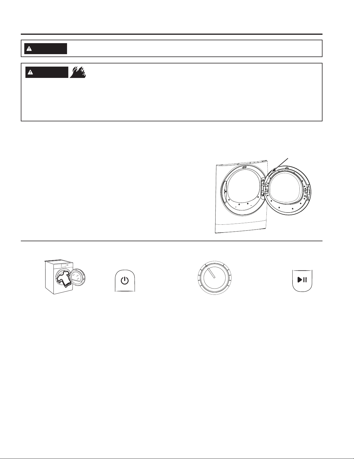
WiFi Label Location
:
Step 1
• Clean lint filter
• Loosely add items.
• Close door.
NOTE: Dryer will not
start with door open.
Step 2 Step 3
• If the screen is dark,
press the Power pad
to “wake up” the
display.
• Select a sensor dry cycle.
(Defaults are set for each dry
cycle. These default settings
can be changed. See the cycle
descriptions for more information.)
• Select TIMED DRY and set Time,
Temp and Level.
Step 4
• Press the Start/
Pause pad.
OR
49-3000206 Rev 1 5
Page 6
Getting started
Features and appearance will vary.
CDA
USING THE DRYER
B F FE
CDA
B F FE
CDA
B F FE
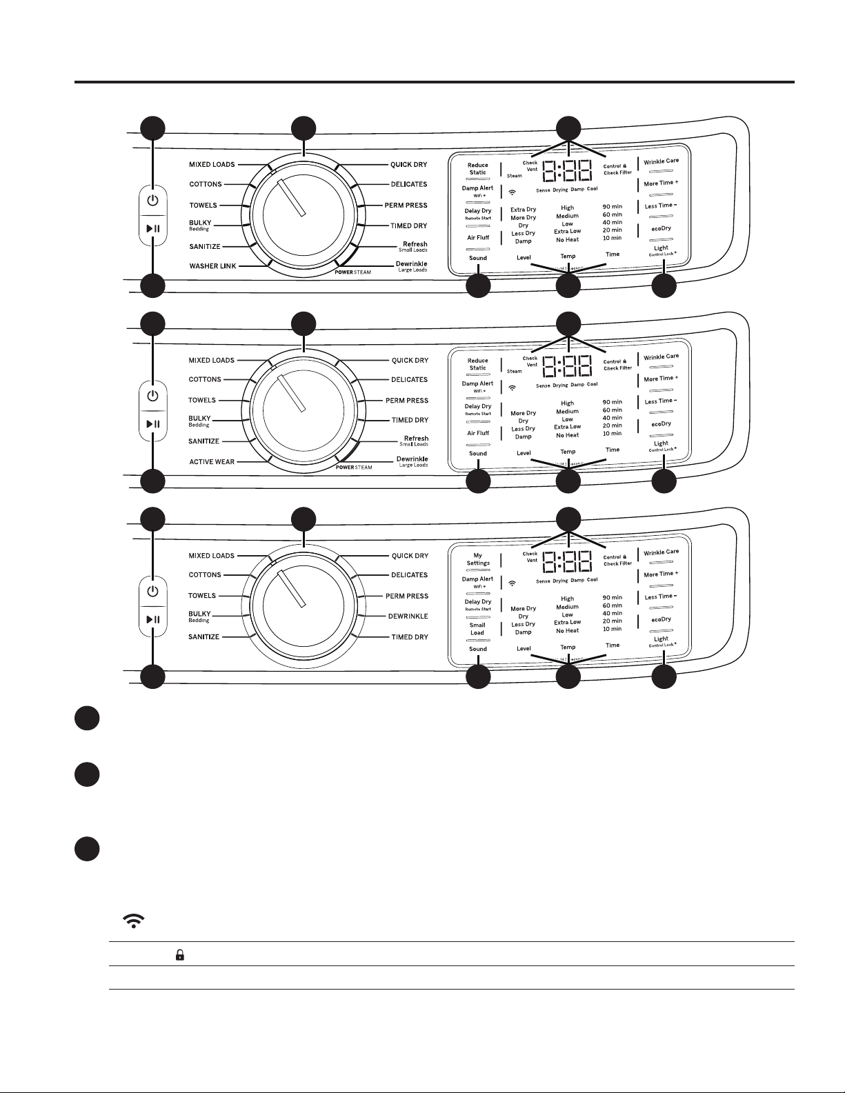
Power
A
Press to “wake up” the display. If the display is active, press to put the dryer into idle mode.
NOTE: Pressing Power does not disconnect the appliance from the power supply.
Start and Pause
B
Press Start to begin the cycle. NOTE: The door must be closed for the dryer to start the cycle. Pressing Start
again will pause the cycle, the Start light will blink and “Pause” will display.
To continue the cycle, press Start again.
Display and Status Lights
C
The display shows the approximate time remaining until the end of the cycle and the dryer cycle status
(Sense, Drying, Damp and Cool).
In addition, the display will show:
(WiFi)
Controls
Check Filter The Check Filter light will stay on for 15 seconds after the cycle stops.
Check Vent
6 49-3000206 Rev 1
Will allow your appliance to communicate with your smartphone for remote appliance
monitoring control and notifications.
The dryer is locked - will blink once if you press any pad or turn the cycle knob.
The Check Vent light indicates an issue has been found due to reduced airflow from a possible
blocked or restricted vent. Checking and/or cleaning the vent system is recommended. See the,
“Check Vent” light is on in the Troubleshooting Tips section.
Page 7
Getting started
USING THE DRYER
Drying
D
Cycles
MIXED LOADS
COTTONS For cottons and most linens. NOTE: ENERGY STAR® models are tested on COTTONS cycle
TOWELS For most towels and linens.
BULKY For large coats, bed spreads, mattress covers, sleeping bags, and similar large/bulky items such as
SANITIZE This option reduces certain types of bacteria including: Staphylococcus aureus, Pseudomonas
WASHER
LINK (on
some models)
ACTIVE
WEAR
QUICK DRY For small loads that are needed in a hurry, such as sport or school uniforms. Can also be used if the
DELICATES For delicate items, special-care fabrics and knits.
PERM PRESS
DEWRINKLE For removing wrinkles from items that are dry or slightly damp. This cycle is not recommended
STEAM
Dewrinkle (on
some models)
STEAM
Refresh (on
some models)
TIMED DRY
Sensor cycles automatically determine fabric dryness.
Timed cycles run for the selected time.
For loads consisting of cottons and poly-blends.
with default settings (Temp setting on Low, Level setting on Dry, and ecoDry default on).
blankets, comforters, jackets, and small rugs.
aeruginosa and Klebsiella pneumoniae. The anti-bacterial process occurs when high heat is used
during a portion of the drying cycle; cool down also will be longer to protect you from a hot garment.
NOTE: Do not use this cycle on delicate fabrics.
When selected (and if connected to a compatible washer through WiFi communication)
the dryer receives load information from the washer to automatically make cycle, dryness,
temperature and time recommendations to optimize drying.
Clothing worn for active sports exercise and some casual wear. Fabrics include new
technology finishes and stretch fibers such as Spandex. Also for clothing labeled Easy Care or
Perma Press: For wrinkle-free and permanent press items.
previous cycle left some items damp, such as collars or waistbands. NOTE: On some models, the time
remaining in the cycle will show counting down in the display.
For wrinkle-free, permanent press and special sports items that need extra drying care.
for delicate fabrics.
For use with larger loads than STEAM Refresh. Ideal for loads left in the dryer for an extended time.
STEAM Dewrinkle is recommended for larger loads (9-13 garments).
NOTE: Steam cycles are not intended for use with towels.
Important - the temperature setting must be set to High and water must be turned on before
running the STEAM Dewrinkle cycle.
For slightly wrinkled dry garments. Significantly reduces wrinkles. After the STEAM Refresh cycle,
the unit will beep (if Sound is selected) and display “00.”
STEAM Refresh is recommended for small loads (3-5 garments).
NOTE: Steam cycles are not intended for use with towels.
NOTE: A single extremely light fabric item may need to have an additional item included in the
STEAM Refresh cycle to achieve optimum results.
Important - the temperature setting must be set to High and water must be turned on before
running the STEAM Refresh cycle.
Use to set your own dry time. To use:
1. Turn cycle dial to TIMED DRY.
2. Increase the drying time by pressing the Time pad.
NOTE: This pad only increases the time. When max time is reached, pressing the pad again
will reset the counter to the lowest setting.
3. Select the Temp.
4. Close the door.
5. Press Start/Pause pad.
49-3000206 Rev 1 7
Page 8
Getting started
Settings
E
Individual settings for cycle minutes (Time), dryness level (Level) and temperature (Temp) can be set from the
minimum (lowest in column) to maximum (highest in column). In general, the higher up the column, the more
energy will be used. NOTE: The selected cycle set Time can be further adjusted, in one minute increments, by
pressing the More Time
Dryness Level - Selection only used for Sensor cycles. Timed cycles run for the selected time.
Extra Dry Use for heavy-duty fabrics or items that should be very dry, such as towels.
More Dry Use for heavy-duty or mixed type fabrics.
Dry Use for a normal dryness level suitable for most loads. This is the preferred cycle for energy savings.
Less Dry Use for lighter fabrics.
USING THE DRYER
F
Damp
Temperature
Medium For synthetics, blends, delicates and items labeled permanent press.
Extra Low For lingerie and special-care fabrics.
No Heat For fluffing items without heat. For use only with the AIR FLUFF cycle.
Options
Reduce Static (on some models)
When selected, the dryer will spray a mist of water onto the load, at the end of the drying cycle, to reduce static.
This option is not available with BULKY, SANITIZE or STEAM cycles.
For leaving items partially damp.
High For regular to heavy cottons.
NOTE: STEAM Dewrinkle and STEAM Refresh require the High temperature setting.
Low For delicates, synthetics and items labeled tumble dry low.
+ and Less Time - pads.
Damp Alert (Damp Alert/WiFi pad)
This option causes the dryer to beep when clothes have dried to a damp level. Remove items that you wish
to hang dry. The Damp Alert will only beep when this option is selected (but the dry cycle will keep running).
Removing clothes and hanging them when they are damp, can reduce the need to iron some items.
Delay Dry
Press the Delay Dry pad to set the delay start time in 1 hour increments up to 24 hours, and then back to clear
(0 hours). After selecting the delay start time, press Start and the delay time will count down the time remaining
until the cycle starts. NOTE: To set the amount of delay time faster, you can press and hold the Delay Dry pad.
Delay Dry for WiFi Connected Dryers
You have two options to set Delay Dry using your smartphone.
Option 1: Follow Delay Dry instructions. You can use the GE Appliances Laundry App to adjust the amount of
time via your smartphone.
Option 2 - Remote Start: Set your dryer to “AP” using the Delay Dry pad. This allows you to use the GE
Appliances Laundry App via your smartphone to start your dryer remotely at the time of your choosing. If the
dryer is set to AP with no activity, it will start the dryer 24 hours later.
Air Fluff (on some models)
Provides 10 minutes of tumbling time with no heat. NOTE: On models without AIR FLUFF cycle, select TIMED
DRY and set Temp to No Heat.
Sound
Use the Sound pad to change the volume of the pad presses and the end of cycle signal. Press the pad until
you reach the desired volume or off. The clothes should be removed when the end of cycle signal goes off so
wrinkles do not set in.
NOTE:
• Remove garments promptly at the sound of signal. Place clothes on hangers so wrinkles will not set in.
• Use the Sound especially when drying fabrics like polyester, knits and permanent press. These fabrics should
be removed so wrinkles will not set in.
8 49-3000206 Rev 1
Page 9

Getting started
Options (cont.)
F
Wrinkle Care
Use this option to minimize the wrinkles in clothes. It provides 1 hour of no-heat tumbling after the clothes are
dry. If you are using the cycle Sound and you select the Wrinkle Care option, a signal will sound at the end of
the drying time and several times during the Wrinkle Care cycle. This will remind you that it is time to remove
the clothes.
More Time + / Less Time -
The selected cycle set Time can be further adjusted, in one minute increments, by pressing the More Time +
and Less Time - pads.
ecoDry
Available for BULKY, TOWELS, COTTONS, MIXED LOADS, ACTIVE WEAR and DELICATES. When the
ecoDry pad is pressed, cycle settings change to reduce the total energy consumption of the selected sensor
cycle. NOTE: Cycle times will change when ecoDry is selected. The ecoDry option will default to on for
COTTONS. For optimal energy savings, turn ecoDry on. For optimal drying times, turn ecoDry off. NOTE:
Energy savings will vary across loads and cycles.
Light
The drum light will turn on if the Light pad is pressed or the door is opened. It will turn off when the door is shut,
the Light pad is pressed again or after 5 minutes if the door is left open.
Small Load (on some models)
Select to use for a small load with any sensor cycle (except SANITIZE).
USING THE DRYER
My Settings
As the cycle selector knob is turned, the Time (timed dry), Level (dryness level) and Temp (temperature)
settings change to automatic pre-set default settings. If you desire a different setting, press the appropriate
pad(s). Then press and hold the My Settings pad for 3 seconds and the dryer will “remember” these settings
for that Knob Selection. In the future, when you turn the selector knob to that cycle, your settings will be
automatically recalled. NOTE: Signal sound cannot be set for My Settings.
Control Lock
You can lock the controls to prevent any selections from being made. Or you can lock the controls after you
have started a cycle. Children cannot accidentally start the dryer by touching pads with this option selected.
To lock/unlock the dryer controls, press and hold the Light pad for 3 seconds. The control lock icon will flash
while locking/unlocking, stay on when locked, and turn off when unlocked.
NOTE: The Power pad can still be used when the machine is locked.
WiFi (Damp Alert/WiFi pad)
Press and hold the Damp Alert/WiFi pad for 3 seconds to activate.
49-3000206 Rev 1 9
Page 10
Loading
Always follow fabric manufacturer’s care label when laundering.
Sorting and Loading Hints
WARNING
• Keep flammable materials and vapors, such as
gasoline, away from dryer.
• DO NOT dry anything that has ever had anything
flammable on it (even after washing).
• No washer can completely remove oil.
USING THE DRYER
As a general rule, if clothes are sorted properly for the washer, they are sorted properly for the dryer. Try also to sort
items according to size. For example, do not dry a sheet with socks or other small items.
Do not add fabric softener sheets once the load has become warm. They may cause fabric softener stains. Bounce®
Fabric Conditioner Dryer Sheets have been approved for use in this dryer when used in accordance with the
manufacturer’s instructions.
Do not overload. This wastes energy and causes wrinkling.
- Fire Hazard
• DO NOT dry anything that has ever had any type of oil
on it (including cooking oils).
• Items containing foam, rubber, or plastic must be dried
on a clothesline.
• Failure to do so can result in death, explosion, or fire.
Drying Rack (on some models)
A handy drying rack may be used for drying delicate items such as washable sweaters.
To install the drying rack, place the rack all the way into the dryer drum and fit its feet down and securely into place
in the dryer.
NOTES:
• The drying rack must be used with the TIMED DRY cycle. Use with sensor cycles may
result in damp items or extended cycle times.
• Do not use this drying rack when there are other clothes in the dryer.
• If your model did not come with a drying rack, order WE02X29449 on-line at
GEApplianceparts.com, 24 hours a day or by phone at 877.959.8688 during normal
business hours.
10 49-3000206 Rev 1
Page 11
Care and cleaning
Interior and Duct
The interior of the appliance and exhaust duct should be cleaned once a year by qualified service personnel.
The Exhaust Duct: Inspect and clean the exhaust ducting at least once a year to prevent clogging. A partially clogged
exhaust can lengthen the drying time.
Follow these steps:
1
Turn off electrical supply by disconnecting the plug from the wall socket.
2
Disconnect the duct from the dryer.
3
Vacuum the duct with the hose attachment and reconnect the duct.
The Exhaust Hood: Check with a mirror that the inside flaps of the hood move freely when operating. Make sure that there
is no wildlife (birds, insects, etc.) nesting inside the duct or hood.
Exterior
Wipe or dust any spills or washing compounds with a damp cloth. Dryer control panel and finishes may be damaged
by some laundry pretreatment soil and stain remover products. Apply these products away from the dryer. The fabric
may then be washed and dried normally. Damage to your dryer caused by these products is not covered by your
warranty.
CARE AND CLEANING
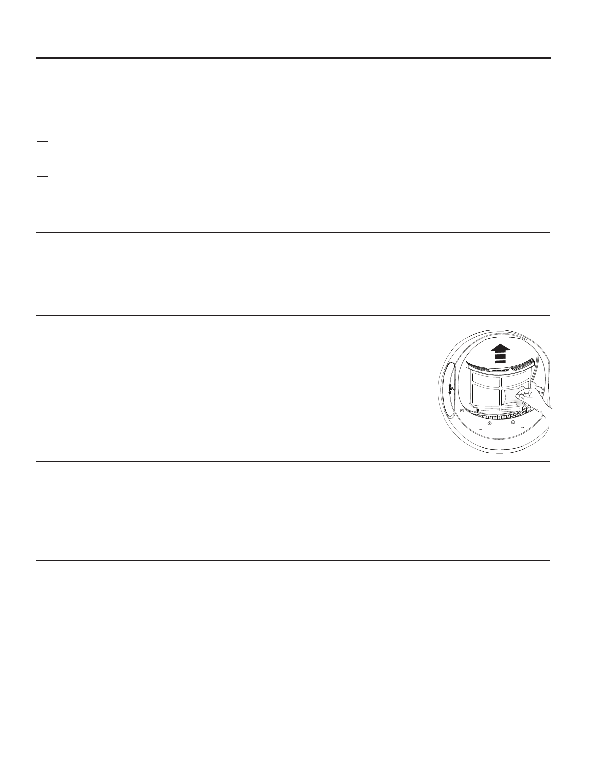
Lint Filter
Clean the lint filter before each use.
Remove by pulling straight up. Run your fingers across the filter. A waxy buildup may form
on the lint filter from using dryer added fabric softener sheets.
To remove this buildup, wash the lint screen in warm, soapy water. Dry thoroughly and
replace.
Vacuum the lint from the dryer lint filter area if you notice a change in dryer performance.
NEVER OPERATE THE DRYER WITHOUT ITS FILTER IN PLACE.
Stainless Steel
To clean stainless steel surfaces use a damp cloth with a mild, non-abrasive cleaner suitable for stainless steel
surfaces. Remove the cleaner residue and then dry with a clean cloth.
The stainless steel used to make the dryer drum provides the highest reliability available in a GE Appliances dryer.
If the dryer drum should be scratched or dented during normal use, the drum will not rust or corrode. These surface
blemishes will not affect the function or durability of the drum.
Drum Light
The drum light is an LED light. Replacement must be done by a qualified technician.
49-3000206 Rev 1 11
Page 12
Installation
Instructions
If you have any questions, call GE Appliances at 800.GE.CARES
(800.432.2737)
In Canada, call 800.561.3344
BEFORE YOU BEGIN
Read these instructions completely and carefully.
or visit our Website at: GEAppliances.com
or visit www.GEAppliances.ca
WARNING
Dryer
• IMPORTANT – Save these instructions for
local electrical inspector’s use.
• IMPORTANT – Observe all governing
codes and ordinances.
• Install the clothes dryer according to the
manufacturer’s instructions and local codes.
• Note to Installer – Be sure to leave these
instructions with the Consumer.
• Note to Consumer – Keep these instructions for
future reference.
• Clothes dryer installation must be performed by a
qualified installer.
• This dryer must be exhausted to the outdoors.
• Before the old dryer is removed from service or
discarded, remove the dryer door.
• Service information and the wiring diagram are
located in the control console.
• Do not allow children on or in the appliance. Close
supervision of children is necessary when the
appliance is used near children.
• Proper installation is the responsibility of the installer.
• Product failure due to improper installation is not
covered under the Warranty.
• Install the dryer where the temperature is above
50°F for satisfactory operation of the dryer control
system.
• Remove and discard existing plastic or metal foil
duct and replace with UL-listed duct.
If you are planning to stack the washer and dryer, order
Stacking Kit number GFA28KITN to be used for this
dryer. Kit sold separately.
- Risk of Fire
• Clothes dryer installation must be performed by a
qualified installer.
• Install the clothes dryer according to these
instructions and local codes.
• DO NOT install a clothes dryer with flexible plastic
venting materials. If flexible metal (semi-rigid or
foil-type) duct is installed, it must be UL-listed and
installed in accordance with the instructions found
in “Connecting the Dryer to House Vent” later in
this manual. Flexible venting materials are known
to collapse, be easily crushed and trap lint. These
conditions will obstruct dryer airflow and increase
the risk of fire.
• DO NOT install or store this appliance in any
location where it could be exposed to water or
weather.
• To reduce the risk of severe injury or death, follow
all installation instructions.
• Save these instructions. (Installers: Be sure to
leave these instructions with the customer.)
FOR GAS DRYERS ONLY
In the Commonwealth of Massachusetts,
the following installation instructions apply:
• Installation must be performed by a qualified or
licensed contractor, plumber, or gasfitter qualified
or licensed by the State.
• If using a ball valve, it shall be a T-handle type.
• A flexible gas connector, when used, must not
exceed 4 feet.
12 49-3000206 Rev 1
Page 13

Installation Instructions
UNPACKING YOUR DRYER
Tilt the dryer sideways and remove the foam shipping pads by pulling at the sides and
breaking them away from the dryer legs. Be sure to remove all of the foam pieces around
the legs.
Remove the bag containing the literature.
DRYER
DIMENSIONS
*NOTE:
With leveling legs retracted: 39-3/4 (101 cm).
With leveling legs fully extended: 40-5/8 (103.1 cm).
With Optional Pedestal: 55-1/2” (141 cm) Min. - 56-5/8” (143.8 cm) Max.
Stacked: 79-1/8” (201 cm).
28”
(71.2 cm)
*39-3/4”
(101 cm)
Front View
STEAM WATER HOSES (for steam dryer models only):
GE Appliances strongly recommends the use of factory
specified parts. These hoses are manufactured and tested
to meet GE Appliances specifications.
GE Appliances strongly recommends the use of new water
supply hoses. Hoses degrade over time and need to be
replaced every 5
and water damage.
Parts and Accessories
Order on-line at GEApplianceparts.com, 24 hours a day
or by phone at 877.959.8688 during normal business hours.
years to reduce the risk of hose failures
Part Number Accessory
WE25X20060
WE49X25794
WE1M847 Long Hose
OR SEPARATELY
WE1M847 Long Hose and
WE1M848 Short Hose
54-1/4” (137.8 cm)
31-3/8” (79.7 cm)
Side View
Complete Kit (hoses, Y-adapter, washers)
or
Kit (Short hose, Y-adapter, washers)
and
ACCESSORIES:
Order on-line at GEApplianceparts.com, 24 hours a day or
by phone at 877.959.8688 during normal business hours.
49-3000206 Rev 1 13
Part Number Accessory
GFP1528SNWW
GFP1528PNSN
GFP1528PNRS Royal Sapphire Pedestal
GFP1528PNDG Diamond Gray Pedestal
GFA28KITN Stacking Kit for Dryer over Washer
PM08X10085
WE02X29449
White Pedestal
Satin Nickel Pedestal
Flexible Metal Dryer Transition Duct
Clothes Dryer Drying Rack
Page 14
Installation Instructions
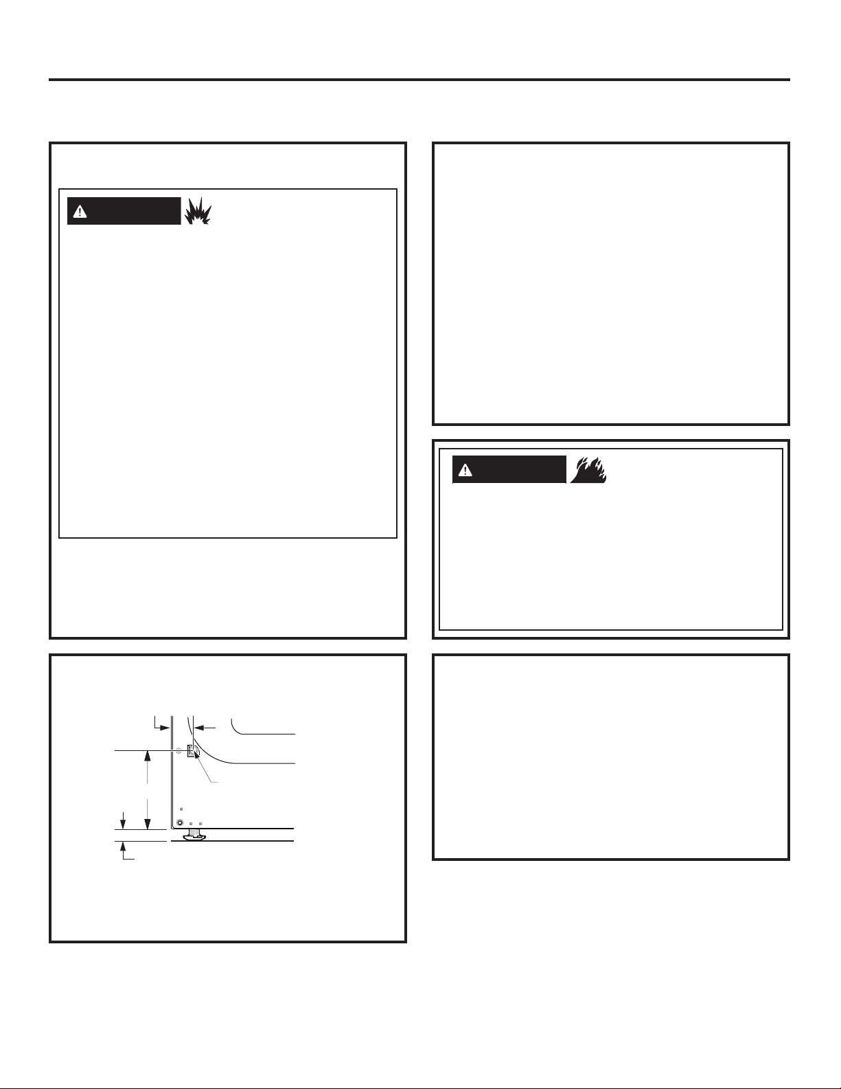
REQUIREMENTS FOR ALCOVE OR
CLOSET INSTALLATION
WARNING
Keep flammable materials and vapors, such as gasoline,
away from dryer.
Place dryer at least 18” (46 cm) above the floor for a
garage installation.
Failure to do so can result in death, explosion, or fire.
• The dryer MUST be vented to the outdoors.
• Minimum clearance between dryer cabinet and
adjacent walls or other surfaces is:
0” either side*
0” front
0” rear
0” top
* For improved performance, a 1/2” clearance is
suggested on each side.
• The rear of the dryer should face a wall.
• Consideration must be given to provide adequate
clearance for installation and service.
• Closet doors must be louvered or otherwise
ventilated and have at least 60 square inches of
open area. If the closet contains both a washer
and a dryer, doors must contain a minimum of 120
square inches of open area.
NOTE: WHEN THE EXHAUST DUCT IS LOCATED AT
THE REAR OF THE DRYER, THE CONFIGURATION
OF THE DUCTING MAY REQUIRE GREATER
CLEARANCE.
Gas Dryers Only:
• No other fuel burning appliance shall be installed in
the same closet as a gas dryer.
• The dryer must be disconnected from the gas
supply piping during pressure testing at pressures
greater than 1/2 psi (3.5 kPa).
• A 1/8 inch NPT minimum plugged tapping,
accessible for test gauge connection, must be
installed immediately upstream of the gas supply
connection to the dryer.
- Explosion Hazard
MINIMUM CLEARANCE OTHER
THAN ALCOVE OR CLOSET
INSTALLATION
Minimum clearance to combustible surfaces and for
air opening are: 0” both sides*, 0” rear and 0” top.
* For improved performance, a 1/2” clearance is
suggested on each side.
The rear of the dryer should face a wall.
Consideration must be given to provide adequate
clearance for installation and service.
MOBILE OR MANUFACTURED
HOME INSTALLATION
• Installation MUST conform to the
MANUFACTURED HOME CONSTRUCTION
AND SAFETY STANDARD, TITLE 24, PART
3280 or STANDARD FOR MOBILE HOMES
CAN/CSA-Z240 MH, or, when such standards
are not applicable, with AMERICAN NATIONAL
STANDARD FOR MOBILE HOME, ANSI/NFPA
NO. 501B.
• The dryer MUST be vented to the outdoors.
• The exhaust vent MUST be securely fastened to a
non-combustible portion of the mobile home.
• The vent MUST NOT be terminated beneath a
mobile or manufactured home.
• The vent duct material MUST BE METAL.
• KIT 14-D346-33 MUST be used to attach the dryer
securely to the structure.
• The vent MUST NOT be connected to any other
duct, vent or chimney.
• DO NOT use sheet metal screws or other
fastening devices which extend into the interior of
the exhaust vent.
• Provide an opening with a free area of at least 25
square inches for introduction of outside air into
the dryer room.
• See the sections for electrical connection information.
14 49-3000206 Rev 1
Page 15
Installation Instructions
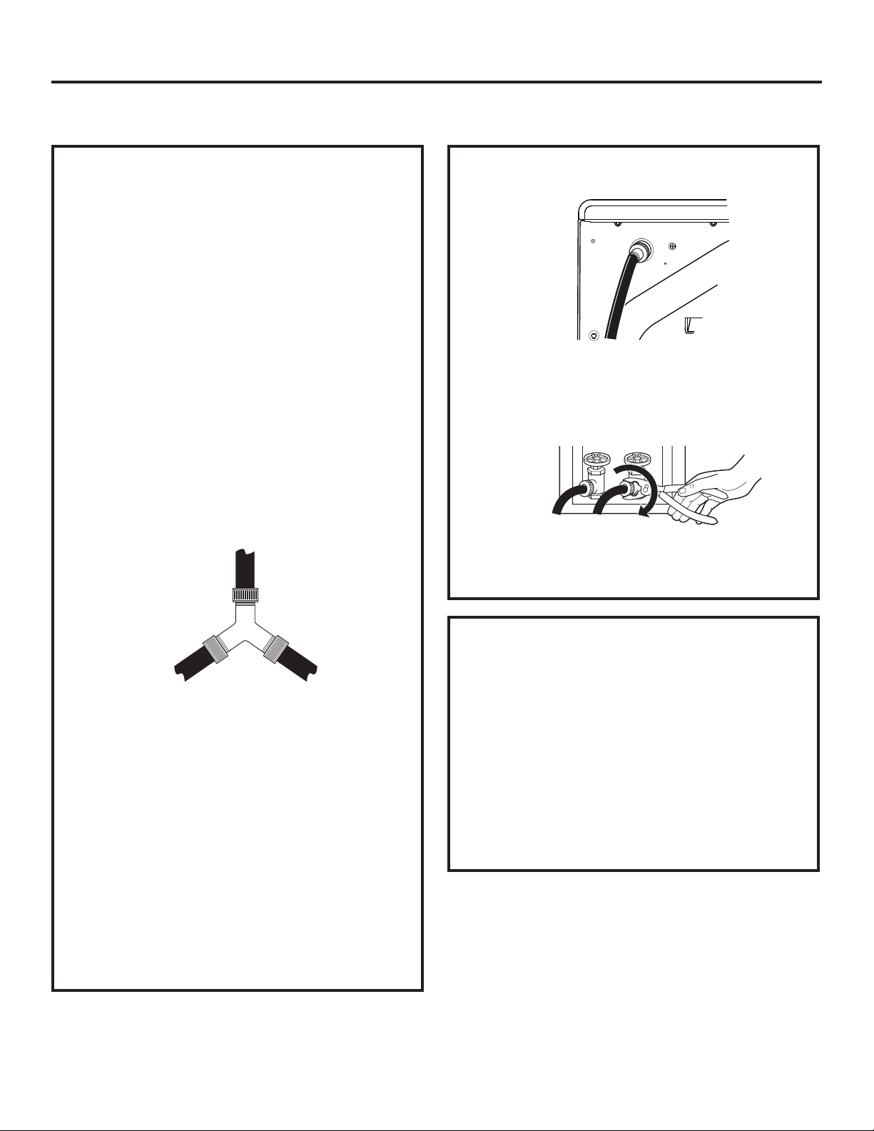
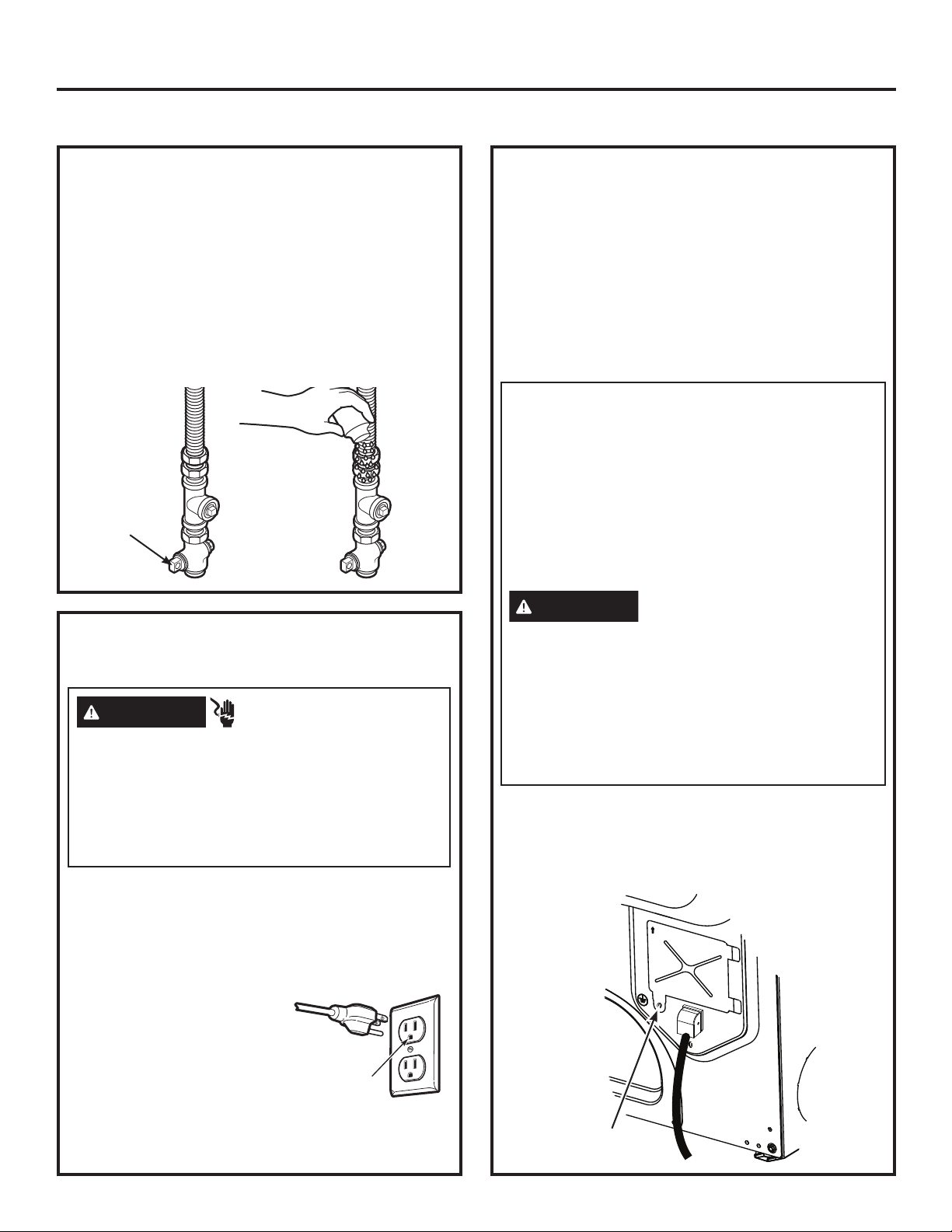
CONNECTING INLET HOSES (for steam dryer models only)
CONNECTING INLET HOSES
To produce steam, the dryer must connect to
the cold water supply. Since the washer must
also connect to the cold water, a “Y” connector
is inserted to allow both inlet hoses to make that
connection at the same time.
NOTE: Use new inlet hoses; never use old
hoses.
1. Turn the cold water faucet off. Remove the
washer inlet hose from the washer fill valve
connector (cold).
2. Ensure the rubber flat washer is in place and
attach one female coupling of the short hose
provided onto the washer fill valve connector.
Tighten by hand until firmly seated.
3. Attach one male end of the “Y” connector to
the other female coupling of the short hose.
Ensure the rubber flat washer is in place.
Tighten by hand until firmly seated.
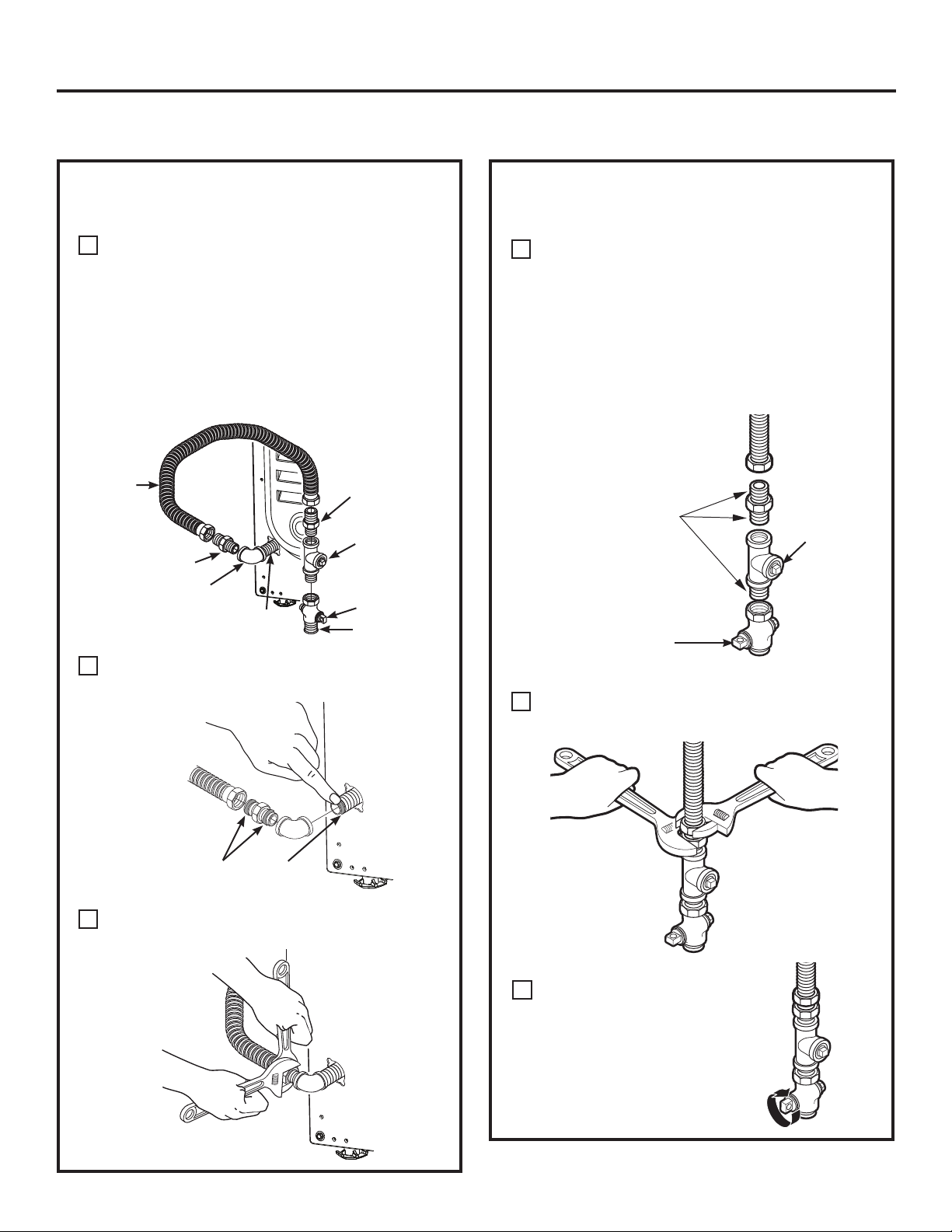
CONNECTING INLET HOSES (cont.)
7. Using pliers, tighten all the couplings with an
additional two–thirds turn.
NOTE: Do not overtighten. Damage to the
couplings may result.
8. Turn the water faucet on.
9. Check for leaks around the ‘’Y’’ connector,
faucet and hose couplings.
4. Insert the filter screen in the coupling of the
washer’s inlet hose. If a rubber flat washer is
already in place remove it before installing the
filter screen. Attach this coupling to one male
end of the ‘’Y’’ connector. Tighten by hand until
firmly seated.
5. Ensure the rubber flat washer is in place and
attach a 4 ft. to 6 ft. long water inlet hose (may
need to be purchased separately) to one male
end of the ‘’Y’’ connector. Tighten by hand until
firmly seated.
6. Ensure the rubber flat washer is in place and
attach the other end of the dryer’s long inlet
hose to the fill valve connector at the bottom
of the dryer back panel. Tighten by hand until
firmly seated.
WATER SUPPLY REQUIREMENTS
Hot and cold water faucets MUST be installed
within 42 in. (107 cm) of your washer’s water
inlet. The faucets MUST be 3/4 in. (1.9 cm)
garden hose-type so inlet hoses can be
connected. Water pressure MUST be between
10 and 120 pounds per square inch. Your
water department can advise you of your water
pressure.
NOTE: A water softener is recommended
to reduce buildup of scale inside the steam
generator if the home water supply is very hard.
49-3000206 Rev 1 15
Page 16
Installation Instructions
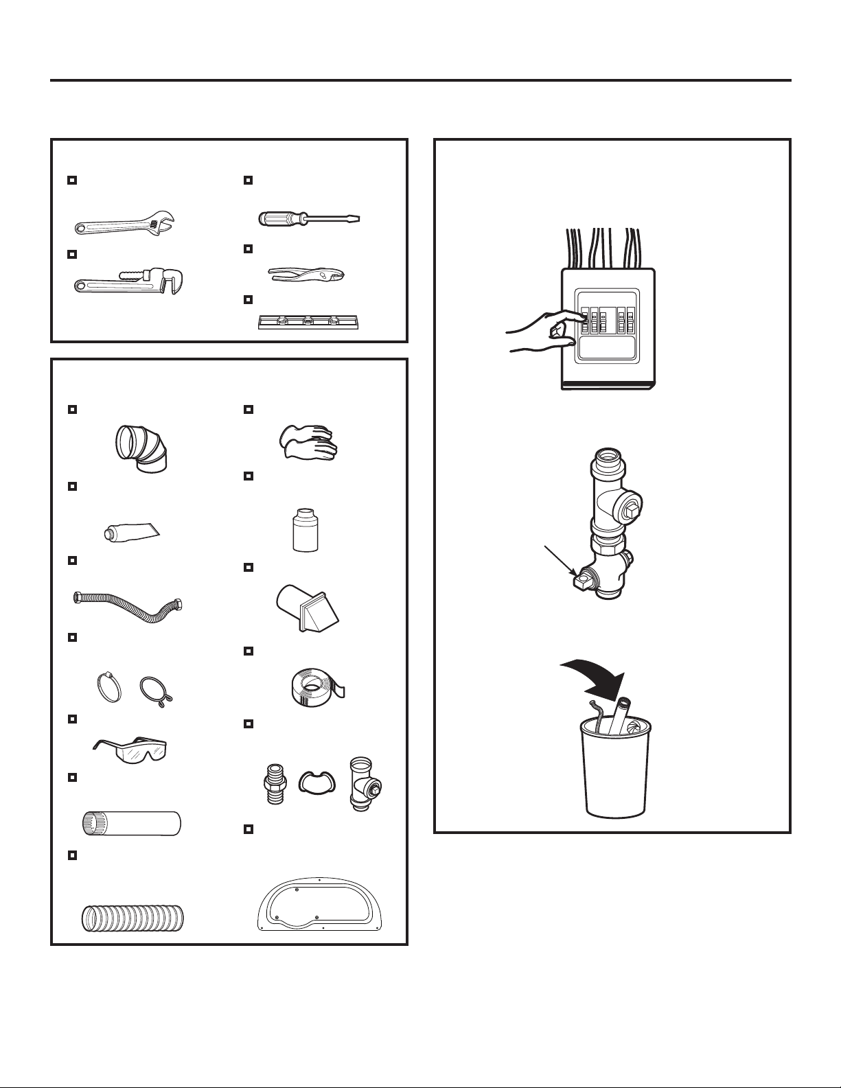
CONNECTING A GAS DRYER (skip for electric dryers)
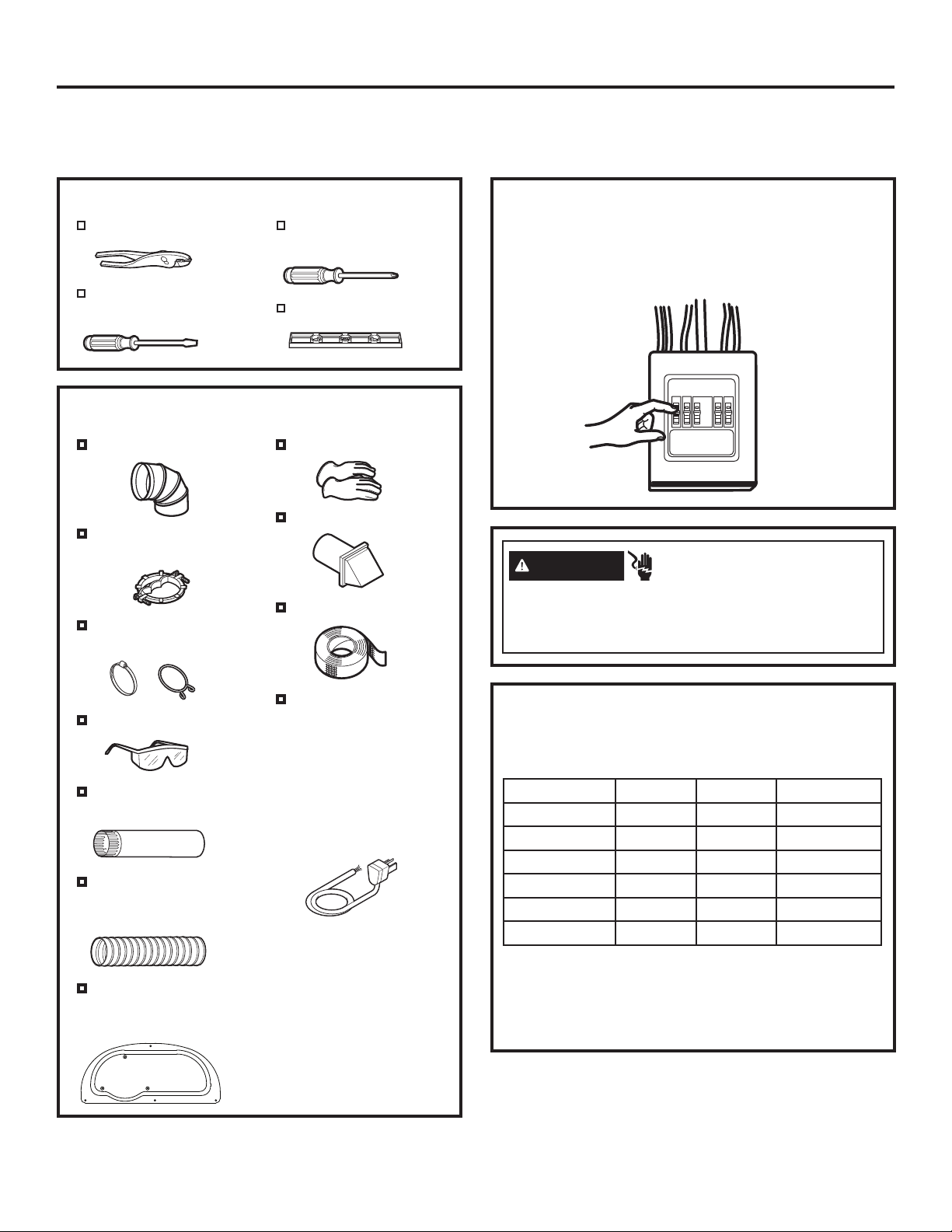
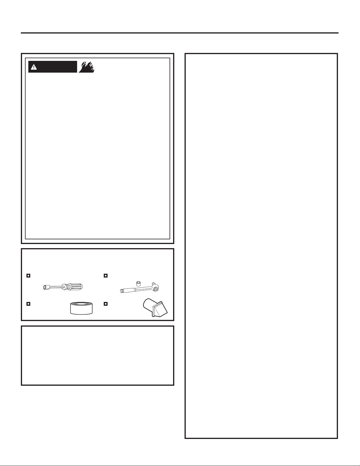
TOOLS YOU WILL NEED
Ŷ
10” Adjustable
wrenches (2)
Ŷ
8” Pipe wrench
Ŷ
Flat-blade
screwdriver
Ŷ
Slip-joint pliers
Ŷ
Level
MATERIALS YOU WILL NEED
Ŷ
4” dia. metal elbow
Ŷ
Pipe compound or
PTFE tape
Ŷ
Flexible gas line
connector
Ŷ
Gloves
Ŷ
Soap solution for
leak detection
Ŷ
Exhaust hood
• Before beginning the installation, turn off the circuit
breaker(s) or remove the dryer’s circuit fuse(s) at
the electrical box. Be sure the dryer
cord is unplugged from the wall.
• Turn the dryer’s gas shut-off valve in the supply line
to the OFF position.
Shut-off
Valve
Ŷ
Duct clamps (2) or
Spring clamps (2)
Ŷ
Safety glasses
Ŷ
4” dia. metal duct
(recommended)
Ŷ
4” dia., UL-listed
flexible metal duct
(if needed)
Ŷ
Duct tape
Ŷ
Gas pipe adapters (2),
elbow and pipe plug
Ŷ
Access Panel
(Kit WE16X29317)
(if needed)
• Disconnect and discard old flexible gas connector
and ducting material.
16 49-3000206 Rev 1
Page 17
Installation Instructions
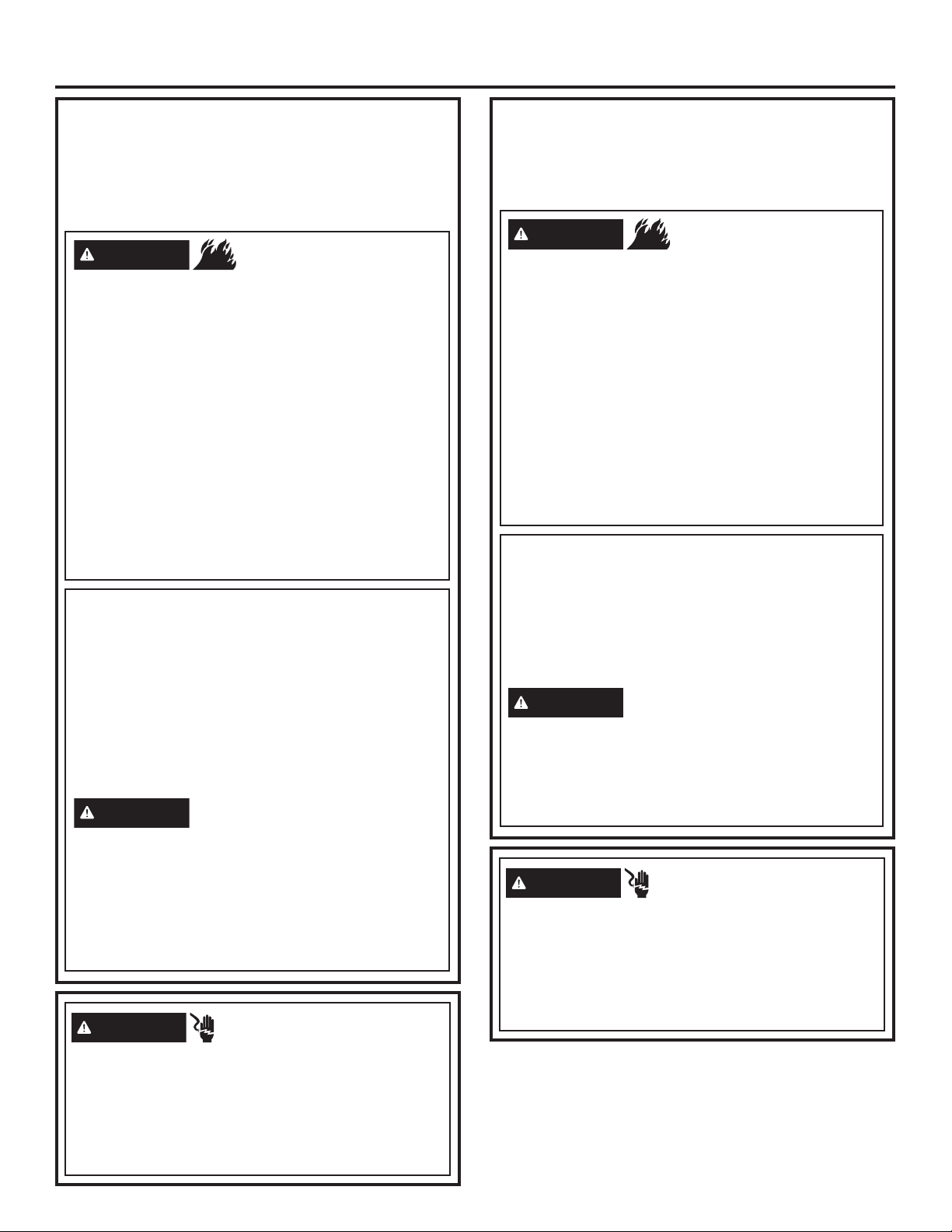
CONNECTING A GAS DRYER (cont.)
GAS REQUIREMENTS
WARNING
• Use a new CSA International approved flexible
gas supply line. Never reuse old flexible
connectors.
• Install an individual manual shut-off valve
within 6ft. of the dryer in accordance with the
National Fuel Gas Code, ANSI Z223.1/NFPA
54.
• Securely tighten all gas connections.
• If connected to LP gas, have a qualified
person make sure gas pressure DOES NOT
exceed 13” water column.
• Examples of a qualified person include:
licensed heating personnel, authorized gas
company personnel, and authorized service
personnel.
• Failure to do so can result in death,
explosion, or fire.
• The installation must conform with local
codes, or in the absence of local codes, with
the National Fuel Gas Code, ANSI Z223.1/
NFPA 54, or the Natural Gas and Propane
Installation Code, CSA B149.1.
- Explosion Hazard
GAS SUPPLY
• A 1/8” National Pipe Taper thread plugged
tapping, accessible for test gauge connection,
must be installed immediately upstream of the
gas supply connection to the dryer. Contact your
local gas utility should you have questions on the
installation of the plugged tapping.
• Supply line is to be 1/2” rigid pipe and equipped
with an accessible shutoff within 6 feet of, and in
the same room with, the dryer.
• Use pipe thread compound appropriate for
natural or LP gas or use PTFE tape.
• Connect flexible metal connector to dryer and
gas supply.
WARNING
FOR USE WITH NATURAL GAS ONLY
Dryer as produced by manufacturer is to be used
only with a natural gas supply. A manufacturersupplied conversion kit is required to convert this
dryer for propane gas supply. Use propane
conversion kit WE25M87
made by properly trained and qualified personnel
in accordance with local codes and ordinances.
- Fire Hazard
gas
. Conversion must be
DRYER GAS SUPPLY CONNECTION
1-5/8”
5-3/4”
NOTE: Add to vertical dimension the
GLVWDQFHEHWZHHQFDELQHWERWWRPWRÀRRU
You must use with this dryer a flexible metal connector
(listed connector ANSI Z21.24 / CSA 6.10). The length
of the connect shall not exceed 4 ft.
49-3000206 Rev 1 17
3/8” NPT MALE
THREAD GAS
SUPPLY
ADJUSTING FOR ELEVATION
• Gas clothes dryers input ratings are based on
sea level operation and need not be adjusted
for operation at or below 2000 ft. elevation. For
operation at elevations above 2000 ft., input
ratings should be reduced at a rate of 4 percent
for each 1000 ft. above sea level.
• Installation must conform to local codes and
ordinances or, in their absence, the NATIONAL
FUEL GAS CODE, ANSI Z223.
Page 18
Installation Instructions
CONNECTING A GAS DRYER (cont.)
CONNECTING THE DRYER TO
THE GAS SUPPLY
Install a female 3/8” NPT elbow at the end of
A
the dryer gas inlet.
Install a 3/8” flare union adapter to the female
elbow.
IMPORTANT: Use a pipe wrench to securely
hold on to the end of the dryer gas inlet to
prevent twisting the inlet.
NOTE: Apply pipe compound or PTFE tape to
the threads of the adapter and dryer gas inlet.
New Metal
Flexible Gas
Line Connector
Adapter
Elbow
Items not supplied
Attach the flexible metal gas line connector to
B
3/8” NPT
the adapter.
Adapter
1/8” NPT
Pipe Plug for
Checking Gas
Inlet Pressure
Shut-Off Valve
Pipe size at
least 1/2”
CONNECTING THE DRYER TO
THE GAS SUPPLY (cont.)
Install a 1/8” NPT plugged tapping to the
D
dryer gas line shut-off valve for checking gas
inlet pressure.
Install a flare union adapter to the plugged
tapping.
NOTE: Apply pipe compound or PTFE tape
to the threads of the adapter and plugged
tapping.
Apply pipe compound
or PTFE tape to all
male threads.
Shut-Off
Valve
Tighten all connections, using two adjustable
E
wrenches. Do not overtighten.
Plugged
Tapping
Apply pipe compound to the
adapter and dryer gas inlet.
Tighten the flexible gas line connection, using
C
two adjustable wrenches.
Open the gas shut-off valve.
F
18 49-3000206 Rev 1
Page 19
Installation Instructions
CONNECTING A GAS DRYER (cont.)
TEST FOR LEAKS
Never use an open flame to test for gas leaks.
Check all connections for leaks with soapy solution or
equivalent.
Apply a soap solution. The leak test solution must not
contain ammonia, which could cause damage to the
brass fittings.
If leaks are found, close the valve, retighten the joint
and repeat the soap test.
Open Gas
Valve
ELECTRICAL CONNECTION
INFORMATION FOR GAS DRYERS
WARNING
Plug into a grounded 3 prong outlet.
DO NOT remove ground prong.
DO NOT use an adapter.
DO NOT use an extension cord.
Failure to do so can result in death, fire or
electrical shock.
• Circuit – Individual properly polarized and grounded
15 or 20 amp circuit breaker or time-delay fuse.
• Power Supply – 2-wire plus ground, 120 Volt, single
phase, 60 Hz, alternating current.
• Outlet Receptacle – Properly grounded 3-prong
receptacle to be located
so the power cord is
accessible when the dryer
is in an installed position.
If a 2-prong receptacle is
present, it is the owner’s
responsibility to have a
licensed electrician replace
it with a properly grounded 3-prong grounding type
receptacle.
- Electrical Shock Hazard
Ensure proper
ground exists
before use.
ELECTRICAL CONNECTION
INFORMATION FOR GAS DRYERS
(cont.)
• Dryer must be electrically grounded in accordance
with local codes and ordinances, or in the absence
of local codes, with the latest edition of the
NATIONAL ELECTRICAL CODE, ANSI/NFPA
NO. 70 or CANADIAN ELECTRICAL CODE, CSA
C22.1. Check with a licensed electrician if you are
not sure that the dryer is properly grounded.
GROUNDING INSTRUCTIONS
This dryer must be grounded. In the event of a
malfunction or breakdown, grounding will reduce
the risk of electric shock by providing a path of
least resistance for electric current. This dryer
uses a cord having an equipment-grounding
conductor and a grounding plug. The plug must
be plugged into an appropriate outlet that is
properly installed and grounded in accordance
with all local codes and ordinances.
WARNING
can result in a risk of electric shock. Check with a
qualified electrician, or service representative or
personnel, if you are in doubt as to whether the
appliance is properly grounded. DO NOT modify
the plug on the power supply cord. If it will not
fit the outlet, have a proper outlet installed by a
qualified electrician.
SAVE THESE INSTRUCTIONS
• If required by local codes, an external 18 gauge or
larger copper ground wire (not provided) may be
added. Attach to dryer cabinet with a #8-18 x ½”
sheet metal screw (available at any hardware store)
to rear of dryer as illustrated.
Ground
Screw
Improper connection of the
equipment-grounding conductor
49-3000206 Rev 1 19
Page 20
Installation Instructions
CONNECTING AN ELECTRIC DRYER
(Skip for gas dryers and if your dryer already has a power cord attached)
TOOLS YOU WILL NEED
Slip-joint pliers
Flat-blade
screwdriver
Phillips
screwdriver
Level
MATERIALS YOU WILL NEED
Ŷ
4” dia. metal elbow
Ŷ
Metal strain relief clamp
(UL recognized)
Ŷ
4” Duct clamps (2) or
4” spring clamps (2)
Ŷ
Gloves
Ŷ
Exhaust hood
Ŷ
Duct tape
Before making the electrical connection, turn off the
circuit breaker(s) or remove the dryer’s circuit fuse(s) at
the electrical box. Be sure the dryer cord is unplugged
from the wall. NEVER LEAVE THE ACCESS COVER
OFF THE TERMINAL BLOCK.
WARNING
Disconnect power supply before servicing.
Replace all parts and panels before operating.
Failure to do so can result in death or electrical shock.
- Electrical Shock Hazard
Ŷ
Safety glasses
Ŷ
4” dia. metal duct
(recommended)
Ŷ
4” dia., UL-listed
flexible metal duct
(if needed)
Ŷ
Access Panel
(Kit WE16X29317)
(if needed)
Ŷ
Dryer power cord kit
(not provided with
dryer)
UL rated 120/240V,
30A with 3 or 4 prongs.
Identify the plug type
as per the house
receptacle before
purchasing line cord.
Stacking installations
may require a power
cord up to 6 feet in
length.
POWER CORDS
GE Appliances strongly recommends the use of
factory specified parts. Select the power cord to fit your
installation requirements.
Part Number Type Length Amperage
WX9X2 3-Prong 4 Feet 30
WX9X3 3-Prong 5 Feet 30
WX9X4 3-Prong 6 Feet 30
WX9X18 4-Prong 4 Feet 30
WX9X19 4-Prong 5 Feet 30
WX9X20 4-Prong 6 Feet 30
Order on-line at GEApplianceparts.com today,
24 hours a day or by phone at 877.959.8688 during
normal business hours. In Canada, visit your local
GE Appliances parts distributor or call 800.661.1616
GEAppliances.ca/en/products/parts-filters-accessories.
or
20 49-3000206 Rev 1
Page 21
Installation Instructions
ELECTRICAL CONNECTION
INFORMATION FOR ELECTRIC
DRYERS
For electrical connections using a
power cord:
WARNING
Use a new UL-listed 240V 30 amp dryer power supply
cord with closed ring terminals or spade terminals with
upturned ends.
Use a UL-listed strain relief.
Disconnect power before making electrical connections.
Connect neutral wire (white or center wire) to center
terminal.
Ground wire (green or bare wire) must be connected to
green ground connector.
Connect remaining two supply wires to remaining two
terminals.
Securely tighten all electrical connections.
Replace the terminal block cover.
Failure to do so can result in death, fire or electrical shock.
- Fire Hazard
GROUNDING INSTRUCTIONS
For a grounded, cord-connected dryer: This dryer
must be grounded. In the event of a malfunction or
breakdown, grounding will reduce the risk of electric
shock by providing a path of least resistance for
electric current. This dryer uses a cord having an
equipment-grounding conductor and a grounding
plug. The plug must be plugged into an appropriate
outlet that is properly installed and grounded in
accordance with all local codes and ordinances.
WARNING
result in a risk of electric shock. Check with a qualified
electrician, or service representative or personnel, if
you are in doubt as to whether the appliance is properly
grounded. DO NOT modify the plug on the power supply
cord. If it will not fit the outlet, have a proper outlet
installed by a qualified electrician.
SAVE THESE INSTRUCTIONS
WARNING
Improper connection of the
equipment-grounding conductor can
- Electrical Shock Hazard
ELECTRICAL CONNECTION
INFORMATION FOR ELECTRIC
DRYERS
For direct wire connections:
WARNING
Use 10 gauge copper wire.
Use a UL-listed strain relief.
Disconnect power before making electrical connections.
Connect neutral wire (white or center wire) to center
terminal.
Ground wire (green or bare wire) must be connected to
green ground connector.
Connect remaining two supply wires to remaining two
terminals.
Securely tighten all electrical connections.
Replace the terminal block cover.
Failure to do so can result in death, fire or electrical shock.
- Fire Hazard
GROUNDING INSTRUCTIONS
For a permanently connected dryer: This dryer
must be connected to a grounded metal, permanent
wiring system, or an equipment-grounding conductor
must be run with the circuit conductors and
connected to the equipment-grounding terminal on
the appliance.
WARNING
result in a risk of electric shock. Check with a qualified
electrician, or service representative or personnel, if
you are in doubt as to whether the appliance is properly
grounded.
SAVE THESE INSTRUCTIONS
WARNING
TO PREVENT ELECTRIC SHOCK, DISCONNECT
POWER BEFORE SERVICING.
This dryer should be connected to an individual branch
circuit with 10 gauge copper wire minimum through a
30 amp fuse or circuit breaker. DO NOT fuse neutral.
Use copper conductors only.
Improper connection of the
equipment-grounding conductor can
- Electrical Shock Hazard
TO PREVENT ELECTRIC SHOCK, DISCONNECT
POWER BEFORE SERVICING.
This dryer should be connected to an individual branch
circuit with 10 gauge copper wire minimum through a
30 amp fuse or circuit breaker. DO NOT fuse neutral.
Use copper conductors only.
49-3000206 Rev 1 21
Page 22
Installation Instructions
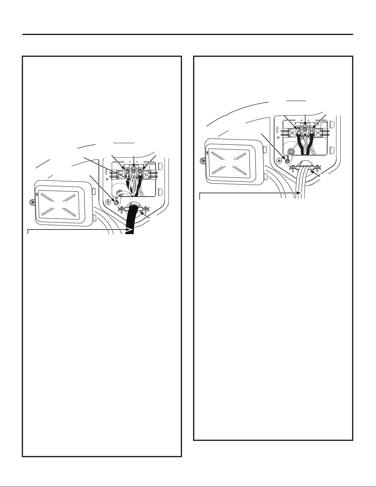
CONNECTING AN ELECTRIC DRYER (cont.)
CONNECTING DRYER USING
4-WIRE CONNECTION (MUST
BE USED FOR MOBILE HOME
INSTALLATION)
NOTE: Since January 1, 1996, the National Electrical
Code requires that new constructions use a 4-wire
connection to an electric dryer. A 4-wire cord must
also be used where local codes do not permit grounding
through the neutral. 3-wire connection is NOT for use
on new construction.
Black
Dryer’s White Strap
Looped to Neutral (N)
Green wire from
power cord
Cover
4 #10 AWG minimum copper conductors or 120/240V 30A
power supply cord kit marked for use with dryers and provided
with closed loop or spade terminals with upturned ends (not
supplied).
1. Turn off the circuit breaker(s) (30 amp) or remove
the dryer’s circuit fuse at the electrical box.
2. Be sure the dryer cord is unplugged from the wall
receptacle.
3. Remove the power cord cover located at the lower
back.
4. Remove green ground screw and retain for use
in Step 7. Leave one end of the short white strap
loose until Step 6. Remove center screw (marked
N) in terminal block.
5. Place the UL-recognized metal strain relief clamp
to power cord entry hole. Bring power cord through
strain relief clamp.
6. Connect power cord as follows:
A. Connect the 2 hot lines to the outer screws of the
terminal block (marked L1 and L2).
B. Connect the neutral (white) line and the loose
end of the short white strap to the center of the
terminal block (marked N).
7. Attach ground wire of power cord with the green
ground screw (hole to left of strain relief clamp).
Tighten all terminal block screws (3) securely.
8. Properly secure power cord to strain relief clamp.
9. Reinstall the cover.
or Red
Wire
White
Wire
L1 N L2
NEVER LEAVE THE COVER OFF OF THE
TERMINAL BLOCK.
Black
or Red
Wire
Metal Strain
Relief
Clamp UL
CONNECTING DRYER USING
3-WIRE CONNECTION
If required, by local code, install external ground (not
provided) to grounded metal, cold water pipe, or other
established ground determined by a qualified electrician.
Black
or Red
Wire
Ground
White Strap
Cover
3 #10 AWG minimum copper conductors or 120/240V 30A
power supply cord kit marked for use with dryers and provided
with closed loop or spade terminals with upturned ends (not
supplied).
3-wire Connection
Not for use in Canada.
DO NOT use for Mobile Home Installations.
NOT for use on new construction.
NOT for use on recreational vehicles.
NOT for use in areas where local codes prohibit
grounding through the neutral conduction.
1. Turn off the circuit breaker(s) (30 amp) or remove
the dryer’s circuit fuse at the electrical box.
2. Be sure the dryer cord is unplugged from the wall
receptacle.
3. Remove the power cord cover located at the lower
back.
4. Place the UL-recognized metal strain relief clamp
to power cord entry hole. Bring power cord through
strain relief clamp.
5. Connect power cord as follows:
A. Connect the 2 hot lines to the outer screws of
the terminal block (marked L1 and L2).
B. Connect the neutral (white) line to the center of
the terminal block (marked N).
6. Be sure ground white strap is connected to green
ground screw on cabinet rear. Tighten all terminal
block screws (3) securely.
7. Properly secure power cord to strain relief clamp.
8. Reinstall the cover.
White
Wire
L1 N L2
NEVER LEAVE THE COVER OFF OF THE
TERMINAL BLOCK.
Black
or Red
Wire
Metal Strain
Relief
Clamp UL
22 49-3000206 Rev 1
Page 23
Installation Instructions
EXHAUSTING THE DRYER
WARNING
This dryer MUST be vented to the outdoors.
Use only 4” rigid metal ducting for the home
exhaust duct.
Use only 4" rigid metal, UL-listed flexible
metal, or UL-listed metal foil dryer transition
duct to connect the dryer to the home exhaust.
DO NOT use any plastic to vent the dryer,
this includes the home exhaust duct, dryer
transition duct, or within the dryer.
DO NOT use flexible metal or metal foil ducting
for a home exhaust duct or within the dryer.
DO NOT exhaust into a chimney, kitchen
exhaust, gas vent, wall, ceiling, attic, crawl
space, or concealed space of a building.
DO NOT install a screen in or over the exhaust
duct.
DO NOT install a booster fan in the exhaust duct.
DO NOT use duct longer than specified in the
exhaust length table.
Failure to follow these instructions can result in
death or fire.
TOOLS AND MATERIALS YOU WILL
NEED TO INSTALL EXHAUST DUCT
Ŷ
1/4" Socket & Nut DriverŶ 1/4" Socket & Wrench
Ŷ
Duct tape or
duct clamp
PARTS AVAILABLE FROM
GEAPPLIANCEPARTS.COM OR
LOCAL SERVICE ORGANIZATIONS
WE16X29317 Dryer Venting Kit
PM8X85
WX08X10130 4” Dryer exhaust clamp
Outdoor exhaust hood
- Fire Hazard
Ŷ
Vent hood
CONNECTING THE DRYER TO
HOUSE VENT
RIGID METAL TRANSITION DUCT
• For best drying performance, a rigid metal transition
duct is recommended.
• Rigid metal transition ducts reduce the risk of
crushing and kinking.
UL-LISTED FLEXIBLE METAL CLOTHES
DRYER TRANSITION DUCT
• If rigid metal cannot be used, then UL-listed flexible
metal clothes dryer transition duct (GE Appliances
part – PM08X10085) can be used.
• Never install transition duct in walls, ceilings, floors
or other enclosed spaces.
• Total length of transition duct should not exceed 8’
(2.4 m).
• For many applications, installing elbows at both
the dryer and the wall is highly recommended (see
illustrations in next section). Elbows allow the dryer
to sit close to the wall without kinking and/or crushing
the transition duct, maximizing drying performance.
• Avoid resting the duct on sharp objects.
UL-LISTED FLEXIBLE METAL (FOIL-TYPE)
TRANSITION DUCT
• In special installations, it may be necessary to
connect the dryer to the home exhaust vent
using flexible metal (foil-type) transition duct. UL–
LISTED universal flexible dryer transition duct
(GE Appliances parts – PM8X73 or WX8X73)
may be used ONLY in installations where rigid
metal or flexible metal transition ducting cannot be
used AND where a 4” diameter can be maintained
throughout the entire length of the transition duct.
• In Canada and the United States, only transition
ducts that comply with “UL 2158A STANDARD
FOR CLOTHES DRYER TRANSITION DUCT”
shall be used.
• Avoid resting the duct on sharp objects.
• For best drying performance:
1. Slide one end of the duct over the clothes
dryer outlet pipe.
2. Secure the duct with a clamp.
3. With the dryer in its permanent position,
extend the duct to its full length. Allow 2”
of duct to overlap the exhaust pipe. Cut off
and remove excess duct. Keep the duct as
straight as possible for maximum airflow.
4. Secure the duct to the exhaust pipe with the
other clamp.
49-3000206 Rev 1 23
Page 24
Installation Instructions
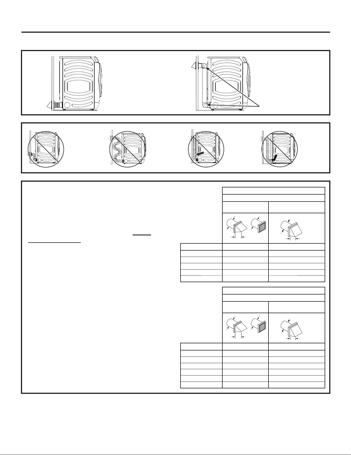
EXHAUSTING THE DRYER (cont.)
• DO cut duct as short
as possible and
install straight into
wall.
• DO NOT bend
or collapse
ducting.
Use elbows
if turns are
necessary.
• DO NOT use
excessive
exhaust
length. Cut
duct as short
as possible.
EXHAUST LENGTH
Using exhaust longer than specified length will:
• Increase the drying times and the energy cost.
• Reduce the dryer life.
• Accumulate lint, creating a potential fire hazard.
The correct exhaust installation is YOUR
RESPONSIBILITY.
Problems due to incorrect installation are not
covered by the warranty.
The MAXIMUM ALLOWABLE length of the exhaust
system depends upon the type of duct, number of turns,
the type of exhaust hood (wall cap) and all conditions
noted on the chart.
• Internal elbows added for side or bottom vent
conversions must be included in the total elbow count.
• Any elbow greater than 45° should be treated as a 90°
elbow; one elbow of 45° or less may be ignored.
• Two 45° elbows will be treated like one 90° elbow.
• For the side exhaust installations, add one 90° elbow to
the chart.
• For every additional 90° elbow, reduce the allowable
vent system length by 10 feet.
• When calculating the total vent system length, you
must add all the straight portions and elbows of the
system (including the transition duct).
• DO use elbows
when turns are
necessary.
Elbows
• DO NOT
set dryer
on duct
installations
4" DIA.
EXHAUST
LENGTH
FOR
NORMAL
• DO NOT
crush duct
against
the wall
4" DIA.
.
RECOMMENDED MAXIMUM LENGTH
Exhaust Hood Types
Recommended
4" DIA.
Use only for short run
VENT
MODELS
No. of 90° Elbows Rigid Metal Rigid Metal
0 90 Feet 60 Feet
1 60 Feet 45 Feet
2 45 Feet 35 Feet
3 35 Feet 25 Feet
4 25 Feet 15 Feet
EXHAUST
LENGTH
FOR
LONG
4"
RECOMMENDED MAXIMUM LENGTH
Exhaust Hood Types
Recommended
4" DIA.
4" DIA.
Use only for short run
installations
4" DIA.
2-1/2"
VENT
MODELS
No. of 90° Elbows Rigid Metal Rigid Metal
0 200 Feet 175 Feet
1 185 Feet 165 Feet
2 175 Feet 155 Feet
3 165 Feet 145 Feet
4 155 Feet 135 Feet
5 145 Feet 125 Feet
4"
2-1/2"
.
24 49-3000206 Rev 1
Page 25

Installation Instructions
EXHAUSTING THE DRYER (cont.)
EXHAUST SYSTEM CHECKLIST
HOOD OR WALL CAP
• Terminate in a manner to prevent back drafts or entry of
birds or other wildlife.
• Termination should present minimal resistance to
the exhaust airflow and should require little or no
maintenance to prevent clogging.
• Wall caps must be installed at least 12” above ground
level or any other obstruction with the opening pointed
down.
SEPARATION OF TURNS
• For best performance, separate all turns by at least
4 ft. of straight duct, including distance between
last turn and dampened exhaust hood (wall cap).
SEALING OF JOINTS
• All joints should be tight to avoid leaks. The male end
of each section of duct must point away from the dryer.
• Duct joints should be made air- and moisture-tight
by wrapping the overlapped joints with duct tape or
aluminum tape.
• Do not assemble ductwork with any fasteners that
extend into the duct. These fasteners can accumulate
lint, creating a potential fire hazard.
• Horizontal runs should slope down towards the
outdoors 1/4” per foot.
• Provide an access for inspection and cleaning of
the exhaust system, especially at turns and joints.
Exhaust system shall be inspected and cleaned at
least once a year.
INSULATION
• Ductwork that runs through an unheated area or is
near air conditioning should be insulated to reduce
condensation and lint build-up.
STANDARD REAR EXHAUST
We recommend that you install your dryer before
installing your washer. This will permit direct
access for easier exhaust connection.
Slide the end of the exhaust duct on the back of the
dryer and secure with duct tape or a hose clamp.
Duct
NOTE: We strongly recommend using rigid metal
exhaust duct. However, if flexible ducting is used it
must be UL-Listed metal, not plastic.
• For straight line installation, connect the dryer
exhaust to the external exhaust hood using duct
tape or clamp.
Wall Side
Duct Tape
Dryer
Side
RECOMMENDED CONFIGURATION
TO MINIMIZE EXHAUST BLOCKAGE
Using duct elbows will prevent duct kinking and
collapsing.
BEFORE YOU BEGIN
• Remove and discard existing plastic or metal foil
duct and replace with UL-listed duct.
• Remove any lint from the wall exhaust opening.
Wall
Internal
Duct
Opening
Check that exhaust
hood damper
opens and closes
freely.
49-3000206 Rev 1 25
Wall
Transition
Ducting
Page 26

Installation Instructions
EXHAUSTING THE DRYER (cont.)
SIDE VENTING
WARNING
Disconnect dryer from electrical supply.
Wear gloves and arm guards.
Close the back opening with the access
panel included in kit WE16X29317.
Failure to do so may result in fire, electrical
shock or lacerations.
• Remove the 4 screws that secure the access panel
and save. Remove the access panel.
Remove
4 screws
and save
• Detach and remove the right or left side knockout
as desired. Remove the screw that secures the
dryer exhaust duct and save. Pull the exhaust duct
out of the dryer.
Right
knockout
- Fire Hazard
Access Panel
SIDE VENTING (cont.)
• Insert and connect the elbow/exhaust duct assembly
to the blower housing and orient the elbow for either
left or right venting.
Left Venting
Right Venting
• Locate the bracket from the kit.
• Remove the adhesive liner from the bottom of the
bracket and position it behind the elbow duct tab.
• Press down firmly to secure the bracket to the bottom
of the dryer.
Exhaust Duct
Remove screw and save
• Locate the 12-1/2” exhaust duct and elbow duct
from the kit and assemble together. Apply duct tape
around the joint to eliminate leaks between ducts.
12-1/2"
Left Knockout
Elbow Duct Tab
Bracket
Saved Screw
• Using one of the screws from earlier, secure the
elbow duct tab to the bracket.
26 49-3000206 Rev 1
Page 27

Installation Instructions
EXHAUSTING THE DRYER (cont.)
SIDE VENTING (cont.)
For LEFT venting:
• Locate the 15-1/2” exhaust duct from the kit.
• Insert exhaust duct through knockout opening on
the LEFT side of dryer.
• Assemble exhaust duct to elbow duct.
• Wrap the joint with duct tape to avoid air leaks.
Venting
For RIGHT venting:
• Locate the 9-1/2” exhaust duct from the kit.
• Insert exhaust duct through knockout opening on
the RIGHT side of dryer.
• Assemble exhaust duct to elbow duct.
• Wrap the joint with duct tape to avoid air leaks.
Right
Venting
Left
BOTTOM VENTING
Dryer Exhaust to the bottom of cabinet for Gas
and Electric models WITHOUT Built-In Pedestal™.
WARNING
Disconnect dryer from electrical supply.
Wear gloves and arm guards.
Close the back opening with the access
panel included in kit WE16X29317.
Failure to do so may result in fire, electrical
shock or lacerations.
• Remove the 4 screws that secure the access panel
and save. Remove the access panel.
Remove
4 screws
and save
• Remove the screw that secures the dryer exhaust
duct and save. Pull the exhaust duct out of the dryer.
- Fire Hazard
Access Panel
• Install the new access panel from the kit.
• Secure access panel with 4 screws saved from
earlier.
NEVER LEAVE THE BACK OPENING WITHOUT
THE ACCESS PANEL.
Exhaust Duct
Remove screw and save
• Detach and remove the bottom knockout.
Botom Knockout
49-3000206 Rev 1 27
Page 28

Installation Instructions
EXHAUSTING THE DRYER (cont.)
BOTTOM VENTING (cont.) BOTTOM VENTING (cont.)
• Locate the 12-1/2” exhaust duct and elbow duct
from the kit and assemble together. Apply duct tape
around the joint to eliminate leaks between ducts.
12-1/2"
• Insert and connect the elbow/exhaust duct
assembly to the blower housing and insert the
elbow through the bottom knockout.
• Install the new access panel from the kit.
• Secure access panel with 4 screws saved from
earlier.
NEVER LEAVE THE BACK OPENING WITHOUT
THE ACCESS PANEL.
28 49-3000206 Rev 1
Page 29

FINAL SETUP
Installation Instructions
1
LEVEL THE DRYER
Stand the dryer upright near the final location and
adjust the four leveling legs at the corners to ensure
that the dryer is level from side to side and front to
rear.
Lower
2
PLUG DRYER IN
NOTE: Stacking installations may require a power
cord up to 6 feet in length.
Raise
Ensure proper
ground exists
before use.
3
DRYER START-UP
Press the Power pad.
NOTE: If the dryer has been exposed to temperatures
below freezing for an extended period of time, allow it to
warm up before pressing Power. Otherwise, the display
will not come on.
The dryer is now ready for use.
WARNING
Disconnect power supply before servicing.
Replace all parts and panels before operating.
Failure to do so can result in death or electrical
shock.
WARNING
Certain internal parts are intentionally not grounded
and may present a risk of electric shock only during
servicing.
Service personnel – DO NOT contact the following
parts while the appliance is energized: water
valve, door switch, electronic board, igniter,
thermostats, flame detector.
- Electrical Shock Hazard
- Shock Hazard
49-3000206 Rev 1 29
Page 30

Installation Instructions
REVERSING THE DOOR SWING (Optional)
BEFORE YOU START
Unplug the dryer from its electrical outlet.
TOOLS YOU WILL NEED
Phillips-head screwdriver T-25 torx driver 1/4” nut driver
IMPORTANT NOTES
• Handle parts carefully to avoid scratching paint.
• Provide a non-scratching work surface for the door.
• Set screws down by their related parts to avoid using
them in the wrong places.
• Once you begin, do not move the cabinet until
door-swing reversal is completed.
• These instructions are for changing the hinges from the
right side to the left side—if you ever want to switch them
back to the right side, follow these same instructions and
reverse all references to the left and right.
1
REMOVE THE STRIKE PLATE
AND DOOR ASSEMBLY
• Open the dryer door.
• Remove the two screws from the strike plate using
a T-25 torx driver.
• Remove the strike plate and set it aside.
• While supporting the door, remove the two screws
from the hinge in the dryer face using a 1/4” nut driver.
• Lift the door assembly to remove it from the dryer
face and set it aside on a protective surface.
Remove Strike
Plate and Screws
Hinge and Door
Assembly
Hold the Door and
Remove Hinge Screws
from the Dryer
2
REMOVE THE INNER DOOR
• Remove the 14 screws from the inner door frame
using a Phillips-head screwdriver and set them aside.
• Remove the inner door frame from the outer door.
NOTE: Do not remove the gasket from the inner door
frame.
30 49-3000206 Rev 1
Page 31

Installation Instructions
REVERSING THE DOOR SWING (Optional)
3
REMOVE, ROTATE AND REPLACE
THE HANDLE AND HINGE INTO
THE OPPOSITE SIDES
• Lift the handle and the hinge out of the door pockets.
NOTE: Make sure the latch remains seated inside the
handle. If it moves or falls out, seat it back into place.
4
REPLACE THE INNER DOOR
• Replace the inner door frame into the outer door.
Replace the 14 screws into the inner door, using a
•
Phillips-head screwdriver, securing it to the outer door.
NOTE: Make sure the gasket is properly seated on
the inner door frame when replaced.
• Rotate the handle and hinge, and replace them
back into the pockets on the opposite sides.
5
REPLACE THE STRIKE PLATE
AND DOOR ASSEMBLY
• On the opposite side from where removed, replace
the strike plate with its two screws using a T-25 torx
driver.
• Lift the door assembly into place and secure it onto
the dryer face with its two screws using a 1/4” nut driver.
• Close the dryer door.
NOTE: Make sure the door opens and closes
correctly. If not, repeat all steps making sure the
gasket, all parts, and screws are securely seated.
Replace Strike
Plate and Screws
Hold the Door and
Replace Hinge Screws
into the Dryer
49-3000206 Rev 1 31
Page 32

Installation Instructions
STACKING THE WASHER AND DRYER (if desired)
If you are planning to stack the washer and dryer, order Stacking Kit number GFA28KITN to be used for this dryer.
Kit sold separately.
If you have any questions, call GE Appliances at 800.432.2737 or visit our Website at: GEAppliances.com
In Canada, call 800.561.3344 or visit www.GEAppliances.ca
BEFORE YOU BEGIN
Read these instructions completely and carefully.
• IMPORTANT – Save these instructions for
local electrical inspector’s use.
• IMPORTANT – Observe all governing
codes and ordinances.
• Note to Installer – Be sure to leave these
instructions with the Consumer.
• Note to Consumer – Keep these instructions for
future reference.
• Installation must be performed by a qualified
installer.
• Proper installation is the responsibility of the installer.
Stack dryer only on washer. Do not stack washer on
dryer, washer on washer or dryer on dryer.
Do not modify this installation kit. Any modification will
void the product Warranty.
WARNING
result in serious injury or death.
WARNING
• Use two or more people to install dryer.
• Avoid tipping and rupture of utility services.
• Dryer must be securely attached to the washer.
• DO NOT place the washer on top of the dryer.
Failure to do so may result in serious injury,
death, or property damage.
Mobile Home or Manufactured Home Installation –
Stacking of a gas dryer is not permitted in a mobile
home or manufactured home.
INSTALLATION PREPARATION
Remove the packaging.
Flatten the product carton to use as a pad to lay
the dryer down on its back or side. Continue using
the carton to protect the finished floor in front of the
installation location.
Disconnect power before
installing. Failure to do so could
- Excessive Weight
Hazard
REQUIREMENTS FOR ALCOVE OR
CLOSET INSTALLATION
WARNING
Keep flammable materials and vapors, such as
gasoline,
away from dryer.
Place dryer at least 18” (46 cm) above the floor
for a garage installation.
Failure to do so can result in death, explosion, or fire.
• The dryer MUST be vented to the outdoors.
• Minimum clearance between dryer cabinet and
adjacent walls or other surfaces is:
0” either side*
0” front
0” rear
0” top
• The rear of the dryer should face a wall.
• Consideration must be given to provide adequate
clearance for installation and service.
• Closet doors must be louvered or otherwise ventilated
and have at least 60 square inches of open area. If the
closet contains both a washer and a dryer, doors must
contain a minimum of 120 square inches of open area.
NOTE: WHEN THE EXHAUST DUCT IS LOCATED AT
THE REAR OF THE DRYER, THE CONFIGURATION
OF THE DUCTING MAY REQUIRE GREATER
CLEARANCE.
Gas Dryers Only:
• No other fuel burning appliance shall be installed in
the same closet as a gas dryer.
• The dryer must be disconnected from the gas
supply piping during pressure testing at pressures
greater than 1/2 psi (3.5 kPa).
• A 1/8 inch NPT minimum plugged tapping,
accessible for test gauge connection, must be
installed immediately upstream of the gas supply
connection to the dryer.
- Explosion Hazard
MINIMUM CLEARANCE OTHER
THAN ALCOVE OR CLOSET
INSTALLATION
Minimum clearance to combustible surfaces and for
air opening are: 0” both sides*, 0” rear and 0” top.
The rear of the dryer should face a wall.
Consideration must be given to provide adequate
clearance for installation and service.
For improved performance, a 1/2” clearance is suggested on either side.
*
32 49-3000206 Rev 1
Page 33

Installation Instructions
STACKING THE WASHER AND DRYER
TOOLS YOU WILL NEED
Ŷ
Phillips screwdriver
Ŷ
Open-ended wrench
Ŷ
Pliers
Ŷ
Gloves
Ŷ
Level
CONTENTS
Ŷ
Bracket 32
(2)
Ŷ
Spacer (2)
1
REMOVE THE DRYER LEVELING
Ŷ
Bracket 34
(2)
Ŷ
#8 1/2" Screws
(16)
LEGS
A. Carefully lay the dryer on its back or side. Use the
packing material so you don’t scratch the finish on
the dryer.
2
INSTALL SPACERS TO THE
DRYER BOTTOM
Locate a spacer on the bottom side with its holes over
the leveling leg holes. Attach spacer using 2 screws.
Attach the second spacer on the other bottom side
using 2 screws. NOTE: The arrows on the spacers
should point to the outside.
Make sure the arrows on the spacer point to the outside.
Attach spacer using 2 screws
Front Back
(Optional Kit GFA28KITN)
B. Use an open-end wrench or pliers to remove the
dryer leveling legs. NOTE: Retain the leveling legs
for future use.
Back out and
remove all 4
leveling legs
Attach spacer using 2 screws
Make sure the arrows on the spacer point to the outside.
49-3000206 Rev 1 33
Page 34

Installation Instructions
STACKING THE WASHER AND DRYER
3
INSTALL THE APPROPRIATE
BRACKETS TO THE WASHER
Washer Depth Dryer Depth Bracket Number
32" 32" 32
34" 32" 34
Select the appropriate brackets for your model sizes.
Using the outside holes in the bracket, attach it to the
top left corner of the washer back using 4 screws.
Repeat on the top right corner of the washer back.
32 Brackets for 32" Washer & Dryer Combinations:
Attach
brackets to
washer using
4 screws on
each side
4
PREPARE THE WASHER AND
DRYER
A. Place the washer in the approximate final
installation location.
B. Make sure the washer is level. Refer to the washer
Installation Instructions for details.
C. Upright the dryer.
D. Reverse the washer and dryer door swings, if
desired, before stacking the dryer on the washer.
See the washer and dryer Installation Instructions
for details.
(Optional Kit GFA28KITN)
Install brackets flush at
washers edges
Do not install brackets
overhanging washers edges
OR
34 Brackets for 34" Washer & 32" Dryer Combinations:
Attach
brackets to
washer using
4 screws on
each side
Install brackets flush at
washers edges
Do not install brackets
overhanging washers edges
34 49-3000206 Rev 1
Page 35

Installation Instructions
STACKING THE WASHER AND DRYER
5
INSTALL THE DRYER AND THE
BRACKET ON THE WASHER
WARNING
• Use two or more people to install dryer.
• Avoid tipping and rupture of utility services.
• Dryer must be securely attached to the washer.
• DO NOT place the washer on top of the dryer.
Failure to do so may result in serious injury,
death, or property damage.
A. Lift the dryer onto the top of the washer.
Be sure to lift the dryer high enough to clear the
washer control panel.
Be careful not to scratch the top of the washer with
the spacers. Protect the washer control panel with
cardboard or other protection.
B. Align the holes in the back of the dryer with the
holes in the bracket sticking up from the washer.
Attach both brackets to the dryer with 2 screws on
each side.
- Excessive Weight
Hazard
6
FINALIZE THE INSTALLATION
CAUTION
Do not push on the dryer once
installed to top of the washer.
Pushing on the dryer may result in pinched
fingers.
A. Refer to the washer Installation Instructions to
complete the washer installation.
B. Refer to the dryer Installation Instructions to
complete the dryer installation.
C. Carefully slide or walk the stacked washer and
dryer into place. Use felt pads or other sliding
device to assist moving and to protect flooring.
D. Verify the units are level. Make adjustments to
the washer feet if necessary to level. It is always
best to set the washer feet to the minimum height
necessary to level the washer and dryer properly.
(Optional Kit GFA28KITN)
Dryer
32 Brackets for 32" Washer & Dryer Combinations:
Attach
brackets
to dryer
using 2
screws on
each side
OR
34 Brackets for 34" Washer & 32" Dryer Combinations:
Attach
brackets
to dryer
using 2
screws on
each side
Place
hands
here
Place
hands
here
Washer
49-3000206 Rev 1 35
Page 36

Troubleshooting Tips... Before you call for service
Problem Possible Cause What To Do
Dryer shakes or
makes noise
Clothes take
too long to dry
TROUBLESHOOTING TIPS
The Dry dryness
level was
chosen but load
is still damp
Dryer doesn’t
start
No numbers
displayed
during cycle,
only lights
Time Remaining
jumped to a
lower number
Cannot make a
selection and
the dryer beeps
twice
Dryer is running
but 00 is
displayed in
Time Remaining
“Check Vent”
light is on
Some shaking/noise is normal.
Dryer may be sitting unevenly.
Improper or obstructed
ducting
Improper sorting Separate heavy items from lightweight items (generally, a
Large loads of heavy fabrics
(like beach towels)
Controls improperly set Match control settings to the load you are drying.
Lint filter is full Clean lint filter before every load.
Blown fuses or tripped
circuit breaker
Overloading/combining loads Do not put more than one washer load in the dryer at a time.
Underloading If you are drying only one or two items, add a few items to ensure
ecoDry is enabled The ecoDry feature is designed to operate your dryer in the
Load consists of a mixture of
heavy and light fabrics
Exhaust system is blocked Inspect and clean exhaust system.
Control panel is “asleep” This is normal. Press Power to activate the control panel.
Dryer is unplugged Make sure the dryer plug is pushed completely into the outlet.
Fuse is blown/circuit breaker
is tripped
Dryer was accidentally paused
when starting Delay Dry
Dryer is continuously
monitoring the amount of
moisture in the clothes
The estimated time may
change when a smaller load
than usual is drying
The dryness Level, Temp or
option that you are trying to
select is incompatible with
the chosen dry cycle
The Wrinkle Care option
was chosen
Lint filter is full Clean lint filter, dry a load on an automatic cycle and verify that
Improper or obstructed
ducting
Exhaust system is blocked Inspect and clean the exhaust system.
Move dryer to an even floor space, or adjust leveling legs as
necessary until even.
Check the Installation Instructions to make sure the dryer
venting is correct.
Make sure ducting is clean, free of kinks and unobstructed.
Check to see if outside wall damper operates easily.
well-sorted washer load is a well-sorted dryer load).
Large, heavy fabrics contain more moisture and take longer to dry.
Separate large, heavy fabrics into smaller loads to speed drying time.
Replace fuses or reset circuit breakers. NOTE: Some electric
dryers use 2 fuses/breakers, make sure both are operating.
proper tumbling.
most energy efficient mode, which is not always the fastest
mode. In some instances, dry times may be extended to
reduce overall energy usage for the cycle.
When combining heavy and light fabrics in a load, choose
More Dry.
Check the building’s fuse/circuit breaker box and replace fuse
or reset breaker. NOTE: Some electric dryers use two fuses/
breakers, make sure both are operating.
If the light on the Start/Pause pad is flashing, the dryer is paused.
Press Start/Pause to restart the countdown.
This is normal. When the dryer senses a low level of moisture in
the load, the dryer will display the dry time remaining.
This is normal.
This is normal.
This is normal. During extended tumbling, the time remaining is
not displayed. The extended tumbling option lasts approximately
60 minutes.
light turns off.
Check the Installation Instructions to make sure the dryer venting
is correct.
Make sure ducting is clean, free of kinks and unobstructed. Check
to see if outside wall damper operates easily.
Dry a load on an automatic cycle and verify that light turns off.
Dry a load on an automatic cycle and verify that light turns off.
36 49-3000206 Rev 1
Page 37

Troubleshooting Tips... Before you call for service
Problem Possible Causes What To Do
Dryer doesn’t
heat
Inconsistent
drying times
Clothes are still
wet and dryer
shut off after a
short time
Clothes are
wrinkled
Clothes shrink Some fabrics will naturally
Greasy spots
on clothes
Lint on clothes Lint filter is full Clean lint screen before each load.
Fuse is blown/circuit breaker
is tripped; the dryer may
tumble but not heat
Gas service is off (gas
models only)
LP gas supply tank is empty
or there has been a utility
interruption of natural gas
(gas models only)
No heat temperature selected Select another heat setting
Type of heat Drying time will vary according to the type of heat used. If
Type of load and drying
conditions
The door was opened
mid-cycle. The load was then
removed from the dryer and
a new load put in without
selecting a new cycle
Small load When drying 3 items or less, choose QUICK DRY or TIMED DRY.
Load was already dry except
for collars and waistbands
Dryer is not level Move dryer to an even floor space or adjust leveling legs as
Overdrying Select a shorter drying time.
Letting items sit in dryer after
cycle ends
Overloading Separate large loads into smaller ones.
shrink when washed. Others
can be safely washed, but
will shrink in the dryer.
Improper use of fabric
softener
Drying dirty items with clean
ones
Clothes were not completely
clean
Improper sorting Sort lint producers (like chenille) from lint collectors (like corduroy).
Static electricity can attract
lint
Overloading Separate large loads into smaller ones.
Paper, tissue, etc., left in
pockets
Check the building’s fuse/circuit breaker box and replace both
fuses or reset both breakers. Your dryer may tumble if only one
fuse is blown or one breaker tripped. NOTE: Some electric
dryers use 2 fuses/breakers, make sure both are operating.
Make sure gas shutoff at dryer and main shutoff are fully open.
Refill or replace tank. Dryer should heat when utility service is
restored.
you recently changed from an electric to a gas (natural or LP)
dryer, or vice versa, the drying time could be different.
The load size, types of fabric, wetness of clothes and the
length and condition of the exhaust system will affect drying
times.
A dry cycle must be reselected each time a new load is put in.
Choose
waistbands. In the future, when drying a load with collars and
waistbands, choose More Dry.
necessary until even.
Remove items while they still hold a slight amount of moisture.
Select a Less Dry or Damp setting.
Remove items when cycle ends and fold or hang immediately, or
use the Wrinkle Care option.
To avoid shrinkage, follow garment care labels exactly.
Some items may be pressed back into shape after drying.
If you are concerned about shrinkage in a particular
item, do not machine wash or tumble dry it.
Follow directions on fabric softener package.
Use your dryer to dry only clean items. Dirty items can stain clean
items and the dryer.
Sometimes stains which cannot be seen when the clothes are wet
appear after drying. Use proper washing procedures before drying.
See suggestions in this section under Static occurs.
Empty all pockets before laundering clothes.
QUICK DRY or TIMED DRY to dry damp collars and
TROUBLESHOOTING TIPS
49-3000206 Rev 1 37
Page 38

Troubleshooting Tips... Before you call for service
Problem Possible Causes What To Do
Static occurs No fabric softener was used Try a fabric softener.
®
Fabric Conditioner Dryer Sheets have been approved for
Overdrying Try a fabric softener.
Synthetics, permanent press
and blends can cause static
Collars and
waistbands still
wet at end of
cycle
Slight variation
in metallic color
Dryer continues
to tumble after
TROUBLESHOOTING TIPS
display says
Complete
Door is too
foggy to see
clothes during a
steam cycle
Water seen on
inside of door
and top of lint
filter when
opening door
after steam
cycle
Small areas
on clothes are
damp after
steam cycle
Small amount of
water on floor in
front of dryer
Water on floor in
back of dryer
Water drips
from door when
opened after a
Steam Cycle
Cannot see
steam at
beginning of
cycle
Cannot see
steam during
cycle
Garments still
wrinkled after
steam cycle
The dryness monitor senses
that the body of the clothes
is dry
This is normal Due to the metallic properties of paint used for this unique product,
Wrinkle Care was selected Ensure Wrinkle Care option is not selected. For the Steam
Steam condenses on inner
door
Steam condenses on these
surfaces
Steam condenses on inner
drum
Inadequate load size for
steam cycle selected, excess
steam condenses inside
cabinet and leaks out
Loose water hose connection Tighten connection.
Hose missing rubber washer
at connection with valve
Steam condenses on inner
door
Steam released at different
times in the cycle
The steam nozzle might be
clogged with debris from your
water supply
Too many garments Load fewer garments; manually increase time.
Lint filter not clean Clean lint filter
Load is children/infant
garments
Bounce
use in all GE Appliances dryers when used in accordance with the
manufacturer’s instructions.
Adjust setting to Less Dry or Damp.
Try a fabric softener.
Choose QUICK DRY or TIMED DRY to dry damp collars and
waistbands. In the future, when drying a load with collars and
waistbands, choose More Dry.
slight variations of color may occur due to viewing angles and
lighting conditions.
Refresh cycle, Wrinkle Care will automatically be turned on
and cannot be turned off.
This is normal.
This is normal.
If using the STEAM Dewrinkle cycle, manually reduce the cycle
time. If using the STEAM Refresh cycle, add more garments to
the load.
If using the STEAM Dewrinkle cycle, manually reduce the cycle
time. If using the STEAM Refresh cycle, add more garments to
the load.
Install rubber washer provided with hose.
This is normal.
This is normal.
Call GE Appliances at 877.959.8688 to order nozzle
replacement kit WE25M71 or to request a technician to replace
this for you.
Use the Steam Refresh cycle
38 49-3000206 Rev 1
Page 39

GE Appliances Dryer Limited Warranty
GEAppliances.com
All warranty service is provided by our Factory Service Centers, or an authorized Customer Care® technician. To schedule
service online, visit us at GEAppliances.com/service, or call GE Appliances at 800.GE.CARES (800.432.2737). Please
have your serial number and your model number available when calling for service.
Servicing your appliance may require the use of the onboard data port for diagnostics. This gives a GE Appliances factory
service technician the ability to quickly diagnose any issues with your appliance and helps GE Appliances improve its
products by providing GE Appliances with information on your appliance. If you do not want your appliance data to be
sent to GE Appliances, please advise your technician not to submit the data to GE Appliances at the time of service.
For the period of: We will replace:
One year
From the date of the
original purchase
What is not covered:
Ŷ
Service trips to your home to teach you how to use
the product.
Ŷ
Improper installation, delivery or maintenance.
Ŷ
Failure of the product if it is abused, misused, or used for
other than the intended purpose or used commercially.
Ŷ
Replacement of house fuses or resetting of circuit
breakers.
Ŷ
Products which are not defective or broken, or which
are working as described in the Owner’s Manual.
Any part of the dryer which fails due to a defect in materials or workmanship. During
this limited one-year warranty, we will also provide, free of charge, all labor and
related service to replace the defective part.
Ŷ
Damage to the product caused by accident, fire,
floods or acts of God.
Ŷ
Incidental or consequential damage caused by
possible defects with this appliance.
Ŷ
Defects or damage due to operation in freezing
temperatures.
Ŷ
Damage caused after delivery.
Ŷ
Product not accessible to provide required service.
LIMITED WARRANTY
Staple your receipt here. Proof of the original purchase
date is needed to obtain service under the warranty.
EXCLUSION OF IMPLIED WARRANTIES
Your sole and exclusive remedy is product repair as provided in this Limited Warranty. Any implied warranties,
including the implied warranties of merchantability or fitness for a particular purpose, are limited to one year or the
shortest period allowed by law.
This limited warranty is extended to the original purchaser and any succeeding owner for products purchased for home use
within the USA. If the product is located in an area where service by a GE Appliances Authorized Servicer is not available,
you may be responsible for a trip charge or you may be required to bring the product to an Authorized GE Appliances
Service location for service. In Alaska, the limited warranty excludes the cost of shipping or service calls to your home.
Some states do not allow the exclusion or limitation of incidental or consequential damages. This limited warranty
gives you specific legal rights, and you may also have other rights which vary from state to state. To know what your
legal rights are, consult your local or state consumer affairs office or your state’s Attorney General.
Warrantor: GE Appliances, a Haier Company
Louisville, KY 40225
Extended Warranties: Purchase a GE Appliances extended warranty and learn about special discounts that are
available while your warranty is still in effect. You can purchase it online anytime at
GEAppliances.com/extended-warranty
or call 800.626.2224 during normal business hours. GE Appliances Service will still be there after your warranty expires.
49-3000206 Rev 1 39
Page 40

Consumer Support
GE Appliances Website
Have a question or need assistance with your appliance? Try the GE Appliances Website 24 hours a day, any day
of the year! You can also shop for more great GE Appliances products and take advantage of all our on-line support
services designed for your convenience. GEAppliances.com
Register Your Appliance
Register your new appliance on-line at your convenience! Timely product registration will allow for enhanced
communication and prompt service under the terms of your warranty, should the need arise. You may also mail in
the pre-printed registration card included in the packing material. GEAppliances.com/register
Schedule Service
Expert GE Appliances repair service is only one step away from your door. Get on-line and schedule your service at
CONSUMER SUPPORT
your convenience any day of the year. GEAppliances.com/service or call 800.432.2737 during normal business hours.
Extended Warranties
Purchase a GE Appliances extended warranty and learn about special discounts that are available while your
warranty is still in effect. You can purchase it on-line anytime. GE Appliances Services will still be there after your
warranty expires. GEAppliances.com/extended-warranty or call 800.626.2224 during normal business hours.
Remote Connectivity
For assistance with wireless network connectivity (for models with remote enable), visit our website at
GEAppliances.com/connected-home-smart-appliances/ or call 800.220.6899.
Parts and Accessories
Individuals qualified to service their own appliances can have parts or accessories sent directly to their homes
(VISA, MasterCard and Discover cards are accepted). Order on-line today 24 hours every day.
GEApplianceparts.com or by phone at 877.959.8688 during normal business hours.
Instructions contained in this manual cover procedures to be performed by any user. Other servicing
generally should be referred to qualified service personnel. Caution must be exercised, since improper
servicing may cause unsafe operation.
Contact Us
If you are not satisfied with the service you receive from GE Appliances, contact us on our Website with all the
details including your phone number, or write to:
General Manager, Customer Relations | GE Appliances, Appliance Park | Louisville, KY 40225
GEAppliances.com/contact
Printed in USA
40 49-3000206 Rev 1
Page 41

CONSIGNES DE SÉCURITÉ ......3
UTILISATION DE LA SÉCHEUSE
Connectivité WiFi .................... 5
Pour démarrer ....................... 5
Cycles .............................. 7
Réglages ............................ 8
Options ............................. 8
Chargement ..........................10
ENTRETIEN ET NETTOYAGE ... 11
GUIDE DE
L’UTILISATEUR
ET INSTRUCTION
D’INSTALLATION
GFD85
GFD65
GFD55
GFV55
INSTRUCTIONS
D’INSTALLATION ................12
Inversion de l’ouverture de la porte
(Optionnel) ......................... 30
Comment superposer la sécheuse à la
laveuse (Optionnel) ...................32
CONSEILS DE DÉPANNAGE ... 36
GARANTIE LIMITÉE ............ 39
SERVICE À LA CLIENTÈLE .... 40
FRANÇAIS
Inscrivez ici les numéros
de modèle et de série :
Modèle # ________________
Série # __________________
Ces informations figurent sur
l’étiquette située à l’avant de
SÉCHEUSES
GE est une marque déposée de General Electric Company. Fabriqué sous licence de marque.
la sécheuse, derrière la porte.
49-3000206 Rev 1
09-19 GEA
Page 42

NOUS VOUS REMERCIONS D’ACCUEILLIR GE APPLIANCES CHEZ VOUS
Que vous ayez grandi avec GE Appliances ou qu’il s’agisse de votre première acquisition, nous
sommes heureux de vous accueillir dans notre famille.
Nous sommes fiers du savoir-faire, de l’innovation et de l’esthétique qui composent chaque appareil
GE Appliances, et nous pensons que vous le serez aussi. Dans cette optique, nous vous rappelons
que l’enregistrement de votre électroménager vous assure la communication de renseignements
importants sur le produit et la garantie lorsque vous en avez besoin.
Enregistrez votre électroménager GE en ligne dès maintenant. Des sites Web et des numéros de
téléphone utiles figurent dans la section Soutien au consommateur de ce manuel d’utilisation. Vous
pouvez aussi poster la fiche de garantie préimprimée incluse dans l’emballage.
2 49-3000206 Rev 1
Page 43

CONSIGNES DE SÉCURITÉ IMPORTANTES
LIRE TOUTES LES CONSIGNES AVANT D’UTILISER L’APPAREIL
CONSIGNES DE SÉCURITÉ
AVERTISSEMENT
Ŷ
Lisez toutes les instructions avant d’utiliser l’appareil.
Ŷ
NE séchez PAS les articles qui ont été précédemment nettoyés, lavés, trempés, ou détachés à l’aide d’essence,
de solvants de nettoyage à sec ou d’autres substances inflammables ou explosives, puisqu’ils peuvent émettre
des vapeurs susceptibles de s’enflammer ou d’exploser.
Ŷ
NE placez PAS d’articles exposés aux huiles de cuisson dans la sécheuse. Les articles souillés par les huiles de
cuisson peuvent faciliter des réactions chimiques susceptibles d’enflammer une brassée. Pour réduire le risque
d’incendie en raison de charges contaminées, la dernière partie du cycle de sèche-linge se produit sans chaleur
(période de refroidissement). Évitez d’arrêter une sécheuse avant la fin du cycle de séchage à moins que tous les
articles soient rapidement enlevés et répartis de telle sorte que la chaleur est dissipée.
Ŷ
N’autorisez PAS les enfants à jouer sur ou dans cet appareil. Une surveillance étroite est requise lorsque des
enfants se trouvent à proximité de l’appareil en fonctionnement.
Ŷ
Enlevez la porte de la sécheuse lorsque l’appareil est mis hors service ou au rebut.
Ŷ
NE vous penchez PAS dans l’appareil lorsque le tambour est en rotation.
Ŷ
N’installez PAS et ne rangez PAS cet appareil à un endroit exposé aux intempéries.
Ŷ
NE modifiez PAS les commandes.
Ŷ
ABSTENEZ-VOUS de grimper ou de vous tenir sur l’appareil.
Ŷ
NE
réparez PAS cet appareil, en totalité ou en partie, en remplacez une quelconque pièce, à moins que cela ne
soit expressément recommandé dans les instructions d’entretien ou de réparation destinées à l’utilisateur dont
vous avez une compréhension et une compétence suffisantes pour les appliquer.
Ŷ
Suivez toutes les instructions et avertissements de soin des tissus pour éviter que les vêtements fondent ou des
dommages à l’appareil.
Ŷ
N’employez PAS de produits assouplissants NI d’agents antistatiques à moins que leur utilisation ne soit
recommandée par leurs fabricants.
Ŷ
NE sécher PAS des articles qui contiennent du caoutchouc mousse ou des matières à texture caoutchouteuse
similaire.
Ŷ
Nettoyez le filtre à charpie et nettoyez avant ou après chaque chargement.
Ŷ
N’utilisez PAS la sécheuse sans que le filtre à charpie ne soit en place.
Ŷ
NE rangez PAS de matières combustibles, de l’essence ni d’autres liquides inflammables à proximité de la
sécheuse. Gardez la zone autour de l’ouverture d’évacuation et tout l’espace adjacent libres de charpie, de
poussière et de saletés.
Ŷ
L’intérieur de l’appareil et le tuyau d’évacuation doivent être nettoyés régulièrement par du personnel qualifié.
Ŷ
Débranchez l’appareil ou fermez le disjoncteur avant une réparation. Le fait d’appuyer sur le bouton Power
(Alimentation) ou sur le bouton Start/Pause (Mise en marche/pause) NE coupe PAS l’alimentation électrique.
Ŷ
NE faites PAS fonctionner cet appareil s’il est endommagé, ne fonctionne pas correctement, est en partie
démonté, ou encore si des pièces sont manquantes ou abîmées, y compris le cordon électrique ou sa fiche.
Ŷ
NE vaporisez AUCUN type d’aérosol dans, sur ou à proximité de la sécheuse, et ce en tout temps. N’utilisez
AUCUN type de nettoyant en vaporisateur lorsque vous nettoyez l’intérieur de la sécheuse. Cela poserait un
risque de vapeurs dangereuses ou de choc électrique.
Ŷ
Consultez la section « RENSEIGNEMENTS SUR LES RACCORDS ÉLECTRIQUES » des instructions
d’installation pour connaître la procédure de mise à la terre.
Pour réduire le risque d’incendie, d’explosion, de choc électrique ou de blessure aux
personnes utilisant cet appareil, observez des précautions élémentaires dont les suivantes :
LIRE ET
49-3000206 Rev 1 3
CONSERVEZ CES DIRECTIVES
Page 44

CONSIGNES DE SÉCURITÉ IMPORTANTES
LIRE TOUTES LES CONSIGNES AVANT D’UTILISER L’APPAREIL
AVERTISSEMENTS SUPPLÉMENTAIRES CONCERNANT
LES SÉCHEUSES À GAZ
AVERTISSEMENT
Le non-respect strict des avertissements de sécurité pourrait entraîner des blessures
graves, la mort ou des dommages matériels.
- N’entreposez PAS et n’utilisez PAS d’essence NI d’autres vapeurs ou liquides
inflammables dans les alentours de cet appareil ou de tout autre.
- QUE FAIRE SI UNE ODEUR DE GAZ EST DÉTECTÉE :
• N’allumez AUCUN appareil.
• NE touchez à AUCUN commutateur électrique ; n’utilisez AUCUN téléphone dans
votre immeuble.
CONSIGNES DE SÉCURITÉ
• Faites évacuer la pièce, l’immeuble ou la zone de tous ses occupants.
• Communiquez immédiatement avec votre fournisseur de gaz au moyen du téléphone
d’un voisin. Observez les directives du fournisseur de gaz.
• Si vous ne pouvez pas joindre votre fournisseur de gaz, appelez le service d’incendie.
- L’installation, l’entretien et les réparations doivent être exécutés par un installateur
agréé, un organisme de service ou le fournisseur de gaz.
- Risque d’incendie ou d’explosion
4 49-3000206 Rev 1
Page 45

Comment démarrer
UTILISATION DE LA SÉCHEUSE
AVERTISSEMENT
AVERTISSEMENT
• Gardez les matières et les vapeurs inflammables
telles que l’essence à distance de la sécheuse.
• NE séchez AUCUN article qui a déjà reçu une
matière inflammable (même après le lavage).
• Aucune laveuse ne peut éliminer l’huile totalement.
Les caractéristiques et l’apparence de la cuisinière montrée dans ce manuel peuvent varier selon le modèle.
Pour réduire le risque d’incendie, de choc électrique ou de blessure, lisez les
CONSIGNES DE SÉCURITÉ IMPORTANTES avant de faire fonctionner cet appareil.
- Risque d’incendie
• NE séchez AUCUN article qui a déjà reçu un type
d’huile quelconque (y compris les huiles de cuisson).
• Les articles qui comportent de la mousse, du
caoutchouc ou du plastique doivent sécher sur une
corde à linge.
• Le non-respect de ces instructions pourrait entraîner
mort, l’explosion ou l’incendie.
WiFi Connect (Connectivité WiFi) (Clients aux États-Unis seulement)
Votre sécheuse est soit dotée de la connectivité GE Appliances WiFi
Connect.
Visitez geappliances.com/connect et entrez votre numéro de
modèle pour voir les étapes de connexion se rapportant à votre
électroménager.
Veuillez visiter GEAppliances.com/connect pour en apprendre
davantage sur les fonctions de connectivité des électroménagers et les
applications compatibles avec votre téléphone intelligent.
Connectivité WiFi : Pour de l’assistance concernant l’électroménager
connectivité en réseau ConnectPlus, veuillez communiquer avec GE
Appliances au 800.GE.CARES.
ou la
Emplacement de l’étiquette WiFi
la
Démarrage rapide :
Étape 1
• Nettoyez le filtre
• Chargez le linge sans
le tasser.
• Fermez la porte.
REMARQUE : La
sécheuse ne démarre
pas lorsque la porte
est ouverte.
Étape 2 Étape 3
• Si l’écran est
obscur, appuyez
sur le bouton Power
(alimentation) pour
activer l’afficheur.
• Sélectionnez un cycle de séchage
à détection de sécheresse. (Des
réglages par défaut sont attribués
à chaque cycle de séchage. Ces
réglages peuvent être modifiés.
Voyez les descriptions des cycles
pour plus d’information.)
• Sélectionnez TIMED DRY
(Séchage minuté) et réglez Time
(Prolongation), Temp (Température)
et Level (Niveau de séchage).
Étape 4
• Appuyez sur le
bouton Start/
Pause (Départ/
Pause).
OU
49-3000206 Rev 1 5
Page 46

)
A
A
Comment démarrer
Les caractéristiques et l’apparence varieront.
B F FE
CDA
CDA
UTILISATION DE LA SÉCHEUSE
B F FE
CDA
B F FE
Power (alimentation
A
B
C
6 49-3000206 Rev 1
ppuyez pour activer l’affichage. Si l’afficheur est actif, appuyez pour mettre la sécheuse en mode repos.
NOTE : Vous ne débranchez pas votre appareil de l’alimentation électrique en appuyant sur Power
(Alimentation).
Départ/Pause
ppuyez sur Start (Mise en marche) pour démarrer le cycle. REMARQUE : La porte doit être fermée pour
démarrer le cycle. Une autre pression sur Start fera pauser le cycle, la voyant Start clignotera et « Pause »
s’affichera. Pour continuer le cycle, appuyez sur Start de nouveau.
Affichage et voyants d’état
L’écran affiche le temps approximatif restant avant la fin du programme et l’état du cycle de séchage (Sense
(Détection), Drying (Séchage), Damp (Humide) et Cool (Frais)).
(WiFi)
Controls
(
Check Filter
(Vérifier le filtre)
Check Vent
(Vérifier la
ventilation)
Commandes)
Permet à votre électroménager de communiquer avec votre téléphone intelligent à des fins de
surveillance et de notification.
La sécheuse est verrouillée, le voyant clignotera une fois si vous appuyez sur n’importe
quelle touche ou tournez le cadran des cycles.
Le voyant Check Filter (Vérifiez le filtre à charpie) restera allumé durant 15 secondes
après la fin du cycle.
Le voyant Check Vent (Vérifiez le conduit d’évacuation) indique la détection d’un problème
de réduction de la circulation d’air causé par un évent possiblement bloqué ou restreint.
La vérification et/ou le nettoyage du système d’évents est recommandé. Voyez la rubrique
« Check Vent » voyant est allumé dans la section Conseils de dépannage.
Page 47

Comment démarrer
UTILISATION DE LA SÉCHEUSE
Cycles de
D
séchage
MIXED LOADS
(Charges
mixtes)
COTTONS
(Cotons)
TOWELS
(Serviettes)
BULKY
(Literie
volumineuse)
SANITIZE
(Désinfecter)
WASHER
LINK (on
some models)
ACTIVE
WEAR
(Vêtements
Sport)
QUICK DRY
(Séchage
rapide)
DELICATES
(Delicate)
PERM PRESS
(Infroissable)
DEWRINKLE
(Défroissage)
STEAM
Dewrinkle
(certains
modèles)
STEAM
Refresh
(certains
modèles)
TIMED DRY
(Séchage
minuté)
Les cycles à capteur déterminent automatiquement la sécheresse des tissus.
Les cycles minutés fonctionnent selon le temps sélectionné.
Pour les brassées constituées de cotons et de mélanges de polyester.
Pour les cotons et la plupart des articles en toile. REMARQUE : Les modèles ENERGY STAR® sont
testés sur cycle COTTONS (Cotons) avec les réglages par défaut (Te mp (Température) sur Low
(Basse), Level (Niveau de sécheresse) sur Dry (Sec) et ecoDry (séchage éconergétique) sur activé.
Pour la plupart des serviettes et des lins.
Pour manteaux grand format, jetés de lit, housses à matelas, sacs de couchage, couvertures,
douillettes, blousons, carpettes et autres articles volumineux.
Cette option réduit certains types de bactéries, y compris : Staphylococcus aureus, Pseudomonas
aeruginosa et Klebsiella pneumoniae. Le processus antibactérien survient lorsqu’une chaleur
élevée est utilisée pendant une partie du cycle de séchage; le refroidissement sera aussi prolongé
afin de vous protéger contre les vêtements chauds.
REMARQUE : N’utilisez pas ce cycle avec des tissus délicats.
Lorsque cette option est sélectionnée (avec connexion à une laveuse compatible via Wi-Fi), la
sécheuse reçoit des informations de la laveuse concernant la charge pour faire des recommandations
sur le cycle, de séchage, de température et de temps afin d’optimiser le séchage.
Pour les vêtements de sports, d’exercice et certains vêtements décontractés. Les tissus
bénéficient de finitions en nouvelle technologie et sont composés de fibres élastiques comme
le Spandex. Aussi pour vêtements étiquetés Sans repassage (Easy Care) ou Infroissable
(Perma Press) : Pour les articles qui ne nécessitent pas de repassage.
Pour les petites brassées qui doivent être séchées rapidement, comme les tenues de sport ou
les uniformes d’école. Ce cycle peut aussi être utilisé si le cycle précédent a laissé quelques
articles encore humides, comme des cols ou des ceintures.
le décompte du temps résiduel du cycle apparaîtra sur l’afficheur.
Pour les articles délicats, les tissus à entretien spécial et les tricots.
Pour les vêtements infroissables, sans repassage et de sport qui nécessitent une attention
spéciale au séchage.
Pour faire disparaître les plis des articles qui sont secs ou légèrement mouillés. Ce cycle n’est
pas recommandé pour les tissus délicats.
Pour des brassées plus volumineuses que le permet l’option STEAM Refresh (Rafraîchissement à
la vapeur). Idéal pour les brassées laissées dans la sécheuse durant une longue période.
L’option STEAM Dewrinkle (Défroissage à la vapeur) est recommandée pour les brassées plus
volumineuses (9 à 13 vêtements).
REMARQUE : Les cycles avec vapeur ne sont pas destinés au séchage des serviettes.
Important - La température doit être réglée à High (Haute) et l’admission d’eau doit être
ouverte avant de démarrer le cycle STEAM Dewrinkle (Défroissage à la vapeur).
Pour vêtements secs légèrement froissés. Réduit considérablement les plis. À la fin du cycle
STEAM Refresh (Rafraîchissement à la vapeur), l’appareil émet un bip (si Sound (Son) est
sélectionné) et affiche « 00 ».
L’option STEAM Refresh (Rafraîchissement à la vapeur) est recommandée pour les petites
brassées (3 à 5 vêtements).
REMARQUE : Les cycles avec vapeur ne sont pas destinés au séchage des serviettes.
REMARQUE : Un seul article en tissu très léger peut nécessiter l’ajout d’un article supplémentaire
pour le cycle STEAM Refresh (Rafraîchissement à la vapeur) afin d’obtenir les meilleurs résultats.
Important - La température doit être réglée à High (Haute) et l’admission d’eau doit être
ouverte avant de démarrer le cycle STEAM Refresh (Rafraîchissement à la vapeur).
Cette commande permet de définir son propre temps de séchage. Pour utiliser :
1. Tournez le cadran du cycle sur TIMED DRY (Séchage minuté).
2. Augmentez le temps de séchage en appuyant sur le bouton Time (Prolongation).
REMARQUE : Ce bouton ne fait qu’ajouter du temps. Une fois la durée maximale atteinte,
une nouvelle pression sur le bouton remettra la minuterie à la valeur la moins élevée.
3. Sélectionnez la température de séchage (Temp).
4. Fermez la porte.
5. Appuyez sur Start/Pause (Mise en marche/pause).
REMARQUE : Sur certains modèles,
49-3000206 Rev 1 7
Page 48

Comment démarrer
Réglages
E
Les réglages individuels pour le temps de prolongation (Time), le niveau de sécheresse (Level) et la température
(Temp) peuvent être réglés de minimum (le plus bas dans la colonne) à maximum (le plus haut dans la colonne).
En général, la hauteur du réglage dans la colonne est proportionnelle à l’augmentation d’énergie consommée.
REMARQUE : On peut modifier le temps de prolongation du cycle sélectionné par unités de 1 minute en appuyant
sur les touches More Time + (Plus de temps) ou Less Time - (Moins de temps).
Niveau de sécheresse - Uniquement utilisé pour les cycles à détection de sécheresse. Les cycles minutés
fonctionnent selon le temps sélectionné.
Extra Dry
More Dry Utilisé pour les tissus très résistants ou mélangés.
Less Dry
Damp
Temperature
Medium Pour les synthétiques, les mélanges et les articles étiquetés sans repassage.
UTILISATION DE LA SÉCHEUSE
Extra Low Pour la lingerie et les tissus à entretien spécial.
No Heat Pour culbuter les articles sans chaleur. Pour utilisation avec le cycle AIR FLUFF (Air froid) seulement.
Utilisé pour les tissus résistants ou les articles qui ont besoin d’être très secs, comme par exemple les
serviettes.
Dry Utilisé pour un niveau de séchage normal adapté à la plupart des brassées. C’est le cycle recommandé
pour un fonctionnement en économie d’énergie.
Utilisé pour les tissus plus légers.
Pour laisser les articles partiellement humides.
High Pour les cotons normaux à lourds. REMARQUE : STEAM Dewrinkle (Défroissage à la vapeur) et
STEAM Refresh (Rafraîchissement à la vapeur) nécessitent un réglage de température plus élevé.
Low
Pour les tissus délicats, synthétiques et les articles étiquetés Tumble Dry Low (séchage par culbutage à
basse température).
Options
F
Reduce Static (Réduction de la statique) (certains modèles)
Lorsque cette option est sélectionnée, la sécheuse vaporise une brume d’eau sur la brassée à la fin du cycle
de séchage afin de réduire la statique. Cette option n’est pas disponible avec les cycles BULKY (Literie
volumineuse), SANITIZE (Désinfecter) ou STEAM (Vapeur).
Damp Alert (Alerte d’humidité) (Damp Alert/WiFi pad)
Cette option fait sonner la sécheuse quand les vêtements ont été séchés jusqu’à un certain niveau d’humidité. Retirez
les articles que vous souhaitez étendre pour sécher. Damp Alert (L‘Alerte
option est sélectionnée, et la sécheuse continuera à sécher. Le fait de retirer les vêtements et les étendre quand
ils sont humides peut diminuer le besoin de repasser certains articles.
d’humidité) émet un bip lorsque cette
Delay Dry (Mise en séchage différée)
Appuyez sur la touche Delay Dry (Séchage différé) pour régler le temps du délai par unités de 1 heure jusqu’à un
total de 24 heures, puis reculer pour mettre à zéro (0 heures). Une fois le temps du délai choisi, appuyez sur Start
(Mise en marche) et le décompte du délai s’affichera jusqu’au démarrage du cycle. REMARQUE : Pour régler le
temps du délai plus rapidement, vous pouvez maintenir une pression sur la touche Delay Dry (Séchage différé).
Delay Dry for WiFi Connected Dryers (Séchage différé pour sécheuses avec connexion Wi-Fi)
Vous disposez de deux options pour Delay Dry (régler le séchage différé) à l’aide de votre téléphone intelligent.
Option 1 : Suivez les instructions du séchage différé. Vous pouvez utiliser l’application GE Appliances Laundry
pour modifier le temps avec votre téléphone intelligent.
Option 2 - Remote Start: Réglez votre sécheuse à « AP » avec la touche Delay Dry (Séchage différé). Cela
vous permet d’utiliser l’application GE Appliances Laundry au moyen de votre téléphone intelligent pour
démarrer votre sécheuse à distance au moment que vous souhaitez. Si la sécheuse est réglée à AP sans
activité, la sécheuse va démarrer 24 heures plus tard.
Air Fluff (Air froid) (certains modèles)
Fournit 10 minutes de temps de culbutage sans chaleur. NOTE: Sur les modèles dépourvus du cycle AIR
FLUFF (Air froid), sélectionnez TIMED DRY (Séchage minuté) et Temp (réglez la température) sur No Heat
(Sans chaleur).
8 49-3000206 Rev 1
Page 49

Comment démarrer
Options (cont.)
F
Sound
Utilisez la touche Sound (Son) pour changer le volume sonore des touches et le signal de fin de cycle. Appuyez
sur la touche jusqu’à atteindre le volume désiré ou la désactivation. Il est préférable de retirer les vêtements au
signal de fin de cycle pour éviter la formation de plis.
REMARQUE :
• Retirez les vêtements rapidement au signal sonore. Placez les vêtements sur des cintres pour éviter la
formation de plis.
• Utilisez l’option Sound (Son) pour le séchage de tissus tels que le polyester, les tricots et les articles sans
repassage. Ces tissus doivent être retirés pour éviter la formation de plis.
Wrinkle Care (Antifroissement)
Utilisez cette option pour réduire les plis des vêtements au minimum. Elle procure 1 heure de culbutage sans
chaleur une fois les vêtements secs. Si vous utilisez le cycle Sound (Son) et sélectionnez l’option Wrinkle Care
(Antifroissement), un signal sonore retentira à la fin de la période de séchage et plusieurs fois pendant le cycle
Wrinkle Care (Antifroissement). Cela vous rappellera qu’il est temps de retirer les vêtements.
More Time + / Less Time - (Plus de temps / Moins de temps)
On peut modifier le temps de prolongation du cycle sélectionné par unités de 1 minute en appuyant sur les
touches More Time + (Plus de temps) ou Less Time - (Moins de temps).
ecoDry (Séchage éconergétique)
Disponible avec les cycles BULKY (Literie volumineuse), TOWELS (Serviettes), COTTONS (Cotons), MIXED LOADS
(Charges mixtes), ACTIVE WEAR (Vêtements sports) et DELICATES (Tissus délicats). Lorsque la touche ecoDry
(Séchage éconergétique) est pressée, les réglages du cycle changent afin de réduire la consommation totale d’énergie
du cycle à détection de sécheresse sélectionné. REMARQUE : L’option ecoDry modifie aussi les durées de cycle.
Le réglage COTTONS sera activé par défaut. Pour des économies d’énergie optimales, activez ecoDry. Pour
des temps de séchage optimaux, désactivez ecoDry.
REMARQUE : Les économies d’énergie varient selon les brassées et les cycles.
UTILISATION DE LA SÉCHEUSE
Light (Lampe)
La lampe du tambour s’allumera sur pression de la touche Light ou à l’ouverture de la porte. Elle s’éteindra à la
fermeture de la porte, sur une autre pression de la touche Light ou après 5 minutes si la porte est laissée ouverte.
Small Load (Petite brassée) (certains modèles)
Pour petite brassée avec tout cycle à détection de sécheresse (sauf SANITIZE (Désinfecter)).
My Settings (Mes réglages)
À mesure que le cadran de sélection de cycle est tourné, les réglages Time (Séchage minuté), Level (Niveau
de sécheresse) et Temp (Température) passent automatiquement aux valeurs des réglages par défaut. Si vous
désirez un réglage différent, appuyez sur la ou les touches appropriées. Maintenez ensuite une pression sur la
touche My Settings durant 3 secondes et la sécheuse mémorisera ces réglages pour cette sélection du cadran.
Par la suite, vos réglages seront automatiquement rappelés lorsque vous tournerez le cadran de sélection sur
ce cycle. REMARQUE : L’option My Settings ne permet de régler le signal Sound (sonore).
Control Lock (Verrouillage de contrôle)
Vous pouvez verrouiller les contrôles pour empêcher tout choix de cycle, ou vous pouvez verrouiller les
contrôles après avoir commencé un cycle. Les enfants ne peuvent pas mettre accidentellement en marche la
sécheuse en appuyant sur des touches quand vous choisissez cette option.
Pour verrouiller/ déverrouiller les contrôles de la sécheuse, appuyez sur le bouton Light (Voyant) et
tenez-la appuyée pendant 3 secondes. L’icône de cadenas clignotera durant le verrouillage ou le déverrouillage,
restera allumée en verrouillage et éteinte en déverrouillage.
NOTE : Vous pouvez encore utiliser le bouton Power (Alimentation) quand la machine est verrouillée.
WiFi (Bouton Damp Alert/WiFi)
Appuyez sur la touche Damp Alert / WiFi et maintenez-la enfoncée pendant 3 secondes pour l’activer.
49-3000206 Rev 1 9
Page 50

Chargement
Respectez toujours l’étiquette d’entretien du fabricant lors de la lessive.
Conseils pour le tri et le chargement
AVERTISSEMENT
• Gardez les matières et les vapeurs inflammables
telles que l’essence à distance de la sécheuse.
• NE séchez AUCUN article qui a déjà reçu une
matière inflammable (même après le lavage).
• Aucune laveuse ne peut éliminer l’huile totalement.
En règle générale, lorsque les vêtements sont correctement triés pour le lavage, ils le sont aussi pour le séchage.
Essayez aussi de trier les articles en fonction de leur taille. Par exemple, ne séchez pas un drap avec des
chaussettes ou d’autres petits articles.
N’ajoutez pas votre feuille d’assouplissant textile lorsque la brassée a commencé à chauffer, car elle risque de
provoquer des taches d’assouplissant. Les feuilles d’assouplissant de tissus BounceMD pour sécheuses ont été
approuvées pour cette sécheuse si elles sont utilisées conformément aux instructions du fabricant.
Ne surchargez pas. Ceci consomme inutilement de l’énergie et cause des faux plis.
- Risque d’incendie
• NE séchez AUCUN article qui a déjà reçu un type
d’huile quelconque (y compris les huiles de cuisson).
• Les articles qui comportent de la mousse, du
caoutchouc ou du plastique doivent sécher sur une
corde à linge.
• Le non-respect de ces instructions pourrait entraîner
mort, l’explosion ou l’incendie.
UTILISATION DE LA SÉCHEUSE
Grille de séchage
Utilisez une grille de séchage pour sécher les articles délicats, par exemple, les chandails lavables.
Pour installer la grille de séchage, placez celle-ci jusque dans le fond du tambour de la sécheuse et baissez ses
pieds fermement en place dans la sécheuse.
REMARQUES :
Ŷ
La grille de séchage est conçue pour une utilisation avec le programmé de TIMED DRY
(Séchage minuté). L’utilisation de la grille avec un programme de séchage par capteur
peut augmenter la durée des programmes ou conserver l’humidité dans les articles.
Ŷ
N’utilisez pas la grille de séchage lorsque d’autres vêtements dans la sécheuse.
Ŷ
Si la grille de séchage n’est pas livrée avec votre modèle, commandez la pièce
WE02X29449 en ligne sur GEApplianceParts.com 24 heures sur 24, ou en
téléphonant au 877.959.8688 pendant les heures normales de bureau.
la
10 49-3000206 Rev 1
Page 51

Entretien et nettoyage
Intérieur et Conduit
L’intérieur de l’appareil et le conduit d’évacuation doivent être généralement confiés à un technicien qualifié.
Conduit d’évacuation : Inspectez et nettoyez le conduit d’évacuation au moins une fois par année afin d’éviter qu’il se
bouche. La durée de séchage peut être augmentée lorsque l’évacuation est bouchée.
Suivez ces étapes :
1
Coupez l’alimentation électrique en débranchant la fiche de la prise murale.
2
Débranchez le conduit de la sécheuse.
3
Passez l’aspirateur dans le conduit en utilisant la rallonge du boyau puis rebranchez le conduit.
Hotte d’évacuation : Vérifiez avec un miroir que les battants intérieurs se déplacent sans difficulté au cours de
l’utilisation. Vérifiez qu’il n’y a pas d’animaux ou d’insectes qui ont fait leur nid dans le conduit ou la hotte.
Extérieur
Essuyez ou époussetez tout déversement ou produit de lavage avec un chiffon humide. Le panneau de commande
de la sécheuse peut être endommagé par certains détergents et produits détachants. Appliquez ces produits loin de
la sécheuse. Le tissu peut ensuite être lavé et séché normalement. Les dommages causés par ces produits ne sont
pas couverts pas la garantie de votre sécheuse.
ENTRETIEN ET NETTOYAGE
Filtre à charpie
Nettoyez le filtre à charpie avant chaque utilisation.
Retirez en tirant directement vers le haut. Passez vos doigts sur le filtre. Une accumulation
cireuse peut se former sur le filtre à charpie en raison de l’ajout de feuilles d’adoucissant
dans la sécheuse.
Pour nettoyer cette accumulation, lavez le filtre à charpie à l’eau tiède savonneuse.
Séchez à fond et remettre en place.
Passez l’aspirateur dans la zone du filtre à charpie si vous notez un changement dans le
rendement de la sécheuse.
N’UTILISEZ JAMAIS LA SÉCHEUSE SANS FILTRE.
Acier inoxydable
Pour nettoyer les surfaces en acier inoxydable, utilisez un chiffon humide et un détergent doux non abrasif
convenant aux surfaces en acier inoxydable. Retirez les résidus de produit nettoyant, puis séchez-les avec un
chiffon propre.
L’acier inoxydable utilisé pour la fabrication du tambour de la sécheuse vous offre la meilleure fiabilité possible dans
une sécheuse GE Appliances. Si le tambour de la sécheuse venait à être marqué ou rayé en cours d’usage normal,
il ne rouillerait pas. Ces dommages superficiels n’affecteront pas sa durabilité ni son fonctionnement.
Éclairage du tambour
La lampe du tambour est de type DEL. Son remplacement doit être effectué par un technicien qualifié.
49-3000206 Rev 1 11
Page 52

Instructions
Sécheuse
d’installation
Des questions? Appelez le 800.561.3344 ou Visitez notre site Web à l’adresse : www.electromenagersge.ca
AVANT DE COMMENCER
Lisez attentivement ces instructions dans leur
intégralité.
• IMPORTANT – Gardez ces instructions
pour l’usage de l’ inspecteur électrique local.
• IMPORTANT – Observez toutes les
réglementations et ordonnances en vigueur.
• Installez la sécheuse conformément aux instructions
du fabricant et aux réglementations locales.
• Remarque pour l’installateur – Assurez-vous
de laisser ces instructions au client.
• Remarque pour le consommateur - Gardez
ces instructions à titre de référence ultérieure.
• L’installation de la sécheuse doit être effectuée par
un installateur qualifié.
• Cette sécheuse doit être mise à l’évent à l’extérieur.
• Retirez la porte de la vieille sécheuse avant de la
mettre au rebut ou hors service.
• Les renseignements d’entretien et le schéma de
câblage se trouvent dans la console de commande.
• Ne laissez pas les enfants monter sur l’appareil ou
entrer dans celui-ci. Une surveillance étroite des
enfants doit être exercée lorsque l’appareil est utilisé
à leur proximité.
• La responsabilité d’installer correctement l’appareil
relève de l’installateur.
• Toute défaillance de l’appareil suite à une
installation incorrecte n’est pas couverte par la
garantie.
•
Installez la sécheuse là où la température est supérieure
à 10 C (50 F) pour assurer le bon fonctionnement
du système de commande de la sécheuse.
• Retirez et jetez les conduits en feuille métallique
ou en plastique existants et remplacez-les par un
conduit homologué UL.
SÉCHEUSES À GAZ SEULEMENT
AVERTISSEMENT
- Risque d’incendie
• L’installation de la sécheuse doit être effectuée par
un installateur qualifié.
• Installez la sécheuse conformément aux
instructions du fabricant et aux réglementations
locales.
• N’installez PAS de sécheuse avec des conduits
en plastique flexible. Si un conduit métallique
flexible (semi-rigide ou du type feuille métallique)
est installé, il doit être homologué UL et installé
conformément aux instructions figurant dans
“Connecter la sécheuse à l’évent de la maison” de
ce manuel. Les conduits flexibles ont tendance à
s’affaisser, à être facilement écrasés et à piéger la
charpie. Ces conditions bouchent le débit d’air de
la sécheuse et augmentent le risque d’incendie.
• N’installez et ne remisez PAS cet appareil dans un
lieu où il peut être exposé à l’eau ou intempéries.
• Pour réduire le risque de blessure grave, voire de
mort, suivez toutes les instructions d’installation.
• Gardez ces instructions. (Installateurs : Assurezvous de laisser ces instructions au client.
Dans Le Commonwealth Du Massachusetts,
les instructions d’installation suivantes
sont applicables :
• Ce produit doit être installé par un plombier ou un
monteur d’installations au gaz licencié.
• Si vous utilisez des robinets d’arrêt du gaz à bille,
ils doivent avoir une poignée en T.
• Si vous utilisez un raccord de gaz flexible, il ne
doit pas dépasser 1.22 m (4 pieds).
Si vous envisagez de superposer une sécheuse et
une laveuse, commandez la Trousse de Superposition
GFA28KITN à utiliser avec cette sécheuse. La trousse
est vendue séparément.
12 49-3000206 Rev 1
Page 53

Instructions d’installation
DÉBALLAGE DE VOTRE SÉCHEUSE
Inclinez la sécheuse latéralement et enlevez les coussinets d’expédition en mousse en les
poussant sur les côtés et en les détachant des pattes de la sécheuse.
Assurez-vous d’enlevez toutes les pièces en mousse autour des pattes.
DIMENSIONS
DE LA
28”
(71.2 cm)
54-1/4” (137.8 cm)
31-3/8” (79.7 cm)
SÉCHEUSE
*39-3/4”
(101 cm)
Vue avant
*NOTE:
Avec pieds de nivellement rétractés : 39-3/4 (101 cm).
Avec pieds de nivellement complètement sortis : 40-5/8 (103.1 cm).
Avec piédestal optionnel : 55-1/2” (141 cm) Min. - 56-5/8” (143.8 cm) Max.
Superposé : 79-1/8” (201 cm).
Vue latérale
FLEXIBLES D’EAU OU DE VAPEUR (pour modèles de sécheuse avec vapeur seulement) :
GE Appliances recommande vivement l’utilisation de pièces
spécifiées par le fabricant. Ces flexibles sont fabriqués et essayés
de façon à satisfaire aux spécifications de GE Appliances.
GE Appliances recommande vivement l’utilisation de flexibles
d’alimentation d’eau neufs. Les flexibles se détériorent avec
le temps et ils doivent être remplacés tous les 5 ans afin
de réduire le risque de défaillance ou de dégât d’eau.
Pièces et accessoires
Commandez en ligne sur www.electromenagersge.ca
24 heures sur 24 ou en téléphonant au 800 561-3344
durant les heures normales d’affaire.
No. de pièce Accessoire
WE25X20060
WE49X25794
WE1M847 Flexible long
OR SEPARATELY
WE1M847 Flexible long et
WE1M848 Flexible court
Ensemble complet (flexibles,
rondelles, d’adaptateur en Y) ou
Ensemble (Flexible court, rondelles,
d’adaptateur en Y) et
ACCESSORIES :
Commandez en ligne sur www.electromenagersge.ca
24 heures sur 24 ou en téléphonant au 800 561-3344
durant les heures normales d’affaire.
49-3000206 Rev 1 13
No. de pièce Accessoire
GFP1528SNWW
GFP1528PNSN
GFP1528PNRS Piédestal Saphir royal
GFP1528PNDG Piédestal Gris diamant
GFA28KITN Kit d’empilage d’une sécheuse sur
PM08X10085
WE02X29449
Piédestal blanc
Piédestal Nickel satiné
une laveuse
Conduit flexible de transition de métal
pour sécheuses
Grille de séchage
Page 54

Instructions d’installation
EXIGENCES RELATIVES À UNE
INSTALLATION ENCASTRÉE
AVERTISSEMENT
Gardez les matières et les vapeurs inflammables
telles que l’essence à distance de la sécheuse.
Placez la sécheuse à au moins 46 cm (18 po) au-dessus
du sol dans le cas d’une installation dans un garage.
L’omission de prendre ces précautions peut provoquer
la mort, l’explosion ou l’incendie.
• L’air de la sécheuse DOIT être évacué vers
l’extérieur.
• L’espace minimum entre la sécheuse et les murs
adjacents ou d’autres surfaces est le suivant:
0 cm (0 po) des deux côtés*
0 cm (0 po) avant
0 cm (0 po) arrière
0 cm (0 po) haut
* Pour améliorer la performance, un dégagement de
1,27 cm (1/2 po) est suggéré de chaque côté.
• L’arrière de la sécheuse doit faire face à un mur.
• Il faut veiller à procurer le dégagement nécessaire à
l’installation et aux interventions de service.
• Les portes du placard doivent être perforées ou bien
ventilées et disposer d’au moins 150 cm2 (60 pouces
carrés) d’espace. Si le placard abrite une laveuse et
une sécheuse, les portes doivent disposer de 3 m2
(120 pouces carrés) au minimum d’espace ouvert.
REMARQUE: SI LE TUYAU D’ÉVACUATION EST
SITUÉ À L’ARRIÈRE DE LA SÉCHEUSE, LA
CONFIGURATION DU TUYAU POURRAIT
DEMANDER UN DÉGAGEMENT EN ARRIÈRE
PLUS GRAND.
Sécheuses à gaz seulement :
• Aucun autre appareil alimenté au carburant ne doit
être installé dans le même placard qu’une sécheuse
à gaz.
• La sécheuse doit être débranchée de la conduite
d’alimentation en gaz lors des essais de pression
lorsque celle-ci est supérieure à 1/2 psi (3,5 kPa).
• Un connecteur obturé d’un minimum de 1/8 pouce
NPT, accessible pour la connection de l’instrument
de mesure, doit être posé tout juste en amont
de la connection de l’alimentation en gaz de la
sécheuse.
- Risque d’explosion
DÉGAGEMENTS MINIMUMS
AUTRES QUE POUR UNE
INSTALLATION ENCASTRÉE
Les dégagements minimums par rapport aux
surfaces inflammables et pour l’orifice d’aération sont
les suivants : 0 cm (0 po) des deux côtés*, 0 cm (0 po)
à l’arrière et 0 cm (0 po) haut.
* Pour améliorer la performance, un dégagement de
1,27 cm (1/2 po) est suggéré de chaque côté.
L’arrière de la sécheuse doit faire face à un mur.
Veillez à prévoir des dégagements suffisants pour
toute installation et réparation.
INSTALLATION DANS UNE MAISON
MOBILE OU PRÉFABRIQUÉE
• Installation DOIT être conforme à la NORME
DE SÉCURITÉ POUR LA CONSTRUCTION DE
MAISONS FABRIQUÉES, TITRE 24, PARTIE 3280
ou NORME POUR DES MAISONS MOBILES CAN/
CSA-Z240 MH, ou, si la norme n’est pas applicable,
à la NORME NATIONALE AMÉRICAINE POUR
LES MAISONS MOBILES ANSI/NFPA N° 501B.
• L’air de la sécheuse DOIT être évacué vers
l’extérieur.
• L’évent d’évacuation DOIT être fixé d’une façon
sécuritaire à une partie non combustible de la
maison mobile.
• La ventilation NE DOIT PAS déboucher sous une
maison mobile ou fabriquée.
• Le matériau du tuyau de ventilation DOIT ÊTRE LE
MÉTAL.
• L’ensemble 14-D346-33 DOIT être utilisé pour
raccorder la sécheuse à la structure.
• La ventilation NE DOIT PAS être raccordée à tout
autre tuyau, évent ou cheminée.
• N’utilisez PAS de vis à tôle ni d’autres dispositifs
de serrage qui dépassent à l’intérieur de l’évent
d’évacuation.
• Prévoyez une ouverture dotée d’une zone ouverte
de 63 cm2 (25 pouces carrés) pour l’infiltration d’air
extérieur dans de la sécheuse chambre.
• Voir la section pour des renseignements sur la
connexion électrique.
14 49-3000206 Rev 1
Page 55

Instructions d’installation
BRANCHEMENT DES BOYAUX D’ARRIVÉE
(pour modèles de sécheuse avec vapeur seulement)
BRANCHEMENT DES BOYAUX
D’ARRIVÉE
Pour produire de la vapeur, la sécheuse doit être
branchée à une alimentation d’eau froide. Puisque la
laveuse doit aussi être branchée à une alimentation
d’eau froide, un connecteur en « Y » est inséré, afin
de permettre aux boyaux d’arrivée d’être brancher au
même moment.
REMARQUE : Utilisez des tuyaux d’entrée nouveaux
; n’utilisez jamais de vieux tuyaux.
1. Fermez le robinet d’eau froide. Débranchez le boyau
d’arrivée du connecteur du robinet de remplissage
(froid).
2. Assurez-vous que la rondelle plate en caoutchouc
est en place et attachez le raccord femelle du
tuyau court fournis au connecteur du robinet de
remplissage de la laveuse. Resserrez à la main
jusqu’à ce qu’il soit bien serré. Resserrez à la main
jusqu’à ce qu’il soit bien serré.
3. Raccordez une extrémité mâle du connecteur en
« Y » à l’autre raccord femelle du boyau court.
Assurez-vous que la rondelle plate en caoutchouc
est en place. Resserrez à la main jusqu’à ce qu’il
soit bien vissé.
BRANCHEMENT DES BOYAUX
D’ARRIVÉE (suite)
7. En utilisant des pinces, resserrez toutes les
connexions avec un tour au deux-tiers.
REMARQUE : Ne pas trop serrer. Vous pourriez
endommager les connexions.
8. Ouvrez le robinet d’eau.
9. Vérifiez l’absence de fuites autour du connecteur
en « Y », du robinet et des raccords de boyau.
4. Insérez la grille de filtre dans le raccord du boyau
d’arrivée de la laveuse. Si une rondelle plate en
caoutchouc est déjà en place, retirez-la avant
d’installer la grille de filtre. Raccordez ce raccord
à une extrémité mâle du connecteur en « Y ».
Resserrez à la main jusqu’à ce qu’il soit bien serré.
5. Assurez-vous que la rondelle plate en caoutchouc
est en place et raccordez le tuyau d’arrivée de 4
à 6 pieds (il est possible qu’il soit nécessaire de
l’acheter séparément) à une extrémité mâle du
connecteur en « Y ». Resserrez à la main jusqu’à
ce qu’il soit bien serré.
6. Assurez-vous que la rondelle plate en caoutchouc
est en place et raccordez l’autre extrémité du boyau
d’arrivée long de la sécheuse au connecteur du
robinet de remplissage dans le bas du panneau
arrière de la sécheuse. Resserrez à la main jusqu’à
ce qu’il soit bien serré.
EXIGENCES DE L’ALIMENTATION
D’EAU
Les robinets d’eau chaude et d’eau froide DOIVENT
être installés à une distance d’au moins 42 po (107 cm)
du boyau d’eau de la laveuse. Les robinets DOIVENT
être de type boyau de jardin de 3/4 po (1,9 cm) pour
que les boyaux d’arrivée puissent être branchés. La
pression de l’eau DOIT être entre 10 et 120 livres
par pouce carré. Votre département d’eau peut vous
laisser savoir ce qu’est votre pression d’eau.
REMARQUE : Un adoucisseur d’eau est recommandé
pour réduire l’accumulation de déport à l’intérieur du
générateur de vapeur si l’alimentation d’eau de la
maison est très dure.
49-3000206 Rev 1 15
Page 56

Instructions d’installation
RACCORDEMENT D’UNE SÉCHEUSE À GAZ
(non applicable aux sécheuses électriques)
OUTILS NÉCESSAIRES
Ŷ
Clés à molette
(2) 10 po
Ŷ
Clé à tuyau 8 po
Ŷ
Tournevis à tête
plate
Ŷ
Pince à joint coulissant
Ŷ
Niveau
MATERIALS YOU WILL NEED
Ŷ
Coude métallique 4 po
de diamètre
Ŷ
Mastic ou PTFE ruban
pour joints de tuyaux
Ŷ
Gants
Ŷ
Solution savonneuse
pour la détection de
fuites
• Avant de démarrer l’installation, déclenchez le
disjoncteur ou enlevez le fusible de la sécheuse au
panneau de distribution électrique. Assurez-vous
que le cordon d’alimentation de la sécheuse est
débranché de la prise murale.
• Fermez la vanne d’arrêt du gaz de la sécheuse de la
conduite d’alimentation.
Vanne
d’arrêt
Ŷ
Tuyau de
raccordement souple
Ŷ
Colliers de conduit (2)
ou brides à ressort (2)
Ŷ
Lunettes de protection
Ŷ
Tuyau métallique
4 po de diamètre
(recommandé)
Ŷ
Tuyau métallique souple
4 po de diamètre (si
nécessaire)
Ŷ
Évent d’évacuation
Ŷ
Ruban adhésif
Ŷ
Gaz adaptateur (2),
elbow, un coude et
obturateur
Ŷ
Panneau d’accès
(Kit WE16X29317)
(si besoin)
• Démontez et jetez l’ancien connecteur de gaz
flexible et l’ancien conduit.
16 49-3000206 Rev 1
Page 57

Instructions d’installation
RACCORDEMENT D’UNE SÉCHEUSE À GAZ (suite)
EXIGENCES RELATIVES AU GAZ
AVERTISSEMENT
• Utilisez une conduite de gaz flexible neuve,
homologuée CSA International. Ne réutilisez
jamais des connecteurs flexibles qui ont déjà
servi.
• Installez une vanne manuelle d’arrêt individuelle
à l’intérieure de 6 pieds de la sécheuse
conformément au Code National du Gaz
Combustible, ANSI Z223.1 / NFPA 54.
• Serrez fermement tous les raccords de gaz.
• Si l’alimentation consiste en du gaz liquéfié,
demandez à un technicien agréé de
confirmer que la pression de gaz N’excède
pas 33 cm (13 po) de la colonne d’eau.
• Un technicien agréé peut provenir d’une
entreprise spécialisée en chauffage,
fourniture de gaz ou réparation.
• L’omission de prendre ces précautions peut
provoquer la mort, l’explosion ou l’incendie.
• L’installation doit être conformes aux normes
des codes locaux ou, en leur absence, avec
la norme ANSI Z223.1/NFPA 54 du National
Fuel Gas Code ou CSA B149.1 du Natural
Gas and Propane Installation Code.
- Risque d’explosion
RACCORDEMENT DE
L’ALIMENTATION EN GAZ DE LA
SÉCHEUSE
4.16 cm (1-5/8 po)
14.57 cm
(5-3/4 po)
REMARQUE : Ajoutez à la dimension verticale la
distance entre le fond de la carrosserie et le sol.
Vous devez utiliser un connecteur flexible en métal
certifié par ANSI Z21.24/CSA 6.10. La longueur du
connecteur ne doit pas excéder 1.22 m (4 pieds).
ALIMENTATION EN
GAZ À FILETAGE
MÂLE NPT 3/8 po
ALIMENTATION EN GAZ
• Un robinet de raccordement à filetage National
Pipe Taper 3,2 mm (1/8 po), accessible pour le
raccordement d’un manomètre, doit être installé
immédiatement en amont du raccord d’alimentation
en gaz de la sécheuse. Contactez votre service
de gaz local si vous avez des questions sur
l’installation d’un robinet de raccordement.
• La conduite d’alimentation doit être composée
d’un tube rigide de 12,7 mm (1/2 po) et équipée
d’une vanne d’arrêt à moins de 1,8 m (6 pieds)
de la sécheuse et dans la même pièce.
• Utilisez un mastic d’étanchéité approprié au gaz
naturel ou au gaz de petrole liquéfié ou utilisez
du ruban PTFE.
• Raccordez le tuyau de raccordement métallique
souple à la sécheuse et à l’alimentation en gaz.
AVERTISSEMENT
- Risque
d’incendie
POUR UNE UTILISATION AVEC GAZ
NATUREL SEULEMENT
La sécheuse, telle que produite par le fabricant,
doit être utilisée uniquement avec une alimentation
en gaz naturel. Pour convertir cette sécheuse au
gaz propane il est nécessaire un kit de conversion
fourni par le fabricant. Utilisez le kit propane de
conversion de gaz
WE25M87
. La conversion doit
être effectuée par du personnel formé et qualifié
conformément aux codes et règlements locaux.
AJUSTEMENT DÛ À L’ÉLÉVATION
• Le flux d’entrée des sécheuses à gaz est ajusté
pour une opération au niveau de la mer et n’a pas
besoin d’être ajusté pour une opération à 2000
pieds d’altitude ou moins. Pour une opération au
dessus de 2000 pieds d’altitude, le flux d’entrée
doit être réduit à une fréquence de 4 pourcent par
1000 pieds au dessus du niveau de la mer.
• L’installation doit être conforme aux codes
locaux ou, si en absence de ces codes, le
« NATIONAL FUEL GAS CODE, ANSI Z223 ».
49-3000206 Rev 1 17
Page 58

Instructions d’installation
RACCORDEMENT D’UNE SÉCHEUSE À GAZ (suite)
RACCORDEMENT DE LA SÉCHEUSE
À L’ALIMENTATION EN GAZ
Installez un coude femelle 3/8 po NPT à l’extrémité
A
du raccord d’entrée de gaz de la sécheuse.
Installez un raccord adaptateur 3/8 po sur le coude
femelle.
IMPORTANT : Utilisez une clé à tuyau pour tenir
fermement l’extrémité du raccord d’entrée de gaz
de la sécheuse pour éviter de l’endommager.
NOTE : Appliquez un mastic d’étanchéité ou du
ruban PTFE sur les filetages de l’adaptateur et du
raccord d’entrée de gaz de la sécheuse.
Tuyau de
raccordement
souple
métallique
neuf
Adaptateur
Coude
Matériel non fourni
Fixez le tuyau de raccordement métallique souple
B
à l’adaptateur.
3/8 po
NPT
Adaptateur
Obturateur de
1/8 po NPT
pour vérification
de la pression à
l’entrée de gaz
Vanne d’arrêt
Tuyau d’au
moins 1/2 po
RACCORDEMENT DE LA SÉCHEUSE
À L’ALIMENTATION EN GAZ (suite)
Installez un obturateur 1/8 po NPT sur la vanne
D
d’arrêt de la ligne de gaz de la sécheuse pour
vérifier la pression d’entrée du gaz.
Installez un raccord adaptateur à l’obturateur.
REMARQUE : Appliquez un mastic d’étanchéité ou
du ruban PTFE sur les filetages de l’adaptateur et de
l’obturateur.
Appliquez un mastic
d’étanchéité ou du
ruban PTFE sur tous
les filetages mâles.
Vanne
d’arrêt
Serrez tous les raccords à l’aide des deux clés à
E
molette. Ne serrez pas trop fort.
Obturateur
Appliquez du mastic sur l’adaptateur et
l’entrée de gaz de la sécheuse.
Serrez le raccord du tuyau de raccordement
C
souple à l’aide de deux clés à molette.
Ouvrez la vanne d’arrêt de
F
gaz.
18 49-3000206 Rev 1
Page 59

Instructions d’installation
RACCORDEMENT D’UNE SÉCHEUSE À GAZ (suite)
DÉTECTION DES FUITES
N’utilisez jamais une flamme nue pour vérifier la
présence de fuites de gaz.
Contrôlez la présence de fuites sur tous les
raccordements avec une solution savonneuse ou similaire.
Appliquez une solution savonneuse. La solution de
détection des fuites ne doit pas contenir d’ammoniaque,
ce qui pourrait endommager les raccords en laiton.
Si des fuites sont
détectées, fermez la
vanne, resserrez le
raccord en cause et
répétez la procédure
de détection de
fuites.
Ouvrez
la vanne
de gaz
INFORMATIONS DE BRANCHEMENT
ÉLECTRIQUE POUR LES
SÉCHEUSES À GAZ
AVERTISSEMENT
Brancher l’appareil dans une prise à 3 broches
mise à la terre.
NE PAS enlever la broche de mise à la terre.
N’UTILISEZ pas de rallonge électrique.
N’UTILISEZ pas d’adaptateur de prise.
L’omission de prendre ces précautions peut
provoquer la mort, l’explosion ou l’incendie.
• Circuit – individuel, correctement polarisé et mise à la
terre, disjoncteur de 15 ou 20 ampères ou fusible à
temporisation.
• Alimentation - 2 fils plus la terre, 120 Volt, monophasé,
60 Hz, courant alternatif.
• Réceptacle sortie Réceptacle à 3 broches
correctement mise à
la terre, doit être placé
de telle manière que le
cordon d’alimentation
soit accessible lorsque
la sécheuse est installée
dans sa position finale.
Si le circuit a un réceptacle à 2 broches, c’est la
responsabilité du propriétaire de le faire remplacer
par un réceptacle à 3 broches correctement mise à la
terre par un électricien agréé.
- Risque
d’électrocution
Assurez-vous au
préalable qu’une
mise à la terre
existe bien et
qu’elle fonctionne
correctement.
INFORMATIONS DE BRANCHEMENT
ÉLECTRIQUE POUR LES
SÉCHEUSES À GAZ (suite)
• La sécheuse doit être mise à la terre conformément
aux codes locaux et ordonnances, ou, en l’absence
de tels codes, à la dernière édition du Code
National Electrique, ANSI / NFPA NO. 70 ou du
Code canadien de l’électricité, CSA C22.1. Vérifiez
auprès d’un électricien agréé si vous n’êtes pas sûr
que la sécheuse est correctement mise à la terre.
INSTRUCTIONS DE MISE À LA
TERRE
Cette sécheuse doit être mise à la terre. Dans
l’éventualité d’un malfonctionnement ou d’une panne,
la mise à la terre réduit le risque de choc électrique en
procurant un circuit de moindre résistance au courant
électrique. Cette sécheuse utilise un cordon doté
d’un conducteur de mise à la terre de l’appareillage
et d’une fiche de mise à la terre. La fiche doit être
branchée dans une prise compatible correctement
installée et mise à la terre conformément à tous les
codes et règlements en vigueur.
AVERTISSEMENT
de mise à la terre de l’appareillage peut poser
un risque de choc électrique. Consultez un
électricien ou réparateur qualifié si vous doutez
que l’appareil soit correctement mis à la terre. NE
modifiez PAS la fiche du cordon d’alimentation. Si
elle ne s’insère pas dans la prise, demandez à un
électricien agréé de poser une prise appropriée.
CONSERVEZ CES INSTRUCTIONS
• Si les codes locaux l’exigent, vous pouvez ajouter
un fil en cuivre externe de mise à la terre de calibre
18 ou plus. Fixez ce fil à l’arrière du cabinet de
la sécheuse avec une vis de tôle # 8-18 x ½ “
(disponible à toute quincaillerie) tel qu’illustré.
Une connexion
incorrecte du conducteur
Vis de mise
à la terre
49-3000206 Rev 1 19
Page 60

Instructions d’installation
RACCORDEMENT D’UNE SÉCHEUSE ÉLECTRIQUE
(Sautez cette étape si votre sécheuse est au gaz ou si un cordon d’alimentation est déjà attaché à votre sécheuse)
OUTILS NÉCESSAIRES
Pince à joint
coulissant
Tournevis à
tête plate
Tournevis
cruciforme
Niveau
MATÉRIEL NÉCESSAIRE
Coude métallique 4 po
diamètre
Réducteur de tension
en métal (UL)
Colliers de conduit
4 po (2) ou brides à
ressort 4 po (2)
Lunettes de protection
Tuyau métallique
4 po de diamètre
(recommandé)
Tuyau métallique souple
4 po de diamètre
(si nécessaire)
Ŷ
Panneau d’accès
(Kit WE16X29317)
(si besoin)
Gants
L’event d’évacuation
Ruban adhésif
Cordon d’alimentation
de la sécheuse (non
livré avec l’appareil)
Conforme à la norme
UL 120/240 V, 30 A
avec 3 ou 4 broches.
Identifiez le type de
fiche selon la prise
murale de votre
domicile avant d’acheter
le cordon
Les installations
superposées peuvent
nécessiter un cordon
d’alimentation d’une
longueur de d’1,8 m
(6 pieds).
Avant d’effectuer le branchement électrique, déclenchez
le disjoncteur ou enlevez le fusible de la sécheuse au
panneau de distribution électrique. Assurez-vous que le
cordon d’alimentation de la sécheuse est débranché de
la prise murale. NE LAISSEZ JAMAIS LE CAPOT DE
LA PLAQUE À BORNES ENLEVÉ.
AVERTISSEMENT
Débranchez l’alimentation électrique avant la
réparation.
Remettez toutes les pièces et panneaux en place
avant d’utiliser l’appareil.
L’omission de prendre ces précautions peut
provoquer la mort ou l’électrocution.
- Risque
d’électrocution
CORDONS D’ALIMENTATION
GE Appliances recommande vivement l’utilisation
de pièces spécifiées par le fabricant. Choisissez un
cordon d’alimentation qui correspond aux exigences de
votre installation.
No de
pièce
WX9X2 3-Trifilaire 4 Pied 30
WX9X3 3-Trifilaire 5 Pied 30
WX9X4 3-Trifilaire 6 Pied 30
WX9X18 4-Trifilaire 4 Pied 30
WX9X19 4-Trifilaire 5 Pied 30
WX9X20 4-Trifilaire 6 Pied 30
Consultez votre annuaire local pour un détaillant de
pièces authorisé ou applez-nous au 800.661.1616 ou
Electromenagersge.ca/fr/produits/filtres-et-accessoires.
Type Longueur Intensité de
courant
20 49-3000206 Rev 1
Page 61

Instructions d’installation
ELECTRICAL CONNECTION
INFORMATION FOR ELECTRIC
DRYERS
For electrical connections using a
power cord:
WARNING
Use a new UL-listed 240V 30 amp dryer power supply
cord with closed ring terminals or spade terminals with
upturned ends.
Use a UL-listed strain relief.
Disconnect power before making electrical connections.
Connect neutral wire (white or center wire) to center
terminal.
Ground wire (green or bare wire) must be connected to
green ground connector.
Connect remaining two supply wires to remaining two
terminals.
Securely tighten all electrical connections.
Replace the terminal block cover.
Failure to do so can result in death, fire or electrical shock.
- Fire Hazard
GROUNDING INSTRUCTIONS
For a grounded, cord-connected dryer: This dryer
must be grounded. In the event of a malfunction or
breakdown, grounding will reduce the risk of electric
shock by providing a path of least resistance for
electric current. This dryer uses a cord having an
equipment-grounding conductor and a grounding
plug. The plug must be plugged into an appropriate
outlet that is properly installed and grounded in
accordance with all local codes and ordinances.
WARNING
result in a risk of electric shock. Check with a qualified
electrician, or service representative or personnel, if
you are in doubt as to whether the appliance is properly
grounded. DO NOT modify the plug on the power supply
cord. If it will not fit the outlet, have a proper outlet
installed by a qualified electrician.
SAVE THESE INSTRUCTIONS
WARNING
Improper connection of the
equipment-grounding conductor can
- Electrical Shock Hazard
ELECTRICAL CONNECTION
INFORMATION FOR ELECTRIC
DRYERS
For direct wire connections:
WARNING
Use 10 gauge copper wire.
Use a UL-listed strain relief.
Disconnect power before making electrical connections.
Connect neutral wire (white or center wire) to center
terminal.
Ground wire (green or bare wire) must be connected to
green ground connector.
Connect remaining two supply wires to remaining two
terminals.
Securely tighten all electrical connections.
Replace the terminal block cover.
Failure to do so can result in death, fire or electrical shock.
- Fire Hazard
GROUNDING INSTRUCTIONS
For a permanently connected dryer: This dryer
must be connected to a grounded metal, permanent
wiring system, or an equipment-grounding conductor
must be run with the circuit conductors and
connected to the equipment-grounding terminal on
the appliance.
WARNING
result in a risk of electric shock. Check with a qualified
electrician, or service representative or personnel, if
you are in doubt as to whether the appliance is properly
grounded.
SAVE THESE INSTRUCTIONS
WARNING
TO PREVENT ELECTRIC SHOCK, DISCONNECT
POWER BEFORE SERVICING.
This dryer should be connected to an individual branch
circuit with 10 gauge copper wire minimum through a
30 amp fuse or circuit breaker. DO NOT fuse neutral.
Use copper conductors only.
Improper connection of the
equipment-grounding conductor can
- Electrical Shock Hazard
TO PREVENT ELECTRIC SHOCK, DISCONNECT
POWER BEFORE SERVICING.
This dryer should be connected to an individual branch
circuit with 10 gauge copper wire minimum through a
30 amp fuse or circuit breaker. DO NOT fuse neutral.
Use copper conductors only.
49-3000206 Rev 1 21
Page 62

Instructions d’installation
RACCORDEMENT D’UNE SÉCHEUSE ÉLECTRIQUE
BRANCHEMENT DE LA SÉCHEUSE
À L’AIDE D’UN CÂBLE À 4 FILS
(À UTILISER POUR L’INSTALLATION
DANS UNE MAISON MOBILE)
REMARQUE : Depuis le 1er janvier 1996, le Code national
de l’électricité impose aux nouvelles constructions d’utiliser
un raccordement à 4 fils pour une sécheuse électrique.
Un cordon à 4 fils doit aussi être utilisé lorsque les normes
locales n’autorisent pas une mise à la terre via le neutre.
Un raccordement à 3 fils NE doit PAS être utilisé dans
une nouvelle construction.
Conducteur blanc de la
sécheuse raccordé en
boucle au neutre (N)
Fil vert du cordon
d’alimentation
Couvercle
4 conducteurs en cuivre N° 10 minimum ou cordon
d’alimentation de 120/240 V 30 A pour sécheuse muni de
cosses ouvertes ou à anneau (non fourni).
Fil noir
ou
rouge
Fil
blanc
L1 N L2
1. Déclenchez le(s) disjoncteurs(s) ou retirez le(s)
fusible(s) du circuit du tableau électrique.
2. Assurez-vous que le cordon de la sécheuse est
débranché de la prise murale.
3. Retirez le couvercle du cordon d’alimentation sur la
partie inférieure arrière.
4.
Retirez la vis de mise à la terre verte et conservezla pour une utilisation à l’étape 7. Laissez une extrémité
du conducteur blanc libre jusqu’à l’étape 6. Retirez la
vis centrale (marquée N) dans la plaque à bornes.
5. Placez le réducteur de tension en metal homologué
UL sur le trou d’entrée du cordon d’alimentation.
Passez le cordon d’alimentation à travers le
réducteur de tension en métal.
6. Connectez le cordon d’alimentation comme suit :
A. Connectez les 2 fils sous tension aux vis extérieures
de la plaque à bornes (L1 et L2).
B. Branchez le fil neutre (blanc) et l’extrémité neutre
du conducteur blanc court au centre de la plaque
à bornes (marqué N).
7. Fixez le fil de mise à la terre du cordon d’alimentation
avec la vis de mise à la terre verte (trou à gauche
du réducteur de tension). Serrez toutes les vis de la
plaque à bornes (3) fermement.
8. Fixez correctement le cordon d’alimentation au
réducteur de tension.
9. Réinstallez le couvercle.
NE LAISSEZ JAMAIS LE COUVERCLE
ENLEVÉ DE LA PLAQUE À BORNES.
Fil noir
ou
rouge
Réducteur
de tension
en métal
(UL)
RACCORDEMENT DE LA SÉCHEUSE
À L’AIDE D’UN CÂBLE À 3 FILS
Faites installer, si le code local l’exige, une mise à la terre
externe (non fournie) sur un tuyau d’eau froide métallique
mis à la terre ou toute autre mise à la terre par un
électricien qualifié.
le fil blanc de
mise à la terre
Couvercle
3 conducteurs en cuivre N° 10 minimum ou cordon
d’alimentation de 120/240 V 30 A pour sécheuse muni de
cosses ouvertes ou à anneau (non fourni).
Fil noir
ou
rouge
Fil
blanc
L1 N L2
Connexion à 3 fils
Ne peut pas être utilisée au Canada.
Ne peut pas être utilisée dans une maison mobile.
Ne peut pas être utilisée dans les nouvelles
constructions.
Ne peut pas être utilisée dans les véhicules récréatifs.
Ne peut pas être utilisée dans les régions où les
codes locaux interdisent la mise à la terre par le biais
du câble neutre.
1. Déclenchez le(s) disjoncteurs(s) ou retirez le(s)
fusible(s) du circuit du tableau électrique.
2. Assurez-vous que le cordon de la sécheuse est
débranché de la prise murale.
3. Retirez le couvercle de cordon d’alimentation qui se
trouve sur la partie inférieure arrière.
4. Placez le réducteur de tension en metal homologué
UL sur le trou d’entrée de cordon d’alimentation.
Passez le cordon d’alimentation à travers le
réducteur de tension en métal.
5. Connectez le cordon d’alimentation comme suit :
A. Connectez les 2 fils sous tension aux vis
extérieures de la plaque à bornes (L1 et L2).
B. Connectez le fil neutre (blanc) au centre de la
plaque à bornes (N).
6. Assurez-vous que le fil blanc de mise à la terre est
connecté à la vis de mise à la terre verte à l’arrière
de la sécheuse. Serrez toutes les vis de la plaque à
bornes (3) fermement.
7. Fixez le cordon d’alimentation dans le réducteur de
tension.
8. Réinstallez le couvercle.
NE LAISSEZ JAMAIS LE COUVERCLE
ENLEVÉ DE LA PLAQUE À BORNES.
Fil noir
ou
rouge
Réducteur
de tension
en métal
(UL)
22 49-3000206 Rev 1
Page 63

Instructions d’installation
ÉVACUATION DE LA SÉCHEUSE
AVERTISSEMENT
- Risque
d’incendie
L’air de la sécheuse DOIT être évacué vers l’extérieur.
Utilisez seulement des tuyaux métalliques rigides de
10,2 cm (4 po) pour le conduit d’évacuation du domicile.
Pour raccorder votre sécheuse au tuyau d’évacuation
de la maison, utilisez seulement un conduit de
transition de 4 po (10,16 cm) d’un des types suivants :
métallique rigide, métallique flexible homologué UL
ou en aluminium pour sécheuse homologué UL.
AUCUN plastique ne doit composer le conduit
d’évacuation de la maison, le conduit de transition de
la sécheuse, ni se trouver à l’intérieur de la sécheuse.
Le conduit d’évacuation de la maison NE doit
PAS se trouver à l’intérieur de la sécheuse, ni
être en métal flexible ou en aluminium.
Ne dirigez PAS l’évacuation dans une cheminée,
la hotte de cuisine, un évent à gaz, un mur,
un plafond, un comble, un vide sanitaire ou un
espace dissimulé d’un bâtiment.
N’installez PAS un grillage dans ou par-dessus le
conduit d’échappement.
N’installez PAS un ventilateur d’appoint dans le
tuyau de ventilation.
N’utilisez PAS un conduit dont la longueur dépasse celle
spécifiée dans le tableau des longueurs d’échappement.
L’omission d’observer ces directives peut
entraîner le décès ou l’incendie.
OUTILS ET MATÉRIEL NÉCESSAIRES
À L’INSTALLATION DU CONDUIT
D’ÉVACUATION
Ŷ
6,36 mm (1/4”) Douille et
tournevis
Ŷ
Ruban de toile ou
colliers pour conduit
Ŷ
6,36 mm (1/4") Douille
et clé
Ŷ
Évent
d’évacuation
PIÈCES DISPONIBLES DE
GEAPPLIANCES.COM OU
D’ENTREPRISES DE LOCAUX
WE16X29317 Sécheuse - Kit de ventilation
PM8X85
WX08X10130 Pince de serrage pour conduits de
Hotte extérieure de ventilation
4 pouces pour sécheuses
BRANCHEMENT DE LA SÉCHEUSE
À L’ÉVENT DU DOMICILE
CONDUIT DE TRANSITION EN MÉTAL RIGIDE
• Pour une meilleure efficacité de séchage, un conduit
de transition en métal rigide est recommandé.
• Les conduits de transition en métal rigide réduisent
le risque d’écrasement et de pliure.
CONDUIT DE TRANSITION EN MÉTAL
FLEXIBLE (SEMI-RIGIDE) HOMOLOGUÉ UL
•
Si un conduit métallique rigide ne peut être utilisé, alors
un conduit métallique flexible semi-rigide homologué
UL peut être employé (ensemble PM08X10085).
• N’installez jamais un conduit métallique flexible
dans des murs, des plafonds, des planchers ou
d’autres espaces restreints.
• La longueur totale du conduit métallique flexible ne
doit pas dépasser 2,4 m (8 pi).
• Pour de nombreuses applications, l’installation de
coudes aussi bien à la sécheuse qu’au mur est
vivement recommandée (voir les illustrations à
droite). Les coudes permettent à la sécheuse de
reposer près du mur sans plier ni écraser le conduit
de transition, optimisant ainsi l’efficacité du séchage.
• Évitez de faire reposer le conduit sur des objets
coupants.
CONDUIT DE TRANSITION EN MÉTAL
FLEXIBLE (TYPE EN FEUILLE)
HOMOLOGUÉ UL
•
Dans des installations spéciales, il peut être nécessaire
de brancher la sécheuse à l’évent du domicile à l’aide
d’un conduit métallique flexible (type en feuille). Le
conduit de transition flexible pour sécheuses approuvé
par UL (pièce de GE Appliances - PM8X73 ou WX8X73)
peut être utilisé seulement dans des installations où
le conduit en métal rigide où les conduits métalliques
rigides ou flexibles (semi-rigides) ne peuvent pas être
employés ET où un diamètre de 10,2 cm (4 po) peut être
conservé sur toute la longueur du conduit de transition.
• Au Canada et aux États-Unis, seuls les conduits
métalliques flexibles (type en feuille) qui sont
conformes à la norme 2158A « Outline for Clothes
Dryer Transition Duct Subject » doivent être utilisés.
• Évitez de faire reposer le conduit sur des objets
coupants.
• Pour une meilleure efficacité de séchage :
1. Glissez une des extrémités du conduit par-dessus le
conduit de sortie de la sécheuse.
2. Fixez le conduit à l’aide d’une bride.
3. Sécheuse dans sa position permanente, déployez
le conduit à sa pleine longueur. Laissez un
recouvrement de 5 cm (2 po) du conduit sur le
conduit d’évacuation. Coupez et retirez la longueur de
conduit en surplus. Gardez le conduit aussi droit que
possible pour obtenir une circulation d’air maximale.
4. Fixez le conduit sur le conduit d’évacuation à l’aide
de l’autre bride.
49-3000206 Rev 1 23
Page 64

Instructions d’installation
ÉVACUATION DE LA SÉCHEUSE (suite)
• COUPEZ le conduit
aussi court que possible
et installez-le droit vers
le mur.
• N’ÉCRASEZ PAS ou ne
pliez pas le
conduit. Utilisez
des coudes
lorsque des
changements
de direction
sont
nécessaires.
• N’UTILISEZ PAS une
longueur
excessive
de conduit.
Coupez
le conduit
aussi
court que
possible.
LONGUEUR DU TUYAU D’ÉCHAPPEMENT
Utilisez des tuyaux d’échappement plus long que ce qui
est spécifié aura comme conséquence :
• Augmentera les temps de séchage et les coûts d’énergie.
• Réduira la durée de vie de la sécheuse.
• Accumulation de la charpie, créant un danger potentiel
de feu.
L’installation correcte du tuyau est VOTRE
RESPONSABILITÉ.
Les problèmes causés par une mauvaise installation
ne sont pas couverts par la garantie.
La longueur du système d’échappement MAXIMUM
PERMISE dépend du type de conduits, du nombre
de tours, du type de couvert de tuyau d’échappement
(couvert mural) et de toutes les conditions mentionnées
sur la carte.
• Les coudes intérieurs ajoutés pour les conversions
d’évent latérales ou inférieures doivent être inclus
dans le calcul total de coude.
• Tout coude dont l’angle est supérieur à 45° doit être
considéré comme un coude de 90°.
• Deux coudes de 45° devront être considérés comme
un coude de 90°. Un angle de 45° ou moins peut être
ignoré.
• Pour la ventilation latérale, ajouter un coude de 90°
au tableau.
• Pour chaque coude additionnel de 90°, réduire de
10 pieds la longueur totale permise du système de
ventilation.
•
Lors du calcul de la longueur totale du système de
ventilation, vous devez ajouter toutes les portions droites
et coudes du système (y compris le conduit de transition).
D’ÉCHAPPEMENT
POUR MODÈLES
D’ÉCHAPPEMENT
POUR MODÈLES
À ÉVENT LONG
• UTILISEZ des
coudes lorsque
des changements
de direction sont
nécessaires.
Coudes
• N’ÉCRASEZ PAS le
conduit
contre le
mur.
LONGUEUR MAXIMUM RECOMMANDÉ
Types de couverts de tuyau d’échappement
LONGUEUR
DE TUYAU
À ÉVENT
NORMAL
Nombre de
Coudes à 90°
0 90 Pieds 60 Pieds
1 60 Pieds 45 Pieds
2 45 Pieds 35 Pieds
3 35 Pieds 25 Pieds
4 25 Pieds 15 Pieds
LONGUEUR
DE TUYAU
Nombre de
Coudes à 90°
0 200 Pieds 175 Pieds
1 185 Pieds 165 Pieds
2 175 Pieds 155 Pieds
3 165 Pieds 145 Pieds
4 155 Pieds 135 Pieds
5 145 Pieds 125 Pieds
Recommandé
4 po de diamètre 4 po de diamètre
4" PO
4 PO
Métal rigide Métal rigide
LONGUEUR MAXIMUM RECOMMANDÉ
Types de couverts de tuyau d’échappement
Recommandé
4 po de diamètre 4 po de diamètre
4" PO
4 PO
Métal rigide Métal rigide
• N’INSTALLEZ PAS la
Utilisation pour des
installations de courte
4" PO
Utilisation pour des
installations de courte
4" PO
sécheuse
sur le
conduit.
durée seulement
4" DIA.
2-1/2"
21»2 po
durée seulement
4" DIA.
2-1/2"
21»2 po
24 49-3000206 Rev 1
Page 65

Instructions d’installation
ÉVACUATION DE LA SÉCHEUSE (suite)
LISTE DE VÉRIFICATION DU
SYSTÈME D’ÉVACUATION
ÉVENT MURAL
• Terminez le conduit de façon à éviter les retours d’air ou
l’entrée d’oiseaux ou d’autres animaux.
• La terminaison doit présenter une résistance minimale
au flux d’air évacué et nécessiter peu ou pas de
maintenance pour empêcher les obstructions.
• Les évents muraux doivent être installés à au moins
30,5 cm (12 po) au-dessus du niveau du sol ou toute
autre obstruction avec l’ouverture dirigée vers le bas.
SÉPARATIONS DES COUDES
• Pour de meilleures performances, séparez tous
les coudes par un conduit droit d’au moins 1,2 m
(4 pieds), y compris sur la distance entre le dernier
coude et le couvert du tuyau d’échappement.
ÉTANCHÉITÉ DES JOINTS
• Tous les joints doivent être serrés pour éviter les fuites.
L’extrémité mâle de chaque section du conduit doit être
dirigée vers l’extérieur par rapport à la sécheuse.
• Les joints de conduit doivent être étanches à l’air et
à la poussière, recouverts de ruban de toile ou en
aluminium.
• N’assemblez pas les conduits avec des fixations qui
pénètrent dans le conduit. Elles serviraient de point de
collecte pour la charpie.
• Les conduits horizontaux doivent être inclinés vers
l’extérieur de 6 mm (1/4 po) par pied de longueur.
• Prévoyez libre un accès pour l’inspection et le
nettoyage du système d’évacuation, notamment pour
les coudes. Inspectez et nettoyez le système au
moins une fois par an.
ISOLATION
• Les conduits qui traversent une zone non chauffée ou
situés à proximité d’un climatiseur doivent être isolés
pour réduire la condensation et la création de charpie.
ÉVACUATION ARRIÈRE STANDARD
Nous vous recommandons d’installer votre sécheuse
avant d’installer votre laveuse. Cela permettra
un accès direct pour faciliter le raccordement de
l’évacuation.
Insérez l’extrémité du conduit d’évacuation sur le
raccord arrière de la sécheuse et fixez-la avec du
ruban de toile ou un collier de fixation.
Conduit
REMARQUE : Nous vous recommandons fortement
d’utiliser un conduit d’évacuation rigide et en métal.
Si les conduits flexibles de métal sont installés, ils
doivent être homologué UL, pas de plastique.
• Pour une installation droite, raccordez le conduit
d’évacuation de la sécheuse au mur l’aide de ruban
en toile.
Côté mur
Ruban adhésif
Côté
sécheuse
CONFIGURATION RECOMMANDÉE
POUR MINIMISER UN BLOCAGE
DU CONDUIT
L’utilisation de coudes empêchera les conduits de
se déformer et de s’écraser.
AVANT DE COMMENCER
• Enlevez et jetez le conduit d’évacuation existant s’il est
fait de plastique ou de métal souple, et remplacez-le
par un conduit d’évacuation listé par UL.
• Enlevez toute charpie de l’ouverture d’évacuation
murale.
Ouverture
du conduit
interne
49-3000206 Rev 1 25
Mur
Vérifiez que le
volet de l’évent
mural s’ouvre et se
ferme librement.
Mur
Conduit
transitoire
Page 66

Instructions d’installation
ÉVACUATION DE LA SÉCHEUSE (suite)
ÉVACUATION LATÉRALE
AVERTISSEMENT
Débranchez la sécheuse de l’alimentation
électrique.
Portez des gants et des protège-bras.
Fermez l’ouverture arrière par le panneau
d’accès inclus dans kit WE16X29317.
L’omission de prendre ces précautions peut
causer des incendie, chocs électriques ou des
lacérations.
• Retirez 4 vis qui fixent le panneau d’accès et
conservez-les. Retirez le panneau d’accès.
Retirer
4 vis et
conserver
• Détachez et retirez les débouchures droite et gauche
selon le besoin. Retirez la vis qui fixe le conduit
d’évacuation et conservez-la. Tirez le conduit
d’évacuation pour le dégager de la sécheuse.
Débouchure
droite
- Risque
d’incendie
Panneau d’accès
ÉVACUATION LATÉRALE (suite)
• Insérez et connectez l’assemblage conduit
d’évacuation/coude sur le boîtier de la soufflante et
orientez le coude pour une ventilation vers la gauche
ou la droite.
Ventilation à gauche
Ventilation à droite
• Repérez la ferrure dans le kit.
• Retirez la doublure adhésive dans le bas de la ferrure
et placez la ferrure derrière la languette du coude.
• Poussez fermement pour fixer la ferrure sur le bas de
la sécheuse.
Conduit d’évacuation
Retirer la vis et conserver
• Dans kit, repérez le conduit d’évacuation 12-1/2 po et
le conduit en coude et assemblez-les. Appliquez du
ruban à conduits autour du joint afin d’empêcher les
fuites entre les conduits.
12-1/2"
Débouchure
gauche
Languette du coude
Ferrure
Conserver la vis
• À l’aide d’une vis retirée plus tôt, fixez la languette du
coude sur la ferrure.
26 49-3000206 Rev 1
Page 67

Instructions d’installation
n
p
ÉVACUATION DE LA SÉCHEUSE (suite)
ÉVACUATION LATÉRALE (suite)
Pour une ventilation à GAUCHE :
• Repérez le conduit d’évacuation 15-1/2 po dans kit.
• Insérez le conduit d’évacuation à travers la
débouchure du côté GAUCHE de la sécheuse.
• Assemblez le conduit d’évacuation et le coude.
• Enveloppez le joint avec du ruban à conduits pour
empêcher les fuites.
Ventilatio
à gauche
Pour une ventilation à DROITE :
• Repérez le conduit d’évacuation 9-1/2 po dans
trousse.
• Insérez le conduit d’évacuation à travers la
débouchure du côté DROIT de la sécheuse.
• Assemblez le conduit d’évacuation et le coude.
• Enveloppez le joint avec du ruban à conduits pour
empêcher les fuites.
ÉVACUATION PAR LE DESSOUS
Conduit d’évacuation par le bas de la carrosserie
pour les modèles au gaz et électriques SANS
socle (Pedestal™) intégré.
AVERTISSEMENT
Débranchez la sécheuse de l’alimentation
électrique.
Portez des gants et des protège-bras.
Fermez l’ouverture arrière par le panneau
d’accès inclus dans kit WE16X29317.
L’omission de prendre ces précautions peut
causer des incendie, chocs électriques ou des
lacérations.
• Retirez 4 vis qui fixent le panneau d’accès et
conservez-les. Retirez le panneau d’accès.
Retirer
4 vis et
conserver
- Risque
d’incendie
Panneau d’accès
Ventilation
à droite
• Installez le nouveau panneau d’accès de kit.
• Fixez le panneau d’accès à l’aide de 4 conservées
lus tôt.
ÉVACUATION LATÉRALE OU PAR LE DESSOUS.
• Retirez la vis qui fixe le conduit d’évacuation et
conservez-la. Tirez le conduit d’évacuation pour le
dégager de la sécheuse.
Conduit d’évacuation
Retirer la vis et conserver
• Détachez et retirez la débouchure inférieure.
Débouchure inférieure
49-3000206 Rev 1 27
Page 68

Instructions d’installation
p
ÉVACUATION DE LA SÉCHEUSE (suite)
ÉVACUATION PAR LE DESSOUS
(suite)
• Dans trousse, repérez le conduit d’évacuation
12-1/2 po et le conduit en coude et assemblez-les.
Appliquez du ruban à conduits autour du joint afin
d’empêcher les fuites entre les conduits.
12-1/2"
• Insérez et connectez l’assemblage conduit
d’évacuation/coude sur le boîtier de la soufflante et
orientez le coude à travers la débouchure inférieure.
ÉVACUATION PAR LE DESSOUS
(suite)
• Installez le nouveau panneau d’accès de kit.
• Fixez le panneau d’accès à l’aide de 4 conservées
lus tôt.
ÉVACUATION LATÉRALE OU PAR LE DESSOUS.
28 49-3000206 Rev 1
Page 69

Instructions d’installation
INSTALLATION FINALE
1
METTEZ LA SÉCHEUSE DE
NIVEAU
Placez la sécheuse à proximité de l’emplacement
final. Réglez les quatre pattes de nivellement pour
la mettre de niveau de gauche à droite, et de l’avant
vers l‘arrière.
Monter
2
BRANCHEZ LA SÉCHEUSE
NOTE : Les installations superposées peuvent
nécessiter un cordon d’alimentation d’une longueur de
d’1,8 m (6 pieds).
Baisser
Assurez-vous
au préalable
qu’une mise à
la terre existe
bien et qu’elle
fonctionne
correctement.
3
DÉMARRAGE DE LA SÉCHEUSE
Appuyez sur la touche Power (Alimentation).
REMARQUE : Si la sécheuse a été exposée à des
températures inférieures au point de congélation
pendant une période prolongée, laissez-la se
réchauffer avant d’appuyer sur Power (Alimentation).
Sinon, l’écran ne s’allumera pas.
La sécheuse est maintenant prête à l’emploi.
AVERTISSEMENT
- Risque
d’électrocution
Débranchez l’alimentation électrique avant la
réparation.
Remettez toutes les pièces et panneaux en
place avant d’utiliser l’appareil.
L’omission de prendre ces précautions peut
provoquer la mort ou l’électrocution.
AVERTISSEMENT
- Risque
d’électrocution
Certaines pièces internes sont
intentionnellement non mises à la terre et
peuvent présenter un risque de choc électrique
lors d’un entretien.
Personnel de réparateur – NE PAS toucher
aux composants suivants lorsque l’appareil
est sous tension : valve d’eau, interrupteur de
porte, carte électronique, allumeur, thermostats,
détecteur de flame.
49-3000206 Rev 1 29
Page 70

Instructions d’installation
INVERSION DE L’OUVERTURE DE LA PORTE (Optionnel)
AVANT DE COMMENCER
Débranchez la sécheuse de sa prise électrique.
OUTILS NÉCESSAIRES
Tournevis cruciforme Tournevis torx T-25 Tournevis à douille 1/4 po
REMARQUES IMPORTANTES
• Manipulez les pièces avec soin afin d’éviter
d’abîmer la peinture.
• Prévoyez une surface non abrasive pour les portes.
• Posez les vis à côté de leurs pièces respectives afin
d’éviter de les utiliser aux mauvais endroits.
• Après avoir commencé, ne déplacez pas la
sécheuse avant que l’inversion de l’ouverture de la
porte n’ait été effectuée.
• Ces instructions permettent de transférer les
charnières du côté droit vers le côté gauche. Si
vous souhaitez les réinstaller du côté droit, veuillez
suivre ces mêmes instructions et inversez toutes les
références aux termes gauche et droite.
1
RETIREZ LA GÂCHE ET
L’ASSEMBLAGE DE PORTE
• Ouvrez la porte de la sécheuse.
• Retirez les deux vis de la gâche à l’aide d’un
tournevis Torx T-25.
• Retirez la gâche et la mettre de côté.
• Tout en supportant la porte, retirez les deux vis de
la charnière dans la face de la sécheuse à l’aide
d’un tournevis à douille 1/4 po.
• Soulevez l’assemblage de porte pour le retirer de
la face de la sécheuse et la mettre de côté sur une
surface protectrice.
Charnière et assemblage
de porte
Tenir la porte et retirer les vis
de charnière de la sécheuse
2
RETIREZ LA PORTE INTÉRIEURE
• Retirez les 14 vis du cadre de la porte intérieure à
l’aide d’un tournevis à tête cruciforme et les mettre
de côté.
• Retirez le cadre de la porte intérieure de la porte
extérieure.
REMARQUE : Ne retirez pas le joint d’étanchéité du
cadre de la porte intérieure.
Retirer la gâche et les vis
30 49-3000206 Rev 1
Page 71

Instructions d’installation
INVERSION DE L’OUVERTURE DE LA PORTE (Optionnel)
3
RETIREZ, TOURNEZ ET
REPLACEZ LA POIGNÉE ET LA
CHARNIÈRE SUR LES CÔTÉS
OPPOSÉS
• Soulevez la poignée et la charnière hors des
logements de porte.
REMARQUE : Assurez-vous que le loquet demeure
en place à l’intérieur de la poignée. S’il bouge ou
tombe, remettez-le en place.
4
REPLACEZ LA PORTE
INTÉRIEURE
• Replacez le cadre de la porte intérieure dans la
porte extérieure.
• Replacez les 14 vis dans la porte intérieure à l’aide
d’un tournevis à tête cruciforme pour la fixer à la
porte extérieure.
REMARQUE : Assurez-vous que le joint d’étanchéité
est correctement placé sur le cadre de la porte
intérieure lorsque vous le remettez en place.
• Tournez la poignée et la charnière et replacez-les
dans les logements des côtés opposés.
5
REPLACEZ LA PLAQUE-
COUVERCLE ET
L’ASSEMBLAGE DE PORTE
• Sur le côté opposé d’où elle a été retirée, replacez
la plaque-couvercle avec ses deux vis à l’aide d’un
tournevis Torx T-25.
• Soulevez l’assemblage de porte en place et fixez-le
sur la face de la sécheuse avec ses deux vis à
l’aide d’un tournevis à douille 1/4 po.
• Fermez la porte de la sécheuse.
REMARQUE : Assurez-vous que la porte s’ouvre
et se ferme correctement. Si ce n’est pas le cas,
répétez toutes les étapes en vous assurant que le
joint d’étanchéité, toutes les pièces et les vis sont
installées solidement.
Replacez la gâche
et les vis
Tenir la porte et réinstaller
les vis de charnière dans
la sécheuse
49-3000206 Rev 1 31
Page 72

Instructions d’installation
COMMENT SUPERPOSER LA SÉCHEUSE À LA
LAVEUSE (optionnel)
Si vous envisagez de superposer une sécheuse et une laveuse, commandez la Trousse de Superposition GFA28KITN
à utiliser avec cette sécheuse. La trousse est vendue séparément.
AVANT DE COMMENCER
Lisez attentivement ces instructions dans leur intégralité.
• IMPORTANT – Gardez ces instructions
pour l’usage de l’ inspecteur électrique local.
• IMPORTANT – Observez toutes les
réglementations et ordonnances en vigueur.
• Remarque pour l’installateur – Assurez-vous
de laisser ces instructions au client.
• Remarque pour le consommateur - Gardez
ces instructions à titre de référence ultérieure.
• L’installation de la sécheuse doit être effectuée par
un installateur qualifié.
• La responsabilité d’installer correctement l’appareil
relève de l’installateur.
Placez la sécheuse seulement sur la laveuse. Ne placez
pas la laveuse sur la sécheuse, la laveuse sur une autre
laveuse, ou une sécheuse sur une autre sécheuse.
Ne modifiez pas cette trousse d’installation. Toute
modification annulera la garantie de ce produit.
AVERTISSEMENT
procéder à l’installation. Vous risquez de vous blesser
gravement si vous ne le faites pas.
AVERTISSEMENT
• La participation de deux personnes ou plus est
nécessaire pour installer la sécheuse.
• Évitez le basculement et le débranchement des
services publics.
• La sécheuse doit être correctement fixée à la laveuse.
• NE placez PAS la laveuse au dessus de la sécheuse.
L’omission de prendre cette précaution peut causer des
blessures graves, la mort ou des dommages matériels.
Maison mobile ou préfabriquée Installation – La
superposition d’une sécheuse au gaz dans une
maison mobile ou préfabriquée n’est pas autorisée.
Coupez l’alimentation
électrique avant de
- Risque lié au
poids excessif
EXIGENCES RELATIVES À UNE
INSTALLATION ENCASTRÉE
AVERTISSEMENT
Gardez les matières et les vapeurs inflammables
telles que l’essence à distance de la sécheuse.
Placez la sécheuse à au moins 46 cm (18 po) au-dessus
du sol dans le cas d’une installation dans un garage.
L’omission de prendre ces précautions peut provoquer
la mort, l’explosion ou l’incendie.
• L’air de la sécheuse DOIT être évacué vers l’extérieur.
• L’espace minimum entre la sécheuse et les murs
adjacents ou d’autres surfaces est le suivant:
0 cm (0 po) des deux côtés*
0 cm (0 po) avant
0 cm (0 po) arrière
0 cm (0 po) haut
• L’arrière de la sécheuse doit faire face à un mur.
• Il faut veiller à procurer le dégagement nécessaire à
l’installation et aux interventions de service.
• Les portes du placard doivent être perforées ou bien
ventilées et disposer d’au moins 150 cm2 (60 pouces
carrés) d’espace. Si le placard abrite une laveuse et
une sécheuse, les portes doivent disposer de 3 m2
(120 pouces carrés) au minimum d’espace ouvert.
REMARQUE : SI LE TUYAU D’ÉVACUATION EST
SITUÉ À L’ARRIÈRE DE LA SÉCHEUSE, LA CONFIGURATION
DU TUYAU POURRAIT DEMANDER UN DÉGAGEMENT EN
ARRIÈRE PLUS GRAND
.
Sécheuses à gaz seulement :
• Aucun autre appareil alimenté au carburant ne doit être
installé dans le même placard qu’une sécheuse à gaz.
• La sécheuse doit être débranchée de la conduite
d’alimentation en gaz lors des essais de pression
lorsque celle-ci est supérieure à 1/2 psi (3,5 kPa).
• Un connecteur obturé d’un minimum de 1/8 pouce
NPT, accessible pour la connection de l’instrument
de mesure, doit être posé tout juste en amont de la
connection de l’alimentation en gaz de la sécheuse.
- Risque d’explosion
DÉGAGEMENTS MINIMUMS
AUTRES QUE POUR UNE
COMMENT PRÉPARER
L’INSTALLATION
Retirez l’emballage.
Aplatissez le carton pour l’utiliser comme cale pour
coucher la sécheuse sur le dos or sur le côté. Utilisez
le carton pour protéger également le sol en face de
l’endroit choisi pour l’installation.
Pour améliorer la performance, un dégagement de 1,27 cm (1/2 po) est suggéré de chaque côté.
*
32 49-3000206 Rev 1
INSTALLATION ENCASTRÉE
Les dégagements minimums par rapport aux
surfaces inflammables et pour l’orifice d’aération sont
les suivants : 0 cm (0 po) des deux côtés*, 0 cm (0
po) à l’arrière et 0 cm (0 po) haut.
L’arrière de la sécheuse doit faire face à un mur.
Veillez à prévoir des dégagements suffisants pour
toute installation et réparation.
Page 73

Instructions d’installation
COMMENT SUPERPOSER LA SÉCHEUSE À LA
LAVEUSE
(Kit optionnel GFA28KITN)
OUTILS NÉCESSAIRES
Ŷ
Tournevis cruciforme
Ŷ
Clé à fourche
Ŷ
Pince
Ŷ
Gants
Ŷ
Niveau
LES CONTENUS
Ŷ
Support 32
(2)
Ŷ
Espaceur (2)
1
COMMENT RETIRER LES
Ŷ
Support 34
(2)
Ŷ
#8 1/2" VIS
(16)
PATTES DE NIVELLEMENT DE
LA SÉCHEUSE
A. Posez avec précaution la sécheuse sur le dos or
sur le côté. Utilisez le matériau d’emballage de
manière à ne pas égratigner le fini de la sécheuse.
2
INSTALLATIONS DES PATINS
AU BAS DE LA SÉCHEUSE
Placez un espaceur en dessous en alignant ses trous
avec les trous de la patte de nivellement. Fixez l’espaceur
en utilisant deux (2) vis. Fixez l’autre espaceur de l’autre
côté en utilisant deux (2) vis. NOTE : Les flèches sur
les espaceurs doivent pointervers l’extérieur.
Assurez-vous que les flèches sur les
espaceurs doivent pointer vers l’extérieur
Fixez l’espaceur en utilisant deux (2) vis.
Devant Derrière
B. Utilisez une clé à fourche ou une pince pour retirer
les pattes de la sécheuse. NOTE : Conservez les
pattes pour une utilisation ultérieure.
Faites sortir
et retirez les
4 pattes
Fixez l’espaceur en utilisant deux (2) vis.
Assurez-vous que les flèches sur les
espaceurs doivent pointer vers l’extérieur
49-3000206 Rev 1 33
Page 74

Instructions d’installation
COMMENT SUPERPOSER LA SÉCHEUSE À LA
LAVEUSE
(Kit optionnel GFA28KITN)
3
INSTALLATION DE SUPPORTS
APPROPRIÉS À LA LAVEUSE
Profondeur de
la laveuse
32" 32" 32
34" 32" 34
Choisissez les supports appropriés selon les dimensions
de votre modèle. En utilisant les trous extérieurs du
support, fixez-le au coin supérieur gauche derrière la
laveuse en utilisant quatre (4) vis. Répétez pour le coin
supérieur droit derrière la laveuse.
Supports no 32 pour laveuse et sécheuse combinées de 32 po :
Fixez les
supports à la
laveuse en utilisant
quatre (4) vis de
chaque côté
Profondeur de
la sécheuse
No de support
4
PREPAREZ LA LAVEUSE ET LA
SÉCHEUSE
A. Placez la laveuse approximativement à son
emplacement d’installation finale.
B. Assurez-vous que la laveuse est à niveau.
Consultez les instructions d’installation de la
laveuse pour connaître les détails.
C. Mettez la sécheuse à la verticale.
D. Inversez l’ouverture de porte de la laveuse et de
la sécheuse, si nécessaire, avant d’empiler la
sécheuse sur la laveuse. Consultez les instructions
d’installation de la laveuse et de la sécheuse pour
connaître les détails Instructions for details.
Installez les supports à
égalité avec les bords
de la laveuse
Installez les supports à
égalité avec les bords
de la laveuse
OU
Supports no 34 pour laveuse 34 po et pour sécheuse 32 po
combinées :
Fixez les
supports à la
laveuse en utilisant
quatre (4) vis de
chaque côté
Installez les supports à
égalité avec les bords
de la laveuse
Installez les supports à
égalité avec les bords
de la laveuse
34 49-3000206 Rev 1
Page 75

Instructions d’installation
COMMENT SUPERPOSER LA SÉCHEUSE À LA
LAVEUSE
(Kit optionnel GFA28KITN)
5
INSTALLER LA SÉCHEUSE ET
LE SUPPORT SUR LA LAVEUSE
AVERTISSEMENT
• La participation de deux personnes ou plus est
nécessaire pour installer la sécheuse.
• Évitez le basculement et le débranchement des
services publics.
• La sécheuse doit être correctement fixée à la laveuse.
• NE placez PAS la laveuse au dessus de la sécheuse.
L’omission de prendre cette précaution peut causer des
blessures graves, la mort ou des dommages matériels.
A. Soulevez la sécheuse et déposez-la sur le dessus
de la laveuse.
Assurez-vous de soulever suffisamment haut la
sécheuse pour éviter de toucher au panneau de
commande de la laveuse.
Prenez soin de ne pas érafler le dessus de la laveuse avec
les espaceurs. Protégez le panneau de commande de la
laveuse avec un carton ou un autre type de protecteur.
B. Alignez les trous de l’arrière de la sécheuse sur les
trous du support qui dépasse de la laveuse. Fixez
les deux (2) supports à la sécheuse en utilisant
deux (2) vis de chaque côté.
Supports no 32 pour laveuse et sécheuse combinées de 32 po :
- Risque lié au
poids excessif
6
COMMENT TERMINER
L’INSTALLATION
ATTENTION
dessus de la laveuse. Si vous poussez sur la
sécheuse, vous risquez de vous coincer vos doigts.
A. Reportez-vous aux consignes d’installation pour
terminer l’installation de la laveuse.
B. Reportez-vous aux consignes d’installation pour
terminer l’installation de la sécheuse.
C. Poussez avec précaution la laveuse et la sécheuse
superposées à leur emplacement définitif. Utilisez des
cales en feutre ou tout autre dispositif coulissant pour
faciliter le déplacement et protéger le revêtement du sol.
D. Vérifiez que les appareils sont de niveau. Si
nécessaire, réglez les pieds de la laveuse pour
mettre de niveau. Il est toujours préférable de
régler les pieds de la laveuse à la hauteur minimale
nécessaire pour mettre la laveuse et la sécheuse
de niveau correctement.
Ne poussez pas sur la sécheuse
lorsqu’elle est installée au-
Sécheuse
Fixez les
supports
à la
sécheuse
en
utilisant
deux (2)
vis de
chaque
côté
OU
Supports no 34 pour laveuse 34 po et pour sécheuse 32 po
combinées :
Fixez les
supports
à la
sécheuse
en
utilisant
deux (2)
vis de
chaque
côté
Placez
vos
mains ici
Placez
vos
mains ici
Laveuse
49-3000206 Rev 1 35
Page 76

Conseils de dépannage...Avant d’appeler un réparateur
Problème Causes possibles Correctifs
La sécheuse émet
des secousses et
des bruits
Le séchage est
trop long
CONSEILS DE DÉPANNAGE
Le niveau de
séchage Dry a été
sélectionné mais le
linge est toujours
humide
La sécheuse ne
démarre pas
Aucun chiffre
n’apparaît pendant
le cycle, il ne fait
que s’allumer
Le temps restant a
diminué
Impossible de
procéder à une
sélection et la
sécheuse émet un
double bip
La sécheuse
fonctionne mais 00
est le temps restant
affiché
Le voyant « Check
Vent » est allumé
36 49-3000206 Rev 1
Le bruit/ou les secousses sont
normaux. La sécheuse est peut-être
placée sur une surface inégale
Des conduits inadéquats ou
bouchés
Tri erroné Séparez les articles lourds des légers (en général un linge correctement trié
Charges de tissus lourds
(serviettes par exemple)
Les commandes sont mal réglées Réglez les commandes conformément à la charge que vous séchez.
Le filtre à charpie est plein Nettoyez le filtre à charpie avant chaque utilisation.
Fusibles grillés ou disjoncteur
déclenché
Surcharge/charges mixtes Ne mettez pas plusieurs charges dans la sécheuse à la fois.
Charge insuffisante Si vous ne séchez qu’un ou deux articles, ajoutez d’autres vêtements afin
ecoDry est activé La fonction ecoDry est conçue pour faire fonctionner votre sécheuse
La brassée est composée de
vêtements lourds et légers
Le système d’échappement est
bouché
Le panneau de contrôle est en «
veille »
La sécheuse est débranchée Veillez à ce que la fiche de la sécheuse soit entièrement branchée dans la prise.
Fusible grillé/disjoncteur
déclenché
La sécheuse a été arrêtée par
inadvertance au moment de régler
la fonction Delay Dry (Mise en
marche différée)
La sécheuse évalue la quantité
d’humidité du linge
Le temps estimé risque de
changer lorsqu’une charge plus
petite est en train de sécher
L’option dryness Level (Niveau
de séchage), Temp (Temperature)
ou l’option que vous tentez de
sélectionner est incompatible avec le
cycle de séchage sélectionné
L’option Wrinkle Care
(Antifroissement) a été
sélectionnée
Le filtre à charpie est plein Nettoyez le filtre à charpie, séchez une brassée en cycle automatique et
Des conduits inadéquats ou
bouchés
Le système d’évacuation est
bloqué
Placez l’appareil sur une surface plane, ou ajustez les pattes au besoin
jusqu’à ce qu’il soit bien de niveau.
Consultez les consignes d’installation afin de vous assurer que
l’évacuation de l’air de la sécheuse est correcte.
Veillez à ce que le conduit soit propre, non déformé et non bouché.
Assurez-vous que l’évent mural extérieur fonctionne sans problème.
dans la laveuse l’est aussi dans la sécheuse).
Les tissus lourds et de grande taille contiennent de l’humidité et tardent
davantage à sécher. Répartissez les tissus lourds et de grande taille en de
plus petites charges pour accélérer le séchage.
Remplacez les fusibles ou réenclenchez les disjoncteurs. REMARQUE :
Certaines sécheuses électriques utilisent 2 fusibles/disjoncteurs, assurezvous que les deux sont fonctionnels.
d’obtenir un bon culbutage.
dans le mode le plus éconergétique, lequel n’est pas toujours le plus
rapide. Dans certains cas, le temps de séchage peut être prolongé afin
de réduire la consommation globale d’énergie pour le cycle.
Lorsque vous mélangez les tissus lourds et légers, sélectionnez More Dry
(Plus Sec).
Inspectez ou nettoyez le système d’échappement.
C’est normal. Appuyez sur Power (Alimentation) pour activer le panneau de
contrôle.
Vérifiez le fusible disjoncteur et remplacez le fusible ou réenclenchez le
disjoncteur. REMARQUE : Certaines sécheuses électriques utilisent 2
fusibles/disjoncteurs, assurez-vous que les deux sont fonctionnels.
Si la lumière de la touche Start/Pause (Mise en marche/pause) clignote, la
sécheuse est arrêtée. Appuyez sur Start/Pause (Mise en marche/pause)
pour lancer le compte à rebours.
C’est normal. Lorsque la sécheuse détectera un faible niveau d’humidité
dans le linge, elle affichera le temps de séchage restant.
C’est normal.
C’est normal.
C’est normal. Pendant un culbutage prolongé, le temps restant n’est pas
affiché. L’option de culbutage prolongé dure environ 60 minutes.
vérifiez que le voyant s’éteint.
Consultez les consignes d’installation afin de vous assurer que
l’évacuation de l’air de la sécheuse est correcte.
Veillez à ce que le conduit soit propre, non déformé et non bouché.
Assurez-vous que l’évent mural extérieur fonctionne sans problème.
Séchez une brassée en cycle automatique et vérifiez que le voyant s’éteint.
Inspectez et nettoyez-le système d’évacuation.
Séchez une brassée en cycle automatique et vérifiez que le voyant s’éteint.
Page 77

Conseils de dépannage...Avant d’appeler un réparateur
Problème Causes possibles Correctifs
La sécheuse ne
chauffe pas
Temps de séchage
non uniformes
Le linge est
toujours humide
et la sécheuse
s’est arrêtée après
quelques instants
Le linge est froissé Séchage excessif Sélectionnez un temps de séchage plus court.
Le linge a rétréci Certains tissus rétréciront
Des tâches de gras
sur le linge
De la charpie sur le
linge
Fusible grillé/disjoncteur
déclenché, la sécheuse peut
tourner mais ne chauffe pas
L’alimentation en gaz est coupée
(modèles à gaz seulement)
Le réservoir de gaz LP (pétrole
liquéfié) est vide ou il y a
interruption de l’alimentation en
gaz par le fournisseur (modèles à
gaz seulement)
L’option No Heat (sans chaleur)
est sélectionnée
Type de chaleur
Type de charge et conditions de
séchage
La porte a été ouverte au milieu
du cycle. Le linge a été ensuite
retiré de la sécheuse et une
nouvelle charge introduite sans
sélectionner un nouveau cycle
Charge petite Si vous séchez 3 articles au plus, sélectionnez QUICK DRY (Séchage
Le linge est déjà sec à l’exception
des cols et les ceintures
La sécheuse n’est pas placée sur
une surface plane
Linge laissé dans la sécheuse
alors que le cycle est fini
Surcharge Répartissez les tissus lourds et de grande taille en de plus petites charges.
naturellement au lavage.
D’autres peuvent être lavés sans
problème, mais rétréciront dans la
sécheuse
Une utilisation inadéquate de
l’assouplissant
Séchage de linge propre avec du
linge sale
Le linge n’était pas complètement
propre
Le filtre à charpie est plein Nettoyez le filtre à charpie avant chaque utilisation.
Tri erroné Triez les tissus producteurs de charpie (chenille par exemple) des tissus
L’électricité statique peut attirer la
charpie
Surcharge Répartissez les tissus lourds et de grande taille en de plus petites charges.
Papier, mouchoir, etc., oubliés
dans les poches
Vérifiez le fusible disjoncteur et remplacez le fusible ou réenclenchez
le disjoncteur. Votre sécheuse peut tourner si un fusible est grillé ou un
disjoncteur est déclenché. REMARQUE : Certaines sécheuses électriques
utilisent 2 fusibles/disjoncteurs, assurez-vous que les deux sont fonctionnels.
Assurez-vous que le robinet de sectionnement du gaz à la sécheuse ou le
robinet de sectionnement principal est complètement ouvert.
Remplissez et remplacez le réservoir. La sécheuse devrait chauffer à
nouveau une fois l’alimentation du fournisseur rétablie.
Sélectionnez un autre réglage de chaleur.
Le temps de séchage variera en fonction du type de chauffage utilisé. Si
vous avez récemment remplacé votre sécheuse électrique par un modèle à
gaz propane, ou vice-versa, le temps de séchage peut ne pas être le même.
La taille du linge, les types de tissus, l’humidité du linge et la longueur
et l’état du système d’évacuation auront une influence sur le temps de
séchage.
Un cycle de séchage doit être sélectionné chaque fois qu’une nouvelle
brassée est placée dans l’appareil.
rapide) ou TIMED DRY (Séchage minuté).
Sélectionner QUICK DRY (Séchage rapide) ou TIMED DRY (Séchage minuté)
pour sécher des cols et des ceintures. À l’avenir, lorsque vous séchez des articles
possédant des cols et des ceintures, sélectionnez plutôt More Dry (Plus Sec).
Placez l’appareil sur une surface plane, ou ajustez les pattes au besoin
jusqu’à ce qu’il soit bien de niveau.
Retirez du linge pendant qu’il est encore légèrement humide. Sélectionnez
les options Less Dry (Moins sec) ou Damp (Humide).
Retirez le linge une fois le cycle terminé, pliez et suspendez-le
immédiatement, ou utilisez l’option Wrinkle Care (Antifroissement).
Afin d’éviter tout rétrécissement, suivez les indications figurant sur les
étiquettes des vêtements.
Certains vêtements doivent être étirés après le séchage afin qu’ils
retrouvent leur forme d’origine.
Si vous avez peur qu’un vêtement rétrécisse, ne le lavez pas à la machine
ou ne le séchez pas dans la sécheuse.
Suivez le mode d’emploi figurant sur l’emballage de l’assouplissant.
Utilisez votre sécheuse pour ne sécher que du linge propre. Le linge sale
risque de tacher le linge propre et la sécheuse.
Il arrive parfois que des taches ne soient pas visibles lorsque le linge est
humide et apparaissent après le séchage. Utilisez des procédures de
lavage adéquates avant le séchage.
collecteurs de charpie (le velours côtelé par exemple).
Se reporter aux suggestions de la section Électricité statique.
Videz toutes les poches avant de laver le linge.
CONSEILS DE DÉPANNAGE
49-3000206 Rev 1 37
Page 78

Conseils de dépannage...Avant d’appeler un réparateur
Problème Causes possibles Correctifs
Électricité statique Aucun assouplissant n’a été
Les cols et les
ceintures sont
toujours humides à
la fin du cycle
Légère variation
de la couleur
métallique
La sécheuse
continue à
fonctionner après
que l’affichage
indique que le
CONSEILS DE DÉPANNAGE
programme est
terminé
La porte est trop
embuée pour
apercevoir les
vêtements durant
un cycle vapeur
L’eau visible à
l’intérieur de la
porte et sur le haut
du filtre à charpie
lors de l’ouverture
de la porte après
un cycle vapeur
De petites zones
des vêtements sont
humides après
le programme de
vapeur
Petite quantité
d’eau sur le
plancher devant la
sécheuse
De l’eau sur le
plancher, derrière
la sécheuse
De l’eau dégouline
de la porte lorsque
cette dernière est
ouverte après un
Cycle Vapeur
Ne peut voir la
vapeur au début
du cycle
Impossible de
voir de la vapeur
n’importe quand
pendant le cycle
Les vêtements sont
encore froissés
après un cycle
vapeur
utilisé
Séchage excessif Essayez un assouplissant.
Les synthétiques, les mélanges
et les infroissables peuvent
provoquer de l’électricité statique
Le capteur d’humidité détecte
que la majeure partie du linge est
sèche
C’est normal En raison des propriétés métalliques de la peinture utilisée pour ce produit,
L’option de culbutage prolongé a
été sélectionnée
La vapeur se condense sur la
porte intérieure
La vapeur se condense sur ces
surfaces
La vapeur se condense sur le
tambour intérieur
Charge inadéquate pour
le programme de vapeur
sélectionné, l’excédent de vapeur
se condense et fuit
Une connexion du tuyau d’eau à
la valve n’est pas assez serrée
Une rondelle de caoutchouc
du boyau est manquante sur la
connexion avec la valve
La vapeur se condense sur la
porte intérieure
La vapeur est relâchée à différents
moments durant le cycle
Le bec vapeur peut être bouché
de débris de l’arrivée d’eau.
Trop de vêtements Insérez moins de vêtements ; augmentez manuellement la durée du cycle.
Essayez un assouplissant.
Les feuilles d’assouplissant textile de marque BounceMD ont été
approuvées pour toutes les sécheuses GE Appliances lorsqu’elles sont
utilisées conformément aux instructions du fabricant.
Réglez l’option Less Dry (Moins Sec) ou Damp (Humide).
Essayez un assouplissant.
Sélectionnez Quick Dry (Séchage rapide) ou Time Dry (Séchage minuté)
pour sécher les cols et les ceintures humides. À l’avenir, lorsque vous
séchez des articles possédant des cols et des ceintures, sélectionnez plutôt
More Dry (Plus Sec).
de légères variations de couleur peuvent se produire en raison des
conditions d’éclairage et des angles d’observation.
Assurez-vous que l’option Wrinkle Care (Antifroissement) n’a pas été
sélectionnée.
C’est normal.
C’est normal.
Si vous utilisez le programme STEAM Dewrinkle (Défroissage à la
vapeur), réduisez manuellement la durée du programme. Si vous utilisez le
programme STEAM Refresh (Rafraîchissement à la vapeur), ajoutez des
vêtements à la charge.
Si vous utilisez le programme STEAM Dewrinkle (Défroissage à la
vapeur), réduisez manuellement la durée du programme. Si vous utilisez le
programme STEAM Refresh (Rafraîchissement à la vapeur), ajoutez des
vêtements à la charge.
Resserrez la connexion.
Installez la rondelle de caoutchouc fournie avec le boyau.
C’est normal.
C’est normal.
Appelez 800.561.3344 pour commander le nécessaire de rechange de bec
WE25M71 ou pour demander à un technicien de le remplacer pour vous.
38 49-3000206 Rev 1
Page 79

Garantie limitée de la sécheuse GE Appliances
www.electromenagersge.ca
Toutes les réparations sous garantie seront effectuées par nos centres de réparation ou nos réparateurs autorisés.
Pour planifier un service en ligne, rendez-vous sur Electromenagersge.ca/fr/soutien/demande-de-service ou appelez le
800.561.3344. Veuillez fournir le numéro de série et le numéro de modèle lorsque vous appelez pour obtenir le service.
Pour le diagnostic, la réparation de votre appareil peut nécessiter l’utilisation du port de données embarqué. Celui-ci
permet au technicien de réparation GE Appliances de diagnostiquer rapidement des problèmes avec votre appareil. Il
permet également à GE Appliances d’améliorer ses produits en fournissant à ces derniers des informations sur votre
appareil. Si vous ne voulez pas que les données de votre appareil soient envoyées à GE Appliances, veuillez demander
à votre technicien de NE PAS soumettre les données à GE Appliances pendant la réparation.
Pendant la période de : Nous remplacerons :
Un an
À compter de la date
d’achat d’origine
Toute pièce de la sécheuse qui se révèle défectueuse en raison d’un vice de matériaux ou
de fabrication. Au cours de cette garantie limitée d’un an, nous fournirons également,
sans frais, les pièces et la main-d’œuvre pour remplacer la pièce défectueuse.
GARANTIE LIMITÉE
Ce qui n’est pas couvert :
Ŷ
Toute visite à votre domicile pour vous expliquer le
fonctionnement de l’appareil.
Ŷ
L’installation, la livraison ou l’entretien inadéquats de
l’appareil.
Ŷ
Toute défectuosité du produit attribuable à une
utilisation abusive ou inadéquate, s’il a été utilisé à
toute autre fin que celle pour laquelle il a été conçu,
ou s’il a été utilisé à des fins commerciales.
Ŷ
Le remplacement des fusibles ou le réenclenchement
des disjoncteurs de votre domicile.
Ŷ
Les produits qui ne sont pas défectueux ou brisés,
ou qui fonctionnent tel que décrit dans le Manuel de
l’utilisateur.
Ŷ
Tout dommage au produit attribuable à un accident,
un incendie, une inondation ou une catastrophe
naturelle.
Ŷ
Tout dommage accessoire ou indirect, causé par des
défaillances possibles de l’appareil.
Ŷ
Les défectuosités ou les dommages causés par une
utilisation de l’appareil à des températures situées
sous le point de congélation.
Ŷ
Tout dommage causé après la livraison.
Ŷ
Tout produit auquel il n’est pas possible d’accéder
pour effectuer les réparations nécessaires.
EXCLUSION DES GARANTIES IMPLICITES :
Votre seul et unique recours est de faire réparer le produit dans le cadre de cette garantie limitée. Toute garantie
implicite, incluant la garantie de qualité marchande ou d’adaptabilité du produit à un usage particulier, est limitée à
un an ou à la période la plus courte autorisée par la loi.
Cette garantie limitée est offerte à l’acheteur initial, ainsi qu’à tout propriétaire subséquent d’un produit acheté
au Canada en
réparateur agréé
celui-ci ou apporter le
Dans certains États ou province, il est interdit d’exclure ou de limiter les dommages indirects ou accessoires. Il est
alors possible que les limitations ou exclusions ci-dessus ne s’appliquent pas dans votre cas. La présente garantie
limitée vous confère des droits juridiques spécifiques. Vous pouvez bénéficier d’autres droits, qui varient d’un État
ou d’une province à l’autre. Pour connaître les droits dont vous bénéficiez, communiquez avec le bureau des Relations
avec les
vue d’une utilisation domestique au Canada. Si le produit se situe dans une zone où aucun
par GE Appliances n’est disponible, vous devrez peut-être assumer les frais de déplacement de
produit à un atelier de réparation agréé par GE Appliances.
consommateurs de votre région ou de votre province.
Agrafez le reçu d’achat ici. Pour obtenir le service sous
garantie, vous devrez fournir la preuve de l’achat original.
Garant : MC Commercial Inc., Burlington, ON, L7R 5B6
49-3000206 Rev 1 39
Page 80

Soutien au consommateur
Site Web de GE Appliances
Vous avez une question ou vous avez besoin d’aide pour votre appareil électroménager? Visitez le site Web de
GE Appliances 24 heures par jour, tous les jours de l’année! Vous pouvez aussi y trouver d’autres formidables produits
GE Appliances et tirer avantage de tous nos services d’assistance en ligne. Au Canada : ElectromenagersGE.ca/fr.
Enregistrez votre électroménager
Enregistrez votre nouvel appareil en ligne au moment qui vous convient le mieux! L’enregistrement de votre produit
dans les délais prescrits permet une meilleure communication et un service rapide, selon les modalités de votre
garantie, si besoin est. Vous pouvez également envoyer par courrier la carte d’enregistrement pré-imprimée qui se
trouve dans l’emballage de votre appareil.
Au Canada : Prodsupport.mabe.ca/crm/Products/ProductRegistration.aspx.
Service de réparation
Un service de réparation expert GE Appliances se trouve à quelques pas de chez vous. Rendez-vous sur notre site
et programmez, à votre convenance, une visite de réparation à n’importe quel jour de l’année.
Au Canada : electromenagersge.ca/fr/soutien/demande-de-service ou composez le 800.561.3344.
Prolongation de garantie
Procurez-vous une prolongation de garantie GE Appliances et informez-vous des rabais spéciaux en vigueur pendant
la durée de votre garantie. Vous pouvez vous la procurer en ligne en tout temps. Les services GE Appliances seront
SOUTIEN AU CONSOMMATEUR
toujours disponibles après l’expiration de la garantie.
Au Canada : electromenagersge.ca/fr/soutien/achat-d-une-garantie-prolongee ou composez le 866.277.9842.
Connectivité à distance
Pour de l’assistance concernant la connectivité au réseau sans fil (pour les modèles équipés de cette fonction), visitez
notre site Web au http://www.electromenagersge.ca/fr/nouvelles-et-promotions/nouveautes/wifi-connect/.
Pièces et accessoires
Les personnes ayant les compétences requises pour réparer elles-mêmes leurs appareils peuvent recevoir
directement à la maison des pièces ou accessoires (les cartes VISA, MasterCard et Discover sont acceptées).
Commandez en ligne 24 heures par jour.
Au Canada : Electromenagersge.ca/fr/produits/filtres-et-accessoires ou composer le 800.661.1616.
Les instructions contenues dans le présent manuel comportent des procédures que tout utilisateur peut
effectuer. Les autres types de réparation doivent généralement être confiés à un technicien qualifié. Usez de
prudence : une réparation ou un entretien mal effectués peuvent rendre l’utilisation de l’appareil dangereuse.
Communiquez avec nous
Si vous n’êtes pas satisfait du service après-vente de GE Appliances, communiquez avec nous depuis notre site Web
en fournissant tous les détails dont votre numéro de téléphone, ou écrivez à :
Au Canada : Director, Consumer Relations, MC COMMERCIAL INC. | Suite 310, 1 Factory Lane | Moncton, N.B. E1C 9M3
electromenagersge.ca/fr/contactez-nous.
Imprimé aux USA
40 49-3000206 Rev 1
 Loading...