

Page 1
GEAppliances.com
Safety Information .........................2, 3
Operating Instructions .............. 4–11
Care and Cleaning ....................12, 13
Installation Instructions .........14–18
Troubleshooting Tips ...............19, 20
Consumer Support ....................22, 68
Owner’s Manual &
Installation Instructions
GEH50DNSRSA
GEH50DXSRGA
Chauffe-eau
résidentiel hybride électrique
Manuel d’utilisation
et d’installation
La section française commence à la page 23
Calentadores
de agua
residenciales eléctricos híbridos
La sección en español empieza en la página 51
Write the model and serial
numbers here:
GeoSpring Hybrid Electric Residential
Model # ________________
Serial # _________________
Water Heaters
You can nd them on the rating label
on the front side of your water heater.
Manual del propietario
e instalación
49-50254-2 06-10 GE
Page 2

IMPORTANT SAFETY INFORMATION.
READ ALL INSTRUCTIONS BEFORE USING.
WARNING!
For your safety, the information in this manual must be followed to minimize the risk of re or explosion, electric shock, or to
prevent property damage, personal injury, or loss of life.
Be sure to read and understand the entire Owner’ s Manual before attempting to install or operate this water heater. It may
save you time and cost. Pay particular attention to the Safety Instructions. Failure to follow these warnings could result in
serious bodily injury or death. Should you have problems understanding the instructions in this manual, or have any questions,
STOP and get help from a quali ed service technician or the local electric utility.
WATER TEMPERATURE ADJUSTMENT
Safety and energy conservation are factors to be considered when selecting the water temperature setting via the water
heater’s user interface. Water temperatures above 125°F can cause severe burns or death from scalding. Be sure to read
and follow the warnings outlined on the label pictured below. This label is also located on the water heater near the top of the
tank.
Mixing valves for reducing point-of-use water temperature by
mixing hot and cold water in branch water lines are available.
!
Contact a licensed plumber or the local plumbing authority for
further information.
Time/Temperature Relationship in Scalds
Temperature Time to Produce a Serious Burn
120°F (49°C) More than 5 minutes
125°F (52°C) 1-1/2 to 2 minutes
130°F (54°C) About 30 seconds
135°F (57°C) About 10 seconds
140°F (60°C) Less than 5 seconds
145°F (63°C) Less than 3 seconds
150°F (66°C) About 1-1/2 seconds
155°F (68°C) About 1 second
Table courtesy of Shriners Burn Institute
Water temperature over 125°F
(52°C) can cause severe burns
instantly or death from scalds.
The electronic temperature control
setting usually approximates tap
water temperature. However, factors
could cause water temperature to
reach 160°F (71°C) regardless of
the control setting. Always feel
water before bathing and showering.
Children, disabled and elderly are
at highest risk of being scalded.
See instruction manual before
setting temperature at water heater.
Feel water before bathing or
showering.
Temperature limiting valves are
available; see manual.
The chart shown above may be used as a guide in determining
the proper water temperature for your home.
NOTE: Households with small children, disabled or elderly
persons may require a 120°F (49°C) or lower thermostat
setting to prevent contact with “HOT” water.
DANGER: There is a Hot Water SCALD Potential
if the control water temperature is set too high.
2
SAVE THESE INSTRUCTIONS
Page 3

GEAppliances.com
WARNING: Hydrogen gas can be produced in a hot water system served by this water heater that has
not been used for a long period of time (generally two weeks or more). HYDROGEN GAS IS EXTREMELY FLAMMABLE!! To
dissipate such gas and to reduce risk of injury, it is recommended that the hot water faucet be opened for several minutes at
the kitchen sink before using any electrical appliance connected to the hot water system. If hydrogen is present, there will be an
unusual sound such as air escaping through the pipe as the water begins to flow. Do not smoke or use an open flame near the
faucet at the time it is open.
WARNING!
Risk of Fire - DO NOT store or use gasoline or other flammable vapors and liquids in the vicinity of this or any other
appliance. Keep rags and other combustibles away.
FOR INSTALLATIONS
IN THE STATE OF CALIFORNIA
California Law requires that residential water heaters must be braced, anchored or strapped
to resist falling or horizontal displacement due
to earthquake motions. For residential water heaters up to 52 gallon (236.4 L) capacity, a brochure with generic
earthquake bracing instructions can be obtained from: Office of the State Architect, 400 P Street, Sacramento, CA 95814
or you may call 916.324.5315 or ask a water heater dealer.
However, applicable local codes shall govern installation. For residential water heaters of a capacity greater than
52 gallons (236.4 L) consult the local building jurisdiction for acceptable bracing procedures.
California Proposition 65 Warning: This product contains chemicals known to the State of California to cause cancer,
birth defects or other reproductive harm.
READ AND FOLLOW THIS SAFETY INFORMATION CAREFULLY.
SAVE THESE INSTRUCTIONS
3
Page 4
Operating the water heater.
Safety Precautions
WARNING:
If the water heater has been
subjected to flood, fire, or physical
damage, turn off power and water
to the water heater.
Do not operate the water heater
again until it has been thoroughly
checked by qualified service
personnel.
A. Do turn off power to water heater if
it has been subjected to overheating,
fire, flood or physical damage.
B. Do Not turn on water heater unless
it is filled with water.
C. Do Not turn on water heater if cold
water supply shut-off valve is closed.
Safety Controls
The water heater is equipped with two
temperature-limiting controls (TCOs) that
are located above the heating element in
contact with the tank surface. If for any
reason the water temperature becomes
excessively high, the temperature-limiting
control (TCO) breaks the power circuit to
the heating element. Once the control
opens, it must be reset manually. Resetting
of the temperature limiting controls should
be done by a qualified service technician.
CAUTION: The cause
of the high temperature condition must
be investigated by a qualified service
technician and corrective action must
be taken before placing the water heater
in service again.
NOTE: Flammable vapors may be drawn
by air currents from surrounding areas
to the water heater.
D. If there is any difficulty in understanding
or following the Operating Instructions
or the Care and Cleaning section, it is
recommended that a qualified person
or serviceman perform the work.
To reset the temperature-limiting
control:
1. Turn off the power to the water
heater.
2. Remove the jacket access panel(s)
and insulation.
The thermostat protective cover
should not be removed.
3. Press the red RESET button.
4. Replace the insulation and jacket
access panel(s) before turning on
the power to the water heater.
4
Page 5

About the controls. GEAppliances.com
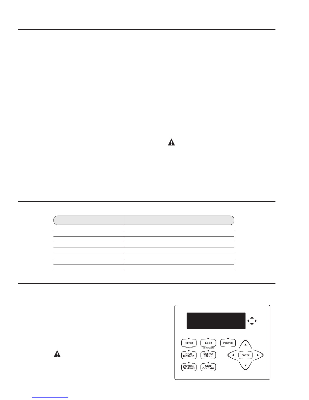
Controls
Display
Lock
Press and hold this button for 3 seconds to
lock or unlock the water heater touch button
controls. Green light is illuminated when the
controls are locked.
Filter
The filter is dirty and requires cleaning when
the Red light is illuminated. Filter is located on
top of the water heater. Press button to reset
filter alarm.
High Demand
Use this button when extra hot water is
needed. This feature increases the speed that
the water is heated using more electricity.
Green light is illuminated when feature is on.
Vacation Or Away
Use this button during times of no water
usage, such as vacation for an extended
period of time. Feature will reduce the energy
used during the absence. Green light is
illuminated when feature is on.
Stop Cold Air
Use this button to temporarily stop cold air
coming from the unit or to stop fan noise.
However, the unit will use more electricity,
so this mode should generally be used
only for short periods of time. Green light is
illuminated when feature is on.
Energy Menu
Change the water heater Operating Modes by
pressing this button. You can also change the
temperature display from ºF to ºC and
view FAQs.
Power
Use this button to activate or deactivate
all heating sources on this product.
NOTE: The user interface will still function
when the power button is off.
Arrow Pads
Use the up, down, left and right arrows to
navigate through menus or to change the
water temperature.
5
Page 6

Turning on the water heater.
The first time you press the power button and the
water heater is powered on, the screen will ask
for confirmation that the tank has been filled with
water. The tank must be full of water before the
heater is turned on to prevent damage.
The water heater warranty does not cover damage
or failure resulting from operation with an empty
or partially empty tank. (Refer to the Certificate
of Limited Warranty for complete terms and
conditions.)
If the tank has NOT been filled, vent and fill tank
with water before pressing the POWER button
again.
• Make sure the drain valve is completely closed.
• Open the shut-off valve in the cold water supply
line.
• Open each hot water faucet slowly to allow the
air to vent from the water heater and piping.
• A steady flow of water from the hot water
faucet(s) indicates a full water heater.
After the tank has been filled with water, press the
POWER button again.
Once the water heater has been powered on, the
main screen will be shown. The display will show
the current water temperature setting and the
current operating mode for the water heater.
If the display goes blank, press any key to reactivate
the display. To go back to the default (HOME) screen,
press the left arrow button until the default (HOME)
screen appears.
To comply with safety regulations, the controls are
factory preset to 120°F (49°C) and Hybrid Mode.
These are the recommended settings for the water
heater.
6
Page 7
About the water temperature setting. GEAppliances.com
The temperature of the water in the water heater can
be regulated by adjusting the temperature setting up
or down using arrow keys on the control panel.
Safety, energy conservation and hot water capacity
are factors to be considered when selecting the
water temperature setting of the water heater.
To comply with safety regulations, the water
temperature setpoint is factory set at 120°F (49°C).
This is the recommended starting point. However,
the GE Hybrid Water heater’s energy savings claims
are based on a 135°F (57°C) temperature setting
because, according to US Dept of Energy, the
average residential water heater in the US is set
at 135°F (57°C). Therefore, the water temperature
setpoint can be raised from the factory setting of
120°F to 135°F (49°C to 57°C) without sacrificing
the claimed energy savings. As always, if a lower
temperature setting than 135°F (57°C) is used,
slightly greater savings in energy and operating
costs may be achieved.
Finally, if more hot water capacity is desired,
increasing the temperature from 120°F to 135°F
(49°C to 57°C) will enable the same tank of hot
water to last about 25% longer because more cold
water is mixed in at the shower or faucet.
Adjust the water temperature setpoint as needed,
always being aware of scald risk.
Water temperatures above 125°F (52°C) can cause
severe burns or death from scalding. Be sure
to read and follow the warnings outlined in this
manual and on the label on the water heater. This
label is located on the water heater near the upper
element access panel.
Mixing valves for reducing point-of-use water
temperature by mixing hot and cold water in
branch water lines are available. Contact a licensed
plumber or the local plumbing authority for further
information.
The chart below may be used as a guide in
determining the proper water temperature for your
home.
DANGER: There is a hot water scald
potential if the water temperature is set too high.
Households with small children, disabled, or elderly
persons may require a 120°F (49°C) or lower
thermostat setting to prevent contact with HOT water.
Time/Temperature Relationship in Scalds
Temperature Time to Produce a Serious Burn
120°F (49°C) More than 5 minutes
125°F (52°C) 1-1/2 to 2 minutes
130°F (54°C) About 30 seconds
135°F (57°C) About 10 seconds
140°F (60°C) Less than 5 seconds
145°F (63°C) Less than 3 seconds
150°F (66°C) About 1-1/2 seconds
155°F (68°C) About 1 second
Table courtesy of Shriners Burn Institute
To Adjust the Temperature
Press the UP or DOWN arrow on the control panel
key pad. You will be asked to press the ENTER
key to acknowledge that increasing temperature
increases scald risk. Then the temperature can
be increased or decreased by pressing the UP
or DOWN arrows. After the desired temperature
setting has been achieved, you can press ENTER
to accept or simply walk away. (After 3 seconds
of no key presses, the control will accept the new
temperature setting.)
DANGER: There is a Hot Water SCALD
Potential if the water temperature is set too high.
120°F (49°C) is the recommended starting point for
water temperature setting, but it can be adjusted
to any temperature between 100°F and 140°F
(38°C and 60°C).
7
Page 8
Operational Modes.
This water heater defaults to the Hybrid operating
mode. The Hybrid mode is the recommended
setting for this water heater, but can be changed
if desired. Available modes are listed below and
can be found under the ENERGY MENU button.
eHeat™ Mode
eHeat™ is the most energy-ef cient mode for this
water heater. It takes heat from the surrounding
air to heat the water. The time it takes to heat
the water is longer in this mode, so it may NOT
be suf cient if you have a high-demand situation
such as a large household or company.
Standard Electric Mode
This mode uses only the upper and lower heating
resistance elements to heat the water. The time it
takes to heat the water is less in this mode, but it
is the LEAST energy-ef cient mode.
Hybrid ModeRECOMMENDED MODE
Hybrid mode combines the energy ef ciency of
eHeat™ with the recovery speed and power of the
Standard Electric mode, with normal water usage.
High Demand
This mode is only necessary if your household
has a higher-than-average water usage or the unit
is undersized for the household water demands.
In this mode, the unit will use the electric heating
elements only when the water demand is higher
than normal. When using the heating elements,
the water temperature will recover at a faster
rate but it will take more energy to heat it. Unlike
Standard Electric mode, it will use the heating
elements only when needed.
To access any of these modes:
Press the ENERGY MENU button and then
1
press ENTER.
Select “Operating Modes” on the menu list and
2
press ENTER.
Select the desired operating mode by using
3
the UP and DOWN arrow buttons and then
press ENTER again.
To cancel and return to the main energy menu:
Press the LEFT arrow button.
General navigation of energy menu:
For more information on each mode, while the
1
mode is highlighted, press the RIGHT arrow
button to read a description.
Use the UP and DOWN arrow buttons to scroll
2
through the description screens.
Use the LEFT arrow button to return to the
3
“Operating Modes” menu list.
8
Page 9

About the feature buttons on the user interface. GEAppliances.com
Vacation Or Away
This feature is used when you will be away from
the home for an extended period of time and hot
water is not needed. In this mode, the unit will drop
the water temperature down to 50ºF (10°C) and will
use the most ef cient heating mode to conserve
energy while the heater is sitting idle. The unit will
automatically resume heating one day before your
return, so that hot water will be available.
For example if you will be gone 14 days, press the
VACATION OR AWAY button, press the UP arrow
button until the display reads 14 days (the default
is 7 days) and press ENTER. The unit will drop
the water temperature down to 50ºF (10°C)
for 13 days. At the end of the 13th day, it will
automatically return to the previous operating
mode and heat the water to the original
temperature setting.
The green light will be illuminated when this
feature is on.
Stop Cold Air
The Hybrid and eHeat™ modes save energy by
using heat from the air to heat the water. The
warm air is pulled through the system by fans and
is then cooled. That cool air then moves out the
back of the heater.
You can temporarily stop the cold air and fan
noise coming from the unit by pressing the STOP
COLD AIR button.
To adjust the number of days this feature will be
on, simply use the UP and DOWN arrow buttons
and press ENTER (the default is 3 days). The unit
will automatically return to the previous operating
mode after the number of days selected has
passed.
This mode should only be used on a temporary
basis because you do NOT get the energy savings
while in this mode.
The green light will be illuminated when this
feature is on.
High Demand (on some models)
This mode is only necessary if your household has
a higher-than-average water usage or
the unit is undersized for the household water
demands.
In this mode, the unit will use the electric heating
elements only when the water demand is higher
than normal. When using the heating elements,
the water temperature will recover at a faster rate
but it will take more energy to heat it.
Unlike Standard Electric mode, it will use the
heating elements only when needed.
The green light will be illuminated when this
feature is on.
Control Lock
The control pad can be locked out to prevent
accidental key presses.
Simply press and hold the LOCK button for three
seconds. The display will show “controls are
locked” and the green light will be illuminated
when this feature has been activated. No other
key presses will be allowed when the controls are
locked.
To deactivate the lock, press and hold the LOCK
pad for three seconds. The green light will fade
and the screen will go to the default display.
9
Page 10

Using the Energy Menu.
10
The Energy Menu is also used to change the water heater
operating modes, to convert the temperature display from
ºF to ºC, or to view the FAQs. There is also a Diagnostic
Menu that is only accessible to a certi ed service
technician or plumber in the event service is needed.
Operating Modes
Use this option to change between eHeat™, Hybrid,
Standard Electric and High Demand modes (described
on page 8).
To access any of these modes, press the ENERGY
1
MENU button and then press ENTER.
Select Operating Modes on the menu list and
2
press ENTER.
Select the desired operating mode by using the UP or
3
DOWN arrow buttons and then pressing ENTER again.
To cancel and return to the main Energy Menu, press
4
the LEFT arrow button.
To get more information on each mode, while the
5
mode is highlighted, press the RIGHT arrow button
to read a description.
Use the UP or DOWN arrow buttons to scroll through
6
the description screens.
Use the LEFT arrow button to return to the Operating
7
Mode menu list.
ºF and ºC Conversion
The water temperature display will default to ºF. To show
the temperatures in ºC, press the ENERGY MENU button;
then press ENTER. These settings will be remembered
and returned following a power outage.
Press the DOWN arrow button to go to “Choose ºF
1
and ºC” and press ENTER.
Press ENTER to change from ºF to ºC. The main screen
2
will then be shown with the temperature in ºC.
To cancel and return to the main Energy Menu, press
3
the LEFT arrow button.
NOTE: To change back to ºF, repeat Steps 1 and 2.
Frequently Asked Questions
This menu item answers basic questions on cold air,
the lter, operating modes and noise. All of this information
is covered in this Use and Care manual. If this manual is
misplaced, you can refer to this section for answers.
To access the FAQs, press the ENERGY MENU button
1
and then press ENTER.
Press the DOWN arrow pad to go to “FAQs” and then
2
press ENTER.
There are four question categories:
Cold Air:
Q: Why is there cold air?
A: Hybrid, eHeat™ and High Demand modes save energy
by using heat from the air to heat the water and thereby
cooling the surrounding air. This gives sizable energy
savings.
Q: How to stop cold air?
A: Press the STOP COLD AIR button on the keypad. This
reduces the ef ciency of the heater. Unit will change
back to previous mode after number of days selected.
Filter:
Q: Why is there a lter?
A: In Hybrid and eHeat™ the unit moves air through the
system. The lter protects the unit from dirt. A clean air
lter improves ef ciency.
Q: How to clean the lter?
A: Leave power on and remove lter from top of unit. Filter
can be wiped clean or rinsed with warm water. A dirty
lter will reduce water heater ef ciency!
Modes:
Q: What is High Demand?
A: High Demand can be used when hot water usage is
higher than normal. The unit will be less ef cient but will
heat water faster in response to long water draws. For
all normal draws, the unit will still use ef cient eHeat™.
Q: What is Stop Cold Air?
A: This mode will stop cold air temporarily but reduces
the ef ciency of the heater. The unit will change back
to the previous mode after the number of days selected.
Q: What is Vacation Or Away?
A: If you are gone for an extended period, this mode
lowers the water temperature to reduce energy used.
Unit will switch to the previous mode one day before
you get back.
Q: What is eHeat™?
A: eHeat™ is the most-ef cient mode. It takes heat from
the air to heat water, thereby cooling the surrounding
air. Slower recovery but most-ef cient mode.
Q: What is Hybrid?
A: The Hybrid mode combines bene ts of eHeat™ with the
speed and power of Standard Electric. This provides great
performance with less energy. (Recommended mode.)
Q: What is Standard Electric?
A: Standard Electric mode uses only the resistance heaters
to heat the water. This gives faster hot water recovery
than Hybrid mode, but uses more energy.
Noise:
Q: Why is the unit noisy?
A: In the most energy-ef cient modes, eHeat™, Hybrid
and High Demand, the method used to heat the water
generates some noise. Some amount of fan noise is
normal.
Use the UP or DOWN arrow buttons to select the
3
category that pertains to your question and press
ENTER.
To cancel and return to the main Energy Menu, press
4
the LEFT arrow button.
Once the category is selected, use the UP or DOWN
5
arrow buttons to select the desired questions and
press ENTER.
Use the UP or DOWN arrow buttons to read through
6
the information screens.
When done, press the LEFT arrow button to return
7
to the FAQs menu.
Page 11
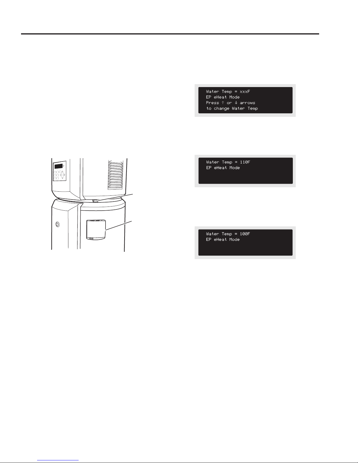
Smart Appliance. (on some models) GEAppliances.com
The Hybrid Electric heat pump water heater is compatible
with the GE Smart Appliance module (SAM) which can
be purchased separately. Contact your local utility or visit
www.GEAppliances.com/Smart-Appliance to see if your
area is using SAM technology.
The following demand response features are available
as part of a pilot test program with the local utility
company to help consumers reduce peak electricity
usage in the home.
INSTALLATION
The SAM module is equipped with magnets in the base
of the module that will enable it to be attached to the
painted metal exterior of the heat pump water heater.
Details on how to connect the cables to the module are
in the instructions that come with the module.
SAM connector
SAM module
When the SAM signal is Medium, the control will operate
in eHeat™ Mode and the water temperature will remain
at the current user setting. The screen will display the
following (where xxx is the current user temperature
setting):
When the SAM signal is High, the control will operate in
eHeat™ mode, with a water temperature setting of 110°F
(43°C), and the screen will display:
When the SAM signal is Critical, the control will operate in
eHeat™ mode, with a water temperature setting of 100°F
(38°C), and the screen will display:
Once the cable from the SAM module is plugged into the
water heater’s connection, follow the power-up directions
included with the SAM module. As soon as the SAM
module is operating, the heat pump water heater is ready
to receive the SAM signals.
QUICK GUIDE
If your local utility company is utilizing SAM technology,
the SAM module will receive the signals sent from your
utility company. One of four signals will be sent: “Low”
represents that the lowest energy cost rate is available,
“Medium” and “High” signals represent increasing energy
cost steps, and the Critical signal represents “peak rate”
energy. A heat pump water heater equipped with a SAM
module will automatically recognize what energy cost
rate is available and adjust its mode and temperature
setting to use less energy when rates are medium, high
and critical. When the heat pump water heater responds
to these signals, it will display the letters “EP” in the screen,
along with other information, indicating that energy
pricing periods are in effect.
When the signal is low or when no SAM module is
connected, the unit runs as normal. The following steps
show how the unit reacts to Medium, High and Critical
signal levels.
Notice: Appliance SAM connection carries voltage not
compatible to computers or accessories. Do NOT plug
laptops modems, routers, etc into the Appliance RJ45
SAM connector. Use only with designated GE Appliance
Accessories. Connection to computers and accessories
may result in product damage.
11
Page 12

Care and cleaning of the water heater.
Routine Preventive Maintenance
DANGER: Before manually operating
the relief valve, make certain no one will be
exposed to the danger of coming in contact with
the hot water released by the valve. The water
may be hot enough to create a scald hazard. The
water should be released into a suitable drain to
prevent injury or property damage.
NOTE: If the temperature and pressure-relief
valve on the hot water heater discharges
periodically, this may be due to thermal expansion
in a closed water system. Contact the water
supplier or your plumbing contractor on how to
correct this. Do not plug the relief valve outlet.
Properly maintained, your water heater will provide
years of dependable trouble-free service.
It is suggested that a routine preventive maintenance
program be established and followed by the user.
Temperature and Pressure-Relief Valve:
At least once a year, lift and release the lever handle
on the temperature and pressure-relief valve, located
on the back-right side of the water heater, to make
certain the valve operates freely. Allow several
gallons to flush through the discharge line to an
open drain.
Periodic Inspection:
It is further recommended that a periodic inspection
of the operating controls, heating elements and
wiring should be made by service personnel
qualified in electric appliance repair.
Most electrical appliances, even when new, make
some sound when in operation. If the hissing or
singing sound level increases excessively, the electric
heating element may require cleaning. Contact a
qualified installer or plumber for inspection.
Flushing Tank:
A water heater’s tank can act as a settling basin
for solids suspended in the water. It is therefore not
uncommon for hard water deposits to accumulate
in the bottom of the tank. To clean the tank of these
deposits, open the drain valve located under the
large decorative cover near the bottom of the unit
and drain a few quarts of water from the water
heater every month. This should be done with the
cold water supply open such that water removed
through drain valve is replaced, and water supply
flow helps to remove sediment.
Draining the Water Heater
CAUTION: Shut off power to the
water heater before draining water.
DANGER: Before manually operating
the relief valve, make certain no one will be
exposed to the hot water released by the valve. The
water drained from the tank may be hot enough to
present a scald hazard and should be directed
to a suitable drain to prevent injury or damage.
Vacation and Extended Shutdown
If the water heater is to remain idle for an extended
period of time, the power and water to the
appliance should be turned off to conserve energy
and prevent a buildup of dangerous hydrogen
gas.
Attach a garden hose to the drain valve located
at the bottom of the unit and direct that hose
to a drain. The decorative front cover must be
removed to access the valve.
In order to drain the water heater completely, turn
off the cold water supply. Open a hot water faucet
or lift the handle on the relief valve to admit air to
the tank.
Open the drain valve.
Use a flat
screwdriver
to turn
valve.
After a long shutdown period, the water heater’s
operation and controls should be checked by
qualified service personnel. Make certain the
water heater is completely filled again before
placing it in operation.
The water heater and piping should be drained if
12
they might be subjected to freezing temperatures.
NOTE: Refer to the Hydrogen Gas Caution
in the Operating Instructions.
Page 13
GEAppliances.com
Cleaning the Filter
In the Hybrid, eHeat™ and High Demand modes,
the heater moves air through the system and out
the back of the unit. The filter is in place to protect
the evaporator from dirt and dust.
A clean air filter is important to get the highest
efficiency. Occasionally this filter will need to be
cleaned (minimum is once a year). When the filter
requires cleaning, the Red light above the Filter
button will be illuminated and an audible beep
will sound. The screen will display instructions that
the filter needs to be cleaned. When this screen is
displayed, you can press the RIGHT arrow button for
instructions on how to clean the filter.
NOTE: If the filter gets too dirty, the unit will
automatically switch to Standard Electric mode
and energy savings will be lost.
Leave the power on and remove the filter from
the top of the unit. It is located in the top of the unit
behind the hot and cold inlet pipes. Grasp the plastic
handle and slide the filter straight up until it clears
the cover. Once it has been removed, the filter can
be wiped clean with a damp rag or rinsed with
warm water.
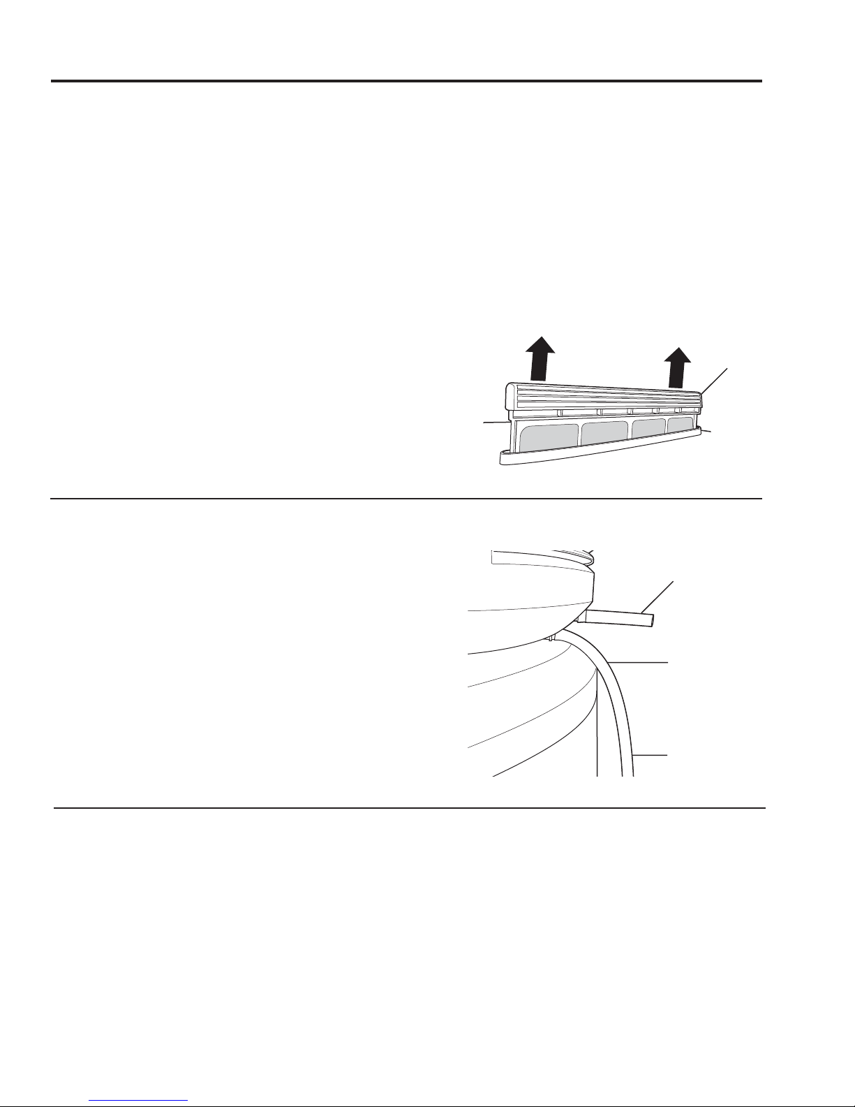
Clearing the Condensation Drain Tubes
Once the filter has been cleaned, it can be replaced
by aligning it into the slot in the top of the unit and
sliding it down into place. When the handle is flush
with the top of the cover, it is seated.
When the clean filter has been reinstalled, press
the FILTER button and then press ENTER.
IMPORTANT: Filter must be cleaned when the alarm
is displayed. A dirty filter will make the system work
harder and result in a reduction of efficiency and
possible damage to the system. In order to get the
best energy efficiency available, make sure your filter
is clean.
Filter
Rear of unit
There are two drain hoses that are attached to
the back of the heater. If both of these get clogged,
water will spill down the outside of the unit.
The primary drain is intended to carry all condensate
away. If it is clogged or if the hose is kinked, the
condensate will exit the secondary drain tube
and onto the floor. This is intended as a notification
to the user that the primary drain is clogged. Remove
the drain hose, clear any debris and reattach.
Periodically inspect the drain lines and clear any
debris that may have collected in the lines.
See Installation Instructions for more information.
Anode Rod
The anode rod should be removed from the water
heater’s tank and inspected annually, and replaced
when more than 6” (15.2 cm) of core wire is exposed
at either end of the rod.
Due to shock hazard and to prevent accidental water
leaks, this inspection should be done by a qualified
servicer or plumber, and requires that the cold water
supply is turned off before removing the anode rod.
3” (7.6 cm) tube (overflow)
Main drain tube
Direct the main drain
tube into a drain
NOTICE: Do not remove the anode rod from the
water heater’s tank except for inspection and/
or replacement, as operation with the anode rod
removed will shorten the life of the glass-lined tank
and will exclude warranty coverage.
13
Page 14

Installation
Models GEH50DNSRSA and GEH50DXSRGA
Instructions
Water Heater
The location chosen for the water heater must take into
consideration the following:
LOCAL INSTALLATION REGULATIONS
This water heater must be installed in accordance
with these instructions, local codes, utility codes,
utility company requirements or, in the absence of
local codes, the latest edition of the National Electrical
Code. It is available from some local libraries or can be
purchased from the National Fire Prevention Association,
Batterymarch park, Quincy, MA 02169 as booklet ANSI/
NFPA 70.
POWER REQUIREMENTS
Check the markings on the rating plate of the water
heater to be certain the power supply corresponds to
the water heater requirements.
LOCATION
Locate the water heater in a clean dry area as near as
practical to the area of greatest heated water demand.
Long uninsulated hot water lines can waste energy and
water.
NOTE: Because this unit draws in air from the room to
heat the water, the room must be at least 10’ x 10’ x 7’
(700 cubic feet)/3m x 3m x 2.1m (19.8 m3) or larger. If
the room is smaller, there must be a louvered door. If
a louvered door is required, the total louver flow area
should be 240 sq. inches (0.15 m
good air-exchange with the adjacent room. The ideal
louver configuration is full-door type, but two louvered
areas, one positioned in upper and lower section of door
is acceptable.
Place the water heater in such a manner that the air
filter, cover and front panels can be removed to permit
inspection and servicing, such as removal of elements
or cleaning of the filter.
The water heater and water lines should be protected
from freezing temperatures and high-corrosive
atmospheres. Do not install the water heater in outdoor,
unprotected areas.
2
) or greater to ensure
CAUTION: The water heater should not
be located in an area where leakage of the tank or
connections will result in damage to the area adjacent
to it or to lower floors of the structure. Where such areas
cannot be avoided, it is recommended that a suitable
catch pan, adequately drained, be installed under the
water heater.
LOCATION (CONT.)
WATER HEATER SIZING INFORMATION - READ
BEFORE INSTALLING:
For existing home replacements:
• Replacing an existing tank water heater?
current water heater has provided adequate hot water,
and no other plumbing changes and/or renovations that
would require additional hot water demand are in process or
planned, then:
• The GeoSpring Hybrid water heater can replace an
equivalent size or smaller standard electric water heater.
(e.g. if you have a 40 or 50 gallon (151.4 or 189.3 L)
standard electric water heater today, a 50 gallon (189.3 L)
GeoSpring will be a good replacement).
• If switching from gas to electric, the GeoSpring Hybrid water
heater may replace the next size smaller gas tank water
heater. (i.e. 50 gallon/189.3 L GeoSpring can replace a
40 gallon/151.4 L or smaller gas water heater).
For new construction installation:
Residental Water Heater Sizing Guide
Family
Size
3 to 4 High 80 (302.8 L) 50-75 (189.3-283.9 L)
2 to 3 High 50 (189.3 L) 40-50 (151.4-189.3 L)
1 to 2 High 40-50 (151.4-189.3 L) 40-50 (151.4-189.3 L)
*Assumptions for Avg or Low Demand household:
- Use of standard or low flow shower heads (2.5 gpm/11.4 L per minute or less)
- No showers with multiple shower heads and/or body jets.
- Standard bathtub (no oversized/jetted tubs)
Demand * Gallon Capacity Recommended
Electric
or GeoSpring Gas
5+ High 100 (378.5 L) 75 (283.9 L)
Avg or Low 80 (302.8 L) 50 (189.3 L)
Avg or Low 50 (189.3 L) 40 (151.4 L)
Avg or Low 40 (151.4 L) 40 (181.8 L)
Avg or Low 30 (113.6 L) 30 (113.6 L)
Water Heater Temperature Setpoint:
The water heater temperature setting strongly impacts the
amount of hot water available for showers and baths.
• The average setting of water heaters in the USA is about
135°F (57°C), so energy consumption/savings and efficiency
testing of water heaters, including the GeoSpring, is
performed at a 135°F (57°C) setting.
• Safety regulations require a factory setting of 120°F to 125°F
(49°C to 52°C) max for all new water heaters. Therefore, if
your water heater is currently set at 130°F (54°C) or above
and your new water heater is installed with a factory set
setpoint of 120°F (49°C), the new water heater may seem to
provide lower capacity than your existing water heater.
• The user can adjust the temperature setting to meet their
needs. Always read and understand the safety instructions
contained in the users manual before adjusting the
temperature setpoint.
If your
14
Page 15

Installation Instructions
LOCATION (CONT.)
Route to open drain. Line
should be at least 3/4”
(1.9 cm) ID and pitched
for proper drainage.
B
A— Diameter of water heater
plus 2” (5.1 cm) min.
A
NOTE: Auxiliary catch pan MUST conform to local codes.
Catch Pan Kits are available from the store where the water
heater was purchased, a builder store or any water heater
distributor.
Required clearances:
There must be a 5-1/2” (14 cm) minimum (7”/17.8 cm
recommended) clearance between any object and the Front
and Rear covers in the event service is needed. A minimum of
3” (7.6 cm) clearance with the sides of the water heater is also
recommended for service access.
5-1/2”
(14 cm)
A 14” (35.6 cm) minimum clearance is required to remove the
filter for cleaning. The hot and cold water plumbing
and electrical connections must not interfere with
the removal of the filter.
B— Maximum 2” (5.1 cm)
5-1/2”
(14 cm)
14” (35.6 cm)
THERMAL EXPANSION
Determine if a check valve exists in the inlet water
line. It may have been installed in the cold water line as
a separate backflow preventer, or it may be part of a
pressure-reducing valve, water meter or water softener.
A check valve located in the cold water inlet line can
cause what is referred to as a “closed water system.”
A cold water inlet line with no check valve or backflow
prevention device is referred to as an “open” water
system.
As water is heated, it expands in volume and creates
an increase in the pressure within the water system.
This action is referred to as “thermal expansion.” In an
“open” water system, expanding water which exceeds the
capacity of the water heater flows back into the city main
where the pressure is easily dissipated.
A “closed water system,” however, prevents the
expanding water from flowing back into the main
supply line, and the result of “thermal expansion” can
create a rapid and dangerous pressure increase in the
water heater and system piping. This rapid pressure
increase can quickly reach the safety setting of the relief
valve, causing it to operate during each heating cycle.
Thermal expansion, and the resulting rapid and repeated
expansion and contraction of components in the water
heater and piping system, can cause premature failure of
the relief valve, and possibly the heater itself. Replacing
the relief valve will not correct the problem!
The suggested method of controlling thermal expansion
is to install an expansion tank in the cold water line
between the water heater and the check valve (refer to
the illustration on right). The expansion tank is designed
with an air cushion built in that compresses as the system
pressure increases, thereby relieving the over-pressure
condition and eliminating the repeated operation of
the relief valve. Other methods of controlling thermal
expansion are also available. Contact your installing
contractor, water supplier or plumbing inspector for
additional information regarding this subject.
Condensation drain
The unit has a condensate drain; therefore a drain must be
available in close proximity to the unit. The drain must be no
higher than 36” (91.4 cm) above the floor (laundry drain is
acceptable).
If no drain is available, then a common condensate pump with
a capacity no less than 1 gallon (3.8 L)/day must be purchased
from a local builder and supply store and installed.
15
Page 16

Installation Instructions
WATER SUPPLY CONNECTIONS
Refer to the illustration below for suggested typical installation.
The installation of unions or flexible copper connectors is
recommended on the hot and cold water connections so that
the water heater may be easily disconnected for servicing if
necessary. The HOT and COLD water connections are clearly
marked and are 3/4” NPT on all models.
NOTE: Install a shut-off valve in the cold water line near the
water heater. This will enable easier service or maintenance
of the unit later.
IMPORTANT:Do not apply heat to the HOT or COLD water
connections. If sweat connections are used, sweat tubing
to adapter before fitting the adapter to the cold water
connections on heater. Any heat applied to the hot or cold
water connection will permanently damage the internal
plastic lining in these ports.
TYPICAL INSTALLATION
To electrical
distribution panel
Union
Hot water
outlet to xtures
Temperature and
pressure-relief valve
(shown in different
location for clarity)
Relief valve
discharge line to
suitable open drain
6” ( 15.2 cm)
air gap
Union
To cold
water
supply
Shut-off valve
Thermal expansion
tank (if required)
Electrical junction
box (use only
copper conductors)
Jacket access panel
Jacket access panel
Auxiliary catch
pan 2” (5.1 cm)
maximum
Drain valve
CONDENSATION DRAIN TUBES
This unit has a condensation tray. The water collected in the
tray drains out of the tube coming off the back of the unit.
Two flexible hoses are included with this unit. It is important
that both of these hoses are attached to the two drain ports
coming off the back of the unit. Attach one end of the longer
6’ (1.8 m) hose to the lower drain port on the back of the unit,
underneath the rear cover. Direct
the other end to a drain in the floor
or no higher than 3’ (0.9 m) above
the floor. If such drain is unavailable,
a condensate drain pump (not
provided) must be purchased and
installed. Attach the shorter 3”
(7.6 cm)hose to the top drain port.
3” (7.6 cm)
hose
6’ (1.8 m)
hose
A new combination temperature and pressure-relief
valve, complying with the Standard for Relief Valves and
Automatic Gas Shut-Off Devices for Hot Water Supply
Systems, ANSI Z21.22, is supplied and must remain installed
in the opening provided and marked for the purpose on
the water heater. No valve of any type should be installed
between the relief valve and the tank. Local codes shall
govern the installation of relief valves.
RELIEF VALVE
WARNING: The pressure rating of the relief
valve must not exceed 150 PSI (1.03 kPa), the maximum
working pressure of the water heater as marked on the
rating plate.
The BTUH rating of the relief valve must not be less than the
input rating of the water heater as indicated on the rating
label located on the front of the heater (1 watt=3.412 BTUH).
Connect the outlet of the relief valve to a suitable open drain
so that the discharge water cannot contact live electrical
parts or persons and to eliminate potential water damage.
Piping used should be of a type approved for hot water
distribution. The discharge line must be no smaller than the
outlet of the valve and must pitch downward from the valve
to allow complete drainage (by gravity) of the relief valve
and discharge line. The end of the discharge line should
not be threaded or concealed and should be protected
from freezing. No valve of any type, restriction or reducer
coupling should be installed in the discharge line.
CAUTION:
To reduce the risk of excessive pressures and
temperatures in this water heater, install temperature
and pressure protective equipment required by local
codes and no less than a combination temperature and
pressure relief valve certified by a nationally recognized
testing laboratory that maintains periodic inspection of
production of listed equipment or materials, as meeting
the requirements for Relief Valves and Automatic Gas
Shutoff Devices for Hot Water Supply Systems, ANSI
Z21.22. This valve must be marked with a maximum set
pressure not to exceed the marked maximum working
pressure of the water heater. Install the valve into an
opening provided and marked for this purpose in the
water heater, and orient it or provide tubing so that
any discharge from the valve exits only within 6 inches
above, or at any distance below, the structural floor, and
does not contact any live electrical part. The discharge
opening must not be blocked or reduced in size under
any circumstances.
16
Page 17

Installation Instructions
TO FILL THE WATER HEATER
WARNING: The tank must be full of water
before heater is turned on. The water heater warranty
does not cover damage or failure resulting from
operation with an empty or partially empty tank.
Make certain the drain valve is completely closed.
Open the shut-off valve in the cold water supply line.
Open each hot water faucet slowly to allow the air to
vent from the water heater and piping.
A steady flow of water from the hot water faucet(s)
indicates a full water heater.
NOTICE:
Do not mis-wire electrical connections. 240V AC must be
applied across L1 and L2 wires as shown in ‘Water heater
junction box’ illustration. Failure to do so will VOID the
warranty, and can result in 120V applied to water heater,
which may damage the compressor or other electrical
components.
If 4-conductor wire is supplied to the water heater, cap the
neutral, and connect the remaining wires as illustrated.
NOTE REGARDING UTILITY POWER-MANAGEMENT DEVICES
(Sometimes called Peak Load Reduction Switches):
Some power-management switching devices or even some
basic timer switches exist that REDUCE voltage from 240V
to 120V during high-electricity-demand periods. These
devices must be removed from the circuit providing power
to the water heater because of the potential unit damage
noted above.
However, switching devices which cut power from 240V to
0V on a periodic basis are acceptable.
ELECTRICAL CONNECTIONS
A separate branch circuit with copper conductors, overcurrent
protective device and suitable disconnecting means must be
provided by a qualified electrician.
All wiring must conform to local codes or latest edition of
National Electrical Code ANSI/NFPA 70.
The water heater is completely wired to the junction box at the
top of the water heater. An opening for 1/2” or 3/4” electrical
fitting is provided for field wiring connections.
The voltage requirements and wattage load for the water
heater are specified on the rating label on the front of the
water heater.
The branch circuit wiring should include either:
1. Metallic conduit or metallic sheathed cable approved
for use as a grounding conductor and installed with
fittings approved for the purpose.
2. Nonmetallic sheathed cable, metallic conduit or
metallic sheathed cable not approved for use as a
ground conductor shall include a separate conductor
for grounding. It should be attached to the ground
terminals of the water heater and the electrical
distribution box.
Junction box cover
Ground screw
L2
240V
L1
Water heater junction box
WARNING: Proper ground connection is
essential. The presence of water in the piping and water
heater does not provide sufficient conduction for a
ground. Nonmetallic piping, dielectric unions, flexible
connectors, etc., can cause the water heater to be
electrically isolated.
17
Page 18

Installation Instructions
The manufacturer’s warranty does not cover any
damage or defect caused by installation, attachment
or use of any type of energy-saving or other
unapproved devices (other than those authorized by the
manufacturer) into, onto or in conjunction with the water
heater. The use of unauthorized energy-saving devices
may shorten the life of the water heater and may
endanger life and property.
The manufacturer disclaims any responsibility for
such loss or injury resulting from the use of such
unauthorized devices.
If local codes require external application of insulation
blanket kits, the manufacturer’s instructions included
with the kit must be carefully followed.
Application of any external insulation, blankets or
water pipe insulation to this water heater will require
careful attention to the following:
• Do not cover the temperature and pressure-relief
valve.
• Do not cover access panels to the heating elements.
• Do not cover the electrical junction box of the
water heater.
• Do not cover the operating or warning labels attached
to the water heater or attempt to relocate them on
the exterior of the insulation blanket.
• Do not block the air inlet outlets below and in the top
covers.
NOTE: This guide recommends minimum branch
circuit sizing based on the National Electric Code.
Refer to wiring diagrams in this manual for eld wiring
connections.
BRANCH CIRCUIT SIZING GUIDE
Total Water Recommended Over-Current Protection
Heater Wattage (fuse or circuit breaker amperage rating)
208V 240V 277V 480V
3,000 20 20 15 15
4,000 25 25 20 15
4,500 30 25 25 15
5,000 30 30 25 15
5,500 35 30 25 15
6,000 40 35 30 20
8,000 50 45 40 25
9,000 – 50 45 25
10,000 – – 50 30
11,000 – – 50 30
12,000 – – – 35
Total Water Copper Wire Size AWG Based
Heater Wattage on N.E.C. Table 310-16 (167°F/75°C.)
208V 240V 277V 480V
3,000 12 12 14 14
4,000 10 10 12 14
4,500 10 10 10 14
5,000 10 10 10 14
5,500 8 10 10 14
6,000 8 8 10 12
8,000 8 8 8 10
9,000 – 8 8 10
10,000 – – 8 10
11,000 – – 8 10
12,000 – – – 8
Typical vertical
piping arrangement
Typical horizontal piping
arrangement
18
Page 19

Installation Instructions
INSTALLATION CHECKLIST
1. Tank location:
– Is room size less than 10’ x 10’ x 7’ (700 cu. ft.)/ 3m x 3m x 2.1m (19.8 m3)? If yes, louvered door
(with 240 square inches (0.15 m2) of air-flow area) or similar ventilation is needed.
– Back of unit away from wall by 7 inches (17.8 cm), and sides have at least 3 inches (7.6 cm) clearance.
– Front of unit is free and clear.
– Is the water heater level? If no, add shims under the base of the unit.
2. Plumbing connections:
– Does not prevent air filter removal.
– No leaks after filling the tank with water, either when water is flowing or not.
3. Condensate lines are in place:
1) Short tube on upper drain nozzle.
2) Longer tube on lower drain nozzle and directed into a floor drain or a condensate pump.
4. Temperature and pressure-relief valve is working and drain line completed per local code.
5. Electrical connection does not prevent air filter removal.
6. Verify control panel displays 120°F (49°C) Hybrid mode. Assist user in how to adjust temperature (see “About Setting
the Water Temperature” section on page 5).
7. Front cover is in place.
WHAT TO EXPECT FOR “NORMAL STARTUP”
After the unit has been installed, with all electrical and water connections secure and checked, then the unit should be
filled with water (vent tank by opening a hot water faucet somewhere in home to allow tank to fully fill with water). Once
tank is full and power is energized, the user must press the POWER button on the user interface. The unit will then remind
the user to ensure tank has been filled, and to acknowledge by pressing POWER again.
Elapsed Time HEWH Actions Comments
0 to 1.5 minutes Unit is silent This 3-minute off -time prevents compressor
1.5 to 3 minutes Fans turn on
3 to 8 minutes Compressor turns on and runs for
5 minutes
8 to 30 minutes Compressor turns off, and Upper
Element turns on for about
20 minutes
30 minutes and
beyond
Upper element turns off and compressor turns back on
damage.
This 5-minute period is used to ensure the tank is
full of water (Dry-fire prevention algorithm).
To quickly provide initial amount of hot water for
user (about 25 gallons/94.6 L).
Uses efficient heat pump for majority of heating
NOTE: The heat pump operating range is 45°F to 120°F (7°C to 49°C). If the ambient temperature is outside of this range,
the heat pump will turn off and the backup electric elements will be used until the ambient temperature returns to within
the operating range.
19
Page 20

Before you call for service…
Troubleshooting Tips
Save time and money! Review the chart below first and you
may not need to call for service.
Problem Possible Causes What To Do
Water heater is noisy Fans are used to move air • Some amount of fan noise is normal (similar to the blower
through the system. The fan on a central heating and cooling system). If you hear an
noise volume will vary as the abnormal noise like a knocking or the noise level seems
water is heated. unusually loud, then contact service.
• If noise level has been increasing over the last weeks or
months, the filter may be getting dirty, thus making the
fans work harder. Check to see if filter needs to be cleaned.
(See page 13 for instructions.)
Water heater is Room is not vented • If the room is smaller than 10’ x 10’ x 7’ (3m x 3m x 2.1m),
making the room properly or is too small. then it must have a louvered door or other means to allow
too cold air exchange with surrounding rooms.
Water dripping down Condensate drain hoses are • Two drain hoses are included with your water heater.
the outside of the not connected. Connect the longer 6’ (1.8 m) hose to the lower condensate
heater drain port. Connect the short 3” (7.6 cm) hose to the upper
condensate drain port.
Condensate drain hoses are
kinked or clogged. line. You can use a small wire like a hanger or a small
screwdriver to clear out any debris in the drain port on
the unit.
Hot/Cold water connections • Tighten the inlet and outlet pipe connections.
are not tightened.
Not enough or no hot Water usage may have • Wait for the water heater to recover after an abnormal
water exceeded the capacity demand.
of the water heater.
A fuse is blown or a circuit • Replace fuse or reset circuit breaker.
breaker tripped.
Electric supply may be off. • Make sure electric supply to water heater and disconnect
switch, if used, are in the ON position.
Water temperature may • See the Water temperature setting section.
be set too low.
Leaking or open hot water
faucets.
Electric service to your home
may be interrupted.
Improper wiring.
Manual reset limit (TCO). • See the Water temperature setting section.
Cold water inlet temperature • This is normal. The colder inlet water takes longer to heat.
may be colder during the
winter months.
Water is too hot Water temperature is set • See the Water temperature setting section.
too high.
• Remove each drain hose and clear any debris from the
• Make sure all faucets are closed.
• Contact the local electric utility.
• See the Installation Instructions section.
CAUTION: For your safety, DO NOT attempt repair of electrical wiring, controls,
heating elements or other safety devices. Refer repairs to qualified service personnel.
Electronic control has failed. • Call for service.
Rumbling noise Water conditions in your • Remove and clean the heating elements.
home caused a buildup of
scale or mineral deposits
on the heating elements.
20
Page 21

Before you call for service… GEAppliances.com
Problem Possible Causes What To Do
Relief valve producing Pressure buildup caused • This is an unacceptable condition and must be corrected.
popping noise by thermal expansion Contact the water supplier or plumbing contractor on how
or draining to a closed system. to correct this. Do not plug the relief valve outlet.
The heater is beeping The water heater has not
and the screen says been filled with water before the alarm and then press POWER when the tank has been
“Attention! Tank not powering up. Powering up the filled.
filled!” heater without water will
damage the electric heaters.
The water heater warranty
does not cover damage or
failure resulting from operation
with an empty or partially
empty tank.
The filter light is on. The filter requires cleaning. • Follow the instructions on how to remove and clean the
A clean filter is necessary for filter on page 13.
effective operation.
The heater is beeping There is an issue with the • The unit will automatically switch to another available
and the screen says heat pump system. mode to ensure you continue to have hot water. Contact
“Heat Pump Failure” service immediately and give them the codes listed on the
display screen.
The heater is beeping There is an issue with the • The unit will automatically switch to another available
and the screen says water heater system. mode to ensure you continue to have hot water. Contact
“Water Heater Failure”
display screen.
• Fill the tank completely with water. Press ENTER to stop
service immediately and give them the codes listed on the
The heater is beeping There is an issue with the • The heater will need to turn off. Contact service immediately.
and the screen says water heater that requires
“System Failure” immediate attention.
The water heater is Unit is not receiving 240VAC • Turn off power to water heater (generally at the breaker
beeping and the screen as intended panel). Then read “Electrical Connections” section of
says, “Wiring to unit Installation Instructions, see page 17. Then, contact the
incorrect. Must be 240V installer to verify electrical input to the water heater.
not 120V” or “Heat Pump
Fault”
Hot Water has a rotten Certain water supplies with • The odor can be reduced or eliminated in most water
egg or sulfur smell high sulfate content will react heaters by replacing the anode rod with less-active
with the anode rod that is material rod. In some cases, an added step of
present in all water heaters chlorinating the water heater and all hot water lines may
for corrosion protection of be necessary, contact your local water professional or
the tank. plumber for options and instructions. Call GE at
1.888.4GE.HEWH (1.888.443.4394) to learn how to purchase
this replacement anode rod. A qualified servicer or
plumber should do this replacement. Use of a non-GE
approved anode rod, or operating the water heater
without a GE approved anode rod will VOID the warranty.
Unit is not making If unit is using resistance
noise elements, it will not make
noise.
• Check mode of unit.
For Service, please call 1.888.4GE.HEWH (1.888.443.4394)
In Canada, please call 1.855.742.6112
21
Page 22

GE Hybrid Water Heater Warranty (In the United States).
All warranty service provided by our Authorized Servicer Network.
To schedule service, call 888.4GE.HEWH (888.443.4394). Please
have serial number and model number availa ble when calling for
service.
Staple your receipt here.
Proof of the original purchase
date is needed to obtain
service under the warranty.
For The Period Of: We Will Replace:
One Year Any part of the Hybrid Water Heater which fails due to a defect in materials or workmanship.
From the date of the During this limited one-year warranty, GE will also provide, free of charge, all labor and related
original purchase service to replace the defective part.
Second through Any part of the Hybrid Water Heater which fails due to a defect in materials or workmanship.
Tenth Year During this limited ten-year parts warranty, labor and related service to replace the defective part
From the date of the are not included.
original purchase
What Is Not Covered (In the United States):
Service trips to your home to teach you how to use
the product.
Improper installation, delivery or maintenance.
Failure of the product if it is abused, misused, altered,
used commercially or used for other than the intended
purpose.
Use of this product where water is microbiologically
unsafe or of unknown quality, without adequate
disinfection before or after the system.
Replacement of house fuses or resetting of circuit
breakers.
Damage to the product caused by accident, lightning,
fire, flood or acts of God.
Incidental or consequential damage caused by possible
defects with this appliance, its installation or repair.
Product not accessible to provide required service.
If product removed from original installation location.
Damages, malfunctions or failure caused by the use of
repair service not approved by GE.
Damages, malfunctions or failure caused by the use of
unapproved parts or components.
Damages, malfunctions or failure caused by operating
the heat pump water heater with the anode rod
removed.
Damages, malfunctions or failure resulting from
operating the heat pump with an empty or partially
empty tank.
Damages, malfunctions or failure caused by subjecting
the tank to pressure greater than those shown on the
rating label.
Damages, malfunctions or failure caused by operating
the heat pump water heater with electrical voltage
exceeding those shown on the rating label.
Water heater failure due to the water heater being
operated in a corrosive atmosphere.
EXCLUSION OF IMPLIED WARRANTIESYour sole and exclusive remedy is product repair as provided in
this Limited Warranty. Any implied warranties, including the implied warranties of merchantability or
fitness for a particular purpose, are limited to one year or the shortest period allowed by law.
This warranty is extended to the original purchaser and any succeeding owner for products purchased for home
use within the USA. If the product is located in an area where service by a GE Authorized Servicer is not available,
you may be responsible for a trip charge or you may be required to bring the product to an Authorized GE Service
location for service. In Alaska, the warranty excludes the cost of shipping or service calls to your home.
Some states do not allow the exclusion or limitation of incidental or consequential damages. This warranty
gives you specific legal rights, and you may also have other rights which vary from state to state. To know
what your legal rights are, consult your local or state consumer affairs office or your state’s Attorney
General.
Warrantor: General Electric Company. Louisville, KY 40225
22
Page 23

GE Hybrid Water Heater Warranty (In Canada).
All warranty service provided by our Factory Service Centres or an
authorized technician. For service, call 1.800.561.3344.
Please have serial number and model number available when
calling for service.
Staple your receipt here.
Proof of the original purchase
date is needed to obtain
service under the warranty.
For The Period Of: We Will Replace:
One Year Any part of the Hybrid Water Heater which fails due to a defect in materials or workmanship.
From the date of the During this limited one-year warranty, MABE will also provide, free of charge, all labor and related
original purchase service to replace the defective part.
Second through Any part of the Hybrid Water Heater which fails due to a defect in materials or workmanship.
Tenth Year During this limited ten-year parts warranty, labor and related service to replace the defective part
From the date of the are not included.
original purchase
What Is Not Covered
Service trips to your home to teach you how to use
the product.
Improper installation, delivery or maintenance.
Failure of the product if it is abused, misused, altered,
used commercially or used for other than the intended
purpose.
Use of this product where water is microbiologically
unsafe or of unknown quality, without adequate
disinfection before or after the system.
Replacement of house fuses or resetting of circuit
breakers.
Damage to the product caused by accident, lightning,
fire, flood or acts of God.
Incidental or consequential damage caused by possible
defects with this appliance, its installation or repair.
Product not accessible to provide required service.
If product removed from original installation location.
(In Canada):
Damages, malfunctions or failure caused by the use of
repair service not approved by MABE.
Damages, malfunctions or failure caused by the use of
unapproved parts or components.
Damages, malfunctions or failure caused by operating
the heat pump water heater with the anode rod
removed.
Damages, malfunctions or failure resulting from
operating the heat pump with an empty or partially
empty tank.
Damages, malfunctions or failure caused by subjecting
the tank to pressure greater than those shown on the
rating label.
Damages, malfunctions or failure caused by operating
the heat pump water heater with electrical voltage
exceeding those shown on the rating label.
Water heater failure due to the water heater being
operated in a corrosive atmosphere.
EXCLUSION OF IMPLIED WARRANTIESYour sole and exclusive remedy is product repair as provided in
this Limited Warranty. Any implied warranties, including the implied warranties of merchantability or
fitness for a particular purpose, are limited to one year or the shortest period allowed by law.
This warranty is extended to the original purchaser and any succeeding owner for products purchased for home
use within Canada. If the product is located in an area where service by a MABE Authorized Servicer is not available,
you may be responsible for a trip charge or you may be required to bring the product to an Authorized MABE Service
location for service.
Some provinces do not allow the exclusion or limitation of incidental or consequential damages. This
warranty gives you specific legal rights, and you may also have other rights which vary from province to
province.
Warrantor: MABE Canada Inc.. Burlington, Ontario
23
Page 24

Consumer Support
GE Appliances Website In the U.S.: GEAppliances.com
Have a question or need assistance with your appliance? Try the GE Appliances Website 24 hours a day, any day
of the year! For greater convenience and faster service, you can now download Owner’s Manuals, order parts or
even schedule service on-line. In Canada: www.GEAppliances.ca
Schedule Service In the U.S.: GEAppliances.com
Expert GE repair service is only one step away from your door. Get on-line and schedule your service
at your convenience any day of the year! Or call 800.GE.CARES (800.432.2737) during normal business hours.
In Canada, call 1.855.742.6112
Real Life Design Studio In the U.S.: GEAppliances.com
GE supports the Universal Design conceptproducts, services and environments that can be used by people of
all ages, sizes and capabilities. We recognize the need to design for a wide range of physical and mental abilities
and impairments. For details of GE’s Universal Design applications, including kitchen design ideas for people with
disabilities, check out our Website today. For the hearing impaired, please call 800.TDD.GEAC (800.833.4322).
In Canada, contact: Manager, Consumer Relations, Mabe Canada Inc.
Suite 310, 1 Factory Lane
Moncton, N.B. E1C 9M3
Extended Warranties In the U.S.: GEAppliances.com
Purchase a GE extended warranty and learn about special discounts that are available while your warranty is still
in effect. You can purchase it on-line anytime, or call 800.626.2224 during normal business hours. GE Consumer
Home Services will still be there after your warranty expires.
In Canada, contact your extended warranty provider.
Parts and Accessories In the U.S.: GEAppliances.com
Individuals qualified to service their own appliances can have parts or accessories sent directly to their homes
(VISA, MasterCard and Discover cards are accepted). Order on-line today, 24 hours every day or by phone at
800.626.2002 during normal business hours.
Instructions contained in this manual cover procedures to be performed by any user. Other servicing generally
should be referred to qualified service personnel. Caution must be exercised, since improper servicing may
cause unsafe operation.
Customers in Canada should consult the yellow pages for the nearest Mabe service center,
or call 1.800.661.1616.
Contact Us In the U.S.: GEAppliances.com
If you are not satisfied with the service you receive from GE, contact us on our Website with all the details including
your phone number, or write to: General Manager, Customer Relations
GE Appliances, Appliance Park
Louisville, KY 40225
In Canada: www.GEAppliances.ca, or write to: Director, Consumer Relations, Mabe Canada Inc.
Suite 310, 1 Factory Lane
Moncton, N.B. E1C 9M3
Contact Us In the U.S.: GEAppliances.com
Register your new appliance on-lineat your convenience! Timely product registration will allow for enhanced
communication and prompt service under the terms of your warranty, should the need arise. You may also mail in
the pre-printed registration card included in the packing material. In Canada: www.GEAppliances.ca
Printed in China.
Page 25

MC
electromenagersGE.ca
Sécurité................................................2, 3
Utilisation .........................................4-11
Nettoyage et entretien ............12, 13
Installation ...................................14-18
Dépannage ................................. 19, 20
Manuel de l'utilisateur
et instructions
d'installation
GEH50DNSRSA
GEH50DXSRGA
Service à la clientèle .................22, 68
Chauffe-eau
résidentiel hybride électrique
Manuel d’utilisation
et d’installation
La section française commence à la page 23
Calentadores
de agua
residenciales eléctricos híbridos
Manual del propietario
e instalación
La sección en español empieza en la página 51
Inscrivez ici les numéros de
modèle et de série :
Chauffe-eau
N° de modèle _______________
N° de série _________________
Vous trouverez ces numéros sur une
étiquette située à l'avant de votre
hybride électrique résidentiel GeoSpring
chauffe-eau.
49-50254-2 06-10 GE
Page 26

CONSIGNES DE SÉCURITÉ IMPORTANTES.
LISEZ TOUTES LES INSTRUCTIONS AVANT D’UTILISER VOTRE APPAREIL.
AVERTISSEMENT!
Pour votre sécurité et pour réduire les risques d’incendie, d’explosion, de choc électrique, de dommages matériels, de blessures ou
même d'accident mortel, vous devez vous conformer aux instructions contenues dans ce manuel.
Assurez-vous de lire et comprendre le manuel de l'utilisateur avant d'installer ou d'utiliser ce chauffe-eau. Cela vous permettra de
gagner du temps et d'économiser de l'argent. Portez une attention particulière aux instructions de sécurité. Le non-respect de ces
mises en garde peut entraîner de graves blessures, voire la mort. Si vous éprouvez de la dif culté à comprendre les instructions de ce
manuel ou si vous avez des questions, ARRÊTEZ et obtenez de l'aide d'un technicien quali é ou de votre compagnie d'électricité.
RÉGLAGE DE LA TEMPÉRATURE DE L’EAU
La sécurité et la conservation d'énergie sont des facteurs dont vous devez tenir compte lors de la sélection de la température d'eau
par le biais de l'interface utilisateur du chauffe-eau. Une température d'eau supérieure à 125 °F (52 °C) peut causer instantanément
de graves brûlures, voire la mort à la suite d'échaudures. Assurez-vous de lire et de suivre les mises en garde inscrites sur l'étiquette
représentée ci-dessous. Cette étiquette est également située sur le chauffe-eau près du dessus du réservoir.
Des robinets de mélange qui réduisent la température de l'eau au point
d'utilisation en mélangeant l'eau des conduites d'eau chaude et d'eau froide
sont disponibles. Communiquez avec un plombier certi é ou une compagnie de
plomberie pour obtenir plus de renseignements.
Relation temps/température relativement aux échaudures
Température Période avant de subir une brûlure grave
120 °F (49 °C) Plus de 5 minutes
125 °F (52 °C) 1,5 à 2 minutes
130 °F (54 °C) Environ 30 secondes
135 °F (57 °C) Environ 10 secondes
140 °F (60 °C) Moins de 5 secondes
145 °F (63 °C) Moins de 3 secondes
150 °F (66 °C) Environ 1,5 seconde
155 °F (68 °C) Environ 1 seconde
Tableau utilisé avec la permission de Shriners Burn Institute
Une température d'eau supérieure à
125 °F (52 °C) peut causer de graves
brûlures instantanément, voire la mort
à la suite de d'échaudures.
Le réglage électronique de la
température évalue habituellement
sommairement la température de
l'eau. Toutefois, certains facteurs
pourraient amener la température
d'eau à atteindre 160 °F (71 °C), peu
importe le réglage. Touchez toujours
à l'eau avant de prendre un bain ou
une douche.
Les enfants, les personnes
handicapées et les personnes âgées
sont le plus à risque en ce qui a trait
aux brûlures.
Consultez le manuel d'instructions
avant de régler la température du
chauffe-eau.
Touchez toujours à l'eau avant de
prendre un bain ou une douche.
Des robinets de limitation de
température sont disponibles;
consultez le manuel.
Le tableau ci-dessus peut être utilisé à titre de guide pour
déterminer la température d'eau qui convient à votre domicile.
REMARQUE : Les ménages avec de jeunes enfants, des personnes
handicapées ou des personnes âgées peuvent devoir régler leur
thermostat à 49 °C (120 °F) ou moins pour empêcher tout contact
avec de l'eau « CHAUDE ».
DANGER : Il y a risque D'ÉCHAUDURE si le réglage de
la température est trop élevé.
2
CONSERVEZ CES INSTRUCTIONS
Page 27

electromenagersGE.ca
AVERTISSEMENT :
ce chauffe-eau s'il n'a pas été utilisé pendant un certain temps (habituellement 14 jours ou plus). L'HYDROGÈNE EST UN GAZ
EXTRÊMEMENT INFLAMMABLE! Pour dissiper un tel gaz et pour réduire le risque de blessure, il est recommandé d'ouvrir le robinet
d'eau chaude pendant plusieurs minutes à l'évier de cuisine avant d'utiliser un appareil électrique raccordé au système à eau
chaude. S'il y a présence d'hydrogène, il y aura habituellement un bruit, comme de l'air qui s'échappe des tuyaux, avant que l'eau ne
commence à couler. Ne fumez pas et n'utilisez pas de flamme nue près du robinet au moment de l'ouvrir.
AVERTISSEMENT!
Risque d'incendie - NE RANGEZ PAS et N'UTILISEZ PAS d'essence ou d'autres vapeurs et liquides inflammables à proximité de cet
appareil ou de tout autre appareil électroménager. Tenez les chiffons et autres combustibles à distance.
Du gaz hydrogène peut être produit dans un système à eau chaude dont fait partie
INSTALLATIONS
DANS L'ÉTAT DE LA CALIFORNIE
Les lois de la Californie exigent que les chauffe-eau résidentiels soient soutenus, ancrés ou attachés pour empêcher leur chute ou
leur déplacement horizontal à la suite d'un tremblement de terre. Pour les chauffe-eau résidentiels d'une capacité pouvant atteindre
52 gallons (236,4 L), une brochure contenant des instructions de fixation génériques peut être obtenue auprès de : Office of the State
Architect, 400 P Street, Sacramento, CA 95814, ou vous pouvez composer le 916.324.5315 ou encore demander à un détaillant de
chauffe-eau.
Toutefois, les codes locaux applicables devraient régir l'installation. Pour les chauffe-eau résidentiels d'une capacité supérieure à
52 gallons (236,4 L), consultez les règlements municipaux relatifs aux procédures de xation acceptables.
Avertissement relatif à la proposition 65 de la Californie : Ce produit contient des produits chimiques reconnus par l'État de la
Californie comme pouvant causer le cancer, des anomalies congénitales ou d'autres anomalies au système reproductif.
LISEZ ATTENTIVEMENT ET RESPECTEZ CES CONSIGNES DE SÉCURITÉ.
CONSERVEZ CES INSTRUCTIONS
3
Page 28

Utilisation du chauffe-eau.
AVERTISSEMENT :
Si le chauffe-eau est assujetti à
une inondation, un incendie ou des
dommages physiques, coupez le
courant et l'alimentation d'eau au
chauffe-eau.
N'utilisez pas le chauffe-eau à
nouveau avant qu'il n'ait été vérifié
par un technicien qualifié.
Mesures de sécurité
A. Coupez l'alimentation au chauffe-eau
s'il a été assujetti à une surchauffe, à un
incendie, à une inondation ou s'il a subi
des dommages physiques.
B. Ne mettez pas le chauffe-eau en fonction
à moins qu'il ne soit rempli d'eau.
C. Ne mettez pas le chauffe-eau en fonction
si le robinet d'alimentation d'eau froide est
fermé.
Commandes de sécurité
Le chauffe-eau est équipé de deux
commandes de limitation de température
qui sont situées au-dessus de l'élément de
chauffage en contact avec la surface du
réservoir. Si pour une raison quelconque, la
température de l'eau devient excessivement
chaude, la commande de limitation de
température coupe le courant à l'élément
de chauffage. Lorsque la commande
se déclenche, elle doit être réinitialisée
manuellement. La réinitialisation de la
commande de limitation de température
devrait être effectuée par un technicien
qualifié.
REMARQUE : Des vapeurs inflammables
peuvent être portées par des courants d'air
jusqu'au chauffe-eau.
D. Si vous éprouvez des difficultés à
comprendre les instructions d'utilisation
suivantes ou la section d'entretien et
nettoyage, nous vous suggérons de faire
appel à une personne qualifiée pour
accomplir le travail.
Pour réinitialiser la commande de
limitation de température :
1. Coupez l'alimentation au chauffe-eau.
2. Retirez le panneau d'accès et l'isolant.
Le couvercle de protection du thermostat
ne doit pas être retiré.
3. Appuyez sur la touche RESET (Réinitialiser).
4. Replacez l'isolant et le panneau d'accès
avant de réalimenter le chauffe-eau.
ATTENTION : La cause de la
température élevée doit être déterminée
par un technicien qualifié et des mesures
de correction doivent être prises avant la
remise en service du chauffe-eau.
4
Page 29

À propos des commandes. electromenagersGE.ca
Commandes
Affichage
Lock (Verrouillage)
Appuyez sur cette touche et maintenez-la
enfoncée pendant 3 secondes pour verrouiller
ou déverrouiller les commandes tactiles du
chauffe-eau. Le témoin vert s'allume lorsque les
commandes sont verrouillées.
Filter (Filtre)
Le filtre est sale et nécessite un nettoyage
lorsque le témoin rouge est allumé. Le filtre est
situé sur le dessus du chauffe-eau. Appuyez sur
cette touche pour réinitialiser l'alarme de filtre.
High Demand (Demande élevée)
Utilisez cette touche lorsque vous avez besoin
d'eau très chaude. Cette fonction accélère
la vitesse à laquelle l'eau est chauffée en
consommant plus d'électricité. Le témoin vert
s'allume lorsque cette fonction est activée.
Vacation Or Away
(Vacances ou absent)
Utilisez cette touche pour les périodes où
aucune eau ne sera utilisée, comme pendant
les vacances ou des absences prolongées. Cette
fonction permet de réduire l'énergie consommée
pendant l'absence. Le témoin vert s'allume
lorsque cette fonction est activée.
Stop Cold Air (Arrêter l'air froid)
Utilisez cette touche pour arrêter
temporairement l'air froid provenant de l'unité
ou pour arrêter le bruit du ventilateur. Toutefois,
l'unité consommera plus d'électricité.
Donc, ce mode devrait seulement être utilisé
pendant de courtes périodes. Le témoin vert
s'allume lorsque cette fonction est activée.
Energy Menu (Menu d'alimentation)
Changez les modes de fonctionnement du
chauffe-eau en appuyant sur cette touche. Vous
pouvez également changer l'affichage de la
température de ºF à ºC et consulter les FAQ.
Power (Mise en marche)
Utilisez cette touche pour activer ou désactiver
toutes les sources de chaleur de ce produit.
REMARQUE : L'interface utilisateur fonctionnera
toujours lorsque la touche d'alimentation est
fermée.
Flèches
Utilisez les flèches haut, bas, gauche et droite
pour naviguer dans les menus ou pour changer
la température de l'eau.
5
Page 30

Mise en marche du chauffe-eau.
La première fois que vous appuyez sur la touche
d'alimentation et que le chauffe-eau est alimenté,
l'écran vous demandera de confirmer le remplissage du
réservoir. Pour prévenir les dommages, le réservoir doit
être rempli avant d'activer le chauffe-eau.
La garantie du chauffe-eau ne couvre pas les
dommages ou défaillances qui découlent d'une
utilisation avec un réservoir vide ou partiellement vide.
(Reportez-vous au certificat de garantie limitée pour
consulter les conditions complètes.)
Si le réservoir N'A PAS été rempli, purgez et remplissez
le réservoir d'eau avant d'appuyer à nouveau sur la
touche POWER (Mise en marche).
• Assurez-vous que la soupape de drainage est
complètement fermée.
• Ouvrez le robinet d'arrêt de la conduite d'alimentation
en eau froide.
• Ouvrez lentement chaque robinet d'eau chaude pour
vider l'air du chauffe-eau et de la tuyauterie.
• Un débit d'eau constant du robinet d'eau chaude
indique que le chauffe-eau est rempli.
Après que le réservoir a été rempli, appuyez à nouveau
sur la touche POWER (Mise en marche).
Lorsque le chauffe-eau est alimenté, l'écran principal
s'af che. L'af chage indique le réglage de la
température d'eau et le mode de fonctionnement en
cours du chauffe-eau.
Si l'écran n'af che plus rien, appuyez sur n'importe
quelle touche pour le réactiver. Pour revenir à la page
par défaut HOME (Accueil), appuyez sur la èche de
gauche jusqu'à l'af chage de la page HOME (Accueil).
Pour se conformer aux règlements de sécurité, les
commandes sont préréglées en usine à 120 °F (49 °C)
et au mode Hybrid (Hybride). Il s'agit des réglages
recommandés pour le chauffe-eau.
6
Page 31

À propos du réglage de la température. electromenagersGE.ca
La température de l'eau du chauffe-eau peut être réglée
en ajustant le réglage vers le haut ou vers le bas à l’aide
des èches du panneau de commande.
La sécurité, la conservation d'énergie et la capacité en
eau chaude sont des facteurs dont vous devez tenir
compte lors du r
chauffe-eau. Pour se conformer aux règlements de
sécurité, la température est réglée en usine à 120 °F
(49 °C). Il s'agit du point de départ recommandé.
Toutefois, les calculs d'économie d'énergie du
chauffe-eau hybride de GE sont basés sur un réglage
de température de 135 °F (57 °C) puisque, selon le
Département de l'Énergie des États-Unis, le chauffe-eau
moyen aux États-Unis est réglé à 135 °F (57 °C). Donc,
la température de l'eau peut être augmentée du point
réglé en usine de 120 à 135 °F (49 °C à 57 °C) sans
sacrifier les économies d'énergie calculées. Comme
toujours, si un réglage de température de moins de
135 °F (57 °C) est utilisé, des économies d'énergie et de
fonctionnement légèrement supérieures peuvent être
atteintes.
Finalement, si vous souhaitez obtenir une plus grande
capacité d'eau, le fait d'augmenter la température de
120 à 135 °F (49 °C à 57 °C) permet au même réservoir
d'eau de durer environ 25 % plus longtemps, car
davantage d'eau froide est mélangée au robinet.
Réglez la température d'eau au besoin, en tenant
compte du risque d'échaudure.
églage de la température d'eau du
Une température d'eau supérieure à 125 °F (52 °C) peut
causer de graves brûlur
à la suite d'échaudures. Assurez-vous de lire et de suivre
les mises en garde inscrites dans ce manuel et sur
l'étiquette du chauffe-eau. Cette étiquette est située sur
le chauffe-eau près du panneau d'accès de l'élément
supérieur.
Des robinets de mélange qui réduisent la température
de l'eau au point d'utilisation en mélangeant l'eau
des conduites d'eau chaude et d'eau froide sont
disponibles. Communiquez avec un plombier certi é
ou une compagnie de plomberie pour obtenir plus de
renseignements.
Le tableau ci-dessous peut être utilisé à titre de guide
pour déterminer la température d'eau qui convient à
votre domicile.
es instantanément, voire la mort
DANGER : Il y a risque d'échaudure si le
réglage de température est trop élevé. Les ménages
avec de jeunes enfants, des personnes handicapées
ou des personnes âgées peuvent devoir régler leur
thermostat à 120 °F (49 °C) ou moins pour empêcher
tout contact avec de l'eau « CHAUDE ».
Relation temps/température relativement aux échaudures
Température Période avant de subir une brûlure grave
120 °F (49 °C) Plus de cinq minutes
125 °F (52 °C) 1,5 à 2 minutes
130 °F (54 °C) Environ 30 secondes
135 °F (57 °C) Environ 10 secondes
140 °F (60 °C) Moins de 5 secondes
145 °F (63 °C) Moins de 3 secondes
150 °F (66 °C) Environ 1,5 seconde
155 °F (68 °C) Environ 1 seconde
Tableau utilisé avec la permission de Shriners Burn Institute
Pour régler la température
Appuyez sur la èche ver le HAUT ou vers le BAS
sur le clavier de commande. Vous aurez à appuyer
sur la touche ENTER (Entrée) pour reconnaître que
l'augmentation de la température de l'eau augmente les
risques d'échaudures. La température peut ensuite être
augmentée ou réduite en appuyant sur les èches vers le
HAUT ou vers le BAS. Lorsque la température est réglée,
vous pouvez appuyer sur ENTER (Entrée) ou ne rien faire
pour accepter. (Après 3 secondes d'absence de touche, la
commande accepte le nouveau réglage de température.)
DANGER : Il y a risque D'ÉCHAUDURE si
le réglage de la température est trop élevé.
La température de départ recommandée est de 120 °F
(49 °C), mais elle peut également être réglée à tout
point entre 100 et 140 °F (38 et 60 °C).
7
Page 32

Modes de fonctionnement.
Ce chauffe-eau revient par défaut au mode de
fonctionnement Hybrid (Hybride). Le mode Hybrid
(Hybride) est le réglage recommandé pour ce chauffeeau, mais vous pouvez le changer si vous le souhaitez.
Les modes disponibles sont inscrits ci-dessous et
s'af chent avec la touche ENERGY MENU (Menu
d'alimentation).
Mode eHeat
eHeatMC constitue le mode de fonctionnement le
plus écoénergétique pour ce chauffe-eau. Il extrait la
chaleur de l'air ambiant pour chauffer l'eau. Le temps
de chauffage dans ce mode est plus long, donc il
pourrait NE PAS suf re dans une situation de demande
élevée, comme avec une famille nombreuse ou de la
visite.
MC
Mode électrique standard
Ce mode utilise seulement les éléments de chauffage à
résistance supérieurs et inférieurs pour chauffer l'eau.
Le temps de chauffage de ce mode est plus rapide,
mais il s'agit du mode le MOINS écoénergétique.
Mode Hybrid (Hybride)MODE RECOMMANDÉ
Le mode Hybride combine l'ef cacité énergétique
MC
eHeat
du mode électrique standard (avec une consommation
d'eau normale).
à la vitesse de récupération et d'alimentation
uniquement au besoin.
Pour accéder à l'un de ces modes :
Appuyez sur la touche ENERGY MENU (Menu
1
d'alimentation) et appuyez sur ENTER (Entrée).
Sélectionnez « Operating Modes » (Modes de
2
fonctionnement) dans la liste de menu et appuyez
sur ENTER (Entrée).
Sélectionnez le mode de fonctionnement souhaité
3
en utilisant les èches HAUT et BAS et appuyez à
nouveau sur ENTER (Entrée).
Pour annuler et revenir au menu d'alimentation
principal :
Appuyez sur la èche GAUCHE.
Navigation générale dans le menu d'alimentation :
Pour obtenir plus de renseignements sur chaque
1
mode, lorsque le mode est en surbrillance, appuyez
sur la èche DROITE pour lire une description.
Utilisez les èches HAUT et BAS pour faire dé ler
2
les pages de description.
Utilisez la èche GAUCHE pour revenir à la liste de
3
menu « Operating Modes » (Modes de
fonctionnement).
High Demand (Demande élevée)
Ce mode est seulement nécessaire si vous consommez
plus que la moyenne des gens ou si l'unité est sousdimensionnée pour la demande en eau chaude. Dans
ce mode, l'unité utilise les éléments de chauffage
électrique seulement lorsque la demande d'eau est
plus importante qu'à la normale. Avec l'utilisation
des éléments de chauffage, la température d'eau
remontera plus rapidement, mais cela prendra plus
d'énergie pour la chauffer. Contrairement au mode
électrique standard, il utilisera les éléments chauffants
8
Page 33

À propos des touches de fonction
de l'interface utilisateur.
Vacances ou absent
Cette fonction est utilisée lorsque vous prévoyez être
absent de la maison pour une période prolongée
pendant laquelle il n'y aura aucune consommation
d'eau chaude. À ce mode, l'unité ramène la température
de l'eau à 50 °F (10 °C) et utilise le mode de chauffage
le plus économique pour conserver l'énergie lorsque
le chauffe-eau est en attente. L'unité reprendra
automatiquement le chauffage une journée avant votre
retour a n que l'eau chaude soit disponible.
Par exemple si vous êtes absent pendant 14 jours,
appuyez sur la touche VACATION OR AWAY (Vacances
ou absent), appuyez sur la èche vers le HAUT jusqu'à
ce que l'écran af che 14 jours (la valeur par défaut
est 7) et appuyez sur ENTER (Entrée). L'unité ramène la
température de l'eau à 50 °F (10 °C) pendant 13 jours.
À la n du 13
mode de fonctionnement précédent et chauffe l'eau à
la température de réglage d'origine.
Le témoin vert s'allume lorsque cette fonction est
activée.
Arrêter l'air froid
Les modes de chauffage Hybrid (Hybride) et eHeatMC
permettent d'économiser l'énergie en utilisant la chaleur
de l'air pour réchauffer l'eau. L'air chaud est aspiré par
des ventilateurs dans le système et il est refroidi. Cet air
froid est ensuite rejeté derrière le chauffe-eau.
Vous pouvez arrêter temporairement l'air froid et le
bruit de ventilateur qui sort de l'unité en appuyant sur
la touche STOP COLD AIR (Arrêter l'air froid).
Pour régler le nombre de jours pendant lesquels
utiliser cette fonction, utilisez les èches HAUT et BAS
et appuyez sur ENTER (Entrée) (la période par défaut
est 3 jours). L'unité revient automatiquement au mode
de fonctionnement précédent à la n de la période
sélectionnée.
Ce mode devrait seulement être utilisé sur une base
temporaire puisque vous N'OBTENEZ PAS d'économies
d'énergie dans ce mode.
Le témoin vert s'allume lorsque cette fonction est
activée.
e
jour, elle revient automatiquement au
electromenagersGE.ca
Demande élevée (certains modèles)
Ce mode est seulement nécessaire si vous consommez
plus que la moyenne des gens ou si l'unité est sousdimensionnée pour la demande en eau chaude.
Dans ce mode, l'unité utilise les éléments de chauffage
électrique seulement lorsque la demande d'eau est
plus importante qu'à la normale. Avec l'utilisation
des éléments de chauffage, la température d'eau
remontera plus rapidement, mais cela prendra plus
d'énergie pour la chauffer.
Contrairement au mode électrique standard, l’unité
utilisera les éléments chauffants uniquement au besoin.
Le témoin vert s'allume lorsque cette fonction est
activée.
Verrouillage des commandes
Le panneau de commande peut être verrouillé pour
empêcher d'appuyer accidentellement sur les touches.
Appuyez simplement sur la touche LOCK (Verrouillage)
et maintenez-la enfoncée pendant 3 secondes. L'écran
af che « controls are locked » (Les commandes sont
verrouillées) et le témoin vert s'allume lorsque cette
fonction est activée. Les touches ne fonctionnent pas
lorsque les commandes sont verrouillées.
Pour désactiver le verrouillage, appuyez sur la touche
LOCK (Verrouillage) et maintenez-la enfoncée pendant
3 secondes. Le témoin vert s'éteint et l'écran passe au
mode d'af chage par défaut.
9
Page 34

Utilisation du menu d'alimentation.
Le menu d'alimentation est également utilisé pour modi er
les modes de fonctionnement du chauffe-eau, pour
convertir l'af chage de la température de ºF à ºC, ou pour
consulter les FAQ. Il existe également un menu de diagnostic
qui est seulement accessible à un technicien d'entretien
certi é ou à un plombier si un entretien devient nécessaire.
Modes de fonctionnement
Utilisez cette option pour passer entre les modes eHeatMC,
électrique standard et mode de demande élevée (décrits à
la page 8).
Pour accéder à l'un de ces modes, appuyez sur la
1
touche ENERGY MENU (Menu d’alimentation) et
appuyez sur ENTER (Entrée).
Sélectionnez Operating Modes (Modes d'alimentation)
2
dans la liste de menu et appuyez sur ENTER (Entrée).
Sélectionnez le mode de fonctionnement souhaité en
3
utilisant les èches HAUT ou BAS et appuyez à
nouveau sur ENTER (Entrée).
Pour annuler et revenir au menu d'alimentation
4
principal, appuyez sur la èche GAUCHE.
Pour obtenir plus de renseignements sur chaque
5
mode, lorsque le mode est en surbrillance, appuyez
sur la èche DROITE pour lire une description.
Utilisez les èches HAUT ou BAS pour faire dé ler les
6
pages de description.
Utilisez la èche GAUCHE pour revenir à la liste de
7
menu « Operating Mode » (Mode de fonctionnement).
Conversion ºF et ºC
La température d'eau est af chée en ºF par défaut. Pour
af cher les températures en ºC, appuyez sur la touche
ENERGY MENU (Menu d'alimentation), puis appuyez sur
ENTER (Entrée). Ces réglages seront mémorisés et repris
suivant une panne de courant.
Appuyez sur la èche BAS jusqu'à « Choose ºF and
1
ºC » (Choisir ºF et ºC), puis appuyez sur ENTER (Entrée).
Appuyez sur ENTER (Entrée) pour passer de ºF à ºC.
2
L'écran principal est ensuite af ché et la température
est en ºC.
Pour annuler et revenir au menu d'alimentation
3
principal, appuyez sur la èche GAUCHE.
REMARQUE : Pour revenir en ºF, répétez les étapes 1 et 2.
Foire aux questions
Cet élément de menu répond aux questions de base
se rapportant à l'air froid, au ltre, aux modes de
fonctionnement et au bruit. Toute cette information est
couverte dans ce manuel d'utilisation et d'entretien. Si
vous égarez ce manuel, vous pouvez vous reporter à cette
section pour obtenir des réponses.
Pour accéder aux FAQ, appuyez sur la touche ENERGY
1
MENU (Menu d’alimentation) et appuyez sur ENTER (Entrée).
Appuyez sur la èche BAS jusqu'à « FAQ », puis
2
appuyez sur ENTER (Entrée).
Il y a quatre catégories de questions :
Air froid :
Q : Pourquoi y a-t-il de l'air froid?
R : Les modes de chauffage Hybrid (Hybride), eHeat
High Demand (Demande élevée) permettent d'économiser
l'énergie en utilisant la chaleur de l'air pour réchauffer l'eau,
refroidissant par le fait même l'air ambiant. Cela permet
d'obtenir des économies considérables.
Q : Comment arrêter l'air froid?
R : Appuyez sur la touche STOP COLD AIR (Arrêter l'air froid).
10
Cela réduit l'ef cacité du chauffe-eau. L'unité revient au
mode précédent après le nombre de jours sélectionnés.
Filtre :
Q : Pourquoi y a-t-il un ltre?
R : En modes Hybrid (Hybride) et eHeat
de l'air dans le système. Le ltre protège l'unité contre la
saleté. Un ltre à air permet d'améliorer l'ef cacité.
Q : Comment nettoyer le ltre?
R : Ne coupez pas l'alimentation et retirez le ltre du haut
de l'unité. Le ltre peut être essuyé ou rincé à l'eau
chaude. Un ltre sale réduit l'ef cacité du chauffe-eau!
Modes :
Q : Qu'est-ce que le mode High Demand (Demande élevée)?
R : Une demande élevée peut être utilisée lorsque la
consommation d'eau chaude est plus élevée qu'à
l'habitude. L'unité sera moins ef cace, mais l'eau sera
chauffée plus rapidement à la suite d'une consommation
importante. Pour toute consommation normale, l'unité
utilise toujours le mode ef cace eHeat
Q : Qu'est-ce que le mode Stop Cold Air (Arrêter l'air froid)?
R : Ce mode permet d'arrêter temporairement l'air froid,
mais il réduit l'ef cacité du chauffe-eau. L'unité
revient au mode précédent après le nombre de jours
sélectionnés.
Q : Qu'est-ce que le mode Vacation Or Away
(Vacances ou absent)?
R : Si vous êtes absent pendant une période prolongée,
ce mode réduit la température de l'eau pour réduire
la consommation d'énergie. L'unité revient au mode
précédent le jour qui précède votre retour.
Q : Qu’est-ce que eHeat
R : eHeat
Q : Qu'est-ce que le mode Hybrid (Hybride)?
R : Le mode Hybrid (Hybride) combine les avantages des
Q : Qu’est-ce que le mode électrique standard?
R : Le mode électrique standard utilise seulement les
Bruit :
Q : Pourquoi l'unité est-elle bruyante?
R : Aux modes les plus écoénergétiques (eHeat
MC
et
MC
constitue le mode d'utilisation le plus
écoénergétique. Il extrait la chaleur de l'air ambiant
pour chauffer l'eau, refroidissant du même coup l'air
ambiant. Ce mode prend plus de temps à chauffer l'eau,
mais il est également le plus écoénergétique.
modes eHeat
électrique standard. Il offre une excellente performance
tout en consommant moins d'énergie. (Mode
recommandé.)
éléments à résistance pour chauffer l'eau. Cela permet
de chauffer l'eau plus rapidement qu'en mode Hybrid
(Hybride), mais cela accroît également la consommation.
Hybride et High Demand/Demande élevée), la méthode
utilisée pour chauffer l'eau produit un certain bruit. Le
bruit produit par le ventilateur est normal.
Utilisez les èches HAUT ou BAS pour sélectionner la
3
catégorie qui se rapporte à votre question, puis
appuyez sur ENTER (Entrée).
Pour annuler et revenir au menu d'alimentation
4
principal, appuyez sur la èche GAUCHE.
Lorsque la catégorie est sélectionnée, utilisez les
5
èches HAUT ou BAS pour sélectionner la question,
puis appuyez sur ENTER (Entrée).
Utilisez les èches HAUT ou BAS pour faire dé ler les
6
pages d'information.
Lorsque vous avez terminé, utilisez la èche GAUCHE
7
pour revenir au menu des FAQ.
MC
?
MC
à la vitesse et la puissance du mode
MC
, l'unité fait circuler
MC
.
MC
, Hybrid/
Page 35

Smart Appliance. (certains modèles) www.electromenagersge.ca
Le chauffe-eau à thermopompe hybride électrique convient
au module GE Smart Appliance (SAM) qui peut êtr
séparément. Pour savoir si la technologie SAM est offerte dans
votre région, communiquez avec vos services publics locaux ou
rendez-vous sur le site www.GEAppliances.com/Smart-Appliance.
Les fonctions de distribution à la demande sont offertes dans
le cadre d'un projet pilote organisé par les services publics de
votre localité a n d'aider les consommateurs à diminuer leur
consommation d'électricité en période de pointe.
e acheté
INSTALLATION
Le module SAM est doté d'aimants dans sa base, ce qui lui
permet d'être xé à la partie métallique peinte extérieure du
chauffe-eau à thermopompe.
Les détails relatifs au branchement des câbles aux modules sont
dans les instructions comprises avec le module.
Connecteur SAM
Lorsque le signal SAM est à Moyen, la commande fonctionne en
mode eHeat
courant. L'écran af che ce qui suit (où xxx constitue le réglage
d'utilisateur courant) :
Lorsque le signal SAM est à Élevé, la commande fonctionne en
mode eHeatMC, avec une température d'eau à 110 °F (43 °C).
L'écran af che :
Lorsque le signal SAM est à Critique, la commande fonctionne
en mode eHeat
L'écran af che :
MC
et la température de l'eau demeure au réglage
MC
, avec une température d'eau à 100 °F (38 °C).
Module SAM
Lorsque le câble du module SAM est branché dans la connexion
du chauffe-eau, suivez les instructions de mise en marche
comprises avec le module SAM. Dès que le module SAM
fonctionne, le chauffe-eau à thermopompe est prêt à recevoir les
signaux SAM.
GUIDE RAPIDE
Si les services publics de votre localité utilisent la technologie
SAM, le module SAM recevra les signaux transmis par les
services publics. L'un des quatre signaux suivants sera transmis :
« Faible » représente le plus faible coût d'énergie disponible,
les signaux « Moyen » et « Élevé » représentent des coûts
croissants, tandis que le signal « Critique » représente le taux
maximal. Un chauffe-eau à thermopompe doté d'un module
SAM reconnaît automatiquement le coût d'énergie disponible
et il règle son mode et sa température a n d'utiliser moins
d'énergie lorsque les signaux Moyen, Élevé et Critique sont
transmis. Lorsque le chauffe-eau à thermopompe répond à ces
signaux, il affiche les lettres « EP » à l'écran, ainsi que d'autres
renseignements, indiquant que les périodes d'établissement de
prix d'énergie sont en vigueur.
Lorsque le signal est faible ou si aucun module SAM n'est
branché, l'unité fonctionne comme à l'habitude. Les étapes
suivantes indiquent comment l'unité réagit aux signaux Moyen,
Élevé et Critique.
Avis : La tension du courant qui circule dans un câble SAM
n'est pas compatible avec les ordinateurs et les périphériques.
NE BRANCHEZ PAS des modems, routeurs, etc. d'ordinateurs
portatifs dans la prise RJ45 SAM pour électroménagers. Ne
l"utilisez seulement qu'avec des accessoires d'électroménagers
GE. Brancher ce câble dans un ordinateur ou des périphériques
pourrait endommager ces appareils.
11
Page 36

Entretien et nettoyage du chauffe-eau.
Entretien préventif de routine
DANGER : Avant d'utiliser la soupape
de décharge, assurez-vous que personne ne sera
exposé à l'eau chaude dégagée par la soupape. L'eau
peut être suf samment chaude pour créer un risque
d'échaudure. L'eau devrait être dirigée vers un drain
convenable afin d'empêcher tout risque de blessure
ou de dommage.
REMARQUE : Si la soupape de décharge du
chauffe-eau s'active de temps à autre, celle-ci peut
être causée par l'expansion thermique d'un système
d'eau fermé. Communiquez avec votre fournisseur
d'eau ou entrepreneur en plomberie pour faire
corriger ce problème. Ne bouchez pas la sortie de la
soupape de décharge.
Bien entretenu, votre chauffe-eau vous fournira de
nombreuses années de service sans tracas.
Nous vous suggérons de suivre un programme
d'entretien préventif.
Soupape de décharge (température et pression) :
Au moins une fois l'an, soulevez et relâchez la poignée
de la soupape de décharge située du côté arrière droit
du chauffe-eau afin de vous assurer qu'elle fonctionne
librement. Laissez s'écouler quelques litres d'eau par la
canalisation de vidange jusqu'à un drain ouvert.
Inspection périodique :
De plus, il est recommandé de faire effectuer
une inspection périodique des commandes de
fonctionnement, des éléments chauffants et du
câblage par un technicien qualifié dans la réparation
d'électroménagers électriques.
La plupart des électroménagers électriques, même
neufs, font du bruit lorsqu'ils fonctionnent. Si le niveau
de bruit de sifflement augmente de manière excessive,
l'élément de chauffage électrique peut devoir être
nettoyé. Communiquez avec un installateur qualifié ou
un plombier à des fins d'inspection.
Vidange du réservoir :
Le réservoir d'un chauffe-eau peut agir comme
décanteur pour les matières solides suspendues dans
l'eau. Il n'est donc pas inhabituel de voir s'accumuler
les dépôts d'eau dure au fond du réservoir. Chaque
mois, pour nettoyer le réservoir de ces dépôts, ouvrez
la soupape de vidange située sous le grand couvercle
décoratif près du bas de l'unité et vidangez quelques
litres d'eau du réservoir. Cela doit être fait sans couper
l'alimentation en eau de manière à ce que l'eau
vidangée soit remplacée par de l'eau fraîche. De plus,
l'apport en eau aide à libérer les sédiments.
Drainage du chauffe-eau
Branchez un tuyau de jardin à la soupape de vidange
ATTENTION : Coupez l'alimentation au
chauffe-eau avant de vider l'eau.
DANGER : Avant d'utiliser la soupape de
décharge, assurez-vous que personne ne sera exposé
à l'eau chaude dégagée par la soupape. L'eau vidée
du réservoir peut être suf samment chaude pour
présenter un risque d'échaudure et elle devrait être
dirigée vers un drain a n d'empêcher tout risque de
blessures ou de dommages.
située au bas de l'unité et dirigez le tuyau vers un
drain. Le couvercle avant décoratif doit être retiré pour
accéder à la soupape.
A n de vidanger complètement l'eau du chauffe-eau,
fermez l'alimentation d'eau froide. Ouvrez un robinet d'eau
chaude ou soulevez la poignée de la soupape de décharge
pour permettre à l'air de pénétrer dans le réservoir.
Ouvrez la soupape de vidange.
Fermeture pour vacances ou absence prolongée
Si le chauffe-eau n'a pas à être utilisé pendant une
période prolongée, l'alimentation en électricité et en
eau à l'appareil devrait être coupée afin de réduire la
consommation et d'empêcher l'accumulation de gaz
hydrogène dangereux.
Le chauffe-eau et la tuyauterie devraient être vidangés
s'il y a risque de gel.
Après une période d'arrêt prolongée, le fonctionnement
et les commandes du chauffe-eau devraient être
vérifiés par un technicien qualifié. Assurez-vous que
le chauffe-eau est complètement rempli avant de le
remettre en marche.
REMARQUE : Reportez-vous à la rubrique de mise en
garde relative au gaz hydrogène dans les instructions
d'utilisation.
Utilisez un
tournevis à tête
plate pour tourner
la soupape.
12
Page 37

electromenagersGE.ca
Nettoyage du ltre
Aux modes Hybrid (Hybride), eHeatMC et High Demand
(Demande élevée), la chaufferette déplace l'air dans le
système et le fait ressortir à l'arrière de l'unité. Le filtre
est inclus pour protéger l'évaporateur contre la saleté et
la poussière.
Pour obtenir une efficacité optimale, il est important
d'avoir un filtre propre. À l'occasion, ce filtre doit être
nettoyé (au moins une fois l'an). Lorsque le filtre doit
être nettoyé, le témoin rouge au-dessus de la touche
de filtre s'allume et un bip est émis. L'écran affiche les
instructions, indiquant que le filtre doit être nettoyé.
Lorsque cette page est affichée, vous pouvez appuyer
sur la flèche de DROITE pour obtenir des instructions
sur le nettoyage du filtre.
REMARQUE : Si le filtre devient trop sale, l'unité passe
automatiquement au mode électrique standard et les
économies d'énergie seront perdues.
Ne coupez pas l'alimentation et retirez le filtre du haut
de l'unité. Il est situé sur le dessus de l'unité, derrière les
tuyaux d'admission de l'eau chaude et de l'eau froide.
Agrippez la poignée en plastique et faites glisser le filtre
vers le haut jusqu'à ce qu'il soit complètement sorti.
Une fois retiré, le filtre peut être essuyé avec un chiffon
humide ou rincé à l'eau tiède.
Lorsque le filtre a été nettoyé, il peut être replacé en
l'alignant dans la fente sur le dessus de l'unité et en le
glissant en position. Lorsque la poignée est affleurante
au-dessus du couvercle, le filtre est en position.
Lorsque le filtre est réinstallé, appuyez sur la touche
FILTER (Filtre), puis sur
IMPORTANT : Le filtre doit être nettoyé lorsque l'alarme
est affichée. Un filtre sale rend plus difficile le travail du
système et peut entraîner une réduction de l'efficacité,
voire endommager le système. Afin d'obtenir le meilleur
rendement écoénergétique, assurez-vous que le filtre
est propre.
ENTER (Entrée).
Filtre
Arrière de l'appareil
Vidange des tuyaux de drainage de condensation
Deux tuyaux de drainage sont raccordés à l'arrière
du chauffe-eau. Si ces deux tuyaux se bloquent, l'eau
s'écoulera à l'extérieur de l'unité.
Le drain principal est conçu pour éliminer le condensat.
S'il est bouché, ou si le tuyau est écrasé, le condensat
sortira du deuxième tuyau de drainage sur le sol. Cette
installation est conçue pour signaler à l'utilisateur que le
drain principal est bouché. Retirez le tuyau de drainage,
nettoyez les débris et raccordez-le à nouveau.
Inspectez périodiquement les tuyaux de drainage pour
nettoyer tous les débris qui pourraient s'y être infiltrés.
Consultez les instructions d'installation pour plus de
renseignements.
Tige d'anode
La tige d'anode doit être retirée du réservoir du
chauffe-eau et inspectée annuellement. Elle doit être
remplacée lorsque plus de 6 po (15,2 cm) de fil de
noyau est exposé à l'une des deux extrémités de la tige.
En raison des risques de choc, et pour éviter toute
fuite d'eau accidentelle, cette inspection devrait être
effectuée par un technicien ou plombier qualifié. De
plus, elle exige la coupure de l'alimentation en eau
avant le retrait de la tige d'anode.
AVIS : Ne retirez pas la tige d'anode du réservoir à
d'autres moments que pendant une inspection ou un
remplacement, puisqu'une utilisation sans tige d'anode
réduit la durée utile du réservoir à revêtement de verre
et annule la protection de la garantie.
Tuyau de 3po (7,6cm)
(trop-plein)
Tuyau principal de
drainage
Dirigez le tuyau
principal de drainage
vers un drain
13
Page 38

Instructions
Modèles GEH50DNSRSA et GEH50DXSRGA
d’installation
Chauffe-eau
L'emplacement choisi pour le chauffe-eau doit tenir compte
des éléments suivants :
RÈGLEMENTS MUNICIPAUX RELATIFS
AUX INSTALLATIONS
Ce chauffe-eau doit être installé conformément à ces
instructions, aux codes municipaux, aux codes des services
publics, selon les exigences de la compagnie ou, en l'absence
de réglementation municipale, conformément au Code
national de l'électricité. Il est disponible dans certaines librairies
ou peut être acheté auprès de l'association nationale de la
prévention d'incendie (Batterymarch park, Quincy, MA 02169,
USA, comme feuillet ANSI/NFPA 70).
EXIGENCES EN MATIÈRE D'ALIMENTATION
Véri ez les marques de la plaque signalétique du chauffe-eau
a n de vous assurer que l'alimentation correspond aux besoins
du chauffe-eau.
EMPLACEMENT
Situez le chauffe-eau dans un endroit propre et sec, aussi
près que possible de la zone de plus grande demande d'eau
chaude. De grands parcours de tuyaux d'eau chaude non
isolés gaspillent de l'énergie et de l'eau.
REMARQUE : Puisque cette unité tire de l'air de la pièce pour
chauffer l'eau, la pièce doit mesurer au moins 10 pi x 10 pi x 7 pi
(700 pi³)/ 3 m x 3 m x 2,1 m (19,2 m³) . Si la pièce est plus petite,
elle doit être dotée d'une porte avec persiennes. Si une porte
avec persiennes est r
être de 240 po² (0,15 m²) ou plus de manière à assurer un bon
échange d'air avec la pièce adjacente. La configuration idéale
des persiennes est une à porte à grande surface de persiennes,
mais une porte à deux sections, l'une dans la partie supérieure
et l'autre dans la partie inférieure, est également acceptable.
Placez le chauffe-eau de manière à ce que le filtre à air, le
cle et les panneaux avant puissent être retirés pour
couver
permettre l'inspection et l'entretien, comme le retrait des
éléments ou le nettoyage du filtre.
Le chauffe-eau et les conduites d'eau doivent être protégés du
gel et d'atmosphères hautement corrosives. N'installez pas le
chauffe-eau à l'extérieur, dans un endroit non protégé.
equise, la surface de passage de l'air doit
ATTENTION : Le chauffe-eau ne doit pas
être situé dans un endroit où la fuite du réservoir ou des
raccords puisse endommager la zone avoisinante ou des
planchers inférieurs de la structure. Lorsque de telles zones
ne peuvent pas être évitées, il est recommandé d'utiliser un
plateau, convenablement drainé, sous le chauffe-eau.
EMPLACEMENT - SUITE
INFORMATION RELATIVE À LA TAILLE DU CHAUFFE-EAU LIRE AVANT L'INSTALLATION :
Pour le remplacement de systèmes domestiques existants :
• Vous remplacez un chauffe-eau existant? Si votre
chauffe-eau actuel fournit amplement d'eau chaude et
qu'aucune autre modi cation ou rénovation de la plomberie
n'est effectuée ou plani ée, alors :
• Le chauffe-eau GeoSpring Hybrid peut remplacer tout
chauffe-eau électrique standard de taille identique ou
inférieure. (Par exemple si vous avez un chauffe-eau
électrique standard de 40 ou 50 gallons [151,4 ou 189,3 L],
un chauffe-eau GeoSpring de 50 gallons [189,3 L] constitue
un bon choix de remplacement).
• Si vous passez d'une alimentation au gaz à une alimentation
électrique, le chauffe-eau hybride GeoSpring peut remplacer
un chauffe-eau de la taille qui le précède. (Par exemple un
chauffe-eau GeoSpring de 50 gallons/189,3 L peut remplacer
un chauffe-eau à gaz de 40 gallons/151,4 L ou moins.)
Pour une nouvelle installation :
Guide de sélection de la taille d’un chauffe-eau résidentiel
Taille
familiale
5+ Élevée 100 (378,5) 75 (283,9)
3 à 4 Élevée 80 (302,8) 50 à 75 (189,3 à 283,9)
2 à 3 Élevée 50 (189,3) 40 à 50 (151,4 à 189,3)
1 à 2 Élevée 40 à 50
*Hypothèses pour une maison à faible demande ou à demande moyenne :
- Utilisation de pommes de douche standard ou à débit réduit (2,5 gal/min [11,4 L/min]
ou moins).
- Aucune douche munie de plus d'une pomme de douche ou de jets pour le corps.
- Baignoire standard (aucune baignoire surdimensionnée ou à remous).
Point de réglage de la température du chauffe-eau :
Le point de réglage de la température du chauffe-eau in ue
grandement sur la quantité d'eau chaude disponible pour les
douches et les bains.
• Le point de réglage moyen d'un chauffe-eau aux États-Unis est
d'environ 135 °F (57 °C). Donc, la consommation et les économies
d'énergie calculées des chauffe-eau, y compris du chauffe-eau
GeoSpring, sont effectuées à un réglage de 135 °F (57 °C).
• Les normes de sécurité exigent un réglage à l'usine de 120 à
125 °F (49 à 52 °C) pour les chauffe-eau neufs. Donc, si votre
chauffe-eau actuel est réglé à 54 °C (130 °F) ou plus et que
votre nouveau chauffe-eau est installé avec le point de réglage
d'usine de 49 °C (120 °F), le nouveau chauffe-eau semblera
offrir une capacité moindre que votre chauffe-eau existant.
• L'utilisateur peut régler la température de manière à répondre
à ses besoins. Toujours lire et comprendre les instructions de
sécurité contenues dans le manuel de l'utilisateur avant de
modi er le point de réglage de la température.
Demande * Capacité recommandée (gal/L)
Électrique
ou GeoSpring Gaz
Moyenne ou faible 80 (302,8) 50 (189,3)
Moyenne ou faible 50 (189,3) 40 (151,4)
Moyenne ou faible 40 (151,4) 40 (151,4)
(151,4 à 189,3)
Moyenne ou faible 30 (113,6) 30 (113,6)
40 à 50
(151,4 à 189,3)
14
Page 39

Instructions d’installation
EMPLACEMENT - SUITE
Chemin vers le drain ouvert.
La conduite doit posséder
un diamètre intérieur d'au
moins ¾po (1,9cm) et être
dotée d'un angle convenant
au drainage.
B
A— Diamètre du chauffe-eau +
2po (5,1cm) min.
A
REMARQUE : Le bac de récupération auxiliaire DOIT se
conformer aux codes de votre localité.
Des nécessaires de bac de récupération sont disponibles chez
le détaillant où le chauffe-eau a été acheté, chez un magasin
pour constructeurs ou chez tout distributeur de chauffe-eau.
Dégagements nécessaires :
Il doit y avoir un dégagement minimal de 5,5 po (14 cm)
(7 po/17,8 cm sont recommandés) entre tout objet et les
couvercles avant et arrière advenant le cas où un entretien
sera requis. Un dégagement minimal de 3 po (7,6 cm) avec
les parois du chauffe-eau est également recommandé pour
faciliter l'accès en cas d'entretien.
5-1/2 po
(14 cm)
Un dégagement de 14 po (35,6 cm) est également requis pour
retirer le filtre à des fins de nettoyage. La plomberie d'eau
froide et d'eau chaude et les raccordements électriques ne
doivent pas nuire au retrait du filtre.
B— Maximum 2po (5,1cm)
5-1/2 po
(14 cm)
14 po (35,6 cm)
EXPANSION THERMIQUE
Déterminez s'il y a un clapet antiretour dans la conduite
d'admission d'eau. Il peut avoir été installé pour empêcher les
retours d'eau ou il peut faire partie d'une soupape de réduction
de pression, d'un compteur d'eau ou d'un adoucisseur d'eau.
Un clapet antiretour situé dans le tuyau d'admission d'eau
peut créer un « système d'eau fermé ». Un tuyau d'admission
d'eau froide sans clapet antiretour ou de dispositif antiretour
se nomme un système d'eau « ouvert ».
Alors que l'eau est chauffée, elle prend du volume et cause
l'augmentation de la pression dans le système d'eau. Cette
action se nomme « expansion thermique ». Dans un système
« ouvert », l'eau en expansion qui dépasse la capacité du
chauffe-eau retourne au système d'alimentation municipal, où
l'excédant de pression est facilement dissipée.
Toutefois, un « système d'eau fermé » empêche le retour
de cette eau au système municipal, et « l'expansion
thermique » qui en résulte peut créer une augmentation de
pression rapide et dangereuse dans le chauffe-eau et dans
la tuyauterie domestique. Cette augmentation rapide de la
pression peut atteindre rapidement le point de réglage de
la soupape de décharge, de sorte qu'elle s'active à chaque
cycle de chauffage. L'expansion thermique et l'expansion
et la contraction rapides et répétées des composants du
chauffe-eau et de la tuyauterie peuvent entraîner l'usure
prématurée de la soupape de décharge et possiblement du
chauffe-eau lui-même. Le remplacement de la soupape de
décharge ne règle pas le problème!
La méthode suggérée de contrôle d'expansion thermique
est d'installer un réservoir d'expansion dans la conduite
d'eau froide, entre le chauffe-eau et la soupape de décharge
(reportez-vous à l'illustration à droite). Le réservoir d'expansion
est conçu avec un coussin d'air intégré qui se comprime
lorsque la pression du système augmente, éliminant la
condition de surpression et l'opération continue de la soupape
de décharge. D'autres méthodes de contrôle d'expansion
thermique sont également disponibles. Communiquez avec
votre installateur, fournisseur d'eau ou inspecteur en plomberie
pour obtenir d'autres renseignements relatifs à ce sujet.
Drain de condensation
L'unité possède un drain de condensat; donc, un drain doit
être disponible près de l'unité. Le drain ne doit pas être à plus
de 36 po (91,4 cm) au-dessus du sol (un drain de lessive est
acceptable).
Si aucun drain n'est disponible, une pompe de condensat
standard d'une capacité minimale de 1 gallon (3,8 L)/jour doit
être achetée auprès d'un détaillant et installée.
15
Page 40

Instructions d’installation
RACCORDS D'ALIMENTATION EN EAU
Reportez-vous à l'illustration ci-dessous pour voir une installation
type suggérée. L'installation de raccords ou de connecteurs
flexibles en cuivre est recommandée sur les raccords d'eau
chaude et d'eau froide, de manière à ce que le chauffe-eau
puisse être facilement débranché à des fins d'entretien, au
besoin. Les raccords d'eau CHAUDE et FROIDE sont clairement
indiqués et sont de ¾ po NPT pour tous les modèles.
REMARQUE : Installez un robinet d'arrêt dans la conduite
d'alimentation d'eau près du chauffe-eau. Cela permettra
ultérieurement de faciliter l'entretien de l'unité.
IMPORTANT : N'appliquez pas de chaleur aux raccords d'eau
FROIDE ou CHAUDE. Si des raccords soudés à l'étain sont
utilisés, chauffez le tuyau à l'adaptateur avant de placer
l'adaptateur aux raccords d'eau froide sur le chauffe-eau.
Toute chaleur appliquée au raccord d'eau chaude ou d'eau
froide endommagera de façon permanente le revêtement
interne en plastique de ces orifices.
INSTALLATION TYPE
Vers le panneau
de distribution
électrique
Raccord-union
Sortie d'eau chaude aux
appareils
Soupape de décharge
(température et
pression) (montrée à un
emplacement différent à
des ns de clarté)
Conduite de vidange de
soupape de décharge vers
un drain ouvert convenable
Coupure
antirefoulem.
de 6 po
(15,2 cm)
Raccord-union
Vers l'alim.
d'eau froide
Robinet d'arrêt
Réservoir d'expansion
thermique (au besoin)
Boîte de jonction électrique
(utilisez seulement des
conducteurs en cuivre)
Couvercle de panneau
d'accès
Couvercle de
panneau d'accès
Bac de récupération
auxiliaire de 2 po
(5,1 cm) max.
Robinet de vidange
TUYAUX DE DRAIN DE CONDENSATION
Cette unité possède un bac de condensation. L'eau recueillie
dans le bac s'écoule du tuyau qui sort derrière de l'unité.
Deux tuyaux flexibles sont inclus avec cette unité. Il est
important que ces deux tuyaux soient fixés aux deux orifices
de drainage qui proviennent derrière de l'unité. Raccordez
une extrémité du tuyau plus long de 6 pi (1,8 m) à
l'orifice de vidange inférieur à l'arrière
de l'unité, sous le couvercle arrière.
Dirigez l'autre extrémité vers un drain
dans le plancher ou à une hauteur
maximale de 3 pi (0,9 m) du sol. Si
un tel drain n'est pas disponible, une
pompe de vidange de condensat (non
fournie) doit être achetée et installée.
Raccordez le plus petit tuyau de 3 po (7,6 cm) à l'orifice supérieur.
Tuyau de
3 po (7,6 cm)
Tuyau de 6 pi
(1,8 m)
Une nouvelle soupape de décharge (température et pression),
conforme à la norme relative aux soupapes de décharge et aux
dispositifs d'arrêt automatique au gaz pour chauffe-eau, ANSI
Z21.22, est fournie et doit demeurer installée dans l'ouverture
fournie et marquée à cet effet sur le chauffe-eau. Aucune
soupape, peu importe le type, ne doit être installée entre la
soupape de décharge et le réservoir. Les codes municipaux
doivent régir l'installation des soupapes de décharge.
SOUPAPE DE DÉCHARGE
AVERTISSEMENT : La pression nominale
de la soupape de décharge ne doit pas dépasser 150 lb/po²
(1,03 kPa), la pression de fonctionnement maximale du
chauffe-eau indiquée sur la plaque signalétique.
La valeur Btu/h de la soupape de décharge ne doit pas être
inférieure à la valeur nominale d'entrée du chauffe-eau,
comme cela est inscrit sur l'étiquette à l'avant de l'appareil
(1 watt = 3,412 Btu/h).
Branchez la sortie de la soupape de décharge à un drain ouvert
convenable de manière à ce que l'eau vidangée ne puisse entrer
en contact avec des composants électriques ou des personnes,
et de manière à éliminer tout risque de dégât d'eau.
La tuyauterie utilisée devrait être d'un type approuvé pour la
distribution d'eau chaude. Le tuyau de vidange ne doit pas être
plus petit que la sortie de la soupape et doit être incliné vers
le drain pour assurer une évacuation complète (par gravité)
de la soupape et du tuyau de vidange. L'extrémité du tuyau
de vidange ne doit pas être letée ou dissimulée et elle devrait
être protégée contre le gel. Les soupapes, restricteurs ou
réducteurs ne doivent jamais être installés dans le tuyau de
vidange.
ATTENTION :
Pour réduire les risques de pression et de température
excessives dans ce chauffe-eau, installez l'équipement de
protection de température et de pression exigé par les codes
de votre localité et, à tout le moins, une soupape de décharge
(pression et température) certifiée par un laboratoire d'essai
indépendant reconnu à l'échelle nationale et qui effectue des
inspections périodiques de l'équipement ou des matériaux
inscrits qui disent se conformer aux exigences relatives aux
soupapes de décharge et aux dispositifs d'arrêt automatique
au gaz pour chauffe-eau (ANSI Z21.22). Cette soupape doit être
marquée d'un réglage de pression qui ne doit pas surpasser
la pression de fonctionnement du chauffe-eau. Installez la
soupape dans l'ouverture fournie et marquée à cette fin sur le
chauffe-eau et orientez-la (ou ajoutez un tuyau) de manière à
ce que tout ce qui sort de la soupape ne s'élève pas à plus de
6 po (15,2 cm) ou à toute distance dessous, le plancher, et qu'il
n'entre pas en contact avec une pièce électrique alimentée.
L'ouverture de décharge ne doit jamais être bloquée ou
réduite.
16
Page 41

Instructions d’installation
REMPLISSAGE DU CHAUFFE-EAU
AVERTISSEMENT : Le réservoir doit être
rempli avant d'activer le chauffe-eau. La garantie du
chauffe-eau ne couvre pas les dommages ou défaillances
qui découlent d'une utilisation avec un réservoir vide ou
partiellement vide.
Assurez-vous que la soupape de drainage est complètement
fermée.
Ouvrez le robinet d'arrêt de la conduite d'alimentation en eau
froide.
Ouvrez lentement chaque robinet d'eau chaude pour vider l'air
du chauffe-eau et de la tuyauterie.
Un débit d'eau constant du robinet d'eau chaude indique que
le chauffe-eau est rempli.
AVIS :
Ne faites pas d'erreur de raccordement électrique. Une
tension c.a. de 240 V doit être appliquée aux ls L1 et L2,
comme cela est indiqué dans l'illustration « Boîte de jonction
du chauffe-eau ». Tout manquement en ce sens ANNULE la
garantie et peut entraîner l'application de 120 V au chauffeeau, ce qui pourrait endommager le compresseur ou d'autres
composants électriques.
Si un câble à 4 ls est amené au chauffe-eau, bouchez le
neutre et branchez les autres ls conformément à l'illustration.
NOTE RELATIVE AUX DISPOSITIFS DE GESTION D'ALIMENTATION
(parfois nommés contacteurs de réduction de charge de crête) :
Certains dispositifs de commutation de gestion d'alimentation
ou même certains commutateurs minutés peuvent RÉDUIRE
la tension de 240 V à 120 V pendant des périodes de grande
demande d'électricité. Ces dispositifs doivent être retirés du
circuit qui alimente le chauffe-eau en raison des dommages
potentiels mentionnés ci-dessus.
Toutefois, les dispositifs de commutation qui coupent la tension
de 240 V à 0 V à l'occasion sont acceptables.
RACCORDEMENTS ÉLECTRIQUES
Un circuit de dérivation distinct avec conducteurs en cuivre,
un dispositif de protection contre les surtensions et un moyen
de débranchement approprié doivent être fournis par un
électricien qualifié.
Tout le câblage doit se conformer aux codes de votre localité ou à
la dernière édition du code national de l'électricité ANSI/NFPA 70.
Le chauffe-eau est complètement câblé à la boîte de jonction
sur le dessus du chauffe-eau. Une ouverture pour un raccord
électrique de ½ ou ¾ po est fourni pour les connecteurs de
câblage.
Les exigences de tension et de puissance du chauffe-eau
sont spécifiées sur l'étiquette signalétique sur le devant du
chauffe-eau.
Le câblage du circuit de dérivation doit inclure :
1. Un conduit métallique ou un câble métallique gainé
approuvé pour une utilisation comme conducteur de mise à
la masse et installé avec des raccords approuvés à cette fin.
2. Un câble gainé non métallique, un conduit métallique ou un
câble gainé métallique non approuvé pour une utilisation
comme conducteur de mise à la masse doit comprendre un
conducteur distinct de mise à la masse. Il doit être raccordé
aux bornes de mise à la masse du chauffe-eau et à la boîte
de distribution électrique.
Couvercle de la boîte de jonction
Vis de mise à
la terre
L2
240V
L1
Boîte de jonction du chauffe-eau
AVERTISSEMENT : Une connexion adéquate
de mise à la masse est essentielle. La présence d'eau dans la
canalisation et le chauffe-eau ne fournit pas une conduction
de masse suffisante. La tuyauterie non métallique, les joints
diélectriques, les connecteurs flexibles, etc. peuvent causer
l'isolement électrique du chauffe-eau.
17
Page 42

Instructions d’installation
La garantie du fabricant ne couvre pas les dommages ou
défauts causés par l'installation, le branchement ou l'utilisation
de tout type de dispositif d'économie d'énergie ou d'autres
dispositifs non autorisés (autres que ceux qui sont autorisés
par le fabricant) avec le chauffe-eau. L'utilisation de dispositifs
d'économie d'énergie non autorisés peut réduire la durée utile
du chauffe-eau et peut entraîner des risques pour la vie et la
propriété.
Le fabricant renonce à toute responsabilité à l'égard
de telles pertes ou blessures découlant de l'utilisation de ces
dispositifs.
Si les codes de votre localité exigent la pose externe de
couvertures isolantes, les instructions du fabricant incluses
avec la trousse doivent être suivies à la lettre.
La pose de tout isolant externe, de couverture ou d'isolant
à tuyauterie avec ce chauffe-eau doit être effectuée en
portant une attention particulière aux points suivants :
• Ne couvrez pas la soupape de décharge (température et
pression).
• Ne couvrez pas les panneaux d'accès aux éléments
chauffants.
• Ne couvrez pas la boîte de jonction du chauffe-eau.
• Ne couvrez pas les étiquettes d'utilisation ou de mise en
garde xées au chauffe-eau. N'essayez pas de les déplacer
sur l'extérieur de la couverture isolante.
• N'obstruez pas les entrées d'air dans les couvercles
supérieurs et sous ces derniers.
REMARQUE : Ce guide recommande un circuit de dérivation
minimal basé sur le code national de l'électricité.
Reportez-vous aux schémas de câblage de ce manuel pour
voir les branchements à effectuer sur place.
GUIDE DE DIMENSIONNEMENT DE
CIRCUIT DE DÉRIVATION
Puissance totale Protection recommandée de surintensité
du chauffe-eau (capacité (A) du fusible ou du disjoncteur)
208 V 240 V 277 V 480 V
3 000 W 20 20 15 15
4 000 W 25 25 20 15
4 500 W 30 25 25 15
5 000 W 30 30 25 15
5 500 W 35 30 25 15
6 000 W 40 35 30 20
8 000 W 50 45 40 25
9 000 W – 50 45 25
10 000 W – – 50 30
11 000 W – – 50 30
12 000 W – – – 35
Puissance totale Calibre de l en cuivre du tableau
du chauffe-eau N.E.C. 310-16 (75 °C/167 °F.)
208 V 240 V 277 V 480 V
3 000 W 12 12 14 14
4 000 W 10 10 12 14
4 500 W 10 10 10 14
5 000 W 10 10 10 14
5 500 W 8 10 10 14
6 000 W 8 8 10 12
8 000 W 8 8 8 10
9 000 W – 8 8 10
10 000 W – – 8 10
11 000 W – – 8 10
12 000 W – – – 8
Con guration de
tuyauterie verticale
Con guration de tuyauterie
horizontale type
type
18
Page 43

Instructions d’installation
LISTE DE VÉRIFICATION D'INSTALLATION
1. Emplacement du réservoir :
– La taille de la pièce est-elle inférieure à 10 pi x 10 pi x 7 pi (700 pi³) / 3 m x 3 m x 2,1 m (19,8 m3) ? Si oui, une porte à persiennes
(avec débit d'air de 240 po²/0,15 m2) ou l'équivalent est nécessaire.
– Éloignez l'unité du mur de 7 po (17,8 cm) et dégagez les parois d'au moins 3 po (7,6 cm).
– Le devant de l'unité est libre et dégagé.
– Le chauffe-eau est-il de niveau? Si non, ajoutez des cales sous la base de l'unité.
2. Raccords de plomberie :
– N'empêchent par le retrait du filtre à air.
– Aucune fuite après le remplissage du réservoir, avec ou sans débit d'eau.
3. Les tuyaux de condensat sont en place :
1) Tuyau court sur l'orifice de vidange supérieur.
2) Long tuyau sur l'orifice de vidange inférieur et dirigé vers un drain de plancher ou une pompe de condensat.
4. La soupape de décharge (température et pression) fonctionne et la conduite de vidange est raccordée conformément à la
réglementation de votre localité.
5. Le branchement électrique n'empêche pas le retrait du filtre à air.
6. Assurez-vous que le panneau de commande affiche 120 °F (49 °C) mode Hybrid (Hybride). Aidez l'utilisateur à régler la
température (se reporter à la rubrique « À propos du réglage de la température » à la page 7.
7. Le couvercle avant est en place.
À QUOI S'ATTENDRE POUR UNE « MISE EN MARCHE NORMALE »
Lorsque l'unité est installée et que tous les branchements de plomberie et d'électricité sont effectués et vérifiés, l'unité devrait être
remplie d'eau (évacuez l'air du réservoir en ouvrant un robinet d'eau chaude dans la maison pour permettre de le remplir avec de l'eau).
Lorsque le réservoir est rempli et alimenté, l'utilisateur doit appuyer sur la touche POWER (Mise en marche) sur l'interface utilisateur.
L'unité demande alors à l'utilisateur si le réservoir est rempli et lui demande de confirmer en appuyant une nouvelle fois sur la touche
POWER (Mise en marche).
Période écoulée Actions HEWH Remarques
0 à 1,5 minutes L'unité est silencieuse. Cette période d'arrêt empêche les dommages au
1,5 à 3 minutes Les ventilateurs s'activent.
3 à 8 minutes Le compresseur se met en marche et
fonctionne pendant 5 minutes.
8 à 30 minutes Le compresseur s'arrête et l'élément
supérieur s'allume pendant environ
20 minutes.
30 minutes et plus L'élément supérieur s'éteint et le com-
presseur se rallume.
compresseur.
Cette période de 5 minutes est utilisée pour s'assurer
que le réservoir est plein (algorithme de prévention
d'incendie à sec).
Pour fournir rapidement la quantité initiale d'eau
chaude pour l'utilisateur (environ 25 gallons/94,6 L).
Utilise une thermopompe efficace pour la plus grande
partie du chauffage.
REMARQUE : La plage de fonctionnement de la thermopompe est de 45 à 120 °F (7 à 49 °C). Si la température ambiante n'est pas dans
cette plage, la thermopompe s'éteint et les éléments électriques auxiliaires sont utilisés jusqu'à ce que la température revienne dans la
plage de fonctionnement.
19
Page 44

Avant de contacter un service de dépannage…
Conseils de dépannage
Économisez du temps et de l’argent! Véri ez le tableau ci-dessous
pour éviter tout appel de service qui ne serait pas nécessaire.
Problème Causes possibles Solutions
Le chauffe-eau est bruyant Des ventilateurs sont utilisés pour • Un certain niveau de bruit des ventilateurs est normal (comparable au
faire circuler l’air dans le système. Le ventilateur d'un système de chauffage/climatisation central). Si vous
ventilateur émet des bruits d’intensités entendez un bruit anormal (cognement) ou si le bruit semble
variables pendant que l’eau est anormalement fort, communiquez avec le service après-vente.
chauffée.
• Si le niveau de bruit augmente depuis quelques semaines ou mois, le filtre
peut être en train de s'encrasser, rendant plus difficile le travail des
ventilateurs. Vérifiez le filtre; nettoyez au besoin.
(Reportez-vous à la page 13 pour les instructions.)
Le chauffe-eau rend la pièce La pièce est mal ventilée ou trop • Si la pièce est plus petite que 10 pi x 10 pi x 7 pi (3 m x 3 m x 2,1 m),
trop froide petite. elle doit être dotée d'une porte à persiennes ou d'un autre moyen
pour permettre un échange d'air avec les autres pièces.
De l'eau dégoutte sur les Les tuyaux de condensat ne sont pas • Deux tuyaux de drainage sont compris avec votre chauffe-eau. Branchez
parois extérieurs du raccordés. le tuyau le plus long (1,8 m/6 pi) à la sortie de condensat inférieure. Raccordez
chauffe-eau le plus petit tuyau (7,6 cm/3 po) à l'orifice de condensat supérieur.
Les tuyaux de drainage de condensat • Retirez chaque tuyau de drainage et nettoyez les débris qui pourraient s’y
sont pliés ou obstrués. trouver. Vous pouvez utiliser de la broche ou un petit tournevis pour
éliminer les débris de l'orifice de drainage de l'unité.
Les raccords d'eau chaude/froide • Serrez les raccords d'entrée et de sortie.
ne sont pas serrés.
Eau chaude absente ou L'utilisation d'eau peut avoir • Laissez le temps au chauffe-eau de récupérer après une consommation
insuffisante dépassé la capacité du anormale.
chauffe-eau.
Le fusible a sauté/le disjoncteur • Remplacez le fusible ou réenclenchez le disjoncteur.
s'est déclenché.
L'alimentation électrique peut être • Vérifiez que l'alimentation électrique au chauffe-eau et l'interrupteur, s’il
coupée. est utilisé, sont en position de marche.
La température d'eau peut être • Consultez la section portant sur le réglage de la température d'eau.
réglée trop basse.
Robinets d'eau chaude fuyants ou • Assurez-vous que tous les robinets sont fermés.
ouverts.
L'alimentation électrique de votre • Communiquez avec votre compagnie de services publics.
domicile peut être interrompue.
Câblage incorrect. • Reportez-vous aux instructions d'installation.
Limite de réinitialisation manuelle • Reportez-vous à la section portant sur le réglage de la température.
(TCO).
Température d'entrée d'eau froide • C'est normal. L'eau d'entrée plus froide prend plus de temps à chauffer.
peut être plus froide pendant les
mois d'hiver.
L'eau est trop chaude Le r
trop élevé.
églage de température est • Reportez-vous à la section de réglage de la température d'eau.
les éléments chauffants et autres dispositifs de sécurité. Faites effectuer les réparations par un technicien qualifié.
Défaillance de la commande • Communiquez avec le service après-vente.
électronique.
Grondement Les conditions d'eau dans votre • Retirez et nettoyez les éléments de chauffage.
maison entraîne l'accumulation de
tartre ou de minéraux sur les
éléments de chauffage.
ATTENTION : Pour votre propre sécurité, N'ESSAYEZ PAS de réparer le câblage électrique, les commandes,
20
Page 45

Avant de contacter un service de dépannage… electromenagersGE.ca
Problème Causes possibles Solutions
Soupape de décharge Augmentation de pression • Il s'agit d'un état inacceptable qui doit être corrigé.
produisant un bruit causée par une expansion thermique Communiquez avec le fournisseur d'eau ou le plombier pour corriger ce
d’éclatement ou s'activant dans un système fermé. problème. Ne bouchez pas la sortie de la soupape de décharge.
Le chauffe-eau émet des Le chauffe-eau n'a pas été rempli • Remplir complètement le réservoir. Appuyez sur ENTER (Entrée) pour
bips et l'écran affiche d'eau avant la mise en marche. arrêter l'alarme et appuyez sur POWER (Mise en marche) lorsque le
« Attention! Tank not La mise en marche chauffe-eau sans eau réservoir est rempli.
filled! » endommagera les éléments électriques.
La garantie du chauffe-eau ne couvre
pas les dommages ou défaillances qui
découlent d'une utilisation avec un
réservoir vide ou partiellement vide.
Le témoin de filtre est allumé Le filtre doit être nettoyé. Un filtre • Suivez les instructions sur le retrait et le nettoyage du filtre à la page 13.
propre est nécessaire pour un
fonctionnement efficace.
Le chauffe-eau émet des Il y a un problème avec la • L'unité passe automatiquement à un autre mode disponible pour assurer
bips et l'écran affiche thermopompe. la fourniture d'eau chaude. Communiquez avec le service après-vente
« Heat Pump Failure » immédiatement pour leur fournir les codes affichés à l’écran.
Le chauffe-eau émet des Il y a un problème avec le • L'unité passe automatiquement à un autre mode disponible pour assurer
bips et l'écran affiche chauffe-eau. la fourniture d'eau chaude. Communiquez avec le service après-vente
« Water Heater Failure » immédiatement pour leur fournir les codes affichés à l’écran.
Le chauffe-eau émet des Il y a un problème avec le • Le chauffe-eau doit s'arrêter. Communiquez immédiatement avec le
bips et l'écran affiche chauffe-eau qui exige une service après-vente.
« System Failure » action immédiate.
Le chauffe-eau émet des
bips et l'écran affiche comme convenu. Lire ensuite la section « Raccordements électriques » des Instructions
« Wiring to unit incorrect. d'installation à la page 17. Puis, communiquez avec l’installateur pour
Must be 240V not 120V » vérifier l'alimentation électrique au chauffe-eau.
ou « Heat Pump Fault »
Le chauffe-eau dégage une Certaines eaux avec une grande • L'odeur peut être réduite ou éliminée dans la plupart des chauffe-eau en
odeur d'œufs ou de soufre concentration de soufre réagissent remplaçant la tige d'anode par une tige d'un matériau moins actif. Dans
avec la tige d'anode qui est présente certains cas, la chloration du chauffe-eau et des conduites d’eau chaude
dans tous les chauffe-eau peut être nécessaire. Communiquez avec votre plombier
à des fins de protection contre la pour connaître les options qui s’offrent à vous. Communiquez avec GE au
corrosion du réservoir. 1-888-4GE-HEWH (1-888-443-4394) pour savoir où acheter cette tige
d'anode de rechange. Un technicien ou plombier qualifié doit effectuer ce
remplacement. L'utilisation d'une tige d'anode non approuvée par GE, ou
l'utilisation du chauffe-eau sans une tige d'anode approuvée par GE
ANNULE la garantie.
L'unité ne fait pas de bruit Si l'unit
résistance, elle demeure silencieuse.
L'unité ne reçoit pas 240 V c.a. • Coupez l'alimentation au chauffe-eau (habituellement au disjoncteur).
é utilise des éléments à • Vérifiez le mode de fonctionnement.
Pour le service après-vente, composez le 1-888-4GE-HEWH (1-888-443-4394)
Pour le service après-vente au Canada, composez le 1-855-742-6112
21
Page 46

Garantie du chauffe-eau hybride GE (aux États-Unis).
Tout travail de garantie fourni par notre réseau de service autorisé.
Pour prendre rendez-vous, composez le 1-888-4GE-HEWH
(1-888-443-4394) Veuillez avoir les numéros de série et de modèle
de votre appareil à portée de main lorsque vous appelez pour
obtenir un service.
Agrafez votre facture ici.
Une preuve de la date d’achat
d'origine est requise pour
béné cier du service de réparation
sous garantie.
Pour la période de : Mabe remplacera :
Un an Toute pièce du chauffe-eau hybride qui se révèle défectueuse en raison d’un vice de matériau ou de
À compter de la date fabrication. Au cours de cette garantie limitée d'un an, GE fournira également, sans frais, les pièces et
d’achat d’origine la main-d’œuvre pour remplacer la pièce défectueuse.
De la deuxième à Toute pièce du chauffe-eau hybride qui se révèle défectueuse en raison d’un vice de matériau ou de
dixième année de la fabrication. Pendant cette garantie limitée de dix ans sur les pièces, la main-d'œuvre et l'entretien lié
date d’achat d’origine pour le remplacement de la pièce défectueuse ne sont pas compris.
Ce que Mabe ne couvre pas (aux États-Unis) :
Toute visite à votre domicile pour vous expliquer le
fonctionnement de l’appareil.
Une installation, une livraison ou un entretien inadéquat.
Toute défectuosité du produit lorsqu’il a été utilisé de
façon abusive ou inadéquate, modi ée, utilisée à des ns
commerciales ou à toute autre n que celle pour laquelle il
a été conçu.
L’utilisation du produit avec une eau insalubre d'un point
de vue microbiologique ou d'une qualité inconnue sans que
celle-ci soit désinfectée avant ou après de façon adéquate.
Le remplacement des fusibles ou le réenclenchement du
disjoncteur de votre domicile.
Tout dommage au produit attribuable à un accident,
à la foudre, à un incendie, à une inondation ou à une
catastrophe naturelle.
Les dommages directs et indirects, causés par des
défaillances possibles de l'appareil, de son installation ou
de sa réparation.
Tout produit auquel il n'est pas possible d'accéder pour
effectuer les réparations nécessaires.
Si le produit est retiré de son emplacement d'installation
d'origine.
Des dommages ou défaillances découlant de l'utilisation
d'un service de réparation non approuvé par GE.
Des dommages ou défaillances découlant de l'utilisation de
pièces ou composants non approuvés par GE.
Des dommages ou défaillances découlant de l'utilisation du
chauffe-eau à thermopompe sans tige d'anode.
Des dommages ou défaillances découlant de l'utilisation du
chauffe-eau avec un réservoir vide ou partiellement rempli.
Des dommages ou défaillances causés par des pressions
au réservoir supérieures à celles indiquées sur la plaque
signalétique.
Des dommages ou défaillances causés par l'utilisation du
chauffe-eau à thermopompe avec des tensions surpassant
les tensions inscrites sur la plaque signalétique.
La défaillance du chauffe-eau en raison de l'utilisation de
l'appareil avec une atmosphère corrosive.
EXCLUSION DES GARANTIES IMPLICITES - Votre seul et unique recours est de faire réparer le produit dans le cadre
de cette garantie limitée. Toute garantie implicite, incluant la garantie de qualité marchande ou d’aptitude du
produit à un usage particulier, est limitée à un an ou à la période la plus courte autorisée par la loi.
Cette garantie est offerte à l’acheteur initial, ainsi qu’à tout propriétaire subséquent d’un produit acheté en vue d’une
utilisation domestique aux États-Unis. Si le produit se situe dans une zone où aucun réparateur agréé par GE n'est
disponible, vous devrez peut-être assumer les frais de déplacement de celui-ci ou apporter le produit à un atelier de
réparation agréé par GE. En Alaska, la garantie exclut les coûts d'expédition et les appels de service nécessitant une
visite à domicile.
Dans certains États, il est interdit d’exclure ou de limiter les dommages indirects ou accessoires. Il est alors possible que
les limitations ou exclusions ci-dessus ne s'appliquent pas dans votre cas. La présente garantie vous confère des droits
juridiques spécifiques. Vous pouvez bénéficier d'autres droits, qui varient d'un État à l'autre. Pour connaître les droits
dont vous bénéficiez dans votre État, communiquez avec le bureau des Relations avec les consommateurs de votre
région ou de votre État.
Garant : General Electric Company, Louisville, KY 40225, États-Unis
22
Page 47

Garantie du chauffe-eau hybride GE (au Canada).
Toutes les réparations sous garantie sont effectuées par nos Centres
de réparation ou par nos réparateurs agréés. Pour une demande de
réparation, appelez le 1-800 561-3344. Veuillez avoir les numéros de
série et de modèle de votre appareil à portée de main lorsque vous
appelez pour obtenir un service.
Agrafez votre facture ici.
Une preuve de la date d’achat
d'origine est nécessaire à
l'obtention de services de
réparation couverts par la
présente garantie.
Pour la période de : Mabe remplacera :
Un an Toute pièce du chauffe-eau hybride qui se révèle défectueuse en raison d’un vice de matériau ou de
À compter de la date fabrication. Au cours de cette garantie limitée d'un an, Mabe fournira également, sans frais, les pièces
et d’achat d’origine la main-d’œuvre pour remplacer la pièce défectueuse.
De la deuxième à Toute pièce du chauffe-eau hybride qui se révèle défectueuse en raison d’un vice de matériau ou de
dixième année de la fabrication. Pendant cette garantie limitée de dix ans sur les pièces, la main-d'œuvre et l'entretien lié
date d’achat d’origine pour le remplacement de la pièce défectueuse ne sont pas compris.
Ce que Mabe ne couvre pas (au Canada) :
Toute visite à votre domicile pour vous expliquer le
fonctionnement de l’appareil.
Une installation, une livraison ou un entretien inadéquat.
Toute défectuosité du produit lorsqu’il a été utilisé de
façon abusive ou inadéquate, modi ée, utilisée à des ns
commerciales ou à toute autre n que celle pour laquelle il
a été conçu.
L’utilisation du produit avec une eau insalubre d'un point
de vue microbiologique ou d'une qualité inconnue sans que
celle-ci soit désinfectée avant ou après de façon adéquate.
Le remplacement des fusibles ou le réenclenchement du
disjoncteur de votre domicile.
Tout dommage au produit attribuable à un accident,
à la foudre, à un incendie, à une inondation ou à une
catastrophe naturelle.
Les dommages directs et indirects, causés par des
défaillances possibles de l'appareil, de son installation ou
de sa réparation.
Tout produit auquel il n'est pas possible d'accéder pour
effectuer les réparations nécessaires.
Si le produit est retiré de son emplacement d'installation
d'origine.
Des dommages ou défaillances découlant de l'utilisation
d'un service de réparation non approuvé par Mabe.
Des dommages ou défaillances découlant de l'utilisation de
pièces ou composants non approuvés par Mabe.
Des dommages ou défaillances découlant de l'utilisation du
chauffe-eau à thermopompe sans tige d'anode.
Des dommages ou défaillances découlant de l'utilisation du
chauffe-eau avec un réservoir vide ou partiellement rempli.
Des dommages ou défaillances causés par des pressions
au réservoir supérieures à celles indiquées sur la plaque
signalétique.
Des dommages ou défaillances causés par l'utilisation du
chauffe-eau à thermopompe avec des tensions surpassant
les tensions inscrites sur la plaque signalétique.
La défaillance du chauffe-eau en raison de l'utilisation de
l'appareil avec une atmosphère corrosive.
EXCLUSION DES GARANTIES IMPLICITES - Votre seul et unique recours est de faire réparer le produit dans le cadre
de cette garantie limitée. Toute garantie implicite, incluant la garantie de qualité marchande ou d’aptitude du
produit à un usage particulier, est limitée à un an ou à la période la plus courte autorisée par la loi.
Cette garantie est offerte à l’acheteur initial, ainsi qu’à tout propriétaire subséquent d’un produit acheté en vue d’une
utilisation domestique au Canada. Si le produit se situe dans une zone où aucun réparateur agréé par Mabe n'est
disponible, vous devrez peut-être assumer les frais de déplacement de celui-ci ou apporter le produit à un atelier de
réparation agréé par Mabe.
Dans certaines provinces, il est interdit d’exclure ou de limiter les dommages indirects ou accessoires. Il est alors
possible que les limitations ou exclusions ci-dessus ne s'appliquent pas dans votre cas. La présente garantie vous
confère des droits juridiques spécifiques. Vous pouvez bénéficier d'autres droits, qui varient d'une province à l'autre.
Garant : Mabe Canada Inc., Burlington, Ontario
23
Page 48

Service à la clientèle
Site Web des électroménagers GE Aux É.-U. : GEAppliances.com
Vous avez une question ou besoin d'aide concernant votre appareil? Consultez le site Web des électroménagers
GE accessible 24 heures sur 24, tous les jours de l'année! Pour un service pratique encore plus rapide, vous pouvez
maintenant télécharger des manuels, commander des pièces ou même faire une demande de réparation en ligne.
Au Canada : www.electromenagersGE.ca.
Demande de réparation Aux É.-U. : GEAppliances.com
Pour bénéficier du service de réparation expert de GE, il suffit de téléphoner. Demandez une réparation en ligne,
peu importe la journée! C'est pratique! Ou encore téléphonez au 1 800 GE-CARES (432-2737) pendant les heures
normales de bureau.
Au Canada, téléphonez au 1-855-742-6112
Centre de conception universelle Aux É.-U. : GEAppliances.com
Mabe soutient la conception universelle : produits, services et environnements à la portée de tous, quels que soient leur
âge, taille ou capacités mentales et physiques. Nous avons conscience qu’il est nécessaire d’adapter la conception de
nos produits à toute la variété de capacités et d'handicaps physiques et mentaux existants. Pour plus de détails sur les
applications de conception universelle de GE, dont la conception de cuisines pour les personnes atteintes d’un handicap,
consultez notre site Web dès aujourd’hui. Les malentendants peuvent téléphoner au 1-800-TDD-GEAC (833-4322).
Au Canada, écrivez à : Manager, Consumer Relations, Mabe Canada Inc.
Suite 310, 1 Factory Lane
Moncton, N.-B. E1C 9M3
Garanties prolongées Aux É.-U. : electromenagersGE.ca
Procurez-vous une garantie prolongée GE et informez-vous au sujet des rabais spéciaux offerts tout au long de la
durée de votre garantie. Vous pouvez vous la procurer en ligne en tout temps ou en téléphonant au 1-800-626-2224
pendant les heures normales de bureau. Les services à domicile GE seront toujours disponibles après expiration de
votre garantie.
Au Canada, communiquez avec le fournisseur de la garantie prolongée.
Pièces et accessoires Aux É.-U. : GEAppliances.com
Les personnes ayant les compétences requises pour réparer elles-mêmes leurs appareils peuvent recevoir
directement à la maison des pièces ou accessoires (les cartes VISA, MasterCard et Discover sont acceptées).
Commandez en ligne dès aujourd'hui, 24 heures sur 24, ou en téléphonant au 1-800-626-2002 pendant les heures
normales de bureau.
Les directives stipulées dans le présent manuel comportent des procédures que n’importe quel utilisateur peut
effectuer. Les autres types de réparation doivent généralement être confiés à un technicien qualifié. Usez de
prudence, car une réparation ou un entretien mal effectué peut rendre l'utilisation de l'appareil dangereuse.
Les clients au Canada doivent consulter les pages jaunes pour connaître le centre de réparation Mabe le plus
proche ou téléphonez au 1-800-661-1616.
Communiquez avec nous Aux É.-U. : GEAppliances.com
Si vous n’êtes pas satisfait du service après-vente de GE, communiquez avec nous sur notre site Web en fournissant
tous les détails et votre numéro de téléphone, ou écrivez à : General Manager, Customer Relations
GE Appliances, Appliance Park
Louisville, KY 40225, USA
Au Canada : www.electromenagersGE.ca, ou écrivez à : Director, Consumer Relations, Mabe Canada Inc.
Suite 310, 1 Factory Lane
Moncton, N.-B. E1C 9M3
Communiquez avec nous Aux É.-U. : GEAppliances.com
Enregistrez votre nouvel appareil en ligne au moment qui vous convient le mieux! L'enregistrement de votre
produit dans les délais prescrits permet une meilleure communication et un service rapide, selon les modalités de
votre garantie, si besoin est. Vous pouvez également envoyer par courrier la carte d'enregistrement pré-imprimée
qui se trouve dans l'emballage de votre appareil. Au Canada : www.electromenagersGE.ca.
Imprimé en Chine.
 Loading...