

GE GeoSpring GEH50DEEDSC Dimension Manual

Dimensions and Installation Information (in inches)
GEH50DEEDSC
GeoSpring™ hybrid water heater
For answers to your Monogram,® GE Profile™
or GE® appliance questions, visit our website
at geappliances.com or call GE Answer Center®
service, 800.626.2000.
Specification Revised 2/12
380110
Local Installation Regulations: This water heater must be installed in
accordance with these instructions, local codes, utility codes, utility
company requirements or, in the absence of local codes, the latest edition
of the National Electrical Code. It is available from some local libraries or
can be purchased from the National Fire Prevention Association,
Batterymarch park, Quincy, MA 02169 as booklet ANSI/NFPA 70.
Installation Information: For complete information, see installation
instructions packed with your water heater.
Power Requirements: Check the markings on the rating plate of the water
heater to be certain the power supply corresponds to the water heater
requirements.
Location: Locate the water heater in a clean dry area as near as practical to
the area of greatest heated water demand. Long uninsulated hot water lines
can waste energy and water.
Note: Because this unit draws in air from the room to heat the water, the
room must be at least 10’ x 10’ x 7’ (700 cubic feet) or larger. If the room is
smaller, there must be a louvered door. Place the water heater in such a
manner that the air filter, cover and front panels can be removed to permit
inspection and servicing, such as removal of elements or cleaning of the
filter. The water heater and water lines should be protected from freezing
temperatures and high-corrosive atmospheres. Do not install the water
heater in outdoor, unprotected areas.
Above illustration intended for dimensional reference only.
Refer to photograph for actual product appearance.
GEH50DEEDSC
GeoSpring™ hybrid water heater
For answers to your Monogram,® GE Profile™
or GE® appliance questions, visit our website
at geappliances.com or call GE Answer Center®
service, 800.626.2000.
Specification Revised 2/12
380110
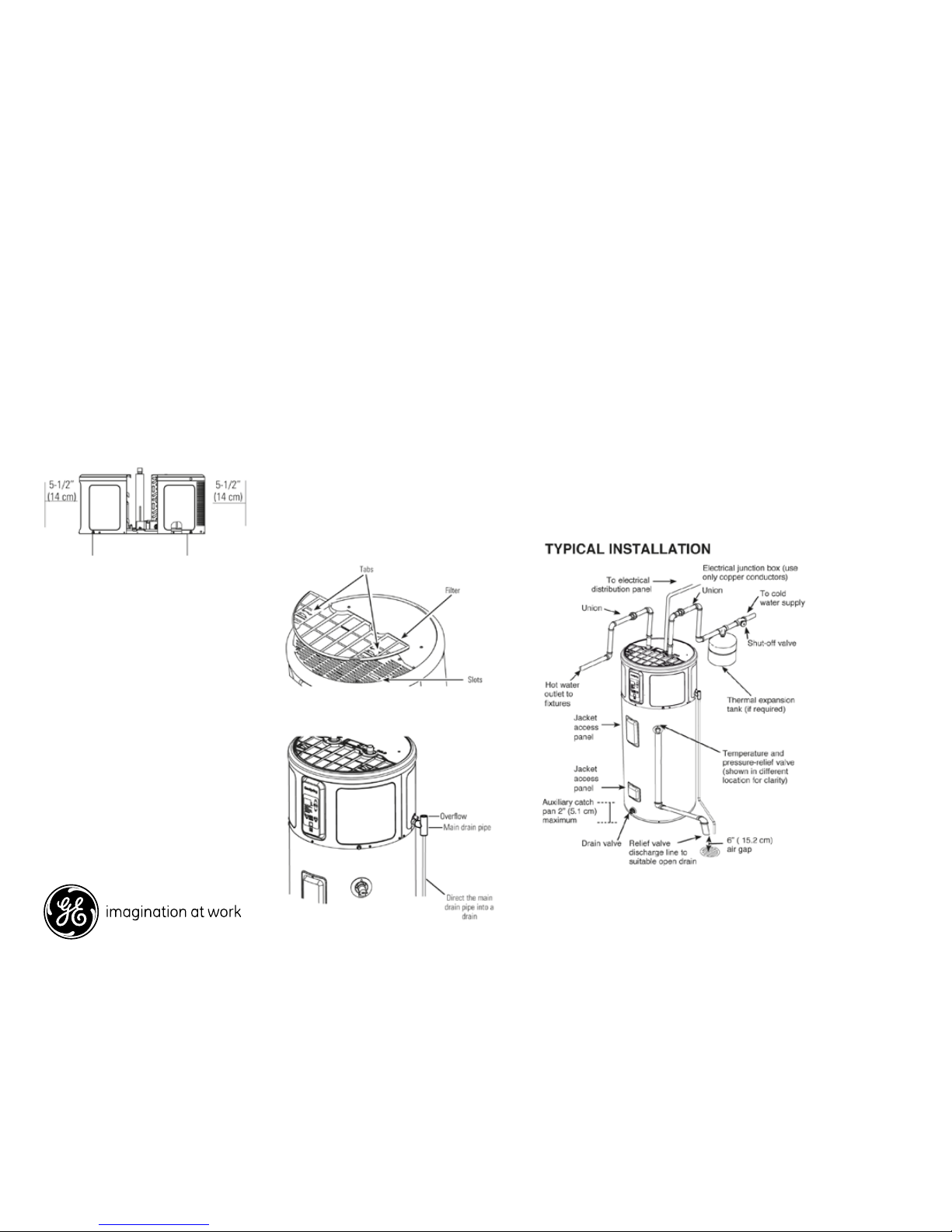
Water Supply Connections: Refer to the illustration below for suggested
typical installation. The installation of unions or flexible copper connectors
is recommended on the hot and cold water connections so that the water
heater may be easily disconnected for servicing if necessary. The HOT and
COLD water connections are clearly marked and are 3/4” NPT on all models.
Note: Install a shut-off valve in the cold water line near the water heater.
This will enable easier service or maintenance of the unit later.
IMPORTANT: Do not apply heat to the HOT or COLD water connections.
If sweat connections are used, sweat tubing to adapter before fitting the
adapter to the cold water connections on heater. Any heat applied to the
hot or cold water connection will permanently damage the dip tube.
Dimensions and Installation Information (in inches)
Front & back clearance requirements: A 7” clearance is
recommended with a minimum of 5-1/2” air space between any
object and the front and back of the water heater and 7” on each
side. Clearance is needed to allow for removal of the front and back
covers in the event service is needed.
Condensate drain required: A primary
drain pipe must be installed at the top right
side of the water heater. The primary drain
is intended to carry all condensate away.
Top filter removal clearance
requirements: A minimum 6” clearance is
required at the top of the water heater to
pull the filter up and remove it for cleaning.
It is critical that the hot and cold water
plumbing and the electrical connections do
not interfere with the removal of the filter.
Above illustration intended for dimensional reference only.
Refer to photograph for actual product appearance.
 Loading...