

Page 1
GE Oil & Gas
H Series compressors
High-speed reciprocating compressors for natural gas applications
Our H Series compressors (formerly models HPD, HPDD, HPSS, HPDS)
are designed to run continuously for extended periods of time while
unattended. These high-speed units forgive non-reversals through
unique wrist-pin needle bearing design. GE’s comprehensive line-up of
double-acting and stepped cylinders offer maximum staging flexibility.
A workhorse in field gas applications, the H Series can also provide up
to 6,000 psig for CNG vehicle refueling. The compact, packager-friendly
design features a “through shaft” fan adapter that allows the cooler to
be driven by the pump end of the compressor, shortening overall skid
size, and simplifying the piping design.
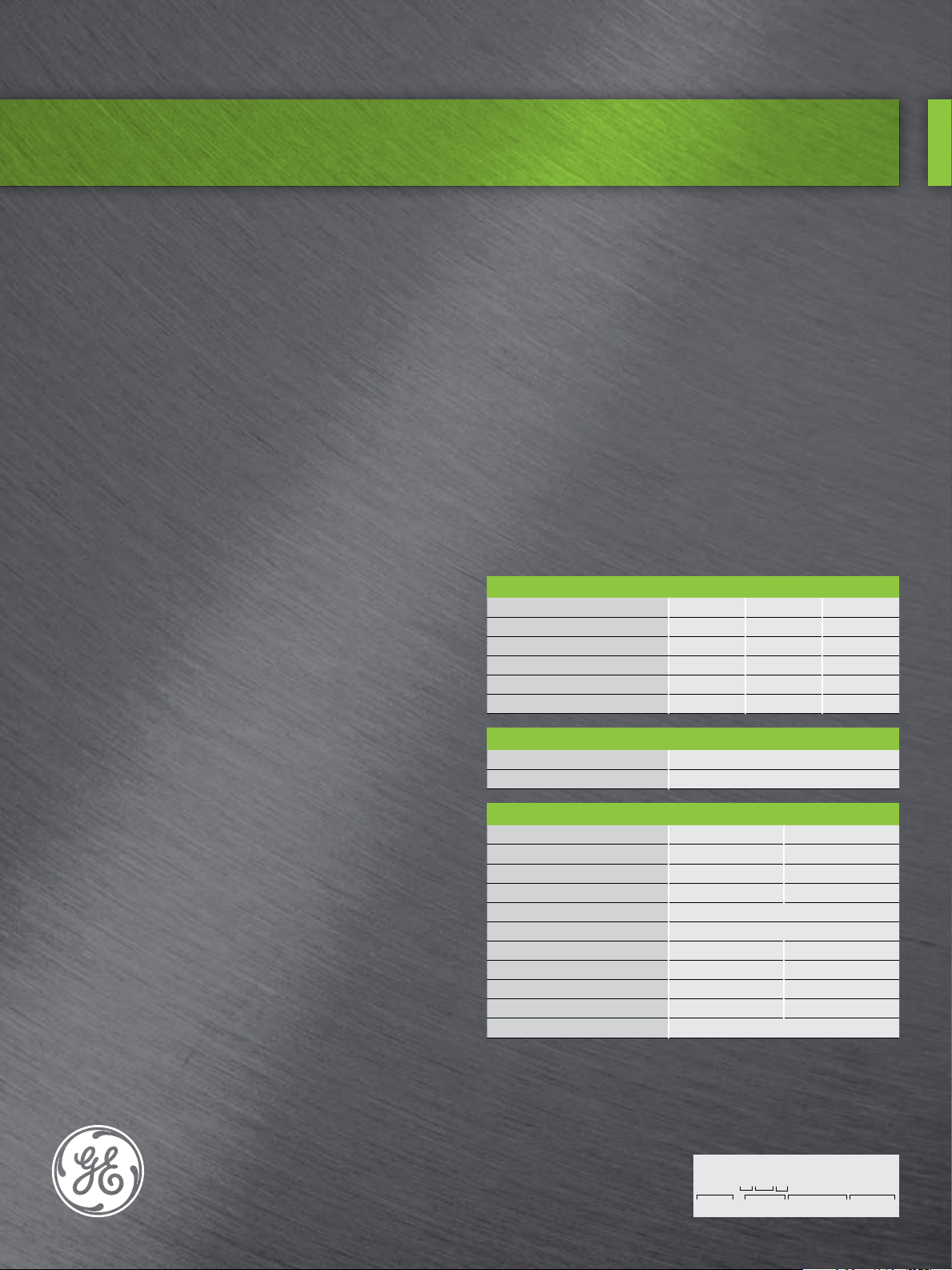
Performance features
Type
Horizontal balanced opposed, one, two or four throws with double
acting and/or stepped cylinder sets to provide up to four stages of
compression.
Frame
Heavy-wall, one-piece alloy iron casting with reinforcing ribs. Removable
alloy iron crosshead guides are surrounded by large cooling passages.
Crankshaft
Forged-steel design has integral counterweights and force-lubricated
tri-metal sleeve type main bearings.
Cylinders
A wide range of gas-cooled cylinder options is available. Cylinder
arrangements include double-acting, tandem, and stepped-piston
designs. Non-lube designs are available for special applications.
Cylinders are available with MAWP up to 6,000 psig.
Compressor valves
Steel valve seats and guards; MTX or HTCX valve plates are standard.
Valve springs, lifts and plates can be tailored to meet your performance
conditions.
Compressor lubrication
Gear type lube oil pump is driven by the crankshaft. Lubrication system
includes a non-bypassing, spin-on lube oil filter, oil pump relief valve and
thermostat.
Packing and cylinder lubrication
Integral single-pump force-feed lubricator contains a block distribution
system, a cycle indicator and a no-flow shutdown switch. Stainless
steel tubing includes plated fittings piped to the cylinders and packing.
Lubrication feed rate is fully adjustable.
Standard testing
Compressor mechanical run test, hydrostatic test of all cylinders and
post-test inspection meet GE’s high standards.
Standard accessories
Specialized tools, where applicable, are included in the toolbox.
Optional items
Variable-volume clearance pockets, CSA or XP no-flow switches and
vibration switches, export boxing, immersion oil heaters, flywheels, drive
couplings, oil coolers and fan drives.
Throw configurations
Compressor throws
Max. BHP (kW)
Frame weight lbs (kg) dry*
Frame length inches (cm)*
Frame width inches (cm)*
Frame height inches (cm)
1
100 (75) 200 (149) 400 (298)
1,050 (476) 1,050 (476) 2,350 (1,066)
26.3 (66.8) 26.3 (66.8) 57.6 (146.3)
49.5 (125.7) 49.5 (125.7) 49.5 (125.7)
28.9 (73.4) 28.9 (73.4) 25 (63.5)
2 4
Stroke configuration
Stroke inches (mm)
Max. rated speed (rpm)
3.0 (76.2)
1,800
Piston/piston rods
Hard anodized aluminum alloy or cast iron pistons. Weight is precisely
controlled during manufacturing to eliminate the need to match parts
in the field. Carbon-filled Teflon piston rings are standard for most
applications. Piston rods are 4140 steel with rolled threads. Full-floating
vented sealing and wiper packing.
Connecting rods
Ductile iron with precision insert type bearings on crank end and roller
bearings on pin end.
Crossheads
One-piece ductile iron crossheads have babbitted faces, cast iron
crosshead guides and steel crosshead pin.
Heavy duty running gear
Rod load - tension
Rod load - compression
Combined rod load
Piston rod diameter
Crankshaft material
Connecting rod material
Crankpin bearing diameter
Crankpin bearing width
Main bearing diameter
Main bearing width
Connecting rod pin
* without cylinders F.S. = Forged Steel D.I. = Ductile Iron
10,000 lbs-f
10,000 lbs-f 44.48 kN
20,000 lbs-f 88.96 kN
1.125 inches 28.6 mm
3.25 inches 82.6 mm
1.5 inches 38.1 mm
3.0 inches 76.2 mm
1.875 inches 47.6 mm
44.48 kN
F.S .
D.I.
Roller bearing
Model nomenclature
H304 = H 30 4
Model = Frame Stroke (in) Throws
Page 2
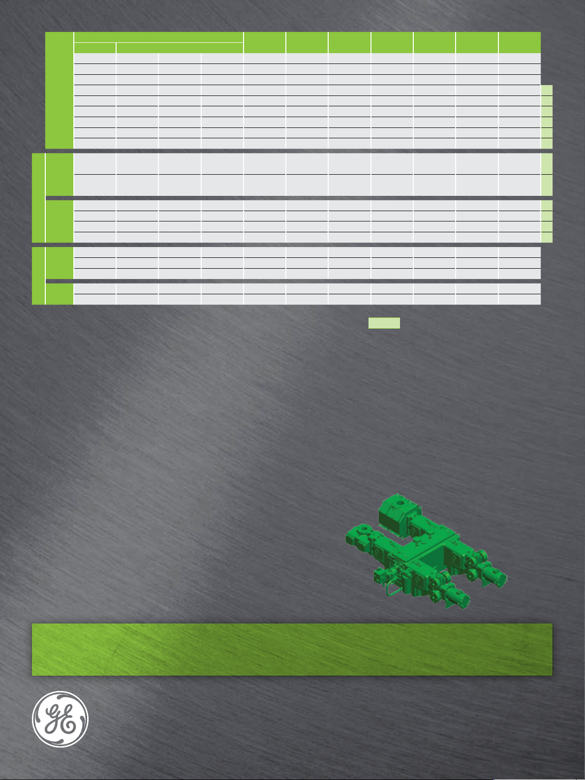
Cylinders for the H Frames
Series Cylinder bore - inches
H30 2.50 3 1,440 Gas D.I. 1.5 1,500 4 No
H30 2.50 3 1,250 Gas D.I. 1.5 600 4 No
90 3.50 1,725 Gas D.I. 2 1,500 4 Yes
H30 3.50 4 1,250 Gas D.I. 3 600 4 Yes a
H30 4.50 5 1,250 Gas D.I. 3 600 4 Yes a
Double acting
H30 5.50 1,000 Gas D.I. 3 600 4 Yes a
H30 6 6.50 500 Gas D.I. 4 300 4 Yes b
H30 7.50 8 500 Gas D.I. 4 300 8 Yes b
H30 8 9 300 Gas D.I. 4 300 8 Yes b
H30 2.50 3 1,250 Gas C.I. 1.5 600 2 No c
MAWP
PSIG
Cylinder
cooling
Material
Flange
dia inch
Flange
rating PSIG
Valves VVCP
Crank end
Stepped
Head and
Tandem (CNG)
L = Nitrided Liner - field replaceable D.I. = Ductile Iron SAHE = Tandem cylinder - Single Acting Head End a, b, c, etc. Designates cylinders having identical XYZ flange
NL = No Liner F.S. = Forged steel SACE = Tandem cylinder - Single Acting Crank End dimensions to assist interchangeability and package
C.I. = Cast Iron piping standardization
(1) The 1.25" piston can be trimmed to add 14% or
25% additional clearance
(1) The 1.50" piston can be trimmed to add 10% or
20% additional clearance
Designed for flexibility
• The H Series is backed by 100 years of GE compressor design
experience
• Part of a complete line of reciprocating compressors featuring
advanced technology and work-proven designs
• Many cylinders have identical X, Y, and Z flange locations, allowing
packages to be reconfigured without any changes to the piping and
bottles
H30 3.50 4 5 1,250 Gas C.I. 1.5 600 2 No c
single acting
H30 4 5 1,250 Gas D.I. 1.5 600 2 Yes d
H30 5.50 750 Gas D.I. 1.5 600 2 Yes d
H30 6.50 7.50 500 Gas D.I. 3 300 4 Yes e
single acting
H30 8 300 Gas D.I. 3 300 4 Yes e
H30 2.50 3 3,500 Gas F.S. 1 6,000 2 No
H30 2.50 3 2,500 Gas D.I. 1.5 1,500 2 No
SACE
H30 3.50 4 3,500 Gas F.S. 2 6,000 2 No
H30 1.25 1.50 6,000 Gas F.S. 1 6,000 1 No
SAHE
H30 1.75 2 6,000 Gas F.S. 1.25 6,000 1 No
Operating benefits
• Compressor is easily reconfigured to meet your changing
requirements
• Reduces lifecycle cost and increases production
• Reduces required inventory of machinery and spare parts
• Higher efficiency, lower fuel or electricity consumption
• Lower cost of reconfiguration
• Greater utilization of driver power over a wide range of conditions
• Over 18,000 GE high-speed reciprocating compressors have been
built to date
All GE high-speed reciprocating compressors are packaged, serviced
and maintained by a worldwide network of authorized packagers and
distributors.
Compressor Sales
HSR_Sales@ge.com
T +1 713 683 2400
24 Hour Technical Support
HSR_Support@ge.com
T +1 832 978 9780
GE imagination at work
OEM Replacement Parts
OilGasTeamBox@gexpro.com
T +1 866 565 2303
4425 Westway Park Blvd
Mail Stop 3
Houston, TX 77041
geoilandgas.com/hsr
© 2013 General Electric Company. All rights reserved.
GE_HSRC_H_FS-012413
 Loading...