

Page 1

,
GEK-36150
,r
O,P,ERATOR'S
'.
~
'
/MANUAL
GENERAL
fl
ELECTRIC
Page 2

The
information
contained herein does
not
purport
to
cover
all details
or
variations in
equipment
nor
to
provide
for
every
possible contingency
to
be
met
in connection
with
installation,
operation,
or
maintenance. Should
further
in-
formation
be desired
or
should particular
problems
arise
which
are
not
covered
sufficiently
for
the purchaser's pur-
poses,
the
matter should
be
referred
to
General Electric
Company, USA.
TermiNet
is a trademark
of
General Electric Company, USA
©Copyright
General Electric Company, USA 1973
Page 3
TermiNet
300
and
Operator's
1200 Printers
Manual
- GEK-36150
Printed July, 197 4 (SM)
Page 4

Page 5
GEK-36150
PREFACE
This manual shows
the
operator
how
the
TermiNet Printers are operated. Sections 1 through 5
describe what
the
controls and indicators do,
the
operation
of
the
keyboard,
the
loading
of
paper
and ribbon, and
other
information pertaining
to
the
operation and care-of
the
TermiNet Printer.
Because of
the
many communication systems
that
exist, no
attempt
is
made
to
show
how
the
TermiNet Printer may be used
in
a specific system. Consult your supervisor
or
application
specialist for special instructions on how
to
use
the
TermiNet Printer with
your
communications
system. Section 6
is
primarily for
the
application specialist who must know certain operating
characteristics
of
the
TermiNet Printer
in
order
to
understand how it should operate
in
your
communications system.
This manual covers
both
the
TermiNet
300
and 1200 Printers. Information
that
pertains only
to
a
specific model Printer
will be identified.
The term
"jumper"
will appear occasionally in
the
following text. Basically,
the
removal or
installation of a jumper
is
an optional wiring change
that
will change particular operating
characteristics of
the
TermiNet Printer. Most jumpers can be installed and removed by a TermiNet
Printer serviceman
at
the
TermiNet Printer site.
Because many TermiNet Printer
problems are simple and can be easily avoided
or
corrected
by
the
operator, read Section 5, "TAKING CARE OF YOUR TermiNet PRINTER," before calling for
service. You may avoid an unnecessary interruption
of
your
operation and an unnecessary service
call.
In
most
cases,
the
word
"Printer"
will be used instead
of 11TermiNet Printer" in
the
following text.
Preface
iii/iv
Page 6

Page 7
GEK-36150
TABLE OF CONTENTS
Table
of
Contents
SECTION 1
SECTION 2
SECTION 3
SECTION 4
INTRODUCTION
PREPARING THE PRINTER FOR OPERATION
Paper
Installation . . . . • . . . . . . . . . . . . . . . . . . . . . . . . . . . . . .
Paper
Required . . . . • . . . . . . . . . .
Ribbon Required
Ribbon
OPERATION
Switches, Controls,
Audlble Indicators
Keyboard Operations . . . . . . . . . . . . • . . . . . . . . . . . . . . . . . . .
Interrupt Conditions
Escape
Horizontal Tabulation
Vertical Tab
Split Platen Printer . . . . . . . . . . . . . . . . . . . . . . . . . . . . . . . . . 3-10
OPTIONS
Answerback
Automatic Answerback . . . . . . . . . . . . . . . . . . . . . . . . . . . . . . .
Automatic Carriage Return . . . . . . . . . . . . . . . . . . . . . . . . . . . . .
Automatic Motor Control
High
Line Control . . . . . . . . . . . . . . . . . . . . . . . . . . . . . . . . . . . . .
Parity Error Detection . . . . . . . . . . . . . . . . . . . . . . . . . . . . . . . .
Red/Black Ribbon Option
Transparency
Installation
Sequence
AND
Speed
...................................
.................................
and
Indicators . . . . . . . . . . . . . . . . . . . . . . . . .
..................................
.................................
and
Control
and
Form
ACCESSORIES
......................................
Transmission ·
Switch
.............•..................
Codes
.............•..................
Feed
(VTFF)
..............................
.....................
.............................
."
. . . . . . . . . . . . . . . . . . . . 2-5
. . . . . . . . . . . . . . . . . . . . . . . . 3-8
.·
......................
-
........
2-1
2-6
2-6
3-1
3-1
3-1
3-3
3-9
3-9
4-1
4-1
4-1
4-1
.4-1
4-1
4-1
4-2
.4-2
SECTION 5
SECTION 6
TAKING
Things
Cleaning the Printer
Replacing Pushbutton Lamps . . . . . . . . . . . . . . . . . . . . . . . . . . . .
Avoiding Unnecessary Service
TermiNet PRINTER OPERATING CHARACTERISTICS
Data Transmission
CARE OF YOUR TermiNet PRINTER
to
Remember
Interface
Speeds
Character Composition . . . . . . . . . . . . . . . . . . . . . . . . . . . . . . 6-3
ASC
TermiNet Character
......................................
........................................
11
Code
.•...............•...............
.................................
Calls
........................
and
Reception
. . . . . . . . . . . . . . . . . . . . . . . . . . . . . . . . . . . .
Codes
... ; .....................
............................
Continued
5-1
5-1
5-1
5-1
6-1
6-1
6-3
6-3
6-4
v
Page 8

Table
of
Contents
GEK-36150
SECTION 6 (Continued)
Timing Characteristics and
TermiNet
TermiNet
Using your Local TermiNet Paper Tape Accessory, Printing
or Transmitting
Using
A1
Using
Accessory (TCA) A3
TABLE
the
TermiNet
and A2 Models
the
TermiNet 1200 Printer with
OF CONTENTS (Continued)
Fill Characters
300
Printer
1200 Printer
to
..............................
..............................
a Remote Printer
300
Printer with
...............................
Model . . . . . . . . . . . . . . . . . . . . . . . . . . 6-14
.................
.....................
the
Cassette Accessory (TCA),
the
TermiNet Cassette
Locally
·
...
6-5
6-5
6-8
6-12
6-13
vi
Page 9

GEK-36150
Accessories, Options and
...............
Accessory, Magnetic Tape Cassette (TCA)
Accessory, Paper Tape
ALARM (Indicator)
ALL
CAPS (Switch)
Answerback
.....................
Answerback, Automatic
................
..............
.................
...............
...
3-2,3-4
4-1
.4-2
4-2
3-2
.4-1
4-1
Anti-Curl Device . . . . . . . . . . . . . . . . 2-2,2-3
ASC
11
Code . . . . . . . . . . . . . . . . . . . . . . 6-3
Audible Indicators
AUTO
L.
F.
(Switch)
Automatic Answerback . . . . . . . . . . . . . . .
Automatic Carriage Return
Automatic Motor Control . . . . . . . . . . . . . .
BS
(Backspace) Key
Carriage Return, Automatic . . . . . . . . . . . . .
Character Codes, TermiNet
..................
.................
.............
.................
.............
3-1
3-2
4-1
4-1
4-1
3-7
4-1
6-4
Character Composition . . . . . . . . . . . . . . . . 6-3
Characters, Printable . . . . . . . . . . . . . . . . .
Character Spacing, Horizontal
Cleaning
Code, ASCII
the
Printer . . . . . : . . . . . . . . . . .
......................
Codes, Escape Sequence and
Codes, TermiNet Character
............
Control . . . . . . . . 3-8
.............
1-1
1-1
5-1
6-3
6-4
Control Codes, Escape Sequence and . . . . . . . . 3-8
Panel
Control
.....................
Controls and Indicators, Switches
Copy
..........................
Cover Interlock (Switch)
...............
.........
1-Q
3-1
1-1
3-5
Cover Latch . . . . . . . . . . . . . . . . . . . . . . 3-5
Cover Release Latch
Cover, Top
.......................
Covers, Tractor
CTL (Control)
.................
....................
Key
..................
Data Transmission and Reception
DEL (Delete) Key
Dimensions, Paper Hole
Dimensions, Ribbon and
..................
...............
SpQol
.........
...........
1-2
1-2
2-3
3-7
6-1
3-7
2-6
2-7
INDEX
Index
11
11
Fill
Character Chart
Printer, Time Delay and
11
11
Fill
Character Chart for TermiNet 1200
Printer, Time Delay and
Fill characters, Timing Characteristics and
FORM FEED (Switch)
Feed, Vertical Tab and (VTFF)
Form
for
TermiNet
.............
.............
................
300
.......
.....
6-6
6-9
6-5
3-4
3-9
Forms Tractor . . . . . . . . . . . . . . . . . . 1-2,2-3
HERE
IS
(Switch)
Speed Transmission (300 Printer)
High
Horizontal Character Spacing
Horizontal Tabulation
HT
(Horizontal Tab} Key
..................
............
................
..............
......
3-2
4-1
1-1
3-9
3-7
Indicator,
ALARM . . . . . . . . . . . . . . . . . . . 3-2,3-4
Print Position . . . . . . . . . . . . . . . . 1-2,3-2
READY
...................
3-2,3-4
Indicator/Switch,
INTERRUPT
LOCAL
MOTOR
MOTOR
ON
LINE
STANDBY
................
.......................
OFF
...................
ON
....................
......................
.......
·
..............
3-2,3-4
3-2
3-4
3-4
3-2
3-2
Indicators,
Audible . . . . . . . . . . . . . . . . . . . . . . .
Switches, Controls, and . . . . . . . . . . . . . .
3-1
3-1
Indicators and Switches,
KSR
Printer . . . . . . . . . . . . . . . . . . . . 3-2
RO
and SR Printers
INHIBIT (Switch)
Install
at
ion, paper . . . . . . . . . . . . . . . . . .
Installation, Ribbon
Interface . . . . . . . . . . . . . . . . . . . . . . . .
Interface Connections . . . . . . . . . . . . . . . .
................
..................
.................
3-4
3-2
2-1
2-6
6-1
6-1
Interlock Switch, Cover . . . . . . . . . . . . . . . 3-5
INTERRUPT (Indicator/Switch)
Interrupt Condition Table
Introduction
......................
.......
..............
3-2,3-4
3-3
1-1
Error Detection, Parity . . . . . . . . . . . . . . . .
ESC
(Escape) Key
..................
Escape Sequence and Control Codes
External Paper
Handler . . . . . . . . . . . . 1-2,2-5
External Paper Handler, Paper
External Paper Rack . . . . . . . . . . . . . . . .
Fan-Fold Paper Widths
FF (Form Feed) Key
................
.................
........
Installation
....
4-1
3-7
3-8
2-5
.2-3
2-6
3-7
Keyboard . . . . . . . . . . . . . . . . . . . . . . . 1-2
Keyboard Operations . . . . . . . . . . . . . . . . .
3-1
Key,
BS
(Backspace)
CTL (Control}
DEL (Delete)
ESC
(Escape}
FF
(Form Feed)
..................
...................
...................
...................
..................
3-7
3-7
3-7
3-7
3-7
vii
Page 10

Index
INDEX {Continued)
Key (Continued)
HT
(Horizontal
LF (Line Feed)
(Shift Lock)
LOK
RPT (Repeat)
RETURN
SHIFT
VT (Vertical Tab)
Operation
Keys,
Knob, Platen . . . . . . . . . . . . . . . . . . 1-2,3-5
Lamps,
Latch, Cover
Lever, Paper
LF (Line Feed) Key
Line
LINE
Line Lengths,
LINE SPACE (Switch)
Line Spacing, Vertical
LOCAL
LOK (Shift Lock) Key
Replacing
Control
FEED
(Indicator/Switch)
Tab)
.•.............
..................
.................
................
..............
.......................
.................
....................
Pushbutton
......................
Release
. . . . . . . . . . . . . . . . . . . . . . 4-1
(Switch)
Print
........
.................
................
..................
.............
................
.............
................
- -
............
- . . . . . 1-2,3-5
......
-
..
3-2,3-4
3-7
3-7
3-7
3-7
3-7
3-7
3-7
3-7
5-1
3-5
3-7
3-4
1-1
1-1
3-2
3-7
.
Magnetic
Manual Controls, Switch Locations
Motor
MOTOR
MOTOR ON (Indicator/Switch)
Tape
Control,
OFF
Cassette Accessory (TCA)
and
Automatic
(Indicator/Switch)
..............
..........
..........
.....
4-2
. . . . . . 3-5
4-1
3-4
3-4
GEK-36150
Paper
Tape
Accessory
Tape
Paper
Paper
Paper Widths, Fan-Fold
Parity Error
Platen
Power
Preparing
Print
Print
Printable Characters . . . . . . . . . . . . . . . . .
Printing Speeds
RATE (Switch) . . . . . . . . . . . . . . . . . 3-2,3-4
READY
Reception, Data Transmission and . . . . . . .
Red/Black
Release Lever, Paper
Replacing
RETURN Key
Ribbon
·Ribbon
Ribbon
Ribbon, Red/Black
Ribbon Required
RPT
Rubber
Accessory, Using Printer
Tube
Line Lengths
Position Indicator . . . . . . . . . . . . 1-2,3-2
(Repeat)
. . . . . . . . . . . . . . . . . . . . . . 2-2
Detection
Knob
. . . . . . . . . . . . . . . . . . . 1-2,3-5
ON
Switch
the
Printer
(Indicator)
Ribbon
Pushbutton
.....................
and
Spool
Installation
Out
Sensor
Key
Feet
- Paper Rack
.............
with
...............
. . . . . . . . . . . . . . . .
. . . . . . . . . . . . . . . . 1-2,3-5
for
Operation
..................
....................
..............
Option
Dimensions
...................
..............
.................
Lamps . . . . . . . . . .
..................
..................
Option
..................
..............
.........
...........
.............
4-2,6-12
....
3-2,3-4
..
..
6-12
2-6
4-1
2-1
1-1
1-1
1-1
6-1
4-2
3-5
5-1
3-7
2-7
2-6
2-7
4-2
2-6
3-7
2-3
ON LINE (Indicator/Switch)
Operating Characteristics,
OPERATION
Operation
Operation,
Operations, Keyboard . . . . . . . . . . . . . . . . 3-1
Options
Panel, Control
Paper Handler, External . . . . . . . . . . . . 1-2,2-5
Paper Handler, External, Paper Installation
Paper Hole Dimensions (Fan-Fold)
Installation
Paper
Paper Pan . . . . . . . . . . . . . . . . . . . . . . . 2-3
Paper Rack, External . . . . . . . . . . . . . . . . . . 2-3
Paper Rack,
Paper Release Lever . . . . . . . . . . . . 1-2,2-5,3-5
Out
Paper
Paper
Out
Paper Required
Paper
Roll Dimensions
Shield
Paper
Paper
Shield Switch
.....................
Keys . . . . . . . . . . . . . . . . . . . . 3-7
Preparing
and
Accessories . . . . . . . . . . . . . . .
Rubber
Switch (External) . . . . . . . 2-3,2-5,3-6
Switch (Internal)
the
.....................
...................
Feet
....................
......................
.................
............
TermiNet
Printer for . . . . . . . .
..............
................
..........
Printer
.........
....
....
2-2,3-5
3-2
6-1
3-1
2-1
4-1
1-2
2-5
2-6
2-1
2-3
2-5
2-5
1-2
3-5
Sensor,
Shield, Paper . . . . . . . . . . . . . . . . . . .
SHIFT
Space Bar . . . . . . . . . . . . . . . . . . . . . . . 3-7
Spacing, Horizontal Character
Spacing.Vertical Line
Speed (Data Transmission
Speeds, Printing . . . . . . . . . . . . . . . . . . . .
Split
STANDBY (Indicator/Switch)
Switch,
Ribbon
Key
Platen
ALL
AUTO L. F. .
Cover
FORM FEED
HERE
INHIBIT
LINE FEED
LINE SPACE
Paper
Paper
Paper
Out
.................
......................
............
.................
and
Reception)
Printer
CAPS
Interlock . . . . . . . . . . . . . . . . . . 3-5
IS
Out
Out
Shield
.................
.....................
...................
...................
......................
......................
....................
................
(External)
(Internal)
....................
..........
............
...........
2-7
..
1-2
3-7
1-1
1-1
.....
6-3
1-1
3-10
3-2
3-2
3-2
3-4
3-2
3-2
3-4
3-2,3-4
2-3,2-5,3-6
2-2,3-5
3-5
viii
Page 11
GEK-36150
Index
Switch (Continued)
Power On
RATE
TRANSPARENCY ·
....
...........
.
.
...
.
Switch/Indicator,
INTERRUPT
LOCAL
MOTOR
MOTOR ON
ON
LINE
STANDBY
................
.......................
OFF
...................
....................
......................
.....................
Switches and Indicators,
KSR
Printer
RO
and SR Printers . . . . . . . . . . . . . . . . 3-4
Switches, Controls, and Indicators
....................
.........
Switch Locations and Manual Controls
Tabulation, Horizontal
Taking Care
of
your
Tape Accessory, Paper
Tape Cassette Accessory (TCA)
Tape Cassette Accessory (TCA), A
Models, Using
................
TermiNet Printer
................
the
300
With,
....
1"
and A2
..........
.......
.4-2,6-13,6-14
Tape Cassette Accessory (TCA), A3 Model,
Using
the
1200
Printer With,
..........
INDEX
......
1-2,3-5
3-2,3-4
3-2,4-2
3-2,3-4
3-2
3-4
3-4
3-2
3-2
3-2
3-1
3-5
3-9
5-1
4-2
6-13
6-14
(Continued)
Tension Limiter
TermiNet Character Codes
TermiNet Printer Operating Characteristics
Time Delay and 11Fill
TermiNet
Time Delay and 11Fill
TermiNet
Timing Characteristics
Timing Characteristics and Fill Characters,
TermiNet
Timing Characteristics and
TermiNet
Top
Tractor Covers
Tractor, Forms . . . . . . . . . . . . . . . . . 1-2,2-3
Transmission and Reception, Data
Transmission, High Speed (300 Printer)
TRANSPARENCY (Switch)
Vertical Line Spacing
Vertical Tab and Form Feed (VTFF)
VT (Vertical Tab) Key
Cover
....................
11
Character Chart for
300
Printer
1200
...............
11
Character Chart for
Printer
and
300
Printer
1200
...............
Printer
.......................
....................
.................
................
..............
..............
Fill Characters
Fill Characters,
..............
.........
..........
.......
.....
.....
....
3-2,4-2
2-2
6-4
6-1
6-6
6-9
6-5
6-5
6-8
1-2
2-3
6-1
.4-1
1-1
3-9
3-7
ix/x
Page 12

Page 13

GEK-36150
Introduction
SECTION 1
INTRODUCTION
Your TermiNet Printer
is
a high speed data
communications
printer
used primarily for
communicating with computer systems or
other
printers. The TermiNet Printer
is
compact for
operation
on
a desk
top
or
on
its optional Pedestal.
Operation
is
quiet compared
to
similar equipment.
The Printer can print and transmit information
that
is
received from its keyboard or from an external source
(for
example, a paper
tape
reader).
NOTE
For convenience, reference
to
the TermiNet
Printer,
in
most cases, will be "Printer".
Your Printer
will be one of
two
basic models; the
TermiNet
300
or TermiNet
1200
Printer (Figures
1-1
and 1-2). The TermiNet
300
and 1200 Printers print
maximum speeds of
30
and 120 characters per second
respectively.
The
KSR
(Keyboard, Send, and Receive) version of
the Printer has a keyboard similar
to
a standard office
typewriter. The
KSR
Printer can
print
and transmit
information generated
locally by the keyboard or a
local device (e.g., paper tape reader}.
It can receive
and print information from a remote terminal,
computer, or
other
communication device. ·
NOTE
When a
KSR
Printer
is
combined with a
recording and reading device such as a paper
tape punch and reader,
the
combined
configuration
is
normally called an ASR.
The SR (Send and Receive) version of
the
Printer has
no keyboard. The
SR Printer operates similar
to
the
KSR
except for
the
absence of the keyboard.
The
RO
(Receive Only) version
of
the Printer has no
keyboard and can print received information only.
Although this manual
is
written primarily for the
KSR
Printer,
the
SR and
RO
Printers operate
in
a
similar manner except for
the
major differences
previously explained.
The
general operating characteristics of the TermiNet
Printer are
as
follows:
PRINTABLE
CHARACTERS
All
of
the
94
printable characters
in
the
American
Standard Code for
Information Interchange (ASCII)
can
be
printed by the TermiNet Printer.
PRINTING SPEEDS
300
Printer,
the
standard
front
panel
RA
TE
switch
will select speeds
of
10, 15, and
30
characters per second (cps). An optional
speed
of
20
cps
is
available
as
a substitute for
one of the standard speeds.
1200 Printer, the standard
front
panel RATE
switch
will select speeds of
10;
30, or
120
characters per second. Optional speeds of 15,
20
or
60
cps are available
as
a substitute for
one
of the standard speeds.
HORIZONTAL CHARACTER SPACING
10 characters per inch (2.5 cm).
VERTICAL LINE SPACING
6 lines per inch (2.5 cm) with the LINE SPACE
switch in the
11111
position. 3 lines per inch (5.1 cm)
with
the
LINE SPACE switch
in
the
"2''
position.
PRINT LINE LENGTHS
300
Printer - 75,
80
or 118 print positions.
1200 Printer -
80
or 120 print positions.
COPY
The Printer
is
capable of handling up
to
a six-part
form set with a maximum form set thickness of
0.025
11
(0.64 mm). Recommended paper weights are:
1 part
2, 3 or 4
part
6
part
15 lb. paper
13.5
lb. paper, 8 lb. carbon
12
lb. paper, 8 lb. carbon
Multiple copies are only
possible with pin
or
tractor
feed paper.
1-1
Page 14

Introduction
GEK-36150
/ POWEFl SWITCH
PAPER
RELEASE
LEVER
PRINT
POSITION
INDICATOR
CONTROL
PANEL
RELEASE
LATCH
PKM-4007
Fiaure 1-1. TermiNet 300 Printer tKSR). Friction
Feed
PAPER
HANDLER
FORMS
TRACTOR
PKH-4005
i=igure
1-2. TermiNet 1200 Printer (KSR)
with
External
Paper
Handler
1-2
Page 15

GEK-36150
Preparing the Printer for Operation
SECTION 2
PREPARING THE PRINTER FOR OPERATION
PAPER
INSTALLATION
FRICTION
FEED (300 PRINTER)
a.
Press
the
Printer cover release latches and lift
cover (Figure
2-1
).
I WARNING I
POWER
IS
STILL
ON
WHEN THE COVER
IS
LIFTED. KEEP YOUR HANDS
ONLY
IN
AREAS NEEDED TO
INSTALL
THE
PAPER.
b.
Remove paper tube (Figure 2-2) from Printer.
c. Place the paper tube
in
the center of the new
paper
roll.
PLATEN
KNOB
d. Set the paper roll and tube
in
place.
e.
Lift the paper shield (Figure 2-1).
f. Feed the paper from the bottom of the
roll,
over the tension limiter, and under the platen
(Figure 2-3).
NOTE
It may be necessary
to
press the tension
limiter down while routing the paper under
the platen.
Make
certain
the
anti-curl device
(Figure 2-4)
is
positioned
in
the
middle of
the paper width.
g.
Push the Platen Knob (Figure 2-1)
in
and rotate
to
advance the paper.
PAPER
RELEASE
LEVER
in
the rear (normal) position
PAPER
SHIELD
....--RIGHT
COVER
RELEASE LATCH
PKM-4008
Figure 2-1. Paper Handling
2-1
Page 16

Preparing
the
Printer for Operation
GEK-36150
PAPER
TUBE
Figure 2-2. Paper Tube
PKM-4009
i.
To align the paper, move the Paper Release
Lever (Figure 2-1)
to
its forward (toward
the
keyboard) position and align
the
left edge of
the
paper with the vertical line on
the
paper
shield.
j.
Move
the Paper Release Lever
to
its most rear
(toward the
bustle) position.
PIN FEED (300 PRINTER)
a. Align the paper supply container, holder, etc.,
behind the Printer. The paper
supply should
be lower than the Printer's
top
surface.
b. Route the paper over
the
back of the Printer
toward the platen.
h.
Lower
the
paper shield carefully.
Do
not let
the
shield snap down.
c.
Insert the paper under the platen and align
paper holes with the sprocket pins.
2-2
ANTI-CURL
DEVICE
TENSION
LIMITER
PRESS
HERE
TO
RELEASE
LOW
PAPER
SWITCH
IF.
IN
LOCKED
POSITION
PRESS
DOWN
HERE
TO
"LOCK
OUT
11
LOW
PAPER
SWITCH
----
--
-
-
\
--
CD
PAPER OUT SWITCH IN LOCKED POSITION
-DEFEATS
ALARM -ENABLES
OPERATION
@ PAPER OUT SWITCH
IN
FULL
ROLL RANGE -
ENABLES
OPERATION
@ PAPER OUT SWITCH IN LOW PAPER
POSITION
PKM-4010
Figure 2-3. Paper Installation - Friction Feed
Page 17
GEK-36150
Preparing
the
Printer for Operation
l
PTM-3009
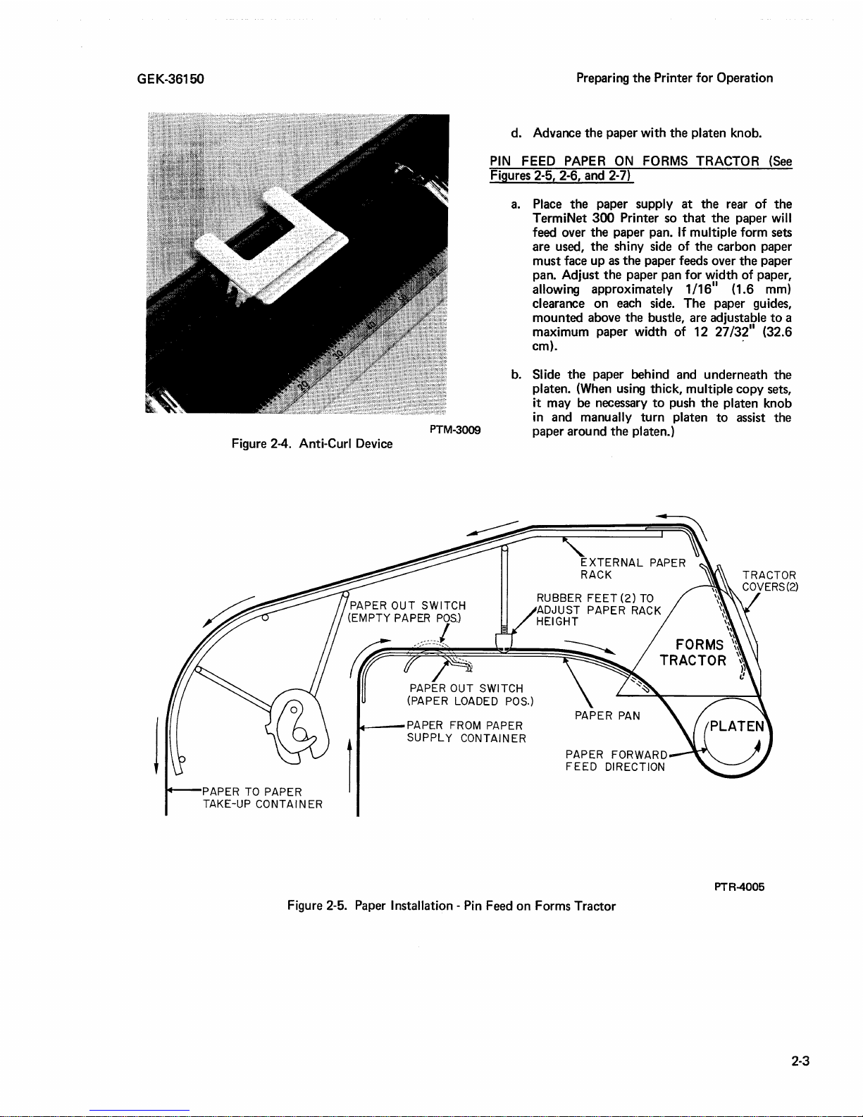
d. Advance the paper with the platen knob.
PIN
FEED PAPER
ON
FORMS TRACTOR (See
Figures 2-5, 2-6, and 2-7)
a.
Place
the
paper supply
at
the rear of
the
TermiNet
300
Printer so
that
the
paper will
feed over the paper pan.
If
multiple form sets
are used, the shiny side of the carbon paper
must face up
as
the
paper feeds over
the
paper
pan. Adjust
the
paper pan for width of paper,
allowing approximately
1/16
11
(1.6 mm)
clearance
on
each side. The paper guides,
mounted above the bustle, are adjustable
to
a
maximum paper width of 12 27
/32
11
(32.6
cm).
·
b.
Slide
the
paper behind and underneath the
platen. (When using thick, multiple copy sets,
it may be necessary
to
push
the
platen knob
in
and manually
turn
platen
to
assist the
paper around the
platen.)
Figure 2-4. Anti-Curl Device
PAPER TO
PAPER
TAKE-UP
CONTAINER
PAPER
OUT
SWITCH
(EMPTY
PAPER
POS.)
rr
/'
l
PAPER
OUT
SWITCH
(PAPER LOADED POS.)
w---PAPER
FROM PAPER
SUPPLY
CONTAINER
RUBBER
FEET
(2)
TO
ADJUST
PAPER
RACK
HEIGHT
PAPER
FORWARD
FEED
DIRECTION
Figure 2-5. Paper Installation - Pin Feed on Forms Tractor
PTR-4005
2-3
Page 18
Preparing the Printer for Operation
c.
Adjust the two tractors
on
the
forms tractor
assembly setting above and just behind the
paper shield by loosening the knurled knob
located behind each tractor.
Slide tractors
horizontally
tp
the
left
or
right as required
to
line up with the paper width being used. Lock
tractors
in
this position by tightening the two
knurled knobs.
d. Open the covers
on
the
tractors and fit the
holes in
the
edges of the paper over the
tractor pins
as
illustrated in Figure 2-6.
e.
Close covers
on
the
tractors and rotate platen
with
the
Platen Knob until
the
paper
is
over
the
top
of the external paper rack.
f.
Make sure
the
paper passes through
the
paper
out
switch housing located
to
the
left rear of
the
paper pan so
the
paper
out
switch
is
pressed by
the
paper. The paper
out
switch
senses when incoming paper
is
no longer at
the
top
of
the
bustle and causes an "Alarm"
condition. Approximately 16
11
(40.6 cm) of
paper remain available when the
11
Alarm"
occurs.
GEK-36150
PTR-3003
Figure 2-6. Fitting Paper Over Tractor Pins
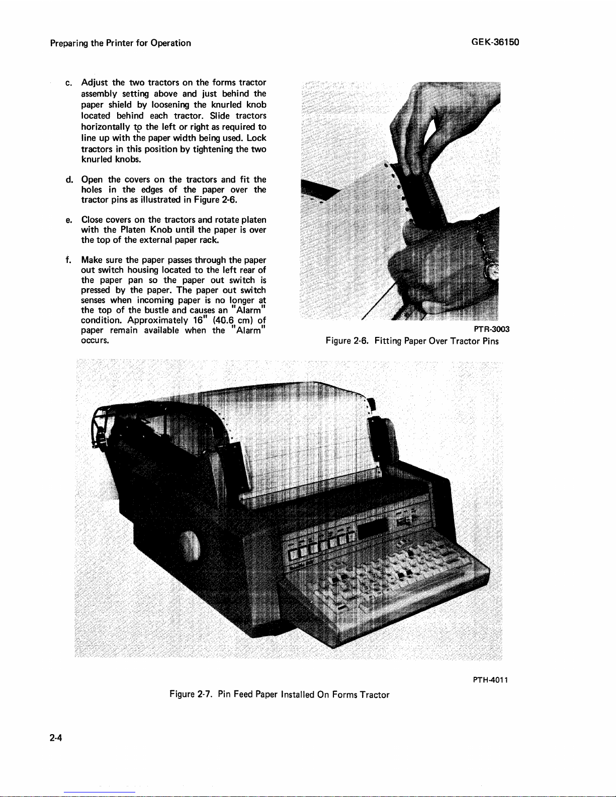
PTH-4011
Figure 2-7.
Pin
Feed Paper Installed
On
Forms Tractor
2-4
Page 19

GEK-36150
Preparing the Printer for Operation
EXTERNAL
PAPER
HANDLER
(OPTION)
Similar to Forms Tractor except
use
Figure
2-8
as
a
reference.
PAPER
REQUIRED
ROLL
(300 PRINTER)
Figure
2-9
shows the dimensions of the paper
roll
required for the Printer.
PAPER
OUT SWITCH
FOR
EXTERNAL
PAPER
EXTERNAL
PAPER
HANDLING SYSTEM-OPTIONAL
~TERNAL
FAN FOLD
PAPER
SUPPLY
FOR
PIN FEED
PLATEN
MACHINES
----.ARROWS
INDICATE ROUTE
FOR
FEEDING
PAPER
TRANSPARENT SHIELD
OPH-4003
Figure
2-8.
Paper Installation with External Paper Handler
1
••
l
2
.s
c\\J\)
coRE
S\Z.E
..
4cM)
8 7 /'\6'' l2
•.
'IJ\O'T\-\
Figure
2-9.
Paper
Roll
Dimensions
PTM-4025
2-5
Page 20

Preparing the Printer
SINGLE SHEET
A single
(12.7 cm) may
FAN FOLD
sheet
with
be
for
Operation
a minimum length
used
in Printers using paper rolls.
of
5 inches
~----"t'--
1
(6.35 MM)
GEK-36150
/4"
Your Printer may
consists
each
the Printer. A pin feed Printer
in one
tractor Printer can
(7.6 cm)
determine the
distance
Use
Paper
Multiple copy paper consisting
to
thick
of
either a platen having a row
end, or a forms feed tractor mounted on
of
the
to
across
"overall"
hole dimensions
five copies
may
be
have
a pin
feed
will
sizes
shown in the table. A forms feed
use
any paper
12 27/32 inches (32.6 cm). You
size
your
Printer
the
width
size
when ordering
are
not
exceeding 0.025 in. (0.64 mm)
used.
width
uses
of
the platen between pins.
shown in Figure 2-11.
of
option
of
pins around
use
fan-fold paper
from
by
measuring the
(see
Figure 2-10).
an
original
top
3 inches
and
WIDTH
I
which
of
can
up
I
1/2"
150
shows
(12.7 MM)
FS
Underwood
ribbon
5/32"
(39.6 MM)
Figure 2-11.
Replacement Ribbons must
type double spools. (Figure 2-12
·spool dimensions.) The following ribbons
recommended.
Columbia
Curtis Young DUO PAK, Nylon 44, Black
Medium
Labelon Underwood Scriptor Duet, Black
Medium,
Paper
Hole Dimensions
RIBBON REQUIRED
have
#3202-2005
#4
#430
Nylon
PTR-4007
and
are
PIN FEED PAPER WIDTHS
Pin-to-Pin Overall
11
(20.3 cm)
8
11
/2
(21.6 cm)
8 1
11
9
(22.9 cm) 9 1
11
11
/32
12
3
2-6
11
(7.6 cm)
(31.3 cm)
Split Platen - Right Hand
Figure 2-10. Fan-Fold
l
8
1/2
11
9
(22.9 cm)
/2
12
27
3
1/2
Paper
11
(21.6 cm)
11
(24.1 cm)
11
/32
(32.6 cm)
11
(8.9 cm)
PTR-4006
Widths
Buckeye #130-2070-115 Paquette, Black
Record
General Ribbon,
Computer Black,
Install
ink
technique shown pictorially
Figure 2-14.
On
certain the ribbon
platen
(metal tab
platen).
#5
G.
Heavy
RIBBON
ribbons
Printers
and
INSTALLATION
as
shown by Figure 2-13,
NOTE
with
a forms tractor,
is
not routed between the
the anti-snag device paper holder
holding the paper against the
E.
TermiNet 300, Silk,
by
steps
1 through 6 in
make
using
Page 21

GEK-36150
Figure 2-12. Ribbon
and
Spool Dimensions
Preparing the Printer
PTR-4008
for
Operation
1.
SLIDE
EMPTY SPOOL
RIBBON OUT SENSOR MUST
DO NOT
FORCE
UNWIND
TAPE
ON
SPOOL
ALREADY
RIBBON OUT
LEFT
ON . DO
ON
SENSOR
3.
HUB.
ENGAGE
NOT
SPOOL.
BEFORE
IN
DIRECTION
DOES
RIBBON INSTALLATION
SLOT.
OPERATING
NOT
INTERFERE
PRINTER
INCORRECT
OF
ARROW
CAN
PRINTER
TO
WITH PRINT
CAUTION:
BE
DAMAGED
INSTALLATION
2.
ROUTE
INSTALL
SPOOL TO TAKE OUT SLACK .
ONE SPOOL
ROTATE
INSURE THAT RIBBON
FINGERS.----_,
Figure 2-13. Ribbon Installation
DO
BELT
BY
RIBBON
AS
FULL
NOT
BY
SHOWN
SPOOL.ROTATE ONE
Will
TURN
FORCE)
HAND
AND
(ONLY
MANUALLY
(
\11
-
~
'
44(902924
PrR-3001
2-7
Page 22

Preparing the Printer for Operation
2-8
GEK-36150
Place
Empty
Spool
On
Hub
First
0
~\~~~t~~
,~J1R9~
"YVm·.
~f:l~~.r
on
Hub
Place
Full
Spool
On
Other
Hub
. Align Slot In Spool With
Sensor
On
Hub
.
;.
. . . .
,,,_,,
. .
·---........
PTR-4009
Figure 2-14. Ribbon Installation Procedure
Page 23

GEK-36150
Operation
SECTION 3
OPERATION
SWITCHES, CONTROLS,
AND
INDICATORS
Figures 3-1, 3-2, and 3-3 point
out
the
locations
of
the
switches, controls, and indicators and explain
their basic functions.
AUDIBLE
INDICATORS
Beep
tone
each time a key
is
pressed.
High
pitch
tone
when ALARM indicator
lights.
High
pitch
tone
when INTERRUPT indicator
lights.
High
pitch
tone
indicating near end
of
line
and end of line. The
tone
will sound
at
print
positions 67, 72,
110, and 112 on 75, 80,
118,
and 120 print position Printers
respectively. The
tone
will also sound after
the
last print position
of
the
Printer.
NOTE
The
volume
of
all
the
audible indicators
is
adjustable by
the
serviceman
if
the
preset
volume does
not
satisfy your particular need.
KEYBOARD OPERATIONS
The keyboard
is
similar
to
that
on a standard electric
typewriter. The keyboard has a total
of
62
keys
including
the
space bar, and
is
capable
of
generating
all
128
ASCII characters. The keys are electronically
interlocked
so
that
it
is
not
possible
to
generate
two
or
more codes simultaneously. A beep
tone
sounds
each time a key
is
pressed (with
the
exception
of
the
SHIFT, LOK, CTL, and RPT keys). Because actual
printing may
not
occur
at
the
same instant you press
a key (as with
most
typewriters),
the
beep
tone
allows
you
to
maintain your normal typing rhythm.
For descriptions
of
the
Printer operation keys, see
Figure 3-5.
3-1
Page 24

LOCAL · Lights whep prnssed, Starts
motor
and
onables' local Printer operation
but
does
not
al.low
the
transmission
or
reception of data.
STANDBY
~
· Ughts
when
pressed.
Tums
motor
oft
but
leaves electronics
i\.lmed
on
which enables
the
transmission
and
reception
of
data.
ON
UNE • Lights
When
pressed.
Tums
Printer
motor
on
.arid
enable~.
the
transmission and reception of
data.
READY·
Indicates data set
Is
ready
for
transmission.
Held
ofl
!f
INTER.RUPT
lamp
is
on
.
. 1200 Printer only - Used as
farnp
self test.
When· pre$sed,
all
lamps should light. The
HERE
lS
pushbutton ·does·
not
have a lamp.
ALARM • The ALARM lamp lights when the following alarm conditions occur (remains
on
until
the
alarm condition has been corrected):
Low paper or paper
out
Paper Shield
up
{not
on
forms tractor model)
Paper punch
out
of
paper or end
of
magnetic tape
in
"Write" mode if
in
optional
ASR configuration.
Problem
in
the Printer.
Also,
when the ALARM lamp lights, the following occurs:
An Alarm tone sounds
An
Interrupt
or
Break
is
automatically transmitted
to
alert
the
other end of
the
line
(if
on line)
The
motor
turns off
The following
are alarm conditions
that
do
not
light the ALARM lamp
but
sounds
the
Alarm tone, causes
an
Interrupt or Break
to
be transmitted, and turns off
the
motor.
Cover
up
(300 Printers only)
Undervoltage
to
Printer.
Print
belt
underspeed.
ALL
CAPS · When placed in
the
ON
position, all
alphabetic printing caused by the keyboard only will
be
upper
case.
AUTO
LF.
·When
in the ON position,
the
paper
is
advanced automatically when the RETURN
key
fa
pressed. (Has no effect
on
incomfng data.)
PKM-4011
Figure 3-1. Switches
and
Indicators, KSR Printer
G)
m
A
w
(J)
-
CJ1
0
Page 25

GEK-36150
CONDITION OF
INTERRUPT
LAMP
Unlit
Lit
CONDITION OF
INTERRUPT
LAMP
Unlit
Lit
TABLE3-1
INTERRUPT CONDITION
TABLE
RESULTS FROM PRESSING
INTERRUPT PUSHBUTTON
An
11
lnterrupt
11
or 11Break
11
signal
is
transmitted.
INTERRUPT lamp
does
not light.
1.
INTERRUPT lamp
goes
out.
2.
11
lnterrupt
11
or 11Break
11
is
not
transmitted.
3.
KEYBOARD
is
unlocked (KSR Printer).
4.
READY lamp
is
restored
to
normal.
RESULTS FROM RECEIVING
AN
INTERRUPT
SIGNAL
1.
INTERRUPT lamp lights.
2.
Alarm
sounds.
3. Keyboard
is
locked
out
(KSR Printer).
4.
Optional
Reader
(if
on)
is
turned off.
5.
Optional
Reader
may then
be
restarted
either
locally or remotely.
6.
Data may still
be
received.
7.
Motor
does
not turn
off.
8. READY lamp
is
held
off.
1.
Optional
Reader
(if
on)
is
turned off.
2.
Optional
Reader
may then
be
restarted
either
locally or remotely.
3.
Data may still
be
received.
4.
Motor
is
not turned off.
5.
READY lamp
is
held off.
NOTE
Operation
An
11
INTERRUPT
11
or 11Break
11
signal
transmitted by a TermiNet Printer
is
always 268 milliseconds long.
(It
is
a
constant
zero
(spacing) condition.)
The minimum duration
of a received 11INTERRUPT11or11Break
11
signal
must
be
240 milliseconds
to
insure detection
by a TermiNet Printer.
3-3
Page 26

INTERRUPT· Se1.1INTERRUPTCONDtTION TABLE 3·1.
READY, Indicates
data set
is
ready
for
reception
of
data. Held off if INTERRUPT tamp is on.
1200 Printer Only
'.
U~ed
as lainp self test.
When
pressed,
all
lamps should light. The
FORM
FEED and
LINE FEED pushbuttons do
not
have lamps.
MOTOR
OFF·
Lights when pressed.'Turns
motor
off
hut leaves electronics turned' on.
ALARM· The
ALARM
lamp lights when the foltowing alarm condition occurs (remains
on
until the alarm condition has been corrected):
low
paper or paper
out
Paper shield up (not on forms tractor model)
Problem
in Printer
Also, when the
ALARM
lights, the following occurs:
An
Alarm tone sounds
An
Interrupt or Break
is
automatically transmitted
to
alert the other end
of
the
tine
Motor turns
off
The following are alarm conditions that do not light the
ALARM
lamp but sound the
Alarm tone, cause an Interrupt or Break
to
be transmitted (SR Printer only}, and turn off
th•e
motor,
Cover up
(300 Printer only}
Undervoltage
to
Printer
Print
belt underspeed
When
the Alarm condition
is
corrected,
MOTOR
ON
must be pressed
to
start the motor.
Figure 3-2. Switches
and
Indicators, RO
and
SR
Printers
PTR-4010
Set
on
::1::.
single
H~e-fcied.
Set
on
2 , double ltne-feed,
0
"O
Cl)
OJ
..+
5·
::s
Page 27

FF
(Form Feed),
Option·
This key
causes
the·paper
to
advance
to
the
beginning
of
the
nei1t
form".
Also,
the
FF
character
code
is
generated
and
transmitted.
VT
!Vertical Tab).
Option·
This key cau$es
the
paper
to
advance to a pr1Jdetermined line*. Also,
the
VT
character
code
is
generated
and
transmittoo.
CTL (Control)
Th
ls
key
is
~sed
in conjun.ctl?,n wit.h
to
generate Control Codes ; See
(WENCE
AND
CONiROL
CODES"
In
ESC
{Escape) ·
ThiSk~y
is
used in
conjunctio~.
with
other
keys
to
generate Escape Sequence Codes • See
''ESCAPE SEQUENCE ANO CONTROL CODES"
in
this
section.
HT
\Hodzo~tal
Tab),
Option.
1'his
key
moves'.th~~ptint
Pi:>sitj0,i!
tti aprf!Qeterinlried
position*. Also,
the.HT
charapter .code is generateq
af1d.
tre~s~itted.
· ' ' · •
•:
*Refer
to
page
3-9 for a more detailed description on the
use
of
these
keys.
**If
it
is
a Split Platen Printer,
pressing
the
BS
key
moves
the
print position
to
the first print position
on
the right platen.
The normal backspacing function
is
not operable.
Figure 3-5. Operation
Keys
PTM-4026
RETURN •
Toi~
key generates
ttie
CR
code.With
the;·
AUTO LF switch in
the
OFF
position, pressing
~he
RETURN
key
returns
the
Printer
to
the
left
hand
margin
or
the 1irst horiwrita.!
tab
if
this option
.ls
present
With
1he
AUTO
LF
switch
Jn
the
ON
position,
pressing
th.e RETURN
key
'retµrns the.
Printer
to
toe
left
hand margin
and
also c'ause;\ a
Une
feed; • · · · · · •
G'>
m
7'
w
en
-
~
Page 28

Operation
ESCAPE SEQUENCE
AND
CONTROL
CODES
GENERATING ESCAPE SEQUENCE CODES
By
momentarily pressing
the
ESC
(Escape) key and
then
momentarily pressing
the
appropriate related
key, an escape sequence code
is
generated (the
character
following
the
ESC
code
does
not
print).
The
ESC
key and its related keys are shaded
on
their
front
edges. The Printer can react
to
escape sequence
codes from
the
keyboard or received from a remote
source.
NOTE
To
generate escape sequence codes with
early production
300
Printers, press and
hold
the
ESC
key,
then
simultaneously press
the
related key. Release
the
keys.
GENERATING CONTROL CODES
To
generate a control code, press and hold
the
CTL
(control) key,
then
simultaneously press
the
desired
control function key. Release
the
keys. Most control
function keys are identified on their
front
edges.
DESCRIPTION OF ESCAPE SEQUENCE AND
CONTROL CODES
In
the
descriptions following,
"receipt"
or
"when
received" refers
to
codes received,
not
those
Renerated
at
the
keyboard or
on
local tape.
Recognition" refers
to
codes received
or
to
codes
generated
locally. The following
is
a list
of
codes
most encountered
in
the
average system.
NOTE
In
some cases, the codes are stored. There
is
no permanent memory in
the
TermiNet
Printer, and stored codes
will be lost if
power
is
completely removed from
the
Printer.
ESCAPE
SEQUENCE CODES
The
ESCAPE code
is
used
in
sequence (Escape
is
first
code) with
other
codes
to
accomplish
the
following:
ESC
0 (Zero) RDR REV - This
code
when recognized
causes an
optional reading device
to
reverse.
ESC
1 -
HT
Set
(Option) -
If
the
horizontal
tab
option
is
present, recognition
of
ESC
1 will set a
tab
at
the
print column position where this code
is
recognized.
ESC
2 · Horizontal Tab Clear (Option) -
If
the
horizontal
tab
option
is
present, recognition
of
ESC
2
will clear
all
tabs which have been set.
3-8
GEK-36150
ESC
3 -
In
a Split Platen Printer, recognition
of
ESC
3
causes
the
right platen
to
advan~e
paper when
the
LF
code
is
recognized.
- When
the
Red and Black Printing
option
is
installed, recognition
of
ESC
3 will raise
the
ribbon
to
allow red printing (Red and Black Printing
option
is
not
available on
the
Split Platen Printer).
ESC
4 -
In
a Split Platen Printer, recognition of
ESC
4
causes
the
left platen
to
advance paper when
the
LF
code
is
recognized.
- When
the
Red and Black Printing option
is
installed, recognition
of
ESC 4 will lower
the
ribbon
to
allow black printing (Red and Black Printing
option
is
not
available
on
the
Split Platen Printer).
ESC
; - When received, this
code
places
the
Printer in
a suppress print mode and
allows two-way
simultaneous
data
flow. Locally generated data
is
transmitted
but
not
printed while received data
is
being printed. A jumper change can
be
made so
that
the
Printer will respond
to
a recognized
ESC
;.
ESC
: - Receipt
of
this
code
cancels
the
effect
of
ESC
;
and
restores
the
Printer
to
its normal condition.
That
is,
printing occurs
whether
data
is
being received
or
locally generated. Normal operation may
be
restored under local control
by
momentarily moving
the
INHIBIT switch
on
the
front
panel
to
the
PRINT
or
TRANS position,
by
pushing
the
LOCAL
pushbutton,
or
by turning
off
AC
power.
ESC
H (h) - Printer Motor On - Used, when
recognized,
to
turn
the
Printer
motor
ON. A jumper
change can be made so
that
only a received
ESC
H
will
turn
the
motor
on.
ESC
J m - Printer Motor Off - Used, when
recognized,
to
turn
the
Printer
motor
OFF.
A jumper
change can be made so
that
only a received
ESC
J will
turn
the
motor
off.
CONTROL CODES
CTL-C ETX (End-of-Text) - This code causes an
action
only if
the
Printer has
the
Line Control option.
When
the
Printer
is
in
a transmit mode, local
generation
of
ETX places
it
in a receive mode. ETX,
when received, turns the Printer
to
the
transmit
mode. A jumper change can
be
made so
that
ETX
code has no effect.
CTL-D.
EQT
(End-of-Transmission) - When
recognized, this code causes
the
Printer
to
go
to
"Standby"
if
the
Printer was
"On
Line".
If
the
Printer was in "Local",
the
EQT code will stop
the
Printer.
If
the
Printer has
the
line control option, a
jumper change can be made so
that
EQT will cause
the
same action
as
ETX. Also, a jumper change can be
made so
that
EQT has no effect.
Page 29

PAPER OUT (Internal Paper Supply) - Detects low
paper
condition and causes
an
alarm. Switch can be
placed in a Jocked
out
position (see Figure 2-3).
flt.ATEN KNOB -
To manually
rotate
the
platen,
push Pfaten
Knob in and turn. With the forms tractor
the
paper can only be advanced. · '
PTR-4011
Figure 3-3. Switch Locations
and
Manual Controls
0
"'C
(I)
OJ
...+
a·
:::::s
Page 30

Operation
3-6
...
PAP~R.·
.•.
·OUT
SWITCH.
•
Detects; a ·paper
o~t
conditio~.
and
causes
an
ararm. ·
··
· · · · · · ·
Figure 3-4. External Paper Out Switch
GEK-36150
PTR-4012
Page 31

GEK-36150
CTL-E, ENO (Enquiry) - This
code
causes an
action
if
your
Printer has
the
Answerback
or
Line Control
option.
Receipt
of
ENO triggers
the
answerback
message
that
can
contain
up
to
20
characters. If
the
Printer has
the
Line Control
option,
the
status
of
the
Printer
is
indicated
by
the
transmission
of
the
ACK
or
NAK
code
(following
the
Answerback
messa~e)
and
the
line
turns
around.
Status
excludes
the
Motor
Off"
state
of
the
Printer.
CTL-F, ACK
(Acknowledgment) - This
code
causes
an
action
only
if
the
Printer has
the
Line
Control
option.
Recognition
of
ACK
turns
the
line
around.
A
Printer
transmits
ACK as a response
to
ENO if
the
Printer
is
not
out
of
paper,
and
it
is
capable
of
receiving a message.
CTL-G, BEL
(Bell
or
Alarm) - When recognized,
this
code
causes
an
audible alarm
to
sound
for
approximately
0.5
seconds.
Any
BEL
code
received
during
the
0.5
second alarm will be ignored; i.e.,
successive BEL codes
do
not
generate
a cumulative
time
value
of
tone.
CTL-P, OLE (Data Link Escape) - OLE
is
used in
combination
with
the
following codes. These
codes
cause an
action
only
if
the
Printer has
the
Line
Control
option.
D
LE
EQT - When recognized,
these
codes
initiate
the
automatic
disconnect,
and
the
Printer
is
placed in
the
"Standby"
mode. (Data
Terminal Ready signal (circuit CD)
to
the
Data
Set
turns
off
for
67
milliseconds.)
- D
LE
? - When
these
codes
are received,
the
Printer assumes a "Wait Before
Transmit"
condition,
and
the
READY lamp goes
out.
The
Printer automatically responds
to D LE ? with
the
code
ENO.
Subsequent
receipt
of
ACK
lights
the
READY lamp.
CTL-0,
RDR ON,
DC1
(Reader On) -
The
Reader On
code
is
used, when received,
to
turn
on
an optional
reader device.
CTL-R,
PCH
ON, DC2 (Punch On) -
The
Punch On
code
is
used, when received,
to
turn
on
an
optional
recording device.
CTL-S, RDR
OFF,
DC3 (Reader Off) -
The
Reader
Off
code
is
used,
when
received,
to
turn
off
an
optional reading device. A
jumper
change
can
be
made
so
that
DC3
is
ignored
when
received.
CTL-T,
PCH
OFF,
DC4 (Punch Off) -
The
Punch
Off
code
is
used, when received,
to
turn
off
an optional
recording device.
CTL-U, NAK (Negative Acknowledgment) - This
code
causes an
action
only
if
the
Printer has
the
Line
Control
option.
Receipt
of
NAK
turns
the
line
Operation
around, I ights
the
INTERRUPT
lamp,
and
de-activates
the
keyboard.
The
Printer
transmits
NAK
on
receipt
of
ENO if
the
Printer
is
out
of
paper
and
is
used
with a data
set
which
does
not
disconnect
when
the
Data Terminal Ready lead (circuit CD)
is
turned
OFF.
HORIZONTAL TABULATION (OPTION)
TAB
SET
A
tab
is
set
when
the
"Escape"
and 111
11
(HT set)
codes
are generated
from
the
keyboard
or
received
from a remote
source.
Any
number
of
tabs
can
be
set
on a print
line.
TAB CLEARING
All
tabs
are cleared
when
the
"Escape"
and
112'1
(HT
CLR) codes
are
generated from
the
keyboard
or
received from a
remote
source.
NOTE
When AC
input
power
is
turned
off,
all
tabs
are cleared. The
tabs
do
not
clear when
the
Printer goes
to
the
"Standby"
status.
OPERATING CHARACTERISTICS
When
the
HT key
is
pressed
or
a Horizontal
Tab
-
control
code
is
received,
the
print
position moves
to
the
next
tab
set
to
the
right.
If
no
tabs
are set,
the
print
position moves
to
one
position
past
the
last
print
position.
When
the
RETURN key
is
pressed
or
a Carriage
Return
control
code
is
received,
the
print
position
moves
to
the tab
set
farthest
left. This
tab
becomes
the
left margin.
If
no
tabs
are set,
the
print
position
moves
to
1 (one).
VERTICAL TAB AND FORM FEED (VTFF),
OPTION
DESCRIPTION
This
option
allows
the
Printer
to
rapidly feed
paper
(6
3/4
inches
per
second)
to a predetermined
line
position
upon
recogniton
of
a locally
or
remotely
generated form feed (FF)
or
vertical
tabulation
(VT)
code.
A programmable disc
is
used
to
program
the
VTFF.
The
Printer
can
have
VTFF
for
use
with
forms
of
8,
8
1
/2,
or
11
inches. The corresponding discs
contain
48,
51,
and
66
divisions respectively. Figure 3-6
shows
the
disc
for
use
with
the
11
inch form. It has
66
divisions corresponding
to
the
number
of
print
lines
on a 11
inch
sheet
of
paper
(6
print
lines per
inch).
3-9
Page 32

Operation
GEK-36150
For form-feed operation, this disc can be punched
with
the
recognition
disc punch (see Figure 3-6) so
run quickly
of
a FF
to
the
code
causes
first line
the
line feed drive
of
printing
that
on
the
to
a new
form.
The vertical tabulation operates in
as
the
form feed. The programmable disc controls
response
operation
of
the
Printer
to
is
used for rapid consecutive line-feeds
a recognized VT code. This
the
same manner
the
within a particular form.
The
VTFF
is
designed
a form if you should inadvertently press
rather
than
the
causes either vertical
indexing, depending
the
programmed disc. If
in
the
disc or
mechanism, a timer will
to
help prevent mis-indexing of
FF key. Recognition
tabulation
on
which hole appears next
there
are no holes punched
there
is
a malfunction
stop
paper feeding within a
of
a VT code
or
form feed
in
the
the
VT
sensing
on
few seconds.
PROGRAMMING THE DISC
a. Mount
disc-key protrudes through
the
disc
on
the
punch so
the
disc key hole
that
the
(see Figure 3-7).
b.
By
rotating
line with
should coincide with
the
form
is
the
the
to
disc, set
VT
the
desired number
and FF holes. This number
the
line position where
be started.
in
SPLIT
PLATEN
The
Split Platen (Pin Feed) Printer configuration
{Figure 3-9)
SR,
RO
is
capable
is
available with
and ASR Printers. This Printer configuration
of
printing dissimilar information
separate, standard size forms by using
independently operated platens.
prints up
the
to
75
columns
right hand platen prints
PRINTER
the
TermiNet
The
on
8 1 /2-inch wide paper and
up
to
300
left hand platen
26 columns on 3
on
KSR,
two
two
1 /2-i nch wide paper. Each platen has its own
independently-operated manual paper advance knob,
paper supply and paper
When
the
LINE
Split Platen Printer
or
LOCAL mode,
energized first while
out
sensor.
is
first placed
the
left hand platen
the
right hand platen remains
in
ON
idle.
In
this mode, when
only
the
recognition
local
left hand form will advance. Upon
of
or
remote source),
deactivated and
energized; linefeed will now advance
. form only. To return
the
Printer must recognize
ESC
4.
All
option
normal Printer operations and standard
functions (except Backspace
below) remain operable
the
linefeed {LF) key
the
character sequence ESC 3 {from
the
the
left hand platen will be
right hand platen
to
left hand platen operation,
the
character sequence
the
is
right hand
{BS),
in
conjunction with
pressed,
will
as
noted
the
Split
Platen Printer configuration.
is
be
c. Press
in
the
the
disc
punch
in
in
the
line with
FF hole
the
position.
d. Rotate
position where
the
disc and punch a hole
the
form
is
to
stop.
OPERATING THE VTFF OPTION
a. Press a pre-punched disc over
the
disc wheel until it can be rotated (see
Figure 3-8). Rotate
the
wheel protrudes
b. Press
c. Using
the
on
RO
or SR Printer).
to
the
first line position
the
first line
characters
ready
to
print.
FF key (or FORM FEED
Platen Knob, advance
to
on
be printed
the
disc until
through
The
that
is
under
the
fingers. The Printer
to
punch
a hole
desired numbered
at
have a vertical
the
the
each VT
tab
keyed
hub
of
the
key on
disc keyhole.
pushbutton
Printer will line feed
is
to
be printed.
the
form so
the
the
embossed
is
now
Pressing
first
current
provides a
hand platen. THEREFORE,
PLATEN
BACKSPACING FUNCTION
Whenever
again {or whenever power
hand platen
print
column
the
BS
key moves
position
on
location. This use
method
to
the
the
print
right platen regardless of
of
the
automatically
ON
PRINTER,
the
Printer
is
automatically energized when power
is
turned
THE
NORMAL
IS
NOT OPERABLE.
off
is
interrupted),
position
BS
character
tab
to
the
THE SPLIT
briefly,
then
the
to
right
the
BS
on
left
restored, regardless of which platen was energized
previously.
On Printers employing
Feed (VTFF) option,
the
Vertical Tab and Form
the
VTFF controls the left
hand platen only.
is
3-10
Page 33

GEK-36150
Operation
PROGRAMMABLE
Of
SC
DISC
PUNCH
OVT-3002
Figure 3-6. Programmable Disc and Disc Punch
OVT-3001
Figure 3-7. Programmable Disc On
Disc Punch
(11
11
Form)
OVT-3000
Figure 3-8. Programmed Disc
Mounting
3-11
Page 34

Operation
GEK-36150
OSP-4013
Figure
3-9.
Split Platen Printer
3-12
Page 35

GEK-36150
Options and Accessories
SECTION 4
OPTIONS
This section gives a brief description
common Printer options.
are technical
the
application specialist. Consult your local specialist
if
you should have questions on these options.
in
nature, and are written primarily for
ANSWER BACK
When the HERE
control
message, up
transmitted.
code
to
The
ENO
20
message
Some of
IS
pushbutton
is
received, an answerback
characters,
can-
be changed by
local serviceman.
AUTOMATIC ANSWERBACK
Similar
except when
automatically
to
the
answerback
the
print
Printer
(if
the
option
is
called,
motor
its answerback message.
AUTOMATIC CARRIAGE RETURN
Any character which causes
advance beyond
converted
to
print position
the
a carriage return
to
automatically return
the
last print position will be
The character causing this carriage return
of
the
the
descriptions
is
pressed
is
printed and
described above
the
Printer will
is
on) and transmit
column
code
count
and cause
to
column one:
will be lost.
more
or
your
AND
the
to
the
ACCESSORIES
The
following functions
1. Line
codes
of
the
control codes cause this function:
ACK
NAK
ETX (by making a
not
EOT (optional,
EQT may be used
2. Wait before transmit:
Control
ENO exchange.
3. Mandatory Disconnect - Forced Disconnect
when Printer recognizes D
LINE CONTROL
take
place with this option:
Control - Printer recognizes control
to
make a line change (change
data
set
lead CA).
jumper
change, ETX will
The
the
state
following
cause a line change).
by
making a jumper change.
also
to
make a line change).
"READY"
lamp by DLE?
LE-EOT.
AUTOMATIC MOTOR CONTROL
It allows use of
Send)
to
control
the
interface circuit
the
motor. When
motor turns on; and when
turns off.
HIGH
One
of
the rate selections
the
Printer
rate of
printing
120
is
Printer goes
This
option
SPEED
to
transmit information
characters per second ( 1200 baud). All
inhibited during this operation and
to
the
HORIZONTAL TABULATION
is
described
TRANSMISSION
(300 PRINTER)
"Standby"
in
CB
turns
is
120. This
status.
Section
CB
CB
comes on,
off,
option
on
3,
Operation.
(Clear
the
tape
to
the
motor
allows
at
the
the
4. Printer recognizes NAK
"Break"
5. Terminal
with ACK
If
NAK
the
answerback
will be
or
"Interrupt".
Status
or
NAK
the
- Printer responds
to
option
as
equivalent
show
the
Printer status.
is
included, ACK
last character after
answerback message.
PARITY
The
parity error detection feature examines each
locally generated
whether or
DUPLEX,
received data only
ERROR DETECTION
or
received character
not
there
is
to
EVEN parity. In FULL
is
checked for parity
errors.
If
a character
(ODD), there are
depending on
is
detected with incorrect parity
two
possible sets
the
position
of
a jumper strap:
to
to
ENO
or
the
determine
of
action
4-1
Page 36

Options and Accessories
GEK-36150
Jumper
Position
#1
Sounds Alarm - momentary
Lights interrupt
Transmits
Turns Motor
to
Goes
"Standby"
light until manually reset
"Break"
11
11
0ff
(see note)
Stops Reader
Jumper
Position
#2
Sounds Alarm - momentary
Prints Diamond (see note)
Lights interrupt
not
Does
Does
not
Does
not
Does
not
• • .
On units equipped with
jumper change
allows the parity checking
inhibited when
light until manually reset
transmit "Break"
turn
go
to
11
Motor
0ff
"Standby"
11
stop Reader
the
on
the
parity error detection board
the
Printer
II
Transparency
to
be operative or
is
in
the
mode.
NOTE
In
the
case where
possible
to
because there
clearing
If
out
a non-printable character (space, delete,
control code)
error, the diamond
printer will
the
lose
is
no time delay
the
memory.
is
detected
not
advance
motor
is
turned off,
the
last few characters
to
have a parity
will
not
be printed and
to
the next
to
position.
RED/BLACK RIBBON OPTION
This
option
allows two-color printing. When an ESC 3
is
code
recognized,
inked portion
will lower
portion
the
of
the ribbon. Unlike
configuration,
the
ribbon will lift
of
the
ribbon. Recognition
ribbon
the
to
ribbon does
the
normal black inked
the
standard ribbon
not
lower
below the print line. Red/Bhick Ribbon
available on Split Platen Printers.
II
option,
Transparent
it
is
allow for
or
the
print
to
the
of
an
ESC
to
a position
option
is
•
red
not
SPLIT PLATEN
This
option
is
described
TRANSPARENCY SWITCH
This
option
includes
TRANSPARENCY switch on
panel. It
is
used
Paper Tape Reader and
Cassette Accessory
recording of
switch
or
receive
"transparent"
control
· reader
a
a transmitting reader.
VERTICAL
This
option
MAGNETIC TAPE CASSETTE ACCESSORY (TCA)
This
the
capability
is
in
code
is
not
option
other
the
ON
data
to
action. Remote control
possible
TABULATION
is
described
is
a compact desk-top
of
in
Section
in
conjunction with
_Punch
to
enable reading and punching or
than
ASCII coded data. When
the
the
3,
Operation.
addition of
Printer's control
the
optional
or
Magnetic Tape
position, the Printer can transmit
for
the
all
codes so
but
tape devices,
there
a received
(VTFF)
in
Section
is
of
11
Break" will stop
AND
FORM FEED
3,
Operation.
unit
but
no printing or
the
punch or
which adds
data storage and retrieval on
the
the
is
magnetic tape cassettes. Read and write speeds may
be chosen from
10, 15, 20,
second controlled by
instructions, refer
30,
or 120 characters per
the
Printer. For operating
to
the Operator's Manual
accompanying your TCA.
PAPER TAPE ACCESSORY
A paper punch and reader are available with a desk
pedestal. For operating instructions, refer
to
or
the
Operator's Manual accompanying your Paper Punch
and Reader.
NOTE
4
For
timing
character information in regard
Cassette Accessory (TCA)
Tape
characteristics
and 11fill
to
using the
or
Tape Accessory with your Printer, refer
Section
6 of this manual (pages 6-12
11
Paper
to
through 6-16).
4-2
Page 37

GEK-36150
Care of
TermiNet
Printer
SECTION 5
TAKING
CARE OF YOUR TermiNet PRINTER
THINGS TO REMEMBER
a. Leave
the
Printer energized in
the 11Standby
11
condition
if it
is
used daily.
g.
Keep
the
Printer clean; and keep foreign objects
off
the
Printer, especially liquids (coffee cups,
soft
drinks, etc.).
b.
Turn
the
power
off
and place
the
dust
cover over
the
Printer if it
is
used infrequently. (Do
not
olace cover
on
Printer when Printer
is
turned
11
0N
11
.)
CLEANING THE PRINTER
DISCONNECT POWER CORD FROM THE
PRINTER BEFORE PERFORMING ANY
CLEANING OPERATION.
c.
Make
certain
that
the
paper
is
consistent
(especially
in
the
case
of
multiple copies),
properly stacked,
and
properly aligned
at
all times
in
order
to
prevent paper jams. Paper jams
can
bend
the
print fingers. Operators should have
the
service
representative
show them
how
to
straighten
bent
print
fingers.
a.
Clean
the
exterior
of
the
Printer with a
damp
cloth
or
sponge. A domestic cleaning agent
can
be
used
to
remove
stubborn
dirt.
d. Understand
the
correct
procedure for installing
ribbons, and use only specified ribbon. Incorrect
ribbon installation can cause damage
to
the
Printer.
b. Clean
type
fingers
by
using a
type
cleaning brush
backed by a sponge or
soft
cloth. See Figure 5-1.
REPLACING PUSHBUTTON LAMPS
e. Before going
"On
Line", make certain all switches
are set properly.
f.
The
CTL (Control) key
must
be held down while
pressing a
control
code
key.
To replace a
pushbutton
lamp (Type
#7327),
follow
the
procedures shown by Figures 5-2 through 5-6.
Spare lamps and a lamp puller are supplied with every
new Printer.
AVOIDING UNNECESSARY SERVICE CALLS
If
you have a problem, use
the
following
chart
before calling for service. You may avoid an unnecessary
interruption
of
your
operation
and
an unnecessary service call.
PROBLEM
Printer does not
turn
on.
(no
lights)
ALARM indicator lights.
INTERRUPT
indicator lights.
No printing from keyboard (Beep
tone
present)
(No Beep tone)
Printing
is
light.
Indicator lamp does
not
light.
Uneven line spaces.
CAUSE AND/OR CORRECTIVE ACTION
- Power cord
is
not
plugged
in
or
loose.
- Printer power switch
at
rear of Printer
is
off.
- Knee switch
not
on
(desk ASR).
If
knee switch does
not
turn
Printer
on,
make certain
the
Printer power switch (at rear of
Printer)
is
on.
- Paper shield up (TermiNet
300
Printers only).
-
Paper
out
condition (Internal
or
External switches).
- Punch paper
out
when paper punch accessory
is
being used.
- TCA
at
end of
tape
when
in
WRITE mode ONLY when TCA
accessory
is
being used.
- Push
INTERRUPT
pushbutton
to
unlock keyboard.
-
If
condition persists, check RA TE switch.
-
INHIBIT switch
in
the
PRINT position.
- TRANSPARENCY switch in ON position.
- Press INTERRUPT
pushbutton.
- Replace ribbon.
- Replace lamp.
- Check paper release lever position (friction feed Printers).
5-1
Page 38

Care
of TermiNet Printer
PTM-3011
Figure 5-1. Cleaning Type Fingers
REMOVE
CAP
PKM-3009
Figure 5-3. Removing
Cap
5-2
GEK-36150
INSERT
END
OF
SLENDER
INSTRUMENT
IN
TOP
CAP
INDENTATION,
GENTLY
PRY
CAP
LOOSE.
Figure 5-2. Loosening Cap
PUSH
LAMP
PUl..LER
ON
GI.ASS
PCRTION
OF
LAMP.
PULL
LAMP
OUT
OF
SOCKET
PKM-3008
PKM-3010
Figure 5-4.
Using
Lamp Puller
Page 39

GEK-36150
Care
of
TermiNet Printer
REMOVE
LAMP
FRorvt
SOCKET
Figure 5-5. Removing Lamp
REPLACE
ON
PKM-3011
Cf:iP
KEEPING
TOP
INDENTATIONS
AND
BOTTOM
INSERT
NEW
LAMP
Figure 5-6. Installing Lamp
PKM-3012
Figure 5-7. Replacing
PKM-3013
Cap
5-3
Page 40

Page 41

GEK-36150
Operating
Characteristics
SECTION 6
TermiNet PRINTER
OPERATING CHARACTERISTICS
The
purpose
of
this
section
is
to
provide
application
specialists
with
detailed characteristics
of
the
TermiNet
Printers
to
assist
in
implementing
communications
between
TermiNet
Printers
and
other
printers
and
computer
systems. Because
this
section
is
technical
in
nature,
the
information
may
be
too
complex
for
the
experience
of
some
operators.
NOTE
For
detailed
information
on
referenced
jumpers
in this section, refer
to
Service
Manuals GEH-2185
for
the
TermiNet
300
Printer
and
GEK-36105
for
the
TermiNet
1200
Printer.
DATA
TRANSMISSION
AND
RECEPTION
The
TermiNet
Printer
is
an
asynchronous
transmitting
or
receiving device. All
transmitting
or
receiving
between
the
standard
TermiNet
Printer
and
any
other
device
is
carried
on
in
serial form.
INTERFACE
The
electrical interface
between a standard
TermiNet
Printer
and a communications
network
is
in
accordance
with
RS-232C.
The
TermiNet
Printer
can
be interfaced
in
various ways
if
the
interface
specifications are met.
The
following describes
the
standard
and
optional
interface circuits.
INTERFACE CONNECTIONS (RS-232)
PIN
NO.
CIRCUIT DESCRIPTION
COMMENTS
1
AA
Protective
Ground
Tied
to
machine
frame
and
enclosure.
2
BA*
Transmitted
Data
3
BB
Received Data
4
CA*
Request
to
Send When
on,
turns
on
transmitter
carrier
of
data
set
arranged for line
control
half
duplex
operation.
When
off,
holds half
duplex
data
sets
in
RECEIVE.
Turned
on
by:
(a)
On
Line
button
(b)
Line
Control
character
received even if
in
Standby**
(c)
D LE?
received**
Turned
off
by:
(a)
Low voltage
(b)
EQT recognized (may be
strapped
to
have
no
effect)
*Printer
to
Data Set.
Continued
**When Line Control
Option
is
included.
6-1
Page 42

Operating Characteristics
GEK-36150
INTERFACE CONNECTIONS (Continued)
!
PIN
NO.
CIRCUIT DESCRIPTION
COMMENTS
4
(c)
Standby or Local pushbuttons
Cont.
(d)
Line
Control characters sent**
5
CB
Clear
to
Send
Lights
READY
light when
on
unless:
(a)
Paper
out
(b)
If
INTERRUPT light
is
on
(c)
OLE? (wait before transmit)
has
been
received
without
ACK
following**
7
AB
Signal Ground
8
CF
Received
Line Signal
Detector
11
SCA
Secondary Transmitted
Data
12
SCF
Secondary
Received
Line
Signal Detector
I
I
I
20
I
CD*
Data Terminal Ready
I
Signals data
set
that Printer
is
capable
of
receiving a call.
(a)
Turned
off
in
LOC~L
to
prevent auto
answer
by data
set.
This will initiate disconnect
in data
set.
(b)
Turned
off
for
67
ms
to
initiate forced
disconnect by data
set
upon recognition
of
OLE
EQT**.
(c)
Held
off
by paper
out
signal
beginning
as
soon
as
CB
goes
off.
Not
affected by
paper
out
if
CB
is
on.
(d)
Off
when power
is
off.
(e)
Turned on
by
STANDBY
or
ON LINE
pushbuttons except in items c
and
d
above.
22
CE
R i
ng
Indicator
Used
by Automatic Answerback Option.
*Printer to
Data
Set.
**When Line Control Op·don
is
included.
6-2
Page 43

GEK-36150
SPEED
Data transmission speed
is
variable
on
the Printer,
depending on the position of the
selector switch
on
the
control panel. The TermiNet
300
Printer
transmits, receives, and prints
at
a standard 10, 15,
or
30
characters per second. An optional speed
of
20
cps
is
available for one of the standard speeds. It can
be
optionally configured
to
transmit and receive
(but
not
print) at 120 characters per second.
The TermiNet
1200 Printer transmits, receives, and
prints
at
a standard 10, 30, or 120 characters per
second.
It can be optionally configured
to
operate
at
speeds of 15, 20, or
60
characters per second as a
substitute for one of
the
standard speeds.
The corresponding transmission rates for these
various character rates are
110
(109.95), 150, 200,
300,
600,
and
1200
baud.
CHARACTER
COMPOSITION
Each character
is
composed of one
start
bit, seven
data bits, a parity bit, and one stop bit (at a
110
baud
rate, two stop bits are used).
See Figure 6-1.
ASCII code chart
1-oo
0
0
I
I
I I
00
0 0 I I I I
~
..
,.,.,
~
0
I 0
I
0
I
0
I
I I t I
Rowj
0 I
2 3
4
5
6
7
0 0 0
0
0
NUL
OLE
SP
0
(fJ
p
\
p
0
0 0
I
I
SOH
DC!
!
I
A
Q
a q
0 0
I 0
2
STX
DC2
2
B
R
b
r
0
0
I
I
3
ETX
DC3
#
3 c
s c
s
0
I
0 0
4
EOT
DC4
•
4
D
T
d
I
0
I
0
I
5
ENQ
NAK
%
5 E
u
e
u
0
I I
0
6
ACK
SYN
6
6
F
v f
v
0
I I I
7
BEL
ETB
7
G w
g w
I 0 0
0
8 BS CAN
(
B
H
x h
.
I
0
0
I
9
HT
EM
)
9
I
y
i y
I
0 I 0
10
LF
SUB
*
J
z
J
z
I 0 I I
II
VT
ESC +
;
K
[
k {
I I 0 0
12
FF
FS
<
l
'
I :
I I 0
I
13
CR
GS
-
=
M
)
m
}
I I
I 0
14
so
RS
>
N
/'.
n
,.......,
I I
I
I
I[
SJ
us
I
?
0
-
0
oct.:
MSC-3002
Figure 6-2.
ASCII Code Chart
(/)
I-
(.!)
0
__J
<[
I-
(.)
0
0
z
N
0
z
<[
I-
fl)
Operating Characteristics
BIT
SEQUENCE
SPACE--•~-
,-T-r-r-,-,..,-.
,-T~
~
I
12•314•51617181911011!
t
MARK
LINE
_
.......
....J_.!........J-.L.....J-...1...-1
I I
(IDLE
) t l L...y...J
DATA
BITS
STOP
DIRECTION
OF
START
BIT
(S)
TRANSMISSION B1T PARITY
BIT
(EVEN}
MSC-4012
Figure 6-1. Typical Character Bit Pattern
ASCII CODE
The TermiNet Printers use
the
American Standard
Code for Information Interchange (ASCII)
as
shown
in
Figure 6-2. For ease
of
reference, a rearrangement
of this
chart
to
octal form
is
shown
in
Figure 6-3.
Each of
the
128 ASCII codes can be transmitted by
pressing one or a combination of
two
keys
on
the
Printer.
00
01
02
03
04
05
06
07
10
11
12
13
14
15
16
17
3RD
OCTAL
DIGIT
0
2 3 4 5 6 7
NUL
SOH
STX
ETX
EQT
ENQ
ACK
BEL
l
BS
HT
LF
VT
FF
CR
so
SI
DLE
DCI
DC2
DC3
DC4
NAK
SYN
ETB
CAN
EM
SUB
ESC
FS
GS
RS
us
SP
!
II
#
$
Ofo
$
,
( )
*
+
,
-
I
0
I 2 3 4
5 6
7
8 9
.
,
<
=
>
?
@)
A
B
c
D E
F
G
H
I J K
L
M
I
N 0
I
p
Q
R
s T
u
v w
x
y
z
[
"
]
/\
-
\
a
b
c d
e
f g
h
i j
k
I
m
n
0
p
q
r
s
t u
v
w
x
y
z
{
I
}
~
DEL
I
MSC-4013
Figure 6-3. Octal Form of ASCII Code Chart
6-3
Page 44

Operating Characteristics
TermiNet CHARACTER CODES
GEK-36150
The following tabulation shows the ASCII codes
to
TermiNet keys pressed
N(10).
N(8}
N(2)
0
000
1 001
2
002
3 003
4
004
5
005
6 006
7 007
8
010
9
011
10
012
11
013
12
014
13
015
14
016
15
017
16
020
17
021
18
022
19
023
20
024
21
025
22
026
23 027
030
24
25
031
26 032
033
27
28
034
29
035
30
036
31
037
32
040
33
041
34
042
35 043
36 044
37 045
38 046
39
047
40
050
41
051
42
052
43
053
44
054
45
055
46
056
47 057
48"
060
49
061
50
062
51
063
52
064
53
065
54
066
55 067
56
070
57
071
58
072
59
073
60
074
61
075
62
076
63
077
0000000
0000001
0000010
0000011
0000100
0000101
0000110
0000111
0001000
0001001
0001010
0001011
0001100
0001101
0001110
0001111
0010000
0010001
0010010
0010011
0010100
0010101
0010110
0010111
0011000
0011001
0011010
0011011
0011100
0011101
0011110
0011111
0100000
0100001
0100010
0100011
0100100
0100101
0100110
0100111
0101000
0101001
0101010
0101011
0101100
0101101
0101110
0101111
0110000
0110001
0110010
0110011
0110100
0110101
0110110
0110111
0111000
0111001
0111010
0111011
0111100
0111101
0111110
0111111
NUL
SOH·
STX
ETX
EOT
ENQ
ACK
BEL
BS
HT
LF
VT
FF
CR
so
SI
OLE
DC1
DC2
DC3
DC4
NAK
SYN
ETB
CAN
EM
SUB
ESC
FS
GS
RS
us
SP
I
" (Quotation mark)
#
$
%
&
' (Apostrophe l
+
, (Comma)
0
1
2
3
4
5
6
7
8
9
<
>
?
generate
CHARACTER
the
codes.
TermiNet
CTL
\(Grave
CTLA
CTLB
CTLC
CTLD
CTLE
CTLF
CTLG
BS
HT
LF
VT
FF
RETURN
CTLN
CTLO
CTLP
CTL Q (RDR ON)
CTL R (PCH ON)
CTL S (RDR
CTL T (PCH
CTLU
CTLV
CTLW
CTLX
CTL Y
CTLZ
ESC
&CTL { (Opening brace)
CTL
I (Vertical line)
CTL } (Closing brace)
CTL
'V(Tildel
CTL (underline)
(Space bar)
Shift
1
Shift
2
Shift
3
Shift
4
Shift
5
Shift
6
Shift
7
Shift 8
Shift 9
Shift:
Shift;
0
1
2
3
4
5
6
7
8
9
Shift,
Shift·
Shift.
Shift I
KEY(S)
accent)
OFF)
OFF)
in
numeric order, the corresponding
N(10) N(8)
64
65
66 102
67
68
69 105
70
71
72
73
74
75 113
76
77
78
79
80
81
82
83
84
85
86
87
88
I
89
1·
90
91
92
93
94
95
86
97'.
98
99
100 144
101
102 146
103 147
104 150
105
106
107 153
108 154
109 155
110 156
111
112
113
114 162
115 163
116 164
117 165
118 166
119 167
120
121
122
123
124
i
~~
. 127
I
100
101
103
104
106
107
110
111
112
114
115
116
117
120
121
122
123
124
125
126
127
130
131
132
133
134
135
136
137
140
141
142
143
145
151
152
157
160
161
170
171
172
173
174
175
176
177
N(2)
1000000
1000001
1000010
1000011
1000100
1000101
1000110
1000111
1001000
1001001
1001010
1001011
1001100
1001101
1001110
1001111
1010000
1010001
1010010
1010011
1010100
1010101
1010110
1010111
1011000
1011001
1011010
1011011
1011100
1011101
1011110
1011111
1100000
1100001
1100010
1100011
1100100
1100101
1100110
1100111
1101000
1101001
1101010
1101011
1101100
1101101
1101110
1101111
1110000
1110001
1110010
1110011
1110100
1110101
1110110
1110111
1111000
1111001
1111010
1111011
1111100
1111101
1111110
1111111
CHARACTER
@
A
B
c
D
E
F
G
H
I
J
K
L
M
N
0
p
Q
R
s
T
u
v
w
x
y
z
[
I
1
(Circumflex)
(Underline)
\ (Grave accent)
a
b
c
d
e
f
g
h
j
k
I
m
n
0
p
q
r
s
t
u
v
w
x
y
z
(Opening brace)
!Vertical
(Closing brace)
(Tilde)
DEL
Line)
ASCII
character, and the
TermiNet
Shift
(Grave accent)
Shift
A
Shift
B
Shift
C
Shift
D
Shift
E
Shift
F
ShiftG
Shift
H
Shift I
Shift
J
Shift
K
Shift
L
Shift
M
Shift
N
Shift
0
Shift
P
Shift
Q
Shift
R
Shifts
ShiftT
Shift
U
Shift
V
ShiftW
Shift
X
Shift
Y
Shift
z
Shift
{(Opening
Shift
I (Vertical line) I
Shift}
Shift'\/
- (Underline)
\ (Grave accent)
A
B
c
D
E
F
G
H
I
K
L
M
N
0
p
Q
R
s
T
u
v
w
x
y
z
{(Opening brace)
I (Vertical line)
}!Closing
~Tilde)
DEL
KEY(S)
brace) .
(Closing brace)
(Tilde)
brace)
I
J
6-4
Page 45

GEK-36150
Operating Characteristics
TIMING CHARACTERISTICS AND
FILL
CHARACTERS
Because certain non-printing operations (for example, Line Feed) require a finite amount of time, data being printed
must be delayed so
that
it will
not
be lost when the non-printing operations occur. Also, an operation must be
delayed, such as motor off, so
that
characters
in
memory can be printed. These time delays can be provided
by
using
11
fill
11
characters.
In
general, a 11fi11
11
character can be defined as any character
in
the ASCII code
that
does
not
cause
an equipment action
but
takes time
to
process. The Time Delay and 11Fifl
11
Character Tables list those operations
that
require a time delay,
the
associated time, and
the
number of 11fill
11
characters
req1:1ired
if
used.
In
the following
text
of
this section, a description
is
given on how the Printers are used with the TermiNet Cassette
Accessory and Paper Punch and Reader regarding
fill characters. Many
of
the necessary delays are provided
automatically and some delays can be obtained by methods
other
than using
the
number of 11Fi11
11
characters
specified
in
the table.
NOTE
The following
text
shows various examples
of
how
fill
characters are used.
In
these examples, the following symbols will
be
used:
TermiNet
300
PRINTER
B Backspace
C - Carriage Return
F Form Feed
L - Line Feed
V
· Vertical Tabulation
# -
Fill
Character
The
following chart summarizes
the
time interval and 11fill
11
character requirements for the TermiNet
300
Printer.
The
following
text
gives examples
of
how 11fill
11
characters are used.
NORMAL SINGLE LINE FEED
The time delay required from the
last character on a line until the first character on the next line
is
300
milliseconds.
This time includes
the
CR,
LF
characters and the time
to
decode the first character on the new line. Since
at
300
baud each character time
is
33.3 milliseconds,
300/33.3
equals nine character times for the required
300
millisecond
delay. To produce this delay, use six fill characters in addition
to
the CR,
LF
codes and the first character on
the
new line.
Example One: (300 Baud)
Line 1:
The TermiNet
300
Data
CommunicationCL######
Line 2:
Printer Operates
at
30
CharactersCL######
Line
3:
Per Second
CONSECUTIVE LINE FEEDS
If
there are
to
be consecutive line feeds after a line of printing, a time delay of
350
milliseconds
is
required for the
initial double line feed and
67
for each additional line feed. The
350
millisecond delay may be provided by eight fill
characters (350/33.3 equals eleven characters
less
CR, LF,
LF)
and the subsequent
67
millisecond delay requires 2
fill
characters (67 /33.3 equals two characters).
6-5
Page 46

Operating Characteristics ·
PRINTER
OPERATION
Normal Single
Linefeed*
Repeated
line feeds
Backspace**
Startup***
TIME
DELAY
AND 11FILL11CHARACTER CHART
FOR THE TermiNet 300 PRINTER
APPROXIMATE
INTERVAL
IN
INTERVAL
BETWEEN
Ml
LLISECONDS
Last char. on
old
line
300
and
first
char. on
new
line.
(a)
Last char. on
350
old
line and second
LF
code.
(b) Subsequent
LF
67
codes.
Printing and then
230
reprinting in
same
position.
Commanding
motor
430
on
and
printing.
NON-PRINTING
FILL
CHARACTERS
30
cps
15
cps
10
6 2
8 3
2
6 3
12
6
GEK-36150
PLACEMENT
OF
cps
FILL
CHARACTERS
0
After
line feed code.
After
first
line feed
code.
0
After
the second and
subsequent
line feed
codes.
2
After
the backspace
code.
4
After
••Motor
On"
code.
Shutdown****
Last data char.
300
9 4 3 Between last data
character and
"Motor
Off"
code.
Vertical
Tab
VT
or
FF
command and 1st
character.
------------~-----------------L---------------
9+
4+
3+
.75/ .38/ .25/
line line line
300
+ (27 x No.
of
Lines) = Required
Time
Delay
in
Milliseconds
-----------~----------~-----~L
__________________________
_
Red and Black Printing Before
ESC
Code
300
9 5 3 Before
and
after
changing
After
ESC
Code 50 2
ribbon
colors
*If
there
is
no
CR, one
"fill"
character should
be
added
to
that
shown.
**If
BACKSPACE code
is
used
more
than once,
it
may take the place
of
"fill"
characters; e.g.,
at
30
cps,
to
type
and
underscore
"AND",
send A N D
BS BS
BS
fill fill
fill
- - - . The delay
is
required
to
insure hammers have
recovered
from
the previous actuation.
***The
TermiNet
300
Printer
will
go
from a motor
off
state
to a printing
or
"ON
LINE"
state
in
response
to
the
two
code sequence
ESC h or
H,
or
also
in
the
case
of
automatic
motor
on
from
the Data Set. The delay
is
required
to
allow
the
motor
to
come
up
to
speed.
****The
TermiNet
300
Printer
will
go
from a printing
"ON
LINE"
state
to a motor
off
state
in
response
to
the
two
code sequence
ESC j or
J,
by
the EOT code (when jumpered),
or
also
in
the
case
of
automatic
motor
off
from
the
Data
Set. The delay
that
precedes the
motor
off
command
is
required
to
allow
time
to
print
any characters
that
are
in
memory
waiting
for
the proper registration
of
the hammers and
belt.
(1) Example:
6-6
At
30
cps
with ~ line
of
VT:
[300
MS + (27 MS x
1)] = 327
MS
of
required
time
delay
30 char/sec = 33.3 MS/char
Fills required
=
327
MS.
f 33.3 MS/char.
=
9.85
CHARACTERS
of
Fill's
10
FILL's
(always round
off
to
next higher number).
Page 47

GEK-36150
Operating Characteristics
Example Two:
(300 Baud)
For one printing line followed
by
two
non-printing blank lines:
THE
TERMINET
300CL########L##LPRINTER
The
above
would produce:
Line 1:
THE
TERMINET
300
Line 2:
Line 3:
Line 4:
PRINTER
BACKSPACE
The time delay required between printing
and
reprinting in this
same
position
is
230 milliseconds. The delay
is
to
insure
that
the
print
hammer
has
recovered from the previous actuation. The delay
can
be
produced by using any six
characters at
300 baud between the
first
and
second
printing in the
same
position.
Backspace
Codes,
BS,
may take
the place
of
an
equal
number
of
fill
characters.
Example Three:
(300 Baud)
Type
and
underline the word
AND:
Line 1:
ANDBBB#
__
_
will produce
~~Q.
STARTUP
A delay
of
430 milliseconds
is
required
for
the Printer
to
go
from a non-printing or STANDBY state
to
a printing or
ON
LINE state under code control. The delay allows
print
belt synchronization. This time delay can
be
produced
by
using twelve
fill
characters at 300 baud between the
Motor
On
code, ESCH
or
h,
and
the start
of
data transmission.
Example Four: (300 Baud)
Line 1:
ESCH
############The
TermiNet 300 Printer
SHUTDOWN
A delay
of
300 milliseconds
is
required
for
the Printer
to
go
from a printing state
to a motor
off
non-printing state in
response
to
the code
sequence,
ESC
J or
j;
by
the EQT code (when jumpered) or in the
case
of
automatic
motor
off
from the data
set.
This delay allows time
for
characters in memory
to
be
printed when the proper registration
of
the
hammers
and
print belt occur.
Use
nine
fill
characters between the last character
and
the Motor
Off
code
sequence.
Example Five:
Line 1:
The TermiNet
300
Printer#########ESC
J
VERTICAL
TABULATION
AND
FORM FEED
The amount
of
time delay required between a
VT
or
FF command
and
the first character
to
be
printed
is
dependent
on the number
of
lines that
are
tabulated. The following formula will determine the time delay in milliseconds and
number
of
fill
characters
for
that
delay.
6-7
Page 48

Operating Characteristics
GEK-36150
a)
b) Delay in
Example Six: (300
To vertical
tabulate
a)
b)
The
above
would produce:
Line 1: The TermiNet
Line 2:
Line 3:
300 + (27 x No.
msec.
of
Tabulated
x Characters per Second No.
1000
Baud)
four
lines after
first
300 + (27 x 4) = 408
408
msec
1000
Fill Characters Required
13
The TermiNet
x 30 = 12.2
300CV#############Printer
300
printing
msec.
fill
or
Form
one
line
characters
Feed
Lines) Delay
of
data:
of
fill
characters
(msec)
Une4:
Line 5:
RED/BLACK (TWO COLOR)
Time
delays or
be
printed
50
msec
immediately after the code.
Example
Seven
Printer
PRINTING
fill
characters
and
allow the ribbon
are
required before
lift
mechanism
(300 Baud) Changing Colors In Midline:
Red#########ESC4##BlackCL
Example Eight (300 Baud) Changing Colors
Line 1:
Line 2:
TERMINET
BlackCL######
ESC3##Red
1200 PRINTER
The following chart summarizes the time interval
The
following
text
gives
examples
of
how 11fill
When
11
characters
and
after changing colors
to
stabilize. The time delays
Changing Lines:
and 11fill
11
character requirements
are
used.
to
allow all characters in the first color
are
300
msec
before the
for
the TermiNet 1200 Printer.
ESC
code
to
and
6-8
Page 49

GEK-36150
Operating Characteristics
TIME
DELAY
AND 11FILL
11
CHARACTER CHART FOR THE TermiNet 1200 PRINTER
Number
of
Characters
Time Interval
To Equal Time Interval
Function
Definition
of
Time Interval In
Msec
120
cps
30
cps
Following a Print-
Length
of
New Line including 300 36 9
able Line Ending
·carriage return and/or
in Line
Feed
platen moving
code
Following a Non-
Length
of
New Line including
75 9 3
Printable Line End- carriage return and/or
ing in Line
Feed
platen moving code
Following a Print-
Length
of
New Line including
300 plus 36 plus 9 plus
able Line Ending in
carriage return and/or
27 per 3 per .75
Vertical Tab or
platen moving code
line*
line per
Form
Feed
r
**
me
Following a Non-
Length
of
New Line including 50 plus 6 plus 2 plus
Printable Line
carriage return and/or 27 per
3 per
.75
Ending in Ver- platen moving code
line*
line
per
tical Tab or
line**
I
Form
Feed
l
Backspace
After
BS
code
and
including 230
28
7
the next printable character
Red
and
Before
ESC
code
300 36 9
Black Printing
After
ESC
code
50
6
2
Start-Up
After
Motor-On Command
430
52
13
I
and
including the first
printable character .
Shutdown
After
last printable char-
300
36 9
acter
and
before the
Motor-Off Command
*A
maximum
of
36 printable characters may
be
included during this time interval.
**One character minimum - always round
off
to
next higher number.
NOTE
Although the following data format
is
different from the format specified
for
TermiNet 300 Printers, all data formatted
for
TermiNet 300 Printers
will
be
accurately printed by TermiNet 1200 Printers when operated at, or below, the
baud
rate
for
which the data
was
formatted. However, the efficiency
of
printing
on
the TermiNet 1200 Printer may
be
improved by reformatting the data
to
take
advantage
of
the greater memory
of
the TermiNet 1200.
FOLLOWING
A PRINTABLE LINE ENDING IN LF
15
cps
10
cps
5 3
2 1
5 plus
3 plus
.38 .25
per
per
line**
r
**
me
1 plus
1 plus
.38
.25
per per
line**
line**
4 3
5 3
1 1
7 5
5 3
A
new
line must
be
at least 300 milliseconds long, including the platen moving
code
at the end,
if it
follows a line
which
has
one or more printable characters
and
ends
in LF. This time allows the last printable character on the
previous line
to
be
printed
and
the line
feed
to
be
executed before the next platen moving code
is
received.
This rule
is
satisfied during normal
text
where LF
is
the only platen moving code
if
each
line including the LF
code
is
a minimum
of
36 characters long at 1200 baud, 9 characters long at 300 baud, 5 characters long at 150 baud, or 3
characters long at
110 baud.
6-9
Page 50

Operating Characteristics
GEK-36150
Example
One:
Spacing:
Line 1:
Line 2:
Line 3:
Line 4:
(1200 Baud)
1234567890123456789012345678901234567890
Thi
s I i n e r e
##########
Thi
s I i n e
No
Fi
I I Ch a r
qui r es
Thi
s I i n e
#########:ft
act
er
s r e
f i I I s
re
re
qui
qui
FOLLOWING A NON-PRINTABLE LINE ENDING IN LF
A new line must
which
has
!!2 printable characters
Example Two: (1200
Spacing:
Line 1:
Line
Line 3:
be
at
least
75
mit"liseconds
and
ends
long including the platen moving
in LF.
Baud)
1234567890123456789012345678901234567890
No
F i I I Ch a r a c t e r s r e q u i r e d t h i s I i n e C L
###################################L
2:
Mi
n
Li
n e L (Minimum line
is
75
CONSECUTIVE LINE FEEDS
A line
feed
immediately following a line
follow the rule
the
new
line
given
feed
to
above
for "Following a Printable Line Ending in LF
make
that line 300 milliseconds long. Refer
feed
at the
end
##########CL
qui
res
f i I I s
res
f i I I s
r e d t
msec
of
hi
long or 9 characters)·
a line which
to
Example two,
CL
CL
s I i n e
has
one
11
•
Thus
(Can
be
at
end
of line)
(Can
be
(Can
at start
be
at center
of
of
line)
line)
CL
code
at the
end
if
it
follows a line
(Non-Printing line ending in LF)
or more printable characters must
fHI
characters must
Lines 1 and
2.
be
added
before
A line
feed
rule
given
new
line
Example
Spacing:
Line 1:
Line
Line 3:
immediately following a line
above
feed
~hree:
11
for
to
make
(1200 Baud)
Following a Non-Printable Line Ending in
that line 75 milliseconds long.
1234567890123456789012345678901234567890
###·################################
2:
########L
########L
(75
(75
feed
msec
msec
at the
or 9 fills)
or
FOLLOWING A PRINTABLE LINE ENDING IN
Of interest
following a VT or
VT, or FF) during this time interval must
here
is
the time interval
FF
code
at the
of
300 milliseconds plus
end
of
a line including at
be
the last character in the time interval. The time interval
more than 36 printable characters. (This restriction
time may
be
taken up by time delay or fill characters.
Example Four: (1200 Baud)
Line
46 Character Fill Time:
1234567890123456789012345678901234567890CV (no fills required)
1:
(Vertical Tab 3 lines, 300
Need
381
ms
of
fill
time while platen
36
Printing
msec
Characters
end
of a line which
LF".
9 fills)
VT
OR
FF
27
milliseconds
least
one
printable character. A platen moving
is
36 printable characters at all
plus 3 x 27
is
msec = 381
moving = 46 character times
max##########
has
no printable characters must follow the
Thus
fiii
characters must
be
added
L (Non-printing line
per
line of form movement immediately
may
baud
rates.)
The
remainder
msec)
before the
ending
in LF)
code
(LF,
include
of
no
the
36
Line
2:
6-10
Characters
from Fill time plus
rest
of
line CL
Page 51

GEK-36150
Operating Characteristics
FOLLOWING A NON-PRINTABLE LINE ENDING IN
VT
OR
FF
The rule here
is
the
same
as
that
for
"Following a Printable Line Ending in
VT
or
FF"
except the time interval
of
interest
is
50 milliseconds plus
27
milliseconds per line
of
form movement.
Example Five:
(1200 Baud)
Line 1:
Line 2:
1234567890123456789012345678901234567890CF (No
fills required)
(Form
Feed
3 lines, 300
msec
plus 3 x 27
msec = 381
msec)
381
ms
= _46Character times
#############################################V
(Vertical Tab 10 lines, 50
msec
plus 10 x
27
msec
= 320
msec)
39 Character
fill
time: 320
ms = 39
Character times
36 Printing Characters
max.###
Line 3:
36 Characters in
fill
time plus rest
of
lineCL
BACKSPACE
A 230 millisecond time interval must occur between printing and reprinting in the
same
position. Thus a 230
millisecond
time delay
or
the appropriate number
of
non-printable characters must
be
placed immediately after the
first
BS
code.
Some
of
these
non-printable characters may
be
additional
BS
codes
and
the last character in the time
interval may.be
printable.
RED AND BLACK PRINTING
A 300 millisecond delay (36
fill
characters)
is
required before changing from
one
color
to
another color.
Immediately after changing color a 50 millisecond delay
is
needed
(6
fill
characters).
These
delays allow the Printer
to
complete printing in the initial color
and
allow the
ink
ribbon motion
to
stablilize after the
change.
Example Six: ( 1200 Baud)
To
print 11TermiNet
11
in black followed by "Printer" in red:
Line 1:
TermiNet####################################ESC
3######Printer
The ribbon will remain
raised
to
print
in
red.
START-UP
A 430 millisecond time interval must occur between a Motor-On command
and
printable characters
to
allow the
print
belt
to
come up
to
speed.
The Motor-On command may
be
by
code
(ESC
h or ESCH)
or
by Automatic Motor
Control from the data
set.
Place
the 430 millisecond time delay or the appropriate number
of
fill
characters
immediately after the Motor-On command.
SHUTDOWN
To insure that all characters
are
printed, a 300 millisecond time interval must occur between the last printable
character
and
the Motor-Off command. The Motor-Off command may
be
by
code
(ESC
j or
ESC
J),
by the EQT
code
(when
jumperec:I),
or
by Automatic Motor Control from the data
set.
Place
the 300 millisecond time delay or
the appropriate number
of
fill
characters immediately before the Motor-Off command.
6-11
Page 52

Operating Characteristics
USING
YOUR
LOCAL
TermiNet
PAPER
TAPE
ACCESSORY,
PRINTING
LOCALLY
OR
TRANSMITTING
TO A REMOTE
PRINTER
AUTOMATIC
DELAYS
GEK-36150
When
reading a paper tape with your
local
Reader, the Reader automatically pauses (supplies a delay) for the
following operations, when properly strapped on the
R&P
PCB:
Linefeed
Backspace
· Carriage Return
Escape
Function
Shutdown
as
a result of codes
ESC
j or
ESC
J
NOTE
The automatic delay supplied for Carriage Return
is
not needed
if
using
only
TermiNet Printers.
However,
the delay
is
needed
if
you are transmitting
information to a Terminal that
has
a mechanical Carriage Return or some other
Carriage Return method that takes
an
appreciable amount of time.
INSERTING
DELAYS
WHEN
MAKING A PAPER
TAPE
FOR
THE
TermiNet
PAPER
TAPE
READER
When
making a paper tape
to
be read
by
your
local
Reader, follow the procedures for the Printer operations listed
below to obtain the necessary delays. This assumes strap
ori
R&P
board
is
installed, otherwise you
will
have
to
add
delays,
as
required
by
the Terminal you are printing on.
NOTE
The procedures following
call
for codes
ESC
rv
to obtain delays.
However,
any
Escape
and character combination that does not adversely affect your system
can
be used.
ESC
rv
is
most often used
and
is
recommended. The delay time
is
generated because each Escape and character combination that
is
read
will
cause
the Reader to stop for approximately
300 milliseconds. This method of
using
an
Escape
and
Character Combination
(e.g.,
ESC
rv)
to
generate time delays
is
only
applicable when
using
the TermiNet Paper Tape Reader.
Consecutive Linefeeds - Follow the first
LF
with
ESC
rv,
then enter
as
many consecutive
LF1s
as
required.
NOTE
X represents printable character.
Example:
X X X X
LF
ESC
rv
LF LF
LF
LF
LF LF
X X X X
Start-Up
as
a Result of ESCH - Follow the start-up code
(ESC
h or ESCH) with
ESC
rv
ESC
~
Example:
ESCH
ESC
rv
ESC
rvX
XX
Shutdown
as
a Result of Control Code
EQT
- Precede
EQT
with
ESC
rv.
Example:
X X X
ESC
rv
EQT
6-12
Page 53

GEK-36150
Operating Characteristics
Single Vertical Tab
or
Form Feed - Precede
the
VT
or
FF
with
ESC
ivand follow
the
VT
or
FF with one
ESC
iv
for
every
12
lines
or
less of form movement.
Example:
Vertical Tab, 5 lines -
XX
X LF CR
ESC
iv
VT
ESC
iv X XX
Example:
Form Feed,
28
lines -
XX
X LF
CR
ESC
iv
FF
ESC
iv
ESC
iv
ESC
iv
XX
X
Consecutive Vertical Tabs
or
Form Feeds - Precede
the
first VT
or
FF with ESC
iv
and follow
the
first VT
or
FF
with one
ESC
rv
for every 12 lines
or
less
of
form movement;
then
follow with "blocks
of
codes" for
the
consecutive
VT
or
FF movements. Each
of
these consecutive "blocks
of
codes" should consist
of
a VT
or
FF followed by
one
ESC
iv
for every 12 lines
or
less
of
form movement.
Example:
Vertical Tab,
10 lines, Vertical Tab, 8 lines, Vertical
Tab
25
lines.
XX X LF
CR
ESC
'V
VT
ESC
"'
VT
#1
- 10 lines
VT
ESC"'
VT
#2
-
8 lines
USING THE TermiNet
300
PRINTER WITH THE TermiNet
CASSETTE ACCESSORY (TCA),
A1
AND A2 MODELS
NECESSARY DELAYS
FOR THE PRINTER
VT
ESC
"'
ESC
"'
ESC
"'
VT
#3-
25 lines
xxx
VVhen
transmitting
to
a TermiNet
300
Printer,
the
TCA provides
the
necessary delays for
all
Printer operations
at
300 baud or lower
except
Vertical Tab and Form Feed (delays for
VT
and FF are provided for local printing).
To
determine
the
number
of
fill characters needed for VT and FF, use
the
following formulas:
NOTE
When using a formula, round
out
answer
to
next highest whole number.
·
300
+ (27 x No.
of
Lines)
10
characters per second -
100
300
+ (27 x No.
of
Lines)
15 characters per second -
-------------.:.
67
300
+ (27 'x No.
of
Lines)
30
characters per second -
-------------.:.
33
Number
of
Fill Characters
Number
of
Fill Characters
Number
of
Fill Characters
If
you are sending information
to
a Terminal with a mechanical Carriage Return
or
some
other
carriage return
method
that
takes an appreciable
amount
of
time, you may need fill characters
to
supply a delay as specified by
the
manufacturer
of
the
Terminal
to
which you are transmitting.
NOTE
In
most
cases, a
300
millisecond delay should be sufficient for Carriage Return.
For
an
approximate
300
millisecond delay, use nine (9) 11fill
11
characters
at
30
cps, five
(5) 11fill
11
characters
at
15
cps,
and
three
(3) 11fi11
11
characters
at
10 cps.
WRITING AT 120 CPS
When writing
at
120
cps (recording on
tape
from keyboard
cannot
be done
at
120 cps, only
at
10 or
30
cps), there
must be a
11
fill
11
character
at
the
beginning
of
data
to
be written. This allows
the
TCA
to
come up
to
speed before
6-13
Page 54

Operating Characteristics
GEK-36150
the valid data
recorded. The
If
it
is
anticipated
character should be written
is
written; otherwise,
the
first character of valid data would be lost. The "till" character
"beginning" of data includes any time when 16 milliseconds have elapsed since data was received.
that
a tape being made will be used
at
the
beginning
characters should be written on the first tape.
is
For example, Tape 1
Tape 1
one
(1) 11fill
Tape 2
written from the keyboard
is
used
to
write Tape 2
11
character.
is
used
to
write Tape 3
(in
another TCA) at 120 cps. Since one (1) "till" character
(in
"till" character.
If Tape 3 was used
From
the
preceding example, you can conclude
manner described
ON
LINE INTER-BLOCK GAP (A2 MODEL ONLY)
will dictate the number of "till" characters
A received "Recorder On" Code
minimum time delay of
receiving TCA
is
generating an inter-block gap. Insert the flll characters after the DC2. For an approximate
millisecond delay, use nine
to
make a fourth tape, the first character of data would be lost.
(OC2)
will initiate an inter- block gap. The transmitting Printer must provide a
300
milliseconds after the transmission of the DC2 code so
(9)
"till" characters
to
of
data.
If
at
30
cps
another TCA)
that
the
at
30
cps, five
make a second tape
a third tape
(or
less) with
at
120 cps. The "till" character
in
another TCA (at 120 cps), a "till"
is
made from the second tape, two
(2) 11fill
11
characters.
is
lost and Tape 3 has no
two
anticipated number of times the data
that
should be written on the first tape.
that
data
(5)
at 15 cps, and three (3) at 10 cps.
is
(2)
is
lost, Tape 2
is
rewritten
is
not sent while the
in
not
fill
has
the
300
USING
THE TermiNet 1200 PRINTER
WITH
CASSETIE ACCESSORY (TCA), A3 MODEL
RECORDING
Incremental
Recording on tape from the keyboard
120 cps.
Printer when read
the tape unit
spaces)
addition
When writing a tape
required space on tape. There
characters.
Rates
is
straightforward
At
incremental rates, characters are recorded
out
(LF,
BS,
VT, FF, ESCH, ESCJ, DC3) are followed by a short space of blank tape
to
stop and start when reading
is
written
to
One
in
approximately
.024
second. This will
the blank tape generated, VT and FF must be followed by 2
at
an incremental rate from an automatic data source, time must be allowed
is
always ample time for this
fill
is
sufficient for
all
delay codes except
characters.
If
the Printer motor
is
on,
satisfied.
In
addition
delay time
dependent
to
the delay characters listed
or
the
appropriate number of Fill characters
on
the state of the Data Set Interface leads.
in
THE TermiNet
at
incremental rates
as
keyed in. Characters which may require delays
(10
or
30
cps),
but
cannot be done at
to
at
non-incremental rate (120 cps). This blank tape (about ;!_character
not
result in any noticeable delay
fill
characters.
at
10 cps.
At
30
cps, time must
VT
and FF which must be followed by three fill
to
the operator.
to
write the
be
provided after delay
NOTE
the
Fill Character rules for
the above paragraph, a DC2 code must
to
allow for the writing of Inter-Block Gap. Recording
the
Printer must also
be
followed by
be
300
msec. of
in
the
enable
In
is
not
6-14
Page 55

GEK-36150
Operating Characteristics
Should an operator
"get
ahead"
of
the
recording mechanism by typing while a space
is
being written, an alarm will
be generated. This
is
very unlikely for keyboard data
but
could occur for an answerback sequence. This alarm will
light
the
alarm lamp,
turn
off the motor, transmit a break, and sound the alarm. This action
is
for local data only.
Received data cannot cause this alarm, facilitating
the
use
of
Fill Characters for timing.
If
adequate
fill
characters are
not
included, received data may be lost (not copied on tape).
In Transparency
Data received in Transparency
is
recorded exactly as received. Therefore, no automatic spaces are generated and each
delay character must be followed by 3 Fill Characters (5 Fills after VT
or
FF). Delay time may
not
be substituted
for these
Fill Characters when recording incrementally.
Non-Incremental Rate
Magnetic Tape recording
at
1200 baud
is
done differently with
the
TermiNet 1200 than the TermiNet 300. Unlike
the TermiNet 300, operation with the TermiNet 1200 at 1200 baud
is
not
character dependent. Whenever
the
terminal
is
in
the
1200
baud rate position, and the A3 TCA
in
RECORD Mode, the TCA will move tape
at
the
proper rate for 1200 baud recording, regardless
of
the condition of
the
data stream except during VT
or
FF motion.
Data transmitted
to
the TermiNet 1200 should contain
all
fills required for printing, with
the
added condition
that
every
LF
code should be followed by 3 fills
or
24
msec.
of
time.
If
the Printer
is
receiving
the
transmission
in
Transparency
or
Standby,
then
3 Fills
or
24
msec. of time should follow each delay character except VT
or
FF
codes which must be
followed by 5 Fills
or
41
msec. Recording
is
not dependent on the state
of
the Data Set
Interface signals.
READING (Incremental
or Non-Incremental)
The A3
Model
TCA does
not
delay after every
LF
code when reading. An internal timer will cause delays
to
guarantee
the
minimum time required for the TermiNet 1200 operation. LF,
BS,
VT, and FF characters will be
separated by
300
msec. if
they
appear closer than this
in
the data stream. Timing for VT and FF will be
as
required
for proper operation
(closed Loop TCA
to
TermiNet). The TCA will always delay a full
300
msec. for MOTOR
ON
and
MOTOR
OFF (ESC
Hand
ESC
J). A strap
is
included
to
vary
the
timer. With the jumper
out,
the timer will run
at
430
msec., long enough for
all
codes. With the jumper in,
the
timer will run
300
msec., which
is
adequate for
all
codes except
MOTOR
ON. Fill Characters (additional 16 Fills) must be recorded after the MOTOR ON,
if
the
300
msec. timing
is
used.
If
the
Printer
is
in
Transparency, no delays will occur.
When the Printer
is
on
ON
LINE
or
STANDBY, the Data set Interface Signal Clear
to
Send
(CB)
must be present
to
read tape.
If a DC3
code or an Interrupt
is
received,
the
TCA will stop reading after the next character
is
read.
TIME DELAY
AND
Fl
LL
CHARACTER CHART
The chart on the
following page summarizes the time delays and fill characters required when using the A3 TCA
with the TermiNet
1200 Printer.
6-15
Page 56

cp
-
m
CODE
LF
VT
or
FF
(Note
4)
BS
ESC
H
2J
Out
on
TRP/3
ESC
H
2J
In
on TRP/3
(Note
5)
ESC
J
Received
DC2
DC3
TIME
DELAY
AND
FILL
CHARACTER CHART
FOR
USING THE TCA (A3 MODEL) WITH THE TermiNet 1200 PRINTER
MOTOR
ON
l
MOTOR
ON
!
MOTOR
ON
MOTOR
ON
MOTOR
OFF
MOTOR
OFF
MOTOR
OFF
MOTOR
OFF
KEYBOARD
KEYBOARD
DATA
10
CPS
DATA
1
30
CPS
DATA
120
CPS
DATA
DATA
10
CPS
DATA
30
CPS
DATA
120
CPS
DATA
.
None
(Note
1)
(Note 6)
Min.
24
msec None
None
(Note
2)
24
msec.
Printer
Req.
Min. -
24
Max.
Printer
24
msec.
msec. Req.
Max. -
Printer
Req.
(Note
3)
Min.
-
2
fills
Min.
-
24
Min.
-
24
msec.
2
Fills
2
Fills
24
msec.
24
msec.
plus
2
Fills
Max.
-
Printer
msec.
plus plus
2
fills.
plus
2
fills
2
fills
Req.
2
fills.
Max.
-
Printer
Max.
- Req.
Printer
Req.
None
Printer
Req. Min. -24
Min.
-
24
msec.
None None
24
msec.
24
msec.
msec.
Max. -Printer
Max.
- Req.
Printer
Req.
None
Printer
Req.
Printer
Req.
Printer
Req. None None
24
msec.
24
msec.
16
fills
16.
fills
24
msec.
Min.
-
24
msec.
16
fills
16
fills
24
msec.
24
msec.
plus
16
plus
16
fills.
plus
16
plus
16
fills
Max.
-
Printer
fills.
fills.
Req.
None
None
24
msec.
24
msec.
None None
24
msec.
24
msec.
N/A
(Note
6)
300
msec.
300
msec.
N/A
300
msec.
300
msec.
300
msec.
300
msec.
None
None
24
msec.
24
msec.
None
!None
24
msec.
24
msec.
~:ter
Req. refers
to
the
fill characters which are required by the Printer.
2. When
delay
time
is
referenced, either delay
time
or fill characters may
be
used.
In
Transparency, Fill Characters
must
be
used.
3. When
fill characters are referenced, fill characters
must
be
used. Delay time !I!!!Y !lQ1
be
substituted.
4. A
single backspace
must
be
accomplished by
BS,
BS, Space
to
ensure
the
proper
dilay
when
the
data
is
played back.
The
fill characters indicated are required
after
each
of
those
BS
codes.
5.
The
fill characters listed for
ESC
J are. required by
the
TCA
after
the
code. Fill characters
are
also required by
the
Printer
before
the
code
when
the
motor
is
on.
6.
24
msec
at
30
cps = 1
"fill",
at
120
cps = 3 "fills";
300
msec
at
10 cps = 3 "fills",
at
30
cps = 9 "fills",
at
120
cps =
36
"fills".
Page 57

DOCUMENT
REVIEW
SHEET
From:
Name:
Position:
Comments
future
editions.
corrections,
manual.
TITLE:
PUB.#: GEK-36150
concerning
TermiNet 300
this
Please
or
The
following
other
information
space
and
1200 Printers Operator's
publication
provide
any recommended
you
1,s
provided
are
deem
solicited
necessary
for
your
Manual
for
use
additions,
for
comments.
in
improving
deletions,
improving
this
COMMENTS:
NO
POSTAGE
Fold on
NECESSARY
two
side'
staple'
lines
IF
MAILED
shown on
am
mil.
IN
U.S.A.
reverse
Page 58

Staple
FOLD
BUSINESS
REPLY
MAIL
NO POSTAGE NECESSARY
IF
MAILED
IN THE
UNITED
STATES
CUSTOMER
SERVICE
General Electric Company
Data Communication Products Dept.
Waynesboro, Virginia
22980
FOLD
Staple
FIRST CLASS
PERMIT
NO.
124
Waynesboro, Va.
-
-
-
-
-
-
-
-
-
-
-
-
-
-
-
-
Page 59

;:b
'cofuln~~ic~ti6n
:-\·-.~
·.-"
Products
Departm~t:
•·
G~era('l::l~ti~
··
..
ElftlBl(
c(?·q;:~riy
i<-£•+
;~'
·,
..
GEK-36150
 Loading...