

Page 1

GEI-M1026
Vertical Motor Non-Reverse/
Bolted Coupling
Installation Instructions
GE Motors
(For 5KXXXXDTTXXXX Models)
High Thrust
Hollow Shaft
Frames 213-449 NEMA Type P-Base
Weather Protected Type - I
Ball Type NRC (Non Reverse Coupling) & Bolted Coupling
Page 2

GEI-M1026
juries.
performed by qualified personnel.
High voltage and rotating parts can
cause serious or fatal in
Installation, operation and mainte-
nance of electric machinery should be
• Avoid extended exposure in close proximity
with high noise levels.
• Use proper care and procedures in handling,
lifting, installing, operating and maintaining
Familiarization with NEMA Publication MG-2,
Safety Standard for Construction and Guide
for Selection, Installation and Use of Electric
Motors and Generators, the National Electrical
Code and sound local practices is
recommended.
For equipment covered by this instruction
book, it is important to observe precautions to
protect personnel from possible injury. Among
the many considerations, personnel should be
instructed to:
• Avoid contact with energized circuits or
rotating parts.
• Avoid bypassing or rendering inoperative
any safeguards or protection devices.
• Avoid use of automatic-reset thermal
protection where unexpected starting of
equipment might be hazardous to
personnel.
• Avoid contact with capacitors until safe
discharge procedures have been followed.
• Be sure the shaft key is fully captive before
the motor is energized.
the equipment.
• The motor should be lifted by the lugs
provided. Do not lift anything but the motor
with the motor lifting means.
Safe maintenance practices by qualified
personnel are imperative. Before starting
maintenance procedures, be positive that:
• Equipment connected to the shaft will not
cause mechanical rotation.
• Main machine windings and all accessory
devices associated with the work area are
disconnected from electrical power sources.
If a high potential insulation test is required,
procedures and precautions outlined in NEMA
Standard MG-1 and MG-2 should be followed.
Failure to properly ground the frame of this
machine can cause serious injury to personnel
or death. Grounding should be in accordance
with the National Electrical Code and consistent
with sound local practice.
These instructions do not purport to cover all of the details or variations in equipment nor to provide for every possible
contingency to be met in connection with installation, operation, or maintenance. Should further information be desired or
should particular problems arise which are not covered sufficiently for the purchaser's purposes, the matter should be
referred to the General Electric Company.
© Copyright 2006 General Electric Company
2
Page 3
GEI-M1026
Lock Washers
Coupling
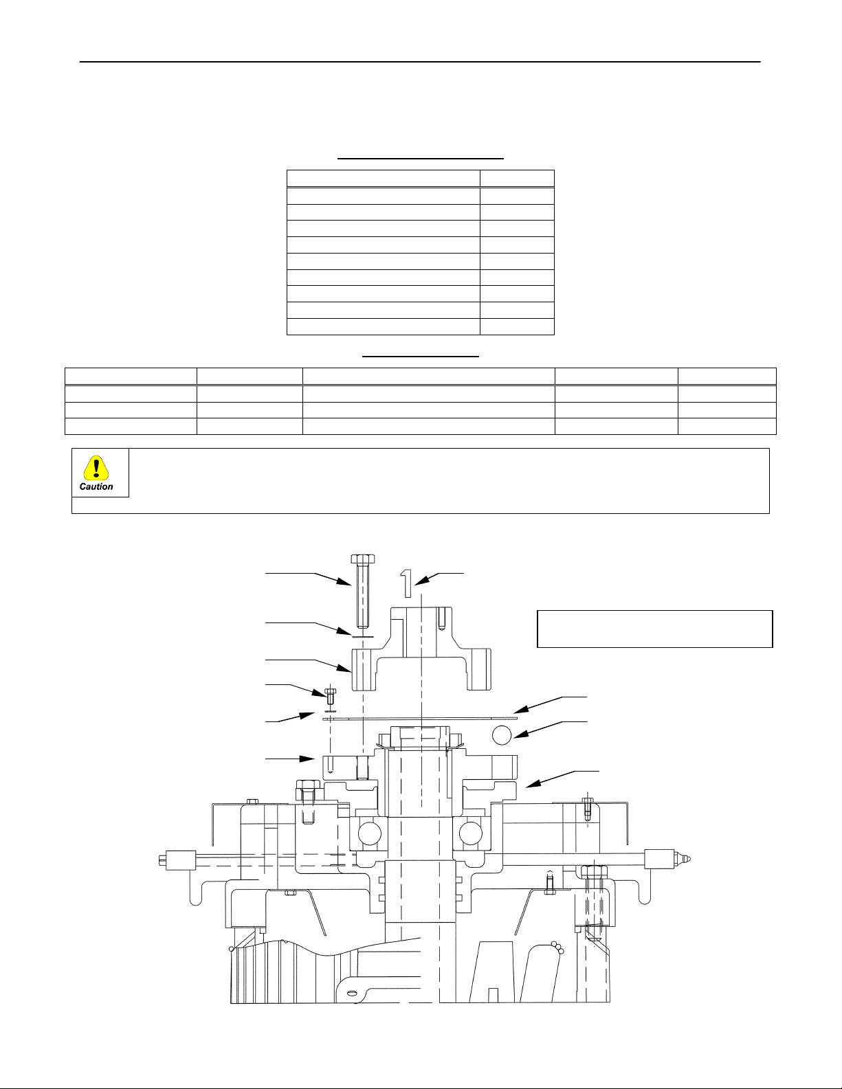
INSTRUCTION DIAGRAMS FOR MOUNTING 210 TO 280 FRAME
NON-REVERSE AND BOLTED COUPLINGS
(FOR 5KXXXXDTTXXXX MODELS)
Upper Half Coupling 1
Coupling Bolts 3
Coupling Lock Washers 3
Cover Plate 1
Cover Plate Bolts 5
Cover Plate Lock Washers 5
Steel Balls 10
Gib Key 1
Instructions 1
Part Name Frame Size Item Torque (Ft-Lbs) Torque (N-M)
Cover Plate Bolts 210 thru 280 1/4 - 20 UNC x 1/2 Bolt 8 11
Coupling Bolts 210 5/16 - 18 UNC x 1-3/4 Bolt 17 23
Coupling Bolts 250/280 3/8 - 16 UNC x 2-1/4 Bolt 30 41
It shall be the installer’s responsibility in all cases to ascertain these torque values are used
and maintained. This shall include those instances when the coupling comes mounted in the
motor. Failure to comply may cause the coupling bolts to break, with resultant, extensive
damage to the equipment.
NON-REVERSE COUPLING (NRC ASSEMBLY)
Coupling Bolts
Coupling Kit Packing List
Item Quantity
Bolt Torque Chart
Figure 1
Gib Key
Coupling Lock Washers
Upper Half-Coupling
Cover Plate Bolts
Cover Plate
Lower Half-
(Located on motor)
NOTE: Thoroughly clean coupling & all
related components prior to mounting on motor.
Cover Plate
Balls
Ratchet Plate
3
Page 4

GEI-M1026
Cover Plate Lock
Washers
pling
BOLTED COUPLING ASSEMBLY
Figure 2
Coupling Bolts
Gib Key
Coupling Lock Washers
Upper Half-Coupling
Cover Plate Bolts
NOTE: Thoroughly clean coupling & all
related components prior to mounting on motor.
Cover Plate
Lower Half-Cou
(Located on motor).
Ratchet Plate
Note: Steel balls are not used on bolted coupling assembly.
4
Page 5

GEI-M1026
INSTRUCTION DIAGRAMS FOR MOUNTING 320 TO 440 FRAME
NON-REVERSE AND BOLTED COUPLINGS
(FOR 5KXXXXDTTXXXX MODELS)
Upper Half Coupling 1
Coupling Bolts 6
Coupling Lock Washers 6
Cover Plate 1
Cover Plate Bolts 5
Cover Plate Lock Washers 5
Balls 10
Gib Key 1
Instructions 1
Part Name Frame Size Item Torque (Ft-Lbs) Torque (N-M)
Cover Plate Bolts 320/440 1/4 - 20 UNC x 5/8 Bolt 8 11
Coupling Bolts 320/360 1/2 - 13 UNC x 2-1/2 Bolt 75 102
Coupling Bolts 400/440 5/8 - 11 UNC x 3-1/2 Bolt 150 203
It shall be the installer’s responsibility in all cases to ascertain these torque values are used
and maintained. This shall include those instances when the coupling comes mounted in the
motor. Failure to comply may cause the coupling bolts to break, with resultant, extensive
damage to the equipment.
NON-REVERSE COUPLING (NRC) ASSEMBLY
Coupling Kit Packing List
Item Quantity
Bolt Torque Chart
Figure 3
NOTE: Thoroughly clean coupling & all
related components prior to mounting on motor.
5
Page 6

Note: Steel balls are not used on bolted coupling assembly.
NOTE: Thoroughly clean coupling & all
related components prior to mounting on motor.
GEI-M1026
BOLTED COUPLING ASSEMBLY
Figure 4
6
Page 7

GEI-M1026
Attn: Industrial Engineering
To:
g
Reader Comments
General Electric Company
GE Motors
Technical Publications Editor
1030 Swinney Ave, Bldg 26-2
Fort Wayne IN 46802-4332
Fax: 260-439-3881
(GE Internal DC: 8*380-3881)
We welcome comments and suggestions to make this publication more useful.
Your Name Today’s Date If needed, how can we contact you?
Your Company’s Name and Address Job Site Fax No.
GE Requisition No. Phone No.
Your Job Function / How You Use This Publication Publication No. E-Mail
General Rating
Contents
Organization
Technical Accuracy
Clarity
Completeness
Drawings / Figures
Tables
Referencing
Readability
Excellent Good Fair Poor Additional Comments
Specific Suggestions (Corrections, information that could be expanded on, and such.)
Page No.
Comments
Other Comments (What you like, what could be added, how to improve, and such.)
Overall Grade (Compared to publications from other manufacturers of similar products, how do you rate this publication?)
Superior Comparable Inferior Do not know Comment
Detach and fax or mail to the address noted above.
Publication Issue / Revision Date
Address
7
Page 8

GEI-M1026
……………………………………………….…………………Fold here and close with staple or tape………………………………….………………….
Place
Stamp
Here
GE MOTORS
INDUSTRIAL ENGINEERING TECHNICAL
PUBLICATIONS EDITOR
1030 SWINNEY AVE, BLDG 26-2
FORT WAYNE IN 46802-4332 USA
…………………………………………………..………….………………..Fold here first……………………………………………………………….
8
Page 9

Document Revision History
Rev # Date Author ISAAC # Description
0 03/27/06 Futter 06-0644 New manual for Ball NRC 320-440 frame motors.
GEI-M1026
9
 Loading...