

GE GEHTL-HPPR4-3NZ1, GEHTL-HPPR4-2NZ1, GEHTL-MPPB4-2NZ1, GEHTL-MPPR4-3NZ1, GEHTL-HPPB4-3NZ1 Installation Manual
...Page 1
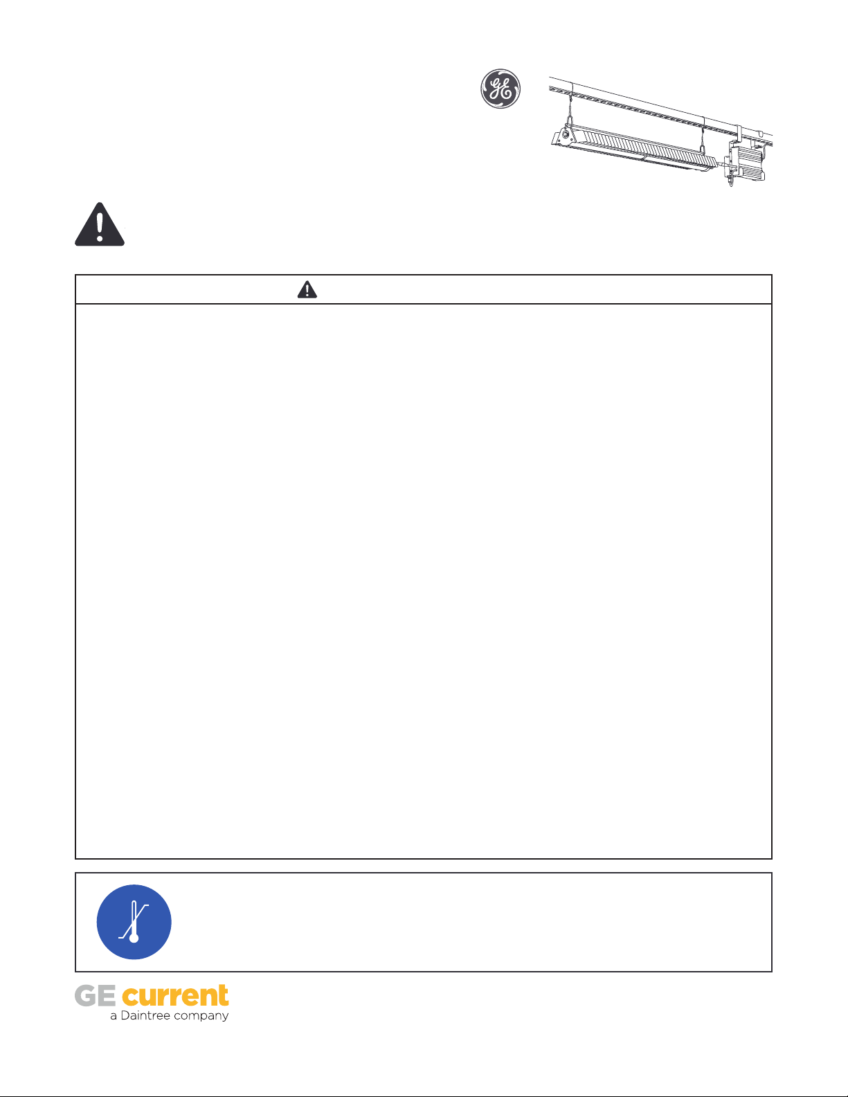
Arize ElementTM Top Light
Horticulture LED Lighting System
Installation Guide
BEFORE YOU BEGIN / AVANT DE COMMENCER
Read these instructions completely and carefully. Lisez attentivement ces instructions dans leur intégralité.
For Commercial or Industrial use only.
WARNING / AVERTISSEMENT
RISK OF ELECTRIC SHOCK
• Turn power o before installation, inspection, cleaning or removal.
And follow appropriate lock out/tag out safety procedure.
• Properly ground electrical enclosure.
• Follow all National Electric Codes (NEC) and local codes.
• This product must be installed in accordance with the applicable
installation code by a person familiar with the construction and
operation of the product and the hazards involved.
• The installation and associated structures are subject to
approval by the authority having jurisdiction.
• Use only with components identied in this document.
• Suitable for dry, damp, and wet locations; Do not immerse
any component.
• Wear suitable Personal Protective Equipment (PPE) during
installation/maintenance. Highly recommend safety glasses,
helmet and leather glove for luminaire mounting.
• Luminaire design for Greenhouse only.
RISK OF FIRE
• Minimum 3 inch distance from light module & driver to any
combustible material.
• Minimum 3 inch clearance between, light module & driver,
light module & light module, driver & driver.
• The light module shall be installed lens down with a
minimum 5 inch distance to anything below.
• All cables including connectors shall not be concealed or
extended through a wall, oor, ceiling, or other parts of the
building structure; located above a suspended ceiling or
dropped ceiling; permanently axed to the building structure.
• Cables shall be routed so that they are not subject to strain
and are protected from physical damage; visible over their
entire length; and used within their rated ampacity as
determined for the maximum temperature of the installed
environment specied in the instructions.
• For safe operation, and to maximize the longevity of the
luminaire; ensure that the light module and driver are
clean and free of dirt, dust, oil, or any other debris prior
to operation. Do not apply any kind of lm on the lens or
otherwise cover the driver or light engine in any way.
RISQUE DE CHOC ELECTRIQUE
• Coupez l’alimentation avant l’inspection, l’installation ou la
désinstallation.
• Reliez correctement le boîtier électrique à la mise à la terre.
• Suivre tous les codes électriques locaux applicables.
• Ce produit doit être installé selon le code d’installation
pertinent, par une personne qui connaît bien le produit et son
fonctionnement ainsi que les risques inhérents.
• L’installation et les structures associées sont soumises à
l’approbation des autorités compétentes.
• Utilisez uniquement avec les composants identiés dans ce document.
• Convient aux endroits secs, humides et mouillés. Ne doit pas être
immergé.
• Portez les équipements de protection individuelle appropriés
pendant l’installation et la maintenance. L’utilisation de
lunettes de sécurité, d’un casque et des gants de cuir pour le
montage du luminaire est fortement recommandée.
• Luminaire conçu pour serres seulement.
RISQUE D’INCENDIE
• Distance minimale de 3 pouces entre l’équipement d’éclairage
et toute matière combustible.
• Distance minimale de 3 pouces entre tout équipement
d’éclairage, module d’éclairage ou module d’alimentation.
• Le luminaire doit être installé avec l'objectif pointé vers le bas
avec une distance minimale de 5 pouces entre le luminaire et
tout objet.
• Les câbles et connecteurs ne doivent pas être dissimulés à
l’intérieur, ou passer à travers, d’un mur, d’un plancher, d’un
plafond ou de toute autre partie de la structure du bâtiment; ne
doivent pas être placés au-dessus d’un plafond suspendu; ne
doivent pas faire partie intégrante de la structure du bâtiment.
• Les câbles doivent être installés de façon à être protégés
contre l’étirement et tout autre bris physique; visibles sur
toute leur longueur; utilisés dans la limite de leur courant
admissible, déterminée pour les limites de température de
l’environnement spéciées dans le guide d’instruction.
• Pour une opération sécurisée et pour maximiser la longévité
du luminaire; S'assurer que le module d'éclairage et le module
d'alimentation sont propres et sans saleté, poussière, huile ou
autres débris avant l'opération. Ne pas appliquer tout type de
lm sur les lentilles et ne pas couvrir le module d'alimentation
ou le module d'éclairage de quelconque manière.
0°C
45°C
Suitable for operation in an ambient temperature
between 32°F (0°C) and 113°F (45°C).
A mechanical ventilation or cooling system is
required to maintain the temperature within the
growing space below 113°F (45°C) when the light
module is in operation.
1
Opération compatible avec un environnement à
temperature ambiante controlée entre 32°F (0°C)
et 113°F (45°C).
l’utilisation d’un système de contrôle de la
température sera nécessaire pour garder la serre sous
les 113°F (45°C) lorsque le luminaire est en function.
Page 2
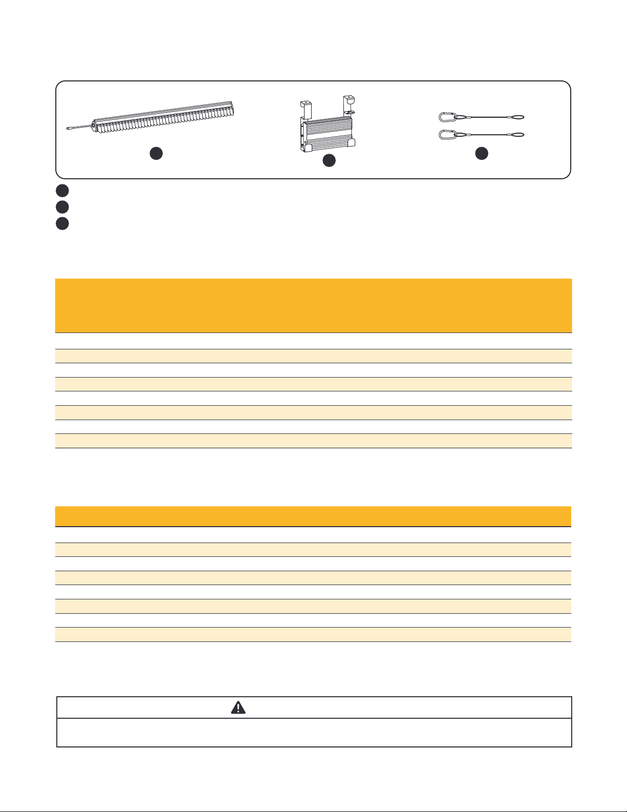
Base Kit Components Supplied
1
Top Light module
1
Driver with brackets
2
2 x 0.8 ft. support cables with carabiners
3
2
3
Specications
Driver Input Ratings
Typical Operating
Voltages at 50/60Hz
Description Detailed Description
GEHTL-HPPR4-2NZ1 Top light 4 ft purple reproductive, 641W 120/208/240/277 5.3/3.1/2.7/2.3 > 0.9
GEHTL-HPPB4-2NZ1 Top light 4 ft purple balanced, 641W 120/208/240/277 5.3/3.1/2.7/2.3 > 0.9
GEHTL-MPPR4-2NZ1 Top light 4 ft purple reproductive, 345W 120/208/240/277 2.9/1.7/1.4/1.2 > 0.9
GEHTL-MPPB4-2NZ1 Top light 4 ft purple balanced, 345W 120/208/240/277 2.9/1.7/1.4/1.2 > 0.9
GEHTL-HPPR4-3NZ1 Top light 4 ft purple reproductive, 627W 277/347/480 2.3/1.8/1.3 > 0.9
GEHTL-HPPB4-3NZ1 Top light 4 ft purple balanced, 627W 277/347/480 2.3/1.8/1.3 > 0.9
GEHTL-MPPR4-3NZ1 Top light 4 ft purple reproductive, 337W 277/347/480 1.2/1.0/0.7 > 0.9
GEHTL-MPPB4-3NZ1 Top light 4 ft purple balanced, 337W 277/347/480 1.2/1.0/0.7 > 0.9
(VAC)
Maximum
Current (A)
Power
Factor
Accessories
Description Detailed Description Components
GEHAK-NN-EB-N0 Light module 2’ UL remote mount kit 2 X 2 ft support cable + 3 ft UL DC cable + 2 Carabiners
GEHAK-NN-AC-N0 Light module 5’ UL remote mount kit 2 X 5 ft support cable + 6 ft UL DC cable+ 2 Carabiners
GEHAK-NN-BD-N0 Light module 10’ UL remote mount kit 2 X 10 ft support cable + 12 ft UL DC cable+ 2 Carabiners
GEHAK-DN-NN-N0 Driver 2¾” square member bracket 2 X 2¾” square brackets
GEHAK-BN-NN-N0 Driver 2¾” pipe member bracket 2 X 2¾” pipe brackets
GEHAK-AN-NN-N0 Driver 1 3/8” pipe member bracket 2 X 1 3/8” pipe brackets
GEHAK-NN-NE-N0 Driver universal wire mount kit 2 X 1ft driver support cables
*WAC 60 Wireless area controller 1 Router
*A single WAC60 supports up to 200 xtures. Customer needs to purchase WAC60 accordingly.
ATTENTION / ATTENTION
• Installation instructions and specications for
accessories can be found in the accessory package.
• Les instructions d’installation et spécications pour les accessoires
se retrouvent dans le kit d’accessoires.
2
Page 3

Sample Base Installation Diagram
Structural member
Structure
DRIVER
AC line
Plants Plants
Always wear safety gloves while handling light modules. Portez toujours des gants de protection lorsque vous manip-
Top Light Module
CAUTION / ATTENTION
DRIVER
ulez les luminaires.
Support
Cable
Unistrut
DRIVER
Installation
Hanging the Light Module
A
Structural member
A
B
Install the support cables
1
A) At rst end of light module, wrap non carabiner
end of support cable around structural member.
B) Pass carabiner through support cable loop to
create a noose.
Repeat with second support cable at other end of
Install the light module
2
A) Attach rst carabiner to the 1/4’’ round hole
on one side of the light module. Repeat on
other side of light module.
B) Ensure both carabiners are through the hole
and both gates are closed.
light module.
NOTE: Ensure greenhouse structures and members are rated for loads created by light modules and drivers.
Suitable min. 2 mm diameter suspension cable required to complete installation.
3
B
Page 4

Hanging the Driver
Driver output
Lift driver so that the structural member is
3
between the brackets.
NOTE: The base driver mounting kit is for a 1 5/8’’ square structural member. For other structural
members, see accessories or contact your account manager.
WARNING / AVERTISSMENT
RISK OF ELECTRICAL SHOCK: Turn power OFF before inspection, installation or removal.
RISQUE DE CHOC ELECTRIQUE: Coupez l’alimentation avant l’inspection, l’installation ou la désinstallation.
Driver Output
Electrical Connections
Male
Light module
Female
Driver
4
Rotate driver so that the brackets can engage with
the structural member. Lower driver into position.
Driver Input
Electrical Connections
AC line
Secure locknut
Connect light module to driver output
5
Mate male connector from module with female
connector from DC output of driver.
Secure blue lock nut by turning
counterclockwise until tight ensuring water
tight seal and good connection.
To driver input
Connect driver input to AC line
6
Connect the green wire to the incoming ground
conductor. Connect the black wire to Line 1 and
white wires to Neutral or Line 2 of the incoming
AC line.
4
Page 5

Connection Schematic
Use proper circuit
AC line
Driver Input Wire
Colors
Black = Line 1
White = Neutral or Line 2
Yellow/Green = Ground
WARNING /
protection level
AVERTISSEMENT
Ambient temperature surrounding each
driver must be lower than 113°F (45°C).
/ La température ambiante autour de
chaque module d’alimentation ne doit pas
excéder 113°F (45°C).
Zigbee Module
3-Phase Y
* * *
N
L3
L2
L1
Green
Driver
Optional 3’, 6’ or 12’ inter-connection cable
NOTE: Maximum cumulative length of inter-connection cable is 12 feet.
Driver Driver Driver Driver
REPEAT FOR ENTIRE CIRCUIT BALANCING OUT EACH PHASE
*White = Neutral or Line 2
Black
White
Green
Driver Driver
Black
White
Green
Black
White
Green
Black
3-Phase ∆
Green
Black
White
Light engine
White
Green
Black
White
Record IEEE Addresses
1
Record each Zigbee module’s IEEE address
(last 4 or 5 digits) with their physical locations.
This information will be useful during the
commissioning process for a marked-up copy
of the facility oor plan showing the identity
and location of each Zigbee module.
Initialize the ZigBee module
2 3
A) If not already powered up, energize the Zigbee
module by applying power to the driver input.
NOTE: If the Zigbee module has never join a network
(e.g. for new devices), go directly to section “Adding
the Zigbee modules to the Control Scope Manager.”
Otherwise, perform step 2B.
B) Press and hold the RESET button for a minimum
of 10 seconds to reset the unit.
IEEE Address
Reset Button
Adding the Zigbee modules to the Control
Scope Manager
For new devices, the Zigbee module must rst
be energized by applying power to the driver
input and joined to a network and congured
by following the instructions and online help
provided with the “Control Scope Manager”
(CSM) application.
5
Page 6

Save These Instructions
Use only in the manner intended by the manufacturer. If you have any questions, contact the manufacturer.
This device complies with part 15 of the FCC Rules. Operation is subject to the following two conditions: (1) This device may not cause harmful
interference, and (2) this device must accept any interference received, including interference that may cause undesired operation.
NOTE: This equipment has been tested and found to comply with the limits for a Class A digital device, pursuant to part 15 of the FCC Rules.
These limits are designed to provide reasonable protection against harmful interference when the equipment is operated in a commercial
environment. This equipment generates, uses, and can radiate radio frequency energy and, if not installed and used in accordance with the instruction manual, may cause harmful interference to radio communications. Operation of this equipment in a residential area is likely to cause
harmful interference in which case the user will be required to correct the interference at his own expense.
This Class [A] RFLD complies with the Canadian standard ICES-005. /CeDEFR de la classe [A] est conforme à la NMB-005 du Canada.
RISK GROUP 2 - CAUTION / ATTENTION - RAYONNEMENT LUMINEUX GROUPE 2
Possibly hazardous optical radiation emitted from this product. Do not stare at operating lamp. May be harmful to the eyes.
Le rayonnement lumineux émis par ce produit est potentiellement dangereux. Ne pas regarder la lumière émise
directement car elle pourrait occasionner des dommages aux yeux.
Save These Instructions
Use only in the manner intended by the manufacturer. If you have any questions, contact the manufacturer.
This device complies with part 15 of the FCC Rules. Operation is subject to the following two conditions: (1) This device may not cause harmful
interference, and (2) this device must accept any interference received, including interference that may cause undesired operation.
NOTE: This equipment has been tested and found to comply with the limits for a Class A digital device, pursuant to part 15 of the FCC Rules.
These limits are designed to provide reasonable protection against harmful interference when the equipment is operated in a commercial
environment. This equipment generates, uses, and can radiate radio frequency energy and, if not installed and used in accordance with the instruction manual, may cause harmful interference to radio communications. Operation of this equipment in a residential area is likely to cause
harmful interference in which case the user will be required to correct the interference at his own expense.
This Class [A] RFLD complies with the Canadian standard ICES-005. /CeDEFR de la classe [A] est conforme à la NMB-005 du Canada.
Electrical products must not be thrown out with domestic waste. They must be taken to
a communal collecting point for environmentally friendly disposal in accordance with
local regulations. Contact your local authorities or stockist for advice on recycling. The
packaging material is recyclable. Dispose of the packaging in an environmentally friendly
manner and make it available for the recyclable material collection-service.
For the latest install guides for your product go to:
https://products.currentbyge.com/horticulture/arize-element
arize.support@gecurrent.com
Email us:
Visit www.LED.com
Call us today! 1-888-MY-GE-LED
horticulture.info@gecurrent.com
GE and the GE Monogram are trademarks of the General Electric Company and are used under license. Information provided is subject to
change without notice. All values are design or typical values when measured under laboratory conditions, and GE makes no warranty or
guarantee, express or implied, that such performance will be obtained under end-use conditions. © 2019 GE Current, a Daintree company.
www.LED.com
HORT121 (Rev 12/17/19) A-1020191
 Loading...