

Page 1

http://waterheatertimer.org/Review-GE-Heat-Pump-water-heater.html
http://waterheatertimer.org/Which-is-best-hybird-heat-pump-water-heater.html
GE Water Heater
Introduction Nov 2009
http://waterheatertimer.org/Review-GE-Heat-Pump-water-heater.html
JJ 9/3/09
Page 2

Safety
IMPORTANT SAFETY NOTICE
The information in this presentation is intended for use by individuals
possessing adequate backgrounds of electrical, electronic, & mechanical
experience. Any attempt to repair a major appliance may result in
personal injury & property damage. The manufacturer or seller cannot be
responsible for the interpretation of this information, nor can it assume
any liability in connection with its use.
WARNING
To avoid personal injury, disconnect power before servicing this product.
If electrical power is required for diagnosis or test purposes, disconnect
the power immediately after performing the necessary checks.
RECONNECT ALL GROUNDING DEVICES
If grounding wires, screws, straps, clips, nuts, or washers used to complete
a path to ground are removed for service, they must be returned to their
original position & properly fastened.
2
Page 3

3
Page 4
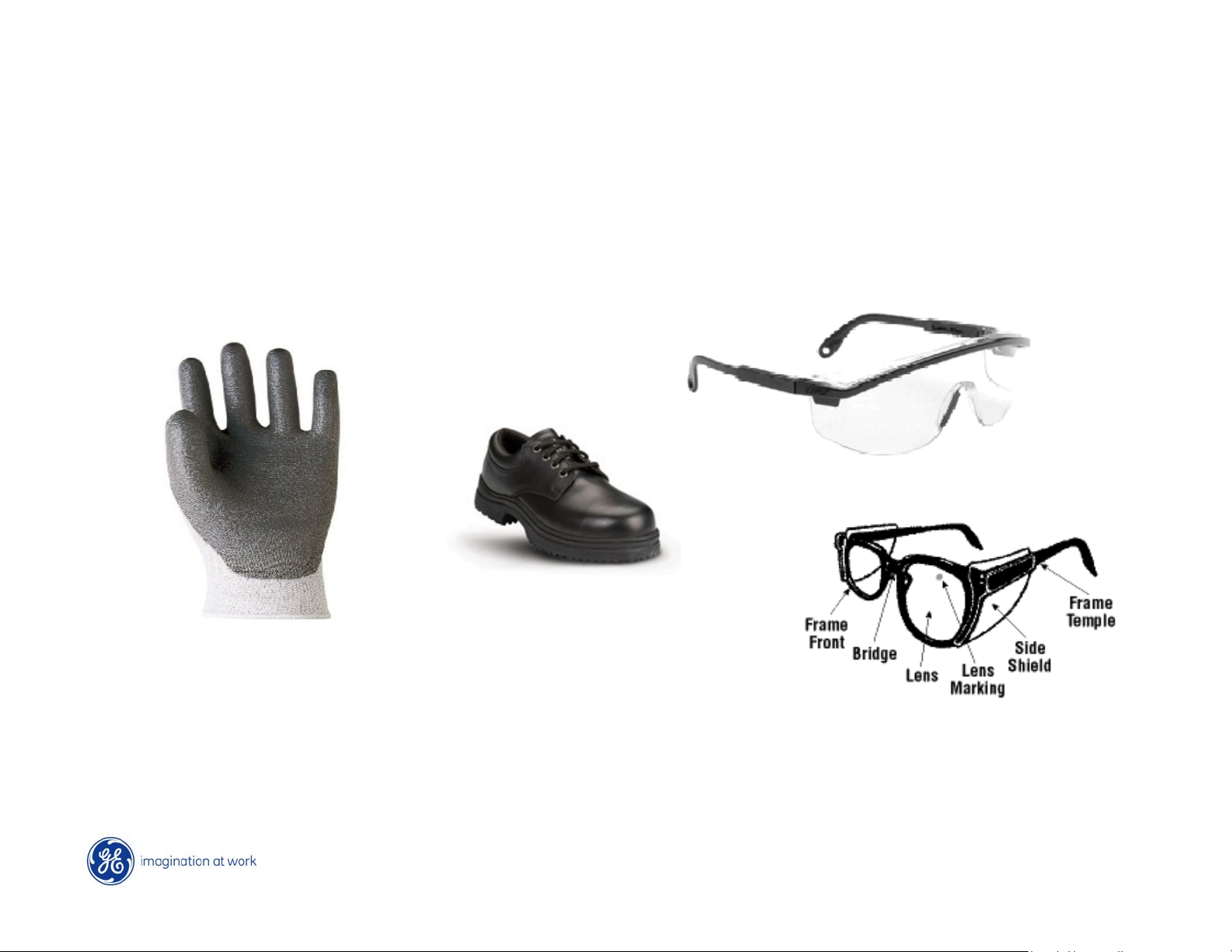
Personal Protection Equipment
GE Factory Service Employees are required to use safety glasses with side
shields, cut resistant (Dyneema®) gloves & steel toe shoes for all repairs.
Plano Safety Glasses
Dyneema® Cut
Resistant Glove
Steel Toe Shoes
Prescription Safety Glasses
Safety Glasses must be compliant with
ANSI Z87.1-2003
4
Page 5

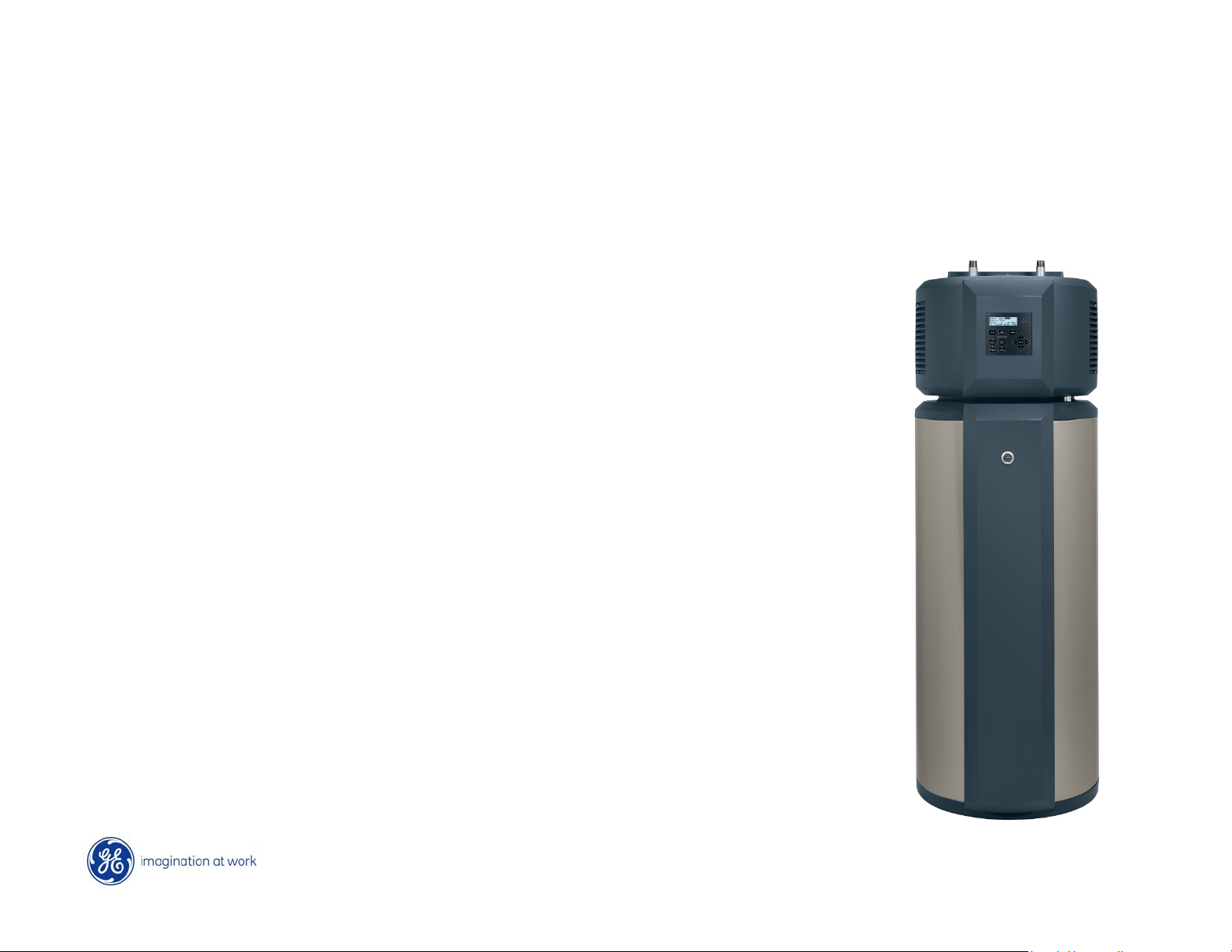
Features
Electric 50 Gallon Capacity
240 VAC 30 Amp circuit
LCD Electronic Control
Two 4500W Heating Elements
134a Sealed System (26.5 oz)
Temp Set Range 100°F – 140°F
Operating Pressure 20-120 psi
Product Weight – 200 lbs.
62”
22”
5
Page 6
GE is introducing a water heater to meet the new
2009 DOE ENERGY STAR
®
standards for heat-pump
water heaters. Energy Factor = 2.35 EF*
Designed to use approximately half
the energy and save $320 per year.*
Standard 50 gallon electric water
heater uses ~ 4880 kWh per year.
GE’s new water heater uses ~ 1856
kWh per year.
* Energy Star requirement is 2.0 EF or higher
* Based on 10.65 cents per kWh.
6
Page 7

Household Energy
7
Page 8

Exploded View
8
Page 9

Condenser
The condenser is
wrapped around
the tank, foamed
between the tank
and the outside
cabinet.
The condenser is
non-replaceable.
9
Page 10

Right Side View
10
Page 11

Rear View
11
Page 12

Left Side View
12
Page 13

Model/Serial Location
The model tag is located on the right front of the tank.
13
Page 14
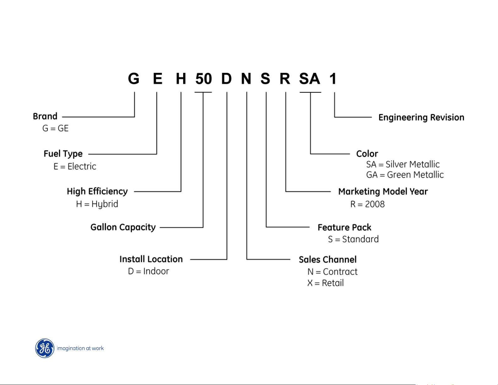
Nomenclature
Contract model has “High Demand” keypad on display.
All other features are the same for both models.
14
Page 15
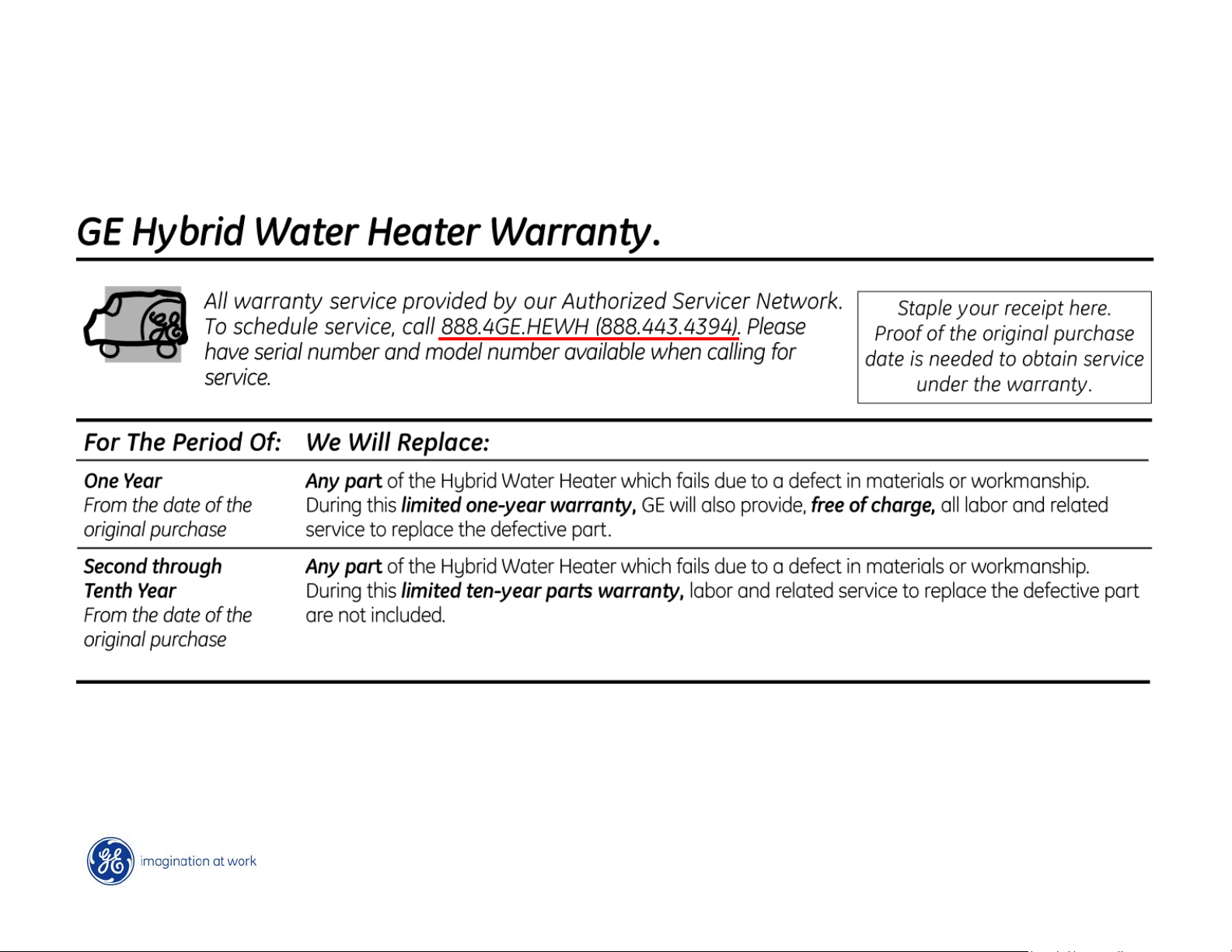
Warranty
15
Page 16

16
Page 17

Air Flow
17
Page 18

Installation - Location
5½” minimum 7” recommended
18
Page 19

Installation - Electric
240VAC
30 Amp Circuit
L1, L2, Ground
No neutral wire
19
Page 20

Junction Box
The junction box cover is held with 3 Phillips screws.
20
Page 21
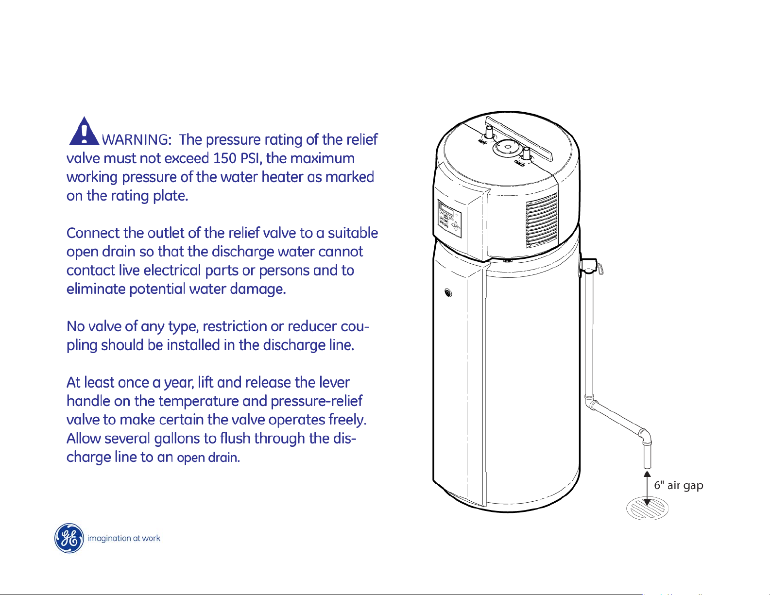
Installation – Pressure Relief Valve
21
Page 22
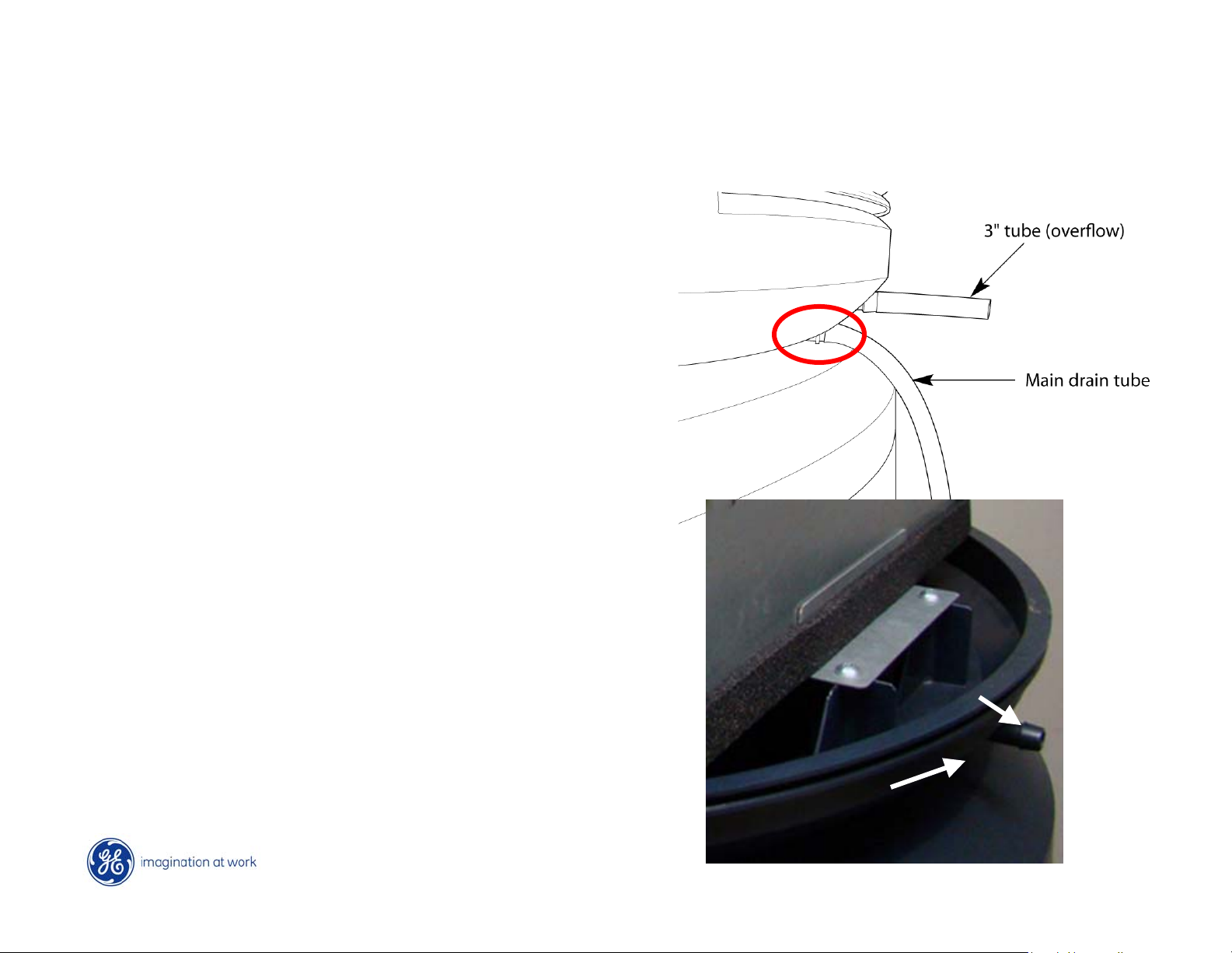
Installation – Condensate Drain
The 6’ main condensate drain
hose is pre-attached. The 3”
overflow tube is connected
during installation.
Easy to miss location of recessed
nozzle for main drain hose.
6’ main drain hose should be
directed towards suitable floor
drain.
Condensate water volume is
equivalent to a small
dehumidifier or 4000 BTU air
conditioner.
Overflow tube
nozzle
Main drain
nozzle
22
Page 23

Drain Hole Locations
Primary drain
Overflow drain
23
Page 24

Evaporator Seal
Overflow drain
Primary drain
Evaporator
Seal
Sealing lip
The seal below the evaporator forces all airflow to pass
through the filter and not under the bottom of the evaporator
24
Page 25

Control Display
25
Page 26

Modes of Operation
eHeat Mode – most energy efficient mode - uses only the sealed system. The
time required to heat water is longer, but should be adequate for normal
demand households. It will take 3-4 hours to initially heat a tank to 120F at
room temperature (4-6 hours in a colder room). Approximately one hour to
reheat from a 10 gallon flow.
Hybrid Mode – combines the energy efficiency of eHeat with the recovery
speed and power of the electric elements. The control automatically uses
efficient eHeat unless the majority of hot water is consumed.
Standard Electric Mode – uses the upper and lower heating elements to heat
the water. Heats water the fastest, but is the least energy efficient mode.
High Demand Mode – use this mode if your household has higher than
average water usage. The control will automatically use efficient eHeat if
water usage is normal, but when demand is higher, then standard electric
will be used.
26
Page 27
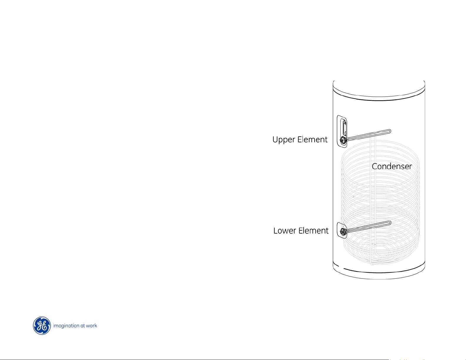
Three Heat Sources
The water heater has 3 heat sources:
1. Upper heating element
2. Lower heating element
3. Condenser
Only ONE heating source can be on
at a time.
The upper heating element has
priority. If a large temperature
increase is required, the upper
element is used (except in eHeat).
The lower element and condenser
are both considered “lower” heat
sources.
27
Page 28

Mini-Manual
The mini-manual is taped to the inside of the front cover.
Four Phillips screws (2 on each side) hold the covers together.
28
Page 29

Cover Installation
The covers have a lip that fits into a groove in the base. When
reinstalling, use the filter to hold the rear cover in place.
29
Page 30
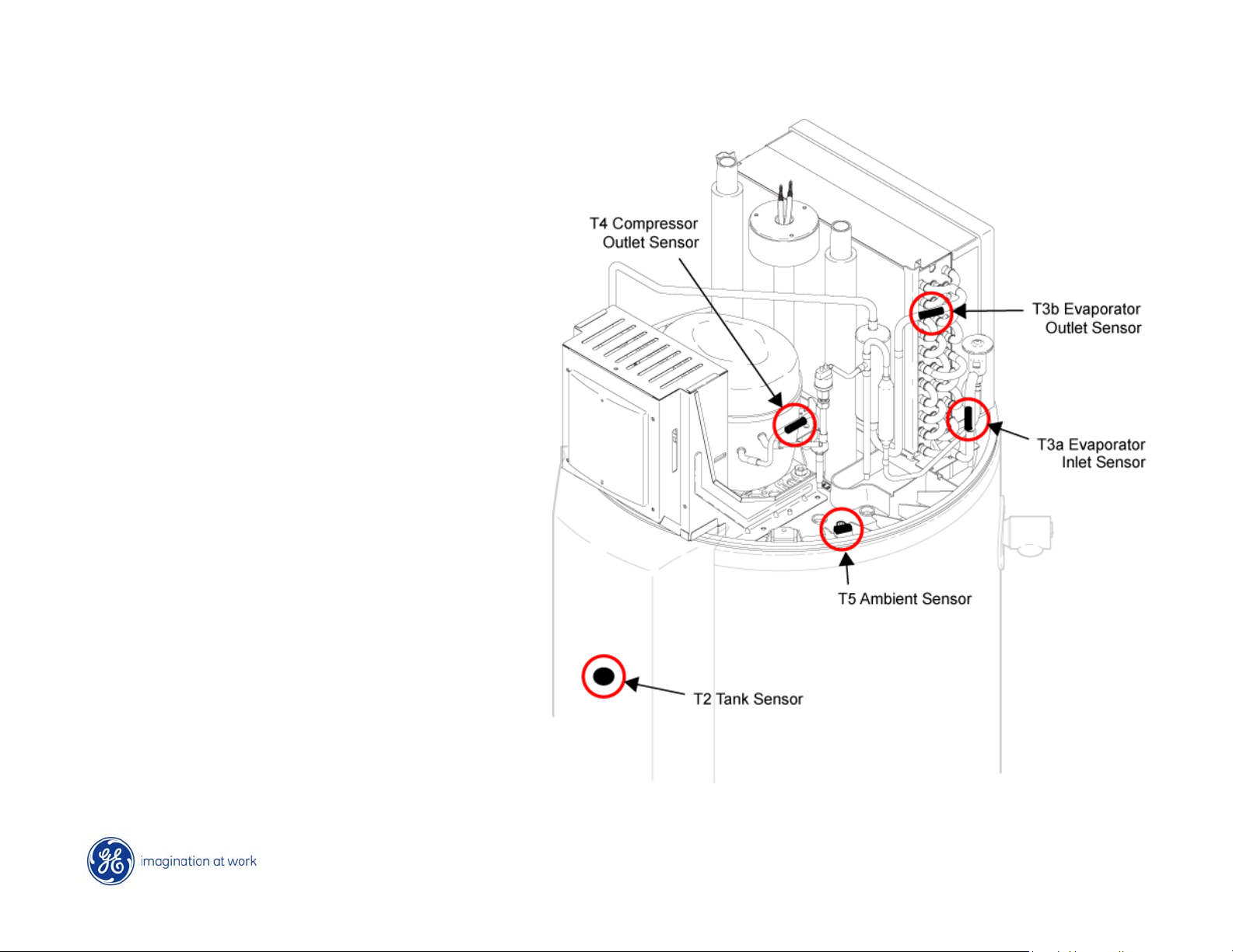
Sensors
The water heater has five
sensors.
Four of the sensors provide
the control with sealed
system information.
The T2 sensor provides info
on the tank temperature.
All sensors have a negative
coefficient resistance.
As the temperature
increases, the resistance
value decreases.
30
Page 31

T4
Compressor
Outlet
T3b
Evaporator
Outlet
T3a
Evaporator
T5
Ambient
Sensor
Inlet
31
Page 32

Sensor Chart
32
Page 33

T2 Sensor
Sensor Description Normal temperature
range
T2
Tank 30° F - 160° F 34K - 1.75K 10K
Resistance range in
ohms
Resistance at 77° F
33
Page 34

The T2 tank sensor provides the control with a
resistance value for determining tank
temperature.
It is the only feedback the control has for tank
temperature.
Just before the compressor starts, controls
checks to ensure T2 sensor temperature is
between 30°F and 160°F
The sensor is considered open if the voltage at
the board is greater than 4.88VDC and shorted
if less than .098VDC.
A T2 sensor fault is considered a critical failure
and will completely shut the system down,
CONTROL
BOARD
causing no hot water.
34
Page 35

T3a Sensor
Sensor Description Normal temperature
range
T3a
Evaporator
Inlet
15° F - 130° F 57K - 3K 10K
Resistance range in
ohms
Resistance at 77° F
35
Page 36

The T3a evaporator inlet sensor provides the control with
evaporator inlet temperature during sealed system operation.
The control checks the sensor to confirm:
1. Evaporator is frost free (above 32°F) at compressor startup.
2. Evaporator inlet is greater than 20°F after 30 minutes run time.
3. Temp difference between T3a and T3b is greater than 5°F after
30 minutes of run time
4. Using T5 ambient sensor, verifies T3a is at least 10°F less than
room temperature while sealed system is running.
5. The T3a, T3b and T5 sensors are all within 15°F of each other
before the compressor starts.
The sensor is considered open if the voltage at the board is
greater than 4.88VDC and shorted if less than .098VDC.
If any of the above tests fail, the control will stop the sealed
system and operate the water heater in electric mode.
36
Page 37

T3b Sensor
Sensor Description Normal temperature
range
T3b
Evaporator
outlet
15° F - 130° F 57K - 3K 10K
Resistance range in
ohms
Resistance at 77° F
37
Page 38

The T3b evaporator outlet sensor provides the control with
evaporator outlet temperature during sealed system operation.
The control checks the sensor to confirm:
1. Temp difference between T3a and T3b is greater than 5°F
after 30 minutes compressor run time.
2. The T3a, T3b and T5 sensors are all within 15°F of each other
before the compressor starts.
The sensor is considered open if the voltage at the board is
greater than 4.88VDC and shorted if less than .098VDC.
If any of the above tests fail, the control will stop the sealed
system and operate the water heater in electric mode.
38
Page 39

T4 Sensor
Sensor Description Normal temperature
range
T4
Compressor
outlet
30° F - 250° F 188K - 2K 55K
Resistance range in
ohms
Resistance at 77° F
39
Page 40

The T4 compressor outlet sensor provides the control with
compressor discharge temp during sealed system operation.
The control checks the sensor to confirm:
1. Outlet temp has risen at least 20°F during the 1st30 min
2. Outlet temp is greater than 120°F after the 1st30 min
3. Outlet temp never exceeds 240°F while operating
The sensor is considered open if the voltage at the board is
greater than 4.88VDC and shorted if less than .098VDC.
If any of the above tests fail, the control will stop the sealed
system and operate the water heater in electric mode.
40
Page 41

T5 Sensor
Sensor Description Normal temperature
range
T5
Ambient 15° F - 130° F 57K - 3K 10K
Resistance range in
ohms
Resistance at 77° F
41
Page 42

The T5 ambient temperature provides the control with a
reading of room temperature as the evaporator fans draw air
through the machine housing.
The control checks the sensor to confirm:
1. Ambient temperature is between 45°F and 120°F
2. The T3a, T3b and T5 sensors are all within 15°F of each
other before the compressor starts.
The sensor is considered open if the voltage at the board is
greater than 4.88VDC and shorted if less than .098VDC.
If any of the above tests fail, the control will stop the sealed
system and operate the water heater in electric mode.
42
Page 43

Initial Startup
The green LED above the POWER pad must be lit for the
water heater to operate. Press the POWER pad to start
the unit. The display blanks after 5 minutes of inactivity.
43
Page 44

Upon power-up, default settings are Hybrid Mode
and a water temperature of 120°F
44
Page 45

Dry Tank Test
Upon initial installation, or anytime the power LED is OFF and
power is then disconnected, the water heater will run a dry
tank test before starting the selected heating mode.
The control will run the evaporator fans for 90 seconds and
then start the sealed system. The control will run the sealed
system for 5 minutes and monitor the tank temperature from
the T2 sensor. If the control sees a temperature rise of more
than 1.5 degrees, it assumes the tank is empty, shuts off heat
and displays a warning to fill the tank (a full tank would absorb
the heat and the temperature increase would take longer).
NOTE: If power is lost while the power LED is ON, when
power is restored, the control will resume whatever
heating mode had been operating prior to power loss.
45
Page 46

Sealed System Startup
Room temperature
between 45°F - 120°F
and evaporator
above 32°F?
The upper limit avoids a
compressor overheat, the
lower limit prevents liquid
refrigerant from entering the
compressor as well as
inefficiency due to the lack of
heat in the air.
Start sealed system
46
Page 47

Temperature Chart
Rate Of Decay
The speed at which the temperature drops determines
when and what heat source the control uses to recover.
47
Page 48

eHeat Mode
Water temperature 5°F
less than set point or
1°F less if water has
been used?
Start sealed system
Note: Evaporator fans run for 10 minutes after compressor cycles off
48
Page 49

Standard Electric Mode
49
Page 50

Water temperature 5°F less than set point?
Use Lower Element
Water temperature 1°F less than set point and water has
been used?
Use Lower Element
Water temperature 25°F less than set point?
Use Upper Element until 7°F less than set point, then:
Use Lower Element
50
Page 51

Hybrid Mode
51
Page 52

Water temperature 5°F less than set point?
Use Sealed System
Water temperature 1°F less than set point.
Small amount of water has been used (less than 10 gallons)?
Use Sealed System
Large amount of water has been used (20-30 gallons)?
Use Lower Element
Water temperature 30°F less than set point?
Use Upper Element until 7°F less than set point, then:
Lower Element if large water flow during upper element on time
Sealed System is no water flow during upper element on time
52
Page 53

High Demand Mode
53
Page 54

Water temperature 5°F less than set point?
Use Sealed System
Water temperature 1°F less than set point.
Small amount of water has been used (less than 10 gallons)?
Use Sealed System
Medium amount of water has been used (10-20 gallons)?
Use Lower Element
Water temperature 20°F less than set point?
Use Upper Element until 7°F less than set point, then:
Lower Element if medium flow during upper element on time
Sealed System is no water flow during upper element on time
54
Page 55

Control Boards
Membrane
ribbon
Anti-static
ground
55
Page 56

LCD
Main Control
Board
Power Supply
Board
Housing removed
56
Page 57

Membrane
ribbon
Limited access with the control boards in place
57
Page 58

Removing 4 Phillips screws (2 on each side) and a
ground screw allows the control housing to tilt forward.
58
Page 59

Accessible for service
59
Page 60

RY4
Compressor
RY3 Lower
Power supply board
12 VDC from
power board
Element
RY2 Upper
Element
RY1 Double
Line Break
Current
sensor
Evaporator
fans
Sensors
Membrane
connector
Demand
Main control board
response
60
Page 61

Current Sensor
The current sensor enables
the control to determine
when the compressor, upper
element and lower element
are operating.
The control checks the
component 5 seconds after
powered and every 10
minutes thereafter.
Compressor > 1.5 amps
Heating Elements > 10 amps
61
Page 62

Evaporator Fans
Two 12VDC evaporator fans operate simultaneously to draw
air through the evaporator and exhaust it out the rear cover.
The fans run at the same RPM. If either fan fails, a fault is
recorded and the unit switches to electric mode.
62
Page 63

The control varies the fan speed using pulse-width modulation
to maintain the desired evaporator temperature based on
ambient temperature. When the room temperature is low, the
fans run at a higher speed to move additional air across the
evaporator. The average fan speed based on average room
temperature is approximately 3000 RPM, which is ~56 dBA.
The fans run for 90 seconds
before the compressor
starts and for 10 minutes
after the compressor cycles
off.
NOTE: Unless the unit switches to
electric mode, which turns the fans
off immediately.
63
Page 64

Front Cover
The front cover has two molded
posts at the top which fit into
holes at the top of the tank. A
magnetic catch at the bottom
holds the cover in place.
To remove, pull the cover out at
the bottom and lift approximately
an inch to clear the posts at the
top.
Removing the cover provides
access to the heating element
covers and the drain valve.
64
Page 65

Drain Valve
The drain valve at the front
bottom of the tank has a
standard garden hose fitting.
After attaching an appropriate
length hose, use a flat-bladed
screwdriver to open the valve.
The Use & Care manual
recommends the consumer
drain several quarts of water
from the tank every month to
prevent sediment buildup in
the bottom of the tank.
65
Page 66

If flushing the tank, disconnect power but leave the water
supply turned on. The flow of cold water into the tank
helps to stir the sediment at the bottom and force it out
the drain hose.
If replacing a heating element or pressure relief valve,
disconnect power, turn off the water supply and open a
faucet somewhere in the home. Drain the tank to the
appropriate level and make the necessary repair.
NOTE: When flushing or draining the tank, always allow
water to flow for several minutes at a tub faucet after the
repair. This will help to purge any air from the system
and remove any stirred-up sediment which could clog
other home faucets that contain screens.
66
Page 67

Heating Element Covers
Each cover is held by two T15H Torx security screws.
The Styrofoam insulation under the cover pulls straight out.
67
Page 68

Heating Elements
The thread pattern is the
standard counter-clockwise
to loosen, clockwise to
tighten.
The torque on the heating
element is approximately
25 foot lbs.
The heating element
threads will bottom just
after the heating element
gasket seats to the tank.
68
Page 69

A 1 ½” heating element
wrench is available under the
part number WX05X10103.
The wrench is capable of
using a ½” drive ratchet, a
large Phillips screwdriver or a
3/8” pry bar handle.
Lower element
69
Page 70

The upper and lower heating elements
are identical.
Each heating element is rated at 4500
watts at 240V.
The current draw is approximately 18.75
amps and the resistance is 12.8 ohms.
The control will record a heating element
fault if the current is less than 10 amps
when the element relay on the board is
energized.
The overall length of the heating element
is 14 ½ inches.
70
Page 71

Thermal Cutouts (TCO)
The thermal cutouts provide
additional safety from tank
overheating.
TCO #2 trips at 170°F and
breaks both L1 and L2.
TCO #1 trips at 160°F and
breaks the L1 circuit.
If either TCO opens, all heating
sources (upper element, lower
element and compressor) are
disabled. Both thermal cutouts
require a manual reset.
71
Page 72

To replace a thermal cutout,
remove the two Phillips
screws holding the bracket
and dielectric barrier over
the thermal cutouts.
If a thermal cutout has
opened, suspect a shorted
relay on the control board,
T2 (tank sensor) problem or
a failure of the cutout itself.
72
Page 73

During production,
thermal paste is used
under the cutout to
provide additional
conductivity between the
tank and the TCO.
It is not necessary to
apply additional paste if
the cutout needs to be
replaced.
Never just reset a
thermal cutout without
determining the reason
for the circuit opening.
73
Page 74

Discharge Pressure Switch
The discharge pressure switch is an
additional safety device for the sealed
system, backing up the T4 compressor
outlet sensor.
The normally closed switch is designed
to open the compressor circuit if the
discharge pressure exceeds 400 psi.
It will reset once the pressure drops
below 300 psi.
If the switch opens within 1-2 minutes
of compressor start up, check for a
sealed system restriction.
74
Page 75

The lower 9/16” nut is brazed to
the copper tube. Hold it
stationary while turning the
upper 9/16” nut in a counter-
clockwise direction to remove
the switch.
NOTE: There are two reasons
for using care when removing
the switch:
1. The wires twist as the switch
is unscrewed, so care is needed
to prevent damaging the wires.
75
Page 76

2. The switch uses a
built-in plunger to
engage a Schrader valve
in the lower assembly.
Once loose, it must be
removed quickly to
avoid leaking excessive
refrigerant.
76
Page 77

Recovering Refrigerant
The valve assembly can be
used to recover refrigerant
from the system.
When reinstalling
the switch, pretwist the wires
several turns in a
counter-clockwise
direction so the
wires are straight
when the switch is
tightened in place.
77
Page 78

Refrigerant Charging
To charge the sealed system,
install a valve on the low side
of the compressor, where the
process stub was located.
Charge the system
with 26.5 ounces of
R134a refrigerant.
78
Page 79

Thermal Expansion Valve (TXV)
79
Page 80

Valve Design
The TXV consists of a valve, spring and diaphragm attached
to a capillary bulb filled with a small amount of a blended
refrigerant (primarily R134a). The TXV is designed to
provide a fixed superheat of approximately 10°F.
80
Page 81

Superheat
The TXV meters the flow of liquid refrigerant entering the
evaporator at a rate that matches the amount of refrigerant
being boiled off in the evaporator (gas). The valve maintains
the proper “superheat” of approximately 10°F (T3b - T3a).
Superheat is the temperature of a gas above the boiling point
for that liquid. If a refrigerant liquid boils at a temperature of
40°F in a cooling coil, and then the refrigerant gas increases in
temperature, superheat has been added. If this refrigerant
changed from a liquid to a gas or vapor at 40°F and then the
refrigerant vapor increased in temperature to 50°F, it has
been superheated by 10°F.
81
Page 82

The TXV has several forces acting upon it. The pressure of the
refrigerant entering the evaporator, the spring pressure in the
valve and the pressure on the diaphragm from the bulb. As
the temperature of the bulb at the evaporator outlet increases,
the pressure of the refrigerant in the bulb forces the valve
open. Although the TXV is designed to maintain a superheat of
approximately 10°F (T3b – T3a), a range of 7°F - 18°F is
considered normal.
The valve operation can also be monitored by T3a temperature
based on room temperature (T5 sensor).
T5 T3a
60°F 47°F +/- 3°F
70°F 48°F +/- 3°F
90°F 65°F +/- 3°F
82
Page 83

Thermal Seal
Capillary should be directed upwards
Mastic wrap Mastic removed
The bulb is clamped to the outlet of the evaporator, above the
T3b sensor. The bulb and sensor are securely wrapped with
mastic to provide an accurate transfer of tube temperature.
83
Page 84

TXV Bulb Position
BULB
TUBE
The position of the bulb on the copper tubing is critical.
Ensure the bulb is attached on the top side of the tube,
between the 10 o’clock and 2 o’clock position.
84
Page 85

Tube Position
Condensation on certain areas of the expansion valve is normal.
Make certain the valve or tubing is not against the outer cover
where water could leak down the outside of the water heater.
85
Page 86

TXV Replacement Part
The valve body is heat sensitive. It is recommended to
use a heat absorbing paste such as WX5X8927 or
equivalent should the TXV require replacement.
86
Page 87

Anode Rod
The anode rod is magnesium wrapped around
a steel core wire to protect against corrosion.
When the tank is filled with water, an
electrolytic process begins, where over time,
the sacrificial magnesium anode is consumed.
All metals fall somewhere on the galvanic
scale of reactivity. When two are placed
together in water, the "nobler“, or less reactive
one, will remain intact while the more reactive
one corrodes.
In the water heater, the magnesium corrodes
over time while the steel tank remains intact.
87
Page 88

The anode rod is 42” long with a 1 1/16” hex head. The torque on
the nut is 90 ft lbs. The anode rod should last the life of the water
heater unless unusual water conditions exist.
88
Page 89

Dip Tube
The 43” long, 5/8” diameter
stainless steel dip tube,
located beneath the cold
water inlet pipe, directs
cold water to the bottom
of the tank.
Hot water at the top of the
tank is used first when
water flows from the tank.
The cold water inlet pipe
must be disconnected to
access the dip tube.
89
Page 90

Demand Response Module
Module
6 ft.
interconnect
cable
The Demand Response module is an optional appliance used to
communicate with the local utility company (if available).
90
Page 91

Demand Response Modes
Mode 1 - Low
Normal mode of operation as prescribed by consumer.
Mode 2 - Medium
Unit switches to eHeat™ Mode. Water temperature set
point remains at current user setting.
Mode 3 - High
Unit continues to operate in eHeat™ Mode. Water
temperature setpoint automatically adjusted down to
110F if consumer set point is above 110F.
Mode 4 – Critical (Peak)
Unit continues to operate in eHeat™ Mode. Water
temperature set point automatically adjusted down to
100F if consumer set point is above 100F.
91
Page 92

Diagnostic Mode
#2
#1
Press the ENERGY MENU pad, then the ENTER pad
92
Page 93

Using the down arrow, scroll to the second screen
93
Page 94

Press the ENTER pad to enter the diagnostics menu
94
Page 95

Component Status
Scroll to a selection and press the ENTER pad
95
Page 96

Several selections within the diagnostics menu
require an access code
96
Page 97

Access Code
#1
#3
The access code is FILTER, LOCK and VACATION pads
pressed sequentially within 3 seconds of each other
#2
97
Page 98

Use the down arrow to scroll through the selections
98
Page 99

T2 Sensor
Displays current temperature, sensor range and
current resistance value in real time
99
Page 100

T3a Sensor
Displays current temperature, sensor range and
current resistance value in real time
100
 Loading...