

Page 1

g
GEH–6505A
POWER LEADER™
Ethernet Gateway
User’s Guide
Page 2

GEH–6505
WARNINGS, CAUTIONS, AND NOTES
AS USED IN THIS PUBLICATION
WARNINGS
CAUTIONS
NOTES
Warning notices are used in this publication to emphasize that hazardous voltages, currents, or other conditions that could cause personal injury exist in this equipment or
may be associated with its use.
Warning notices are also used for situations in which inattention or lack of equipment
knowledge could cause either personal injury or damage to equipment.
Caution notices are used for situations in which equipment might be damaged if care
is not taken.
Notes call attention to information that is especially significant to understanding and
operating the equipment.
This document is based on information available at the time of its publication. While
efforts have been made to ensure accuracy, the information contained herein does not
cover all details or variations in hardware and software, nor does it provide for every
possible contingency in connection with installation, operation, and maintenance.
Features may be described herein that are not present in all hardware and software
systems. GE Electrical Distribution & Control assumes no obligation of notice to
holders of this document with respect to changes subsequently made.
GE Electrical Distribution & Control makes no representation or warranty, expressed,
implied, or statutory, with respect to, and assumes no responsibility for the accuracy,
completeness, sufficiency, or usefulness of the information contained herein. No
warrantees of merchantability or fitness for purpose shall apply.
REFERENCES
POWER LEADER™ is a registered trademark of GE Company.
Modbus RTU is a registered trademark of AEG Schneider Automation.
For details of the Modbus RTU protocol, refer to PI-MBUS-300 Rev. E from
Modicon/AEG Schneider Automation.
For details of RS485 communications, refer to the EIA-485 standard.
©Copyright 1996 GE Company
All Rights Reserved
Page 3

POWER LEADER™ Ethernet Gateway
Table of Contents
Chapter 1 – Introduction ...........................................................................................1
1–1 Overview .................................................................................................................................. 1
1–2 Physical Description ............................................................................................................... 2
1-3 Operational Description.......................................................................................................... 3
Message Format................................................................................................................. 3
Gateway/Host Interface.................................................................................................... 3
1–4 Specifications .......................................................................................................................... 4
1–5 Environmental Requirements................................................................................................ 4
1–6 Terminology............................................................................................................................ 4
Chapter 2 – Installation .............................................................................................5
2–1 Mounting................................................................................................................................. 5
2–2 Control Power Connections................................................................................................... 5
2–3 Ethernet Connection.............................................................................................................. 5
2–4 Modbus Connection............................................................................................................... 6
2–5 Diagnostic Connection........................................................................................................... 6
2–6 Wiring Rules for Modbus Networks....................................................................................... 6
2–7 Modbus Equivalent Addresses............................................................................................... 7
Chapter 3 – Configuration.........................................................................................8
3–1 Configuration Procedure....................................................................................................... 8
3–2 Ethernet Gateway IP Address................................................................................................. 9
3–3 Baud Rate Specification......................................................................................................... 9
3–4 Message Monitoring ............................................................................................................. 10
3–5 Ethernet Driver ..................................................................................................................... 10
3–6 Gateway Diagnostics ............................................................................................................. 11
Display Socket, IP Address and Subnet Mask................................................................ 11
RS485 Loop-back Test..................................................................................................... 11
Ethernet Test ................................................................................................................... 11
Exit Diagnostics Program............................................................................................... 11
Network Test – FACTORY USE ONLY .......................................................................... 12
3–7 Advanced Options – Technical Support Personnel ONLY ............................................... 12
Updating the Gateway Software ..................................................................................... 12
Chapter 4 – Operation .............................................................................................13
Chapter 5 – Diagnostic Messages and Errors .......................................................14
5–1 Monitor Mode....................................................................................................................... 14
5–2 Processing Error Messages ................................................................................................... 14
Chapter 6 – Troubleshooting Guide .......................................................................15
RS485 Port Configuration Worksheets..................................................................16
i
Page 4

POWER LEADER™ Ethernet Gateway
Table of Contents
List of Figures
Figure 1. POWER LEADER Ethernet Gateway. ............................................................................................ 1
Figure 2. Typical use of Ethernet Gateway. ...................................................................................................2
Figure 3. Front view of Ethernet Gateway, showing dimensions. ................................................................ 2
Figure 4. Rear view of the Ethernet Gateway, showing Ethernet, RS485 and RS232 ports........................ 2
Figure 5. Ethernet headers on Modbus messages......................................................................................... 3
Figure 6. Mounting hole patter for Ethernet Gateway. ................................................................................ 5
Figure 7. Connecting control power to the Ethernet Gateway..................................................................... 5
Figure 8. Making the Ethernet connection to the Gateway. ........................................................................ 5
Figure 9. Connecting an RS485 network to the Ethernet Gateway.............................................................. 6
Figure 10. Termination of the RS485 network at the last Modbus device.................................................. 6
Figure 11. Connecting a dumb terminal to the RS232 port......................................................................... 6
Figure 12. Terminal communications settings. ............................................................................................8
Figure 13. Ethernet Gateway configuration menu........................................................................................ 8
Figure 14. Gateway diagnostics menu.......................................................................................................... 11
List of Tables
1. Examples of Modbus RTU compatible devices. .......................................................................................1
2. POWER LEADER Ethernet Gateway specifications. ................................................................................ 4
3. POWER LEADER Ethernet Gateway environmental requirements........................................................ 4
4. POWER LEADER commnet devices supported by the Modbus Concentrator...................................... 7
5. RS485 Port Settings.................................................................................................................................... 10
6. Diagnostic messages key............................................................................................................................ 14
7. Error message key...................................................................................................................................... 14
ii
Page 5
POWER LEADER™ Ethernet Gateway
Chapter 1 – Introduction
Chapter 1 – Introduction
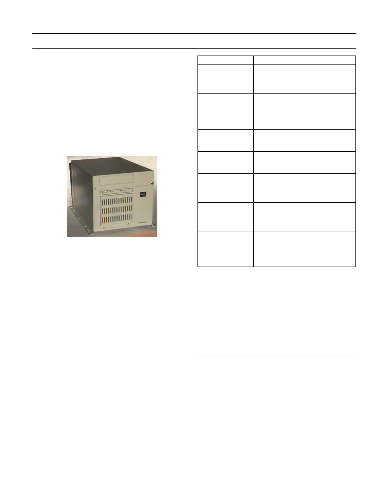
1–1 Overview
The GE POWER LEADER™ Ethernet Gateway
(catalog number PLENETG01), shown in Figure 1,
is a microprocessor-based device that connects one
to four RS485-based Modbus Remote Terminal Unit
(RTU) networks to an industry-standard, highspeed Ethernet network. Up to 31 Modbus RTU
devices can be connected to each of the Modbus
RTU networks.
Figure 1. POWER LEADER Ethernet Gateway.
The Ethernet Gateway works with GE’s Power
Management Control System (PMCS), a
comprehensive power management software
platform that acts as the ‘host’ to RS485 networks
attached to the Ethernet Gateway. A special part of
the PMCS called the Dynamic Data Exchange
(DDE) server is a database that records the
addresses and configurations of all attached
devices. The Ethernet Gateway serves as a passthrough device, interpreting the addressing
information and routing queries from the host to
the Modbus RTU networks and passing answers to
those queries from the attached devices back to the
host.
The Ethernet Gateway strictly conforms to the
Modbus RTU protocol, providing the capability to
tie the supported Modbus RTU devices into an
Ethernet network. Table 1 contains a partial list of
devices that are compatible with the Ethernet
Gateway and conform to the Modbus RTU
standard.
Device Description
EPM 3710 Full-function, three-phase electronic
meter with optional pulse initiation,
waveform capture, data logging, and
protective relay outputs.
EPM 3720 Full-function, three-phase electronic
meter with optional pulse initiation,
waveform capture, data logging,
protective relay outputs, and harmonic
distortion measurements.
Multilin 269 Plus
Motor Management
Relay
Multilin 565 Feeder
Management Relay
Fanuc 90/30 PLC Programmable logic controller (PLC)
Fanuc 90/70 PLC Programmable logic controller with
Modbus
Concentrator
Table 1. Examples of Modbus RTU compatible devices.
Protection for medium-voltage
industrial motors and associated
mechanical systems.
Complete time-overcurrent phase and
ground protection by monitoring feeder
phase current and ground current.
for applications from simple relay
replacement to midrange process
control.
multiple processors and programming
capabilities for large, high-speed
applications.
Maps addresses of up to 32 attached
POWER LEADER communications
network (commnet) devices to
equivalent Modbus addresses for use
with the Ethernet Gateway.
NOTE: PMCS is certified for use with power
management components manufactured 5/13/96
or later. If your system interfaces to: 1) any trip
units, meters, or relays manufactured prior to
5/13/96, or 2) any Spectra RMS™ Circuit Breakers
with MicroVersaTrip PM™ Trip Units, please
contact the POWER LEADER Customer Support
Center at 1-800-843-3742.
As mentioned in Table 1, the Modbus Concentrator
allows integration of POWER LEADER commnet
devices with Modbus RTU-compatible networks for
use with the Ethernet Gateway. See Section 3–5 for
more details on the integration of commnet devices
into Modbus networks.
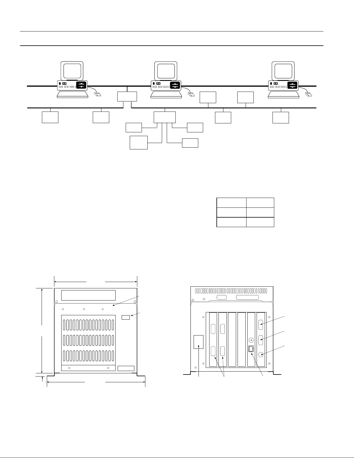
Figure 2 illustrates a typical Modbus RTU network
connected to a high-speed Ethernet through an
Ethernet Gateway.
1
Page 6
POWER LEADER™ Ethernet Gateway
Chapter 1 – Introduction
Ethernet
E PM
37 2 0
Host
PMCS
E PM
37 10
Ethernet
Gateway
PL EPM
RS485 Modbus RT URS485 Modbus RTU
PO WE R
LEADE R
Met er
Other
Mod bus
Concentr ator
Figure 2. Typical use of Ethernet Gateway.
1–2 Physical Description
Figure 3 is an outline drawing showing the
dimensions of the Ethernet Gateway. Figure 4 is a
rear view of the Gateway showing its control power,
Ethernet, RS485 and RS232 connections.
The following ports and connections are provided
on the Gateway:
• A pair of Ethernet ports provides input and output
connections to the either a 10BaseT or a 10Base2
Ethernet network.
• Four RS485 ports support up to four Modbus RTU
networks, labeled Network 1 to Network 4, with as
P C
Spectra
E CM
MVT - PM
Tri p Unit
PL C
90 /30
Mult i l in
26 9+
commnet devi ces
Mult il in
56 5
Other
P C
PLC
90 /70
many as 31 Modbus devices each and up to 247
Modbus addresses each. RS485 ports are DB-9 (9-pin
D shell) connectors with the following pin
assignments:
Data - Pin 1
Data + Pin 2
Ground Pin 5
• One RS232 port (also DB-9 style) allows connection
of a dumb terminal for configuration and
troubleshooting of the Ethernet Gateway.
• A standard PC-style power connector for AC control
power input.
6.7 in.
170.0 mm
0.32 in.
8.0 mm
7.5 in.
166.0 mm
Power
HDD Reset
7.32 in.
196.0 mm
Figure 3. Front view with dimensions.
Status
LEDs
Power
on/off
switch
Length:
15.5 in.
393.0 mm
2
Control power
connection
1
3
4
2
Four
RS485
ports
10Base2 and
10BaseT
Ethernet ports
Figure 4. Rear view showing ports.
Com 1
RS232 port for
dumb terminal
Com 2
RS232 port
not used
keyboard port
not used
Page 7
POWER LEADER™ Ethernet Gateway
Chapter 1 – Introduction
1-3 Operational Description
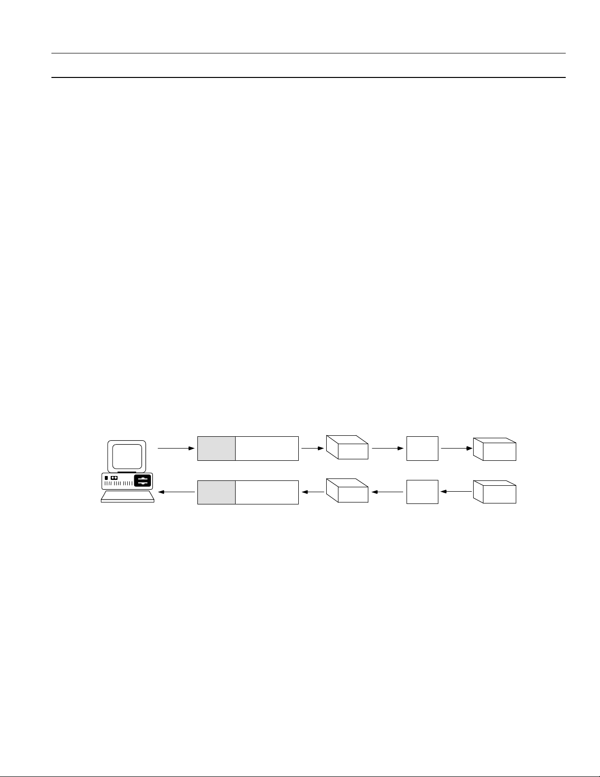
The Ethernet Gateway transparently passes message
between the host and devices attached to the
Gateway. Figure 5 illustrates the stripping or adding
of Ethernet headers to the Modbus messages. This
section describes the nature of these messages and
how the Gateway routes them. The following
information is not necessary for configuration and use of
the Ethernet Gateway, but is provided for users who may be
developing custom applications and need such
information.
Message Format
Messages sent from the software to RS485 devices
via the Ethernet Gateway have a 15-byte header
inserted in front of the message. The header tells
the Gateway where to send the message, how long
the message is, and if parity errors were
encountered. This header has the following format:
SS DD EE NN CC
SS Sequence of ten AA hex bytes indicating the start
of a message
DD Destination device port number – the Gateway
RS485 port to which the message should be
routed (0 - 3)
EE Error status byte (0 = no parity errors, 1 = parity
errors encountered)
NN Number of bytes in the Modbus message
CC A one byte checksum calculated by adding the
first 14 bytes in the header
The header is stripped off the message by the
Gateway and the remainder of the message is sent
without changes to the destination device (or
interpreted by the Gateway if a configuration
message).
Messages from the RS485 devices to the host are
processed by adding the 15-byte header onto the
start of the message. For messages from devices to
the host, the byte in the DD position contains the
RS485 port from which the message came.
Cyclic redundancy check (CRC) handling is done
by the host on the Ethernet and the RS485 device
on the Modbus. The Gateway does not check the
CRC when receiving messages from the host or
from RS485 devices.
Hos t
PMC S
Modbus messages fr om host to device - Ethernet Gateway str ips off header
Ethernet
header
information
Message tr aveli ng on Ether net
Ethernet
header
information
Mod bus
mess a ge
Mod bus
mess a ge
Modbus messages f rom device to host - Ether net Gateway adds header
Ethernet
Gateway
Ethernet
Gateway
Figure 5. Ethernet headers on Modbus messages.
Gateway/Host Interface
The Gateway uses TCP/IP (Transmission Control
Protocol/Internet Protocol) to interface with the
host on the Ethernet.
The Gateway initially opens a socket and waits for a
host device to attempt to connect with the socket.
Once a connection is established, data messages
may be transmitted to the Gateway (and ultimately
the RS485 devices) and messages from RS485
devices passed to the host.
Mod bus
message
Message t ravel ing on RS485
Mod bus
message
RS485
device
RS485
device
3
Page 8

POWER LEADER™ Ethernet Gateway
Chapter 1 – Introduction
1–4 Specifications
The specifications of the Ethernet Gateway are
listed in Table 2.
Parameter Value
Control power 90–132 Vac or 180–264 Vac,
47–63 Hz; autoranging
Power supply =150 VA min
(contact your GE sales
representative for additional
voltage options.)
Modbus communications Four RS485 ports, 1200 baud,
2400 baud, 4800 baud, 9600
baud and 19.2 Kbaud.
Ethernet communications One PCL-843 16-bit Ethernet
card; supports 10BaseT or
10Base2 transport mediums.
Standards
UL Listed
CSA Certified
Table 2. POWER LEADER Ethernet Gateway specifications.
508 & 840
C22.2 No. 14
1–5 Environmental Requirements
The environmental requirements of the Ethernet
Gateway are listed in Table 3.
Parameter Value
Operating temperature 0° C to +50° C
Storage temperature –20° C to +80° C
Relative humidity 10% to 95% noncondensing
Vibration response and
endurance
Fast transient surge ANSI C37.90.1
Radiated EMI withstand ANSI C37.90.2
Electrostatic discharge IEC 801–2
Table 3. POWER LEADER Ethernet Gateway environmental
IEC 255–21–1
Severity Class 1
Severity Class 4
requirements.
1–6 Terminology
Following are definitions of some of the terms used
in this document.
POWER LEADER – The GE family of comprehensive
power management devices and system software used
to minimize downtime and overall power cost.
PMCS – Power Management Control System software.
SCADA (supervisory control and data acquisition) – A group
of systems including power management and control
systems.
DCS (distributed control system) – A group of systems
including building automation and status
monitoring systems.
Ethernet – An open, industry-standard, high-perform-
ance network communications protocol that operates
on 10BaseT or 10Base2 transport mediums and
yields communications rates up to 10 megabits per
second.
Modbus RTU (Remote Terminal Unit) – An open, industry-
standard, high-performance network communications protocol developed by Modicon/AEG
Schneider Automation.
Modbus-compatible device – Any device equipped with a
Modbus RTU communications port.
Modbus master – A host computer running PMCS
software.
RS485/EIA485 – A physical standard for multi-drop,
high-speed, noise-tolerant communications over a
twisted pair network; often used with the Modbus
RTU protocol.
Commnet – A GE proprietary communications network
standard.
Commnet-compatible device – Any meter, relay, trip unit, or
other device equipped with a commnet communications port.
Commnet segment – A group of one to four commnet-
compatible devices (including at most one waveformcapturing meter) with all communication ports wired
to a single Concentrator commnet port.
4
Page 9

Chapter 2 – Installation
m
2–1 Mounting
The Ethernet Gateway may be mounted on a
horizontal surface or on a wall, preferably inside an
enclosure or switchgear lineup. The Gateway should
be mounted so that it is spaced from enclosure walls
or from other components in the enclosure. A
minimum of two inches clearance should be
allowed along the long sides of the Gateway, and at
least six inches clearance on the ends to allow for
ventilation and cable access. To wall mount the
Ethernet Gateway, attach the brackets to the chassis
using six of the provided screws through the six
holes on the inner edges of the mounting brackets.
Then use the remaining four screws to secure the
chassis to the wall through the holes in the outer
edges of the brackets. Be sure that the chassis is
mounted securely. The hole pattern for the
mounting flanges of the Ethernet Gateway is shown
in Figure 6.
12 i n. 1 in.
305. 0 mm 23.0 m
POWER LEADER™ Ethernet Gateway
Chapter 2 – Installation
Figure 7. Connecting control power to the Ethernet Gateway.
2–3 Ethernet Connection
10BaseT and 10Base2 connections are provided on
the back of the Ethernet Gateway to connect the
Gateway to the Ethernet network, as shown in
Figure 8. The Gateway is equipped with a PCL-843
16-bit Ethernet card.
7 - 1/8"
190. 6 mm
8 - R5 4 - R2.5
Figure 6. Mounting hole pattern for Ethernet Gateway.
2–2 Control Power Connections
Connect the control power cable included with the
Ethernet Gateway to the standard PC-style power
outlet on the rear of the enclosure, as shown in
Figure 7. See Section 1–4 for appropriate control
power voltage ranges.
The ON switch for the Ethernet Gateway is located
on the front panel. Make sure the Gateway is
mounted in a location where the power switch is
not likely to be accidentally hit or switched off.
Figure 8. Making the Ethernet connection to the Gateway.
5
Page 10

POWER LEADER™ Ethernet Gateway
Chapter 2 – Installation
2–4 Modbus Connection
The Modbus RTU networks should be connected to
the RS485 ports on the back of the Ethernet
Gateway, as shown in Figure 9.
Figure 9. Connecting an RS485 network to the Ethernet
Gateway.
Per the EIA-485 standard, the RS485 networks must
be terminated at both ends. Position the Ethernet
Gateway at one end of the RS485 networks, as it is
internally terminated. The user must ensure that
the final device on each network is terminated
correctly, as shown in Figure 10.
2–5 Diagnostic Connection
The RS232 port on the back of the Ethernet
Gateway is provided for connection of a dumb
terminal to the Gateway. The terminal may be used
for configuring the Ethernet Gateway’s settings or
for diagnostic purposes. For diagnostic purposes,
the Gateway may be set to display all messages and
traffic on the terminal so that problems may be
tracked down and corrected. To connect a terminal
(usually a laptop computer running Windows’
Terminal accessory software) to the Gateway, plug
its RS232 cable into the RS232 port on the back of
the Ethernet Gateway, as shown in Figure 11.
Figure 10. Terminating an RS485 network at the last device.
Figure 11. Connecting a dumb terminal to the RS232 port.
2–6 Wiring Rules – Modbus Networks
When wiring Modbus RTU devices to an Ethernet
Gateway, follow the wiring rules below to ensure
proper configuration. Refer to GEH-6502, the PMCS
Network Architecture Guide, for specific examples of
correct and incorrect configurations.
1. Up to 31 Modbus devices may be attached to a
single Modbus network. RS485 repeaters do not
have Modbus addresses, but do count as devices
toward the 31 physical devices per network limit.
2. Every device on a single Modbus network must
have a unique address. (Devices on different
networks may use the same Modbus address,
i.e., it is acceptable to have a device addressed as
device 10 on Network 1 and another device
addressed as device 10 on Network 2.) Use the
Modbus address worksheets (at the end of this
6
Page 11

POWER LEADER™ Ethernet Gateway
Chapter 2 – Installation
manual) to record the devices attached to each
network and verify that each device on each
network has a unique address.
3. Modbus Concentrators may be used to add
POWER LEADER commnet devices to a
Modbus network. The Concentrator assigns a
Modbus-equivalent address to each commnet
device attached to it. See Section 2-7 for a
discussion of commnet and Modbus-equivalent
addresses.
NOTE: While Modbus Concentrators are counted
as regular Modbus devices, the commnet devices
attached to Modbus Concentrators do NOT count
toward the 31 device/network limit, but ARE
considered in the 247 address/network limit.
4. No connections between Modbus networks are
permitted, either directly or through repeaters.
5. Modbus networks are constrained to a
maximum 4,000 feet of communication cable
without repeaters.
6. RS485 repeaters may be used to extend the
wiring length of a Modbus network or to
provide isolation between runs of cable in a
Modbus network. Refer to GEH-6502 for
appropriate wiring lengths with repeaters.
2–7 Modbus Equivalent Addresses
A maximum of 31 Modbus devices can be
supported on a single RS485 network of the
Ethernet Gateway. However, the Modbus RTU
protocol permits up to 247 individual addresses to
be recognized. These additional 216 addresses may
be utilized by commnet devices attached to a special
Modbus device, the Modbus Concentrator.
Commnet is a communications protocol utilized by
many of the devices from GE’s POWER LEADER
family of power management devices. The Modbus
Concentrator is a Modbus RTU device that permits
commnet devices to be assigned Modbus-equivalent
addresses. Each Modbus Concentrator keeps track
of up to 32 commnet devices and directs traffic
between the Modbus network and the commnet
devices. To the Modbus network, the commnet
devices appear as valid Modbus addresses.
To provide seamless integration of commnetcompatible devices into the Modbus RTU network,
the Concentrator directly maps commnet addresses
to equivalent Modbus addresses. The valid range of
commnet addresses recognized by the concentrator
is 300–514. These addresses are one-to-one mapped
to the equivalent Modbus address range of 33–247.
For a more detailed discussion of commnet devices
and the function of the Modbus Concentrator, see
GEH-6491, the Modbus Concentrator Users Guide.
Table 4 lists commnet devices supported by the
Modbus Concentrator (and the Ethernet Gateway).
Device Description
POWER LEADER EPM Full-function, three-phase electronic
meter with optional pulse initiation;
simple retrofit to existing
electromechanical installations. See
GEH–6302 for a full description.
POWER LEADER Meter Full-function three-phase meter with
optional protective relaying and
waveform capture. See GEH–5892.
POWER LEADER MDP
Overcurrent Relay
Spectra ECM™ Advanced motor protection in full-
MicroVersaTrip PM™ trip
unit in Spectra RMS™
molded-case circuit
breakers
MicroVersaTrip PM™ trip
unit in AKR, Power
Break® and Power
Break® II insulated-case
circuit breakers.
Table 4. POWER LEADER commnet devices supported by the
Three-phase and ground protection
against overloads and rapid
detection of short circuits.
See GEK–100682.
voltage-nonreversing (FVNR) and
full-voltage-reversing (FVR)
combination starter applications.
See GEH–6435.
Overcurrent protection and optional
full-function metering and protective
relaying. See GEH–5934.
Overcurrent protection and optional
full-function metering and protective
relaying. See GEH–6273.
Modbus Concentrator.
7
Page 12

POWER LEADER™ Ethernet Gateway
Chapter 3 – Configuration
Chapter 3 – Configuration
The Ethernet Gateway needs to be properly
configured to communicate with your RS485
networks. Two items are critical to proper
performance of your Gateway: the Gateway’s
Ethernet address and the RS485 port
communication settings. The Gateway’s Ethernet
address should be set so that the host software will
know how to address messages to the Gateway. You
must configure the Ethernet Gateway with the
appropriate baud rate and communications settings
for each RS485 port to match attached RS485
network. After initial setup, you should only need to
make changes to the Gateway’s settings after adding
devices or making system changes.
Follow the instructions in Section 3-1 to perform the
initial configuration. After the network is
operational, you may make configuration changes
through the dumb terminal. These procedures are
described in the following sections.
In all cases, be sure to save any configuration
changes to the Gateway’s hard drive (option 12) for
safe retrieval in the event of a power loss.
3–1 Configuration Procedure
Figure 12. Terminal communications settings.
You are now ready to configure the Gateway, as
outlined below:
1. Type SET (must be typed in capital letters)
then press <ENTER> to bring up the
configuration menu. If you make an error
typing in this string, wait ten seconds and try
again.
Configuration of the Gateway requires a dumb
terminal with RS232 port set to 19.2 Kbps, 8 data
bits, no parity, and 1 stop bit. The easiest way to do
this is to use a portable computer with an RS232
port, and run the Terminal accessory program from
Windows.
Use a null modem cable to attach the laptop to the
RS232 port of the Gateway, power up the laptop
and launch the Terminal program (located in the
Accessories program group in the Windows
program manager). Click on the Settings menu,
then choose Communications. Set your
communications options to look like figure 12.
When you have set your communications options,
close the options window and power up the Gateway
(the ON switch is located on the front panel).
When the Gateway finishes powering up, the
following message is transmitted to the terminal:
2. The terminal displays the configuration
menu:
Figure 13. Ethernet Gateway configuration menu.
8
Page 13

POWER LEADER™ Ethernet Gateway
Chapter 3 – Configuration
Enter the setting number you want to change,
then press <ENTER>.
NOTE: The lower portion of the Configuration Menu is
labeled Advanced Options. These options are for use
ONLY by GE technical support personnel. Do NOT select
any of these options. IF YOU ACCIDENTALLY SELECT
ANY ADVANCED OPTION FROM THE
CONFIGURATION MENU, PRESS <ESC> TO EXIT,
THEN PRESS <ENTER> TO RETURN TO THE
CONFIGURATION MENU.
3. At the prompt, enter the new setting, then
press <ENTER>. If you enter an invalid value,
the following message will be displayed:
Pressing <ENTER> returns you to the
configuration menu.
NOTE: Pressing <ESC> while entering a new value for a
setting discards the changes and redisplays the
configuration menu.
3–2 Ethernet Gateway IP Address
Ethernet Gateway’s IP address must be properly set
for it to receive messages sent by the host software.
Consult your LAN personnel or system
administrator for assistance in selecting the correct
IP address. Follow Section 3–7 to modify the IP
address.
WARNING: Setting the Ethernet Gateway to an incorrect
or conflicting IP address can cause SERIOUS network
problems. ALWAYS consult your LAN personnel or system
administrator before making any changes to the IP
address.
3–3 Baud Rate Specification
You must configure the baud rate and
communications settings on each RS485 port to
match the baud rate on the attached RS485
network. The Gateway supports RS485 speeds of
1200 baud, 2400 baud, 4800 baud, 9600 baud and
19.2 Kbaud. Default settings are 19.2 Kbaud, 8 data
bits, no parity, 1 stop bit.
4. Configure parameters as desired, by repeating
steps 2 and 3.
5. When you are finished making changes, select
option 12, .
The configuration file on drive A is modified
with the new parameters and the terminal
displays the following message:
If an error has been made, select option 13,
The
currently displayed settings are discarded and
the following message is displayed on the
terminal:
Correct the error by repeating steps 1–3.
6. When you have saved the configuration and
exited, the Ethernet Gateway is ready for
operation. Turn off the unit until the rest of
the network is ready for operation.
Each network’s baud rate depends on the devices
attached to it – see GEH-6502, the PMCS Network
Architecture Guide, for more details on this.
To configure the baud rate and communications
settings for any of the four RS485 ports, follow
Section 3-1, referencing the special instructions
given below regarding the communications options.
Table 5 lists the valid entries for options 1 through
8 of the Configuration menu, relating to the baud
rate and communications settings of RS485 ports.
9
Page 14

POWER LEADER™ Ethernet Gateway
Chapter 3 – Configuration
Option Number: Valid Entries at Prompt:
1 = RS485 Port 1
3 = RS485 Port 2
5 = RS485 Port 3
7 = RS485 Port 4
2 = RS485 Port 1
4 = RS485 Port 2
6 = RS485 Port 3
8 = RS485 Port 4
1. Follow the procedure outlined in Section 3-1
to configure the Gateway.
2. At the Configuration menu, select the option
number, then press <ENTER>. At the prompt,
enter the new setting, then press <ENTER>. For
options 1, 3, 5, and 7, enter the new setting
from the options in Table 5, then press
<ENTER>. For options 2, 4, 6, and 8, enter each
new parameter as prompted, using the correct
entries from Table 5. If you enter an invalid
value, the following message display:
Press <ENTER> to return to the Configuration
menu.
NOTE: Pressing <ESC> while entering a new value for a
setting discards the changes and redisplays the
Configuration menu.
0 = 1200 baud 4 = 19200 baud
1 = 2400 baud 5 = 38400 baud
2 = 4800 baud 6 = 57600 baud
3 = 9600 baud
Data Bits: 0 = 7 data bits
1 = 8 data bits
Stop Bits: 0 = 1 stop bit
1 = 2 stop bits
Parity: 0 = None
1 = Even
2 = Odd
Table 5. RS485 Port Settings .
3–4 Message Monitoring
For diagnostic purposes, you may want to monitor
message traffic across the RS485 ports. This can be
done on a terminal connected to the RS232 port.
You may monitor messages on any single RS485
port or on all four ports simultaneously.
Selecting menu item 14 allows you to select whether
or not messages are sent to the RS232 port in
monitor mode and which RS485 ports are to be
monitored. The following prompt appears:
Enter your selection from the above choices.
3–5 Ethernet Driver
Menu item 10 permits the Ethernet driver to be
selected. Most systems utilize DIX Ethernet; a
handful use IEEE Ethernet. The Gateway defaults
to the DIX Ethernet driver. If your network does not
function under DIX Ethernet and you have
eliminated all other potential sources of trouble,
change the driver setting to IEEE Ethernet and retry
communications. If this does not resolve the
problem, contact Customer Service.
3. Follow steps 5 and 6 of Section 3-1 to save any
changes and exit configuration mode.
10
Page 15

POWER LEADER™ Ethernet Gateway
Chapter 3 – Configuration
3–6 Gateway Diagnostics
Selecting menu item 11 exits the Gateway software
and runs the Gateway diagnostics program. The
Gateway Diagnostics menu shown in Figure 14 is
displayed on the terminal.
Figure 14. Gateway Diagnostics menu.
Display Socket, IP Address and Subnet
Mask
Select menu item 1 to display the IP address and
subnet mask for the Gateway.
RS485 Loop-back Test
Enter the port to be tested: 1, 2, 3, or 4. The
following message displays:
(where X is the port being tested).
If the loop-back is successful, the following message
will be displayed:
(where Y is the loop-back port).
If the loop-back is unsuccessful, the following
message displays:
Default settings on the RS485 ports for the loopback tests are 115.2 Kbps, 8-N-1.
Ethernet Test
Select menu item 3 to test the Gateway’s internal
Ethernet connections. This performs a self-test of
the Gateway’s Ethernet card to ensure that it is
functioning correctly. The following message
displays:
If the test passes, the following message displays:
Select menu item 2 to perform a loop-back test on
an RS485 port. The loop-back test is useful for
identifying the RS485 ports and for testing
communications on an RS485 port. To complete
this test, you will need a short RS485 cable, available
at an electronics retailer.
The RS485 port being tested is connected to
another RS485 port and a test message is
transmitted from the port being tested. The
following prompt appears:
If the test fails, the following message displays:
In either case, pressing <ENTER> returns you to the
diagnostics menu.
Exit Diagnostics Program
Select menu item 4 to exit the Gateway diagnostic
software and reload the Gateway software.
11
Page 16

POWER LEADER™ Ethernet Gateway
Chapter 3 – Configuration
Network Test – FACTORY USE ONLY
NOTE: A client program may be requested from GE to
run on the host when performing the network test. The
client attempts to establish a connection to a server (the
Gateway) with the specified IP address, subnet mask and
port number.
Menu item 5 is for factory testing of the network.
End users should NOT select this option. This test
attempts to communicate with a host across the
Ethernet. To complete this test, you will need an
RS232 null modem cable, available at an electronics
retailer. Before performing this test, the host PC
must be running the client software mentioned
above, and must be connected to the Ethernet
Gateway via the null modem cable.
When you select menu item 4, the following
message is displayed:
3–7 Advanced Options – Technical
Support Personnel ONLY
Ordinarily these options will have been configured
by the system integrator or direct from the factory;
you should NOT alter any of the settings from the
advanced options area of the Configuration menu.
WARNING: ALTERING ANY OF THESE SETTINGS
MAY RENDER THE ETHERNET GATEWAY
INOPERABLE. IF YOU ACCIDENTALLY SELECT ANY
OPTION FROM THE ADVANCED SETTINGS, PRESS
<ESC> TO EXIT, THEN PRESS <ENTER> TO RETURN
TO THE CONFIGURATION MENU.
Select menu item 15 to modify the Gateway socket
identifier. The format is: ####.
Select menu item 16 to modify the Gateway Internet
Protocol (IP) address. Enter the IP address in dot
notation, e.g., 123.145.51.126.
Select menu item 17 to modify the Gateway subnet
mask. Enter the subnetwork mask in dot notation,
e.g., 255.255.255.0.
If the network test passes, the following message is
displayed:
If the network test fails, the following message is
displayed:
In either case, pressing <ENTER> returns you to the
diagnostics menu.
Select menu item 18 to modify the FTP PC/TCP
kernal serial number. The number has the
following format: 1234-5678-9012.
Select menu item 19 to modify the FTP PC/TCP
kernal authentication key. The number has the following format: 1234-5678-9012.
Select menu item 21 to modify the Gateway Router.
This item has the following format: 0.0.0.0, 0.0.0.0,
0.0.0.0 Note that the Router numbers may have
multiple digits in each placeholder, and each set of
four numbers represents one router; for example,
205.109.43.11, 0.0.0.0, 0.0.0.0 is configured for one
router. The Gateway may be configured with a
maximum of three routers.
Updating the Gateway Software
Option 20 of the Configuration menu allows updating of the Ethernet Gateway’s operating software
and is for use ONLY by factory service personnel.
12
Page 17

Chapter 4 – Operation
The Ethernet Gateway, once properly configured,
requires no user intervention for operation.
During normal operation, the Ethernet Gateway
passes messages to and from the attached Modbus
devices and translates these messages between the
Ethernet and Modbus RTU protocols.
Should power to the Ethernet Gateway be interrupted, communications between the host and the
RS485 networks will resume automatically and
immediately when power is restored.
Likewise, if the Ethernet connection or any of the
RS485 connections are broken, communications
will be immediately resumed when the connections
are restored.
Any errors encountered by the Ethernet Gateway
will result in a message being sent back to the host,
where it will be interpreted and displayed for corrective action by the operator.
POWER LEADER™ Ethernet Gateway
Chapter 4 – Operation
All processing error messages are sent to the RS232
port. Processing error messages are listed in Section
5-1 of this manual.
13
Page 18

POWER LEADER™ Ethernet Gateway
Chapter 5 – Errors and Diagnostic Messages
Chapter 5 – Diagnostic Messages and Errors
5–1 Monitor Mode
The Ethernet Gateway can be set to send diagnostic
messages to the RS232 port to be displayed on a
terminal (see Chapter 3). These diagnostic
messages can be very useful in tracking down errors
in configuration or device addressing.
Diagnostic messages sent to the RS232 port in monitor mode have the following format:
Table 6 explains what each field means:
Field Meaning
The relative time of the message in timer
ticks. This rolls over every
1,000,000,000 timer ticks.
Indicates the direction of the message:
E-n (n = 1,2,3 or 4) indicates a message
sent from the Ethernet Gateway to
RS485 port number 1,2,3 or 4
n-E indicates a message sent from
RS485 port number 1,2,3 or 4 to the
Ethernet Gateway
Header byte added to regular Modbus
message. Printed as two hex digits.
Binary data of regular Modbus message.
Printed as two hex digits.
5–2 Processing Error Messages
Table 7 gives error messages that may be generated
by the Gateway and displayed at the PMCS host.
Message Meaning
Error - Buffer Overflow One or more buffers have
overflowed.
Error - Writing to Flash
ROM
Error - Reading Flash
ROM
An attempt to write to flash ROM
(drive A) has failed.
An attempt to read the flash ROM
(drive A) has failed.
Table 7. Error message key.
Table 6. Diagnostic messages key.
14
Page 19

POWER LEADER™ Ethernet Gateway
Chapter 6 – Troubleshooting Guide
Chapter 6 – Troubleshooting Guide
The following guide is provided for troubleshooting
and isolating common problems. It does not cover
every possible condition. Contact the ED&C
Customer Support Center at 800-843-3742 if the
problem is not resolved by these procedures.
Symptom Possible Cause Corrective Action
1. No response at either
host PC or dumb
terminal from the
Ethernet Gateway.
Lack of power.
Ethernet Gateway internal
failure.
Check that control power cable is working and
correctly connected.
Remove and reapply power to the Ethernet
Gateway to see if the failure clears itself
(possibly caused by external noise). Contact
Customer Support if the problem persists.
WARNING:
Voltages hazardous to personnel and equipment may
be present at the power connection.
2.
No response at host
PC from the Ethernet
Gateway, but terminal
connection is OK.
3.
Ethernet connections
OK, but no response
from RS485
device(s).
4.
Some devices on
RS485 networks not
recognized at host.
Faulty Ethernet wiring
between Ethernet Gateway
and host PC
Ethernet driver may be
incorrect.
Faulty RS485 wiring between
Ethernet Gateway and
RS485 networks.
Lack of control power at
RS485 device(s).
Addressing problems or too
many devices on segment
Check that the Ethernet connector is properly
wired and firmly seated. Test wiring for
continuity and polarity to host PC.
Check with your system administrator as to
which Ethernet driver is being used (DIX or
IEEE). Make sure Gateway is set accordingly
(Section 3-5).
Check that the RS485 connector is properly
wired and firmly seated. Test wiring for
continuity and polarity on RS485 wiring.
Check that control power present and correctly
connected at device(s).
Refer to Section 5-1 to diagnose the precise
problem and correct accordingly.
15
Page 20

POWER LEADER™ Ethernet Gateway
Configuration Worksheets
RS485 Port Configuration Worksheets
Use the following worksheets to record the devices
attached to the Ethernet Gateway for reference and
troubleshooting. Record the Ethernet Gateway’s
Ethernet address on the first page only, then fill in
the information on the Modbus devices attached to
RS485 Port 1 Worksheet
Baud Rate for RS485 Port 1
Modbus
Network
1 1
1 2
1 3
1 4
1 5
1 6
1 7
1 8
1 9
1 10
1 11
1 12
1 13
1 14
1 15
1 16
1 17
1 18
1 19
1 20
1 21
1 22
1 23
1 24
1 25
1 26
1 27
1 28
1 29
1 30
1 31
Device
Number Device Type & Physical Location / Notes
each network: device type and physical location,
and the Modbus address assigned to it.
Ethernet Gateway Address:
Modbus
Address
16
Page 21

Baud Rate for RS485 Port 2
POWER LEADER™ Ethernet Gateway
Configuration Worksheets
RS485 Port 2 Worksheet
Modbus
Network
2 1
2 2
2 3
2 4
2 5
2 6
2 7
2 8
2 9
2 10
2 11
2 12
2 13
2 14
2 15
2 16
2 17
2 18
2 19
2 20
2 21
2 22
2 23
2 24
2 25
2 26
2 27
2 28
2 29
2 30
2 31
Device
Number Device Type & Physical Location / Notes
Modbus
Address
17
Page 22

POWER LEADER™ Ethernet Gateway
Configuration Worksheets
RS485 Port 3 Worksheet
Baud Rate for RS485 Port 3
Modbus
Network
3 1
3 2
3 3
3 4
3 5
3 6
3 7
3 8
3 9
3 10
3 11
3 12
3 13
3 14
3 15
3 16
3 17
3 18
3 19
3 20
3 21
3 22
3 23
3 24
3 25
3 26
3 27
3 28
3 29
3 30
3 31
Device
Number Device Type & Physical Location / Notes
Modbus
Address
18
Page 23

Baud Rate for RS485 Port 4
POWER LEADER™ Ethernet Gateway
Configuration Worksheets
RS485 Port 4 Worksheet
Modbus
Network
4 1
4 2
4 3
4 4
4 5
4 6
4 7
4 8
4 9
4 10
4 11
4 12
4 13
4 14
4 15
4 16
4 17
4 18
4 19
4 20
4 21
4 22
4 23
4 24
4 25
4 26
4 27
4 28
4 29
4 30
4 31
Device
Number Device Type & Physical Location / Notes
Modbus
Address
19
Page 24

g
GE Electrical Distribution & Control
General Electric Company
41 Woodford Ave., Plainville, CT 06062
GEH-6505A 0996 © 1996 General Electric Company
 Loading...