

Page 1

GE Industrial Systems
Instructions
Direct Current Motors & Generators
GEH-5304A
Type CD
Frames 2512AT, 2513AT
Frames 2812AT, 2813AT
Page 2

GEH-5304A
These instructions do not purport to cover all of the details or variations in equipment nor to provide for every possible
contingency to be met in connection with installation, operation, or maintenance. Should further information be desired
or should particular problems arise which are not covered sufficiently for the purchaser’s purposes, the matter should be
referred to the General Electric Company.
© Copyright 1985, 1992, 1999 Gener a l El ectri c Company
2
Page 3

GEH-5304A
Table of Contents
Subject Page
Introductio n..............................................................................................................................5
Receiving..................................................................................................................................5
Storage ............................................................................................................................5
Handling ..........................................................................................................................6
Installation................................................................................................................................7
Location...........................................................................................................................7
Mounting .........................................................................................................................8
Alignment ........................................................................................................................8
Coupled Drive.........................................................................................................8
Alignment Procedure-Flexible Coupling, Non-Self-Supporting Bases..............8
Alignment Procedure-Flexible Couplings, Self-Supporting Bases.....................9
Grouting..................................................................................................................9
V-Belt Drives ..........................................................................................................9
Bearing Life.............................................................................................................9
Special Load Considerations..................................................................................11
Pinion Drives.........................................................................................................11
Thrust Loads.........................................................................................................11
Operation ................................................................................................................................11
Inspection Before Starting..............................................................................................12
Bearings and Couplings.........................................................................................12
Commutator and Brushes.......................................................................................12
Rectified Power Supplies.......................................................................................12
Power Supply Identificaiton ...................................................................................14
Connections...................................................................................................................15
Protective Devices..........................................................................................................15
Motor Field Heating.......................................................................................................15
Thermostats ...................................................................................................................15
Speed Limit Devic e ........................................................................................................16
Space Heater..................................................................................................................16
Ventilation System.........................................................................................................17
General Mechanical Inspection.......................................................................................17
Accessory Mounting ......................................................................................................18
Brakes............................................................................................................................18
Inspection After Starting................................................................................................18
Bearings................................................................................................................18
Noise and Vibration...............................................................................................19
Inspection After Short Time In Service..................................................................19
Maintenance............................................................................................................................19
Disassembly ...................................................................................................................20
Reassembly....................................................................................................................20
Bearings......................................................................................................................... 21
Replacement of Bearings................................................................................................ 21
3
Page 4

GEH-5304A
Subject Page
Brushes..........................................................................................................................22
Brush Removal With Machines Stopped and Power Off.........................................22
Brush Installation...................................................................................................23
Commutator...................................................................................................................24
Mechanical.....................................................................................................................25
Shaft End Play................................................................................................................25
Waterproof Machines.....................................................................................................25
Lubrication of Flexible Couplings ...................................................................................25
Insulation.......................................................................................................................25
Testing Methods ............................................................................................................26
Visual Inspectio n...................................................................................................26
Insulation Resistance Measurement........................................................................26
Cleaning of Windings ....................................................................................................27
Oily Dirt................................................................................................................28
Drying of Windings........................................................................................................29
Service Shop Cleaning....................................................................................................29
Repair ............................................................................................................................29
Renewal Parts.........................................................................................................................30
Storage of Renewal Parts ...............................................................................................30
Commutator Check Chart.......................................................................................................32
4
Page 5
Direct Current Motors and Generators
Type CD
Frames 2512AT, 2513AT, 2812AT, 2813AT
I. INTRODUCTION
This in struction book c ove rs the CD2512AT-CD2813AT line of DC motors and generators.
High voltage and rotating parts can cause serious or fatal injury. The use of
electric machi nery, like all oth er utilization of concentrated power and rotating
equipment, can be hazardous. Installation, operation and maintenance of electric machin ery should be performed by qualified personnel. Familiarization with
NEMA Safety Standard for Construction and Guide for Selection, Installation
and
Use of Integral HP Motors and Generators, National Electrical Code and sound local practices is
recommended.
These instruction s do not purport to cover all details or variations in equipment nor to provide for every possible
contingency or hazard to be met in connection with installation, operation and maintenan ce. Should further infor-
mation be desired or should particular problems arise wh ich are not covered sufficiently for the purchaser’s purposes, the matter should be referred to GE Industrial Systems.
GEH-5304A
II. RECEIVING
The equipment should be placed under adequate cover immediately upon receipt, as packin g covering s are NOT
suitable for out-of-doors or unprotected storage.
Each shipment should be carefully examined upon arrival. Any damage should be reported promptly to the carrier
and to the nearest office of GE Industrial Systems.
A. Storage
During installation or when in storage, the machine and its parts must be protected fr om the following:
1. Dirt of all kinds.
2. Wetness and temperature extremes.
Protection from dirt can be achieved by covering the machine with a tarpaulin or polyethylene sheet or
keeping it in a clean area.
Protection from wetness and temperature extremes includes moisture from the surrounding atmosphere condensing onto cooler machine surfaces. This condensation on machine surfaces can result in rusting or corrosion and the electrical windings may suffer serious damage.
Where wetness and/or cold conditions are present, the machine and its parts must be protected by a safe reliable heating system which, at all times, will keep the machine temperature slightly above t hat of the su rrounding atmosphere. If a space heater is included in the machine, it should be energized.
Smaller machines shipped in paper cartons are protected from condensing-type wetness by the insulating
characteristics of the carton. To avoid sweating where these have been exposed to low temperature for an
extended period, allow the machine and carton to attain room temperature before unpacking.
5
Page 6
GEH-5304A
Brushes should not remain in contact with the commutator during prolonged storage because corrosion may
occur and later result in flat spots on the commutator . Release the brush springs and lift the brushes when
stored for a period of more than six months.
All exposed machined steel parts are slushed with a rust preventative before shipment. These surfaces
should be examined carefully for signs of rust and moisture, and reslushed if necessary. Once start ed, rust
will con tinue if the surface is reslushed with out first removing all rust and moisture. Rust may be removed
by careful use of fine abrasive paper. Slushing compound can be removed by use of a suitable solvent such
as mineral spirits.
Mineral spirits are flammable and moderately toxi c. The usual precau tions for
handling chemicals of this type must be observed. These in clude:
1. Avoid excessive contact wi t h skin.
2. Use in well ven t ilated areas.
3. Take necessary precautions to prevent fire or explosion hazards.
Extreme care must be exercised in removing rust on shaft extensions near shaft seals, since it is difficult, and
sometimes impossible, to remove rust from these surfaces without damaging or deforming them.
Burrs or bumps on other machined surfaces should be carefully removed by using a fine file or scraper.
Machines in storage should be inspected, have the insulation resistance checked at fr equent and regular intervals (refer t o Insulation Resistance section), and a log kept of pertinent data.
When stored, it is suggested that the armature be rotated every t hree mo nth s to
prevent loss of grease protection on the bearings and races. Loss of grease
protection causes rust.
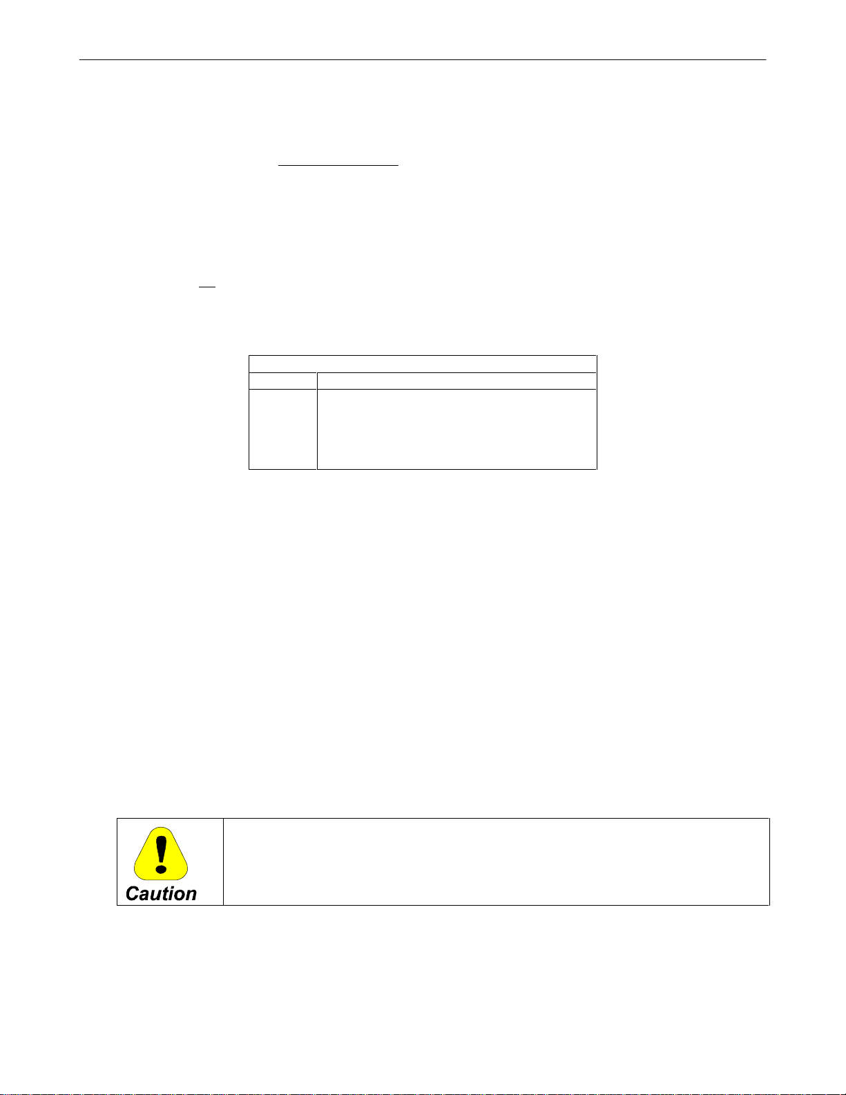
B. Handling
Complete motors or generators can be lifted by using hooks or slings in the lifting lugs of the unit. The lifting lugs are designed to safely carry the weight of the individual machine. DO NOT
the shaft extensions.
lift the machine with
Motor generator sets or units with heavy attachments such as gear boxes or
pumps must not be lifted by using the lifting lugs of the individual machines.
Motor generator set bases have lifting holes, to be used with spreader bars or hooks. Care must be taken in
handling to avoid twisting bases.
6
Page 7
Table 1
Typical Weights**
Motor (Less
Accessories) Armature
CD2512AT 500 120
CD2513AT 550 135
CD2812AT 650 160
CD2813AT 750 190
**Typical weights. For speci fic weight, see certi fied outline.
III. INSTALLATION
Installation should be in accordance with the Nation al Electrical Code and consistent with all local codes. Coupling, belt and chain guards should be installed as needed to pr otect against accidental contact with moving parts.
Machines accessible to the public should be further guarded by screening, guard rails, etc. to prevent personnel
from coming in contact with the equipment. Fully guarded covers are supplied on motors and generators. Shaft
guards are supplied on motor generator sets.
Totally enclosed and waterproof motor s must have all covers securely in place with gaskets intact in order to exclude dirt, oil and water. It is generally preferred to r emove plugs from drain holes at the bottom of the frame to
ensure that no condensation will collect inside the motor . However, if the installation requires plugs to be installed,
they must be removed periodically to make certain that all water is eliminated.
GEH-5304A
A. Location
Motors and generators should be installed so that they will be readily accessible for routine inspection and
maintenance. They are suitable for use in ambient temperatures fr om 0°C (32°F) to 40°C (104°F). An adequate supply of clean, dry room air is required for self-ventilated, separately ventilated and blown motors.
Where motors must operate in dirty, wet or contaminated environments, protection in the form of filters or
totally enclosed construction must be used to obtain long life with normal maintenance.
Do not obstruct ventilating openings.
When filters are supplied, service them regularly. Dirty filters shut off ventilating air .
Bewar e of recirculation. Install motors so that hot exhaust air will not re-enter the motor.
The use of electrical equipment in hazardous locations is restricted by the National Electrical Code, Article 500. Original equipment manufacturers and user
customers must read, understand and apply these rules for installation and use
of all equipment in such locations and consult local code inspection and en-
forcement agencies, as necessary, to ensure compliance. Motors listed by
Underwriters Laboratories, Inc. for use in specific locations have been designed, tested and approved for use in such locations only.
Sections 501-8 and 502-8 now permi t the use of tot ally enclo sed motors with positive pressure
ventilation or totally enclosed inert-gas-filled motors (Class I locations only), when installation
and operat ion conform to certain requ irements.
Motors for Class I locations must have leads sealed at the frame exit and an explosion-proof
conduit box. See Sections 501-4 and 501-5.
Motors for Class II locations must have leads sealed at the frame exit an d a dust-ignition-proof
conduit box. See Sections 502-4 and 502-5.
7
Page 8
B. Mounting
Motors and generators should be mounted on rigid and solid foun dations. Level the base (or the machine).
Hold-down bolts should be inspected regularly and kept tight. The feet of the machin e may be doweled to
the foundation plates or base when alignment procedures are completed. Sliding bases, when used, should
be securely anchored to the foundation.
Motors are mechanically suitable for mounting with shaft horizontal or vertical on floor, ceiling or sidewall.
When sidewall or ceiling mounted, special provisions must be made to maintain the integrity of dripproof
enclosu res.
When motor is sidewall or ceiling mounted, lifting points in addition to the
standard lifting lugs may be required. Lifting, in these cases should be done by
experienced riggers to avoid injury to personnel and damage to the moto r.
C. Alignment
Be sure to align or check alignment carefully on either motors or motor genera-
tor sets. Misalignment can cause excessive vibration and damaging forces on
shafts and bearings.
GEH-5304A
Time taken to assure good alignment will be returned in reduced downtime.
1. Coupled Dr ive
When a motor is used to dr ive a unit, flexible couplings must be used to facilitate alignment. Threebearing construction requir es a r i gid coupling.
Careful alignment of machines when using either solid (rigid) or flexible cou-
plings is essential to prevent excessive vibration and bearing or shaft failures.
D $OLJQPHQW3URFHGXUH
)OH[LEOH&RXSOLQJ1RQ6HOI6XSSRUWLQJ%DVHV
Before grouting the base, the coupling should be checked as follows:
1. Sl ide the sleeve from the coupl ing so t hat th e hub faces are ex posed.
2. Check that the coupling h ub spacing is in accor dance with the outline dimensions with
the units in the mechanical center of their end play.
3. Check parallel alignment by using a straightedge across the hubs at both vertical and
horizontal locations, or by clamping a dial indicator to one hub and indicating the other
hub on its outside diameter. Be sure that the dial indicator supports do not bend or sag,
since this will give inaccurate readings.
4. Use a dial indicator at hub faces and rotate both units together 90°, 180°, 270° and 360°
or measure the gap at each position by inserting a feeler gage. The reading should not
vary more than 0.002”.
5. Correct any vertical misalignment by shimming between the base and the foundation.
8
Page 9

Horizontal alignment should be corrected by shifting machines on the base.
b. Ali gnment Proc edur e
Flex ible Coupl ings, Self-Supporting Bases
Before operating the machine, the base should be bolted down and the alignment checked as
follows:
1. Remove all of the coupling bolts and slide the shells back so that the hub faces are exposed.
2. Check the coupling hub spacing in accordance with the outline dimensions with the
units in the mechanical center of their end play.
3. Check parallel alignment by using a straightedge across the hubs at both vertical and
horizontal locations or by clamping a dial indicator to one hub and indicating the other
hub on its outside diameter. Be sure that the dial indicator supports do not bend or sag,
since this will give inaccurate readings.
4. Use the dial indicator at hub faces and rotate both units together 90°, 180°, 270° and
360° or measure the gap at each position by inserting a feeler gage. The readings should
not vary more than 0.002”.
GEH-5304A
5. Correct any vertical misalignment by shimmin g under the units. Horizontal alignment
should be cor rected by shifting machine on the base.
2. Grouting
On concrete foun dations, a minimum of 1” should be allowed for grouting.
A rich, non-shrink grout should be used. High-grade grout mixtures are available commercially. If
the grout is to be prepared at the site, a cement-sand ratio of 1:2 is recommended. No more than
enough water should be used to give a stiff mixture. The clean but rough surface of the foundations
should be wet and the gr out forced or puddled under the base.
3. V-Belt Drives
The V-belt system produces a heavy shaft and bearing loading, making it necessary that these factor s
be considered carefully for proper application. Since belt drives impose a bending moment on the
motor shaft, it is always desirable to h ave the motor sheave located as close to the motor bearing as
possible to minimize both bearing load and shaft stress. This will result in increased bearing life. For
the load centered 2” in toward th e bearing from the end of the shaft instead of at the end of the shaft,
the bearing load is reduced by 10% an d th e life increased by 33%. The bearing life curves that follow
assume the load is centered at the end of the shaft. New improved V-belts are now on the market that
significantly reduce the number and size of belts required for a given load. These new belts should
always be considered, since the sheave will be shorter and the load centered closer to the bearing.
The standard NEMA shaft extension is designed for belted loads. Dimensions are provided on the
standard dimension sheets. A sliding base is available as an accessory to facilitate belt adjustment.
4. Bearing Life
Bearing life for belted drives is determined by calculating the radial load at the end of the shaft.
9
Page 10
GEH-5304A
The radial load, W, produced by th e belts when tightened just enough to transmit the load with out
slipping is given by the relation:
126,000 x HP
W = x K
, lbs
b
D x RPM
Where:
D = Sheave pitch diameter in inches for V-belt application
HP
RPM
K
=
Maximum ratio of horsepower, including overloads, to the minimum speed at which that
power occurs.
= Belt tension factory from table below:
b
Belt Tension Factor, K
K
b
b
Description
1.0 Chain and Sprocket Dr ive
1.2 Tim ing Belt
1.5 V-Belt, 1:1 Ratio
1.8 V-Belt, 2:1 Speed Decreased Ratio
2.0 Flat Belts
The curves that follow can be used to determine the anticipated L10 life, which is the life in hours that
90% of bearings with th is load would be expected to exceed withou t failure. The standard ball bearing and standard shaft option will be the most economic, if acceptabl e life i s obtained from the curve.
A good commonly used design figure is 20,000 hours. However , applications with a calculated life of
as low as 5,000 hours have sometimes been necessary to limit belt speeds to 6,000 feet per minute.
The curves are drawn for 1750 RPM average speed. If the application has some ot her average speed,
the life can be adjusted by multiplying by th e bearing life factor.
It is important to know that bearing life for V-belt applications is independent of the motor load.
Once the belts have been tightened just enough to prevent slipping when the maximum torque is being
delivered by the motor the radial load, W, on the shaft and bearing is there and r emains constant regardless of whether the motor is even turning. For timing belts and chain drives, the radial load, W,
does not vary somewhat with motor load. Therefore, the motor load duty cycle as well as the average
speed should be considered to estimate bearing life.
Belt tension should be checked and adjusted following the belt manufacturers’ recommendations.
If slippage occurs after the belt tension has been correctly adjusted, the belts and pulleys have not been
chosen properly for the application.
Over-tightening to avoid this slippage may result in early failures of belts, shafts
and bearings.
There is normally a drop in tension during the first 24 to 48 hours of operation. During this “run in”
per iod, th e belts sea t th emselves in th e shea ve grooves a nd in itial stretch is removed. Belt tension
should be re-checked after a day or two of operation.
Matched belts run smoother and last longer. Longer belt life results if the belts and sheaves are kept
clean and the belts are prevented from rubbin g against the belt guards or other obstructions.
10
Page 11
Mounting may be either horizontal or vertical for these bearing life determinations, as long as no axial
load (i.e., suspended load) other than the weight of the armature is present if vertical.
5. Special Load Considerat ions
Where the load is overh ung beyond the motor shaft extension or greater bearing life is desired, the
application should be referred to GE Industrial Systems.
6. Pi nion Drives
While Kinamatic motors are not designed for overhung pinion drives, they may be successfully applied under suitable conditions. In addition to a radial load, some gears produce thrust load on the
bearing. Complete details of the proposed gearing should be referred to GE Industrial Systems in all
cases.
7. Thrust Loads
Due to the mounting position or type of drive arrangement, a thrust load may be applied to the motor
shaft. The Kinamatic motor is designed to permit a limited amount of thrust load. This permissible
load will vary by mounting position and direction of the load due to the weight of the armature. The
permissible load in Table 2 is tabulated by frame diameter and mounting position. These apply to
ball bearings only.
GEH-5304A
For applications combin ing thrust and radial loads or where thrust loads exceed th e values sh own in
Table 2, refer all details to GE Industrial Systems.
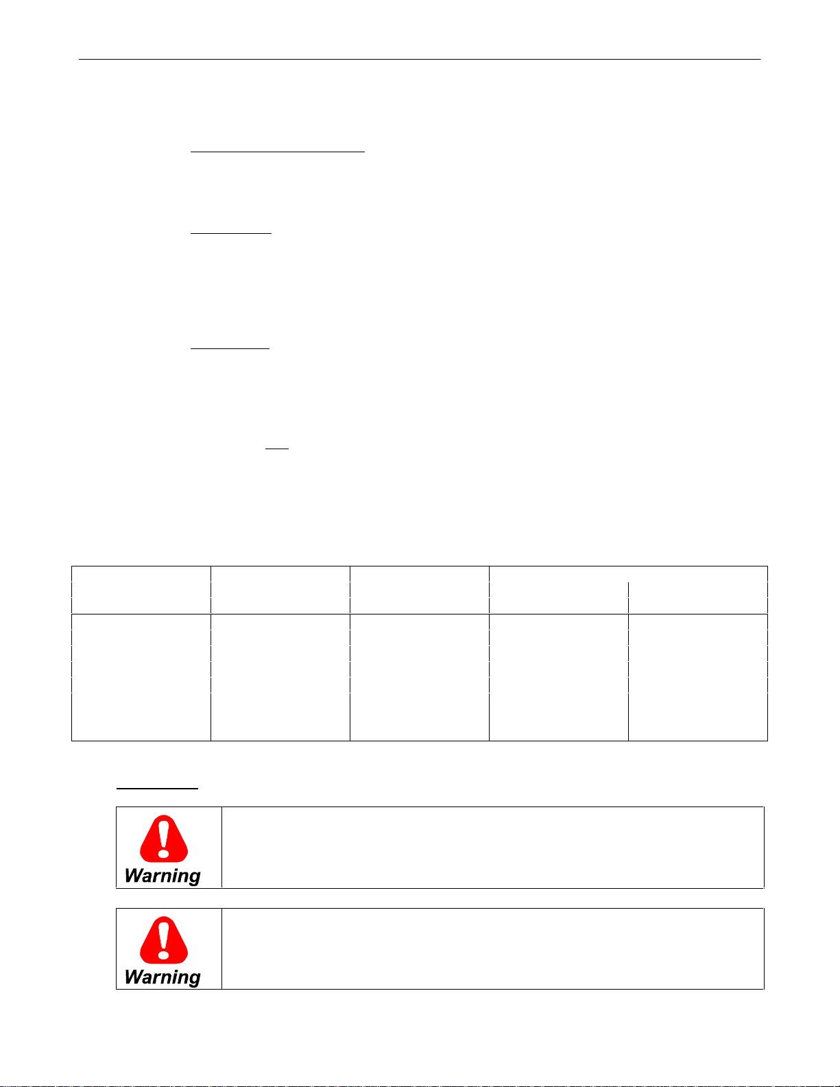
Table 2
Maximum Continuous Thrust Capacity, Lbs.*
Vertical Mounti ng
Bearing Horizontal Thrust Load Thrust Load
Frame Size Mounting Up Down
2512 Std-309 350 465 235
2512 O/S - 310 400 515 285
2513 Std-309 350 485 215
2513 O/S - 310 400 585 265
2812 Std-310 400 550 250
2812 O/S - 311 500 650 350
2813 Std-310 400 585 215
2813 O/S - 311 500 685 315
*Based on L10 life of 20, 000 hour s and an average speed not ex c eeding 2500 RPM.
IV. OPERATION
Disconnect power before touching any internal part. High voltage may be present even wh en the machine is not rotating. If used with a rectified power supply, disconnect all AC line connections to power supply. With other power
supplies, disconnect all DC line and field connections. Also disconnect power
from auxil iary devices.
Ground the machine properly to avoid serious injury to personnel. Grounding
must be in accordance with the National Electrical Code and consistent with
sound local practices. One of the bolts holding the conduit box to the unit, accessible from inside the conduit box, is identified and may be used for attach ing a grounding cable.
11
Page 12

Before starting the motor, remove all unused shaft keys and loose rotating parts
to prevent t hem from flying off.
A. Inspection Before Star ting
These inspection procedures should be followed befor e starting the machine for the first time, after an extended shutdown or after a teardown for extensive maintenance or repair.
1. Bearings and Couplings
Machines with ball or roller bearings are greased at the factory an d will need no attention until r elubrication is necessary as suggested in the Maintenance section of thi s in struction book.
If the flexible couplings are a lubricated type, they should be checked to see that they contain the
proper amount of lubricant.
Make sure that all grease plugs are tight.
2. Com mutator and B r ushes
GEH-5304A
Brushes should be worn in to ha ve at least 85% contact over the brush surface and continuous contact
from heel to toe. The commutator surface and undercut mica should be clean and free from dirt,
grease, paint spots or brush dust.
Brushes should be free to move in the holders and all springs should be down and latched. Brush
pigtail connections should be tight and the pigtails should not interfere with the action of the spring or
brush and should be clear of any other part of the machine.
B. Rectified Power Suppl ies
When DC motors are operated from rectified power supplies, the pulsating voltage and current wave forms
affect the motor perfor mance by increasing motor heating and degrading commutation. Because of these effects, it is necessary th at th e motors be designed or specially selected to suit this type of operation.
The ratings of DC motor s intended for operation from rectified power supplies are based upon motor tests
using a suitable power supply. The specific characteristics for three-phase rectified power supplies described
in the Power Supply Identification section are in common use. For operation of motors from rectified
power supplies other than those given in this section, refer to GE Industrial Systems.
A motor may, under some conditions, be operated from a power supply different from that indicated on the
nameplate. Letters used to identify power supplies in common use have been chosen in alphabetical order of
increasing magnitude of ripple current. Power supply compatibility can be judged by Table 4.
12
Page 13
GEH-5304A
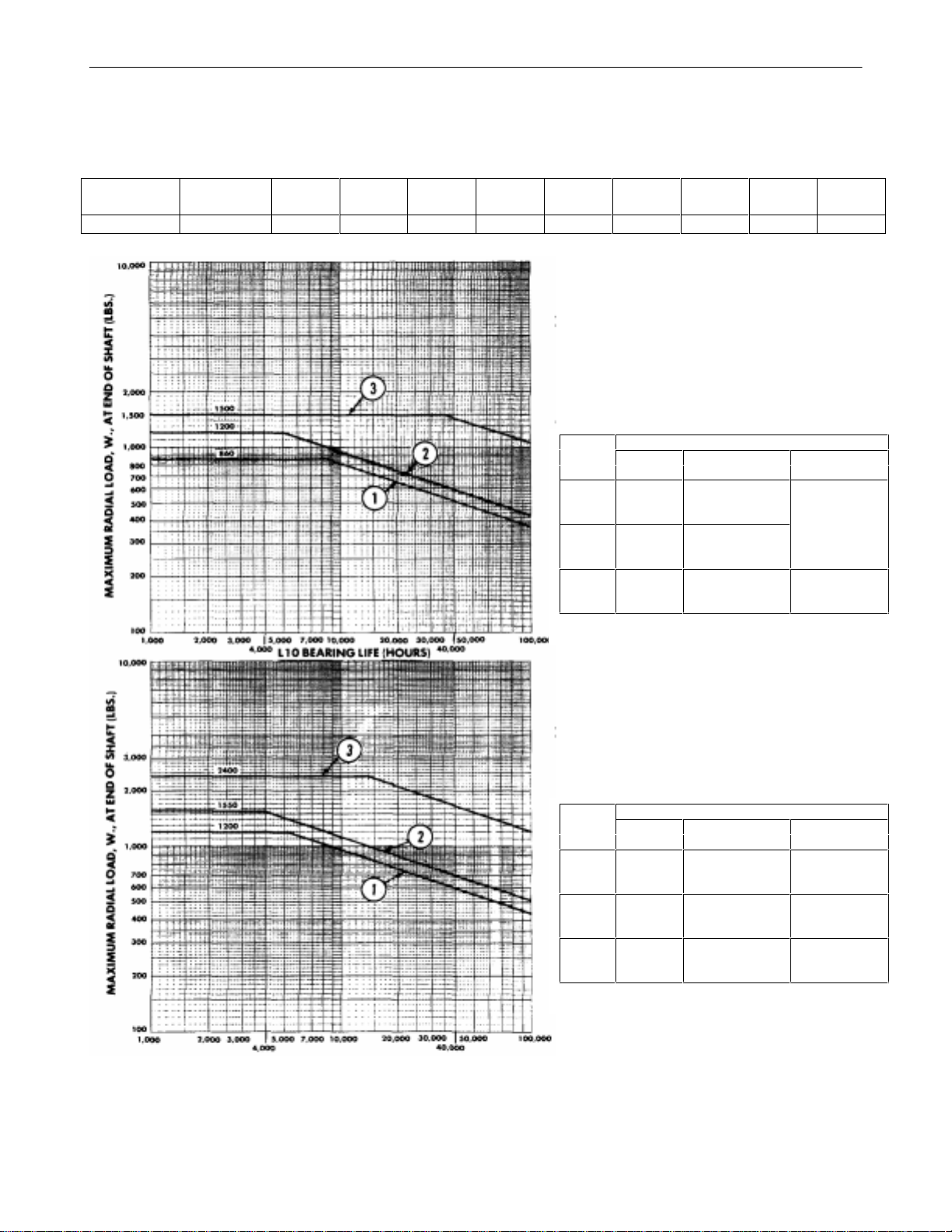
Table 3
Bearing Life at 1750 RPM Average Speed Vs. Load , W
(For other average speeds, m ultiply li fe by l ife factor)
Less Than
Speed 500 650 850 1150 1500 2000 2500 3000 4000 5000
Life Factor 2.15 1.83 1.55 1.29 1.10 .92 .80 .72 .60 .55
Frame Sizes
CD2512AT and CD2513AT
Description
Curve Bearing Diameter Material
1 Standard
Ball
(309)
2 Oversize
Ball
(310)
3 Oversize
Roller
(310)
Shaft Shaft
Standard (1-5/8) Standard
Oversize (1-7/8) Standard
Oversize (1-7/8) Special
Frame Sizes
CD2812AT and CD2813AT
Description
Curve Bearing Diameter Material
1 Standard
Ball
(310)
2 Oversize
Ball
(311)
3 Oversize
Roller
(311)
Shaft Shaft
Standard (1-7/8) Standard
Oversize (2-1/8) Standard
Oversize (2-1/8) Special
13
Page 14

Table 4
Power Supply Available
ACDEK
NP Rating Code
A
C
D
E
K
√
√√
√√√
√√√√
√√√√√
****
***
**
*
√ Compatible power supply.
* External inductanc e may be necessary to limit ripple current.
C. Power Supply Identification
The nameplates of DC motors intended for operation from rectified power supplies will be stamped with a
power supply identification as described below.
1. When the test power supply used as the basis of rating is one of the five described below, a single
letter "A”, “C”, “D”, “E” or “K” will be used to identify the test power supply.
GEH-5304A
a. Power Supply Identification Letter “A ”
This designates a DC generator, battery or any power supply with enough series inductance to
result in no more than 6% peak-to-peak armature current ripple.
b. Power Supply Identification Letter “C”
This designates a three-phase, 60 hertz input, full-wave power supply having six total (controlled) pulses per cycle. The power supply has no free-wheeling and no series inductance.
The input line-to-line AC voltage to the rectifier shall be 230 volts for 240 volt DC motor ratings, and 460 volts for 500 or 550 volt DC motor ratings.
c. Power Supply Identi fic ation Letter “ D”
This designates a three-phase, 60 hertz input, semi-bridge power supply having threecontrolled pulses per cycle. The supply has free wheeling with no series inductan ce added externally to the motor armature circuit. The input line-to-line AC voltage to the rectifier shall be
230 volts for 240 volt DC motor ratings and 460 volts for 500 or 550 volt DC motor ratings.
d. Power Supply Identification Letter “E ”
This designates a three-phase, single-way (h alf-wave) power supply having three total pulses
per cycle and thr ee-controlled pulses per cycle. The power supply has no free wheeling a nd n o
series inductance added externally to the motor armatur e circuit inductance. The input line-toline AC voltage to the rectifier shall be 460 volts for 240 volt DC motor ratings.
e. Power Supply Identification Letter “K ”
This designates a single-phase, full-wave power supply having two total (controlled) pulses per
cycle with free wh eeling 60 hertz input and no series inductance added externally to th e motor
armature circuit. The input AC voltage to the rectifier shall be 230 volts for 180 volt DC ratings.
14
Page 15

2. When intended for use on a power supply other than “A”, “C”, “D”, “E” or “K”, the motor will
be identified as follows:
M / N F - V - H - L
Where M = A digit indicating total pulses per cycle
N = A digit indicating controlled pulses per cycle
F = Free wheeling (this letter appears only if free wheeling is used)
V = Three digits indicating nominal line-to-line AC voltage to the rectifier
H = Two digits indicating input fr equency in hertz
L = One, two or three digits indicating the series inductance in millih enries (may
be zero) to be added externally to the motor armature circuit inductance.
D. Connections
Terminal connection s should be checked against the connection diagram shipped with the machine. Bolted
connections must be tight. All exposed con nections in the conduit box must be insulated. When more than
one terminal is marked with the same identification, they should be joined in the same connection. (Refer to
Table 6 for identification of wir in g leads.)
E. Protective Dev ices
GEH-5304A
Make certain that all protective devices (overspeed devices, bearing temperature relays, etc.) are connected and function properly. Also, make certain that
all coupling guards, shaft protectors, grounding connectors, covers and other
safety devices are properly at t ached.
F. Motor Field Heating
MOTOR FIELD HOUSING – Unless specifically ordered, motors are NOT cap abl e
of continuous standstill excitation at rated field current. When the motor is shut
down for more than 30 minutes, one of the following options must be used:
1. De-energize the fiel ds completely.
2. Use field economy relays to limi t the field cu rrent to a maximum of 50% of
the nameplate rating.
3. When applicable, fields may remain fully energized if the motor ventilation
system (blower or customer duct) remai ns in operation.
G. Therm ostats
The thermostat is a device that may be used in alarm or protective relay circuits within rating limits shown
in Table 5. It is not intended to limit motor loading or provide normal insulation life. When supplied, it is
mounted to a commutatin g coil wh ich is the only accessible part of the armature circuit. Since factors such
as shaft speed, ventilation (blower or shaft fan), current ripple (SCR phase-back) and short-time overload
affect the temperature relationship between armature and commutating field, complete protection from all
conditions resulting from over-temperature is not possible. The device is intended to guard against complete
loss of normal ventilation air, high ambient temperature, and prolonged operation of self-ventilated motors
at very low speeds.
15
Page 16

Thermostats automati call y reset after th e moto r has cooled somewhat. In order
to prevent pro perty d amage o r injury to personnel, the control circuit should be
designed to prevent re-energi z ing of the motor when the thermostat resets.
Table 5
Maximum Current Ratings for Thermostats
on Dripproof and Totally Enclosed Motors
(Normally open or normally closed con tacts)
Load 125 VAC 250 VAC 600 VAC 30 VDC
Do not use above 600 VA C or 30 V DC
Resistive 5Amps 2.5Amps 1Amp 5Amps
Inductive* 3 Amps 1.5 Amps 0.5 Amps 1.5 Amps
*Suitabl e for pi lot duty only (relay c oils).
H. S peed Limit Device
The mechanical speed limit device is non-adjustable. Tripping speed is specified by a note on the print certification for each specific order.
GEH-5304A
The speed limit electrical contacts are normally closed and are usually connected in r elay or holding circuits.
Current ratings are the same as those listed in Table 5.
A speed limit device is furnished on machines only when ordered.
The cont acts of th e speed li mit devi ce auto mati call y reclo se after th e speed has
fallen below the trip value. In order to prevent property damage or injury to
personnel, the control circuit should be designed to prevent re-energiz ing the
motor un t il the cau se of t he overspeed has been corrected.
Table 6
Lead Markers
Function Winding
Armatur e A1, A2
Field ( S hunt) F1, F2, F3, F4, etc.
Stator, AC Machines Only T1, T2, T3, T4, etc.
(Type AN Tachometer G ener ator)
Accessories & Special Device Markings
Tachomet er Generator, Direct Current, to Ter minal Board A1, A2
Brake Coil Leads B1, B2, B3, B 4, etc.
Heater, Brake S pac e Heater BH1, BH2, BH3, B H4, etc.
Brake Interlock Switch BS1, BS2, BS3, BS4, etc.
Heater, Space Heat er in the Machine H1, H2, H3, H4, etc.
Thermostat P1, P2, P3, P4, etc.
Resistance Temper ature Detector ( RTD) R1, R2, R3, R4, etc.
I. Space Heater
When furnished, see Print Certification for Electrical Ratin g.
Space heaters are furnished in machines when ordered. They should be energized with the correct AC voltage as shown on the nameplate.
16
Page 17

The surface of a space heater bl ock beco mes hot wh en the h eater is energiz ed.
The temperatu re rise above the amb ient temperatu re may be as high as 400
Avoid touching heater blocks which have recently been energized to prevent
burns. Also, t o prevent fire or explosion, ignitable dust or lint should not be
allowed to collect around the surface of the heat ers.
J. Ventilation System
Blowers or central systems must be in operation to supply cooling air before loading force ventilated machines. Air filters should be in place. Blowers should be checked for correct rotation. See outline or rotation arrow.
GEH-5304A
°
C.
Figure 1
Correct Arrangement O f Blower Housing, Impeller Blades,
And Direction Of Rotation To Obtain Proper Pressure And Air Flow
K. General Mechanical I nspect ion
Check the inside of the machine for tools, metal chips or any oth er foreign material that may have accumulated during storage or installation. Make sure that all rotating parts have clearance from any stationary
parts. Turn the machine over by hand, if possible, and check for scraping noises or any other sign of mechanical interference. Check the tightness of the bolts in the feet, couplings, bearing housings and any other
bolts that may have been disturbed.
Standard motors, as shipped, are assembled with bolts without lubricant (dry
threads). Wh en n ecessary, bolts may be replaced with bolts with dry threads or
with bolts lubricated with a motor oil or other suitable thread lubricant. When
lubricated threads are used, reduce torque to 65% of the value shown. The
torque values shown, when applied to bolts with lubricated threads, can cause
excessive bolt tension and possible bolt breakage.
17
Page 18

Table 7
Bolt Tightening Torque Values
Hex Head (C1C5) Grade 5
Medium Carbon Steel
Thread Sizes (Without Lubricant)
(UNC-2A) Lb-Ft N-m
1/4-20 7-9 10-12
5/16-18 13-17 18-23
3/8-16 24-30 33-40
1/2-13 60-75 80-100
5/8-11 120-150 160-200
3/4-10 210-260 280-350
For lubricated bolts, use 65% of value shown in Table 7.
L. Accessory Mounting
Provisions for mounting accessories on the commutator endshield is a standard feature. The rabbet has
NEMA type C-Face mounting dimensions, including the mounting bolt h oles. The standard stub shaft also
permits coupling certain accessories.
GEH-5304A
To prevent injury from the rotating shaft, the stub shaft cover must be maintained in position when the accessory mounting is not used.
Standard accessories are available as kits. These include a variety of tachometers, speed limit switches and
brakes. A mounting adapter, which can be machined for various accessories, can be ordered separately.
M. Brakes
Flange mounted brakes may be mounted on the accessor y rabbet. Since the accessory stub shaft is not suitable for use with a brake, the standard NEMA commutator end shaft extension should be or dered when such
use is planned. Standard brakes are designed for horizontal floor mounting only. When motors are sidewall
or ceiling mounted, the br ake must be reassembled to maintain its relation to the horizontal. Where motors
are to be mounted with the shaft greater than 15° from the horizontal, special brakes should be specified.
Improper selection or installation of a brake and/or lack of maintenance may
cause brake failure, which can result in damage to property and/or injury to
personnel. (Refer to the separate instruction book pertaining to the brake furnished.)
N. Inspection After Starting
The following items should be checked after the machine is running:
1. Bearings
Ball bearing or roller bearing housing temperature should be no more than 80°C (176°F). Excessive
bearing temperature may be caused by misalignment or improper greasing (Refer to Alignment and
Bearing Maintenance sections.)
18
Page 19

2. Noise and Vibration
Check for unusual vibration or noises that might indicate rubbing or interference.
Vibration of new machines at the bearing housings, as measured by a vibration meter, should not exceed th e valu es shown in Table 8. (Measurements are according to NEMA MG 1-12.06 and MG 1-
12.07.)
The most likely cause of vibration in new machines is misalignment due to improper installation,
loose foot bolts, uneven shimmin g under feet, or damage to machin e during shipment or installation.
Current ripple due to a rectified power supply may also be a source of vibration and audio noise.
Table 8
Maximum Amplitude
(in Inches)
RPM (Peak to Peak)
3000-4000 incl. .001
1500-2999 incl. .0015
1000-1499 incl. .002
999 and below .0025
GEH-5304A
3. Inspection After Short Time in Service
New machines may smell warm or have the odor of var n ish, but should not smell scor ched.
After a machine has been operating for a short time, an inspection should be made to ascertain that
there have been no changes since installation. Check for increased vibration, signs of change in
alignment or foundation settling, bolts that may h ave loosened, rubbing parts, loose connections and
worsened commutation. Proper steps must be taken to correct the trouble. Also, check the condition
of air filters on blower ventilated machines. The amount of dirt in the air varies widely between installations.
V. MAINTE NANCE
High voltage electric shock may cause serious or fatal injury. Disconnect power
before touching any internal part. High voltage may be present even when th e
machine is not rotating. If used with a rectified power supply, disconnect all AC
line connections to the power supply. With other power supplies, disconnect
all DC line and field connections. Also, disconnect power from auxiliary devices.
Ground the machine properly to avoid serious injury to personnel. Grounding
must be in accordance with the National Electrical Code and consistent with
sound local practices.
Replace covers and p rotective devices before operating.
19
Page 20

A. Disassembly
The following procedure should be used for disassembly:
1. Remove all covers.
2. Disengage brush springs.
3. Remove complete brushholder assemblies.
4. Remove four (4) nuts on CE bracket.
5. Remove commutator end cover plate, if fitted.
6. Remove four (4) CE bearing cap bolts.
7. Using a soft mallet, tap on CE bracket to remove it.
8. Remove four (4) DE bearing cap bolts.
9. If the machine is not filled with an internal fan, pull the armature out of the commutator end.
GEH-5304A
10. If the machine has an internal fan, remove four (4) 3/8” through studs from the commutator end.
11. Re move DE bracke t.
12. Pull armature out from drive end.
B. Reassembly
The following procedure should be used for reassembly:
1. Place armature into frame.
2. Install DE bearing bracket and bearing cap.
3. Install the four (4) 3/8” through studs into DE bracket.
4. Install CE bearing bracket and bearing cap.
5. Loosely tighten four (4) nuts on the 3/8” through studs.
6. Set machine on a flat, true surface to align feet on both brackets.
NOTE:If Step 6 is not performed, distortion or breakage of brackets may occur during bolt-down of the
motor.
7. Torque four (4) nuts on CE bracket.
8. Reinstall brushholders and engage brush springs.
9. Replace all covers.
20
Page 21

C. Bearings
Ball bearing and roller bearing housings are packed with grease at the factory. Therefore, greasing is not
required befor e the motor is put into service. Since the oil in the grease will ultimately become depleted, it is
necessary to relubricate ball bearing and roller bearing motors periodically, depending on the size and type
of service (refer to Table 9).
Avoid mixing different kinds of grease. Lubricate the motor at standstill. Make sure the top grease fitting is
clean and free from dirt. Remove one of the lower grease relief plugs. Free the relief h ole fr om any hardened grease. Use a hand-operated grease gun only. Pump in grease until new grease appears at lower grease
hole. After greasing, allow the motor to run about ten minutes before replacing the grease relief plug to
permit excess grease to drain out.
Extreme pressure (EP) greases should not be used in DC machines. Insulation
deterioration and increased brush wear may result from the presence of silicones.
D. Replacement of Bear ings
After the bearing brackets have been removed, a bearing puller may be used to pull the bearings from the
shaft. Protect the shaft center while using the puller. Discard the old bearing. The new bearing and all
mating parts should be kept extremely clean during reassembly.
GEH-5304A
To install a new bearing, heat the bearing to 116-127°C (240-260°F) in oil or in an oven, then slip or press
the bearing on the shaft. The bearing should be mounted tightly against the shoulder on the shaft.
After the bearing has cooled, reinstall the retaining ring where used. Fill the grease reservoir in the inn er
bearing cap or cartridge 1/3 to 1/2 full of grease, butter the bearings and fill the grease reservoir in the bearing bracket 1/3 to 1/2 full of grease.
Table 9
Recommended Regreasing Periods
Relubrication
Interval I n Hour s
Of O per ation
Frame Av er age B all Roller
Size RPM Bearing Bearing
CD2512AT- 500 36000 18000
CD2813AT 1150 15000 7500
1750 10000 5000
3000 5000 2500
Table 10
Standard Bearings for CD2512AT-CD2813AT M otors
Commutator End Drive End
Standard Ball Standard Ball Oversize Bal l Ov er si z e Roller
Frame Basic Basic Basic Basic
Size Brg. No. AFBMA Brg. No. AFBMA Brg. No. AFBMA Brg. No. AFBMA
25XX 307 35BC03X3 309 45BC03X3 310 50BC03X3 310 50RU03X3
28XX 309 45BC03X3 310 50BC03X3 311 55BC03X3 311 55RU03X3
21
Page 22

GEH-5304A
Table 11
Sources of S upply for Bearing Greases
GE Supplier’s
Temperature Designation Supplier Designation
Standard Temperature
15°F to 212°F
-10°C to 100°C
Low Temperature
-60°F to 200°F
-51°C to 93°C
High Temperature
-20°F to 350°F
-28°C to 176°C
D6A2C5 GE Supply GE Ball Bearing
158 Gaither Dr ive Grease (supplied in
Mt. Laurel NJ 08054 In sm all tubes and cans)
1-800-341-1010
Shell O il Company Alvania No. 2
P.O. Box 2463
One Shell P laza
Houston TX 77002
(713) 241-4201
Texaco, Inc. Regal AFB-2
200 Westc hester A venue
White Pl ains NY 10650
(914) 253-4000
D6A4 Shell O il Company Aeroshell No. 7
P.O. Box 2463
One Shell P laza
Houston TX 77002
(713) 241-4201
D6A2C13 Standard Oil Company Chevron “SRI II”
225 Bush Street
San Francisco CA 94120
(415) 894-7700
E. Brushes (Refer to F igure 2)
High voltage and rotating machinery can cause serious or fatal injury. Brushes
may not be touched or replaced while the machine is energized or rotating.
DC motors and gen erators operat ed for long periods of time at light loads or in
contamin ated atmo spheres may be subj ect to abno rmal brush and commutator
wear. This can result in commutator damage and/or the need for excessive
maintenance. If the application requires operation under these conditions, GE
Industrial Systems will be pleased to suggest a change in brush grade or other
measures to minimize the problem.
1. Brush Rem oval
With Machines Stopped and Power Off:
The following procedure should be used to remove brushes:
22
Page 23

a. Unfasten pigtail.
b. Release spring by pushing in slightly to disengage locking tab, then pull spring back.
c. Remove brus h.
2. Brush Installation
The following procedure should be used to install brushes:
a. Place brush in holder with bevel towards spring. Brushes should move freely in holder.
b. Push spring into position until lock tab engages slot and locks.
c. Connect pigtail.
The presence of silicone in DC motors, particularly with totally enclosed constructions, will cause rapid brush wear. Sources of silicone include oils, RTV
compounds, hand creams, mold release agents, grease and some insulating
varnishes. These silicone substances must be avoided to ensure proper motor
performance.
GEH-5304A
Brushes should have their commutator contact surfaces curved to exactly fit the commutator surface.
This is accomplished by “sanding in” the brushes in each brushholder separately. Draw a sheet of
coarse non-metallic sandpaper under the brushes with the rough side toward the brush, while the
brushes are pressed firmly toward the commutator . Do not use emery cloth. When sa n di n g br us h es,
do not get carbon dust into the windings. The motor should be thoroughly blown out after sanding the
brushes. This can be accomplished by cleaning the dust from the commutator, brushholders and adjacent parts with a vacuum cleaner, air blast or other suitable means. After the rough sanding, the
brushes should be finely ground to fit using a brush seater. Rotate motor at around nameplate RPM.
Make sure there is no load on the machine (armature current is n il). Carefully and lightly rub the
brush seater across the entire commutator surface for 10 or 15 seconds. Repeat between each an d
every set of brush studs. Reverse motor rotation and repeat. Stop motor and cut all power to the motor and check brush face. Continue seating until brush face is 85% seated. Again, the motor must be
thoroughly blown out after brush seating, the same as with sanding.
Avoid inhaling carbon and seater dust. GE Industrial Systems recommends
using a dust mask during sanding, seating and blowing or vacuuming.
High voltage and rotating parts can cause serious or fatal injury. The use of all
electric machi nery, like al l other utilization of concentrated power and rotating
equipment, can be hazardous. Installation, operation and maintenance of electric machinery should be performed by qualified personnel. Familiarization
with NEMA Safety Standards for Construction and Guide for Selection, Installa-
tion
and Use of Integral HP M otors and Generat ors , National Electrical Code and sound local practices is recommended.
23
Page 24

GEH-5304A
Do not use liquid solvents of any kind. Solvents will not remove carbon dust
accumulations, but will spread and wash them into critical areas.
Figure 2
Brush Assembly
F. Commutator
Keep the commutator clean. Ordinarily, the commutator will require only occasional wiping with a piece of
canvas or other nonlinting cloth. Do not use lubricant or solvent on the commutator. Check t he com mu-
tator for roughness while running by feeling the brushes with a fibre stick, avoiding contact with live electrical or moving mechanical parts. Chattering brushes give advance warning of deterioration of the commutator surface. (Refer to the Commutator Check Chart (GEA-7053) for commutator surface marking and causes
of poor commutator condition.) Commutator runout over .003” T.I.R. (Total Indicator Reading) and bar-tobar readings over .003” indi cate n eed for repair. (Refer to Table 12.)
The presence of silicone in DC motors, particularly with totally enclosed con-
structions, will cause rapid brush wear. Sources of silicone include oils, RTV
compounds, hand creams, mold release agents, grease and some insulating
varnishes. These silicone substances must be avoided to ensure proper motor
performance.
Table 12
Commutator Diameters (In Inches)
Frame Start Min. Wear
CD2512AT 5.30 5.02 0. 140
CD2513AT
CD2812AT 5.96 5.66 0. 150
CD2813AT
24
Page 25

G. Mechanical
Check the condition of air filters and replace filters if they ar e dirty. Check for unusual noises wh ich were
not present when the unit was originally installed. Check all electrical con nections for tightness. Clean out
any dirt from screens, louvers, etc. which would interfere with the flow of cooling air.
H. S haft End P lay
The CD2512AT-CD2813AT designs use a wavy washer (preload spring) to eliminate endplay.
I. Waterproof Machines
Waterproof machines require the use of sealing devices to exclude water from the bearings and from entering
openings in the magnet fr ame. When a waterproof machine has been disassembled, it will be necess ary to
remove the old sealing compound from around the mating surfaces of the bearing brackets and magnet
frame, from underneath the field pole bolt heads and bearing cap to bearing bracket bolt heads, and from
around the conduit box adapter threads to the magnet frame. Reapply new sealant (use Titeseal T20-66,
light weight, GE Part No. 905A999AC009) to these areas and wipe excess sealant with a clean rag slightly
dampened with mineral spirits. Do not use silicone sealants. When accessories such as brakes and ta-
chometers are disassembled, it will be necessary to reseal at the accessory mounting face. Prior to reassembly, inspect for damage at the gaskets around enclosure covers and at the shaft rubbing seals located in the
bearing caps.
GEH-5304A
J. Lubrication of Flexible Coupli ngs
Flexible couplings are normally lubricated with a semi-fluid grease or an oil. The coupling manufacturers’
instructions should be followed in choosing a lubricant and setting relubrication intervals. GE ball bearing
grease D6A2C5 is a suitable lubricant for flexible couplings in most applications.
Flexible couplings which join a small machine to a large machine may have two different size coupling
halves joined by an adapter plate. Couplings of this type have a separate lubricant supply for each half.
Therefore, both halves must be lubricated separately.
K. Insulation
Elimin ate sources of cont amination and moisture for maximum insulation life.
Air filters for blowers, air piped from cleaner locations, shielding from water
leads or spray, prop er use of space heaters during downtime, etc., will all help
to prolong insulation life.
Contamination includes excessive moisture, oily vapors, conducting and non-conducting dust, chips and
chemical fumes. Contamination is best avoided by proper enclosure and ventilation. Filters, ventilation
from a remote clean air source, unit coolers and a totally enclosed construction are all possible means of
protecting DC machines in adverse environments. Space heaters protect against moisture damage by maintaining the machine above dew-p oi n t d uri n g st or a g e or wh en i d l e. S pa ce hea t er s s h ou l d be a r ra n g ed s o t h a t
they are automatically energized whenever power is removed fr om the motor . Space heaters do not supply
enough heat for drying out windings which have been water-soaked.
Mechanical factors include shock, vibration, overspeed, etc. Maintaining machines in good mechanical repair, including isolation from excessive external shock and maintenance of smooth running conditions, will
contribute to long insulation life.
The insulation system in these machines is capable of withstanding some short time periods of operation at
temperatures higher than th an used for the basis of machine rating. Prolonged or excessively high temperature will cause the insulation to become brittle and crack, leading to premature failure. Application data is
available from GE Industrial Systems for any particular machine giving suggested maximum loads for various operating conditions. Operation within these maximum loads will limit the temperature to suitable val-
25
Page 26

ues.
GEH-5304A
26
Page 27

For maximum insulation life, these three causes of insulation failures should be prevented:
1. Contamination.
2. Mechanical factors.
3. High temperatures.
L. Testing Methods
1. Vi sual Inspection
In addition to collecting contaminants, insulation shrinks, cracks and becomes brittle with heat an d
age. These changes allow movement of coils, loose filler strips, loose ties, chafing and abrasion, all of
which can be picked up by visual inspection.
Experience and judgement can be gained by careful observation and comparing results of visual inspections with insulation resistance measurement. GE Service Shops have personnel who can inspect
equipment and point out potential trouble areas. Their services can help build experience and judgement for future visual inspections.
2. Insulation Resistance Measurement
GEH-5304A
A method of measuring the insulation resistance is described in Report 43, “ Recommended Prac ti ce
for Testing Insulation Resistance of Rotating Machinery ”, published by IEEE, 345 E. 47
th
Str eet,
New York, NY 10017. The resistance measurements should be taken with a 500 or 1000 volt megger
and corr ect ed to 104 °F (40°C).
The insulation resistance measurements are affected by the followin g:
a. Magnitude of test voltage.
b. Time the test voltage is applied.
c. Temperature.
d. Surface condition (contaminants).
e. Moisture.
When a 1000 volt megger is used, taking readings of one minute and converting th e data to 40°C
(104°F), the data will evaluate the other two factors, i.e., the contaminants and the moisture present.
The insulation resistance varies inversely with the winding temperature. That is, as the temperature
decreases, the insulation resistance increases in accordance with Table 13.
27
Page 28

GEH-5304A
Table 13
Effect of Temperatu re on Insu lation Resistance
Winding Temperature Multiplying Factor to Obtain Insulation
(Degr ee C)
80 10.00
70 5.50
60 3.10
50 1.70
40 1.00
30 0.55
20 0.31
10 0.17
Note that for a 104°F (40°C) decrease in temperature, the insulation resistance is increased by a multiplier of ten.
The insulation resistance of a machin e is affected by its design. The insulation resistance of the armature circuit, corrected to 104°F (40°C), should measure at least 1.5 megohms. If measured value is
below 1.5 megohms, clean and r e-test.
Resistance at 40°C (104°F)
If the measurements are less than this limit, the machine should be dried or cleaned to attempt to increase the insulation resistance. Regular, periodic measurements of insulation resistance can give a
useful indication of the rate of insulation system deterioration. External connection s should be removed to isolate the windings to be tested and megger value logged. A sudden drop or consistent
trend toward low values of insulation resistance, although possibly caused by moisture or contamination, generally gives evidence the insulation system is deteriorating and that failure may be imminent.
High-potential tests are not recommended on machines which have been in use. If such a test is made
immediately after installation, the test voltage should not exceed 85% of the original factory test of
two times the rated volts plus 1000 volts.
NOTE: Surge testing and AC impedance tests of windings to detect shorts should be performed by
trained personnel only.
M. Cleani ng of Windings
If windings become contaminated, suitable cleaning methods can be used to alleviate the problem.
The machine should be de-energized and slowly rotated by hand to permit maximum dust removal. Dry dirt,
dust or carbon should first be vacuumed – with out disturbing adjacent areas or redistributing the contamination. Use a small nozzle or tube connected to th e vacuum cleaner to enter into narrow openings (i.e., between commutator risers). A soft brush on the vacuum nozzle will loosen and allow removal of dirt more
firmly attached.
This vacuum cleaning ma y be supplemented by blowing with compressed air (air pr essure should be in accordance with OSHA standards), which has passed through a dryer to remove moisture before entering the
motor.
Dirt can collect on the inside surface of the drive end coil support and on the underside of the armature coils.
This dirt can be easily removed with compressed air or a vacuum.
It is important to realize that when blowing out a machine, dirt may settle in a previously cleaned area and it
may be necessary to repeat the cleaning process to ensure that a thorough job is done.
28
Page 29

GEH-5304A
Dirt can be removed from stationary parts of the machine by either compressed air or a vacuum nozzle or a
combination of both. Air should be directed between the stator coils, into the pocket corners of bearing
brackets, around the cables and onto the brush rigging. Special care should be taken to keep the commutator
clean. The commutator should be wiped with a clean lint-free cloth after blowing out.
Safety glasses and/or other protective equipment should be used to prevent
injury to eyes and respirato ry organs.
High voltage electric shock can cause serious or fatal injury. Electrical circuits
must be de-energized prior to cleaning or other maintenance activities. Ground
electrical circuits prior to cleaning or maintenance to discharge capacitors.
Failure t o observe these precautions may result in injury to personnel.
Liquid solvents should not be directly applied to the commutator, armature,
field coils or any electrical part of a DC machine. Liquid solvents carry conducting contaminants (metal dust, carbon, etc.) deep into hidden areas to produce shorts and grounds, thus causing machine failure. Mechanical components may be cleaned by a wiping rag barely moistened (not wet) wit h a solvent.
Solvents may be flammable and moderately toxic. The usual precautions for
handling chemicals of this type must be observed. These in clude:
1. Avoid excessive contact wi t h skin.
2. Use in well ven t ilated areas.
3. Take necessary precautions to prevent fire or explosion hazards.
1. Oily Di r t
The presence of oil makes thorough, effective cleaning of machines in service virtually impossible and
service shop conditioning is recommended. Oil on a surface forms a “fly paper effect”, wh ich attracts
and holds firmly any entrained dust. Neither suction nor compressed air is effective. Consequently,
only accessible areas may be cleaned. First, remove as much of the dirt as possible by scraping or
brushing the dirty surfaces. Then, wipe away as much dirt as possible with dry rags. For surfaces not
read ily accessible, a rag on a hook wire can be used to clean dirt out of holes and cr evices. Rags
should be changed fr equently for clean ones so that contamination picked up from one area is not carried to other less dirty areas.
While FREON TF is considered to be nonflammable and has a relatively l ow
order of toxicity, it should be used only in well ventilated areas that are free
from open flames. Avoid prolonged exposure to vapors. Failure to observe
these precautions may result in injury to personnel.
FREON TF is the only r ecommended solvent for cleaning because it is nonflammable, has good solvency for grease and oil, is considered safe with most varnishes and insulations and has a low order of
toxicity. Stoddard solvent h as good solvency, but is flammable and moderately toxic. Before using
any solvent, consult the Material Safety Data Sheet. Steam cleaning is not recommended because, as
with liquid solvents, conducting contaminants may be carried deep into inaccessible areas resulting in
shorts and grounds.
29
Page 30

FREON TF is a chlorofluorocarbon. Chlorofluorocarbons have been identi fied
as upper atmosphere o z one depletors. The use of Freon in industry is expected
to be greatly reduced in the future. T he availability of Freon may be limited, and
its use could be prohibited by regulations.
Carbon brush performance may be ruined by absorbed solvents. Remove
brushes prior to solvent wiping.
N. Dr y ing of Windings
Drying of machines is most effectively done by application of heat. The windings and insulation should be
heat ed so that their temperat ure does not exceed 225°F (125°C) at any location. (Do n ot make local hot
spots.) The machine’s own frame and the addition of some covers usually will make an effective enclosure
to contain the heat, if an oven cannot be used. Some flow of air is desirable to allow moisture to be carried
away. Methods of generating heat include blowin g hot air through the machine, heating with heat lamps,
passing current through the main field coil windings, etc.
If temperatures as high as 225°F (125°C) can be attained, they should be limited to six or eight hours duration. Lower temperatures will cause correspondingly longer drying times.
GEH-5304A
Drying out can be ended wh en the insulation resistance to ground (corrected to 40°C) is restored to a satisfactory value as described in the Insulation Resistance section. If these values do not reach a proper level,
then a thorough cleaning or complete reconditioning may be necessary.
O. Service Shop Cleaning
When the cl eani ng or dryin g meth ods descr ibed in pr eceding par agr aphs do not r esult in r estoration of acceptable insulation resistance and/or when machines are extremely dirty or contaminated, it is recommended
that the reconditioning services of a GE Service Shop be obtained. Service shops are knowledgeable and
equipped for more sophisticated restoration methods, such as hot water detergent wash, solvent and abrasive
cleaning, revarnishing and rewinding, if necessary.
P. Repair
Repairs should be made only by qualified personnel using the materials and processes for which the motor
was designed. To protect the warranty during the warranty period, all repairs must be made in a GE Service
Shop or approved repair facility. Many repairs can be easily perfor med with only assembly operations, if GE
replacement parts are available. If major repairs are undertaken (such as rewinding an armature), proper facilities should be used and suitable precautions observed.
When burning off old insulation materials or when welding near insulation
during rewinding, adequate ventilation must be provided to avoid exposing
personnel to noxious fumes. Combustion of exhaust fumes must be complete
and adequately vented to the outside atmo sph ere.
Exposure of personnel to airborne inorganic fibers must be avoided by adequate ventilation or by wetting the remaining insulation components following
the burning off of the organic materials.
30
Page 31

motor are removed af t er a f ailure, care should be observed to avoid breathing fumes from inside
the motor. Preferably, time should be allowed for the motor to cool before attempting any examination or repair.
damage. Remove covers and make visual inspections of the brushes, commutator, connections
and windings. Electrical tests of each winding to check for open or short circuit or grounds
should be made. Any arc damage should be cleaned up and repaired as necessary. Brushes
may need reseating before operation.
VI. RENEWAL PARTS
GEH-5304A
An extreme overload o r electrical f ailure may result in heating or arcing, which
can cause the insulation to give off noxious fumes. All power should be removed from the motor circuit as a precaution, even though the circuit has
overload protection. Personnel should not approach the motor until adequate
ventilation of the area has purged the air of fumes. When covers of a totally
enclosed
Water should not be applied to any electrically energized equipment because
electric shock could result in serious or fatal injury. In case of fire, disconnect
all power and use a carbon dioxide extinguisher to quench the flame.
Before operating any motor after a suspected failure, it should be inspected for
Using genuine GE renewal parts assures continued high performance and the full benefits of the long operating life
designed into your GE motor.
Downtime can be minimized by having a protective stock of parts available for replacement. (Refer to Table 14.)
The permanently attached nameplate on your GE motor displays the model and serial number, providing all the
information needed for ordering. Parts are available directly from authorized GE Industrial Systems parts distributors. Direct electronic access to the factory database of motor information and warehouse inventories enables
distributors to quickly identify part numbers, delivery times and order status.
A. Storage of Renewal P ar ts
Store supply par ts in a clean, dr y, ventilated place, protected from rodents and termites, to prevent damage or
loss. Slush all finished iron or steel surfaces with heavy oil or compound to protect them from corrosion .
The parts should be inspected occasionally to ensure their continuous usability.
31
Page 32

GEH-5304A
Table 14
Recommended S pare Parts
Number of Duplic ate Motors in Service
More
Description 1 2-4 5-10 10-20 Than 20
With or Without Electrical Shop Facilities
Complete Machine --- --- --- 1 2
Ball Bearing (Sets) 11123
Brushes (Sets) 246810
Brushholders (Sets) --- 1/2 1/2 1 1
Brushholder Spri ngs (Sets) 1/2 1122
Armature (Complete) * ---1122
Wound Frame ** --- --- 1 2 2
Blower Ventilated Motor s:
Blower Motors ---1122
With Electrical Shop Facilities:
Shaft --- --- --- 1 1
Armature Rewinding Supplies ---1123
* If shop facilities are available, the quantity of armatures may be reduced by stocking the ar mature parts listed in the
second group.
** Factory wound frames are wound using specialized equipment and then varnish dipped. Although it is physically
possible for a motor shop to rewind a failed field winding, experience has shown that rewinds cannot offer an acceptable service life due to the difficulty in winding the many turns of small diameter wire without damage.
32
Page 33

Commutator Check Chart
For Comparing Commut ator Surface M ar k ings
SATISFACTORY COMMUTATOR SURFACES
GEH-5304A
LIGHT TAN FILM over entire commutator surface is one of many normal
conditions often seen on a wellfunctioning machine-
STREAKING on the commutator surface signals the
beginning of serious metal transfer to the carbon
brush. Check the chart below for possible causes.
MOTTLED SURFACE with random fil m
pattern is probably the most frequently
observed condition of comm utators in
industry.
SLOT BAR-MARKING, a slightly darker film appears on bars in a definite
pattern related to number of conductors
per slot.
WATCH FO R THESE DANGER
THREADING of commutator with fine lines results
when excessive metal transfer occurs. It usually
leads to resurfacing of commutator and rapid brush
wear.
HEAVY FILM can appear over entire
area of efficient and normal comm utator and, if uniform, is quite acc eptable.
GROOVING is a m echanical condition caused by
abrasive material in the brush or atmosphere. If
grooves form, start corrective action.
COPPER DRAG, an abnormal build-up of com m utator
material, forms most often at trailing edge of bar.
Con-dition is rare, but can cause flashover if not
checked.
Frequent visual inspection of commutator surfaces can warn you when any of the above condi tions are deve loping so that you ca n take e arly c orrect ive action. The c hart below may indicate some possible cause s of these c onditions, suggesting the proper productive maintenance.
Ele ctri cal Ele ctri cal Electrical Armature Shunt Pres s ure Abrasive Porous Abrasive
Streaking X X X X X X
Threading X X X X
Grooving XX
Copper Dr ag XXX X
Pitc h Bar-Marking X X X X X
Slot Bar-Making X X X
The purpose of the Commutator Che ck Chart is to he lp you spot undesirable commutat or condit ions as they develop so you can take corrective action before the condition becomes s erious.
This chart will also serve as an aid in recognizing satisfactory surfaces.
The box c hart above indicates the impor tance of s elec ting t he corre ct brush and ha ving the right operating conditions for optimum br us h life and commutator wear.
For additional information or hel p with carbon brush application or commutation proble ms . Contact your nearest GE Sa les Office or Di s tribut or.
Adjustment Overload Load Connection Fi eld (Light) Vibration Brush Brush Gas Dust
PITCH BAR-MARKING produces low or burned spots
on the commutator surface. The number of these
markings equals half or all the number of poles on the
motor.
HEAVY SLOT BAR-MARKING can involve etching
of trailing edge of comm utator bar. Pattern is related to number of conductors per slot.
CAUSES OF POOR COMMUTATOR CONDITION
Light Unbalanced Brush In Use Contaminati on
HOW TO GET THE MOST VALUE FROM THIS CHART
Type of Brush
33
Page 34

GEH-5304A
Figure 3
Application Information for CD2512AT – CD2813AT Frames
34
Page 35

GEH-5304A
Figure 4
Blower Unit, Commutator End Mounted for Use With CD2512AT – CD2813AT F rames
35
Page 36

GEH-5304A
Figure 5
Dimensions, Air Openings for CD2512AT – CD2813AT Frames
36
Page 37

Table 15
Air Flow Requirements
For Separately Ventilated Motors
Static Pressure
Inches of Water
AB
Base Standard Enclosed
Speed Separately Separately
Frame RPM CFM Ventilated Ventilated
2512AT, 2513AT All 380 4.85 6.1
2812AT, 2813AT All 455 4.8 5.64
A. St anda r d Separate l y Ve nt i l a t e d
Air in one CE openi ng with sol id cove rs on ot her CE opening s .
Standard louvered covers on DE air outlets.
B. Enclosed Separately Ve nt i l a t e d ( Ai r Ducted In and Air Ducte d O ut)
Air in one CE openi ng with sol id cove rs on ot her CE opening .
Air out one DE op eni ng .
GEH-5304A
Table 16
Renewal Parts
For CD2512AT – CD2813AT Frames
Quick Kit Reference
Frame Blower Kit Blower Kit C-Face Kit ** PY Tach Kit BC Tach Kit
Series Less Filter * With Filter * 8.5” Rabbet Less Tach Less Tach
CD25XX 36A171113AAG01 36A171113AAG01 36A172476AAG01 36A171269AAG01 36A171270AAG01
CD28XX 36A171114AAG02 36A171114AAG01 36A167477AAG01 36A171269AAG01 36A171270AAG01
DC PY Tach Only DC BC-42 Ta ch On l y DC BC-46 Tach Only
(Fits PY Kit) (Fits BC Kit) (Fits BC Kit)
50V/1000 RPM 897A594-002 50V/1000 RPM 897A590-032 50V/1000 RPM 897A591-041
100V/1000 RPM 897A594-001 100V/1000 RPM 897A590-024 100V/1000 RPM 8971591-029
Frame AN-AC Tach AN-DC Tach AN-DC Tach ANDG240A4*** ANDG240D4***
Series 45/90V/1000 RPM 20V/1000 RPM 50V/1000 RPM 240 PPR 240 PPR
CD25XX 36A167715AAG01 36A167714AAG01 36A167714ADG01 36A167712AAG04 36A167713AAG04
CD28XX 36A167715AAG01 36A167714AAG01 36A167714ADG01 36A167712AAG04 36A167713AAG04
* Blower motor is 230/460 volt AC, 3 phase, 60 her t z .
*** Requires motor disassembly by qualified service facility to install.
*** Bi-directional, dual output.
37
Page 38

GEH-5304A
Figure 6
Accessory Mounting CD2512AT – CD2813AT
38
Page 39

GEH-5304A
Figure 7
Accessory Mounting CD2512AT – CD2813AT
39
Page 40

GEH-5304A
40
Page 41

Type CD Frames 2512AT – 2813AT
DC Motors & Generators
GEH-5304A
Figure 8
Type CD F rames 2512AT – 2813AT
41
Page 42

GEH-5304A
5HDGHU&RPPHQWV
General Electric Company
To:
GE Industrial Systems
Attn: Industrial Engineering
Technical Publications Editor
2000 Taylor Street
Fort Wayne IN 46801-2205
Fax: 1-219-439-3881
(GE Internal DC: 8*380-3881)
We welcome comments and suggestions to make this publication more useful.
Your Name Today’ s Date If needed, how can we contact you?
Your Company’s Name and Addres s Job Site Fax No.
GE Requisition No. Phone No.
Your Job Function / How You Use This Publication Publication No. E-Mail
Publication Issue / Revision Date
General Rating
Excellent Good Fair Poor Additional Comments
Contents
Organization
Technica l Accuracy
Clarity
Completeness
Drawings / Figures
Tables
Referencing
Readability
Address
Specific Suggest i ons ( Corrections, information that could be expanded on, and such.)
Page No. Comme nt s
Other Comme nt s ( What you l i ke, what could be added, how t o improve, and
such.)
Overall Grade (Compared to publications from other manufacturers of similar products, how do you rate this publ i cation?)
Superior Comparable Inferior Do not know Comment
42
Page 43

Detach and fax or mail to the address noted above.
GEH-5304A
43
Page 44

GEH-5304A
……………………………………………….…………………Fold here and clos e with staple or tape………………………………….………………….
Place
Stamp
Here
GE INDUSTRIAL SYSTEMS
INDUSTRIAL ENGINEERI NG T E CHNI CAL
PUBLICATIONS EDITOR
2000 TAYLOR STREET
FORT WAYNE IN 46801-2205 USA
…………………………………………………..………….………………..Fold here first……………………………………………………………….
44
Page 45

Documen t Revision His tor y
Rev # Date Author ISAAC # Descripti on
0 12/14/99 GJG N/A Conversion from PageMaker.
GEH-5304A
45
 Loading...