

Page 1
GEH50DEEDSC
GeoSpring™ Hybrid Electric Water Heater
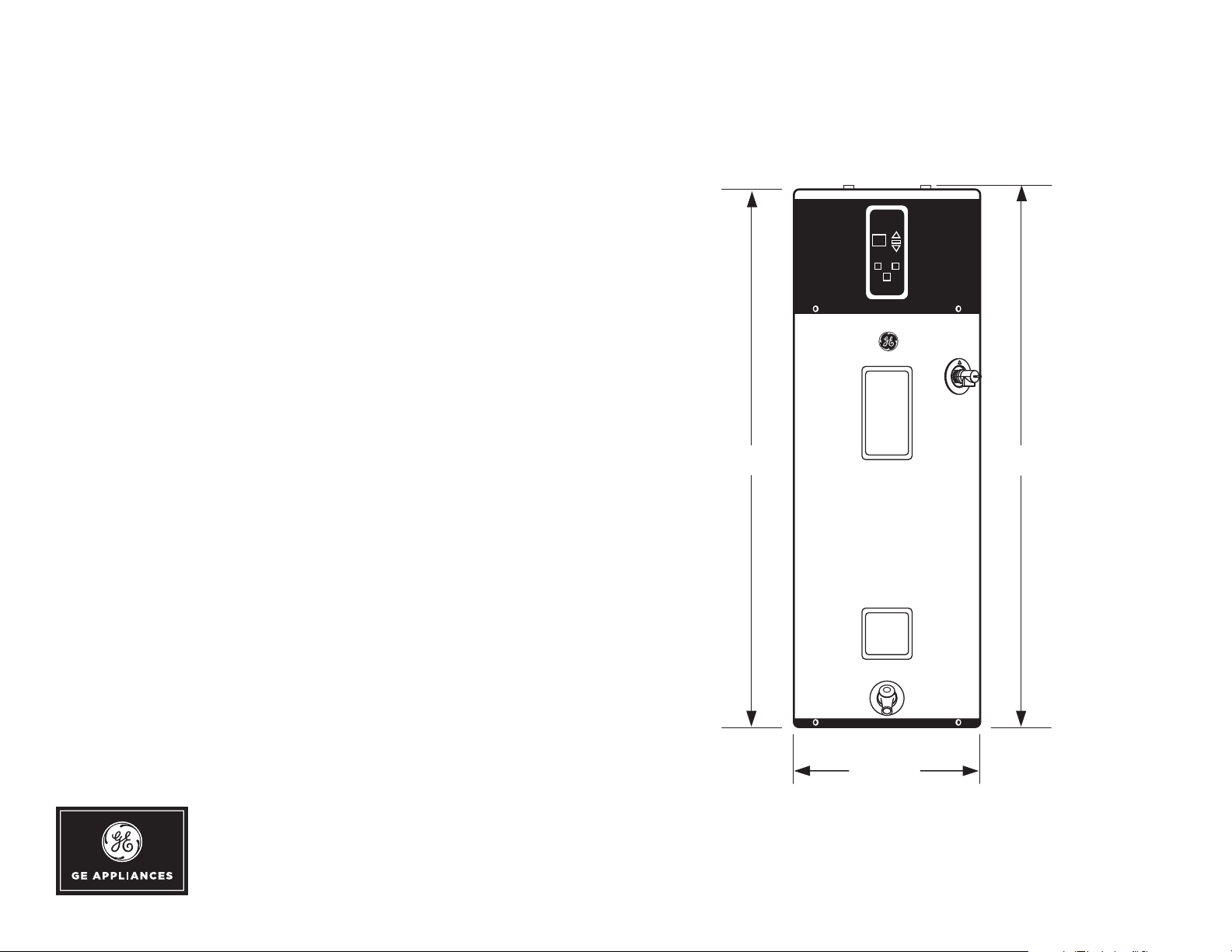
DIMENSIONS AND INSTALLATION INFORMATION (IN INCHES)
LOC A L IN STALLATION REGUL ATIONS: This water heater must be
installed in accordance with these instructions, local codes, utility codes,
utility company requirements or, in the absence of local codes, the latest
edition of the National Electrical Code. It is available from some local
libraries or can be purchased from the National Fire Prevention Association,
Batterymarch park, Quincy, MA 02169 as booklet ANSI/NFPA 70.
INSTALLATION I N FORMATI O N : For complete information, see installation
instructions packed with your water heater.
POWER REQUIREMENTS: Check the markings on the rating plate of the
water heater to be certain the power supply corresponds to the water heater
requirements.
LOC ATION : Locate the water heater in a clean dry area as near as practical
to the area of greatest heated water demand. Long uninsulated hot water lines
can waste energy and water.
NOTE: Because this unit draws in air from the room to heat the water, the
room must be at least 10’ x 10’ x 7’ (700 cubic feet) or larger. If the room is
smaller, there must be a louvered door. Louvers should be 240 square inches
(0.15m2) or greater. If two louvers are used, one should be near the top of
the door. Place the water heater in such a manner that the air filter, cover
and front panels can be removed to permit inspection and servicing, such
as removal of elements or cleaning of the filter. The water heater and water
lines should be protected from freezing temperatures and high-corrosive
atmospheres. Do not install the water heater in outdoor, unprotected areas.
GeoSpring
59-1/2" 60-3/4"
For answers to your Monogram, GE Café™ Series, GE Profile™ Series or
GE Appliances product questions, visit our website at geappliances.com
or call GE Answer Center® Service, 800.626.2000.
21-3/4"
Above illustration intended for dimensional reference only.
Refer to photograph for actual product appearance.
Specification Revised 3/17
Page 2
GEH50DEEDSC
GeoSpring™ Hybrid Electric Water Heater
DIMENSIONS AND INSTALLATION INFORMATION (IN INCHES)
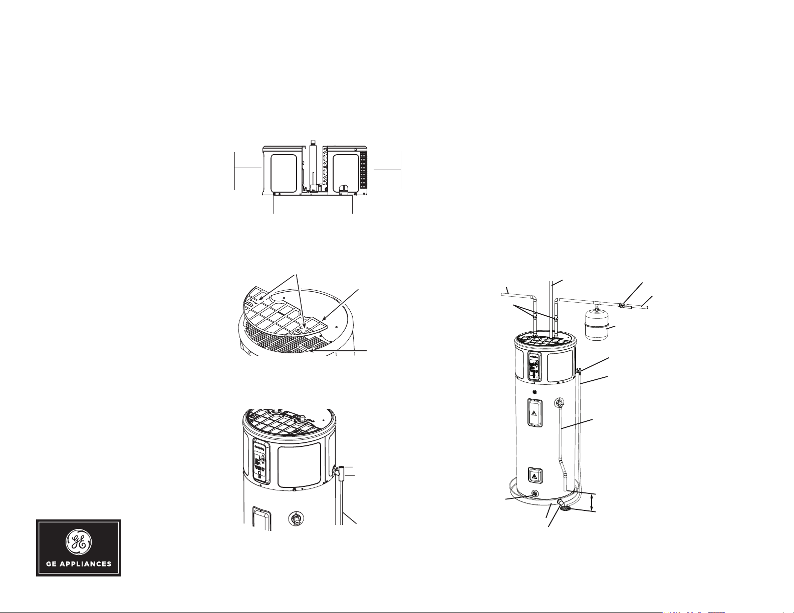
FRONT & BACK CLEARANCE
REQUIREMENTS: A 7" clearance is
recommended with a minimum of 5-1/2"
air space between any object and the
front and back of the water heater and
7" on each side. Clearance is needed to
allow for removal of the front and back
covers in the event service is needed.
TOP FILTER REMOVAL
CLEARANCE REQUIREMENTS:
A minimum 6" clearance is required at
the top of the water heater to pull the
filter up and remove it for cleaning. It
is critical that the hot and cold water
plumbing and the electrical connections
do not interfere with the removal of
the filter.
5-1/2”
(14 cm)
5-1/2”
(14 cm)
Tabs
Filter
Slots
WATER SUPPLY CONNECTIONS: Refer to the illustration below
for suggested typical installation. The installation of unions or
flexible copper connectors is recommended on the hot and cold water
connections so that the water heater may be easily disconnected for
servicing if necessary. The HOT and COLD water connections are clearly
marked and are 3/4" NPT on all models.
NOTE: Install a shut-off valve in the cold water line near the water
heater. This will enable easier service or maintenance of the unit later.
IMPORTANT: Do not apply heat to the HOT or COLD water
connections. If sweat connections are used, sweat tubing to adapter
before fitting the adapter to the cold water connections on heater.
Any heat applied to the hot or cold water connection will permanently
damage the dip tube.
Hot water
outlet to fixtures
Unions
To electrical junction
box (use only copper
conductors)
Thermal
expansion
tank
Barbed tee
Condensate
drain flexible
tube
Shut-off
To cold water
supply
CONDENSATE DRAIN REQUIRED:
A primary drain pipe must be installed at
the top right side of the water heater. The
primary drain is intended to carry all
condensate away.
Overflow
Main drain pipe
Direct the main
drain pipe into a
drain
Drain
Catch pan (If required)
Catch pan drain tube
Temperature & pressure
relief valve drain tube
Relief valve discharge
6” (15.2cm) minimum
from the floor
Above illustration intended for dimensional
reference only. Refer to photograph for
actual product appearance.
Specification Revised 3/17
Page 3

GEH50DEEDSC
GeoSpring™ Hybrid Electric Water Heater
VERIFICATION CHECKLIST:
1 TANK LOCATI O N :
- Is room size less than 10x10x7 (700 cu. ft.)? If yes, Louvered door or similar ventilation is needed.
- Back of unit away from wall by 7 inches.
- Front of unit is free and clear.
- Is the water heater level? If no, add shims under the base of the unit.
2 PLUMBING CONNECTIONS:
- Do not prevent air filter removal.
- No leaks after filling the tank with water, either when water is flowing or not.
3 CONDENSATE LINES ARE IN PLACE:
- Longer PVC pipe on lower drain nozzle and directed into a floor drain or a condensate pump.
4 T & P VALVE is working and drain line completed per local code.
5 ELECTRICAL CONNECTION does not prevent air filter removal.
6 Ver if y CONTROL PANEL displays 120°F (49°C) Hybrid Mode.
7 Veri f y FI LT E R is in place.
NORMAL STARTUP—WHAT TO EXPECT AFTER PRESSING THE POWER BUTTON
ELAPSED TIME HYBRID WATER HEATER ACTIONS COMMENTS
:00 to 2:00 minutes Unit will go through self-check This 2 minute off-time prevents compressor from being “short cycled"
(improved reliability).
2:00 to 10:00 minutes Compressor and fan turn on and run
for 8 minutes
10:00 to 30:00 minutes Compressor and fan turn off, heating elements
turn on for approximately 20 minutes.
30 minutes and beyond Upper element turns off, and compressor
turns back on.
NOTE: Heat pump operating range is 35°F to 120°F.
This 8 minute period is used to ensure tank is full of water (dry fire
prevention algorithm).
Quickly provides initial amount of hot water for user (~25 gallons).
Uses efficient heat pump for majority of heating.
Specification Revised 3/17
Page 4

GEH50DEEDSC
GeoSpring™ Hybrid Electric Water Heater
FEATURES AND BENEFITS
62% more efficient than a standard electric 50-gallon water heater
Saves the average household $365 every year* in water heating expenses - that’s $3,650
savings over a 10-year period
Provides the same amount of hot water as a traditional 50-gallon standard electric water
heater with 65 gallons first-hour delivery
Installs like a standard electric water heater with the same top water and electrical
connections, making replacing your old standard water heater quick and easy
Electronic controls with 4 operating modes plus a vacation setting make it simple to select the
temperature and optimal energy savings performance
Utilizes heat pump technology to absorb the heat in ambient air and transfers it into water,
making GeoSpring an efficient and environmentally friendly water heater
Qualifies for state and local utility rebates and tax credits
Designed for common indoor installation in areas such as: basement, garage, closet, utility
room, attic, etc.
Limited 10 year warranty provides peace of mind and dependability
GEH50DEEDSC - Charcoal
* Based on DOE test procedures and comparison of 50-gallon standard electric tank
water heaters using 4879 kWh per year vs. the GeoSpring hybrid water heater using
1830 kWh per year and national average electricity rate of 12 cents per kWh
GeoSpring
Specification Revised 3/17
 Loading...