

Page 1
GE Oil & Gas
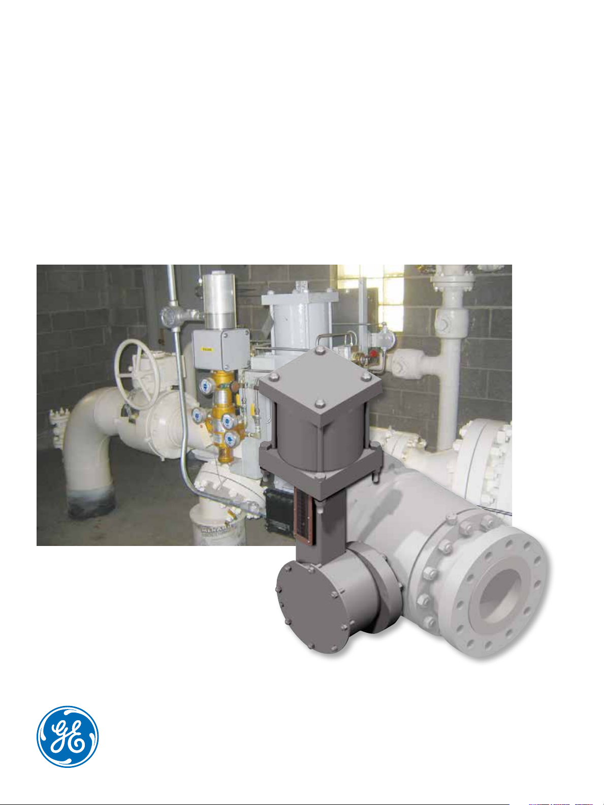
Becker* Rotary Piston Double
Acting (RPDA)
Heavy -duty, high performance applications
require RPDA Actuators
Page 2
2
Page 3
Becker RPDA Rotary Piston Double Acting
Actuators from GE Oil & Gas are ideally
suited for operations that demand a lock
last failure mode, including below ground
regulation and bleed-to-pressure
applications. These long-lasting, compact,
durable, and maintenance free actuators
can be retrofitted onto almost all pipeline
valves. RPDA Actuators are built to accept
high pressure power gas and can
incorporate options that eliminate
emissions and economically reduce
below-ground noise.
Features
Bleed to Pressure System* can
eliminate bleed gas emissions
Retrofits to almost any pipeline valve
High pressure RPDA actuator accepts
high pressure natural gas up to 500
psig (3447 kPa).
Upright actuator design saves space
and promotes longer actuator piston
seal life
Designed to be maintenance free
Comes equipped with a precision linear
scale that indicates valve position in ten
degree increments.
Crank-arm design actuators are
specifically suited for control valve
applications
May be mounted in any installation
orientation
3
Page 4
Technical Specifications
Actuator Mechanism Type
Rotation (Output)
Actuator Stops
Installation
Coating
Power Gas Requirements
Pneumatic crank arm
90° (standard)
Integral
Vertical (recommended),
Horizontal
Epoxy (standard)
Sweet natural gas
500 psig (3447 kPa) Models
Maximum Power Gas
10L and smaller 4
50 psig (3103 kPa) Models 12L
and larger
Minimum Power Gas
50 psig(345 kPa)
recommended
-20°F to +160°F (-29°C to
Operating Temperature
Range
+71°C) standard, -30°F to
+160°F (-34°C to +71°C)
(Optional low temp. spec.)
Torque Output
Dimensions
See Table 7
See Tables 3, 4, and 5
Filtered to 100μ nominal. Free
Sweet Natural Gas
Specification
of excessive moisture (< 7 lbs.
entrained H2O per 1.0 mmscf)
and liquid hydrocarbons.
If excessive moisture or hydrocarbon content is present, a
Filter-Dryer may be necessary. For adequate filtration and
elimination of moisture, a Becker Model FD-1500 Filter-Dryer
should be installed. Refer to Becker FD-1500 literature to
determine if a Model FD-1500 Filter-Dryer is necessary.
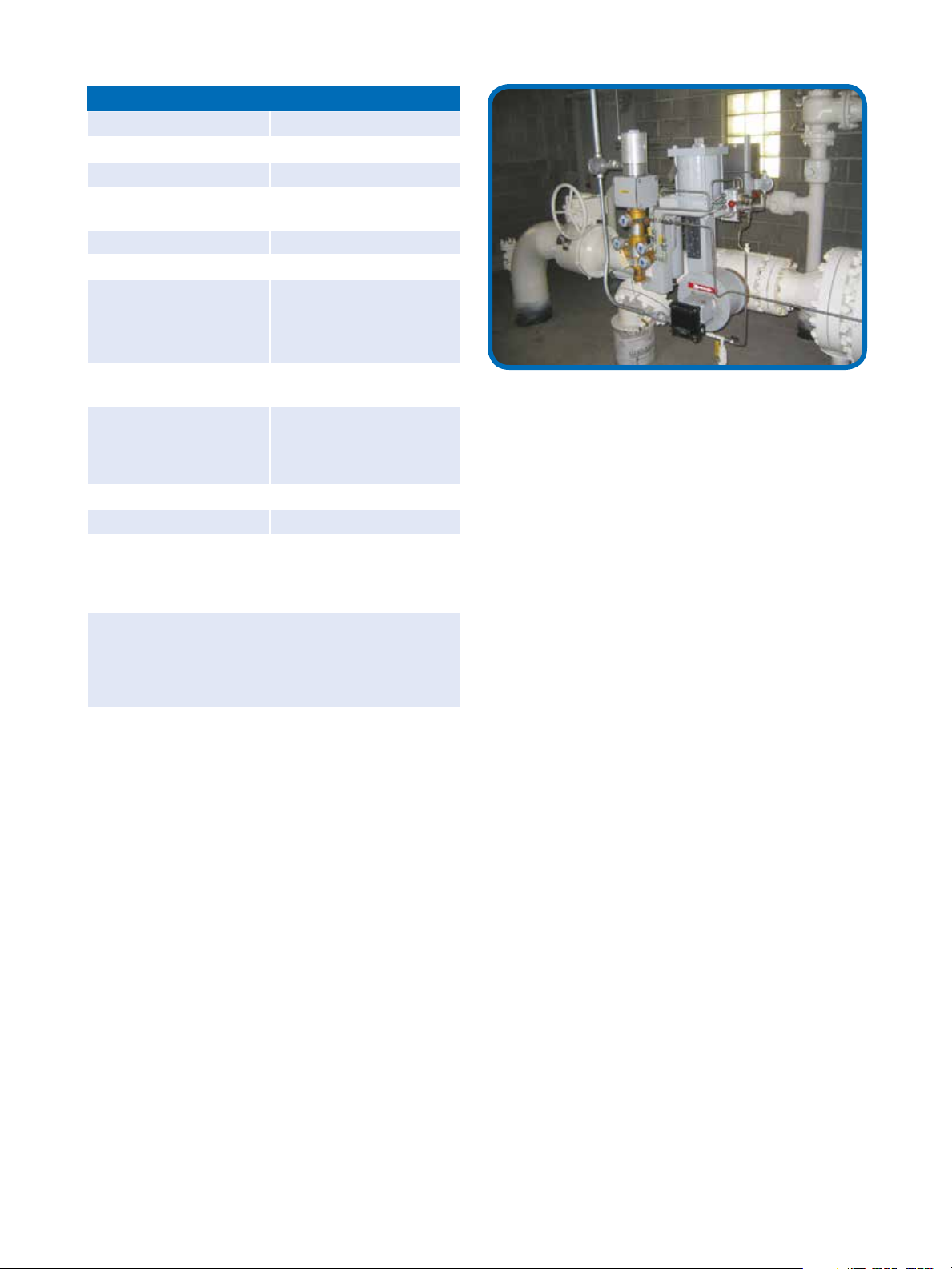
Figure 2 - Becker RPDA Actuated Control Valves
A pressure control regulator station is shown here with Becker RPDA
actuators and T-Ball Control Valves. The RPDA actuators are equipped
with Becker VRP-CH Valve Regulator Pilots (VRP). The VRP is capable
of providing extremely accurate pressure control with fast response
necessary for power plant type applications. Additionally, note that
the VRP-CH pressure control pilots are equipped with Model VB-250
Volume Boosters to increase stroking speed. The primary regulator is equipped with a QTCV-T2 Quiet Trim Control Valve to provide
decreased noise during operation. The monitor regulator is equipped
with a FPCV-T0 Full Port Control Valve that ensures bubble tight shutoff with class VI shutoff.
4
Page 5
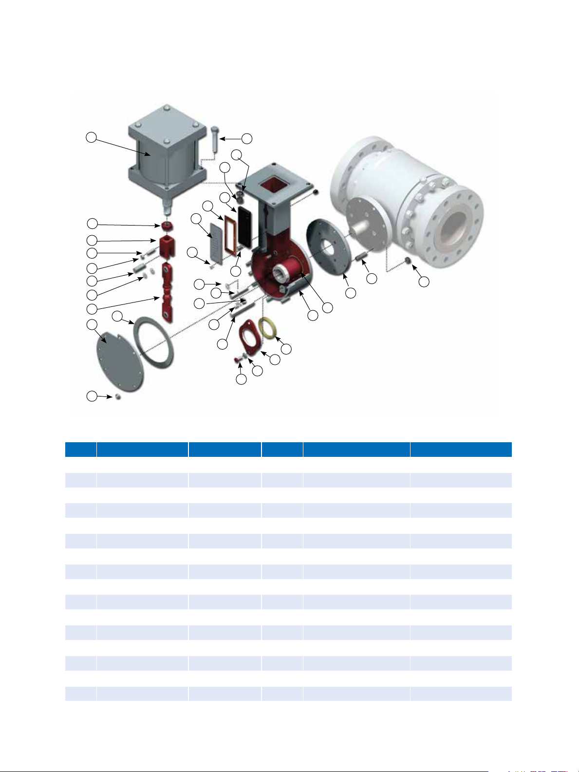
RPDA Rotary Piston Double Acting Actuator Components
1
16
2
3
4
5
6
7
8
9
10
11
17
18
20
21
22
23
12
13
14
15
19
30
29
24
25
28
27
26
32
31
33
Table 1 - RPDA Rotary Piston Double Acting Actuator parts description and materials
Item Description Material Item Description Material
1 Cylinder Carbon Steel 18 Indicator Screw Stainless Steel
2 Jam Nut Carbon Steel 19 Indicator Frame Screw Carbon or Stainless Steel
3 Rod Clevis Carbon Steel 20 Tru-Arc Ring Carbon Steel
4 Indicator Bar Stainless Steel 21 Torque Arm Pin Stress Proof Steel
5 Position Indicator Aluminum 22 Pin Clamp Carbon Steel
6 Rod Clevis Pin Stress Proof Steel 23 Pin Clamp Hardware Carbon Steel
7 Tru_Arc Ring Carbon Steel 24 Square Key Carbon Steel
8 Connecting Link Carbon Steel 25 Outboard Bearing Belt Carbon Steel
9 Cover Plate Gasket Rubber 26 Outboard Bearing Washer Carbon Steel
10 Cover Plate Carbon Steel 27 Outboard Bearing Plate Carbon Steel
11 Cover Plate Nut Carbon Steel 28 Outboard Bearing Duralon
®
12 Cylinder Bolt Carbon Steel 29 Actuatot Housing Carbon Steel
13 Cylinder Lockwasher Carbon Steel 30 Torque Arm Carbon Steel
14 Cylinder Nut Carbon Steel 31 Adapter Plate Carbon Steel
15 Indicator Frame PVC 32 Stud Carbon Steel
16 Indicator Gasket Rubber 33 Nut Carbon Steel
17 Lexan Cover Lexan 34 Vent Elbow Plastic
5
Page 6

Becker RPDA Rotary Piston Double Acting Actuator Cylinder Components
1
Table 2 - Components & Materials for construction of RPDA
2
3
4
5
8
9
10
11
12
13
14
5
6
7
Rotary Piston Double Acting Actuator Cylinder
Item Description Material
1 Hex Nut Steel
2 Cylinder Tie-Rod High Strength Steel
3 Piston Head (top) Steel
4 Tube Seal (top) Buna-N O-Ring
5 Piston U-Cup Seal (top) Buna-N
6 Rod Clevis Pin Stress Proof Steel
7 Piston Wear Strip Reinforeced Teflon
8 Piston Nodular Iron
9 Piston Rod Hard Chrome Plated Steel
10 Tube Steel (bottom) Buna-n O-RIng
11 Piston Head (bottom Steel
12 Piston Rod Seal Polyurethane
13 Piston Rod Bearing Duralon
14 Gland Plate Steel
15 Gland Plate Screws (SHCS) Alloy Steel
16 Piston Tube Alloy Steel
Teflon is a registered trademark of Dupont Company
Duralon is a registered trademark of Rexnord, Inc.
®
®
15
15
Figure 4 - RPDA Rotary Piston Double Acting Actuator Cylinder
Exploded View
RPDA Actuators Standard Mounting Configurations
FLOW
FLOW
Figure 5.1
Mount #1 - Left Hand (Standard)
with clean sweep feature
Actuator located on left hand
side of valve when looking in
directionof flow (actuator
vertical/valve stem horizontal).
Figure 5.2
Mount #2 - Right Hand
Actuator located on right hand
side of valve when looking in
direction of flow (actuator
verticle/valve stem horizontal).
FLOW
Figure 5.3
Mount #3 - Vertical Stem
(Actuator Downstream)
Actuator located on downstreamside of valve when looking in direction of flow (actuator
horizontal/valve stem vertical).
FLOW
Figure 5.4
Mount #4 - Vertical Stem
(Actuator Upstream)
Actuator located on up-stream
side of valve when looking in
direction of flow (actuator
horizontal/valve stem vertical).
6
Page 7

RPDA high pressure actuator built
solid for all your control valve needs
Bleed to Pressure System* Can Eliminate
Bleed Gas Emissions
GE’s Becker RPDA Actuators feature the unique ability
to incorporate the Bleed to Pressure System feature.
GE’s Becker RPDA Actuators and control instrumentation can accept high pressure power gas and discharge
bleed gas to lower pressure systems.Bleed to Pressure
Systemeliminates all atmospheric emissions!
Maintenance Free
The RPDA actuator is designed to be maintenance free,
no regular lubrication is required for the piston cylinder
or the actuator mechanism.
High Pressure Capability
The RPDA actuator is specifically
constructed to accept high
pressure natural gas up to
500 psig (3448 kPa). Higher
pressure power gas allows use
of smaller actuators and
implementation of Becker
products’ unique Bleed to
Pressure System.
Below Ground Actuator Option Reduces Noise
Attenuation up to 37 dBA
Becker RPDA actuators are available with a unique
below ground option that provides superior noise
attenuation in regulator stations at minimal cost.
Additionally, below ground stations minimize ambient
heat loss by maintaining piping systems below ground.
We can retrofit to almost any valve in
your pipeline
We can provide high quality actuators to mate to almost any quarter turn valve, regardless of manufacturer
or age. We have years of experience successfully adapting our actuators to fit a multitude of valves.
U-Cup Seals
U-cup Piston Seals are designed to provide superior
sealing capabilities with minimal friction. This design
allows accurate positioning of the control valve actuator
with very slight pressure differential to the piston.
Vertical Advantage
Upright actuator promotes
longer actuator piston seal life,
saves space, and requires less
maintenance than other actuators.
Easy to Read Travel Indicator
All RPDA actuators come equipped
with a precision linear scale that
indicates valve position in ten
percent increments.
Crank Arm Designed
for Control Valves
Crank arm design actuators are specifically
suited for control applications. The crank arm provides
an increasing torque curve that develops high torque
output where it counts. Additionally, the crank arm
design minimizes friction and lost motion.
Torque Arm Bearings
RPDA Actuators feature two large Torque Arm
Bearings to eliminate side load to control valve stem.
Both inboard and outboard torque arm bearings are
manufactured from non-metallic Duralon™ material to
ensure maximum load bearing capacity.
Duralon is a registered trademark of Rexnord, Inc.
Figure 6 - Cutaway view of RPDA Actuator and Cylinder.
Custom Coatings Available
Standard preparation of Becker RPDA actuators includes sandblast per SP-10 and epoxy coating for above
ground actuators and coal tar epoxy for below ground
actuator portions. RPDA actuators are available with
custom coatings to suit application needs
7
Page 8

E
A
C
B
D
G
F
I
Figure 7 - RPDA Single Cylinder Actuator up to 12 inch stroke
Table 3 - RPDA Single Cylinder Actuator Dimensions up to 12 inch stroke
H
Dimensions in inches (mm) Weight Volume
Model A B C D E F G H I
4D
5D
6D
6F
8F
8H
8L
10F
10H
10L
12L
14L
9.25
(235)
9.56
(243)
10.19
(259)
12.19
(310)
11.69
(297)
13.06
(332)
17.69
(449)
13.06
(332)
15.06
(383)
19.06
(484)
19.06
(484)
20.94
(532)
14.13
(359)
14.13
(359)
14.63
(371)
18.19
(462)
18.81
(478)
19.81
(503)
25.06
(637)
19.25
(489)
20.25
(514)
25.50
(648)
25.50
(648)
25.75
(654)
28.63
(727)
28.94
(735)
30.06
(764)
34.81
(884)
36.50
(927)
36.75
(933)
51.50
(1308)
38.56
(979)
42.44
(1078
53.31
(1354)
53.81
(1367)
55.56
(1411)
2.38
(60)
2.38
(60)
2.38
(60)
3.63
(92)
3.63
(92)
4.75
(121)
7.25
(184)
3.63
(92)
4.75
(121)
7.25
(184)
7.25
(184)
7.25
(184)
6.25
(159)
7.63
(194)
8.63
(219)
6.50
(165)
8.50
(216)
8.50
(216)
8.50
(216)
10.63
(270)
10.63
(270)
10.63
(270)
12.75
(324)
14.75
(375)
4.50
(114)
5.50
(140)
6.50
(165)
6.50
(165)
8.50
(216)
8.50
(216)
8.50
(216)
10.63
(270)
10.63
(270)
10.63
(270)
14.75
(375)
14.75
(375)
0.38
(10)
0.38
(10)
0.38
(10)
1.38
(35)
1.38
(35)
1.50
(38)
4.00
(102)
1.38
(35)
1.50
(38)
4.00
(102)
4.00
(102)
4.00
(102)
5.38
(137)
5.38
(137)
5.38
(137)
7.00
(178)
7.00
(178)
7.00
(178)
8.50
(216)
7.00
(178)
7.00
(178)
8.50
(216)
8.63
(219)
8.63
(219)
NOTE: Dimensions “B” and “C” will change for below ground units according to depth of burial
2.13
(54)
2.13
(54)
2.13
(54)
2.75
(70)
2.75
(70)
2.75
(70)
3.50
(89)
2.75
(70)
2.75
(70)
3.50
(89)
3.63
(92)
3.63
(92)
lbs
(kg)
120.00
(54)
125.00
(57)
150.00
(68)
210.00
(95)
245.00
(111)
295.00
(134)
440.00
(200)
345.00
(157)
390.0
(177)
545.00
(247)
655.00
(297)
850.00
(386)
3
in
(cm3)
50.2
(823)
78.5
(1,286)
113.0
(1,852)
169.6
(2,779)
301.4
(4,940)
401.9
(6,576)
602.9
(9,879)
471.0
(7,718)
628.0
(10,291)
942.0
(15,437)
1846.3
930,256)
1846.3
(30,256)
8
Page 9

E
A
C
C
B
K
G
D
F
J
I
Figure 8 - RPDA Single Cylinder Actuator greater than 12 inch stroke
Table 4 - RPDA Single Cylinder Actuator Dimensions greater than 12 inch stroke
H
Dimensions in inches (mm) Weight Volume
Model A B C D E F G H I J K L
12T
12X
12Z
14T
14X
14Z
29.56
(751)
33.56
(852)
35.56
(903)
30.94
(786)
34.94
(887)
36.94
(938)
41.00
(1041)
47.63
(1210)
48.63
(1235)
41.63
91057)
48.00
(1219)
49.00
(1245)
86.56
(2199)
100.38
(2550)
103.38
(2626)
88.31
(2243)
101.94
(2589)
104.94
(2665)
12.00
(305)
14.50
(368)
15.75
(400)
12.00
(305)
14.50
(368)
15.75
(400)
12.75
(324)
12.75
(324)
12.75
(324)
14.75
(375)
14.75
(375)
14.75
(375)
12.75
(324)
12.75
(324)
12.75
(324)
14.75
(375)
14.75
(375)
14.75
(375)
3.63
(92)
3.63
(92)
3.63
(92)
3.63
(92)
3.63
(92)
3.63
(92)
12.00
(3050
12.00
(305)
12.00
(305)
12.00
(305)
12.00
(305)
12.00
(305)
5.00
(127)
5.00
(127)
5.00
(127)
5.00
(127)
5.00
(127)
5.00
(127)
3.75
(95)
3.75
(95)
3.75
(95)
3.75
(95)
3.75
(95)
3.75
(95)
20.00
(508)
20.00
(508)
20.00
(508)
20.00
(508)
20.00
(508)
20.00
(508)
NOTE: Dimensions “B” and “C” and K” will change for below ground units according to depth of burial
9.56
(243)
9.56
(243)
9.56
(243)
9.56
(243)
9.56
(243)
9.56
(243)
lbs
(kg)
985
(447)
1135
(515)
1295
(588)
1165
(529)
1335
(606)
1425
(647)
3
in
(cm3)
2262.0
(37,068)
2715.0
(44,491)
2941.0
(48.194)
3079.0
(50,456)
3695.0
(60,550)
4003.0
(65,597)
9
Page 10

E F
A
L
C
K
G
D
Figure 9 - RPDA Double Cylinder Actuator Dimensions greater than 12 inch stroke
Table 5 - RPDA Double Cylinder Actuator Dimensions greater than 12 inch stroke
B
J
I
H
Dimensions in inches (mm) Weight Volume
Model A B C D E F G H I J K L
D12T
D12X
D12Z
D14T
D14X
D14Z
29.56
(751)
33.56
(852)
35.56
(903)
30.94
(786)
34.94
(887)
36.94
(938)
41.00
(1041)
47.63
(1210)
48.63
(1235)
41.63
91057)
48.00
(1219)
49.00
(1245)
86.56
(2199)
102.19
(2550)
106.19
(2697)
91.31
(2319)
103.94
(2589)
107.94
(2742)
12.00
(305)
14.50
(368)
15.75
(400)
12.00
(305)
14.50
(368)
15.75
(400)
12.75
(324)
12.75
(324)
12.75
(324)
14.75
(375)
14.75
(375)
14.75
(375)
12.75
(324)
12.75
(324)
12.75
(324)
14.75
(375)
14.75
(375)
14.75
(375)
3.63
(92)
3.63
(92)
3.63
(92)
3.63
(92)
3.63
(92)
3.63
(92)
12.00
(3050
12.00
(305)
12.00
(305)
12.00
(305)
12.00
(305)
12.00
(305)
5.00
(127)
5.00
(127)
5.00
(127)
5.00
(127)
5.00
(127)
5.00
(127)
3.75
(95)
3.75
(95)
3.75
(95)
3.75
(95)
3.75
(95)
3.75
(95)
20.00
(508)
20.00
(508)
20.00
(508)
20.00
(508)
20.00
(508)
20.00
(508)
NOTE: Dimensions “B” and “C” and K” will change for below ground units according to depth of burial
9.56
(243)
9.56
(243)
9.56
(243)
9.56
(243)
9.56
(243)
9.56
(243)
lbs
(kg)
2097
(952)
2375
(1078)
2565
(1165)
2110
(958)
2380
(1081)
2580
(1171)
3
in
(cm3)
4524
(74,135)
54300
(88,982)
5882.0
(96,389)
6158.0
(100,912)
7390.0
(121,100)
8006.0
(131,195)
10
Page 11

Table 6 - Becker RPDA Actuator Selection Table
T-Ball
Valve Size
500 (3447 kPa) = ΔP 1000 (6895 kPa) = ΔP 1500 (10342 kPa) = ΔP
Double Acting Double Acting Double Acting
2” (50 mm) 5D 5D 5D
3” (80 mm) 5D 5D 6D
4” (100 mm) 6F 6F 6F
6” (150 mm) 8F 8F 8H
8” (200 mm) 10F 10F 10H
10” (250 mm) 10H 10H 10L
12” (300 mm) 10L 10L 12L
Temperature -20° F (-28.9° C) 100 psig (689 kPa) Power Gas
Choose the Perfect Rotary Control
Valve for your Application
FPCV-T0 Series Full Port Control Valve:
High turndown capability up 100:1
High pressure drop shutoff capability to
Class VI
T-Ball
Valve Size
500 (3447 kPa) = ΔP 1000 (6895 kPa) = ΔP 1500 (10342 kPa) = ΔP
Double Acting Double Acting Double Acting
2” (50 mm) 5D 5D 5D
3” (80 mm) 5D 5D 6D
4” (100 mm) 6F 6F 6F
6” (150 mm) 8F 8F 8H
8” (200 mm) 10F 10F 10H
10” (250 mm) 10H 10H 10L
12” (300 mm) 10L 10L 12L
Temperature -20° F (-6.7° C) 100 psig (689 kPa) Power Gas
T-Ball
Valve Size
500 (3447 kPa) = ΔP 1000 (6895 kPa) = ΔP 1500 (10342 kPa) = ΔP
Double Acting Double Acting Double Acting
2” (50 mm) 5D 5D 5D
3” (80 mm) 5D 5D 6D
4” (100 mm) 6F 6F 6F
6” (150 mm) 8F 8F 8H
8” (200 mm) 10F 10F 10H
10” (250 mm) 10H 10H 10L
12” (300 mm) 10L 10L 12L
Temperature -20° F (-28.9° C) 125 psig (861 kPa) Power Gas
QTCV-T1 Series Quiet Trim Control Valve:
Noise attenuation up to 7 dBA
High turndown capability up to 200:1
High pressure drop shutoff capability to
Class V
QTCV-T2 Series Quiet Trim Control Valve:
Noise attenuation up to 17 dBA
High turndown capability up to 300:1
High pressure drop shutoff capability
to Class IV
T-Ball
Valve Size
500 (3447 kPa) = ΔP 1000 (6895 kPa) = ΔP 1500 (10342 kPa) = ΔP
Double Acting Double Acting Double Acting
2” (50 mm) 5D 5D 5D
3” (80 mm) 5D 5D 6D
4” (100 mm) 6F 6F 6F
6” (150 mm) 8F 8F 8H
8” (200 mm) 10F 10F 10H
10” (250 mm) 10H 10H 10L
12” (300 mm) 10L 10L 12L
Temperature -20° F (-6.7° C) 125 psig (861 kPa) Power Gas
1. Contact GE representative for valve sizes over 12” bore.
2. T-Ball valves are comprised of the following: FPCV-TO, FPBV, QTCV-T1, QTCV-T2, and QTCV-T4
3. For power gas pressures greater/less than 100 psig (689 kPa) contact GE.
4. For higher ΔP applications contact GE representative.
5. Power Gas = P
supply
- P
for applications that utilize Bleed to Pressure System™ Feature.
discharge
QTCV-T4 Series Quiet Trim Control Valve:
Noise attenuation up to 25 dBA
High turndown capability up to 200:1
High pressure drop shutoff capability to
Class IV
11
Page 12

Table 7 - Becker RPDA Actuator Output Torque Table
RPDA Actuator
Model Number
5D
6F
8F
8H
10F
10H
10L
12L
14L
12T
12X
14T
14X
14Z
D12T
D12X
D12Z
D14T
D14X
D14Z
NOTES:
1. See graph to right.
2. Power Gas = Psupply when discharge (vent to atmosphere).
3. Power Gas = Psupply- Pdischarge when utilizing Bleed to Pressure System™ feature.
4. Consult Becker when Psupply > 150psig to ensure satisfactory operation
12
Angular
Position
1
100 psig (689 kPa) 125 psig (862 kPa) 150 psig (1034 kPa)
RDPA Actuator Output Torque/ Power Gas
Ending 3600 in-lb (24821 n-m) 4500 in-lb (31026 n-m) 5400 in-lb (37232 n-m) 500 psig
Running 5334 in-lb (36777 n-m) 6669 in-lb (45978 n-m) 8002 in-lb (55173 n-m)
Ending 7557 in-lb (52104 n-m) 9446 in-lb (65128 n-m) 11336 in-lb (78159 n-m) 500 psig
Running 11377 in-lb (78442 n-m) 14221 in-lb (98050 n-m) 17066 in-lb (117668 n-m)
Ending 13761 in-lb (94879 n-m) 17201 in-lb (118597 n-m) 20642 in-lb (142322 n-m) 500 psig
Running 20717 in-lb (142839 n-m) 25896 in-lb (178547 n-m) 31076 in-lb (214264 n-m)
Ending 18117 in-lb (124912 n-m) 22646 in-lb (156139 n-m) 27176 in-lb (187372 n-m) 500 psig
Running 26253 in-lb (181009 n-m) 32816 in-lb (226259 n-m) 39380 in-lb (271519 n-m)
Ending 21477 in-lb (148079 n-m) 26846 in-lb (185097 n-m) 32216 in-lb (222121 n-m) 500 psig
Running 32334 in-lb (222932 n-m) 40417 in-lb (278662 n-m) 48501 in-lb (334403 n-m)
Ending 28277 in-lb (194963 n-m) 35346 in-lb (243702 n-m) 42416 in-lb (292448 n-m) 500 psig
Running 40976 in-lb (282519 n-m) 51220 in-lb (353146 n-m) 61465 in-lb (423783 n-m)
Ending 41501 in-lb (286139 n-m) 51876 in-lb (357672 n-m) 62252 in-lb (429212 n-m) 500 psig
Running 61222 in-lb (422109 n-m) 76527 in-lb (527634 n-m) 91833 in-lb (633169 n-m)
Ending 58760 in-lb (405136 n-m) 73450 in-lb (506420 n-m) 88140 in-lb (607704 n-m) 400 psig
Running 93781 in-lb (646595 n-m) 117226 in-lb (808244 n-m) 140671 in-lb (969893 n-m)
Ending 79642 in-lb (549112 n-m) 99553 in-lb (686394 n-m) 119463 in-lb (823668 n-m) 400 psig
Running 127108 in-lb (876381 n-m) 158886 in-lb (1095481 n-m) 190662 in-lb (1314571 n-m)
Ending 100412 in-lb (692316 n-m) 125515 in-lb (865395 n-m) 150618 in-lb (1038475 n-m) 400 psig
Running 156116 in-lb (1076381 n-m) 195145 in-lb (1345476 n-m) 234174 in-lb (1614571 n-m)
Ending 120017 in-lb (827488 n-m) 150021 in-lb (1034358 n-m) 180026 in-lb (1241236 n-m) 400 psig
Running 187277 in-lb (1291230 n-m) 234096 in-lb (1614035 n-m) 280916 in-lb (1936851 n-m)
Ending 136093 in-lb (938328 n-m) 170116 in-lb (1172908 n-m) 204140 in-lb (1407496 n-m) 400 psig
Running 211591 in-lb (1458868 n-m) 264488 in-lb (1823582 n-m) 317387 in-lb (2188307 n-m)
Ending 162665 in-lb (1121536 n-m) 203331 in-lb (1401918 n-m) 243998 in-lb (1682307 n-m) 400 psig
Running 253826 in-lb (1750068 n-m) 317282 in-lb (2187583 n-m) 380740 in-lb (2625108 n-m)
Ending 174886 in-lb (1205796 n-m) 218608 in-lb (1507249 n-m) 262329 in-lb (1808695 n-m) 400 psig
Running 275168 in-lb (1897216 n-m) 343961 in-lb (2371525 n-m) 412752 in-lb (2845824 n-m)
Ending 200824 in-lb (1384633 n-m) 251030 in-lb (1730791 n-m) 301236 in-lb (2076949 n-m) 400 psig
Running 312232 in-lb (2152761 n-m) 390290 in-lb (2690951 n-m) 468347 in-lb (3229142 n-m)
Ending 240034 in-lb (1654976 n-m) 300043 in-lb (2068724 n-m) 360051 in-lb (2482464 n-m) 400 psig
Running 374554 in-lb (2582460 n-m) 468194 in-lb (3228081 n-m) 561831 in-lb (3873690 n-m)
Ending 258066 in-lb (1779302 n-m) 322583 in-lb (2224131 n-m) 387099 in-lb (2668954 n-m) 400 psig
Running 406044 in-lb (2799577 n-m) 507556 in-lb (3499477 n-m) 609067 in-lb (4199366 n-m)
Ending 272187 in-lb (1876663 n-m) 340234 in-lb (2345831 n-m) 408281 in-lb (2814998 n-m) 400 psig
Running 423183 in-lb (2917747 n-m) 528980 in-lb (3647186 n-m) 634776 in-lb (4376626 n-m)
Ending 325331 in-lb (2243078 n-m) 406664 in-lb (2803849 n-m) 487997 in-lb (3364621 n-m) 400 psig
Running 507653 in-lb (3500147 n-m) 634567 in-lb (4375187 n-m) 761481 in-lb (5250226 n-m)
Ending 349772 in-lb (2411593 n-m) 437215 in-lb (3014491 n-m) 524658 in-lb (3617389 n-m) 400 psig
Running 550336 in-lb (3794431 n-m) 687920 in-lb (4743039 n-m) 825504 in-lb (5691647 n-m)
(3447) kPa
(3447) kPa
(3447) kPa
(3447) kPa
(3447) kPa
(3447) kPa
(3447) kPa
(2758 kPa)
(2758 kPa)
(2758 kPa)
(2758 kPa)
(2758 kPa)
(2758 kPa)
(2758 kPa)
(2758 kPa)
(2758 kPa)
(2758 kPa)
(2758 kPa)
(2758 kPa)
(2758 kPa)
Running
Ending
Torque Output
0° 45° 90°
Actuator Position (Degrees Travel)
MAOP
3
Page 13

Below Ground Regulator Options Additional Noise Attenuation
40
Noise Attenuation (dBa)
Below Ground Depth (ft.)
The Becker Below Ground Ball Valve Regulator option
is unique to GE and provides a multitude of benefits by
direct burial of the control valve. The valve actuator,
lubrication lines,and drain lines are extended above
ground while the ball valve remains below ground. The
primary advantage of Becker Below Ground Regulators
is inexpensive noise attenuation in excess of 25 dBA.
More than 25 dBA noise attenuation
Less ambient heat loss
May use smaller adjacent piping diameter
Smaller station footprint
Most economical noise attenuation
May eliminate need for buildings/enclosures by
utilizing the fiberglass cabinet
35 dBa
37 dBa
30
30 dBa
25 dBa
20
10
3 ft Depth
4 ft Depth
5 ft Depth
6 ft Depth
0
Figure 10 - Below Ground Noise Attenuation Compared to Depth.
Typical below ground depths range from 3 feet to 6 feet burial.
The below ground depth is measured from centerline of pipe to
ground. Below ground usually provides from 25 dBA to 37 dBA noise
attenuation
Figure 12 - Installation of Becker Below Ground Regulators
(After Backfill)
The customer was able to achieve up to 25 dBA noise attenua-
tion over conventional above ground control valves with minimal
costs. The RPDA actuator utilizes an extended linkage to throttle the
control valve below ground. Many GE customers have utilized the
below ground concept for many years with great success and minimal maintenance. The topworks of the control valve actuators are
enclosed with Becker CAB Series Fiberglass Cabinets (green) after
backfill of regulator station. 16” Below Ground Ball Valve Regulators
are located at left, while 30” Below Ground Ball Valve Regulators
are located at right. A masonry wall has been installed at the
perimeter of the station. Upstream station isolation valves are
located in the foreground of the picture.
Figure 11 - Installation of Becker Below Ground Regulators
(Prior to Backfill) A large natural gas transmission/distribution
company based in Southern California installed Becker Below
Ground Ball Valve Regulators to achieve maximum noise attenuation, minimal maintenance, and optimum cost effectiveness. The
Below Ground Regulator can provide up to 37 dBA additional noise
attenuation with minimal additional cost. Two different size Below
Ground Ball Valve Regulators are show here. 16” Bore Below Ground
Regulators are shown in background, while 30” bore Below Ground
Ball Valve Regulators are shown in foreground. The Below Ground
Ball Valve Regulators are shown during installation, prior to backfill
of the regulator station.
13
Page 14

Accessories
GE’s Becker Control Valve Actuators provide reliability and accuracy for all of your
control valve applications
Limit Switches
Limit switches provide an indication of valve status and are commonly utilized on both on-off
and control valves. A limit switch assembly will close a contact at both the full-open and at
the full-closed position of valve travel. The switches provide a remote indication to gas control,
RTU or a flow computer as to the status of a valve. Limit switch assemblies are available with a
variety of configurations.
Housing NEMA 4, 4X, 7, Class I, Groups C & D,
Division 1 & 2
Switches 2 or 4
Option 2 or 4 Hermetically Seales Switches
Position Transmitter
The Valve Position Feedback assembly provides a quantitative indication of the exact position
of a control valve. The Valve Position Feedback assembly provides 4-20 mA analog remote position feedback proportional to the control valve position. The feedback signal may be utilized
as an integral portion of the control loop or merely as an additional feedback signal to gas
control for monitoring valve status. Valve Position Feedback is typically utilized on flow control
valves
Transmitter 4-20 mA Output
Housing NEMA 4, 4X, 7, Class I, Groups C & D,
Division 1 & 2
Switches 2 or 4
Option 2 or 4 Hermetically Seales Switches
SPDT Single Pole, Double Throw
DPDT Double Pole, Double Throw
up to 125 V D.C. at .5 amps
up to 250 V A.C. at 15 amps
SPDT Single Pole, Double Throw
DPDT Double Pole, Double Throw
up to 125 V D.C. at .5 amps
up to 250 V A.C. at 15 amps
Trip Valve
The Trip Valve protects double-acting actuators from loss of supply gas pressure. In the event
that the supply gas pressure falls below a minimum level, the trip valve can be configured to do
one of the following: lock the valve in last position, stroke the valve to the full-open position*,
Stroke the valve to the full-closed position*
*These applications require an additional volume tank to perform the operation
Max Allowable 150 psig 91034 kPa)
Weight 4.5 lbs (2.0 kg)
Body Connections 1/4” FNPT
Temp. Limits -40°F to + 180 F
(-40°C to +82°C)
Hydraulic Operator override
The Hydraulic pump override is utilized for manual operation of large control valves when
pneumatic power is not available. The Hydraulic pump override utilizes a hydraulic pump and
reservoir to develop necessary torque to close/open the control valve. Hydraulic pump overrides are typically utilized on ball control valves larger than 16” bore.
Trip Point Adjustable from 40 psig (276 kPa)
to 70% of supply pressure
Volume Tank Required for fail-open or fail closed modes. DOT approval
LP Tank (240 psig (1655 kPa) Max
with DOT Stamp). Size based on
application
14
Page 15

Let GE help select the perfect rotary control valve actuator
Table 8- Selection table for Becker Control Valves and Actuators
RPDA (Small Models)
RPDA (Large Models)
SYDA (Small Models)
SYDA (Large Models)
RPSR
SYSR
LPDA (Small Models)
LPDA (Large Models
LPSR
LD
Actuator Instrumentation
VRP-CH-Pilot
VRP-B-CH Pilot
VRP-SB-CH-Pilot
VRP-SB-PID Pilot
HPP-4 Positioner
HPP-5 Positioner
HPP-SB Positioner
DNGP Positioner
VRP-SB-GAP
FPCV-T0
QTCV-T1
QTCV-T2
QTCV-T4
Globe Series
Bleed to Pressure System BPS
AB Series Atmospheric Bleed
Control
NBV Series No-Bleed Valve
DPS-2 Series Non-Bleed Sensor
PS-2 Series Non-Bleed Sensor
SP Series Setpoint Pump
RSM Series Remote Setpoint Module
Panel Mounting
Stainless Steel Option
VB Series Volume Booster
QEV Series Quick Exhaust Valve
I/P Transducer
SLV Series Signal Lock Valve
™
• • • • • •
• •
• • • •
• • • •
• • • • • •
• • •
• • • •
• • • • • • • • • •
• • • • • • • • • •
Compatible Valves
• • • • • •
• • • • • •
• • • • • •
• • • • • •
• • •
Actuator Options
• • • • • • •
• • • • • • •
• • • •
• • • •
• •
• • • • •
• • • • •
• • • • • •
• • • • • • • •
• • • • •
• •
• • •
• • •
GE has a wide variety of control valve
actuators with a variety of features that
ensure the optimum solution for your
application needs. Refer to the figures
to the left to assist you in selecting the
proper control valve actuator and
accessories.
Figure 13 - Becker RPDA Rotary Piston Double Acting
Actuator
The Becker RPDA Actuator is a rugged, quarter-turn
actuator design for the rigors of aggressive throttling
service. The RPDA features a high pressure crank-arm
design specifically geared for control valve service.
The high pressure capability of the RPDA allow power
gas pressures up to 500 psig. This extended power
gas range permits the implementation of GE’s unique
“bleed to pressure system” that eliminates all atmospheric emissions. Additionally, the RPDA is available
with a Below Ground Option to substantially reduce
noise with minimal additional expense.
1. RPSR, SYDA, and LPDA Small Models are defined as actuator size <2000 in³ (0.333m³).
2. RPSR, SYDA, and LPDA Large Models are defined as actuator size >2000 in³ (0.333m³).
3. LD Series Actuators are limited to Becker Series Globe Valves
TM
is limited to discharge pressure systems below 300 psig (2068 kPa). Consult Becker for
4. BPS
application assistance.
*CAUTION: This information is intended as a guideline for application
of Becker Control Valve products. GE strongly recommends consulting
Becker product Engineering prior to application of any product.
15
Page 16

GE Oil & Gas
16250 Port Northwest
Houston TX 77041
+1 866 754 3562
www.geoilandgas.com
*Denotes trademakr of General Electric Company.
© 2014 Genera l Electric Com pany. All Rights Res erved.
GEA19651 09/2014
 Loading...