

Page 1
GE Energy
®
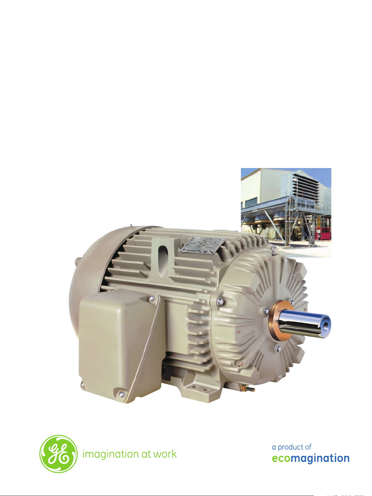
X$D Ultra
Heat Exchanger Motors
5-75 HP
460 Volt
661
Page 2

Experience, Safety and Quality
We’ve manufactured motors for over 125 years.
In 1879, GE founder, Thomas Edison constructed the first electric
motor ever made for a 110 to 120 Volt line at Menlo Park, NJ. This
device still exists and is operative! It is located in the Edison Historical
Collection in New Jersey.
We continue to innovate manufacturing.
Leading the way in six sigma and lean manufacturing processes helps
to ensure that GE can deliver the best value in its product.
X$D Ultra® 661 meets and exceeds
user expectations.
Safety
•
The X$D Ultra® 661 incorporates four-point lifting lugs which are
integrally cast into the motor frame. This allows the user to pick up the
motor vertically using all four points instead of a single eyebolt.
Improved Customer Operating Performance
•
The X$D Ultra® 661 meets or exceeds API-661 and IEEE-841
Standards. It includes advanced features such as a superior insulation
and bearing system and a performance test report for each motor—all
backed by a five year warranty. The X$D Ultra® 661 is one of the most
durable and reliable motors you can buy.
Improved Customer Environmental Performance
•
Replacing one 75 HP, 1800 RPM Pre-EPAct motor (rewound once)
with GE’s X$D Ultra® 661 could save enough energy to power two US
households for more than one year.
• If a US Industrial user replaced one 75 HP, 1800 RPM Pre-EPAct
motor with an X$D Ultra®, greenhouse gas emissions could be
reduced by as much as 12 metric tons per year.
Built to the highest Standards and Certifications
• Rated for IP-55 protection.
• NEMA, UL, CSA, IEEE-45, IEEE-841, API-661.
Page 3

Powerful Features
3
Superior Electrical
Performance
The X$D Ultra® 661 meets or exceeds
NEMA Premium® Nominal efficiencies
and exceeds all NEMA Premium®
minimum guaranteed efficiencies
1 GEGARD2400™ insulation systems
feature Class H insulation materials
and 1.15 service factor. This system
increases motor protection against
IGBT drive voltage spikes up to
2,400 volts @ 0.1 microsecond rise
time, which exceeds NEMA MG1-31
standards. It is also capable of an
Infinite:1 variable torque speed range.
2 Meets NEMA design B torque and
current requirements.
3 A five-year warranty comes standard
with every X$D Ultra® 661 motor.
(60 months operational/66 months
maximum from shipment).
11
14
15
Bearings
GE’s bearing system assures the
maximum possible bearing life when
combined with a maintenance program.
4
Overall displacement is 0.0004 inches
peak-to-peak. Rotor assembly balanced
to ISO 1940 Grade 1.0. This helps to
extend the life of the motor and the
connected equipment.
5
A non-contact labryinth seal is
integrated to both the drive-end and
opposite drive-end ensuring IP55
protection of the bearing system.
6 Fully charged lubrication system with
a temperature-resistant polyurea
grease suitable for a wide temperature
range (-40°C to +130°C).
7 An oversized roller bearing has
been designed to yield 40,000 hours
minimum L10 bearing life for belted
loads.
8
A cast-iron gasketed bearing inner
cap is secured by a bolt with a
copper washer to ensure a totally
enclosed system. This helps to retain
lubricant and protects the bearing
system and interior of the motor from
contaminants.
9
Low temperature rise designs (15%
cooler on average than IEEE 841-2009
specification).
16
12
1
6
2
7
5
4
8
9
13
Proven Reliability
For years severe duty motors from GE
have proven their performance and
reliability in the most demanding process
industry environments.
10 Cast-in vibration pads provide
mounting locations for a minimum of
three axial and three radial probes.
11 Rugged cast iron frame, conduit box,
endshields and fan cover.
12
RTV sealed frame-to-endshield rabbet
fit.
13 Stainless steel T-drain at the lowest
point in bottom endshield and brass
plug on upper endshield helps to
relieve and prevent condensation.
Safety
GE has added features which make
this product safe to install, operate and
maintain.
14
Safer lifting is possible with a fourpoint, cast-in lifting system versus a
single eyebolt.
15 A silicon bronze box lug ground
terminal is located in the conduit box.
An additional ground terminal post
is located on the drive-end endshield
for greater operational safety.
16
Maximum surface temperature of
200°C stamped on auxiliary nameplate.
Qualified for Division 2 applications.
Optional CSA certification for Division 2
applications is also available.
10
Page 4

Selection Guide
Stocked as W8 (shaft up) and field-modifiable to W6 (shaft down) except where noted.
HP RPM Volts Frame FLA
5 1800 460 184T 6.6 89.5 88.5 M6621 N 101 15.90 117
7.5 1800 460 213T 9.1 91.7 91.0 M6622 N 200 20.10
10 1800 460 215T 12.0 91.7 91.0 M6623 Y 220 20.10
15 1800 460 254T 18.0 92.4 91.7 M6624 Y 315 25.60
20 1800 460 256T 23.3 93.0 92.4 M6625 Y 350 25.60
25 1800 460 284T 29.8 93.6 93.0 M6626 Y 460 28.58
30 1800 460 286T 35.5 93.6 93.0 M6627 Y 510 28.58
40 1800 460 324T 50.8 94.5 94.1 M6628 Y 710 32.04
50 1800 460 326T 63.9 94.5 94.1 M6629 Y 740 32.04
60 1800 460 364T 71.2 95.0 94.5 M6630 N 1020 34.89 118
60 1800 460 364T 71.2 95.0 94.5 M6631 N 1020 34.89 119
75 1800 460 365T 86.6 95.4 95.0 M6632 N 1090 34.89 118
75 1800 460 365T 86.6 95.4 95.0 M6633 N 1090 34.89 119
Nom.
Eff.
Guar.
Min. Eff. Cat. No.
Norm.
Stk. Wt. (lbs) C Dim. (in) Notes
Conduit Box Dimensions
Drip Cover Kits
Cat. No. Part No. Frame
A1201 294A4267AD-G01 140 Y
A1202 294A4267AD-G02 180 Y
A1203 294A4267AD-G03 210 Y
A1204 294A4267AD-G04 250 Y
A1205 294A4267AD-G05 280 Y
A1206 294A4267AD-G06 320 Y
Notes:
117 Ball Bearing
118 W6 (shaft down) is standard mount and not field
modifiable to W8 (shaft up)
119 W8 (shaft up) is standard mount and not field modifiable
to W6 (shaft down)
Norm.
Stk.
Nominal HPApprx.
Frame
182-184 5 32 0.75 7.82 6.32 2.50 4.30 5.40
213-215 10 55 1.00 9.50 7.42 3.50 5.78 4.15
254-256 20 140 1.25 11.68 9.12 4.59 7.37 5.37
284-286 30 140 1.50 12.44 9.88 4.59 7.37 5.37
324-326 50 346 3.00 16.13 12.43 6.44 10.14 7.00
Weights and Dimensions
Apprx.
Net
Wt.
Frame
(lbs)
184T 101 0.250 0.250 1.750 2.75 1.125 2.50 3.75 0.46 2.75 2.75 5.50 4.50 8.68 6.64 15.91 4.50 0.46 1.54 2.58 7.66 9.25
213T 200 0.312 0.312 2.380 3.38 1.375 3.12 4.25 0.46 3.50 3.50 7.00 5.50 9.60 8.00 20.15 5.25 0.57 1.47 3.12 9.77 10.43
215T 220 0.312 0.312 2.380 3.38 1.375 3.12 4.25 0.46 3.50 3.50 7.00 5.50 9.60 8.00 20.15 5.25 0.57 1.47 3.12 9.77 10.43
254T 315 0.375 0.375 2.380 4.00 1.625 3.76 5.00 0.58 4.25 5.00 10.00 8.25 11.20 11.30 25.29 6.25 0.65 1.52 3.93 12.34 12.50
256T 350 0.375 0.375 2.880 4.00 1.625 3.76 5.00 0.58 4.25 5.00 10.00 8.25 11.20 11.30 25.29 6.25 0.65 1.52 3.93 12.34 12.50
284T 460 0.500 .0500 3.250 4.62 1.875 4.38 5.50 0.58 4.76 5.50 11.00 9.50 12.40 12.80 28.58 7.00 0.76 1.75 4.12 13.70 13.88
286T 510 0.500 0.500 3.250 4.62 1.875 4.38 5.50 0.58 4.76 5.50 11.00 9.50 12.40 12.80 28.58 7.00 0.76 1.75 4.12 13.70 13.88
324T 685 0.500 0.500 3.880 5.25 2.125 5.00 6.25 0.67 5.25 6.00 10.50 14.40 13.80 32.04 8.00 0.99 2.01 3.62 15.54 17.07
326T 800 0.500 0.500 3.880 5.25 2.125 5.00 6.25 0.67 5.25 6.00 12.00 10.50 14.40 13.80 32.04 8.00 0.99 2.01 3.62 15.54 17.07
364T 1122 0.625 0.625 4.250 5.88 2.375 5.64 7.00 0.69 5.88 6.13 12.25 11.25 16.00 14.40 43.89 9.00 1.09 2.26 3.40 17.00 19.02
365T 1155 0.625 0.625 4.250 5.88 2.375 5.64 7.00 0.69 5.88 6.13 12.25 11.25 16.00 14.14 43.89 9.00 1.09 2.26 3.40 17.00 19.02
Shaft Mounting (18)
Key
Length
N-W U (1) V E H BA BS 2F 2XFWidth Depth
Dimensions (Inches)
364-365 75 346 3.00 17.07 13.37 6.44 10.14 7.00
A B C D (3) G J K L O
Vol.
A4* AB AC AF XL XN
Dimensions (Inches)
Typical 460 Volt Performance Data
NP Eff.
Guar.
75%
50%
NP PF
FL
NP
Design
NEMA
Code
FLT
LRT
BDT
Full
Eff. Full
Load
HP
RPM
FLA
LRA
B LRA
KVA/HP
(lb-ft)
(lb-ft)
(lb-ft)
Load
5 1755 6.6 43.1 46.0 J 15.0 34.4 43.8 89.5 88.5 90.5 90.1 79.5 74.2 63.4 2.0
7.5 1770 9.1 62.8 63.5 H 22.3 42.6 62.9 91.7 91.0 92.2 91.6 84.5 81.1 72.5 2.3
10 1765 12.1 81.0 81.0 H 29.7 56.0 80.8 91.7 91.0 92.4 92.1 84.5 81.4 73.2 3.0
15 1770 18.0 108.4 116.0 G 44.5 96.4 111.3 92.4 91.7 93.1 93.0 84.5 81.1 72.4 4.3
20 1770 23.3 139.9 145.0 G 59.4 132.1 143.5 93.0 92.4 93.7 93.9 86.5 84.0 76.9 4.8
25 1775 29.6 164.9 182.5 G 73.9 134.4 165.5 93.6 93.0 94.2 94.0 84.5 81.5 73.2 6.9
30 1775 35.3 191.6 217.5 G 88.7 158.7 192.3 93.6 93.0 94.3 94.3 85.0 82.4 74.7 7.8
40 1780 49.5 271.7 290.0 G 117.8 201.3 265.5 94.5 94.1 94.7 94.2 80.0 74.1 63.8 14.6
50 1775 62.5 355.5 362.5 G 148.0 290.7 342.1 93.6 93.0 94.2 93.8 80.0 77.6 68.4 18.8
60 1785 69.5 416.7 435.0 G 176.5 275.0 448.7 95.0 94.5 95.7 95.3 85.0 80.5 71.9 16.9
75 1785 86.6 513.1 542.5 G 220.8 347.0 552.4 95.4 95.0 95.7 95.3 85.0 80.7 72.1 21.0
Load
Eff.
Load
Eff.
Full
Load
75% Load
Power
Factor
50% Load
Power
Factor
GE Energy
Fort Wayne, IN 46802
800 541 7191
www.gemotors.com
Notes:
1 Shaft diameters 1 1/2 inches and smaller will
Max
KVAR
come within the limits of +0.000 inch, -0.0005
inch diameters 1 5/8 inches and larger +0.000
inch, -0.001 inch
3 Tolerance on “D” dimension for rigid base
motors will be +0.000inch, -0.060 inch. No
tolerance has been est. for the “D” dimension
of resilient mounted motors.
18 Motor feet have dual mounting holes per
foot allowing NEMA F-1 or F-2 assembly
while maintaining critical NEMA mounting
dimensions. Also hole positions are the same in
paired frame sizes (i.e. 284-286).
20 324 frame motors have mounting holes for the
324 frame size only.
* Providing mounting conditions permit, conduit
box may be turned so that entrance can be
made upward, downward, or from either side.
Weights shown are approximate shipping
weights and should be used for estimating only.
For more information, please contact your GE sales representative.
GE, ecomagination, X$D Ultra®, GEGARD2400TM and Six Star Bearing SystemTM are trademarks and a
service mark of General Electric Company.
NEMA Premium® is a trademark of NEMA.
©2011, General Electric Company. All rights reserved.
GEA18868 (06/2011)
 Loading...