

Page 1
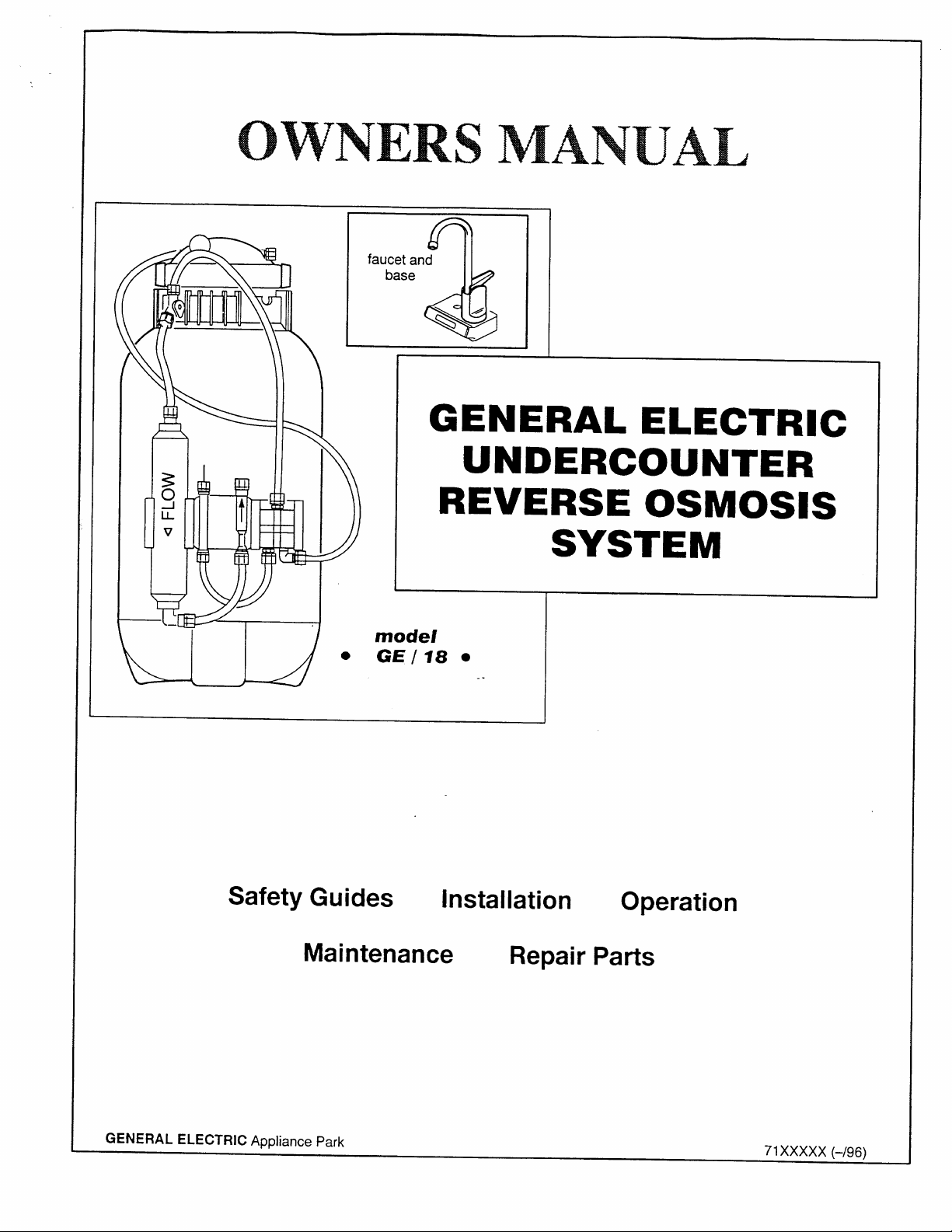
OWNERS MANUAL
faucet and
base
%)”
a
GENERAL ELECTRIC
UNDERCOUNTER
REVERSE OSMOSIS
SYSTEM
I
b---u-d”
Safety Guides
model
GE/18 ●
Maintenance
..
installation
Repair Parts
Operation
GENERAL ELECTRIC Appliance Park
XXXXX (-/96)
71
Page 2
TABLE OF CONTENTS
PAGE NO.
Specifications
What the Drinking Water System will do
Components of the system
Checks to make before installing
Installing
3
3
4 Maintenance
4
5-8
SAFETY GUIDES
Read all steps, guides and rules carefully before
installing and using the Undercounter RO System.
Follow all steps exactly to correctly install.
BE SURE TO FOLLOW APPLICABLE STATE AND LO-
CAL PLUMBING AND SANITATION CODES when
installing the Undercounter RO system. Using a quali-
fied installer is recommended.
The Undercounter RO System works on water pres-
sures of 40 psi minimum, to 125 psi maximum (seethe
table on page 3). If house water pressure is over the
maximum, install a pressure reducing valve in the water suppiy line to the Undercounter RO System.
PAGE NO.
Pressure testing
How the Drinking Water System works
Sanitizing the RO System
Repair parts
DO NOT install the Undercounter RO System outside,
or in extreme hot or cold temperatures. Temperature
of the water supply to the Undercounter RO System
must be between 40”F (minimum) and 80 or 100°F
(maximum) ...see the table on page 3. DO NOT
INSTALL ON HOT WATER.
Read the other limits (pH, water hardness, etc.), page
3, and be sure the water supply conforms.
Do not use the system on microbiologically unsafe
water, or water of unknown quality.
9-10
11–14
15
16-17
9
WARRANTY INFORMATION
2
Page 3
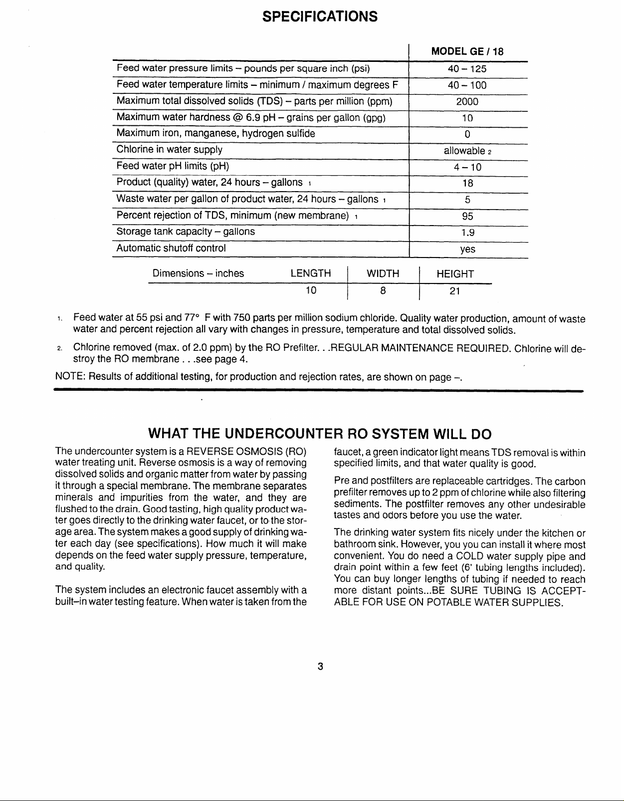
SPECIFICATIONS
[ MODEL GE / 18
Feed water pressure limits - pounds per square inch (psi)
Feed water temperature limits
- minimum / maximum degrees F
I
I
40–125
40–100
Maximum total dissolved solids (TDS) – parts per million (ppm) 2000
Maximum water hardness @ 6.9 pH - grains per gabn (gpg) 10
Maximum iron, manganese, hydrogen sulfide
Chlorine in water supply
Feed water pH limits (pH)
I
I
o
allowable z
4–lo
Product (quality) water, 24 hours - gallons I 18
Waste water per gallon of product water, 24 hours – gallons
I
I
5
Percent rejection of TDS, minimum (new membrane) 1 95
Storage tank capacity - gallons
Automatic shutoff control
Dimensions - inches
LENGTH
10
I
WIDTH
8 21
1.9
yes
HEIGHT
I. Feed water at 55 psi and 77o F with 750 parts per million sodium chloride. Quality water production, amount of waste
water and percent rejection all vary with changes in pressure, temperature and total dissolved solids.
z. Chlorine removed (max. of 2.0 ppm) by the RO Prefilter. .
.REGULAR MAINTENANCE REQUIRED. Chlorine will de-
stroy the RO membrane. . see page 4.
NOTE: Results of additional testing, for production and rejection rates, are shown on page –.
WHAT THE UNDERCOUNTER RO SYSTEM WILL DO
The undercounter system is a REVERSE OSMOSIS (RO)
water treating unit. Reverse osmosis is a way of removing
dissolved solids and organic matter from water by passing
it through a special membrane. The membrane separates
minerals and impurities from the water, and they are
flushed to the drain. Good tasting, high quality productwater goes directly to the drinking water faucet, or tothe storage area. The system makes a good supply of drinking water each day (see specifications). How much it will make
depends on the feed water supply pressure, temperature,
and quality.
The system includes an electronic faucet assembly with a
built–in water testing feature. When water is taken from the
faucet, a green indicator light means TDS removal is within
specified limits, and that water quality is good.
Pre and postfilters are replaceable cartridges. The carbon
prefilter removes up to 2 ppm of chlorine while also filtering
sediments. The postfilter removes any other undesirable
tastes and odors before you use the water.
The drinking water system fits nicely under the kitchen or
bathroom sink. However, you you can install it where most
convenient. You do need a COLD water supply pipe and
drain point within a few feet (6’ tubing lengths included).
You can buy longer lengths of tubing if needed to reach
more distant points...BE SURE TUBING IS ACCEPTABLE FOR USE ON POTABLE WATER SUPPLIES.
Page 4
COMPONENTS OF THE SYSTEM
The factory assembled RO system is shippedinI carton.
A parts bag includes the RO product water faucet and tubing adaptor fittings. All tubing (6 ft lengths), required for
installation, is attached to the RO system. An additional 27
in. length is provided to connect between the faucet and
the drain point. This electronic model also includes a package of special faucet base parts.
THINGS TO CHECK BEFORE YOU START TO INSTALL
●
FEED WATER - The water supply to the undercounter RO system must have the qualities listed in the
specifications. If not, it will not make product water as
it should and life of the RO membrane is shortened.
City water most often will have these qualities. Well
water may need conditioning. Have the water tested
by a water analysis Iabatory, and get their recommendations for treatment. Observe plumbing codes when
providing a water supply to the RO. A self–piercing
saddle valve is included for tapping into a cold water
pipe (check local codes). Refer to pages 5 and 17.
CAUTIONS:
MODEL GE/ 18- Feed water must have all chlorine
removed (prefilter removes up to 2.0 ppm). Chlorine
will destroy the R
to service the prefilter at suggested intervals, page 11.
O membrane cartridge. Be sure
INSTALLER PROVIDES: The water supply valve and
drain fitting (pages 5 and 6) are included for use in areas
where codes permit. Both items nwst comply with
state and/ or /oca/ codes. If not, the installer must provide, (1)fittings to tap the cold water pipe for a feed water
source to the RO...must adapt to 1/4” OD tubing; and (2)
a drain point for RO discharge water...must adapt to 3/8’
OD tubing.
●
DRAIN POINT - A suitable drain point (check your
local codes) is needed for reject water from the RO
membrane cartridge. We suggest using the SINK P–
TRAP drain pipe. A drain clamp (drilling required) is
included to use where codes permit. Refer to pages
6 and 17.
●
RO FAUCET - The RO product water faucet installs
on the sink, or on the countertop next to the sink.
Often, it’s installed in an existing sink spray attachment hole. Space is required underneath for tubing to
and from the faucet, and for securing it in place. All
electronic faucet connections and installation procedures are done on or above the sink or countertop.
Refer to page 7 or 8.
..
4
Page 5
FEED WATER SUPPLY
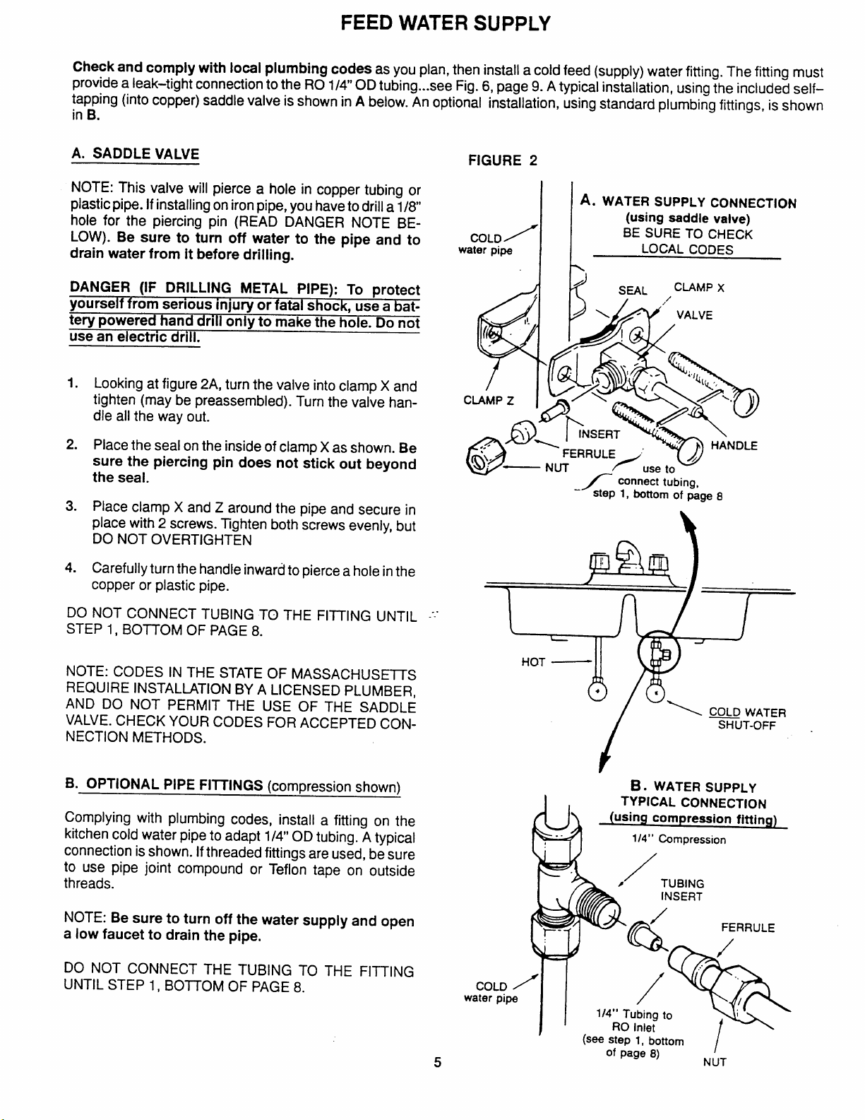
Check and comply with local plumbing codes as you plan, then install a cold feed (supply) water fitting. The fitting must
provide a leak-tight connection to the RO 1/4” OD tubing...see Fig. 6, page 9. A typical installation, using the included self-
tapping (into copper) saddle valve is shown in A below. An optional installation, using standard plumbing fittings, is shown
in B.
A. SADDLE VALVE
NOTE: This valve will pierce a hole in copper tubing or
plastic pipe. If installing on iron pipe, you have to drill a 1/8
hole for the piercing pin (READ DANGER NOTE BELOW). Be sure to turn off water to the pipe and to
drain water from it before drilling.
DANGER (IF DRILLING METAL PIPE): To protect
YOWSe!f from serious iniurv or fatal
~erv Dowered hand
-.
drill &nlj to make the h
..* .—--.7..-
shock, Use a bat-
--—.—---
..._..ole. Do not
use an electric drill.
1.
Looking at figure 2A, turn the valve into clamp X and
tighten (may be preassembled). Turn the valve handle all the way out.
2.
Place the seal on the inside of clamp X as shown. Be
sure the piercing pin does not stick out beyond
the seal.
3.
Place clamp X and Z around the pipe and secure in
place with 2 screws. Tghten both screws evenly, but
DO NOT OVERTIGHTEN
FIGURE 2
A. WATER SUPPLY CONNECTION
H
(using saddle valve)
/’
COLD
water pipe LOCAL CODES
BE SURE TO CHECK
c
~= I INSERT
.. “
‘k
$3
‘NUT _
o
FERRULE :
_/ connect tubing
step 1, bottom of p& 8
m
/
use to
1-
IANDLE
1
/
4.
Carefully turn the handle inward to pierce a hole in the
copper or plastic pipe.
DO NOT CONNECT TUBING TO THE FllTING UNTiL ---”
STEP 1, BOl_JOM OF PAGE 8.
NOTE: CODES IN THE STATE OF MASSACFIUSHTS
REQUIRE INSTALLATION BY A LICENSED PLUMBER,
AND DO NOT PERMIT THE USE OF THE SADDLE
VALVE. CHECK YOUR CODES FOR ACCEPTED CON-
NECTION METHODS.
B. OPTIONAL PIPE FIITINGS (compression shown)
Complying with plumbing codes, install a fitting on the
kitchen cold water pipe to adapt 1/4” OD tubing. A typical
connection is shown. If threaded fittings are used, be sure
to use pipe joint compound or Teflon tape on outside
threads.
NOTE: Be sure to turn off the water supply and open
a low faucet to drain the pipe.
DO NOT CONNECT THE TUBING TO THE FllTING
UNTIL STEP 1, BOJTOM OF PAGE 8.
5
COLD ~
water pipe
HOT —
&(
~-
%
F
I
using compre~ion fitting)
.-
1/4” Tubing to
RO Inlet
(see step 1, bottom
of page 8)
\
SHUT-OFF .
B . WATER SUPPLY
TYPICAL CONNECTION
Compression
1/4”
/
#
TUBING
INSERT
/
Q
/
,..
NUT
FERRULE
/
-.
/
t’
/
Page 6
REJECT WATER DRAIN FITTING
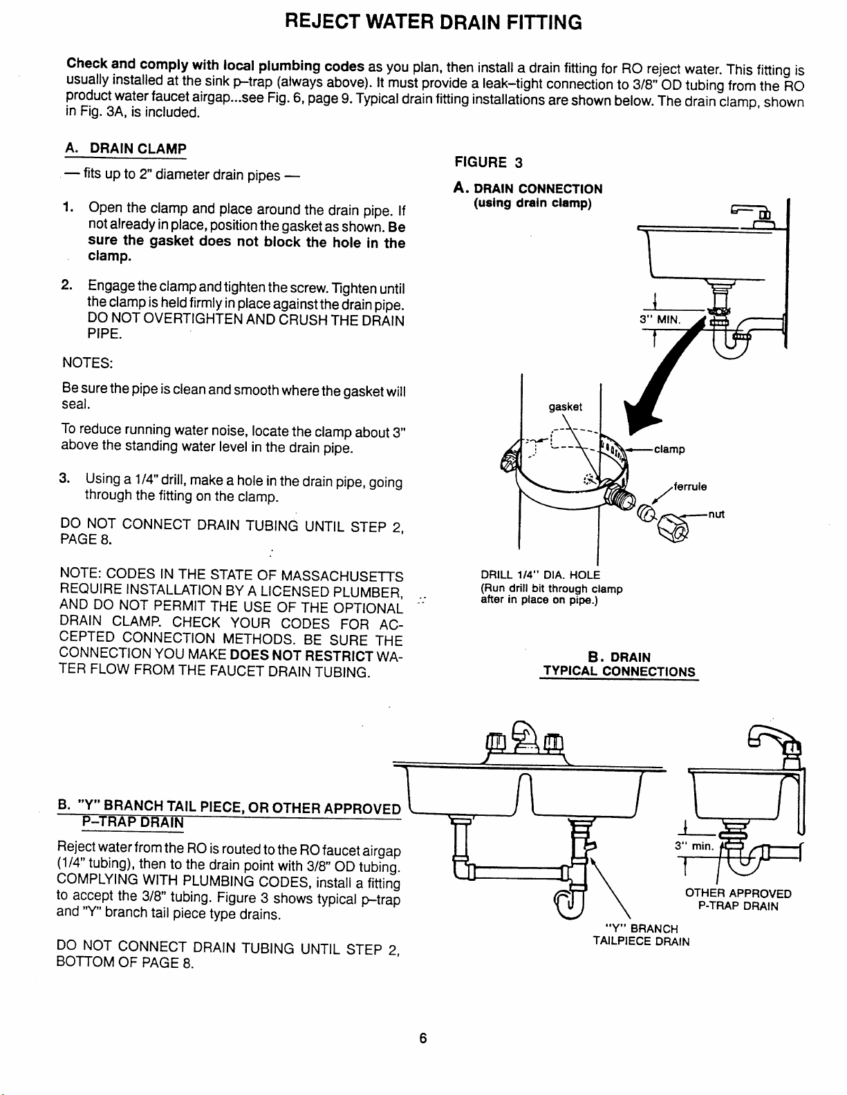
Check and comply with local plumbing codes as you plan, then install a drain fitting for RO reject water. This fitting is
usually installed at the sink p-trap (always above). it must provide a leak-tight connection to 3/8 OD tubing from the RO
product water faucet airgap...see Fig. 6, page 9. Typical drain fitting installations are shown below. The drain clamp, shown
in Fig. 3A, is included.
A. DRAIN CLAMP
— fits up to 2 diameter drain pipes —
1. Open the clamp and place around the drain pipe. If
not already in place, position the gasket as shown. Be
sure the gasket does not block the hole in the
clamp.
2. Engage the clamp and tighten the screw. llghten until
the clamp is held firmly in place against the drainpipe.
DO NOT OVERTIGHTEN AND CRUSH THE DRAIN
PIPE.
NOTES:
Be sure the pipe is clean and smooth where the gasket will
seal.
To reduce running water noise, locate the clamp about 3“
above the standing water level in the drain pipe.
FIGURE 3
DRAIN CONNECTION
A.
(using drain clamp)
gasket
,---- ~.
A
3. Using a 1/4” drill, make a hole in the drain pipe, going
through the fitting on the clamp.
DO NOT CONNECT DRAIN TUBING UNTIL STEP 2,
PAGE 8.
NOTE: CODES IN THE STATE OF MASSACHUSETTS
REQUIRE INSTALLATION BY A LICENSED PLUMBER,
AND DO NOT PERMIT THE USE OF THE OPTIONAL ‘:
DRAIN CLAMP. CHECK YOUR CODES FOR AC-
CEPTED CONNECTION METHODS. BE SURE THE
CONNECTiON YOU MAKE DOES NOT RESTRICT WATER FLOW FROM THE FAUCET DRAIN TUBING.
B. “Y” BRANCH TAIL PIECE, OR OTHER APPROVE
P-TRAP DRAIN
Reject water from the RO is routed to the RO faucet airgap
(1/4” tubing), then to the drain point with 3/8 OD tubing.
COMPLYING WITH PLUMBING CODES, install a fitting
to accept the 3/8” tubing. Figure 3 shows typical ~trap
and “Y” branch tail piece type drains.
DO NOT CONNECT DRAIN TUBING UNTIL STEP 2,
BOITOM OF PAGE 8.
DRILL 1/4” DIA. HOLE
(Run drill bit through clamp
after in place on pipe.)
B. DRAIN
TYPICAL CONNECTIONS
u\
“Y” BRANCH
TAILPIECE DRAIN
OTHER APPROVED
P-TRAP DRAIN
6
Page 7

INSTALL ELECTRONIC FAUCET
li!ii
Select one of the following places to install the faucet. Be
sure there’s room underneath so you can make the needed connections.
NOTE: Looking at Fig. 4D, be sure the faucet base will fit
~lat against the surface, at the selected Iocatlon, so the
gasket will seal.
—
In an existing sink spray attachment hole.
—
Drill a hole in the sink top.
—
Drill a hole in the countertop, next to the sink.
1.
If drilling is needed, make a 1-1/4” dia. hole (mini-
mum). Be sure to use proper procedures for dri/-
iing porcelain or stainless steel.
2.
Place plumbers putty around the drilled hole.
3.
Looking at Fig. 4A, insert a screw into the NON–
SLOITED base mounting hole. Turn a special nut a
few turns onto the screw.
4.
Position the base gasket over the mounting hole. Set
the base on the gasket, routing the leadwire through
the mounting hole. Holding the special nut under the
sink with 1 finger, tighten the screw until just snug.
Turn the remaining special nut a few turns onto the
5.
other screw. Position the screw in the slotted base
mounting hole, and tighten until. snug. Carefully
tighten both screws until the base is held firmly in
place. Do not overtighten and break the base.
NOTE: If the faucet is unassembled, slide the lever over
the small cylindrical nut. Then, push or turn the spout into
the faucet body.
Assemble the top gasket, top faucet base, and hex
6.
nut onto the faucet stud...Fig. 4C. Tighten the nut until
snug. Other included faucet parts are
7.
Using the washer, Fig. 4D, turn the tubing adaptor
onto the faucet stud and tighten securely.
Take the 27” length of 3/8 tubing and push 1 end onto
8.
the 3/8” faucet barb fitting...Fig. 4D.
not used
FIGURE 4
lever ‘
?’il
a
\.=., H base
h
..
-.
x ‘W”l c
faucet
,
top gasket
top faucet
1/4” barb
fitting
318” tubing,
27” {ong
1-1/4” hole
B.
-4iiF
gasket
LOCATE BASE OVER
HOLE AS SHOWN
FAUCET
.
4$
ASSEMBLED
D.
?(J)
.&;
i- *
%
‘3$; - “
r-
I
.—
--
.-
1
Y-l
-.
.
r)
3/8” bacb
fitting
Move the ro system into position, under the sink.
9.
Route the 1/4” tubing (marked “1/4 BARB ON FAUCET’), and the 3/8” tubing (marked “FAUCET”), from
the bottom, up through the mounting hole and faucet
base. Connect to the faucet as follows...see Fig. 4D:
a. Push 1 end of the 1/4” tubing onto the 1/4” barb on
the faucet.
b. Using the tubing adaptor nut, fasten the 3/8” tubing
to the tubing adaptor, and tighten the nut.
10.
Lower the faucet assembly and lock into place on the
faucet base.
1/4” tubing ‘
(1/4” BARB)
NOTE: FOR EASE OF SERVICE AND
MAINTENANCE, KEEP TUBING
LENGTHS LONG ENOUGH SO REMOVAL OF THE RO SYSTEM FROM
UNDER THE SINK IS POSSIBLE.
///’./////7
faucet base
Ieadwire
Page 8

CONNECT WATER SUPPLY AND FAUCET DRAIN TUBING,
ELECTRONIC FAUCET LEADWIRES
1. Run the 1/4” tubing ( marked “WATER SUPPLY”) from
the RO system, to the feed water supply fitting, installed
on page 5. Connect the tubing as applies (Fig. 2A or 2B)
and tighten the nut securely. Also refer to Fig. 6, page 9.
2. Run the 3/8” tubing from the 3/8” faucet barb, to the
drain fitting installed on page 6. Keep this tubing run as
straight as possible, without loops, dips or low-spots.
Cut the tubing as needed and fasten to the drain fitting
TYPICAL FINISHED
FIGURE 6
2
(Fig. 3A or 3B), securing as required,
3. Remove the electronic box back cover and, looking at
Fig. 6, fasten the battery connector to the battery pack (be
sure batteries are installed correctly). Put the battery pack
in the electronic box and replace the back cover.
Fasten the electronic box leadwire to the faucet base leadwire...Fig. 6.
INSTALLATION
I_
Electronic Faucet
RO MODEL
GE/18
..
) //
8
Page 9

PRESSURE TESTING
DO THE SANITIZING PROCEDURES, ON PAGE 15, BEFORE CONTINUING BELOW.
1. Doubl~heck all tubing connections to be sure they
are tightened. system. At that time, carefully check all fittings and
2. Turn on the water supply to the RO system, and open
the tank shutoff valve...Fig. 6.
4. IMPORTANT PURGING INSTRUCTIONS: The RO cartridge contains a food grade presewative that you should
clean from it before using the system. The preservative will give product water an unpleasant taste and odor. After
the bladder has filled (takes about 4 hours), open the system faucet until the bladder is empty. Allow the bladder to
fill again for 4 hours, then open the faucet and empty. After 4 purgings, the system is ready to make product water
.for your use.
3. In about 4 hours, pressure will start to build in the RO
tubing connections for any water leaks. Correct leaks
if any are found.
HOW THE UNDEI?COUNTER RO SYSTEM WORKS (FIG. 7)
PREFILTER
Water from the cold supply pipe enters the RO assembly
and is directed to the prefilter cartridge.
NOTE: Before going to the prefilter, supply water first
passes through the electronic box to measure total dissolved solids (TDS).
The prefilter is a replaceable sediment cartridge with acti-
vated carbon in its composition. The cartridge (5 micron)
removes sand, silt, dirt, other sediments, and up to 2.0
ppm of chlorine from the feed water., CHLORINE DESTROYS THE ERO 392 MEMBRANE. Filtered, clean,
chlorim+free water flows from the prefilter, to the RO
membrane cartridge. IMPORTANR See prefilter main-
tenance, page 11.
REVERSE OSMOSIS (RO} CARTRIDGE
The cartridge, inside the RO housing, includes a tightly
wound, special membrane. Water is forced through the
cartridge where the membrane removes the dissolved
solids and organic matter. High quality product water exits
the RO housing and goes to the storage area. Reject water, with the dissolved solids and organic matter, leaves
the housing and is discharged to the drain through 1/4”
tubing.
NOTE: On electronic models, product water passes
through the electronic box before going to the faucet, to
measure total dissolved solids (TDS).
continued
FIGURE 7
~ shutoff
4*
G
supply water
—
iJ-J
● “
tank
..
shutoff -—.
..
product water”:
to postfilter
and faucet
H
,
)
automatic
assembly
4
to drain
PRODUCT WATER STORAGE
The storage area holds up to 1.7 gallons of product water.
The flexible bladder keeps water pressurized for fast flow
to the faucet when drinking water is needed.
POSTFILTER
After leaving the storage area, but before going to the faucet, product water goes to the postillter. The postfilter is
also the activated carbon type sediment filter. Any remain-
ing tastes, odors, or sediments are removed from product
water. Tast&free, odor–free, clean, high quality drinking
water flows through the tubing and to the faucet.
check
valve
product
water
RO housing
.
- bladder
Page 10

HOW THE UNDERCOUNTER RO SYSTEM WORKS (FIG. 7)
FAUCET AND ELECTRONICS
The sink or countertop faucet vends the drinking water
when opened. it has a hand operated, spring loaded
closed lever to prevent waste. You can also keep the faucet open by pushing upward on the lever and locking it
against the faucet spout.
To comply with plumbing codes, an air-gap is built into the
faucet drain water connection.
The electronic faucet provides a built–in water quality tester. As water is taken from the faucet, the indicator lights
show how the RO system is operating to provide high
quality drinking water.
● FLASHING GREEN LIGHT - The RO system is giv-
ing you high quality drinking water.
NOTE: The green light may stop flashing when the supply
of RO water is nearly gone, and flow from the RO faucet
decreases. This is a normal condition.
● FLASHING RED “FILT” LIGHT - The prefilter car-
tridge and postfilter need replacing. This occurs after
6 months, or 900 gallons of product water use. Also
replace the control box batteries... see page 12.
● FLASHING AMBER “RO” LIGHT - The RO car-
tridge no longer removes at least 75% of the TDS from
supply water and needs replacement.
NOTE: Disregard initial or short periods of the flashing
“ROY’ light.
SHUTOFF ASSEMBLY
To conserve water, the drinking water system has an automatic shutoff assembly. When the storage tank has filled
to capacity, and the drinking water faucet is closed, pres-
sure closes the shutoff. Water flow to the RO housing is
shut off until drinking water is used again, and pressure
drops in the RO system.
CHECK VALVE
A check valve (Fig. 7) is buiit into the bottom end of the RO
housing. The check valve prevents a backward flow of
product water from the storage area. A backward flow
could cause TDS to bleed into the product water, and
could rupture the RO membrane.
FLOW CONTROL
The flow control (see Fig. 8) regulates flow, through the
RO cartridge, to the required rate to get the desired quality
of product water. The control is located in the drain tubing,
at the RO cap fitting. A small, corwshaped screen fits
over the front end of the flow control to help prevent plugging with drain water sediments.
10
Page 11

MAINTENANCE
(
AlSO see Filter-cartridge Replacement Guide, page 14 )
To keep the undercounter RO system operating and mak-
ing high quality drinking water, the prefilter cartridge, RO
cartridge, and postillter need replacement at certain intervals. Use the following information to keep the RO system
properly sewiced and maintained.
——— —6——— ——— —,
r
I
BEFORE SERVICING THE RO SYSTEM, DO THE FOL-
LOWING TO RELIEVE PRESSURE AND ALLOW AIR
I
TO ENTER THE RO TANK.
ID
1‘Tu~off~e ~e~p~to~e ~.
2. Open the product water faucet and allow water to run
until it stops.
3. Using a 2 gal (minimum) container to catch the water,
disconnect the postfilter. Allow the storage bladder to
empty.
4. Looking at Fig. 8, remove the protective cap and depress the vacuum relief valve stem, allowing air to en-
ter the tank. Release the valve stem after flow from
the tank shutoff slows to a slight drip. Replace the protective cap.
CAUTION: This valve is for vacuum relief only. DO NOT
attempt to pressurize the tank.
CAUTION:
———
FIGURE 8
cone screen
..
1
1
I
J
R~ Cap /“~ ‘ ‘
91
o-ring
UP
4
arrow
protective
cap
M“ Kg:’s
vacuum
‘.
.
i
UP
K
@
i
.
RO
flow control
“=
membrane
cartridge
1/11—
‘h ~
-= retainer (2)
5. Reconnect the postfilter.
PREFILTER CARTRIDGE AND POSTFILTER RE-
PLACEMENT
You must replace the prefilter cartridge often to protect the RO membrane from being destroyed by chlorine, and/or from plugging with sediments in the water
supply. Ifthe water suppl y contains both chlorine and sediments, replace the prefilter cartridge at least every-6
months, or more often if it begins to plug with sediments.
If the water has sedhnents on/~ with no chlorine, you may
begin to notice a slower making of product water. When
this happens, a new sediment cartridge is needed. Also
replace the postfilter.
To signal correct replacement interval, the red “FllT” indicator light, on the electronic faucet base, will beginto flash
after6 months, or 900 gallons of product water use, which-
occurs first.
ever
At the same time, replace the batteries in the control box.
Replacing the batteries resets the 6 month or 900 gallon
period, and assures proper operation of the RO indicator
Iight...see page 12.
postfi!ter
-
-.
.—,
\
\
Shutoff assembly
not shown. See
Pages 9,13 and 16.
%-H
Maintenance continued, page 12
11
Page 12

MAINTENANCE
● sT~ps To REpLAcE T~EposTF\LTERo
IMPORTANT Read the caution on page 11 and do
steps 1-4, to relieve pressure in the RO, before continu-
ing below.
1. Disconnect tubing at both ends... see Fig. 8.
2. Pull the filter from the holder and remove fittings from
both ends
NOTE: Both ends of the postfilter may be externally
threaded to accept the tubing nuts directly without the t7t-
Just be sure the flow arrow points downward.
tings.
If needed, turn the fittings (use Teflon tape) into both
3.
ends of the postfilter, observing the flow arrow.
4. Replace filter into the holder and reconnect the tubing
at both ends.
● STEPS TO REPLACE THE PREFILTER CARTRIDGE ●
IMPORTANT Read the caution on page 11 and do
steps 1-4, to relieve pressure in the RO before continu-
ing below.
1.
Referring to Fig. 8, remove the clamp retainers and
clamp sections.
2. Separate the cap from the RO housing (no need to
disconnect tubing) and set aside.
NOTE: If the cap o+ing seal remained in the RO housing, replace it on the cap.
It’stime to replace the RO cartridge when product water
quality and/or rate of production drop (first replace the prefilter cartridge and postfilter). Product water may begin to
taste different or even bad, indicating solids and organics
getting through the cartridge.
are
NOTE: When replacing the RO cartridge, also install a
new flow control and screen. The prefilter cartridge and
postfilter should also be replaced.
ELECTRONIC MODELS — it’s time to replace the RO
cartridge when the amber “RO” light, on the faucet base,
flashes continually while RO water is taken from the fau-
cet...see page 10.
c STEPS TO REPLACE THE RO CARTRIDGE ●
1. Do all steps under “To Replace The Prefilter Car-
tridge”, also on this page.
2. Remove and replace the flow control and
screen... see below.
3. Turn on the water supply and PURGE THE RO CAR-
TRIDGE...SEE PAGE 9.
BAITERIES IN ELECTRONIC CONTROL BOX
Always replace the 4, “AA” alkaline batteries in the control
box when changing the prefilter cartridge and postfilter.
Good batteries are needed to assure proper indicator light
operation. Weak batteries may give a false indication.
Changing the batteries also resets the 6 month or 900 gallon period.
3. Lift the RO cartridge and prefilter cartridge from the ‘housing. Separate and dispose of the prefilter car-
tridge.
4. Dump water from the RO housing.
5. Slide the RO cartridge INTO THE TOP END of the
new prefilter cartridge, as shown in Fig. 8. Then,
place into the RO housing.
NOTE: Be sure the bottom end of the prefilter is at the
bottom, and the UP arrow on the RO cartridge points
upward.
6. Lubricate the cap o-ring seal (silicone grease). Then,
push the cap into position and install the clamp sections and retainers.
RO CARTRIDGE
The life of the RO cartridge depends mostly on the pH of
properly treated feed water... see pages 3 and 4. The higher the pH, the shorter cartridge life is. For example, if feed
water pH is from 6.8 to 7.7, the cartridge may last for well
over 1 year. However, cartridge life may be as short as 6
months if the pH is as high as 8.0 or 10 (see specifica-
tions). The higher pH weakens the cartridge membrane
and makes pin–hole leaks.
FLOW CONTROL AND SCREEN
The flow control is vital for proper operation of the RO cartridge. The control must keep water flow through the cartridge at the proper rate to obtain the best quality product
water.
When servicing the RO, it’s good practice to check the
flow control (and tubing to it) to make sure the small tube
and surrounding surfaces are clean and unrestricted. A
small, cone-shaped screen (Fig. 8) is located in front of
the flow control to help keep it clean. If the flow control
should plug with foreign particles, the RO cartridge cannot
discharge minerals and impurities to the drain. If this
should happen, it will only take a short time for the cartridge to plug, making it useless.
CAUTIONS:
To install the screen, place the cone end into the RO cap.
Then, carefully push it in using l/4’’ tubing as a tool. Do not
force in farther after you feel resistance. Visually check to
be sure it is properly positioned.
When installing the flow control, tighten the tubing nut by
hand, then another 1/4 to 1/2 turn with a pliers. DO NOT
OVERTIGHTEN AND DISTORT OR CRUSH THE TUB-
ING AND FLOW CONTROL.
12
Page 13

MAINTENANCE
SERVICING THE BLADDER
If the bladder should require inspection and replacement,
use the following guides. Refer to the parts illustration on
page 16.
NOTE: READ THE CAUTION ON PAGE 11 AND DO
STEPS 1-4, TO RELIEVE PRESSURE IN THE RO BE-
FORE CONTINUING BELOW.
1. Remove the vacuum relief valve using a 7/1 6“ socket.
2. Rotate the tank shutoff valve 90° and pull from the RO
housing.
—.-—— ——-—- ———-— ———. — .—
r
1“
I DO NOT USE VINEGAR, OR OTHER ACID I
I BASED CLEANERS ON THIS RO SYSTEM. 1
I THEY WILL DEGRADE SOME RO SYSTEM I
I PARTS. ALWAYS USE SOAP AND WATER. j
L —--— ———— ——-— ——. — ———— —.
-———— —--—— ————— ————— ——
r
I This reverse osmosis system contains a replace- ~
I able treatment component critical for effective re- ,
I
moval of total dissolved solids. The water should be
I tested periodically to verify the system is performing ~
I satisfactorily.
I I
i ———— ———— ———— ———— ———— ——
CAUTION
7
1
J
3. Apply downward pressure on the RO cap while rotating it counterclockwise 90”.
NOTE: If the cap turns in the RO housing, first do steps
1 and 2 under “To Replace The Prefilter Cartridge”, page
12.
4.5.Lift the RO housing out of the liner assembly and
PLACE WHERE CLEAN AND SANITARY.
Remove the bladder.
NOTE: BE SURE THE INNER SURFACE OF THE RE-
PLACEMENT BLADDER, ANI) THE OUTER SURFACE
OF THE RO HOUSING ARE CLEAN. USE DISH SOAP
AND HOT WATER TO CLEAN AND RINSE.
6.
Install the bladder into the liner assembly. Wet the top .
bead of the bladder with water, or apply a light coatirlg
of silicone grease.
Install the RO housing, push downward and rotate
7.
clockwise 90° to lock in place.
Replace the tank shutoff valve and rotate 90° to Io-ck.
8.
FIGURE 9
SHUTOFF
ASSEMBLY
(4)
\
diaphragm
e
Using pipe joint compound, replace the vacuum relief
9.
valve.
10.
DO THE SANITIZING AND PURGING PROCE-
AUTOMATIC SHUTOFF SERVICE
If the shutoff assembly requires service, be sure to reassemble parts exactly as shown in Fig. 9, and to reconnect
tubing as shown on pages 9 and 16.
diaphragm
e
Elbow fitting turns
into OUT port and
connects to RO
13
Page 14

FILTER - CARTRIDGE REPLACEMENT GUIDE
IMPORTANT Before doing maintenance on the ro system, relieve pressure and allow air
to enter the tank, steps 1 – 5, page 11.
MODEL GE/ 18
AT LEAST EVERY 6 MONTHS
– Replace sediment-carbon prefilter cartridge and postfilter...see
important note above. Also see Electronic Indicator, below.
- Make replacements indicated if any of the following occur
before the 6 months, -
CHLORINE TASTE AND/OR ODOR
– Replace prefilter cartridge, postfilter, RO cartridge, flow control
and screen... see important note above.
OTHER TASTE ANDIOR ODOR
- Replace the postfilter...see important note above.
– If taste and odor persists, replace prefilter cartridge, RO cartridge, flow control and screen.
SLOW PRODUCTION RATE
– Replace prefilter cartridge... see important note above.
– If rate does not increase, replace postfilter, RO cartridge, flow
control and screen.
HIGH TDS
– Replace prefilter cartridge, postfilter, RO cartridge, flow control
and screen... see important note above.
SLOW FLOW FROM RO FAUCET
– Relieve pressure and allow-air to enter the tank, steps
page 11.
1-5,
ELECTRONIC INDICATOR
BE SURE TO COMPLY WITH THE IMPORTANT NOTE ABOVE.
AT LEAST EVERY 6 MONTHS OR 900 GALLONS OF RO PRODUCT WA-
USE
ER
postfilter, and batteries in the electronic control box.
WHEN THE AMBER “ROS’ LIGHT FLASHES ...
– Replace the RO
Rt D “FILT” LIGHT FLASHES – Replace the prefilter cartridge,
...
cartridge, flow control and screen.
14
Page 15

SANITIZING THE RO SYSTEM
Sanitizing is recommended upon installation of the RO
system, and after servicing inner par&s of the RO housing
and cap. It is
important for the service person to have
clean hands while handling inner parts of the system.
1. Be sure the water supply to the RO is turned off, and
the RO faucet is open.
2. Remove the clamp retainers and clamp sections, Fig.
8, page 11.
3. Lift the cap from the RO housing (no need to disconnect tubing) and move aside.
NOTE: If the cap o+ing seal remained in the ro hous-
ing, replace it on the cap.
4. Remove the RO cartridge and prefilter cartridge
from the RO housing. If needed, flush housing with
fresh, clean water.
5. Fill the RO housing, with fresh water, to about 1“ from
the top. Add 1.0 oz of chlorine (ordinary 5.25% house-
hold bleach... Hilex, Clorox, etc.) and mix in the water.
DO NOT ADD CHLORINE FIRST. Concentrated, it
WIIIattack plastlcs.
6.
Replace the cap, with o-ring, and install the retaining
clamps.
7.
Connect the RO faucet product water tubing directly
to the tank shutoff valve, isolating the carbon postfilter.
8.
Open the tank shutoff valve, and the water supply to
the RO. Open the RO faucet, locking the lever upward against the spout.
9.
Allow water to circulate through the system until all
bleach odor is gone.
10.
Turn off the water supply to the RO. Close the RO faucet after water flow stops.
11.
Reconnect the postfilter (replace a used filter) to the
RO system, Fig. 6, page 9, and page 12.
12.
a
Do steps 2 and 3.
b
Replace the RO cartridge and prefilter cartridge
(BE SURE YOUR HANDS ARE CLEAN).
Do step 6.
Turn to page 9 and do the pressure testing and
purging steps 1 through 4.
PRETREATMENT OF THE WATER SUPPLY
NEEDED TO PREVENT SCALING
TO USE THE CHART...
...Locate the intersecting point of feed water hardness
and pH.
If this point falls within the shaded area, pretreatment* is
needed.
●Softening of the water is the suggested pretreatment.
..
1=
I
RECNJIREn =
,
1
I
10
FEED WATER HARDNESS (GPG)
20
I
I
30 40
I
I
50 60
15
Page 16

RO REPAIR PARTS ILLUSTRATION
\
/
6’
o
(
‘1..,
@
SADDLE VALVE
41
1
OPTIONAL
\
\
\
I +1 *
I
I
LJ
x TO
FAUCET
AIR GAP
,.
I
I
(ial
a
1
.“
—
?
i
~-
9--
..
46
Page 17

RO REPAIR PARTS LIST
Key
No. No.
1
2
3 7051206
4 71
5 0900713
6 71
7 7114614
8 7115725
9 9003204
10
11 7114509
12 7131349
13 9003203
14 71
15
16 71
17
18 7087477
19
20 7115822
21
22
23 7014979 Plunger
24 9004504 Elbow, 1/8” NPT x 1/4” Tube
Part
Description
7095925
7064144
1260600
9043201 Nut, 3/8 Tubing
7131331
7116763 O–ring, 7/16’ x 5/8” – for shutoff
7128524
7127756
1269800
7126506
7112426
7099296
Faucet
Tubing Adaptor–includes washer &
nut
Washer, Compression
Top Gasket
Top, Faucet Base
Screw, #6- 32x 1-3/8’ (2)
Base, Faucet @
Gasket
Nut (2)
Nut, 1/4” Tube (8)
Insert, 1/4” Tube (7)
Tank Shutoff Valve
valve
Insert, 3/8 Tube (5)
Nut, 3/8” Tube (3) @
Post Carbon Filter
Filter Holder
Electronic Box @
Flow Washer “
Magnet
Spring
Battery Holder Q
Cable Extender, 15 ft. (optional)
Valve Bottom
Diaphragm (2)
Key
No.
25 7167683
26
27 7112434 Valve Center
28 7030721
29 7078127
30 7138676
31 0900044
32 7140869
33 7109910
34 7121954
35 7155018
36 7088033
37 7088041 Clamp Section (2)
38 7115610 O-ring, RO Cap
39 7167706
40 7124986
41 7011272
42
43 7095030
44 7167764 Flow Control
45
46
47 7147748
Part
No.
Connector, 1/8” NPT x114° Tube
7112442
7133838
71227’98
71
71
7063889 Tubing, 1/4” – order length needed
0010251 Tubing, 3/8” - order length needed
Valve Top
Screw, #10- 14x 1-3/4” (4)
Shutoff Assem., Incls.
Connector, 1/4” NPT x 1/4” Tube
Liner Assembly
O-ring, 5/16” x 7/16
Vacuum Relief Valve
Bladder
Ball-Check Kit
RO Housing, incls. key no. 34
Clamp Retainer
RO Cap
Elbow, 1/4” NPT x 1/4” Tube
Supply Saddle Valve @
Drain Clamp @
Cone Screen
Repl. RO Cartridge
Pre (Carbon) Filter
Cover Assembly
Description
(2)
21–23, 26-28
@ Includes key nos. 3,4, 5,7 and 8
@includes key nos. 17,18 and 19-orderbattery holder
if needed
@does not include batteries
@ Not included with RO. Not allowed in all localities.
Check your local codes.
 Loading...