

GE GDT530P DO, GDT550H DO, WD35X10396, GDT530P*D0, GDT550H*D0 Installation Instructions Manual
Page 1
GE Appliances
Installation Instructions
Dry Enhancement Kit
WD35X10396
February 2013
Dishwasher Dry Performance
Verify proper heater operation, check for error
codes in diagnostic error mode, including
thermistor and/or wash temperature error codes.
Enter service mode to test heater operation. Full
directions to enter diagnostic and service mode
can be found in service guide 31-9226 or the
dishwasher's mini-manual.
If none of the above issues apply, follow all steps
in these instructions.
Models:
GDT530P DO
GDT550H DO
Parts Included:
This kit includes all parts needed for the above
models.
• UI (User Interface) Board WD21X10535
° 2 Vent Covers
° Foam Strip (black in color)
° Door harness wire tie (may not be needed)
° Installation instructionsWD00X1023
Step I - Remove Power from the
Dishwasher
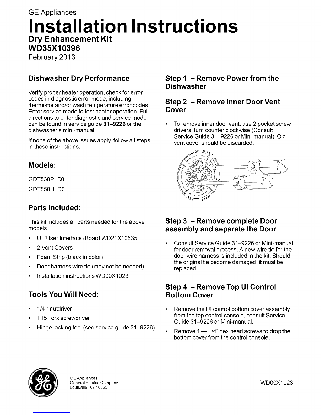
Step 2 - Remove Inner Door Vent
Cover
To remove inner door vent, use 2 pocket screw
drivers, turn counter clockwise (Consult
Service Guide 31-9226 or Mini-manual). Old
vent cover should be discarded.
Step 3 - Remove complete Door
assembly and separate the Door
Consult Service Guide 31-9226 or Mini-manual
for door removal process. A new wire tie for the
door wire harness is included in the kit. Should
the original tie become damaged, it must be
replaced.
Tools You Will Need:
• 1/4" nutdriver
• T15Torx screwdriver
• Hinge locking tool (see service guide 31-9226)
GE Appliances
General Electric Company
Louisville, KY 40225
Step 4 - Remove Top Ul Control
Bottom Cover
Remove the UI control bottom cover assembly
from the top control console, consult Service
Guide 31-9226 or Mini-manual.
Remove 4 -- 1/4" hex head screws to drop the
bottom cover from the control console.
WD00X1023
Page 2
Step 5 - Install new UI Control Board
Control
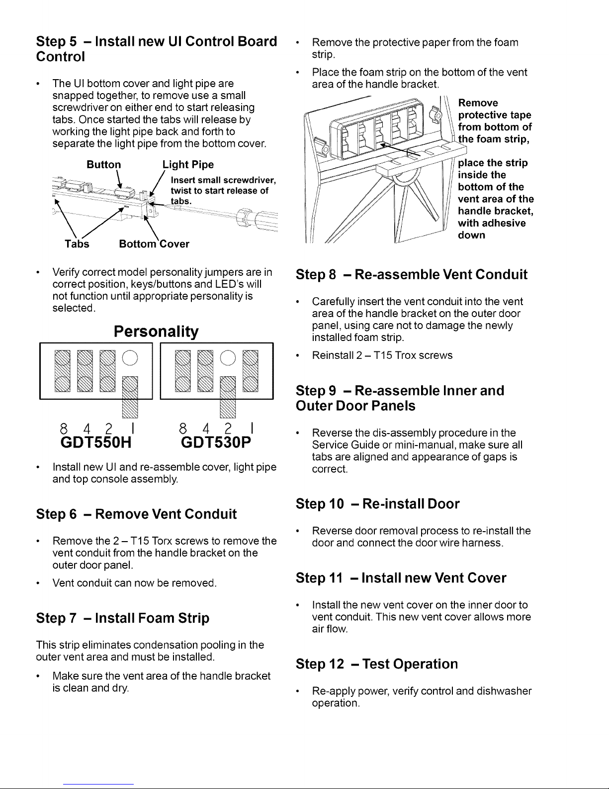
The UI bottom cover and light pipe are
snapped together, to remove use a small
screwdriver on either end to start releasing
tabs. Once started the tabs will release by
working the light pipe back and forth to
separate the light pipe from the bottom cover.
Remove the protective paper from the foam
strip.
Place the foam strip on the bottom of the vent
area of the handle bracket.
Remove
protective tape
from bottom of
foam strip,
Button Light Pipe
Verify correct model personality jumpers are in
correct position, keys/buttons and LED's will
not function until appropriate personality is
selected.
©
8 4 I
GDT550H
Install new UI and re-assemble cover, light pipe
and top console assembly.
8 4 I
GDT530P
©
place the strip
inside the
bottom of the
vent area of the
handle bracket,
with adhesive
down
Step 8 - Re-assemble Vent Conduit
Carefully insert the vent conduit into the vent
area of the handle bracket on the outer door
panel, using care not to damage the newly
installed foam strip.
Reinstall 2 - T15 Trox screws
Step 9 - Re-assemble Inner and
Outer Door Panels
Reverse the dis-assembly procedure in the
Service Guide or mini-manual, make sure all
tabs are aligned and appearance of gaps is
correct.
Step 6 - Remove Vent Conduit
, Remove the 2 - T15 Torx screws to remove the
vent conduit from the handle bracket on the
outer door panel.
, Vent conduit can now be removed.
Step 7 -Install Foam Strip
This strip eliminates condensation pooling in the
outer vent area and must be installed.
° Make sure the vent area of the handle bracket
is clean and dry.
Step 10 - Re-install Door
° Reverse door removal process to re-install the
door and connect the door wire harness.
Step 11 -Install new Vent Cover
• Install the new vent cover on the inner door to
vent conduit. This new vent cover allows more
air flow.
Step 12 - Test Operation
• Re-apply power, verify control and dishwasher
operation.
 Loading...