

Page 1
www.GEAppliances.com
IMPORTANT"These
instructions are needed to
install an icemaker in your
refrigerator. To be used
with an IM4, IM4A or IM6
Icemaker Kit. Keep this
addendum with your
Owner's Manual and
Installation Instructions.
These instructions
are to be used to
install an Icemaker
Kit in the models
listed below.
GBS2OKB
GBS22HB
GBS22KB
PDS2OMB
PDS2OSB
PDS22MB
PDS22SB
197D5736PO02 49-60319 12-03JR
Page 2
Installation Instructions
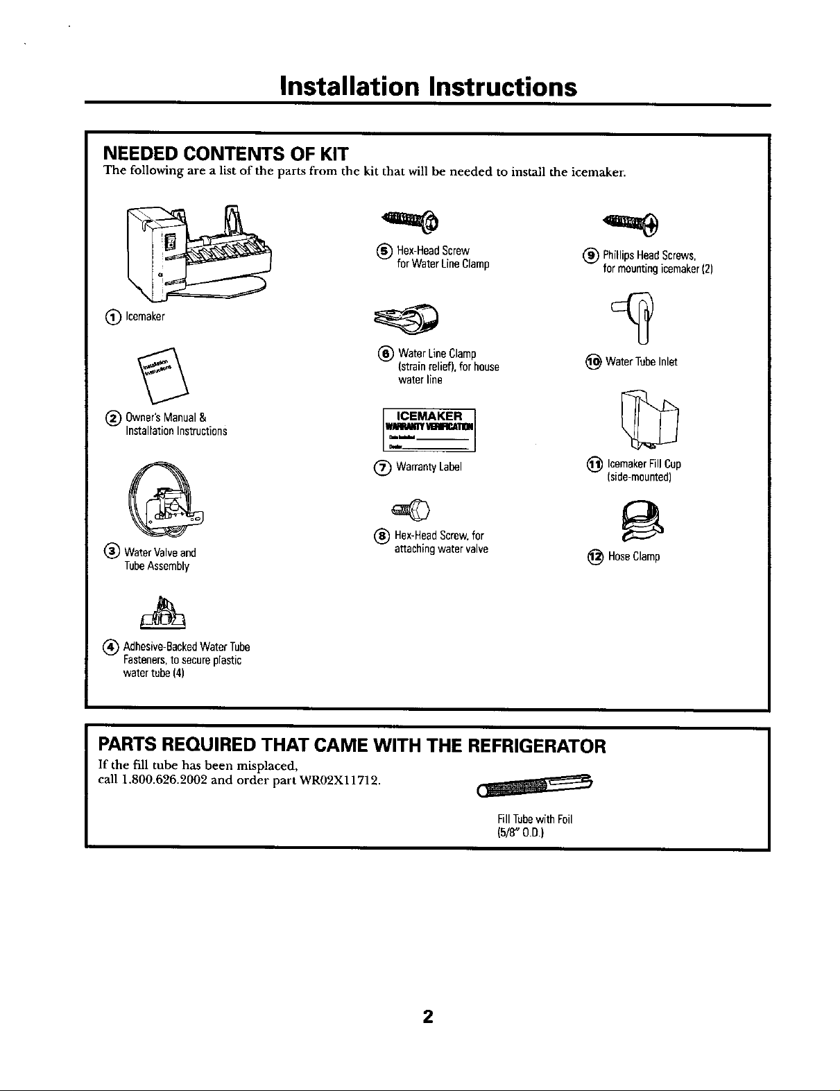
NEEDED CONTENTS OF KIT
The following are a list of the parts from the kit that will be needed to install the icemaker.
(_) Hex-HeadScrew
forWaterLineClamp
(_) Icemaker
(_ WaterLine
(strainrelief),forhouse
waterline
(_ Owner'sManual& ICEMAKER
InstallationInstructions _!ll_
G (_ Warran_Label
WaterValveand -- attachingwatervalve
TubeAssembly
1_ Adhesive-BackedWaterTube
Fasteners.to secureplastic
watertube(4)
_blhl
(_) Hex-HeadScrew.for
Clamp
(_) PhillipsHeadScrews,
formountingicemaker(2)
(_ WaterTubeInlet
(_) IcemakerFillCup
(side-mounted)
_) HoseClamp
PARTS REQUIRED THAT CAME WITH THE REFRIGERATOR
If the fill tube has been misplaced,
call 1.800.626.2002 and order part WR02X11712.
FillTubewithFoil
(518"O.D.)
2
Page 3
Installation Instructions
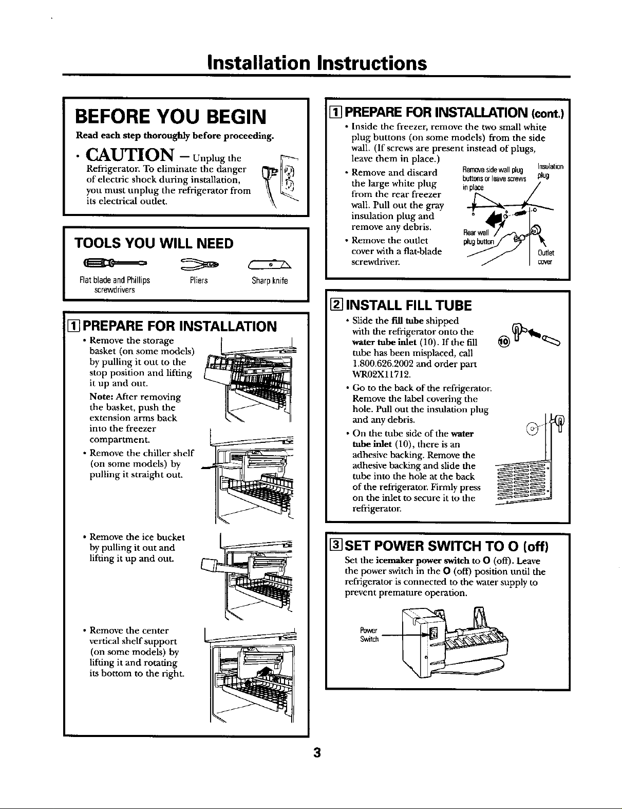
BEFORE YOU BEGIN
Read each step thoroughly before proceeding.
• CAUTION - Unplug the _--
Refrigerator. To eliminate the danger _)_
of electric shock during installafion, _ [.._j
you must unplug the refrigerator from \\its electrical oudet.
TOOLS YOU WILL NEED
FlatbladeandPhillips Pliers
screwdrivers
[] PREPARE FOR INSTALLATION
• Remove the storage
basket (on some models)
by pulling it out to the
stop position and lifting
it up and out.
Note: After removing
the basket, push the
extension arms back
into the freezer
compartment.
• Remove the chiller shelf
(on some models) by
pulling it straight out.
Sharpknife
[] PREPARE FORINSTALLATION (cont.)
• Inside the freezer, remove the two small white
plug buttons (on some models) from the side
wall. (If screws are present instead of plugs,
leave them in place.)
• Remove and discard
the large white plug
from the rear freezer
wall. Pull out the gray
insulation plug and
remove any debris.
• Remove the outlet plugbutton
cover with a flat-blade
screwdriver.
[] INSTALL FILL TUBE
• Slide the fill tube shipped
with the refrigerator onto the
water tube inlet (10). If the fill
tube has been misplaced, call
1.800.626.2002 and order part
WR02X11712.
• Go to the back of the refrigerator.
Remove the label covering the
hole. Pull out the insulation plug
and any debris.
• On the tube side of the water
tube inlet (10), there is an
adhesive backing. Remove the
adhesive backing and slide the
tube into the hole at the back
of the refrigerator. Firmly press
on the inlet to secure it to the
refrigerator.
Removesidewallplug Insulation
I_t_s orleavescrews plug
inplace
• Remove the ice bucket
by pulling it out and
lifdng it up and out.
• Remove the center
vertical shelf support
(on some models) by
lifting it and rotating
its bottom to the right.
[]SET POWER SWITCH TO O (off)
Set the icemaker power switch to O (off). Leave
the power switch in the O (off) position until the
refrigerator is connected to the water supply to
prevent premature operation.
3
Page 4
Installation Instructions
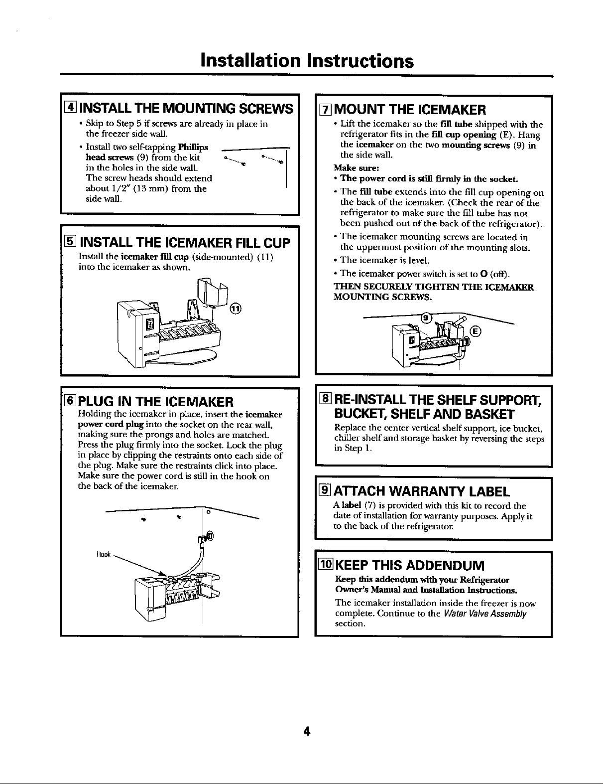
[] INSTALL THE MOUNTING SCREWS
• Skip to Step 5 if screws are already in place in
the freezer side wall.
• Install two self-tapping Phillips
head screws (9) from the kit
in the holes in the side wall.
The screw heads should extend
about 1/2" (13 ram) from the
side wall.
[] INSTALL THE ICEMAKER FILL CUP
Install the icemaker f'dl cup (side-mounted) (11)
into the icemaker as shown.
[] MOUNT THE ICEMAKER
• Lift the icemaker so the t'fll tube shipped with the
refrigerator fits in the fill cup opening (E). Hang
the ieemaker on the two mounting screws (9) in
the side wall.
Make sure:
• The power cord is still firmly in the socket.
• The f'dl tube extends into the fill cup opening on
the back of the icemaker. (Check the rear of the
refrigerator to make sure the fill tube has not
been pushed out of the back of the refrigerator),
• The icemaker mounting screws are located in
the uppermost position of the mounting slots.
• The icemaker is level.
• The icemaker power switch is set to O (off).
THEN SECURELY TIGHTEN THE ICEMAKER
MOUNTING SCREWS.
[]PLUG IN THE ICEMAKER
Holding the icemaker in place, insert the ieemaker
power cord plug into the socket on the rear wall,
making sure the prongs and holes are matched.
Press the plug firmly into the socket. Lock the plug
in place by clipping the restraints onto each side of
the plug. Make sure the restraints click into place.
Make sure the power cord is still in the hook on
the back of the icemaker.
Hook_
[] RE-INSTALL THE SHELF SUPPORT,
BUCKET, SHELF AND BASKET
Replace the center vertical shelf support, ice bucket,
chiller shelf and storage basket by reversing the steps
in Step 1.
[] ATTACH WARRANTY LABEL
A label (7) is provided with this kit to record the
date of installation for warranty purposes. Apply it
to the hack of the refrigerator.
1-_KEEP THIS ADDENDUM
Keep this addendum with your Refrigerator
Owner's Manual and Installation Instructions.
The icemaker installation inside the freezer is now
complete. Continue to the Water Valve Assembly
section.
4
Page 5
Installation Instructions
WATER VALVE ASSEMBLY INSTALLATION INSTRUCTIONS
BEFORE YOU BEGIN
Read each step thoroughly before proceeding.
Refrigerator. To eliminate the danger in
of electric shock during installation,
" CAUTION- Unplug the _
you must unplug the refrigerator
from its electrical outlet.
TOOLS YOU WILL NEED
FlatbladeandPhillips Pliers Sharpknife
screwdrivers
1/4" and5/16"Nutdrivers Tapemeasure
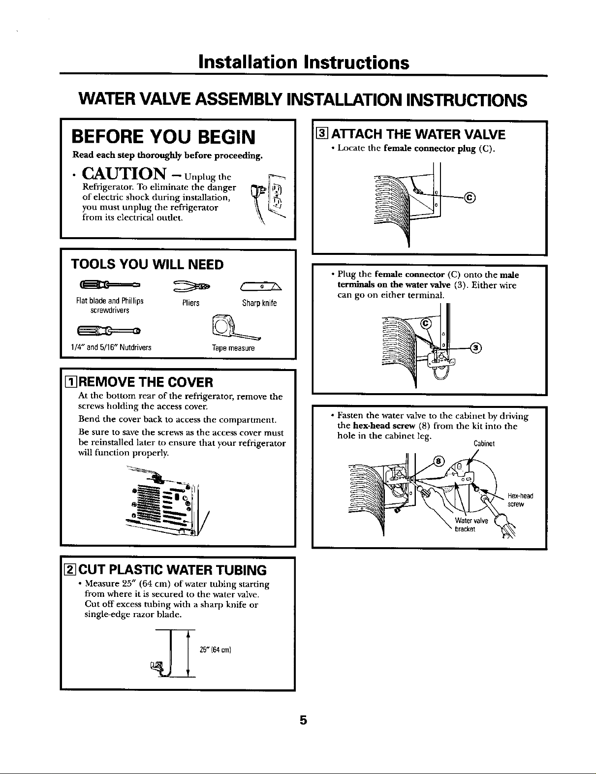
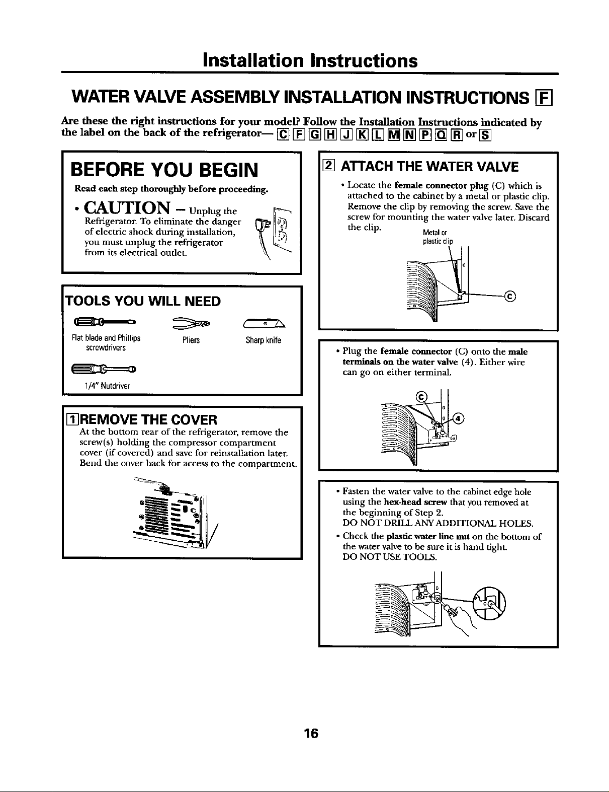
I_REMOVE THE COVER
At the bottom rear of the refrigerator, remove the
screws holding the access cover.
Bend the cover back to access the compartment.
Be sure to save the screws as the access cover must
be reinstalled later to ensure that )'our refrigerator
will function properly.
[] A1-FACH THE WATER VALVE
• Locate the female connector plug (C).
• Plug the female connector (C) onto the male
terminals on the water valve (3). Either wire
can go on either terminal.
• Fasten the water valve to the cabinet by driving
the hex-head screw (8) from the kit into the
hole in the cabinet leg.
Cabinet
[] CUT PLASTIC WATER TUBING
• Measure 25" (64 cm) of water tubing starting
from where it is secured to the water valve.
Cut off excess tubing with a sharp knife or
single-edge razor blade.
25" (64cm)
_=m_i ew
5
Page 6
Installation Instructions
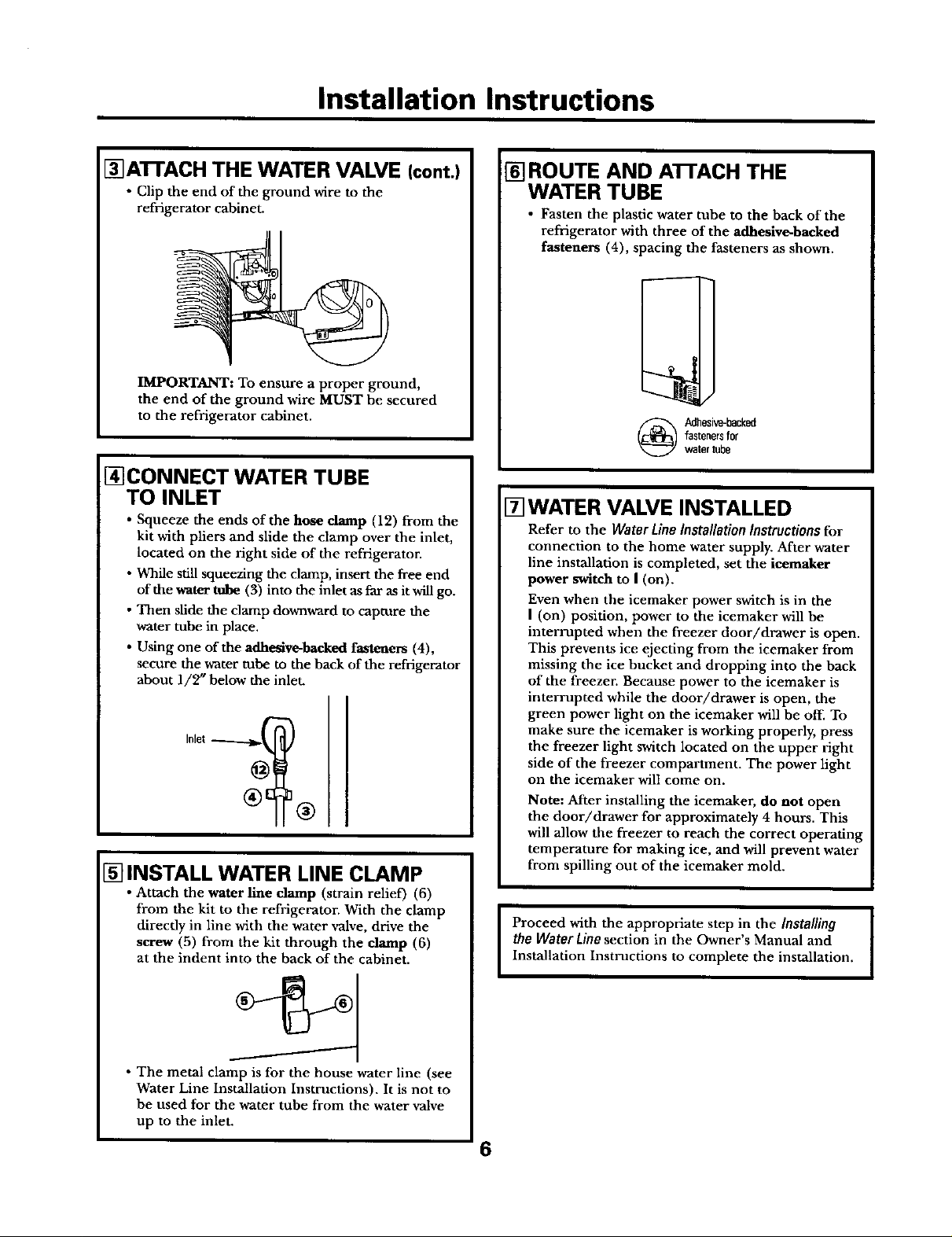
r_ATFACH THE WATER VALVE (cont.)
• Clip the end of the ground wire to the
refrigerator cabinet.
IMPORTANT: To ensure a proper ground,
the end of the ground wire MUST be secured
to the refrigerator cabinet.
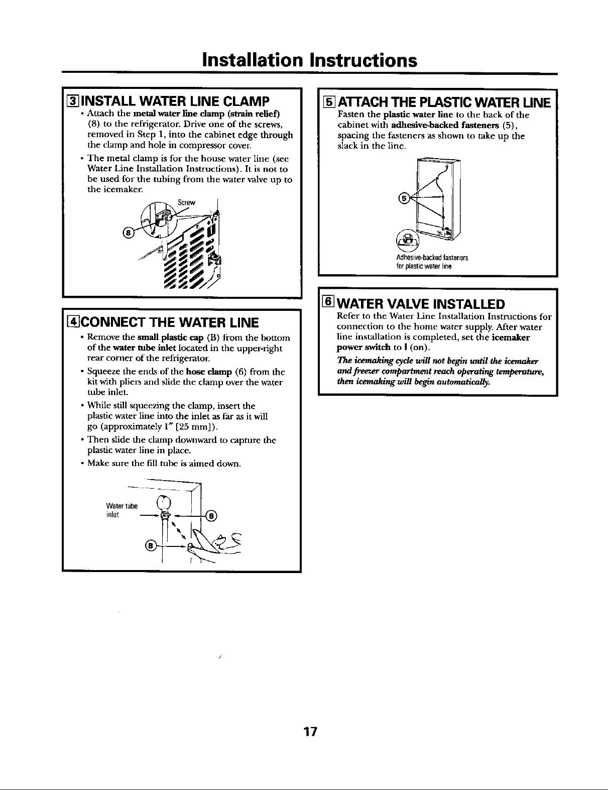
I_CONNECT WATER TUBE
TO INLET
• Squeeze the ends of the hose clamp (12) from the
kit with pliers and slide the clamp over the inlet,
located on the right side of the refrigerator.
• While still squeezing the clamp, insert the free end
of the water tube (3) into the inlet as far _ it will go.
• Then sfide the clamp downward to capture the
water tube in place.
• Using one of the adhesive-backed fasteners (4),
secure the water tube to the back of the refrigerator
about 1/2" below the inlet.
[] INSTALL WATER LINE CLAMP
[] ROUTE AND ATFACH THE
WATER TUBE
• Fasten the plastic water tube to the back of the
refrigerator with three of the adhesive-backed
fasteners (4), spacing the fasteners as shown.
fastenersfor
(_ Adhesive-backed
watertube
[] WATER VALVE INSTALLED
Refer to the Water Line Installation Instructions for
connection to the home water supply. After water
line installation is completed, set the ieemaker
power switch to I (on).
Even when the icemaker power switch is in the
I (on) position, power to the icemaker will be
interrupted when the freezer door/drawer is open.
This prevents ice ejecting from the icemaker from
missing the ice bucket and dropping into the back
of the freezer. Because power to the icemaker is
interrupted while the door/drawer is open, the
green power light on the icemaker will be off. To
make sure the icemaker is working properly, press
the freezer light switch located on the upper right
side of the freezer compartment. The power light
on the icemaker will come on.
Note: After installing the icemaker, do not open
the door/drawer for approximately 4 hours. This
will allow the freezer to reach the correct operating
temperature for making ice, and will prevent water
from spilling out of the icemaker mold.
from the kit to the refrigerator. With the clamp
direcdy in line with the water valve, drive the
screw (5) from the kit through the damp (6)
at the indent into the back of the cabinet.
i Attach the water line clamp (strain relief) (6)
The metal clamp is for the house water line (see
Water Line Installation Instructions). It is not to
he used for the water tube from the water valve
up to the inlet.
the Water Line section in the Owner's Manual and
Proceed with the appropriate step in the Installing
Installation Instructions to complete the installation,
6
Page 7
©
r/3
GEAppliances.com
Safety Information ......... 2
OperatingInstructions ...... 3
Before You Call For Service .... 4
Normal Sounds You May Hear . .3
Preparing for Vacation ....... 3
When You Should Set the
Icemaker Power Switch
to O (Off) ................. 3
Installation Instructions
Cold Water Line ......... 62-65
Fill Tube Templates ......... 66
Fill Tube Extension
Templates ................ 67
Icemaker [] ........... 10-13
Icemaker [] ........... 14-17
Icemaker [] ........... 18-21
Icemaker [] ........... 22-25
Icemaker [] ........... 26-29
Icemaker [] ........... 30-33
Icemaker [] ........... 34-37
Icemaker [] ........... 38-41
Icemaker [] ........... 42-45
Icemaker [] ........... 46-49
Icemaker [] ........... 50-53
Icemaker [] ........... 54-57
Icemaker [] ........... 58-61
Parts List ................ 6, 7
Removing Existing
Ice Cube Tray Holder ........ 8
Repositioning or Removing
the Freezer Shelf ............ 9
Kit IM-6
Thiskitfitsmostmodelscalling
for UK-KIT-I,UK-KIT-2,UK-KIT-4,
andallmodelscallingfor KitIM-1,
IM-2,IM-3,IM-4orIM5SS.Ifyou
arereplacinganicemakerwith
KitIM-1orIM-2,seepage&
Zrousse
Machine fi glagons
Lasectionfrangaisecommencei_Inpage69
Equipo de Accesorios
Mfiquina de Hielos
Lasecci6nonospo_ol empiezaonlap_gina 161
Consumer Support
Consumer Support.. Back Cover
Warranty ................. 68
197D4774PO03 49-60285 08-03 JR _k
Page 8
IMPORTANTSAFETYINFORMATION.
READALLINSTRUCTIONSBEFOREUSING.
SAFETYPRECAUTIONS
FORYOURSAFE'/'_.
Do not place fingers or hands in the automatic
icemaking mechanism while the refrigerator is
plugged in, This will help protect you from
possible injury.
READANDFOLLOWTHISSAFETYINFORMATIONCAREFULLY.
READAND SAVETHESEINSTRUCTIONS
It will also prevent interference with moving
parts of the ejector mechanism and the heating
element that releases the cubes, located on the
bottom of the icemaker.
•
Page 9
About the automatic icemaker. ptia,,,,om
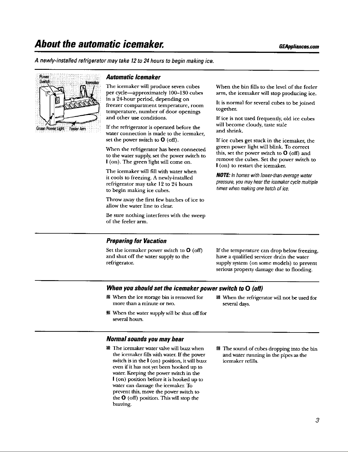
A newly-installed refrigerator may take 12 to 24 hours to begin making ice.
: _i Automatic Icemaker
The icemaker wiU produce seven cubes
in a 24-hour period, depending on
freezer compartment temperature, room
temperature, number of door openings
and other use conditions.
per cycle--approximately 100-130 cubes
i If the refrigerator is operated before the
.................. water connection is made to the icemaker,
set the power switch to O (off).
When the refrigez-ator has been connected
to the water supply, set the power switch to
I (on). The green light will come on.
The icemaker will fill with water when
it cools to freezing. A newly-installed
refrigerator may take 12 to 24 hours
to begin making ice cubes.
Throw away the first few batches of ice to
allow the water line to clear.
When the bin fills to the level of the feeler
arm, the icemaker will stop producing ice.
It is normal for several cubes to be joined
together.
If ice is not used frequently, old ice cubes
will become cloudy, taste stale
and shrink.
If ice cubes get stuck in the icemaker, the
green power light will blink. To correct
this, set the power switch to 0 (off) and
remove the cubes. Set the power switch to
I (on) to restart the icemaker.
NOTE:In homes with lower-than-averagewater
pressure,youmay hear theicemaker cyclemultiple
times whenmaking onebatch of ice.
Be sure nothing interferes with the sweep
of the feeler arm.
Preparing for Vacation
Set the icemaker power switch to 0 (off)
and shut off the water supply to the
refrigerator.
If the temperature can drop below freezing,
have a qualified servicer drain the water
supply system (on some models) to prevent
serious property damage due to flooding.
When you should set the icemaker power switch to 0 (off)
m When the ice storage bin is removed for M When the refrigerator will not be used for
more than a minute or two. several days.
m When the water supply will be shut off for
several hours.
Normal sounds you may hear
W The icemaker water valve will buzz when
the icemaker fills with water, ff the power
switch is in the I (on) position, it will buzz
even if it has not yet been hooked up to
water. Keeping the power switch in the
I (on) position before it is hooked up to
water can damage the icemaker. To
prevent this, move the power switch to
the O (off) position. This will stop the
buzzing.
The sound of cubes dropping into the bin
and water running in the pipes as the
icemaker refills.
3
Page 10
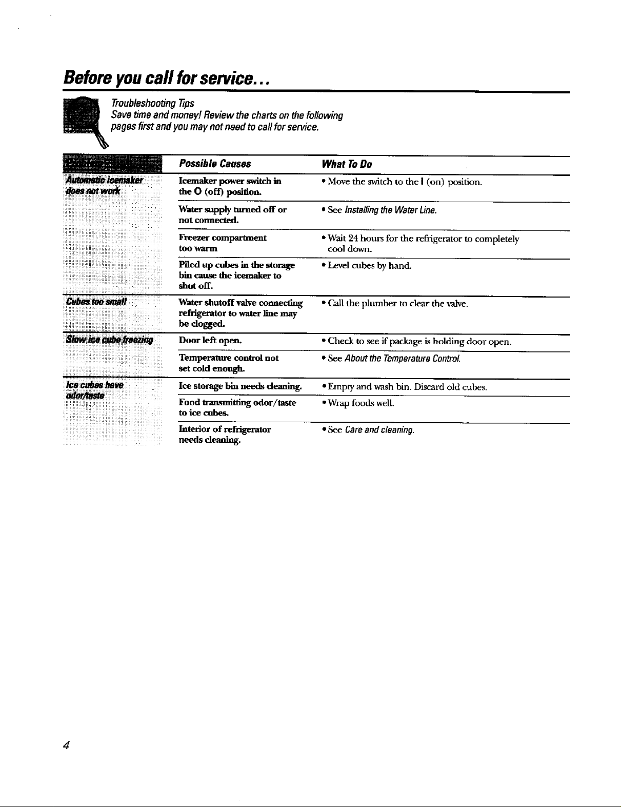
Beforeyoucall forservice...
Troubleshooting 77ps
Save _me and money/Review the charts on the following
pages first and you ma}/ not need to call for service.
Possible Causes What To Do
Icemaker power switch in * Move the switch to the I (on) position.
the 0 (off) position.
Water supply turned off or *SeelnstallingtheWaterUne.
not connected.
Freezer compartment *'Wait 24 hours for the refrigerator to completely
too warm cool down.
Piled up cobes in the storage • Level othes by hand.
bin cause the icemaker to
shut off.
_mmll Water shutoff valve connecting * Call the plumber to clear the valve.
refrig_ator to water line may
be dogged.
Door left open. • Check to see if package is holding door open.
Temperature control not • See About the TemperatureControl.
setcold enough.
icecU/Je_ Ice smxagebin needs cleaning. • Empty and wash bin. Discard old cubes,
m/_/Zaste
Food transmitting odor/taste • Wrap foods well.
to ice cube&
Interior of refrigerator • See Care and cleaning.
needs cleaning.
4
Page 11
Installation
IM-6 Icemaker Kit
Instructions
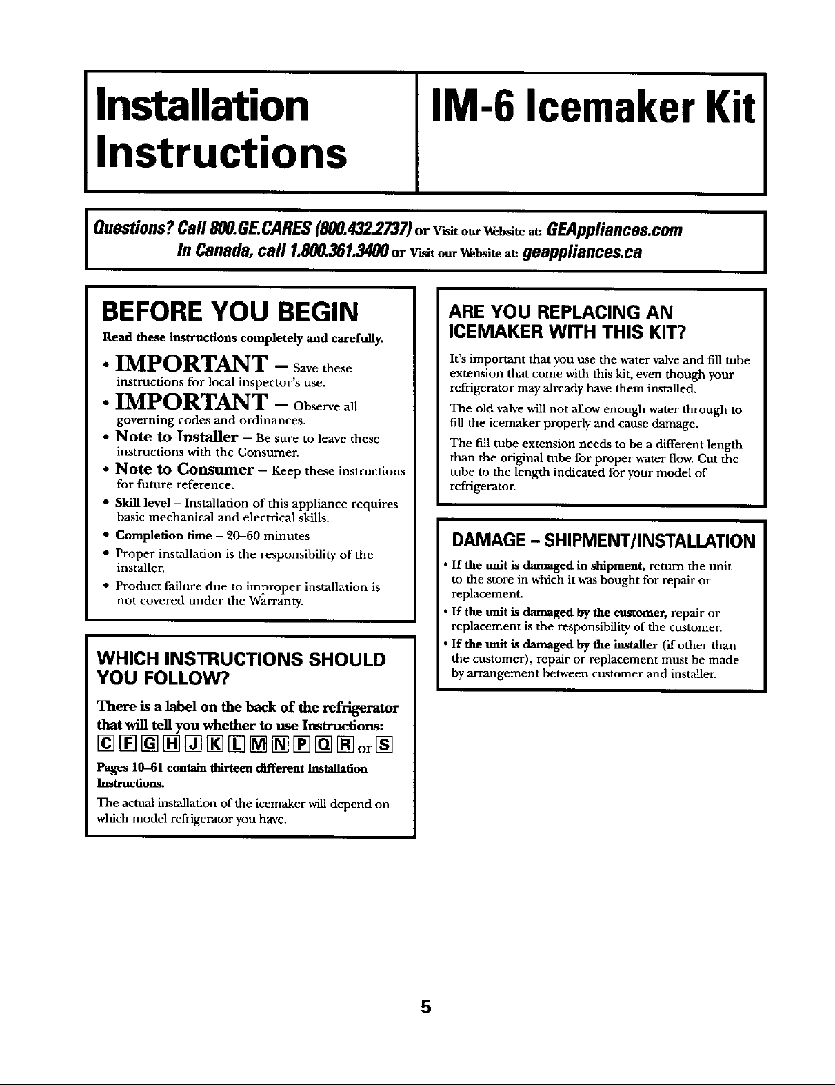
l Questions?Call 800.GECARES(800.432.2737)orv_t ourw_ at:GEAppliances.com
In Canada, call 1.800.361.3400or visito,_W_te a_geappliances.ca
BEFORE YOU BEGIN
Read these insO'uctions completely and carefully.
• IMPORTANT - Savethese
instructions for local inspector's use.
• IMPORTANT - Observeall
governing codes and ordinances.
• Note to Installer - Be sure to leave these
instructions with the Consumer.
• Note to Consumer - Keep these instructions
for future reference.
• Skill level - Installation of this appliance requires
basic mechanical and electrical skills.
• Completion time - 20-60 minutes
• Proper installation is the responsibility of the
installer.
• Product failure due to improper installation is
not covered under the Warranty.
WHICH INSTRUCTIONS SHOULD
YOU FOLLOW?
There is a label on the back of the refrigerator
that will tell you whether to use Instructions:
ARE YOU REPLACING AN
ICEMAKER WITH THIS KIT?
It's important that you use the water valve and fill tube
extension that come with this kit, even though your
refrigerator may already have them installed.
The old valve will not allow enough water through to
fill the icemaker properly and cause damage.
The fill tube extension needs to be a different length
than the original tube for proper water flow. Cut the
tube to the length indicated for your model of
refrigerator.
DAMAGE - SHIPMENT/INSTALLATION
• If the unit is damaged in shipment, return the unit
to the store in which itwas bought for repair or
replacement.
• If the unit is damaged by the customer, repair or
replacement is the responsibility of the customer.
• If the unit is damaged by the installer (if other than
the customer), repair or replacement must be made
by arrangement between customer and installer.
Pages 10-61 contain thirteen diffe_nt Installation
Instructions.
The actual installation of the icemaker will depend on
which model refrigerator you have.
5
Page 12
Installation Instructions
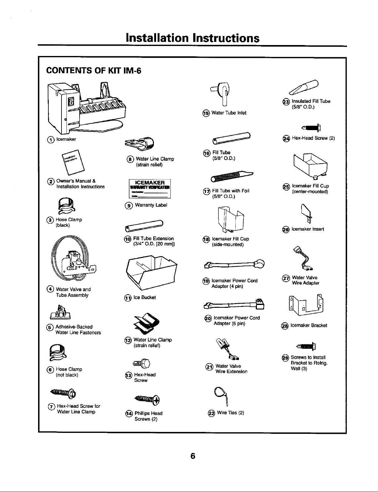
CONTENTS OF KIT IM-6
_) Insulated FillTube
(5/8" O.D.)
_) Water Tube Inlet
(_) Icemaker
Owner's Manual &
® .
Installatmn Instructions
(_) Hose Clamp
(black)
Q
(_) Water Valve and
Tube Assembly
m%
Adhesive-Backed
® .
Water Line Fasteners
(_) Hose Clamp
(not black)
(_ Water Line Clamp
(strain relief)
ICEMAKER ]
@ Warranty Label
(_ Fill Tube Extension
(3/4" O,D. [20 ram])
(_) Ice Bucket
@ Water Line Clamp
(strain relief)
_) Hex-Head
Screw
_) FillTube
(5/8"O.D.)
(_ FillTube with Foil
(5/8" O.D.)
©
Icemaker Fill Cup
_) (side-mounted)
(_ Icemaker Power Cord
Adapter (4 pin)
_ Icemaker Power Cord
Adapter (6 pin)
\
(_) Water Valve
Wire Extension
Hex-Head Screw (2)
_) Icemaker FillCup
(center-mounted)
_ Icemaker Insed
(_ Water Valve
Wire Adapter
_ Icemaker Bracket
_ Screws to Install
Bracketto Refrig.
Wall (3)
'==¢
(_) Hex-Head Screw for
Water Line Clamp
_) Phillips Head
Screws (2)
Wire "nes(2)
6
Page 13
Installation Instructions
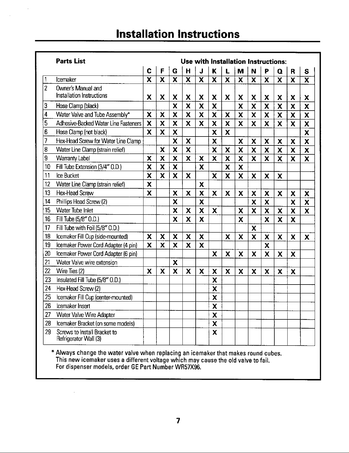
Parts List Use with Installation Instructions:
1 Icemaker X X X X X X X X X X X X X
2 Owner'sManualand
Installation Instructions X X X X X X X X X X X X X
3 HoseClamp(black) X X X X X X X X X X
4 WaterValveand TubeAssembly* X X X X X X X X X X X X X
5 Adhesive-BackedWater LineFasteners X X X X X X X X X X X X X
6 HoseClamp(notblack) X X X X X X
7 Hex-HeadScrewfor Water LineClamp X X X X X X X X X
8 Water LineClamp(strainrelief) X X X X X X X X X X X
9 Warranty Label X X X X X X X X X X X X X
10 Fill TubeExtension(3/4" O.D.) X X X X X X
11 IceBucket X X X X X X X X X X
12 Water LineClamp(strainrelief) X X
13 Hex-HeadScrew X X X X X X X X X X X X
;14 PhillipsHeadScrew (2) X X X X X X
'15 Water Tubelnlet X X X X X X X X X X
16 FillTube(5/8" 0.D,) X X X X X X X
17 FillTubewith Foil(5/8" O.D.) X
18 IcemakerFilICup(side-mounted) X X X X X X X X X X X X
19 IcemakerPowerCordAdapter(4pin) X X X X X X
20 IcemakerPowerCordAdapter(6pin) X X X X X X X
I
121 Water Valvewire extension X
22 WireSes(2) X X X X X X X X X X X X
23 InsulatedFillTube(5/8' O,D,) X
24 Hex-HeadScrew(2) X
25 IcemakerFill Cup(center-mounted) X
26 IcemakerInsert X
27 Water ValveWire Adapter X
28 IcemakerBracket(on somemodels) X
29 Screwsto Install Bracketto X
RefrigeratorWall (3)
* Always changethe water valvewhen replacing an icemakerthat makes round cubes.
This new icemaker uses a different voltage which may cause the old valve to fail.
Fordispenser models, order GEPart Number WR57X96.
7
Page 14
Installation Instructions
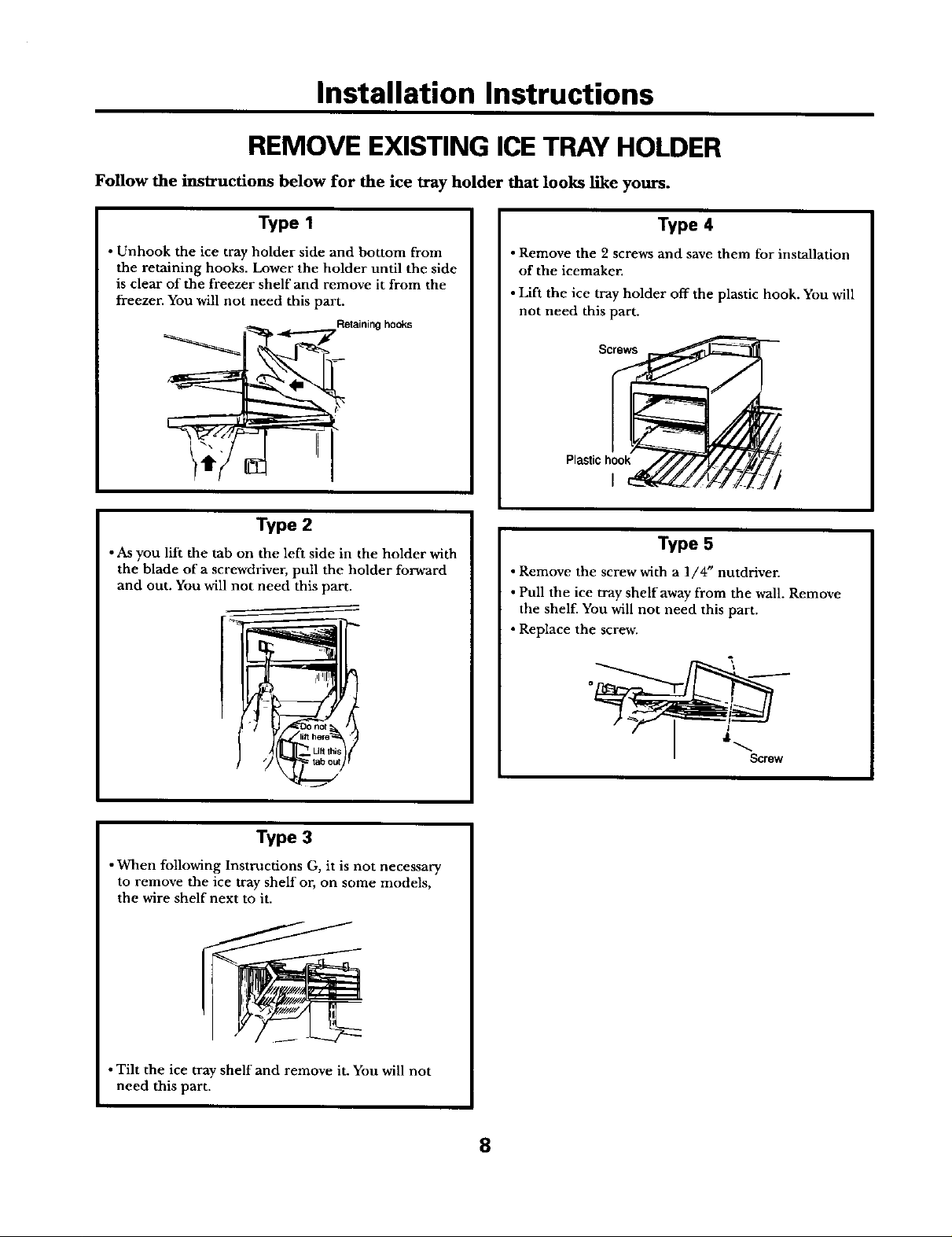
REMOVE EXISTING ICE TRAY HOLDER
Follow the instructions below for the ice tray holder that looks like yours.
Type I
• Unhook the ice tray holder side and bottom from
the retaining hooks. Lower the holder until the side
is clear of the freezer shelf and remove it from the
freezer. Yon will not need this part.
Retaining hooks
II
Type 2
• As you lift the tab on the left side in the holder with
the blade of a screwdriver, pull the holder forward
and out. You will not need this part.
Type 4
• Remove the 2 screws and save them for installation
of the icemaker.
• Lift the ice tray holder off the plastic hook. You will
not need this part.
Screws
Plastichook
I
Type 5
• Remove the screw with a 1/4" nutdriver.
• Pull the ice tray shelf away from the wall. Remove
the shelf. You will not need this part.
• Replace the screw.
Type 3
•When following Instructions G, it is not necessary
to remove the ice tray shelf or, on some models,
the wire shelf next to it.
• Tilt the ice tray shelf and remove it. You will not
need this part.
8
Page 15
Installation Instructions
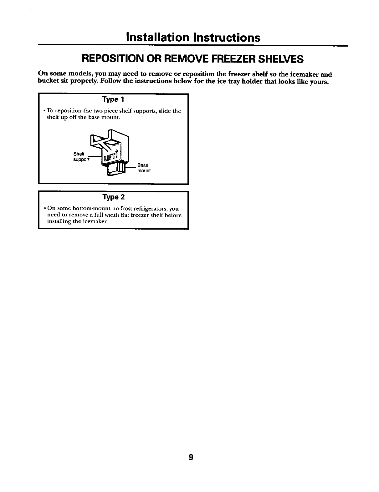
REPOSITION OR REMOVE FREEZER SHELVES
On some models, you may need to remove or reposition the freezer shelf so the icemaker and
bucket sit properly. Follow the instructions below for the ice tray holder that looks like yours.
Type 1
• To reposition the two-piece shelf supports, slide the
shelf up off the base mount.
Shelf
support
Type 2
• On some bottom-mount no-frost refrigerators, you
need to remove a full width flat freezer shelf before
installing the icemaker.
Base
mount
9
Page 16
Installation Instructions
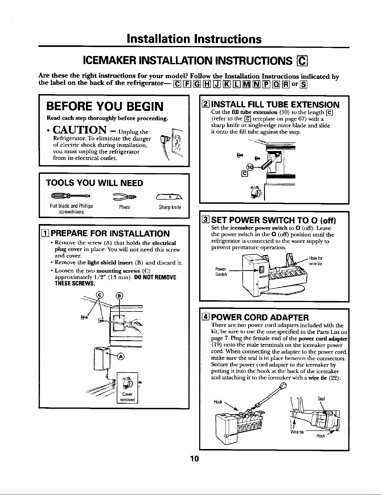
ICEMAKER INSTALLATION INSTRUCTIONS []
Are these the right instructions for your model? Follow the Installation Instructions indicated by
the label on the back of the refrigerator-- [] [] [] [] [] [] [] [] [] [] [] [] or []
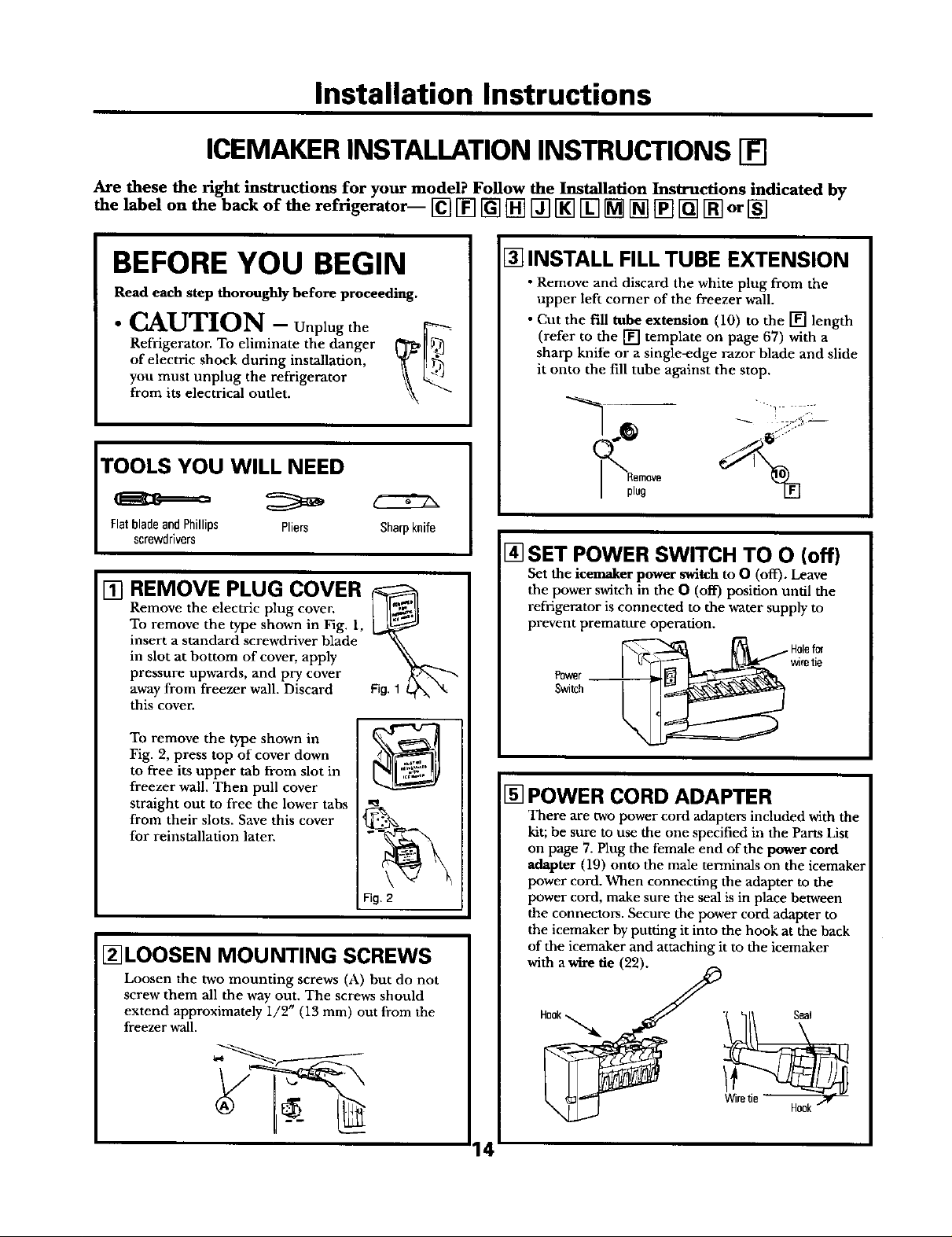
BEFORE YOU BEGIN
Read each step thoroughly before proceeding.
Refrigerator. To eliminate the danger
of electric shock during installation,
° _M_kUTION- Unplug the _
you must unplug the refrigerator
from its electrical outlet.
TOOLS YOU WILL NEED
FlatbladeandPhillips Pliers
screwdrivers
[] PREPARE FOR INSTALLATION
• Remove the screw (A) that holds the electrical
plug cover in place. You will not need this screw
and cover.
• Remove the light shield insert (B) and discard it.
• Loosen the two mounting screws (C)
approximately 1/2" (13 mm). DO NOT REMOVE
TNESESCREWS.
Sharpknife
[] INSTALL FILL TUBE EXTENSION
Cut the f'dl tube extension (10) to the length []
(refer to the [] template on page 67) with a
sharp knife or single-edge razor blade and slide
it onto the fill tube against the stop.
I
I
[] SET POWER SWITCH TO O (off)
Set the icemaker power switch to 0 (off). Leave
the power switch in the 0 (off) position until the
refrigerator is connected to the water supply to
prevent premature operation.
Switch
Foyer _ wiretie
[] POWER CORD ADAPTER
There are two power cord adapters included with the
kit; be sure to use the one specified in the Parts List on
page 7. Plug the female end of the power cord adapter
(19) onto the male terminals on the icemaker power
cord. When connecting the adapter to the power cord,
make sure the seal is in place between the connectors.
Secure the power cord adapter to the icemaker by
putting it into the hook at the back of the icemaker
and attaching it to the icemaker with a wire tie (22).
Hook
10
Page 17
Installation Instructions
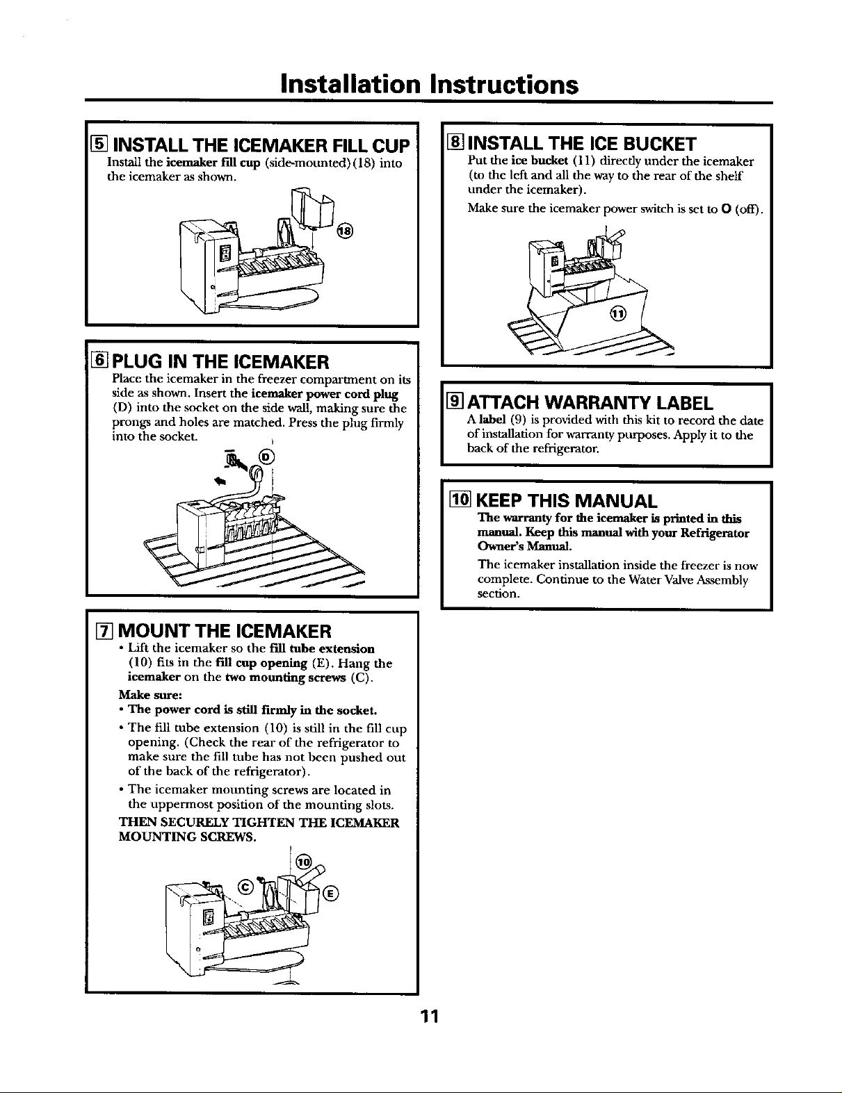
[] INSTALL THE ICEMAKER FILL CUP
Install the icemaker f'dl cup (side-mounted) (18) into
the icemaker as shown.
[] PLUG IN THE ICEMAKER
Place the icemaker in the freezer compartment on its
side as shown. Insert the icemaker power cord plug
(D) into the socket on the side wall, making sure the
prongs and holes are matched. Press the plug firmly
into the socket, b
[] INSTALL THE ICE BUCKET
Put the ice bucket (11 ) directly under the icemaker
(to the left and all the way to the rear of the shelf
under the icemaker).
Make sure the icemaker power switch is set t_ O (off).
A label (9) is provided with this kit to record the date
of installation for warranty purposes. Apply it to the
[_ ATTACH WARRANTY LABEL
back of the refrigerator.
[] KEEP THIS MANUAL
The warranty for the icemaker is printed in this
manual. Keep this manual with your Refrigerator
Owner's Manual.
The icemaker installation inside the freezer is now
complete. Continue to the Water Valve Assembly
section.
[] MOUNT THE ICEMAKER
• Lift the icemaker so the f'dl tube extension
(10) fits in the f'dl cup opening (E). Hang the
icemaker on the two mounting screws (C).
Make sure:
• The power cord is still firmly in the socket.
• The fill tube extension (10) is still in the fill cup
opening. (Check the rear of the refrigerator to
make sure the fill tube has not been pushed out
of the back of the refrigerator).
• The icemaker mounting screws are located in
the uppermost position of the mounting slots.
THEN SECURELY TIGHTEN THE ICEMAKER
MOUNTING SCREWS.
11
Page 18
Installation Instructions
WATER VALVE ASSEMBLY INSTALLATION INSTRUCTIONS []
Are these the right instructions for your model? Follow the Installation Instructions indicated by
the label on the back of the refrigerator-- [] [] [] [] [] [] [] [] [] [] [] [] or []
BEFORE YOU BEGIN
Read each step thoroughly before proceeding.
•CAUTION - Unplug the
Refrigerator. To eliminate the danger _]_
of electric shock during installation, it I
you must unplug the refrigerator from \\
its electrical outlet.
TOOLS YOU WILL NEED
FlatbladeandPhillips Pliers
screwdrivers
5116"Nutdriver
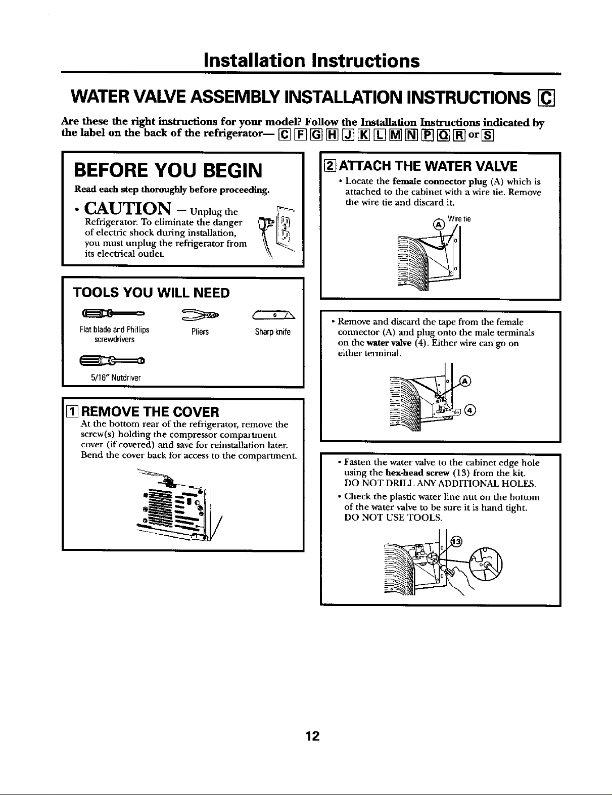
[] REMOVE THE COVER
At the bottom rear of the refrigerator, remove the
screw(s) holding the compressor compartment
cover (if covered) and save for reinstallation later.
Bend the cover back for access to the compartment.
Sharpknife
[] AI-rACH THE WATER VALVE
• Locate the female connector plug (A) which is
attached to the cabinet with a wire tie. Remove
the wire tie and discard it.
Wiretie
• Remove and discard the tape from the female
connector (A) and plug onto the male terminals
on the water valve (4). Either wire can go on
either terminal.
• Fasten the water valve to the cabinet edge hole
using the hex-head screw (13) from the kit.
DO NOT DRILL ANYADDITIONAL HOLES.
• Check the plastic water line nut on the bottom
of the water valve to be sure it is hand tight.
DO NOT USE TOOLS.
12
Page 19
Installation Instructions
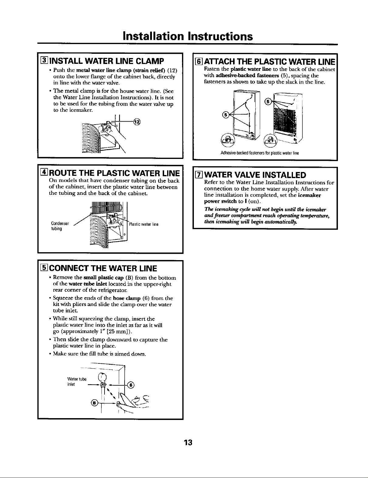
[] INSTALL WATER LINE CLAMP
• Push the metal water line damp (strain relief) (12)
onto the lower flange of the cabinet back, directly
in line with the water valve.
• The metal clamp is for the house water line. (See
the Water Line Installation Instructions). It is not
to be used for the tubing from the water valve up
to the icemaker.
[] ROUTE THE PLASTIC WATER LINE
On models that have condenser tubing on the back
of the cabinet, insert the plastic water line between
the tubing and the back of the cabinet.
Condenser
tubing
[] AI-rACH THE PLASTIC WATER LINE
Fasten the plastic water llne to the back of the cabinet
with adhesive-backed fasteners (5), spacing the
fasteners as shown m take up the slack in the line.
!
Adhesive-backedfastenersforplasticwaterline
[] WATER VALVE INSTALLED
Refer to the Water Line Installation Instructions foJ
connection to the home water supply. After water
line installation is completed, set the ieemaker
power switch to I (on).
The icemaking cycle will not begin until the icemaker
and freezer compartment reach operating temperature,
then icemaking will begin automatically.
[]CONNECT THE WATER LINE
• Remove the small plastic cap (B) from the bottom
of the water tube inlet located in the upper-right
rear corner of the refrigerator.
• Squeeze the ends of the hose clamp (6) from the
kit with pliers and slide the clamp over the water
tube inlet.
• While still squeezing the clamp, insert the
plastic water line into the inlet as far as it will
go (approximately 1" [25 ram]).
• Then slide the clamp downward to capture the
plastic water line in place.
• Make sure the fill tube is aimed down.
Watertube
inlet
13
Page 20
Installation Instructions
ICEMAKER INSTALLATION INSTRUCTIONS []
Are these the right instructions for your model? Follow the Installation Instructions indicated by
the label on the back of the refrigerator-- [] [] [] [] [] [] [] [] [] [] [] [] or []
BEFOREYOU BEGIN
Read each step thoroughly before proceeding.
Refrigerator. To eliminate the danger
of electric shock during installation,
° CAUTION- Unplug the _
you must unplug the refrigerator
from its electrical outlet.
TOOLS YOU WILL NEED
FlatbladeandPhillips Pliers
screwdrivers
Remove the electric plug cover.
To remove the type shown in Fig. 1,
insert a standard screwdriver blade
in slot at bottom of cover, apply
[] REMOVE PLUG COVER
pressure upwards, and pry cover
away from freezer wall. Discard
this cover.
[] INSTALL FILL TUBE EXTENSION
• Remove and discard the white plug from the
upper left corner of the freezer wall.
• Cut the Fill tube extension (10) to the [] length
(refer to the [] template on page 67) with a
sharp knife or a single-edge razor blade and slide
it onto the fill tube against the stop.
Sharpknife
[] SET POWER SWITCH TO O (off)
Set the icemaker power switch to O (off'). Leave
the power switch in the 0 (off) posidon until the
refrigerator is connected to the water supply to
prevent premature operation.
wiretie
Power
Switch
To remove the type shown in
Fig. 2, press top of cover down
to free its upper tab from slot in
freezer wall. Then pull cover
straight out to free the lower tabs
from their slots. Save this cover
for reinstallation later.
Fig.2
[_LOOSEN MOUNTING SCREWS
Loosen the two mounting screws (A) but do not
screw them all the way out. The screws should
extend approximately i/2" (13 mm) out from the
freezer wall.
[] POWER CORD ADAPTER
There are two power cord adapters included with the
kit; be sure to use the one specified in the Parts List
on page 7. Plug the female end of the power cord
adapter 09) onto the male terminals on the icemaker
power cord. When connecting the adapter to the
power cord, make sure the seal is in place between
the connectors. Secure the power cord adapter to
the icemaker by putting it into the hook at the back
of the icemaker and attaching it to the icemaker
with awire fie (22).
14
Page 21
Installation Instructions
[] INSTALL THE ICEMAKER FILL CUP
Install the icemaker f'dl cup (side-mounted) (18)
into the icemaker as shown.
@
[_PLUG IN THE ICEMAKER
Hold the icemaker in the freezer compartment as
shown. Insert the icemaker power cord plug (B)
into the socket on the rear wall, making sure the
prongs and holes are matched. Press the plug
firmly into the socket.
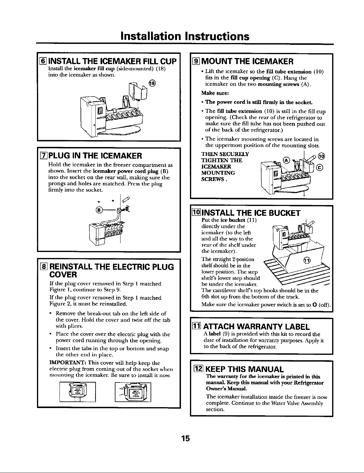
[] REINSTALL THE ELECTRIC PLUG
COVER
If the plug cover removed in Step 1 matched
Figalre 1, continue to Step 9.
If the plug cover removed in Step 1 matched
Figure 2, it must be reinstalled.
• Remove the break-out tab on the left side of
the cover. Hold the cover and twist off the tab
with pliers.
• Place the cover over the electric plug with the
power cord running through the opening.
• Insert the tabs in the top or bottom and snap
the other end in place.
IMPORTANT: This cover will help keep the
electric plug from coming out of the socket when
mounting the icemaker. Be sure to install it now.
®
[] MOUNT THE ICEMAKER
• Lift the icemaker so the fill tube extension (!0)
fits in the Fdl cup opening (C). Hang the
icemaker on the two mounting screws (A).
Make sure:
• The power cord is still firmly in the socket.
• The fill tube extension (10) is still in the fill cup
opening. (Check the rear of the refrigerator to
make sure the fill tube has not been pushed out
of the back of the refrigerator.)
• The icemaker mounting screws are located in
the uppermost position of the mounting slots.
TIGHTEN THE (_ @
ICF__AKF_ _)
MOUNTING
SCREWS.
THEN SECURELY
I_INSTALL THE ICE BUCKET
Put the ice bucket (11)
directly under the
icemaker (to the left
and all the way to the
rear of the shelf under
the icemaker).
The straight 2-position
shelf should be in the
lower position. The step
shelf's lower step should
be under the icemaker.
The cantilever shews top hooks should be in the
6th slot up from the bottom of the track.
Make sure the icemaker power switch is set to O (off).
ATTACH WARRANTY LABEL
A label (9) is provided with this kit to record the
date of installation for warranty purposes. Apply it
[]
to the back of the refrigerator.
[] KEEP THIS MANUAL
The warranty for the icemaker is printed in this
manual. Keep this manual with your Refrigerator
Owner's Manual.
The icemaker installation inside the freezer is now
complete. Continue to the Water Valve Assembly
section.
15
Page 22
Installation Instructions
WATER VALVE ASSEMBLY INSTALLATION INSTRUCTIONS []
Are these the right instructions for your model? Follow the Installation Instructions indicated by
the label on the back of the refrigerator-- [] [] [] [] [] [] [] [] [] [] [] [] or []
BEFORE YOU BEGIN
Read each step thoroughly before proceeding.
Refrigerator. To eliminate the danger IJ_)
of electric shock during installation,
"C_kUTION- Unplug the _
you must unplug the refrigerator
from its electrical oudet.
TOOLS YOU WILL NEED
FlatbladeandPhillips Pliers
screwdrivers
1/4" Nutdriver
I_REMOVE THE COVER
At the bottom rear of the refrigerator, remove the
screw(s) holding the compressor compartment
cover (if covered) and save for reinstallation later.
Bend the cover back for access to the compartment.
Sharpknife
[] ATTACH THE WATER VALVE
• Locate the female connector plug (C) which is
attached to the cabinet by a metal or plasdc clip.
Remove the clip by removing the screw. Save the
screw for moundng the water valve later. Discard
the clip. Metalor
plasticclip
• Plug the female comtector (C) onto the male
terminals on the water valve (4). Either wire
can go on either terminal.
16
• Fasten the water valve to the cabinet edge hole
using the hex-head screw that you removed at
the beginning of Step 2.
DO NOT DRILL ANY ADDITIONAL HOLES.
• Check the plastic water line nut on the bottom of
the water valve to be sure it is hand tight.
DO NOT USE TOOLS.
Page 23
Installation Instructions
r_INSTALL WATER LINE CLAMP
• Attach the metal water llne damp (strain relief)
(8) to the refrigerator. Drive one of the screws,
removed in Step 1, into the cabinet edge through
the clamp and hole in compressor cover.
• The metal clamp is for the house water line (see
Water Line Installation Instructions). It is not to
be used for the tubing from the water valve up to
the icemaker.
Screw
[_]CONNECT THE WATER LINE
• Remove the small plastic cap (B) from the bottom
of the water tube inlet located in the upper-right
rear corner of the refrigerator.
• Squeeze the ends of the hose damp (6) from the
kit with pliers and slide the clamp over the water
tube inlet.
• While still squeezing the clamp, insert the
plastic water line into the inlet as far as it will
go (approximately 1" [25 mm]).
• Then slide the clamp downward to capture the
plastic water line in place.
• Make sure the fill robe is aimed down.
[] ATTACH THE PLASTIC WATER LINE
Fasten the Plastic water line to the back of the
cabinet with adhesive-backed fasteners (5),
spacing the fasteners as shown to take up the
s]ack in the line.
/k
Adhesive-backedfasteners
forplasticwaterline
[] WATER VALVE INSTALLED
Refer to the Water Line Installation Instructions for
connection to the home water supply. After water
line installation is completed, set the icemaker
power switch to I (on).
The icemaking cycle will not be_n until the icemaker
and freezer compartment reach operating temperature,
then icemaking will begin automatically.
Water tube _-_
17
Page 24

Installation Instructions
ICEMAKER INSTALLATION INSTRUCTIONS []
Are these the right instructions for your model? Follow the Installation Instructions indicated by
the label on the back of the refrigerator-- [] [] [] [] [] [] [] [] [] [] [] [] or []
BEFOREYOU BEGIN
Read each step thoroughly before proceeding.
• CAUTION - Unplug the
Refrigerator. To eliminate the danger (_
you must unplug the refrigerator
of electric shock during installation, _
from its electrical outlet.
TOOLS YOU WILL NEED
FlatbladeandPhillips Pliers
screwdrivers
[] INSTALL WATER TUBE INLET
If the refrigerator already has a water tube inlet
on the back of the refrigerator, go to Step 2.
• Cut the fill tube (16) to the [] length (refer
to the [] template on page
single-edge razor blade.
66), with a sharp knife or a (_1_ _
• Slide the rill tube (16) onto
the water tube inlet (15).
• Find the small label in the
upper right hand corner on the back of the
refrigerator. Peel off the label.
• On the tube side of the
water tube inlet (15) there
is an adhesive backing.
Remove the adhesive
backing and slide the
tube into the hole near
the top at the back of the refrigerator.
Firmly press on the inlet to secure it.
Sharpknife
[] LOOSEN MOUNTING SCREWS
Loosen the two mounting screws (B) but do not
screw them all the way out. If your model does not
have the screws already in the freezer wall, look for
two plug buttons. Remove the plug buttons and
insert the two Phillips head screws (14). The screws
should extend approximately 1/2" (13 mm) out
from the freezer wall.
[] INSTALL FILL TUBE EXTENSION
• Remove and discard the white plug from the
upper left corner of the freezer wall.
• Cut the fill tube extension (10) to the [] length
(refer to the [] template on page 67) with a
sharp knife or a single-edge razor blade and slide
it onto the fill tube against the stop.
_irnove
plug
[] SET POWER SWITCH TO O (off)
Set the icemaker power switch to O (off). Leave
the power switch in the O (off) position undl the
refrigerator is connected to the water supply to
prevent premature operation.
[] REMOVE PLUG COVER
Remove the electric plug cover from
the left side wall of the freezer by
pulling the cover (A) straight out
while pressing the sides of the cover
to free its tabs from the slots.
Discard the cover.
_. / Holefor
Switch
18
Page 25

Installation Instructions
[] POWER CORD ADAPTER
There are two power cord adapters included with the
kit; be sure to use the one specified in the Parts List
on page 7. Plug the female end of the power curd
adapter (19) onto the male terminals on the icemaker
power cord. When connecting the adapter to the
power cord, make sure the seal is in place between
the connectors. Seolre the power cord adapter to
the icemaker by putting it into the hook at the back
of the icemaker and attaching it to the icemaker
with awire tie (22).
[] INSTALL THE ICEMAKER FILL CUP
Install the icemaker fill cup (side-mounted) (18)
into the icemaker as shown.
[] MOUNT ICEMAKER
• Lift the icemaker so the fill tube extension (10)
fits in the fill cup opening (C). Hang the
icemaker on the two mounting screws (A).
Make $11re:
• The power cord is still firmly in the socket.
• The fill tube extension (10) is still in the fill cup
opening. (Check the rear of the refrigerator to
make sure the fill tube has not been pushed out
of the back of the refrigerator.)
• The icemaker moundng screws are located in
the uppermost position of the mounting slots.
THEN TIGHTEN THE ICEMAKER MOUNTING
SCREWS SECURELY.
[]PLUG IN THE ICEMAKER
Hold the icemaker in the freezer compartment as
shown. Insert the ieemaker power cord plug (D)
into the socket, making sure the prongs and holes
are matched. Press the plug firmly into the socket.
I
[] INSTALL THE ICE BUCKET
Put the ice bucket (11)
directly under the
icemaker (to the left and
all the way to the rear of
the shelf under the
icemaker).
Make sure the icemaker
power switch is set to
0 (off).
A label (9) is provided with this kit to record the
date of installation for warranty purposes. Apply it
[_ ATTACH WARRANTY LABEL
to the back of the refrigerator.
[] KEEP THIS MANUAL
The warranty for the icemaker is printed in this
manual. Keep this manual with your Refrigerator
Owner's Manual.
The icemaker installation inside the freezer is now
complete. Continue to the Water Valve Assembly
section.
19
Page 26

Installation Instructions
WATER VALVE ASSEMBLY INSTALLATION INSTRUCTIONS []
Are these the right instructions for your model? Follow the Installation Instructions indicated by
the label on the back of the refrigerator-- [] [] [] [] [] [] [] [] [] [] [] [] or []
BEFORE YOU BEGIN
Read each step thoroughly before proceeding.
• CAUTION - Unplug the
Refrigerator. To eliminate the danger
of electric shock during installation, _ ]_
you must unplug the refrigerator \_ _k_
from its electrical oudet.
TOOLS YOU WILL NEED
FlatbladeandPhillips Pliers Sharpknife
screwdrivers
1/4" and5/16"Nutdrivers
[]REMOVE THE COVER
At the bottom rear of the refrigerator, remo_,e the
screw(s) holding the compressor compartment
cover (if covered) and save for reiustalladon later.
Bend the cover back for access to the compartment.
[] ATTACH THE WATER VALVE
• Locate the female connector plug (B).
• Plug the female connector (B) onto the male
terminals on the water valve wire extension (21).
Either wire can go on either terminal.
• Plug the female connector on the water valve wire
extension (21) onto the male _ on the
water valve (4). Either wire can go on either
terminal.
2O
• Fasten the water valve to the cabinet edge hole
using the hex-head screw (13) from the kit.
DO NOT DRILL ANY ADDITIONAL HOLES.
• Check the plastic water llne nut on the bottom of
the water valve to be sure it is hand fight. DO NOT
USE TOOLS.
Page 27

Installation Instructions
[] INSTALL WATER LINE CLAMP
• Attach the metal water line damp (strain relief)
(8) to the refrigerator. Drive the screw (7) from
the kit through the damp (8) at the indent into
the back of the cabinet.
• The metal clamp is for the house water line (see
the Water Line Installation Instructions). It is not
to be used for the tubing from the water valve up
to the icemaker.
[_]CONNECT THE WATER LINE
• Squeeze the ends of the hose clamp (3) or(6) from
the kit with pliers and slide the clamp over the
water tube inlet. (Use the black clamp (3) with
the black fill tube inlet, use the otber clamp (6)
with the other fill tube inlet.)
• While still squeezing the clamp, insert the
plastic water line into the inlet as far as it will
go (approximately 1" [25 mm]).
• Then slide the clamp downward to capture the
plastic water line in place.
• Make sure the fill tube is aimed down.
[] ATTACH THE PLASTIC WATER
LINE
Fasten the plastic water line to the back of the
cabinet with adhesive-backed fasteners (5),
spacing the fasteners as shown to take up the
slack in the line.
/k
-..,,
Adhesive-backedfasteners
for plasticwaterline
I-6qWATER VALVE INSTALLED
Refer to the Water Line Installation Instructions
for connection to the home water supply. After
water line installation is completed, set the
icemaker power switch to I (on).
The icemaking cycle will not begin until the icemaker
aml freezer compartment reach operating temperature,
then icemaking will begin automaticat_.
Watertube
inlet
21
Page 28

Installation Instructions
ICEMAKER INSTALLATION INSTRUCTIONS []
Are these the right instructions for your model? Follow the Installation Instructions indicated by
the label on the back of the refrigerator-- [] [] [] [] [] [] [] [] [] [] [] [] or []
NOTE: If you have refrigerator model TNS22 or TNX22, please refer to the installation
instructions for [] , instead of using the [] instructions.
BEFORE YOU BEGIN
Read each step thoroughly before proceeding.
Refrigerator. To eliminate the danger
of electric shock during installation,
" CdixUTION- Unplug the _
you must unplug the refrigerator
from its electrical outlet.
TOOLS YOU WILL NEED
FlatbladeandPhillips Pliers
screwdrivers
[] PREPARE FOR INSTALLATION
Remove and discard the white -_.
plug from the upper left
corner of the freezer wall.
[] INSTALL WATER TUBE INLET
• Locate the hole in the upper fight corner on
the back of the refrigerator and, using a knife,
clear the foil from the hole.
• Remove the gray insulation plug from the hole.
NOTE: It may be necessary to remove the screw
from the top right condenser mounting clip for
better access to the hole (see page 25, Step 4).
• Cut the fill tube (16) to the [] length (refer to
the [] template on page 66), with a sharp knife
or a single-edge razor blade.
!
Sharpknife
.6
v°
[] REMOVE PLUG COVER
• Remove the electric plug cover .-J_l
from the left side wall and discard it.
• Remove the screw and pull the
cover off. N%
/
[] LOOSEN MOUNTING SCREWS
Loosen the two mounting screws (A) but do not
screw them all the way out. The screws should
extend approximately 1/2" (13 mm) out from
the freezer wall.
[] SET POWER SWITCH TO O (off)
Set the icemaker power switch to 0 (off). Leave
the power switch in the O (off) position until the
refrigerator is connected to the water supply to
prevent premature operation.
Power __
S_vitch
wiretie
• Slide the f'fll tube (16) onto (_IIID _the water tube inlet (15).
• On the tube side of the water
tube inlet (15) there is an
adhesive backing. Remove
the backing. Slide the tube
of the refrigerator as
shown. Firmly press on J
the inlet to secure it.
22
Page 29

Installation Instructions
[] POWER CORD ADAPTER
There are two power cord adapters included with the
kit; be sure to use the one specified in the Parts List on
page 7. Plug the female end of the power cord adapter
(19) onto the male terminals on the icemaker power
cord. When connecting the adapter to the power
cord, make sure the seal is in place between the
connectors. Secure the power cord adapter to the
icemaker by putting it into the hook at the back of
the icemaker and attaching it to the icemaker with
awire lie (22).
[] INSTALL THE ICEMAKER FILL CUP
Install the icemaker fill cup (side-mounted) (18) into
the icemaker as shown.
[] MOUNT ICEMAKER
• Lift the icemaker so the fill tube (16) fits in the
f'dl cup opening (C). Hang the icemaker on the
two mounting screws (A).
Make sure:
• The power cord is still firmly in the socket.
• The fiU tube (16) is still in the fill cup opening.
(Check the rear of the refrigerator to make sure
the fill tube has not been pushed out of the back
of the refrigerator.)
• The icemaker mounting screws are located in
the uppermost position of the mounting slots.
THEN TIGHTEN THE ICEMAKER MOUNTING
SCREWS SECURELY.
[]PLUG IN THE ICEMAKER
Place the icemaker on its side as shown. Insert the
icemaker power cord plug (B) into the socket,
making sure the prongs and holes are matched.
Press the plug firmly into the socket.
I
¢
1-_ INSTALL THE ICE BUCKET
Put the ice bucket (11) in place under the icemaker.
Make sure the icemaker power switch is set to O (off).
ATTACH WARRANTY LABEL
A label (9) is provided with this kit to record the
date of installation for warranty purposes. Apply it
to the back of the refrigerator.
KEEP THIS MANUAL
[]
The warranty for the icemaker is printed in this
manual. Keep this manual with your Refrigerator
Owner's Manual.
The icemaker installation inside the freezer is now
complete. Continue to the Water Valve Assembly
section.
23
Page 30

Installation Instructions
WATER VALVE ASSEMBLY INSTALLATION INSTRUCTIONS []
Are these the right instructions for your model? Follow the Installation Instructions indicated by
the label on the back of the refrigerator-- [] [] [] [] [] [] [] [] [] [] [] [] or []
BEFOREYOU BEGIN
Read each step thoroughly before proceeding.
Refrigerator. To eliminate the danger I_
of electric shock during installation,
" _UTION- Unplug the _
you must unplug the refrigerator from
its electrical outlet.
TOOLS YOU WILL NEED
FlatbladeandPhillips Pliers
screwdrivers
1/4" and 5/16" Nutdriver
[] ATrACH THE WATER VALVE
• Locate the female connector plug (B).
Sharpknife
• Plug the female connector (B) onto the male
terminals on the water valve (4). Either wire
can go on either terminal.
• Fasten the water valve to the cabinet edge hole
using the hex-head screw (13) from the kit.
DO NOT DRILL ANY ADDITIONAL HOLES.
• Check the plastic water line nut on the bottom of
the water valve to be sure it is hand tight. DO NOT
USE TOOLS.
F271NSTALL WATER LINE CLAMP
• Attach the metal water line clamp (strain relief)
(8) to the refrigerator. Drive the screw (7) from
the kit through the clamp (8) at the indent into
the back of the cabinet.
• The metal clamp is for the house water line (see
the Water Line Installation Instructions). It is not
to be used for the tubing from the water valve up
to the icemaker.
24
Page 31

Installation Instructions
_]CONNECT THE WATER LINE
• Squeeze the ends of the hose clamp (3) from
the kit with pliers and slide the clamp over the
water tube inlet.
• While still squeezing the clamp, insert the
plastic water line into the inlet as tar as it will
go (approximately 1" [95 mm]).
• Then slide the clamp downward to capture the
plastic water line in place.
• Make sure the fill tube is aimed down.
• If the condenser moundng screw was removed,
secure the condenser to the refrigerator by
replacing the mounting clip and screw.
DO NOT OVER-TIGHTEN THE SCREW.
Watertube
inlet
[_A1-FACH THE PLASTIC
WATER LINE
Fasten the plastic water fine to the back of the
cabinet with adhesive-backed fasteners (5), spacing
the fasteners as shown to take up the slack in the
line. (It may be necessary to remove the screw from
the top right condenser mounting clip for better
access to the water tube inlet).
[] WATER VALVE INSTALLED
Refer to the Water Line Installation Instructions
for connection to the home water supply. After
water line installation is completed, set the
icemaker power switch to I (on).
The icemaking cycle will not begin until the icemaker
and f_ezer compartment reach operating temperature,
then icemaking will begin automatically.
) Adhesive-backedfasteners
forplasticwaterline
25
Page 32

Installation Instructions
ICEMAKER INSTALLATION INSTRUCTIONS []
Are these the right instructions for your model? Follow the Installation Instructions indicated by
the label on the back of the refrigerator-- [] [] [] [] [] [] [] [] [] [] [] [] or []
BEFORE YOU BEGIN
Read each step thoroughly before proceeding.
• CAUTION - Unphtg the
Refrigerator. To eliminate the danger rr,
of electric shock during installation, _ [_
you must unplug the refrigerator _fi-om its electrical oudet.
TOOLS YOU WILL NEED
FlatbladeandPhillips Pliers
scrawdtivers
1/4"and5/16"Nutdriveroradjustablewrench
[] REMOVE ICE CUBE TRAY SHELF
If your refrigerator has an installed ice cube tray
shelf, use a Phillips screwdriver to remove the two
screws. Remove the ice tray shelf. Install the
screws in the back two holes until the screw heads
are about 1/2" (13 mm) from the side wall of the
freezer. If your refrigerator was not originally
equipped with an installed ice cube tray shelf,
use the screws (14) that are supplied in the kit.
Place the shelf, flat side up, in the lower basket
with the sloped end at the back.
Partiallyreinstalltwo Removesticker
screwsinreartw_o _
Sharpknife
[] PREPARE THE REFRIGERATOR
Find the sticker located
on the back of the
refrigerator about
midway up on the right / Removesticker
hand side. Remove the
sticker and clear away o_
any foil tape from the 9
opening. Also remove
the sticker from the top Remov_
left corner of the insulationplug
freezer compartment.
Remove the gray insulation plug that fills the hole
through the cabinet.
[] INSTALL FILL TUBE
• Cut the Fill tube (16) to the []
on page 66) with a sharp knife
length (refer to the [_ template (_'_111_ _
or a single-edge razor blade.
• Slide the fill tube (16) onto the
water tube inlet (15 ).
• Cut the fill tube extension (10) to the [] length
(refer to the [] template on page 67) with a
sharp knife or a single-edge razor blade.
• Slide the Fill tube extension (10) completely over
the fill tube on the water tube inlet (15).
• On the tube side of the water
tube inlet (15) there is an O
adhesive backing. Remove the
backing and slide the tube into
the hole on the back of the
refrigerator as shown. Firmly
press on the inlet to secure it.
[] SET POWER SWITCH TO O (off)
Set the icemaker power switch to 0 (off). Leave
the power switch in the 0 (off) position until the
refrigerator is connected to the water supply to
prevent premature operation.
Po_er
Switch
26
wireRe
Page 33

Installation Instructions
[] INSTALL THE ICEMAKER FILL CUP
Install the icemaker fill cup (side-mounted) (18)
into the icemaker as shown.
@
ISIREMOVE PLUG COVER
Remove the electric plug cover
from the side wall of the freezer
compartment. Insert a standard
screwdriver blade into the slot in
the cover and twist the screwdriver,
opening the slot. The cover will
pop off. Discard this cover.
[] POWER CORD ADAPTER
There are two power cord adapters included with the
kit; be sure to use the one specified in the Parts List
on page 7. Plug the female end of the power cord
adapter (19) onto the male terminals on the icemaker
power cord. When connecting the adapter to the
power cord, make sure the seal is in place between
the connectors. Secure the power cord adapter to
the icemaker by putting it into the hook at the back
of the icemaker and attaching it to the icemaker
with awire tie (22).
[] MOUNT THE ICEMAKER
• Lift the icemaker so the fill tube extension (10)
fits in the fill cup opening (C). Hang the
icemaker on the two mounting screws (A).
Make sure:
• The power cord is still firmly in the socket.
• The fill tube extension (10) is still in the filI cup
opening. (Check the rear of the refrigerator to
make sure the fill tube has not been pushed out
of the back of the refrigerator.)
• The icemaker mounting screws are located in
the uppermost position of the mounting slots,
• Make sure the icemaker power switch is set
to 0 (off).
THEN TIGHTEN THE ICEMAKER MOUNTING
SCREWS SECURELY.
INSTALL THE ICE BUCKET
Place the ice bucket that came with your
refrigerator in the lowest position on the left side
of the freezer compartment.
ATI'ACH WARRANTY LABEL
A label (9) is provided with this kit to record the
date of installation for warranty purposes. Apply it
to the back of the refrigerator.
[] PLUG IN THE ICEMAKER
Place the icemaker on its
side as shown. Insert the
icemaker power cord plug
(A) into the socket on the
side wall, making sure the
prongs and holes are
matched. Press the plug
firmly into the socket.
[] KEEP THIS MANUAL
The warranty for the icemaker is printed in this
manual. Keep this manual with your Refrigerator
Owner's Manual.
The icemaker installation inside the freezer is now
complete. Continue to the Water Valve Assembly
section.
27
Page 34

Installation Instructions
WATER VALVE ASSEMBLY INSTALLATION INSTRUCTIONS []
Are these the right instructions for your model? Follow the Installation Instructions indicated by
the label on the back of the refrigerator-- [] [] [] [] [] [] [] [] [] [] [] [] or []
BEFORE YOU BEGIN
Read each step thoroughly before proceeding.
CAUTION - Unplug the
Refrigerator. To eliminate the danger _'j_ [_,_
of electric shock during installation, "_ _
you must unplug the refrigerator from
its electrical oudet.
TOOLS YOU WILL NEED
FlatbladeandPhillips
screwdrivers
1/4" Nutdriver
[_REMOVE THE ACCESS COVER
Remove the rear access cover. This requires
removing six screws which attach the cover to the
back of the refrigerator case. Use a 5/16" socket or
an adjustable wrench. Be sure to save the screws as
the access cover must be reinstalled later to ensure
your refrigerator will function properly.
Pliers Sharpknife
5/16"Socketaradjustablewrench
[] ATTACH THE WATER VALVE
• Locate the female connector plug (A).
• Plug the female connector (A) onto the male
terminals on the water valve (4). Either wire
can go on either terminal.
• Fasten the water valve to the cabinet by driving
the hex-head screw (13).
DO NOT DRILL ANYADDITIONAL HOLES
NOTE: There may be some internal refrigerant
tubing that will need to be moved slightly in
order to provide enough room to install the
water valve.
• Check the plastic water line nut on the bottom
of the water valve to be sure it is hand tight.
DO NOT USE TOOLS.
28
Page 35

Installation Instructions
[] INSTALL WATER LINE CLAMP
• Push the metal water line clamp (strain relief) (19)
onto the lower flange of the cabinet back, directly
in line with the water valve.
• The metal clamp is for the house water line. (See
the Water Line Installation Instructions). It is not
to be used for the tubing from the water valve up
to the icemaker.
I_CONNECT THE WATER LINE
• Ensure that you have sufficient length of plastic
tube to extend well into the water tube inlet.
Cut off excess tubing.
• Squeeze the ends of the hose damp (3) from
the kit with pliers and slide the clamp over the
water uthe inlet.
• While still squeezing the clamp, insert the
plastic water line into the inlet as t_tr as it will
go (approximately 1" [25 ram]).
• Then slide the clamp downward to capture the
plastic water line in place.
• Make sure the fill tube is aimed down.
[]ATTACH THE PLASTIC WATER
LINE
Route the plastic water line along the back of the
refrigerator to the icemaker hole in the case back.
Use three of the adhesive-backed fasteners (5) to
secure the tube to the case back.
fastenersfor plastic
@ Adhesive-backed
waterline
[] WATER VALVE INSTALLED
Refer to the Water Line Installation Instructions for
connection to the home water supply. After water
line installation is completed, set the icemaker
power switch to I (on).
The icemaking cycle will not begin until the icemaker
and freezer compartment reach operating temperature,
then icemaking will begin automaticatty.
Watertube
2
29
Page 36

Installation Instructions
ICEMAKER INSTALLATION INSTRUCTIONS []
Are these the right instructions for your model? Follow the Installation Instructions indicated by
the label on the back of the refrigerator-- [] [] [] [] [] [] [] [] [] [] [] [] or []
BEFORE YOU BEGIN
Read each step thoroughly before proceeding.
Refrigerator. To eliminate the danger
of electric shock during installation,
° C_UTION- Unplug the _
you must unplug the refrigerator
from its electrical outlet.
TOOLS YOU WILL NEED
FlatbladeandPhillips Pliers
screwdrivers
[] PREPARE FOR INSTALLATION
• Remove the upper outlet cover with a flat-blade
screwdriver.
• If there is already an icemaker bracket (28) installed in
the freezer, remove the two screws holding on the cover.
Remove and discard the cover. Go to Step 5.
Sharpknife
[]INSTALL FILL TUBE
• Slide the instdated fill tube (23)
ontotho.t et,l`5),
making sltre that the open side
of the fill tube faces up.
• Go to the back of the
refrigerator. On the tube side
of the water tube inlet (1,5) there is an adhesive
backing. Remove the adhesive backing and slide
the tube into the hole near the top at the back of
the refrigerator. Firmly press on the inlet to secure
it to the refrigerator.
[] INSTALL MOUNTING BRACKET
• Remove the three small plug buttons on the rear
wall of the freezer and replace them with three
screws (29) supplied with the icemaker kit. Do
not screw them all the way in. The screws should
extend approximately 1/4" (6 mm) out from
the freezer wall.
• Install the ieemaker _t N_
_x
121REMOVE FILL HOLE PLUG
• Remove and discard the large white plug from the
rear freezer wall. Pull out the gray insulation plug
and remove any debris.
Remov,I
plug
bracket (28) by hanging _t,,,i['_N.___-
it from the three screws
that were just installed.
Tighten the three screws
securely.
[] SET POWER SWITCH TO 0 (off)
Set the icemaker power switch to 0 (off). Leave
the power switch in the 0 (off) position until the
refrigerator is connected to the water supply to
prevent premature operadon.
Power
S_tch
. wiretie
30
©
Holefor
Page 37

Installation Instructions
[] POWER CORD ADAPTER
There are two power cord adapters included with the
kit; be sure to use the one specified in the Parts List
on page 7. Plug the female end oftbe power cord
adapter (20) onto the male terminals on the icemaker
power cord. When connecting the adapter to the
power cord, make sure the seal is in place between
the connectors. Secure the power cord adapter to
the icemaker by putting it into the hook at the back
of the icemaker and attaching it to the icemaker with
a wire tie (22).
@
I_INSTALL THE ICEMAKER FILL
CUP AND INSERT
Install the icemaker fill cup (center-mounted) (25)
and icemaker insert (26) into the icemaker as shown.
MOUNT THE ICEMAKER
• Lift the icemaker up and hang it on the icemaker
bracket (28). Make sure the insulated fill tube (23)
goes into the fill cup (25) opening. To secure the
icemaker to the bracket (28), use two screws (24)
and install as shown.
Make sure:
• The power cord is still firmly in the socket.
• The insulated f'dl tube (23) extends into the fill
cup opening at the back of the icemaker. (Check
the rear of the refrigerator to make sure that the
fill tube has not
pushed out the
back of the
refrigerator).
• The icemaker
is secured to
the bracket.
[]INSTALL THE ICE BUCKET
Place the ice bucket (11) under the icemaker.
Make sure the icemaker power switch is set to O (off)
[] PLUG IN THE ICEMAKER
Holding the icemaker in place, insert the power
cord plug into the socket, making sure that the
prongs and holes are matched. Press the phlg firmly
into the socket. Lock the plug in place by clipping
the restraints onto each side of the plug. Make sure
the restraints click into place.
][_ ATTACH WARRANTY LABEL I
A label (9) is provided with this kit to record the date I
of installation for warranty purposes. Apply it to the I
back of the refrigerator. I
I
[] KEEP THIS MANUAL
The warranty for the icemaker is printed in this
manual. Keep this manual with your Refrigerator
Owner's Manual.
The icemaker installation inside the freezer is now
complete. Continue to the Installing the Water
Valve Assembly section.
31
Page 38

Installation Instructions
WATER VALVEASSEMBLY INSTALLATION INSTRUCTIONS []
Are these the right instructions for your model? Follow the Installation Instructions indicated by
the label on the back of the refrigerator-- [] [] [] [] [] [] [] [] [] [] [] [] or []
BEFOREYOU BEGIN
Read each step thoroughly before proceeding.
Refrigerator. To eliminate the danger
of electric shock during installation,
° CAUTION- Unplug the _
you must unplug the refrigerator
from its electrical outlet.
TOOLS YOU WILL NEED
FlatbladeandPhillips Pliers
screwdrivers
1/4" and5/16"Nutdrivers.or adjustablewrench
[] REMOVE THE COVER
Use a nutdriver or an adjustable va-ench to remove
the compressor compartment access cover. This
requires removing six screws which attach the cover
to the back of the refrigerator case.
Be sure to save the screws as the access cover must
be reinstalled later to ensure your refrigerator will
function properly.
Sharpknife
[] ATTACH THE WATER VALVE
• Locate the 3-pin male connector plug (C). Plug
the water valve wire adapter (27) onto the male
connector plug, then plug it onto the male
terminals on the water valve (4). Either wire
can go on either water valve terminal.
• Fasten the water valve to the cabinet using the
hex-head screw (13) from the kit.
[] INSTALL WATER LINE CLAMP
• Attach the water line clamp (strain relief) (8) to
the refrigerator. Drive the screw (7) from the kit
through the clamp (8) and into the small hole
at the hack of the cabinet.
• The waterline clamp is for the house water line
(see the Water Line Installation Instructions). It is
not to he used for the tubing from the water valve
up to the icemaker.
32
/®
o
Page 39

Installation Instructions
[] CONNECT THE WATER LINE
• Make sure there is enough plastic water line to
extend from the water valve to well into the water
tube inlet (15). Cut off any excess tubing.
• Squeeze the ends of the hose clamp (3) or (6)
from the kit with pliers and slide the clamp over
the water robe inlet. (Use the black clamp (3) with
the black water tube inlet, use the other clamp (6)
with the other water tube inlet.)
• While still squeezing the clamp, insert the
plastic water line into the inlet as far as it will
go (approximately 1"[25 mm]).
• Then slide the clamp downward to capture the
plastic water line in place.
• Make sure the fill tube is aimed down.
Water tube
inlet
®or®
[] ROUTE AND ATTACH THE
PLASTIC WATER LINE
• Route the plastic water line along the back of the
refrigerator to the water tube inlet.
• Use the three adhesive backed fasteners (5) to
secure the plastic water line to the case back.
/ Adhesive-backedfasteners
forplasticwaterline
[]WATER VALVE INSTALLED
Refer to the Water Line Installation Instructions
for connection to the home water supply. After
water line installation is completed, set the
icemaker power switch to I (on).
The icemaking cycle will not begin until the iconaher
and ffeezer compartment reach operating temperature,
then icemaking will begin automatically.
33
Page 40

Installation Instructions
ICEMAKER INSTALLATION INSTRUCTIONS []
Are these the right instructions for your model? Follow the Installation Instructions indicated by
the label on the back of the refrigerator-- [] [] [] [] [] [] [] [] [] [] [] [] or []
BEFORE YOU BEGIN
Read each step thoroughly before proceeding.
CAUTION - Unplug the
Refrigerator. To eliminate the danger _l _._
you must unplug the refrigerator
of electric shock during installation, _
from its electrical oudet.
TOOLS YOU WILL NEED
FlatbladeandPhillips Pliers
screwdrivers
1/4" Nutdriverer adjustablewrench
I_REMOVE ICE CUBE TRAY SHELF
• Remove the two screws securing the ice cube tray
to the side wall of the freezer. Remove the tray.
• Replace the screws but do not screw them all the
way in. The screw heads should extend about
1/2" (13 ram) from the side wall of the freezer.
Sharpknife
[] PREPARE FOR INSTALLATION
• Remove and discard the large white plug from
the rear freezer wall.
• Remove the outlet cover with a flat-blade
screwdriver.
[] INSTALL FILL TUBE EXTENSION
• Cut the rill tube extension (10)
to the [] length (refer to the
[] template on page 67) with
a sharp knife or a single-edge
razor blade and slide it onto
the fill tube against the stop.
[] SET POWER SWITCH TO 0 (off)
Set the icemaker power switch to 0 (off). Leave
the power switch in the 0 (off) position until the
refrigerator is connected to the water supply to
prevent premature operation.
34
Power
w_mtie
Switch
Page 41

Installation Instructions
[] POWER CORD ADAPTER
There are two power cord adapters included with the
kit; be sure to use the one specified in the Parts List
on page 7. Plug the female end of the power cord
adapter (20) onto the male terminals on the icemaker
power cord. When connecting the adapter to the
power cord, make sure the seal is in place between
the connectors. Secure the power cord adapter to the
icemaker by putting it into the hook at the back of the
icemaker and attaching it to the icemaker with a
wire de (22).
[] INSTALL THE ICEMAKER FILL CUP
Install the icemaker Fill cup (side-mounted) (18) into
the icemaker as shown.
@
[] MOUNT THE ICEMAKER
• Lift the icemaker so the fill tube extension (10)
fits in the fill cup opening (C). Hang the
icemaker on the two mounting screws (A).
Make sure:
• The power cord is still firmly in the socket.
• The fill tube extension (10) is still in the fill cup
opening. (Check the rear of the refrigerator to
make sure the fill tube has not been pushed out
of the back of the refrigerator.)
• The icemaker mounting screws are located in
the uppermost position of the mounting slots.
THEN TIGHTEN THE ICEMAKER MOUNTING
SCREWS SECURELY.
[] INSTALL THE ICE BUCKET
Put the ice bucket in place
under the icemaker.
Make sure the icemaker
power switch is set to
0 (off).
[] PLUG IN THE ICEMAKER
Holding the icemaker in place, insert the power
cord plug into the socket, making sure that the
prongs and holes are matched. Press the plug firmly
into the socket. Lock the plug in place by clipping
the restraints onto each side of the plug. Make sure
the restraints click into place.
[] ATFACH WARRANTY LABEL I
A label (9) is provided with this kit to record the
date of installation for warranty purposes. Apply it to
the back of the refrigerator.
[] KEEP THIS MANUAL
The warranty for the icemaker is printed in this
manual. Keep this manual with your Refrigerator
Owner's Manual.
The icemaker installation inside the freezer is now
complete. Condnue to the Water Valve Assembly
section.
35
I
Page 42

Installation Instructions
WATER VALVE ASSEMBLY INSTALLATION INSTRUCTIONS []
Are these the right instructions for your model? Follow the InstaUation Instructions indicated by
the label on the back of the refrigerator-- [] [] [] [] [] [] [] [] [] [] [] [] or []
BEFORE YOU BEGIN
Read each step thoroughly before proceeding.
Refrigerator. To eliminate the danger
of electric shock during installation,
" CdlkUTION- Unplug the _
you must unplug the refrigerator from
its electrical outlet.
TOOLS YOU WILL NEED
FlatbladeandPhillips Pliers
screwdrivers
1/4" and5/16"Nutdrivers
[] REMOVE THE COVER
At the bottom rear of the refrigerator, remove the
screw(s) holding the access cover.
Bend the cover back for access to the compartment.
Be sure to save the screws as the access cover must
be reinstalled later to ensure your refrigerator will
function properly.
[] ATFACH THE WATER VALVE
• Locate the female connector plug (C) which is
attached to the cabinet by a metal or plastic clip.
Remove the clip by removing the screw.
Metalor
plaslicclip
Sharpknife
• Plug the female connector (C) onto the male
terminals on the water valve (4). Either wire
can go on either terminal.
• Fasten the water valve to the cabinet by driving the
hex-head screw (13) from the kit into the hole
in the cabinet leg.
• "lhl /
36
Page 43

Installation Instructions
I_INSTALL WATER LINE CLAMP
• Attach the metal water line clamp (strain relief)
(8) to the refrigerator. Drive one of the screws,
removed in Step 1, into the cabinet edge through
the clamp and hole in compressor cover.
• The metal clamp is for the house water line (see
Water Line Installation Instructions). It is not to
be used for the tubing from the water valve up to
the icemaker.
Screw
141CONNECTTHE WATER LINE
• Remove the small plastic cap (B) from the bottom
of the water tube inlet located in the upper-right
rear corner of the refrigerator.
• Squeeze the ends of the hose clamp (6) from the
kit with pliers mad slide the clamp over the water
tube inlet.
• While still squeezing the clamp, insert the
plastic water line into the inlet as far _ it will
go (approximately 1" [25 mm]).
• Then slide the clamp downward to capture the
plastic water line in place.
• Make sure the fill tube is aimed down.
[] ROUTE AND ATTACH THE
PLASTIC WATER LINE
• Route the plastic water line along the back of the
refrigerator to the water tube inlet.
• Use the three adhesive backed fasteners (5) to
secure the plastic water line to the case back.
Adhesive-backed
fastenersforplastic
waterline
[] WATER VALVE INSTALLED
Refer to the Water Line Installation Instructions
for connection to the home water supply. After
water line installation is completed, set the
icemaker power switch to I (on).
The icemaking cycle will not begin until the icemaker
and freezer compartment reach operaang temperature,
then icemaking will begin automatically.
inlet @
37
Page 44

Installation Instructions
ICEMAKER INSTALLATION INSTRUCTIONS []
Are these the right instructions for your model? Follow the Installation Instructions indicated by
the label on the back of the refrigerator-- [] [] [] [] [] [] [] [] [] [] [] [] or []
BEFORE YOU BEGIN
Read each step thoroughly before proceeding.
• CAUTION - Unplugthe
Refrigerator.-To eliminate the danger
of electric shock during installation, _ 1_
its electrical outlet.
you must unplug the refrigerator from _
TOOLS YOU WILL NEED
FlatbladeandPhillips Pliers
screwdrivers
[] INSTALL FILL TUBE
• If the refrigerator already
has a water tube inlet on (_1111_ _
the back of the refrigerator,
go m Step 2.
• Cut the flU tube (16) to the
[] length (refer to the
[] template on page 66)
with a sharp knife or
a single-edge razor blade.
• Slide the fill tube (16) onto
the water tube inlet (15).
• Go to the back of the refrigerator. Find the small
label in the upper right hand comer and peel it
off. On the tube side of the water tube inlet (15)
there is an adhesive backing. Remove the adhesive
backing and slide the tube into the hole near the
top at the back of the refrigerator. Firmly press on
the inlet to secure it to the refrigerator.
I_PREPARE FOR INSTALLATION
Inside the freezer, loosen the two mounting screws
(B) but do not screw them all the way out. If your
model does not have the screws already in the
freezer wall, look for two plug buttons. Remove the
plug buttons and insert the two Phillips head screws
(14). The screws should extend approximately
1/2" (13mm) out from the freezer wall.
Sharpknife
[] INSTALL FILL TUBE EXTENSION
• Remove and discard the white plug from the
upper left corner of the freezer wall.
• Cut the fill tube extension (10) to the [] length
(refer to the [] template on page 67) with a
sharp knife or a single-edge razor blade and slide
it onto the fill tube against the stop.
Remove
plug
I_SET POWER SWITCH TO O (off)
Set the icemaker power switch to 0 (of[). Leave
the power switch in the O (off) posidon until the
refrigerator is connected to the water supply to
prevent premature operation.
[_REMOVE THE OUTLET COVER
• Remove the outlet cover
with a flat-blade screwdriver.
Power
_retle
Switch
H?lef_
38
Page 45

Installation Instructions
[]INSTALL THE ICEMAKER FILL CUP
Install the icemaker fill cup (side-mounted) (18)
into the icemaker as shown.
[] POWER CORD ADAPTER
There are two power cord adapters included with the
kit; be sure to use the one specified in the Parts List
on page 7. Plug the female end of the power cord
adapter (20) onto the male terminals on the icemaker
power cord. When connecting the adapter to the
power cord, make sure the seal is in place between
the connectors. Secure the power cord adapter to
the icemaker by putting it into the hook at the back
of the icemaker and attaching it to the icemaker
with awire tie (22).
I_MOUNT THE ICEMAKER
• Lift the icemaker so the fill tube extension (10)
fits in the fill cup opening (D). Hang the icemaker
on the two screws.
Make sure:
• The power cord is still firmly in the socket.
• The fill tube extension (10) extends into the
fill cup opening at the back of the icemaker.
(Check the rear of the refrigerator to make sure
the fill tube has not been pushed out of the back
of the refrigerator).
• The icemaker moundng screws are located in the
uppermost position of the mounting slots.
THEN SECURELY TIGHTEN THE ICEMAKER
MOUNTING SCREWS.
I_PLUG IN THE ICEMAKER
Holding the icemaker in place, insert the icemaker
power cord plug into the socket on the rear wall,
making sure the prongs and holes are matched.
Press the plug firmly into the socket. Lock the plug
in place by clipping the restraints onto each side of
the plug. Make sure the restraints click into place.
[] INSTALL THE ICE BUCKET
Place the ice bucket (11) under the icemaker.
Make sure the icemaker power switch is in the
O (off) position.
1_ ATTACH WARRANTY LABEL
A label (9) is provided with this kit to record the
date of installation for warranty purposes. Apply it
to the back of the refrigerator.
[] KEEP THIS MANUAL
The warranty for the icemaker is printed in this
manual. Keep this manual with your Refrigerator
Owner's Manual.
The icemaker installation inside the freezer is now
complete. Continue to the Water Valve Assembly
section.
39
Page 46

Installation Instructions
WATER VALVE ASSEMBLY INSTALLATION INSTRUCTIONS []
Are these the right instructions for your model? Follow the Installation Instructions indicated by
the label on the back of the refrigerator-- [] [] [] [] [] [] [] [] [] [] [] [] or []
BEFORE YOU BEGIN
Read each step thoroughly before proceeding.
•CAUTION - Unplugthe
Refrigerator. To eliminate the danger _? 13"
of electric shock during installation, _ I_
you must unplug the refrigerator from _
its electrical outlet.
TOOLS YOU WILL NEED
FlatbladeandPhillips Pliers
screwdrivers
1/4"and5/16" Nutdrivers
I_REMOVE THE COVER
Use a 5/16" nutdriver or an adjustable wrench to
remove the compressor compartment access cover.
This requires removing six screws which attach the
cover to the back of the refrigerator case.
Be sure to save the screws as the access cover must
be reinstalled later to ensure your refrigerator will
function properly.
Sharpknife
[] ATTACH THE WATER VALVE
• Locate the female connector plug. Plug the
female connector (C) onto the male terminals
on the water valve (4). Either wire can go on
either terminal.
,\
• Fasten the water valve to the cabinet by driving
the hex-head screw (13) from the kit into the hole
in the cabinet leg,
40
Page 47

Installation Instructions
[] INSTALL WATER LINE CLAMP
• Attach the metal water line clamp (strain relief)
(8) to the refrigerator. Drive the screw (7) from
the kit through the clamp (8) at the indent into
the back of the cabinet.
• The metal clamp is for the house water line (see
the Water Line Installation Instructions). It is not
to be used for the tubing from the water valve up
to the icemaker.
[] CONNECT THE WATER LINE
• Make sure there is enough plastic water line to
extend from the water valve to well into the
water tube inlet (15). Cut off any excess tubing.
• Squeeze the ends of the hose clamp (3) from the
kit with pliers and slide the clamp over the water
tube inlet.
• While still squeezing the clamp, insert the plastic
water line into the inlet as far as it will go
(approximately 1" [25 mm]).
• Then slide the clamp downward to capture the
plastic water line in place.
• Make sure the fill tube is aimed down.
[] ROUTE AND ATTACH THE
PLASTIC WATER LINE
• Fasten the plastic water line to the back of the
cabinet with adhesive-backed fasteners (5),
spacing the fasteners as shown to take up slack
in the line.
Adhesi_-backedfasteners
forplasticwaterline
[] WATER VALVE INSTALLED
Refer to the Water Line Installation Instructions for
connection to the home water supply. After water
line installation is completed, set the icemaker
power switch to I (on).
The icemaking cycle will not begin until the icemaker
and freezer compartment reach operating temperature,
then icemaking will begin automatically.
Water tube
inlet
,®
41
Page 48

Installation Instructions
ICEMAKER INSTALLATION INSTRUCTIONS []
Are these the right instructions for your model? Follow the Installation Instructions indicated by
the label on the back of the refrigerator-- [] [] [] [] [] [] [] [] [] [] [] [] or []
BEFOREYOU BEGIN
Read each step thoroughly before proceeding.
Refrigerator. To eliminate the danger
of electric shock during installation,
° C_UTION- Unplug the _
you must unplug the refrigerator from
its electrical outlet.
TOOLS YOU WILL NEED
FlatbladeandPhillips Pliers
screwdrivers
Sharpknife
I_REMOVE ICE CUBE TRAY SHELF
• Remove the two screws securing the ice cube tray
to the side wall of the freezer. Remove the tray.
©
(2
J
j--
[] PREPARE FOR INSTALLATION
• Remove and discard the large white plug from
the rear freezer wall. Pull out the gray insulation
plug and remove any debris.
• Remove the outlet cover with a flat-blade
screwdriver.
[] INSTALL FILL TUBE
• Slide the f'di tube with foil (17)
onto the wat_er tube inlet (15),
making sure that the open side
of the fill tube faces up.
• Go to the back of the
refrigerator. On the tube side
of the water tube inlet (15) h,.._ ,
there is an adhesive backing.
Remove the adhesive backing
and slide the tube into the hole _ _ It F/["e
near the top at the back of the I1 t[_-kz_
refrigerator. Firmly press on the
inlet to secure it to the refrigerator.
• There are two white plug buttons above the screw
holes. Remove these plug buttons and install
them in the two screw holes that were used to
hold the ice cube tray shelf.
• Install two Phillips head screws (14) in the holes
that the plug buttons were in, but do not screw
them all the way in. The screw heads should
extend about 1/2" (13 mm) from the side wall
of the freezer.
Plug
Button _ _
©
[] SET POWER SWITCH TO O (off)
Set the icemaker power switch to 0 (off). Leave
the power switch in the 0 (oft') position undl the
refrigerator is connected to the water supply to
prevent premature operation.
wiretie
P0w_r
Switch
42
Page 49

Installation Instructions
[] POWER CORD ADAPTER
There are two power cord adapters included with the
kit; be sure to use the one specified in the Parts List
on page 7. Plug the female end of the power cord
adapter (20) onto the male terminals on the icemaker
power cord. When connecting the adapter to the
power cord, make sure the seal is in place between
the connectors. Secure the power cord adapter to
the icemaker by putting it into the hook at the back
of the icemaker and attaching it to the icemaker
with awire fie (22).
[] INSTALL THE ICEMAKER FILL
CUP
Install the icemaker fill cup (side-mounted) (18) into
the icemaker as shown.
[] MOUNT THE ICEMAKER
• Lift the icemaker so the Fill tube (16) goes into the
fill cup opening (18). Hang the icemaker on the
two screws (14).
Make sure:
• The power cord is still firmly in the socket.
• The Fill tube (16) extends into the fill clip
opening at the back of the icemaker. (Check
the rear of the refrigerator to make sure the fill
tube has not been pushed out of the back of
the refrigerator).
THEN SECURELY TIGHTEN THE ICEMAKER
MOUNTING SCREW.
[] INSTALL THE ICE BUCKET
Place the ice bucket (11) under the icemaker.
Make sure the icemaker power switch is set to O (off).
[] PLUG IN THE ICEMAKER
Holding the icemaker in place, insert the icemaker
power cord plug (D) into the socket on the rear wall,
making sure the prongs and holes are matched.
Press the plug firmly into the socket. Lock the plug
in place by clipping the restraints onto each side of
the plug. Make sure die restraints click into place.
*o *o
o
@
[] ATTACH WARRANTY LABEL
A label (9) is provided with this kit to record the
date of installation for warranty purposes. Apply it
to the back of the refrigerator.
[] KEEP THIS MANUAL
The warranty for the icemaker is printed in this
ma_nual. Keep this manual with your Refrigerator
Owner's Manual.
The icemaker installation inside the freezer is now
complete. Condnue to the Water Valve Assembly
section.
43
Page 50

Installation Instructions
WATER VALVE ASSEMBLY INSTALLATION INSTRUCTIONS []
Are these the right instructions for your model? Follow the Installation Instructions indicated by
the label on the back of the refrigerator-- [] [] [] [] [] [] [] [] [] [] [] [] or []
BEFORE YOU BEGIN
Read each step thoroughly before proceeding.
• CAUTION -- Unplug the ( _"_-it_
Refrigerator. To eliminate the danger
of electric shock during installation, _ [_'3_,Jri
you must unplug the refrigerator _ _J
from its electrical oudet.
TOOLS YOU WILL NEED
FlatbladeandPhillips Pliers
screwdrivers
1/4" and5/16" Nutdrivers
[] REMOVE THE COVER
Use a 5/16" nutdriver or an adjustable wrench to
remove the compressor compartment access cover.
This requires removing six screws which attach the
cover to the back of the refrigerator case.
Be sure to save the screws as the access cover must
be reinstalled later to ensure your refrigerator will
function properly.
Sharpknife
[] ATTACH THE WATER VALVE
• Locate the female connector plug. Plug the
female connector (C) onto the male terminals
on the water valve (4). Either wire can go on
either terminal.
• Fasten the water valve to the cabinet by driving
the hex-head screw (13) from the kit into the hole
in the cabinet leg.
[] INSTALL WATER LINE CLAMP
• Attach the water line clamp (strain relief) (8) from
the kit to the refrigerator. With the clamp direcdy
in line with the water valve, drive the screw (7)
from the kit through the clamp(8) at the indent
into the back of the cabinet.
44
• The metal clamp is for the house water line (see
Water Line Installation Instructions). It is not to
be used for the tubing from the water valve up to
the icemaker.
Page 51

Installation Instructions
[]CONNECT THE WATER LINE
• Make sure there is enough plastic water line to
extend from the water valve to well into the
water tube inlet (15). Cut off any excess tubing.
• Squeeze the ends of the hose clamp (3) from the
kit with pliers and slide the clamp over the water
tube inlet.
• While still squeezing the clamp, insert the plastic
water line into the inlet as far as it will go
(approximately 1" [25 mm]).
• Then slide the clamp downward to capture the
plastic water line in place.
• Make sure the fill tube is aimed down.
Water tube
inlet-.,.,..,.,.,.]__(_
[] ROUTE AND ATTACH THE
PLASTIC WATER LINE
• Fasten the plastic water line to the hack of the
cabinet with adhesive-backed fasteners (5),
spacing the fasteners as shown to take up slack
in the line.
[_WATER VALVE INSTALLED
Refer to the Water Line Installation Instructions for
connection to the home water supply. After water
line installation is completed, set the icemaker
power switch to I (on).
The icemaking cycle will not begin until the icemaker
a_ freezercomparnnentreachoperatingtemperatu_,
then icemaking will begin automatical_.
I_ Adhesi_-backed fasteners
forplasticwaterline
45
Page 52

Installation Instructions
ICEMAKER INSTALLATION INSTRUCTIONS []
Are these the right instructions for your model? Follow the Installation Instructions indicated by
the label on the back of the refrigerator-- [] [] [] [] [] [] [] [] [] [] [] [] or []
BEFORE YOU BEGIN
Read each step thoroughly before proceeding.
Refrigerator. To eliminate the danger
of electric shock during installation,
° CtAUTION- Unplug the _
you must unplug the refrigerator
from its electrical outlet.
TOOLS YOU WILL NEED
FiatbladeandPhillips Pliers
screwdrivers
[] PREPARE FOR INSTALLATION
• Remove and discard the large white plug from
the rear freezer wall. Pull out the gray insulation
plug and remove any debris.
Sharpknife
[] INSTALL FILL TUBE
• Cut the f'dl tube (16) to the []
length (refer to the n_ template (_lllD Q_
on page 66) with a sharp knife
or a single-edge razor blade.
• Slide the fill tube (16) onto the
water tube inlet (15).
• Go to the back of the refrigerator. In the upper
right hand comer, remove the label covering the
hole. Pull out the insulation plug and any debris.
• On the tube side of the
water tube inlet (15) there
is an adhesive backing.
Remove the adhesive
backing and slide the
tube into the hole near
[] SET POWER SWITCH TO O (off}
Set the icemaker power switch to 0 (off). Leave
the power switch in the 0 (oflO position until the
refrigerator is connected to the water supply to
prevent premature operation,
O
• Remove the two small white plug buttons on the side
wall. Install two Phillips bead screws (14) in the holes
that the plug buttons were in, but do not screw them
all the way in. The screw heads should extend about
1/2" (13 mm) from the side wall of the freezer.
• Remove the outlet cover with a flat-blade
screwdriver.
*o
\
Powr
w_retie
Switch
46
Page 53

Installation Instructions
[] POWER CORD ADAPTER
There are two power cord adapters included with the
kit; be sure to use the one that matches the socket on
the rear wall of the refrigerator. Plug the female end
of the power cord adapter (19 or 20) onto the male
terminals on the icemaker power cord. When
connecting the adapter to the power cord, be sure the
seal is in place between the connectors. Secure the
power cord adapter to the icemaker by putting it into
the hook at the back of the icemaker and attaching it
to the ieemaker with a wire lle (22).
6-pinAdapt_r
[] INSTALL THE ICEMAKER FILL CUP
Install the icemaker f'dl cup (side-mounted) (18) into
the icemaker as shown.
[] MOUNT THE ICEMAKER
• Lift the icemaker so the fill tube (16) fits in the
fill cup opening (E). Hang the icemaker on the
two mounting screws (C).
Make sure:
• The power cord is still firmly in the socket.
• The fill tube (16) extends into the fill cup
opening on the back of the icemaker. (Check
the rear of the refrigerator to make sure the fill
tube has not been pushed out of the back of the
refrigerator).
THEN SECURELY TIGHTEN THE ICEMAKER
MOUNTING SCREWS.
[] INSTALL THE ICE BUCKET
Install the freezer shelf in the lowest position. Place
the ice bucket (11 ) on the shelf under the icemaker.
Make sure the icemaker power switch is set to O (off).
[]PLUG IN THE ICEMAKER
Holding the icemaker in place, insert the icemaker
power cord plug (D) into the socket on the rear wall,
making sure the prongs mad holes are matched.
Press the plug firmly into the socket. On f-pin cord
adapter (20), lock the plug in place by clipping the
restraints onto each side of the plug. Make sure the
restraints click into place.
.
I_ATI'ACH WARRANTY LABEL
A label (9) is provided with this kit to record the
date of installation for warranty purposes. Apply it
to the back of the refrigerator.
[]
KEEP THIS MANUAL
The warranty for the icemaker is printed in this
manual. Keep this manual with your Refrigerator
Owner's Manual.
The icemaker installation inside the freezer is now
complete. Continue to the Water Valve Assembly
section.
47
Page 54

Installation Instructions
WATER VALVE ASSEMBLY INSTALLATION INSTRUCTIONS []
Are these the right instructions for your model? Follow the Installation Instructions indicated by
the label on the back of the refrigerator-- [] [] [] [] [] [] [] [] [] [] [] [] or []
BEFORE YOU BEGIN
Read each step thoroughly before proceeding.
• CAUTION - Unplug the _
Refrigerator. To eliminate the danger
you must unplug the refrigerator
of electric shock during installation, _,
from its electrical outlet.
TOOLS YOU WILL NEED
FlatbladeandPhillips Pliers
screwdrivers
1/4" and5/16" Nutdrivers
ffIREMOVE THE COVER
Remove the screws holding the left side of the
compressor cover and save them for reinstallation
later. Bend the cover back to access the
compartment.
Sharpknife
[] ATTACH THE WATER VALVE
• Locate the female connector plug (B). If there
are 2 female connectors, use the colored one.
Plug the female connector (B) onto the male
terminals on the water valve (4). Either wire
can go on either terminal.
o U_
• Fasten the water valve to the cabinet by inserting
the bracket hook on the left inner side of the
compressor compartment. Drive the hex-head
screw (13) from the kit through the hole in the
bracket into the hole on the cabinet.
[] INSTALL WATER LINE CLAMP
• Attach the water line clamp (strain relief) (8) from
the kit to the refrigerator. With the clamp directly
in line with the water valve, drive the screw (7)
from the kit through the clamp(8) at the indent
into the back of the cabinet.
• The metal clamp is for the house water line (see
Water Line Installation Instructions). It is not to
be used for the tubing from the water valve up to
the icemaker.
48
Page 55

Installation Instructions
I_CONNECT THE WATER LINE
• Make sure there is enough plastic water line to
extend fi-om the water valve to well into the water
tube inlet (15). Cut off any excess tubing.
• Squeeze the ends of the hose damp (3) from the
kit with pliers and slide the clamp over the water
tube inlet.
• While still squeezing the clamp, insert the
plastic water line into the inlet as far as it will
go (approximately 1" [25 mm]).
• Then slide the clamp downward to capture the
plastic water line in place.
• Make sure the fill tube is aimed down.
Watertube
inlet
,®
[] ROUTE AND ATTACH THE
PLASTIC WATER LINE
• Fasten the plastic water line to the back of the
cabinet with adhesive-backed fasteners (5),
spacing the fasteners as shown to take up slack
in the line.
[]WATER VALVE INSTALLED
Refer to the Water Line Installation Instructions
for connection to the home water supply. After
water line installation is completed, set the
ieemaker power switch to I(on).
The icemaking cyclewill not beg_nuntil the icemaker
and fre_er compartment reach operating _,
thenicemaking will beg_nautomatical_.
I __hes_w-backed fasteners
for plasticwaterline
49
Page 56

Installation Instructions
ICEMAKER INSTALLATION INSTRUCTIONS []
Are these the right instructions for your model? Follow the Installation Instructions indicated by
the label on the back of the refrigerator-- [] [] [] [] [] [] [] [] [] [] [] [] or []
BEFORE YOU BEGIN
Read each step thoroughly before proceeding.
Refrigerator. To eliminate the danger i_
of electric shock during installation,
° Cd_kUTION- Unplug the _
you must unplug the refrigerator
from its electrical outlet.
TOOLS YOU WILL NEED
FlatbladeandPhillips Pliers
screwdrivers
[] PREPARE FOR INSTALLATION
• Remove and discard the large white plug or foil
sticker from the rear freezer wall. Pull out the
gray insulation plug and remove any debris.
• Loosen the two mounting screws but do not
screw them all the way out. The screws should
extend approximately 1/2" (13 ram) out from
the freezer wall.
• Remove the outlet cover with a flat-blade
screwdriver.
Sharpknife
[] INSTALL FILL TUBE
• Cut the fill tube (16) to the []
length (refer to the [_] (_1_ _
template on page 66) with a
sharp knife or a single-edge
razor blade.
• Slide the fill tube (16) onto the water tube inlet (15).
• Go to the back of the refrigerator. In the upper
right hand comer, remove the label covering the
hole. Pull out the insulation plug and any debris.
• On the tube side of the
water tube inlet (15) there
is an adhesive backing.
Remove the adhesive
backing and slide the tube
into the hole near the top at
the back of the refrigerator. Firmly press on the
inlet to secure it to the refrigerator.
[] SET POWER SWITCH TO 0 (off)
Set the icemaker power switch to 0 (off). Leave
the power switch in the 0 (off) position until the
refrigerator is connected to the water supply to
prevent premature operation.
j_. / Holefor
Switch
*o
5O
Page 57

Installation Instructions
[] POWER CORD ADAPTER
There are two power cord adapters included with the
kit; be sure to use the one specified in the Parts List
on page 7. Plug the female end of the power cord
adapter (20) onto the male terminals on the icemaker
power cord. When connecting the adapter to the
power cord, make sure the seal is in place between
the connectors. Secure the power cord adapter to
the icemaker by putting it into the hook at the back
of the icemaker and attaching it to the icemaker with
a wire lie (22).
[] INSTALL THE ICEMAKER FILL CUP
Install the icemaker fill cup (side-mounted)(18) into
the icemaker as shown.
[] MOUNT THE ICEMAKER
• Lift the icemaker so the f'ill robe(16) fits in the
Fill cup opening (E). Hang the icemaker on the
two mounting screws (C).
Make sure:
• The power cord is still firmly in the socket.
• The fill tube (16) extends into the fill cup
opening on the back of the icemaker. (Check
the rear of the refrigerator to make sure the
fill tube has not been pushed out of the back
of the refrigerator).
THEN SECURELY TIGHTEN THE ICEMAKER
MOUNTING SCREWS.
[] INSTALL THE ICE BUCKET
Put the ice bucket (11) under the icemaker.
Make sure the icemaker power switch is set to O (off).
[] PLUG IN THE ICEMAKER
Holding the icemaker in place, insert the icemaker
power cord plug into the socket on the rear wall,
making sure the prongs and holes are matched.
Press the plug firmly into the socket. Lock the plug
in place by clipping the restraints onto each side of
the plug. Make sure the restraints click into place.
A label (9) is provided with this kit to record the date
of installation for warranty purposes. Apply it to the
_]ATrACH WARRANTY LABEL ]
back of the refrigerator.
[] KEEP THIS MANUAL
The warranty for the icemaker is printed in this
manual. Keep this manual with your Refrigerator
Owner's Manual.
The icemaker installation inside the freezer is now
complete. Continue to the Water Valve Assembly
section.
51
Page 58

Installation Instructions
WATER VALVEASSEMBLY INSTALLATION INSTRUCTIONS []
Are these the right instructions for your model? Follow the Installation Instructions indicated by
the label on the back of the refrigerator-- [] [] [] [] [] [] [] [] [] [] [] [] or []
BEFORE YOU BEGIN
Read each step thoroughly before proceeding.
Refrigerator. To eliminate the danger IJ_)
of electric shock during installation,
° Cd_kUTION- Unplug the _
you must unplug the refrigerator
from its electrical outlet.
TOOLS YOU WILL NEED
FlatbladeandPhillips Pliers
screwdrivers
1/4" and5/16" Nutdrivers
[] ATTACH THE WATER VALVE
• Locate the female connector plug (C). Plug the
female connector (C) onto the male terminals on
the water valve (4). Either wire can go on either
terminal.
Sharpknife
• Fasten the water valve to the cabinet edge hole
with the hex-head screw (13) from the kit.
DO NOT DRILL ANYADDITIONAL HOLES.
• Check the plastic water line nut on the bottom
of the water valve to be sure it is hand tight.
DO NOT USE TOOLS.
[] INSTALL WATER LINE CLAMP
• Attach the water line clamp (strain relief) (8) from
the kit to the refrigerator. With the clamp directly
in line with the water valve, drive the screw (7)
from the kit through the clamp(8) at the indent
into the back of the cabinet.
• The metal clamp is for the house water line (see
Water Line Installation Instructions). It is not to
be used for the tubing from the water valve up to
the icemaker.
52
Page 59

Installation Instructions
13]CONNECT THE WATER LINE
• It may be necessary to remove the screw from
the top fight condenser mounting clip for better
access to the water tube inlet.
• Make sure there is enough plastic water line to
extend from the water valve to well into the
water tube inlet (15). Cut offany excess tubing.
• Squeeze the ends of the hose damp (3) from the
kit with pliers and slide the clamp over the water
tube inlet.
• While still squeezing the clamp, insert the plastic
water line into the inlet as far as it will go
(approximately 1" [25 mm]).
• Then slide the clamp downward to capture the
plasdc water line in place.
• Make sure the fill tube is aimed down.
• If the condenser mounting screw was removed,
secure the condenser to the refrigerator by
replacing the moundng clip and screw.
• Do not overfighten the screw.
Watertube
[] WATER VALVE INSTALLED
Refer to the Water Line Installation Instructions
for connection to the home water supply. After
water line instaUation is completed, set the
ieemaker power switch to I (on).
The icemaking cycle will not begin until the icemaker
and _ comparlment reach operating temperature,
then icemaking will begin automatical_.
inlet ,_
[] ROUTE AND ATTACH THE
PLASTIC WATER LINE
• Fasten the plastic water line to the back of the
cabinet with adhesive-backed fasteners (5),
spacing the fasteners as shown to take up slack
in the line. (It may be necessary to remove the
screw from the top fight condenser mounting
clip for better access to the water tube inlet.)
) Adhesive-_ckedfastenersforplasticwaterline
53
Page 60

Installation Instructions
ICEMAKERINSTALLATION INSTRUCTIONS []
Are these the right instructions for your model? Follow the Installation Instructions indicated by
the label on the back of the refrigerator-- [] [] [] [] [] [] [] [] [] [] [] [] or []
BEFOREYOU BEGIN
Read each step thoroughly before proceeding.
• CAUTION - Unplug the
Refrigerator. To eliminate the danger
of electric shock during installation, "_ ]
you must unplug the refrigerator from \\
its electrical oudet.
TOOLS YOU WILL NEED
FlatbladeandPhillips Pliers
screwdrivers
PARTS REQUIRED THAT CAME
WITH THE REFRIGERATOR
Icebucket
PartNo.WR30S1
Icemakermountingblock screws(2)
PartNo.WR2M3604 PartNo.WR1M478
Sharpknife
Phillipshead
[] INSTALL FILL TUBE
• Cut the rill tube (16) to the []
length (refer to the [] template
on page 66) with a sharp knife
or a single-edge razor blade.
• Slide the fill tube (16) onto the
water tube inlet (15).
,\
• Go to the back of the refrigerator.
Remove the label covering the
hole. Pull out the insulation plug
and any debris.
• On the tube side of the water
tube inlet (15) there is an
adhesive backing. Remove the
adhesive backing and slide the
tube into the hole near the top at
the back of the refrigerator. Firmly press
on the inlet to secure it to the refrigerator.
[] SET POWER SWITCH TO O (off)
Set the icemaker power switch to 0 (off). Leave
the power switch in the 0 (off) position until the
refrigerator is connected to the water supply to
prevent premature operation.
Po_r
@
• Holefor
wiretie
[] PREPARE FOR INSTALLATION
• Remove all freezer baskets for greater accessibility
to the rear of the freezer.
• Remove and discard the --
large white plug from
the rear freezer wall.
[hill out the gray
insulation plug and
remove any debris.
• Remove the outlet cover
with a flat-blade screwdriver.
[] INSTALL THE MOUNTING BLOCK
• Inside the freezer, remove the two small white plug
buttons from the side wall.
• Using the Phillips head screws c,. o..
that are with the mounting ....
block, attach the mounting
block to the refrigerator by
driving the screws through the outer holes on
the block and into the holes that the plug buttons
were in.
• Install two self-tapping Phillips head screws (14)
from the kit in the inner holes on the mounting
block• On some models, the screws may already be
in place on the mounting block. The screw heads
should extend about 1/2" (13 ram) from the
mounting block•
54
Page 61

Installation Instructions
[] POWER CORD ADAPTER
There are two power cord adapters included with
the kit; be sure to use the one specified in the Parts
List on page 7. Plug the female end of the power
cord adapter (20) onto the male terminals on the
icemaker power cord. When connecting the adapter
to the power cord, make sure the seal is in place
between the connectors. Secure the power cord
adapter to the icemaker by putting it into the hook
at the back of the icemaker and attaching it to the
icemaker with awire fie (22).
61INSTALL THE ICEMAKER FILL CUP
Install the icemaker fill cup (side-mounted) (18) into
the icemaker as shown.
_PLUG IN THE ICEMAKER
Holding the icemaker in place, insert the icemaker
power cord plug into the socket on the rear wall,
making sure the prongs and holes are matched. Press
the plug firmly into the socket. Lock the plug in
place by clipping the restraints onto each side of the
plug. Make sure the restraints click into place.
[] MOUNT THE ICEMAKER
• Lift the icemaker so the fill tube (16) fits in the
f'fll cup opening (E). Hang the icemaker on the
two mounting screws (C) on the mounting block.
Make sure:
• The power cord is still firmly in the socket.
• The fill tube (16) extends into the fill cup
opening on the back of the icemaker. (Check
the rear of the refrigerator to make sure the fill
tube has not been pushed out of the back of the
refrigerator).
Make sure the icemaker power switch is set to O (off).
THEN SECURELY TIGHTEN THE ICEMAKER
MOUNTING SCREWS.
[] INSTALL THE ICE BUCKET
Place the lower freezer
basket back into the
freezer drawer.
The upper freezer
basket is actually
2 baskets hooked together.
Remove basket on the left
by unhooking it.
Place the remaining
upper basket in the freezer
drawer on the right side. Place the ice bucket in
the left side of the lower basket.
[] ATTACH WARRANTY LABEL
A label (9) is provided with this kit to record the
date of installation for warranty purposes. Apply
it to the back of the refrigerator.
@,
55
[]
KEEP THIS MANUAL
The warranty for the icemaker is printed in this
manual. Keep this manual with your Refrigerator
Owner's Manual.
The icemaker installation inside the freezer is now
complete. Continue to the Water Valve Assembly
section.
Page 62

Installation Instructions
WATER VALVE ASSEMBLY INSTALLATION INSTRUCTIONS []
Are these the right instructions for your model? Follow the Installation Instructions indicated by
the label on the back of the refrigerator-- [] [] [] [] [] [] [] [] [] [] [] [] or []
BEFORE YOU BEGIN
Read each step thoroughly before proceeding.
• CAUTION - Unplug the ( _ll_Refrigerator. To eliminate the danger
of electric shock during installation, _, I
you must unplug the refrigerator _ k_from its electrical outlet.
TOOLS YOU WILL NEED
FlatbladeandPhillips Pliers
screwdrivers
1/4"and5/1B"Nutdrivers
[]REMOVE THE COVER
At the bottom rear of the refrigerator, remove the
screws holding the access cover.
Bend the cover back to access the compartment.
Be sure to save the screws as the access cover must
be reinstalled later to ensure that your refrigerator
will function properly.
Sharpknife
[] ATTACH THE WATER VALVE
• Locate the female connector plug (C).
• Plug the female connector (C) onto the male
terminals on the water valve (4). Either wire
can go on either terminal
• Fasten the water valve to the cabinet using the
hex-head screw (13) from the kit.
56
Page 63

Installation Instructions
[] INSTALL WATER LINE CLAMP
• Attach the water llne clamp (strain relief) (8) from
the kit to the refrigerator. With the clamp directly
in line with the water valve, drive the screw (7)
from the kit through the clamp(8) at the indent
into the back of the cabinet.
• The metal clamp is for the house water line (see
Water Line Installation Instructions). It is not to
be used for the tubing from the water valve up to
the icemaker.
[]CONNECT THE WATER LINE
• Make sure there is enough plasdc water line to
extend from the water valve to well into the
water tube inlet (15). Cut off any excess tubing.
• Squeeze the ends of the hose clamp (3) from the
kit with pliers and slide the clamp over the water
tube inlet.
• While still squeezing the clamp, insert the
plasdc water line into the inlet as far as it will
go (approximately 1" [25 mm]).
• Then slide the clamp downward to capture the
plastic water line in place.
• Make sure the fill tube is aimed down.
ROUTE AND ATTACH THE
[]
PLASTIC WATER LINE
• Route the plastic water line along the back of
the refrigerator to the water tube inlet.
• Fasten the plastic water llne to the back of the
cabinet with three of the adhesive-backed
fasteners (5).
Adhesive-backed
fastenersforplastic
)waterline
I_ WATER VALVE INSTALLED
Refer to the Water Line Installation Instructions
for connection to the home water supply. After
water line installatlon is completed, set the
icemaker power switch to I (on).
The icemaking cycle will not begin until the icemaker
and freezer compartment reach operating temperature,
then icemaking will be_n automatically.
Watertube
57
Page 64

Installation Instructions
ICEMAKER INSTALLATION INSTRUCTIONS []
Are these the right instructions for your model? Follow the Installation Instructions indicated by
the label on the back of the refrigerator-- [] [] [] [] [] [] [] [] [] [] [] [] or []
BEFORE YOU BEGIN
Read each step thoroughly before proceeding.
• CAUTION - Unplug,beRefrigerator. To eliminate the danger
of electric shock during installation, II
you must unplug the refrigerator from \\ tQ"/
its electrical outlet.
TOOLS YOU WILL NEED
FlatbladeandPhillips Pliers
screwdrivers
[] PREPARE FOR INSTALLATION
• Remove the storage
basket (on some models)
by pulling it out to the
stop position and lifting
it up and out.
Note: After removing
the basket, push the
extension arms back
into the freezer
compartment.
• Remove the chiller shelf
(on some models) by
pulling it straight out.
• Remove the ice bucket
by pulling it out and
lifting it up and out.
Sharpknife
[] PREPAREFOR INSTALLATION (cont.)
• Inside the freezer, remove the two small white
plug buttons (on some models) from the side
wall. (If screws are present instead of plugs,
leave them in olace.)
• Remove and discard
the large white plug
from the rear freezer
\
wall. Pull out the gray
insulation plug and
remove any debris.
• Remove the outlet
cover with a flat-blade
screwdriver.
[] INSTALL FILL TUBE
• Slide the till tube shipped
with the refrigerator onto the
water tube inlet (15). ffthe fill
tube has been misplaced, call
1.800.696.2002 and order part
WR02X11712.
• Go to the back of the refrigeraton
Remove the label covering the
hole. Pull out the insulation plug
and any debris.
• On the tube side of the water tube
inlet (15), there is an adhesive
backing. Remove the adhesive
backing and slide the tube into the
hole at the back of the refrigerator.
Firmly press on the inlet to secure
it to the refrigerator.
" Insulation
Removesidewall_ug
buttonsorleavescrews plug
inplace
• Remove the center
vertical shelf support
(on some models) by
lifting it and rotating
its bottom to the right.
[] SET POWER SWITCH TO O (off)
Set the icemaker power switch to O (off). Leave
the power switch in the O (off) position until the
refrigerator is connected to the water supply to
prevent premature operation.
58
Page 65

Installation Instructions
[] INSTALL THE MOUNTING SCREWS
• Skip to Step 5 if screws are already in place in
the freezer side wall.
• Install two serf-tapping Phillips
head screws (14) from the kit
in the holes in the side wall.
The screw heads should extend
about 1/2' (13 ram) from the
side wall.
[] INSTALL THE ICEMAKER FILL CUP
Install the ieemaker fill cup (side-mounted) (18)
into the icemaker as shown.
I_MOUNT THE ICEMAKER
• Lift the icemaker so the Fill tube shipped with the
refrigerator fits in the fill map opening (E). Hang
the icemaker on the two mountlng screws (14) in
the side wall.
Make sure:
• The power cord is still firmly in the socket.
• The fill tube extends into the fill cup opening on
the back of the icemaker. (Check the rear of the
refrigerator to make sure the fill tube has not
been pushed out of the back of the refrigerator).
• The icemaker mounting screws are located in
the uppermost position of the mounting slots.
• The icemaker is level.
• The icemaker power switch is set to 0 (off).
THEN SECURELY TIGHTEN THE ICEMAKER
MOUNTING SCREWS.
[]PLUG IN THE ICEMAKER
Holding the icemaker in place, insert the icemaker
power cord plug into the socket on the rear wall,
making sure the prongs and holes are matched.
Press the plug firmly into the socket. Lock the plug
in place by clipping the restraints onto each side of
the plug. Make sure the restraints click into place.
Make sure the power cord is still in the hook on
the back of the icemaker.
r
Hook
[] RE-INSTALL THE SHELF SUPPORT,
BUCKET, SHELF AND BASKET
Replace the center vertical shelf support, ice bucket,
chiller shelf and storage basket by reversing the steps
in Step 1.
A label (9) is provided with this kit to record the
date of installation for warranty purposes. Apply it
1_ ATTACH WARRANTY LABEL
to the back of the refrigerator.
_]KEEP THIS MANUAL
The warranty for the icemaker is printed ha this
manual. Keep this manual with your Refrigerator
Owner's Manual.
The icemaker installation inside the freezer is now
complete. Continue to the Water Valve Assembly
section.
59
Page 66

Installation Instructions
WATER VALVE ASSEMBLY INSTALLATION INSTRUCTIONS []
Are these the right instructions for your model? Follow the Installation Instructions indicated by
the label on the back of the refrigerator-- [] [] [] [] [] [] [] [] [] [] [] [] or []
BEFORE YOU BEGIN
Read each step thoroughly before proceeding.
Refrigerator. To eliminate the danger
of electric shock during installation,
• CAUTION - Unplug the _
you must unplug the refrigerator
from its electrical outlet.
TOOLS YOU WILL NEED
FlatbladeandPhillips Pliers Sharpknife
screwdrivers
1/4" and5/16" Nutddvers Tapemeasure
I_REMOVE THE COVER
At the bottom rear of the refrigerator, remove the
screws holding the access cover.
Bend the cover back to access the compartment.
Be sure to save the screws as the access cover must
be reinstalled later to ensure that )'our refrigerator
will funcdon properly.
[] ATTACH THE WATER VALVE
• Locate the female connector plug (C).
• Plug the female connector (C) onto the male
terminals on the water valve (4). Either wire
can go on either terminal.
• Slide the water valve shield with ground wke shipped
with the refrigerator completely onto the water valve.
[] CUT PLASTIC WATER TUBING
• Measure 25" (64 cm) of water tubing starting
from where it is secured to the water valve.
Cut off excess tubing with a sharp knife or
single-edge razor blade.
25"(64crn)
NOTE: If the water valve shield (part WR02X11753)
has been misplaced and/or the ground wire (part
WR23X10347) is missing from the water valve shield,
call 1.800.626.2002 and order the appropriate part(s).
• Fasten the water valve to the cabinet by driving
the hex-head screw (13) from the kit into the
hole in the cabinet leg. Cabinet
Hex-head
/atervalve
bmcket
6O
Page 67

Installation Instructions
[_A1-FACH THE WATER VALVE (cont.)
• Clip the end of the ground wire to the
refrigerator cabinet.
IMPORTANT: To ensure a proper ground,
the end of the ground wire MUST be secured
to the refrigerator cabinet.
I_CONNECT WATER TUBE
TO INLET
• Squeeze the ends of the hose damp (3 or 6) from
the kit with pliers and slide the clamp over the
inlet, located on the right side of the refrigerator.
• While still squeezing the damp, insert the free end
of the water tube (4) into the inlet as far as it will go.
• Then slide the clamp downward to capture the
water tube in place.
• Using one of the adhesive-backed fasteners (5),
secure the water tube to the back _ffthe refrigerator
about 1/2" below the inlet.
Inlet_(_)(_
(_) or
[] INSTALL WATER LINE CLAMP
• Attach the water line clamp (strain relief) (8)
from the kit to the refrigerator. With the clamp
directly in line with the water valve, drive the
screw (7) from the kit through the clamp (8)
at the indent into the back of the cabinet.
[] ROUTE AND ATTACH THE
WATER TUBE
• Fasten the plastic water tube to the back of the
refrigerator with three of the adhesive-backed
fasteners (5), spacing the fasteners as shown.
fastenersfor
(_ Adhesive-backed
watertube
[_ WATER VALVE INSTALLED
Refer to the Water Line Installation Instructions
for connection to the home water supply. After
water line installation is completed, set the
icemaker power switch to I (on).
Even when the icemaker power switch is in the
I (on) position, power to the icemaker will be
interrupted when the freezer door/drawer is open.
This prevents ice ejecting from the icemaker from
missing the ice bucket and dropping into the back
of the freezer. Because power to the icemaker is
interrupted while the door/drawer is open, the
green power light on the icemaker will be off. To
make sure the icemaker is working properly, press
the freezer light switch located on the upper right
side of the freezer compartment. The power light
on the icemaker will come on.
Note: After installing the icemaker, do not open
the door/drawer for approximately 4 hours. This
will allow the freezer to reach the correct operating
temperature for making ice, and will prevent water
from spilling out of the icemaker mold.
• The metal clamp is for the house water line (see
Water Line Installation Instructions). It is not to
be used for the water tube from the water valve
up to the inlet.
61
Page 68

Installation Instructions
INSTALLING THE WATER LINE
BEFORE YOU BEGIN
Recommended copper water supply kits are
WXdX2, WXdX3 or WXdX4, depending on the
amount of tubing you need. Approved plastic water
supply lines are GE SmartConnect TM Refrigerator
Tubing (WX08X10002, WX08X10006,
WX08X10015 and WX08X10025).
When connecting your refrigerator to a GE Reverse
Osmosis Water System, the only approved
installation is with a GE RVKit. For other reverse
osmosis water systems, follow the manufacturer's
recommendations.
If the water supply to the refrigerator is from a Reverse
Osmosis Water Filtration System AND the refrigerator
also has a water filter, use the refrigerator's filter bypass
plug. Using the refrigerator's water filtration cartridge
in conjunction with the RO filter can result in hollow
ice cubes and slower water flow from the water
dispenser.
This water line installation is not warranted by the
refrigerator or icemaker manufacturer. Follow these
instructions carefully to minimize the risk of
expensive water damage.
Water hammer (water banging in the pipes) in
house plumbing can cause damage to refrigerator
parts and lead to water leakage or flooding. Call a
qualified plumber to correct water hammer betore
installing the water supply line to the refrigerator.
To prevent burns and product damage, do not
hook up the water line to the hot water line.
If you use your refrigerator before connecting the
water line, make sure the icemaker power switch is
in the 0 (off) position.
Do not install the icemaker tubing in areas where
temperatures fall below freezing.
When using any electrical device (such as a power
drill) during installation, be sure the device is
double insulated or grounded in a manner to
prevent the hazard of electric shock, or is battery
powered.
MI installations must be in accordance with local
plumbing code requirements.
WHAT YOU WILL NEED
• Copper or GE SmartConnect" Refrigerator
Tubing kit, 1/4" outer diameter to connect the
refrigerator to the water supply. If using copper,
be sure both ends of the tubing are cut square.
To determine how much tubing you need: measure
the distance from the water valve on the back of the
refrigerator to the water supply pipe. Then add
8 feet (2.4 m). Be sure there is sufficient extra tubing
(about 8 feet [2.4 m] coiled into 3 turns of about
10" [25 cm] diameter) to allow the refrigerator to
move out from the wall after installation.
GE SmartConnect '_ Refrigerator Tubing Kits are
available in the following lengths:
2' (.6 m) - WX08X10002
6"(1.8 m) - WX08X10006
15"(4.6 m) - WX08X10015
25' (7.6 m) - WX08X10025
Be sure that the kit you select allows at least 8 feet
(2.4 m) as described above.
NOTE: The only GE approved plastic tubing is that
supplied in GE SmartConnect" Refrigerator Tubing
kits. Do not use any other plastic water supply line
because the line is under pressure at all times.
Certain types of plastic will crack or rupture with
age and cause water damage to your home.
• AGE water supply kit (containing tubing, shutoff
valve and fittings listed below) is available at extra
cost from your dealer or from Parts and
Accessories, 800-626-2002.
• A cold water supply. The water pressure must be
between 20 and 120 p.s.i. (1.4-8.2 bar) on models
without a water filter and between 40 and 120 p.s.i.
(2.8-8.2 bar) on models with a water filter.
• Power drill.
• 1/2" or adjustable wrench.
• Straight and Phillips blade screwdriver.
62
Page 69

Installation Instructions
WHAT YOU WILL NEED (CONT.)
• Two 1/4" outer diameter compression nuts and
2 ferrules (sleeves)-to connect the copper tubing
to the shutoff valve and the refrigerator water valve.
OR
• If you are using a GE SmartConnect '_ Refrigerator
Tubing kit, the necessary fittings are preassembled
to the tubing.
• If your existing copper water line has a flared
fitting at the end, you will need an adapter
(available at plumbing supply stores) to connect
the water line to the refrigerator OR you can cut
off the flared fitting with a tube cutter and then
use a compression fitting. Do not cut formed end
from GE SmartConnect TM Refrigerator tubing.
[] CHOOSE THE VALVE LOCATION
Choose a location for the valve that is easily
accessible. It is best to connect into the side of
a vertical water pipe. When it is necessary to
connect into a horizontal water pipe, make the
connection to the top or side, rather than at the
bottom, to avoid drawing off any sediment from
the water pipe.
[] DRILL THE HOLE FOR THE VALVE
Drill a 1/4" hole in the water pipe (even if using
a self-piercing valve) using a sharp bit. Remove
any burrs resulting from drilling the hole in the
pipe. Take care not to allow water to drain into
the drill. Faiiure to drill a 1/4" hole may result
in reduced ice production or smaller cubes.
• Shutoff valve to connect to the cold water line.
The shutoffvalve should have a water inlet with a
minimum inside diameter of 5/32" at the point of
connection to the COLD WATER LINE. Saddle-
type shutoffvalves are included in many water
supply kits. Before purchasing, make sure a saddle-
type valve complies with your local phtmbing codes.
Install the shutoff valve on the nearest frequently used
drinking water line.
[] SHUT OFF THE MAIN WATER
SUPPLY
Turn on the nearest faucet long enough to
clear the line of water.
[] FASTEN THE SHUTOFF VALVE
Fasten the shutoff valve to the cold water pipe with
the pipe clamp.
PipeClamI
Saddle-TypeJ VerticalCold
ShutoffValve WaterPipe
NOTE: Commonwealth of Massachusetts Plumbing
Codes 248CMR shall be adhered to. Saddle valves
are illegal and use is not permitted in Massachusetts.
Consult with your licensed plumber.
63
Page 70

Installation Instructions
INSTALLING THE WATER LINE (CONT.)
[] TIGHTEN THE PIPE CLAMP
Tighten the clamp screws until the sealing washer
begins to swell.
NOTE: Do not overtighten or you may crush the
tubing.
[] ROUTE THE TUBING
Route the tubing between the cold water line and
the refrigerator.
Route the tubing through a hole drilled in the
wall or floor (behind the refrigerator or adjacent
base cabinet) as close to the wall as possible.
NOTE: Be sure there is sufficient extra tubing
[about 8 feet (244 cm) coiled into 3 turns of about
10" (25 cm) diameter[ to allow the refrigerator
to move out from the wall after installation.
[] CONNECT THE TUBING TO
THE VALVE
Place the compression nut and ferrule (sleeve)
for copper tubing onto the end of the tubing and
connect it to the shutoffvalve.
Make sure the tubing is fully inserted into the
valve, Tighten the compression nut securely.
For plasdc tubing from a GE SmartConnect "
Refrigerator Tubing kit, insert the molded end
of the tubing into the shutoffvalve and tighten
compression nut until it is hand tight, then
tighten one additional turn with a wrench.
Overtightening may cause leaks.
| | I-- Compression
1 I INut
Saddle-Type __ L I
ShutoffValve _ / SmartConnect_
NOTE: Commonwealth of Massachusetts Plumbing
Codes 248CMR shall be adhered to. Saddle valves
are illegal and use is not permitted in
I
Massachusetts. Consult with your licensed plumber.
[] FLUSH OUT THE TUBING
Turn the main water supply on and flush out the
tubing until the water is clear.
Shut the water off at the water valve after about
one quart (1 liter) of water has been flushed
through the tubing.
[] CONNECT THE TUBING TO THE
REFRIGERATOR
NOTES:
• Before making the connection to the
refrigerator, be sure the refrigerator power cord
is not plugged into the wall outlet.
• If your refrigerator does not have a water filter
we recommend installing one. If your water
supply has sand or particles that could clog the
screen of" the refrigerator's water valve. Install it
in the water line near the refrigerator. If using
GE SmartConnect" Refrigerator Tubing kit,
you will need an additional tube (WX08X10002)
to connect the filter. Do not cut plastic tube to
install filter.
Remove the plastic flexible cap from the water
valve (refrigerator connection).
I
PackingNut _ -
Outl:tVailY /1 _e (sleeve)
64
Page 71

Installation Instructions
[] CONNECT THE TUBING TO THE
REFRIGERATOR (CONT.)
Place the compression nut and ferrule (sleeve)
onto the end of the tubing as shown. On GE
SmartConnect" Refrigerator Tubing kit,
the nuts are already assembled to the tubing.
Insert the end of the tubing into the water valve
connection as far as possible. While holding the
tubing, tighten the fitting.
For plastic tubing from a GE SmartConnect
Refrigerator Tubing kit, insert the molded end
of the tubing into the refrigerator connection
and tighten compression nut until it is hand tight,
then tighten one additional turn with a wrench.
Overtightening may cause leaks.
Fasten the tubing into the clamp provided to hold
it in a vertical position. You may need to pry open
the clamp.
Tubing_ _,/_ 1/4"Tubing
Compression _
[_]PLUG IN THE REFRIGERATOR
Arrange the coil of tubing so that it does not
vibrate against the back of the refrigerator or
against the wall. Push the refrigerator back to
the wall.
[_START THE ICEMAKER
Set the icemaker power switch to the I (on)
position. The icemaker will not begin to operate
until it reaches its operating temperature of 15°F
(-9°C) or below. It will then begin operation
automatically if the icemaker power switch is
in the I (on) position.
Ferrule
(sleeve) _,_'_
Refrigerator_ _ I(/ SrnartC°nnect_
Connection _ Tubing
I_TURN THE WATER ON AT THE
SHUTOFF VALVE
Tighten any connections that leak.
Reattach the compressor compartment
access cover.
NOTE: In lower water pressure conditions, the
water valve may turn on up to 3 times to deliver
enough water to the icemaker.
65
Page 72

,.o
°i
_0
_D
Page 73

FILL TUBE EXTENSION TEMPLATES
Refer to the appropriate f'dl tube extension template indicated by the label on the back of the
refrigerator-- [] [] [] [] [] or []
(11.1cm)
! iiii!_!iii!ii!!i_ii_iiiiii !!ii_ii:ii_ii!!iiiiiii!iiiiiill ¸!ii ii_ : iiii iiiiiii i ii!i!:!i i _i ¸¸!I= i ii =i =i !i=i ii_i!i ! _iill
_uttho_ _ _ _!o)_o_ l_ngthfor_i 6"
(16.2om)
I
!
)L _TL_,/6H
19.8cm)
(16.2 cm)
6_"
3¼"
(8.3 cm)
67
Page 74

Icemaker Warranty.
All warranty service providedby our Factory Service Centers,or
an authorized CustomerCare_ technician• Toschedule service,
on-line, 24 hours a day, visitus at GEAppliances.com, or call
800.GE.CARES(800.432.2737).In Canada,call 1.800.361.3400.
Staple your receipt here.
Proof of the originalpurchase
date isneeded to obtainservice
under the warrant}[
We Will Replace:
Anypart of the icemaker which fails due to a defect in materials or workmanship
During this [ull one-year watranty, GE will provide, gme ol chargo, replacement parts
for any defective part in your icemaker kit.
m Service trips to your home to teach you how to use the
product.
R Improper installation.
You are responsible for providing adequate electrical,
plumbing, and other connecting facilities, including the
water line to the icemaker and the water line installation.
I Failure of the product if it is abused, _, or used for
other than the intended purpose or used commerdal]y.
This warranty is extended to the originalpurchaser and anysucceedingowner for productspurchased for home use
within the USA. In Alaska, the warranty excludes the cost of shipping or service caflsto yourhome.
R Replacement of house fuses or resetting of cireuit
breakers.
N Damage to the product caused by accident, fire, floods or
acts of God.
m Incidental or consequential damage caused by possible
defects with this appliance.
Some states do not allow the exclusion or limitationof incidental or consequential damages. This warranty gives you
specific legal rights, and you may also have other rights which vary from state to state. Toknow what yourlegal rights
are, consult your local or state consumer affairs office or your state's Attorney General
Warrantor:.GeneralElectric Company.Louisville,KY 40225
• Service trips to your home to teach you how to use
the product.
Read your Owner's Manual. If you then have any questions
about operating the product, please contact your dealer or
our Consumer Relations office at:
Manager, Consumer Relations
Cameo Inc.
1 Factory Lane, Suite 310
Moncton, N.B.
EIC 9M3
• Improper installation.
If you have an installation problem, contact your dealer
or installer. You are responsible for providing adequate
electrical, exhausting and other connecting facilities.
• Replacement of house fuses or resetting of circuit
breakers.
• Failure of the product if it is misused, or used for other
than the intended purpose or used commercially.
• Damage to product caused by accident, fire, floods or
acts of God.
WARRANTOR IS NOT RESPONSIBLE FOR CONSEQUENTIAL DAMAGES. J
[ Warrantor: CAMCO INC. ]
68
 Loading...