

Page 1
Gas Turbines
GE Energy
Oil & Gas
Page 2
2 GE Energy
Gas Turbines
Contents
Introduction
GE5
GE10
MS5001
MS5002C-D
MS5002E
MS6001B/MS7001EA/MS9001E
PGT16
PGT25
PGT25+
LM6000
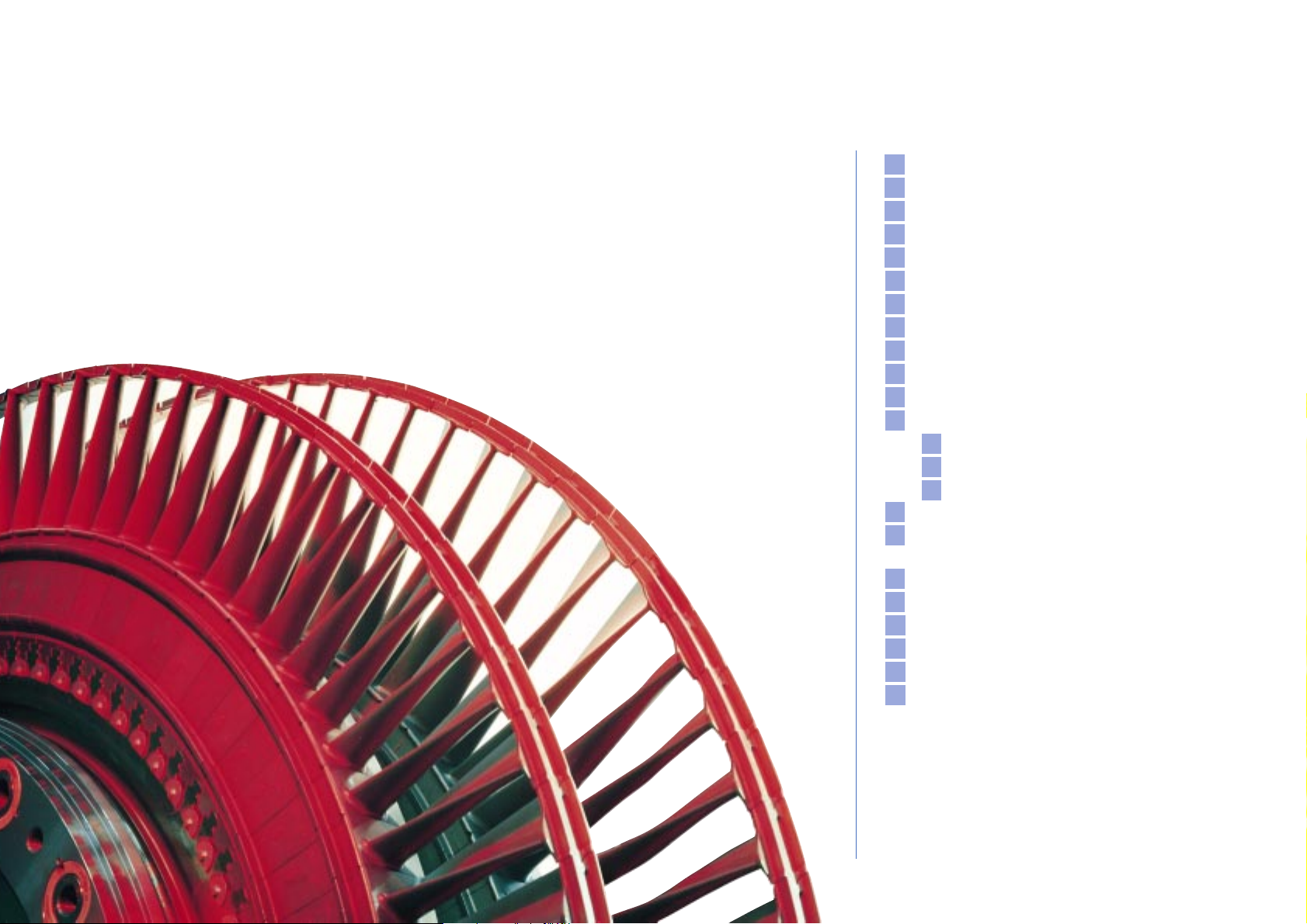
Main Components
Axial Compressor
First Stage Nozzles
Buckets and Wheels
Gas Turbine Operability
LNG Exploration and Production,
Floating Production Units
Pipeline
Refinery and Petrochemicals
Test Facilities
Service
Training
Gas Turbine Data Sheet
3
4
8
10
11
12
13
14
15
16
17
18
18
19
19
20
22
23
24
25
26
27
28
Page 3
3 GE Energy
Gas Turbines
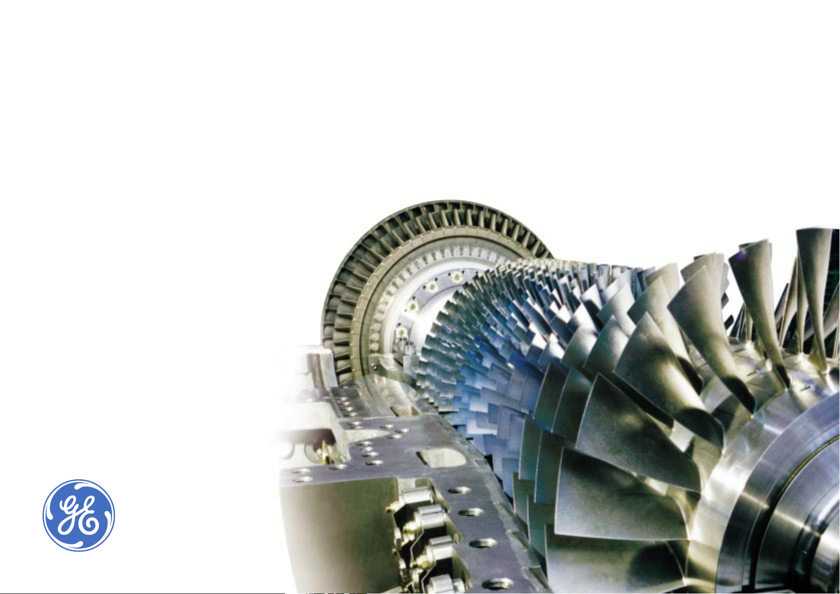
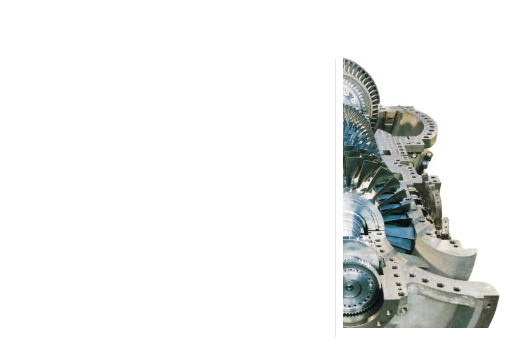
GE Energy manufactures a complete line of gas turbines for all major Oil & Gas
Industry applications. They are installed in natural gas plants, gas compression
stations, oil booster stations, petrochemical plants and power generation and
cogeneration plants worldwide. GE Energy Oil & Gas Business has long-standing
experience in manufacturing gas turbines dating back to 1961 when a
manufacturing agreement was established with General Electric (U.S.A.) to
complement the existing portfolio of products for the petroleum and petrochemical
industries (reciprocating and centrifugal compressors, gas engines, pumps, valves,
etc.). A proven combination of sound design and quality assurance techniques
places these gas turbines among the world’s most reliable. Basic models produced
by GE Energy cover the 5,000 to 124,000 kW power range. They can be provided in
simple or regenerative cycles for mechanical drive or generator drive applications.
Extensive research and development, advanced design procedures, modern
manufacturing technology and on-site experience are behind the success
achieved by GE Energy gas turbines.
Page 4
4 GE Energy
Gas Turbines
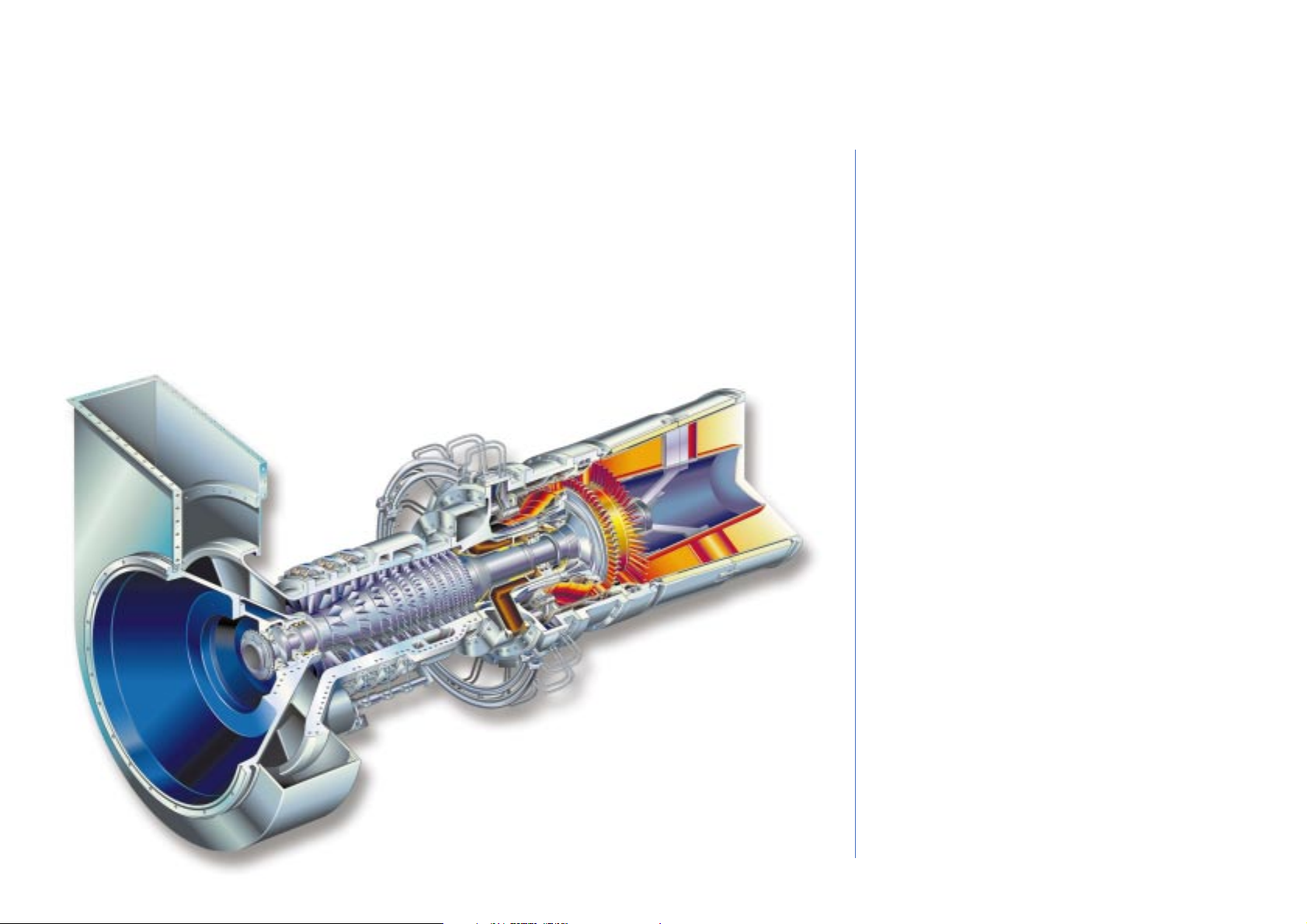
GE5 Gas Turbines
COMPRESSOR
The GE5 compressor benefits from several decades of
compressor design evolution focused on achieving
higher efficiency. The new compressor is scaled from
the similar GE10 unit. It is a high performance, axial flow
design derived from GE Aircraft Engine technology. GE
Energy, utilizing GE Aircraft Engine expertise, has greatly
improved overall compressor performance without
sacrificing reliability or mechanical integrity.
The 11-stage compressor produces a pressure ratio of
14 8:1. The first three stages of stator blades are
adjustable to optimize efficiency by maximizing exhaust
gas temperature at part load operation. Compressor
blades are assembled onto a solid forged rotor while
stator blades are mounted onto ductile cast iron
casings.
TURBINE
The HP turbine itself is a compact, high efficiency
design with two stages in the single shaft version and
three stages in the twin shaft model (2 in the LPT
Turbine). The advanced design methodology utilized by
GE Energy resulted in a high performance machine
with significantly fewer parts. In addition, state-of-theart cooling techniques permitted the use of well proven
materials.
The GE5 uses an enhanced nozzle and bucket design
similar to those used in aircraft engines. Cooling air is
provided to the first stage nozzles and buckets to
enable higher firing temperatures and enhanced
efficiency.
The LP turbine of the twin shaft version has two stages
The new GE5 is a compact, state-of-the-art, 6 MW class industrial gas turbine. The unit was
developed in two configurations: a cold-end drive single shaft for power generation and a hotend drive twin shaft for mechanical drive applications. Maximum commonality has been
maintained between the single and twin shaft models. Both units share a common gas
generator, with operating and maintenance benefits in installations where mixed operation is
required. The twin shaft engine is obtained by simply removing the second stage turbine from
the single shaft unit and adding a two-stage power turbine.
The unit is an evolution of the existing PGT5 which builds on the experience of the successful GE10
model. The merging of proven GE Aircraft Engines and GE Energy - Oil & Gas technology coupled
with the benefits of GE’s Six Sigma Total Quality Methodology have resulted in a rugged machine
with high efficiency and reliability, and low operating and maintenance cost.
The high efficiency of the machine coupled with low emissions make the GE5 a leader in its class
for most applications.
While the single shaft version is particularly suitable for power generation and cogeneration due
to the high exhaust temperature, the twin shaft version, with wide operating speed range, is
designed to be a reliable and efficient mechanical drive for compressors and pumps.
Page 5
5 GE Energy
Gas Turbines
GE5-1 Gas Turbine
and has been designed exploiting the experience the
company has gained over the past 20 years with the
PGT25, PGT10, PGT16 and more recently with the
PGT25+ (High Speed Power Turbine). The design speed of
the GE5-2 low pressure turbine is 12,500 rpm, with a
capability range from 50% to 105%, which is ideal for
direct coupling of GE Energy centrifugal compressors in
the 6 MW power range.
COMBUSTOR
The GE5 uses an annular combustor architecture, to
achieve the maximum efficiency while maintaining the
highest reliability standards. The unit is configured with
a DLE combustion system that reduces the NOx and CO
emission levels. It consists of a compact annular
combustor in Hastelloy X with 18 fuel nozzles. Each fuel
nozzle includes a double counter-rotating swirler to
optimize fuel mixing and flame stability for extra clean
combustion.
This combustion system is designed for operation on
natural gas. One fixed, high-energy spark ignitor is used
to achieve simple and reliable ignition.
Page 6
6 GE Energy
Gas Turbines
GE5 Gas Turbines
PACKAGE
The gas turbine packages were designed with an
emphasis on standardization, and optimization of
factory and field assembly operations. The result is a
standard package capable of satisfying the needs of a
typical user for low installation and maintenance costs.
The package is also designed and manufactured as a
modular system. Both the single and twin shaft gas
turbines are normally supplied as completely enclosed,
on-base soundproof packages of very compact
dimensions with standard noise attenuation levels of 85
dB(A) at 1 m. The Starting System, Lube Oil System and
Fuel System are fully integrated on the base plate.
In the single shaft configuration, the base plate also
supports the load gear; the off-base equipment is
limited to the lube oil cooler and the generator. The
entire GE5-1 package is compact, with a footprint of
only 5810 mm (L) x 2500 mm (W) providing the user with
the flexibility to locate the system indoors or near preexisting facilities. The inlet filtration module and inlet
duct are designed to be perfectly integrated with the
enclosure and, in order to optimize the footprint and
transportation, are supported by the enclosure itself.
For the twin shaft, the design guideline has been the
flexibility to satisfy a broad spectrum of customer plant
needs. As required by the Oil & Gas Industry, the
standard enclosure was designed to be equipped with
different filtration systems (conventional/self cleaning),
different inlet/exhaust duct arrangements and noise
levels and always allowing high accessibility and
maintainability.
Both the single and twin shaft packages are provided
with wide access doors conveniently located around the
enclosure for easy access to the engine assembly and
auxiliary components.
Page 7
7 GE Energy
Gas Turbines
MAINTENANCE PHILOSOPHY
A fundamental philosophy of the new GE5 gas turbine
is simplicity of design, layout and procedures. This
affords the GE5 a position of market leadership in cost
and availability through innovative programs for
service and sparing, and through package assembly
and disassembly flexibility. Drawing on GE’s undisputed
leadership in the design and manufacture of both
aero-derivative and heavy-duty machines, the GE5
represents a unique marriage of the best of both types
of engines.
This provides customers with the benefit of a variety of
cost-effective service programs (e.g., condition-based
maintenance, site-based or exchange engine programs)
and the ability to tailor the service offering to best suite
the customer’s specific applications.
SOME KEY POINTS:
Annual borescope inspections are the basis of the
condition based maintenance program.
The inspection of the hot parts is carried out
approximately every two years. Major overhaul of the
gas turbine is required at around 50,000 fired hours,
and can be completed on site, or in a shop; effects of
downtime can be minimized through the use of an
exchange engine.
GE5-2 Gas Turbine
Page 8
8 GE Energy
Gas Turbines
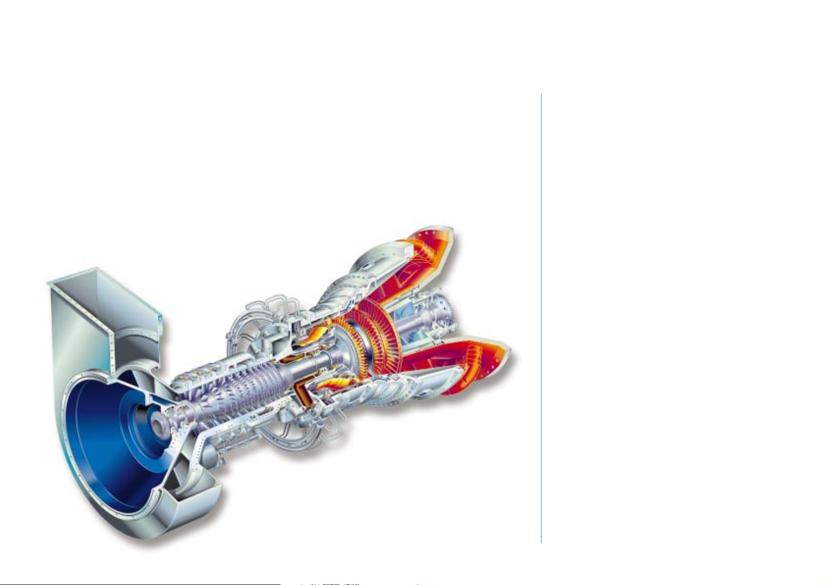
The GE10 is a 12 MW range heavy-duty gas turbine available in both single shaft and two shaft
versions. It is the evolution of the field-proven PGT10A and incorporates the latest in
aerodynamic design in a compact and versatile package arrangement. The design of the GE10
has been highly refined based on the extensive experience gained operating in all types of
environments. There are over one hundred units running under conditions ranging from the cold
of Alaska and Siberia to the heat of the desert and the humidity of the tropics.
Its efficiency and operational flexibility make the GE10 a cost-effective choice for all applications.
The gas generator consists of an 11 stage, high efficiency, axial-flow compressor and a single
combustion chamber capable of burning a great variety of fuels. Maximum commonality has been
maintained between the single and twin shaft models. Both units use the same gas generator. The
two shaft engine is obtained by simply removing the third stage turbine from the single shaft unit
and adding a two-stage low pressure power turbine. This feature is particularly beneficial in
reducing operating and maintenance costs in installations where mixed operation is required.
GE10 Gas Turbines
GE10-1 Gas Turbine
COMPRESSOR
The compressor is a high performance eleven stage
axial flow design with a 15.5:1 pressure ratio
operating under transonic flow conditions, derived
from GE Aircraft Engine aero-derivative technology.
The first three rows of stator blades are variable to
optimize cycle efficiency over a wide range of loads.
The gas generator is joined to the base plate at the
load flange location. This configuration avoids load
flange movement during all operating conditions
(start-up, warm-up, full speed/full load) and during
thermal transients.
TURBINE
The power turbine is available in two configurations: a
single shaft version primarily for power generation; and
a two shaft version for mechanical drive applications.
Generator Drive — Single Shaft Version.
The GE10-1 is a single shaft heavy duty gas turbine
designed primarili for generator drive applications.
The turbine section is composed of three reaction
stages. The first two stages use the proven design of
the previous PGT10 HP turbine model with cooling
provided by air bled from the axial compressor.
The second and third stages have interlocked shrouds to
limit tip leakage and blade vibration. At partial load, inlet
variable guide vanes permit optimization of performance
with no appreciable change from simple cycle full load
efficiency.
The GE10 is a compact turbogenerator optimized for
simple cycle, combined cycle and cogeneration plants
(e.g., power shaft on cold side; axial discharge of hot
gases) and suitable for utilization even where space is
limited.
Page 9
9 GE Energy
Gas Turbines
Mechanical Drive — Two Shaft Version.
The GE10-2 is the two shaft version of the GE10
intended for mechanical drive applications. The turbine
consists of four reaction stages. The first two stages or
High Pressure Turbine which are used to drive the axial
compressor are common with the GE10-1 model. The low
pressure shaft is a double stage, high-energy turbine with
variable first stage nozzles which provide maximum
flexibility for mechanical drive applications. These third and
forth stages which make up the Low Pressure Turbine are
coupled to the power shaft driving the load. They are
cooled by air bled from the axial compressor.
COMBUSTOR
The combustion system consists of a single, slot-cooled
combustion chamber assembly that permits quick and
easy maintenance of the hot gas path. This combustion
chamber is able to burn a wide range of fuels including
liquid distillates, residuals and all gaseous fuels including
low BTU gas with system modifications.
The GE10 combustion system is available in both
conventional and DLE configurations. The DLE (dry low
emissions) system is a simple, field-proven design that
guarantees operation at 25 ppmv NOx (burning Natural
Gas). The GE10 can also utilize steam and water
injection for NOx reduction and power augmentation.
Further reduction of emission levels is a constant
objective of our continuing combustion development
and test programs.
AUXILIARIES
The integrated lubrication system (including oil tank)
that feeds the gas turbine, the speed reduction gear and
the electric generator is located on the turbine base
plate. The main lube oil pump is mechanically driven by
the gearbox. An AC electric motor-driven pump
guarantees lubrication during normal operation while a
DC electric motor-driven pump is provided for
emergency backup. In the standardized package
configuration the oil is cooled by an air cooler. A water
cooler can be provided upon customer request.
The thrust and journal bearings are of the tilting pad type.
The starting system consists of a V.F.D. motor drive for the
single shaft version.
The twin shaft can be equipped with a torque converter
plus electric motor or starting expansion turbine.
The GE10 control system has been implemented to
assure a high degree of integration and standardization
between the engine and the turbine generator package.
Programmable modules guarantee easy
implementation of any control and protection scheme
to tailor the control system to the application and
customer needs.
PACKAGE
The package designed for power generation
applications is optimized to minimize plant dimensions
and to reduce maintenance cost and time. In the
standard configuration, the speed reduction gear is
mounted on the gas turbine base plate. The auxiliaries
are installed on a separate base plate permanently
joined to that of the gas turbine base plate to form a
single lift on which the sound-insulated enclosure is
mounted.
The electric generator is installed on a concrete
foundation to limit the shipping dimensions. The overall
length of the genset is about 13 m.
The other modules completing the system are the
oil/air exchangers, the air intake filter chamber, the
suction duct (vertical suction) and the exhaust system
(axial exhaust).
The enclosure has a sound pressure level lower than 85
dBA at 1 m. This acoustic design meets ISO NR 50 limits
at 100 m.
Page 10
10 GE Energy
Gas Turbines
MS5001 Gas Turbines
MS5001 Gas Turbine
The MS5001 single shaft turbine is a compact heavy-duty prime mover designed for long life and ease
of operation and maintenance. The three main features of its simple design are:
- 17-stage, axial compressor
- Combustion system with 10 chambers capable of burning a wide range of fuels including natural
gas, light and heavy distillates, and crude and residual oil. A DLN System is also available.
- Two-stage turbine with high energy stage design. The first-stage nozzles are cooled by the axial
compressor discharge air.
The MS5001 Gas Turbine is the ideal solution for power generation where low maintenance, reliability
and economy of fuel utilization are required. Low operating and investment costs make the MS5001
package power plant an economically attractive system for load generation. The MS5001 is also
ideally suited for cogeneration achieving a very high fuel utilization index and considerable fuel
savings. Typical applications are industrial plants for cogeneration of power and process steam or
district heating systems.
As a consequence of the extremely favorable operating, maintenance and economic
characteristics of the MS5001 it has been very well accepted in the industry and there are more
than 2500 units in operation all over the world.
Page 11

The MS5002 is a gas turbine specifically designed for mechanical drive applications such as gas
boosting, gas injection/re-injection, oil & gas pipelines, LNG plants and gas storage. It has a broad
operating speed range to meet the operating requirements of the most common driven equipment
(centrifugal compressors and pumps) as well as the ability to burn a large variety of gaseous and
liquid fuels. The MS5002 gas turbine was introduced in the market in the 1970s and has been
updated and up-rated over the years to meet the industry demand for increased output. Presently
two versions are available:
- MS5002C
- MS5002D
The MS5002 two-shaft, heavy-duty gas turbine is designed for high operating efficiency over a wide
range of speed and load. The simple design and extreme robustness of the MS5002 allow complete
maintenance to be performed on site without the need for specialized tooling or service shop
assistance. The main features of its design are:
- High pressure shaft consisting of a 16-stage (17 for MS5002D), axial-flow compressor and a
single-stage, high energy turbine. The first stage nozzles are air cooled and the second stage
nozzles are of the variable angle type.
- Low pressure shaft is a single stage, high energy turbine.
- Twelve combustion chambers are contained within a single wrapper. A wide range of gaseous
and liquid fuels can be burned. A DLN Combustion System is also available.
- A centralized lube oil system supplies clean, cooled, pressurized oil to lubricate the gas turbine
and the driven equipment including the oil required for any compressor seals.
As a consequence of the extremely favorable operating, maintenance and economic characteristics
of the MS5002 nearly 500 units (more than 300 manufactured by GE Energy) have been installed
world-wide in all types of environments (arctic, desert, off-shore etc.) always demonstrating ease of
operation and very high reliability and availability.
11 GE Energy
Gas Turbines
MS5002C-D Gas Turbines
MS5002 Gas Turbine
Page 12

EXPECTED PERFORMANCE
Output Shaft 32 MW
SC Efficiency 36%
Pressure Ratio 17:1
LPT Shaft Speed 5714 rpm
Exhaust Temperature 511 °C
NOx Emission 25 ppm
12 GE Energy
Gas Turbines
The MS5002E, the latest addition to the GE Energy family of gas turbines, is a 32MW class
machine designed for high efficiency, low environmental impact and high reliability. The MS5002E
will be available in both single and dual-shaft versions to cover power generation and mechanical
drive applications.
This latest model was developed in response to customer demand for a machine in the 32 MW range
with low fuel consumption, reduced emissions and high availability and reliability. In order to
guarantee high reliability and availability the MS5002E has a conservative firing temperature with
respect to the state-of-the-art. High efficiency was achieved through the use of advanced design
tools to optimize airfoils, clearances, leakages and the distribution of cooling flows.
The MS5002E offers NOx emission levels down to 25 ppm through the use of a dry-low emission
combustion system derived from the GE Energy DLN2 combustion technology.
The design of the MS5002E was thoroughly validated through an extensive test program that
included a full scale test of the axial compressor, full scale rotordynamic testing and full load
testing of the gas turbine system.
The MS5002E single and dual shaft 32MW class machine represents a world-class engineering
achievement to provide customers with a high efficiency, low emissions machine with outstanding
reliability matched for Oil & Gas Industry applications.
MS5002E Gas Turbines
MS5002E Gas Turbine
Page 13

MS6001B
The MS6001 is a single-shaft, heavy-duty gas turbine. The
high efficiency axial compressor has 17 stages. The
combustor has ten combustion chambers with individual
fuel nozzles. The machine has a three-stage impulse turbine
with air-cooled buckets and stationary nozzles on the first
two stages to achieve higher firing temperatures and
consequently higher efficiency without compromising hot
section component life.
MS7001EA
The GE MS7001EA is a highly reliable, mid-sized
packaged power plant developed specifically for 60 Hz
applications. With design emphasis placed on energy
efficiency, availability, performance and maintainability,
the 7EA is a proven technology machine with more than
775 units of its class installed or on order worldwide as
of December 1999. The simple, medium-sized design of
the 7EA lends itself to flexibility in plant layout and
easy, low cost addition of power augmentation when
phased capacity expansion is needed. A predecessor of
the 7FA, the 7EA is ideal for plants that require high
efficiency along with shaft speed for direct coupling to
the generator.
13 GE Energy
Gas Turbines
MS6001B/MS7001EA/MS9001E
Available for Oil & Gas Applications
MS6001B
Gas Turbine
MS7001EA
Gas Turbine
MS9001E
Gas Turbine
FEATURES
- 17-stage compressor with stacked disk design
- reverse flow combustion system with an individual nozzle single
combustion chamber
- 3-stage turbine with air-cooled, first and second-stage nozzles and
buckets
- three-bearing rotor supports
MS9001E
The MS9001 is a single-shaft, heavy-duty gas turbine
developed for generator drive service in the 50 Hz
market. Its efficiency is approx 33% in simple cycle
mode and over 50% when operated as a combined
cycle. The MS9001 is designed to burn a variety of
liquid and gaseous fuels.
APPLICATIONS
The 7EA is fuel-flexible, and can operate on natural gas,
liquefied natural gas (LNG), distillate and treated residual
oil in a variety of applications including:
- mechanical drive for large compressor trains
- simple cycle and combined cycle
- base load and peaking power generation
- industrial and cogeneration
Page 14

14 GE Energy
Gas Turbines
The PGT16 gas turbine consists of the twin spool GE Aeroderivative LM1600 Gas Generator coupled
with a rugged, industrial power turbine designed by GE Energy’s Oil & Gas businesses. The LM1600
Gas Generator is derived from the F404 turbofan aircraft engine.
The power turbine of the PGT16 gas turbine is identical to that of the PGT10 heavy duty, high
efficiency gas turbine which has been in operation for more than half a million hours.
The power turbine shaft speed (7900 RPM) is optimized for direct coupling to pipeline, injection and
process centrifugal compressors with a speed range that matches most operating requirements
encountered in oil & gas applications. For generator drive applications the PGT16 synchronously
coupled to a generator with a speed reduction gear is a highly flexible turbogenerator which can be
operated as a simple cycle or in combined or cogeneration cycle applications with an electrical
efficiency close to 50%.
GENERAL SPECIFICATIONS
Compressor
- Twin spool axial compressor (3 stage LP compressor,
7 stage HP compressor)
- Pressure ratio 20.1:1
Combustion
- Annular combustion chamber (18 fuel nozzles)
Turbine
- Twin Spool Gas Generator turbine (1 stage HP
turbine, 1 stage LP turbine)
- Two stage Power turbine with variable angle first
stage nozzles
Package
- Completely mounted on a single base plate
- The enclosure is integral with the base plate
providing maximum accessibility for maintenance
of the gas turbine and auxiliaries
Emission Control
- Steam or water injection systems for NOx abatement
- Dry Low Emission (DLE) combustion system
PGT16 Aeroderivative Gas Turbines
PGT16 Gas Turbine
Page 15

The PGT25 gas turbine consists of an LM2500 GE aeroderivative gas generator coupled with a
rugged, industrial power turbine designed by GE Energy.
GAS GENERATOR
The LM2500 GG has already accumulated several million fired hours not only as an aircraft
engine (TF39 and CF6-6 engines), but also in the industrial field in many mechanical drive
applications (marine, onshore and offshore gas transmission) and for generator drive service.
The LM2500 gas generator incorporates a 16-stage axial-flow compressor capable of reaching
an 18:1 pressure ratio. Inlet guide vanes and adjustable stator vanes on the first six compressor
stages provide for efficient operation over the entire operating range.
POWER TURBINE
The PGT25 power turbine components were designed by GE Energy taking into account many
years of experience gained in the field of heavy duty gas turbines and axial/centrifugal
compressors. The aerodynamic blading was designed with the main objective of obtaining very
high efficiency at both design and reduced speeds.
The 6500 RPM design speed means the turbine can have two stages with a moderate
aerodynamic load and a high expansion efficiency. The two expansion stages are of the high
energy, three-dimensional design type.
The investment casting superalloy selected for the blading assembly has a cobalt base for the
nozzles and a nickel base for the rotor blading (i.e. the same materials used on heavy-duty gas
turbines). A large creep and fatigue (LCF-HCF) safety margin on blade life is ensured by a
moderate gas temperature at the power turbine inlet. The two-stage rotor is overhung and the
shaft is supported by two tilting pad bearings contained in a cylindrical cartridge. The system
can be easily dismantled with a simple translation of the gas generator within the package
space thus reducing the time required for a major overhaul of the power turbine to a few days.
Engineering simplicity and advanced materials yield long time between overhauls and reduced
maintenance costs.
The turbine is assembled on a light but rigid base plate with extensive use of prefabricated
standard components preassembled and tested in the shop to minimize on-site assembly time.
GENERAL SPECIFICATIONS
Compressor
- Sixteen stage axial compressor
- Pressure ratio 17.7:1
Combustion
- Annular combustion chamber (30 fuel nozzles)
Turbine
- Two stage Gas Generator turbine
- Two stage Power turbine (6500 RPM).
Package
- Completely mounted on a single base plate
- The enclosure is integral with the base plate
providing maximum accessibility for maintenance
of the gas turbine and auxiliaries
Emission Control
- Steam or water injection systems for NOx abatement
- Dry Low Emission (DLE) combustion system
15 GE Energy
Gas Turbines
PGT25 Aeroderivative Gas Turbines
PGT25 Gas Turbine
Page 16

16 GE Energy
Gas Turbines
The PGT25+ gas turbine was developed for 30 MW ISO shaft power service with the highest
thermal efficiency level (approx. 40%). The PGT25+ gas turbine consists of the GE Aeroderivative
LM2500+ Gas Generator (updated version of the LM2500 gas generator with the addition of a
zero stage to the axial compressor) coupled with a 6100 RPM, 2 stage Power Turbine (High Speed
Power Turbine - HSPT). Built on the LM2500 heritage and demonstrated 99.6% reliability, the
LM2500+ incorporates technology improvements and a large percentage of parts in common
with the LM2500 to deliver the same outstanding level of reliability. Designed for ease of
maintenance, the LM2500+ also provides a high level of availability. High efficiency and reliability
are among the large number of benefits contributing to PGT25+ customer value.
Specialized aeroderivative annular combustion chamber fuel nozzles makes the PGT25+ ideal for
a wide range of mechanical drive (gas pipeline etc.), power generation, industrial cogeneration,
and offshore platform uses in any environment.
Engineering simplicity and advanced materials yields long time between overhauls and reduce
maintenance costs.
GENERAL SPECIFICATIONS
Compressor
- Seventeen stage axial compressor
- Pressure ratio 21 15:1
Combustion
- Annular combustion chamber (30 fuel nozzles)
Turbine
- Two stage Gas Generator turbine
- Two stage Power turbine (6100 RPM).
Package
- Gas Generator, Power Turbine and auxiliary systems
mounted on a single base plate
- The enclosure is integral with the base plate providing
maximum accessibility for maintenance of the gas
turbine and auxiliaries
Emission Control
- Steam or water injection systems for NOx abatement
- Dry Low Emission (DLE) combustion system
PGT25+ Aeroderivative Gas Turbines
PGT25+ Gas Turbine
Page 17

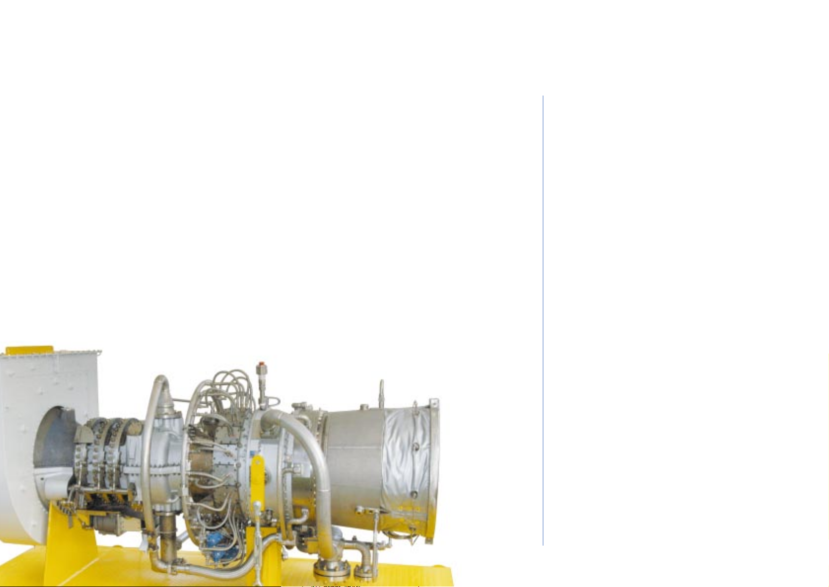
The LM6000 is a simple-cycle, two-shaft, high performance gas turbine derived from the
GE CF6-80C2 high bypass turbofan aircraft engine, the industry standard for high-thrust engines.
Delivering more than 44.8 MW at over 42.7% thermal efficiency, the powerful LM6000 is the most
fuel-efficient, simple-cycle gas turbine in the world. Direct drive provides 60,000 shaft
horsepower from either end of the low pressure rotor for a wide range of electric power
generation and mechanical drive applications in any environment.
High thermal efficiency, low cost, and installation flexibility make the LM6000 the ideal choice as
a prime driver for utility peaking, mid-range, and base load operations, as well as for industrial
cogeneration.
The LM6000’s design allows full speed range capability from 50-105% of the rated speed of 3600 RPM.
Continuing the tradition of the established record of GE’s LM2500, the LM6000 is ideal as a source
of drive-power for pipeline compression, offshore platform and gas re-injection, as well as for
LNG compressors. The LM6000 was GE’s first aeroderivative gas turbine to employ the new Dry
Low Emissions (DLE) premixed combustion system. DLE dual fuel, water or steam injection can
also be used to achieve low NOx emissions.
17 GE Energy
Gas Turbines
LM6000 Aeroderivative Gas Turbines
GENERAL SPECIFICATIONS
Compressor
- Two axial compressor (LPC, HPC)
- LPC five stage
- HPC fourteen stage
- Pressure ratio 28,5:1
Combustion
- Annular combustion chamber (30 fuel nozzles)
Turbine
- Two stage HPT
- Six stage LPT (3600 RPM)
Package
- Gas Generator, Power Turbine and auxiliary systems
mounted on a single base plate
- The enclosure is integral with the base plate providing
maximum accessibility for maintenance of the gas
turbine and auxiliaries
Emission Control
- Steam or water injection systems for NOx abatement
- Dry Low Emission (DLE) combustion system
LM6000 Gas Turbine
Page 18

18 GE Energy
Gas Turbines
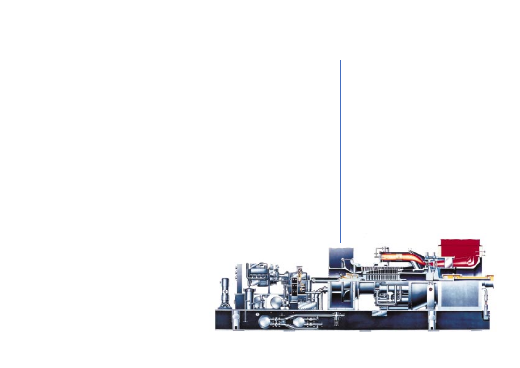
Axial Compressor
The compressor rotor is made of separately forged wheels (all models except the GE5 and part of
the GE10 which have a solid forged rotor). Each individual wheel undergoes inspection and is Xrayed for material flaws. In addition, each wheel is balanced individually and the rotor is
balanced on three planes. Rabbet fits are used to ensure concentricity and multiple through-bolts
secure the wheels to form a correctly pre-stressed assembly. The blades are held in the
compressor rotor and stator rings by dovetail platforms. The stainless steel blades provide
excellent corrosion resistance and good internal damping characteristics. The large chord, broadblade compressor blades have low stresses and the unique ability to withstand damage by small
foreign objects as well as to maintain high performance in spite of normal wear and
contamination. The stator casing is horizontally split for ease of assembly, maintenance and
inspection. Iron castings give dimensional and thermal stability to maintain good radial tip
clearances for maximum power and efficiency. Several compressor designs are available
covering pressure ratios in the 8-17 range and air flows from 20 to 400 Kg/sec with 11-17 stage
configurations. The GE5, GE10 and MS5002E compressors have variable geometry, implemented
by means of adjustable vanes (inlet guide vanes and first stages stator vanes), in order to
provide flow control within the operating range.
Main Components
Page 19

19 GE Energy
Gas Turbines
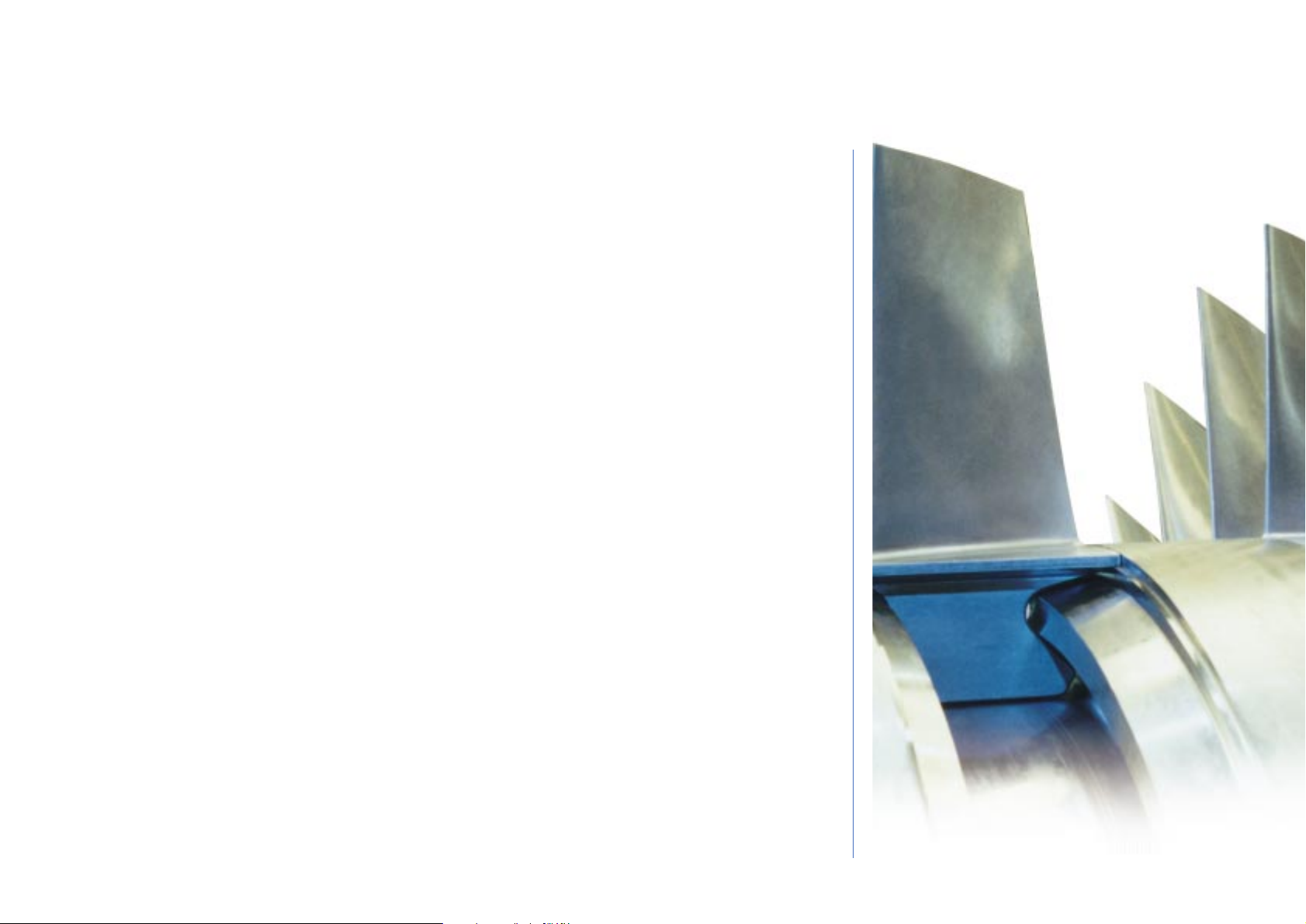
First Stage Nozzle
The complete first stage nozzle assembly consists of airfoil-shaped vanes which are contained
between an inner and an outer sidewall. The design of the nozzle assembly and the arrangement
for its support within the turbine shell accommodate the effects of thermal expansion caused by
the hot gases and keep the assembly properly aligned in the gas path. Seals in the turbine
shell prevent leakage of combustion gases around the nozzle from the inlet to the
exhaust. Compressor discharge air is fed to these sealing rings through orifices in
the shell. A key feature of the first-stage nozzle is the air-cooled partition which
increases nozzle life substantially. Cooled air from the compressor discharge is
directed through the body of the individual nozzle partitions and out holes near
the trailing edge. This not only cools the metal, but blankets the trailing edge
with a film of air. Additionally, relatively thick nozzle partition trailing edges
provide increased strength and oxidation resistance, again providing longer
nozzle life.
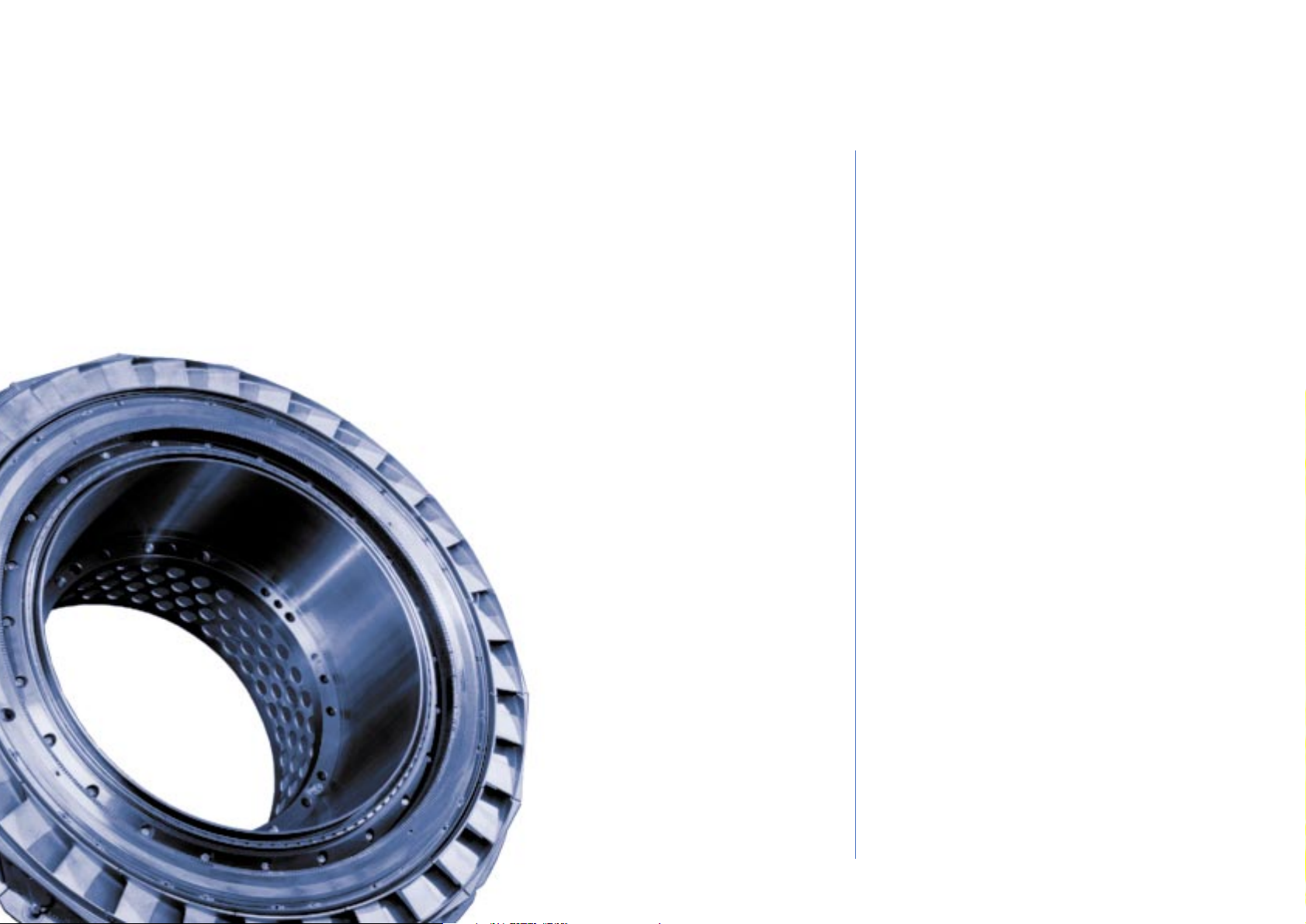
Buckets and Wheels
The long shank bucket design lowers the turbine wheel rim a substantial distance below the hot
gas path. The high thermal resistance of the shank results in a considerable temperature drop
between the hot bucket vane and the wheel dovetail, thus reducing temperature levels and
gradients in the turbine wheel and the dovetail area where rotating stresses are high. Further
wheel protection is provided by radial seals on the first-stage bucket shanks that restrict hot gas
leaks into the wheel cavities. Compressor bleed air is used to cool the wheels and maintain
relatively low temperature levels.
Page 20

20 GE Energy
Gas Turbines
Large Operability Window
GE Energy offers a variety of innovative design solutions to maximize the operability window of
the Oil & Gas gas turbine fleet. In addition to variable stator vanes and blow-off valves, the design
solutions include:
- variable turbine nozzle guide vanes
- a variable bypass combustion chamber
- a high turn-down capability combustion chamber
- CPC optimizing control logic
The various combinations of design solutions are specifically adapted to the demands of the
marketplace for each gas turbine model.
For example: The GE10-2 DLN (Dry Low NOx) model utilizes a variable bypass
combustion chamber to maintain the optimum flame temperature for low emissions
all the way down to 50% load, and the variable nozzle guide vanes of the free power
turbine to ensure that the gas generator shaft speed is always at the design value,
thereby ensuring maximum output.
The MS5002D instead uses variable nozzle guide vanes to maintain maximum
output on the standard model, and maintain the optimum flame temperature for
low emissions down to 50% load on the DLN model. They are also used in
regenerative cycle applications to maximize the efficiency of the regenerator and
hence to maximize fuel economy.
The brand new MS5002E makes use of the DLN2 combustion design used in GE’s
F-Class machines to ensure low emissions over a range of flame temperatures,
thereby delaying the opening of the blow-off valves at part load while maintaining
the highest possible efficiency at base-load.
Note that the flexibility given by each of these solutions gives a further
performance advantage on cold days with respect to other engines that are forced
to open blow-off valves (to meet environmental emissions laws) even at base-load.
Gas Turbine Operability
MS5002D Gas Turbine
Page 21

21 GE Energy
Gas Turbines
CPC Logic
One of the enhancements recently introduced by GE Energy is the Corrected Parameter Control
logic (CPC). This type of control philosophy applies principally to mechanical drive units, and
consists of an exhaust temperature control curve that self adjusts according to the condition of
the inlet filters and actual power turbine speed. This allows the engine to be operated at
optimum conditions not only at the nominal point, but over the entire operating envelop of inlet
conditions and power turbine speeds. The results of this improvement have already been proven
in the field, as shown in the following figure (relating to the test of a GE10-2 unit at various free
power turbine speeds). Thanks to the application of CPC logic it has been possible to significantly
increase the maximum output without compromising the safe operation of the unit by simply
optimizing its operation in real-time.
The variable free power turbine speed element of the CPC logic is provided as standard on the
GE5-2, MS5002D DLN and MS5002E models, and on all new GE10-2 units. The possibility to
retrofit existing gas turbine models with this solution is also offered.
Ambient Temperature 22°C
102
101
100
99
98
97
96
95
94
93
92
91
Shaft Power (%)
90
CPC Control Logic
75 80 85 90 95 100 105
Power Turbine Speed (%)
Old Control Logic
Page 22

22 GE Energy
Gas Turbines
Gas, Water Injection & Gas Storage Units
Gas compression is a critical operation in the Oil & Gas production chain. Therefore reliability is a
key factor in the design of GE Energy natural gas compressors.
GE Energy has delivered over 200 compressor trains for gas reinjection and gas storage
applications. Of the more than 380 casings supplied, 105 have a design pressure higher than
7,200 psia (500 bar a). Our many years of experience in designing, manufacturing, installing and
servicing these machines has validated GE Energy designs and production processes. Reliability
of this rotating equipment is directly related to rotor stability and impeller integrity throughout
the entire envelope of operating conditions and GE Energy machinery has been successfully
proven by long years of service under the challenging conditions found in the Oil & Gas Industry.
The high level of power involved in these compression applications requires gas turbines as
drivers. GE Energy provides a complete range of mechanical drive gas turbines that are ideally
matched to Oil & Gas applications. The extensive use of the GE MS6001 and MS7001EA single
shaft gas turbine technology for LNG mechanical drive applications is a result of our plant
integration services and the ability to optimize the design of both the gas turbine and the
compressor for these applications. The result is flawless performance of turbocompressors that
have accumulated more than 100,000 hours of operation in the largest LNG plants in the world.
The ability of GE Energy to integrate, test and deliver the entire turbocompressor train is a great
advantage to the Customer in terms of optimization of the system performance, delivery time
and the efficiency of working with a single supplier.
LNG Exploration and Production, Floating Production Units
Ras Laffan
Mesaieed - Qatar
MS5002 Turbo units for
LNG and Ammonia
Synthesis
Woodside - Australia
MS5002C LNG main refrigerant
compressor drive
Bongkot Field - Thailand
Single lift module for
offshore application
PGT25 Gas Turbines
Hassi R’ Mel - Algeria
Natural Gas Re-injection plant
36 MS5002 Gas Turbines
Page 23

23 GE Energy
Gas Turbines
Pipeline Standard Units/Packages
The gas turbines manufactured by GE Energy have features that make them particularly
suitable for pipeline compressor applications; GE Energy’s pipeline centrifugal compressor line
complements its gas turbine line to optimize matching with the gas turbine driver resulting in
perfectly integrated gas turbine compressor units.
Specific pipeline service requirements, flexibility in meeting varying operating conditions,
reliability, availability and unattended remote control are fully satisfied by these gas turbine
and pipeline compressor lines. Direct compressor turbine couplings improve the reliability and
efficiency of gas turbine-compressor units reducing the spares inventory. Compact integrated
turbine-compressor units make for easy transportation and rapid on-site commissioning. All
units are on structural steel base plates, completely shop piped, wired, instrumented tested and
ready to be shipped to the site minimizing commissioning time.
Pipeline
Blue Stream
Pipeline Project from
Turkey to Russia
PGT25 - BCL406/b
Sbikha - Tunisia
PGT 25 - PCL603
Pipeline Compressors
Biskra - Algeria
OK1 - SP3bis Station
GE10-2
Cape Bon - Tunisia
Trans-Med Pipeline Cape Bon to Sicily
Head Station 25 MW Gas Turbine
Driven Booster Compressors.
MS5002 - BCL404/a
Feriana - Tunisia
PGT25 - PCL600
Page 24

24 GE Energy
Gas Turbines
Downstream Plants
Gas turbine-driven centrifugal compressors are also used in Downstream process industries such
as refineries and petrochemical and fertilizer plants that need flexible and reliable compression
trains.
GE Energy turbocompressors are individually tailored to meet the customer’s performance
requirements. They combine in a packaged unit the extensive experience gained by our
company on both types of machines and the advantages of a single source of supply--fully
integrated auxiliary systems and high operational flexibility and reliability.
Typical applications include:
- Process air centrifugal compressor drive in ammonia synthesis plants
- High power centrifugal or axial compressor drive in Gas to Liquids plants
- Production of compressed air from the turbine axial compressor section and compressor drive
in air fractionating processes.
Refinery and Petrochemicals
Livorno - Italy
MS9001 Turbogenerator units
for Refinery plant
Rhourde Nouss - Algeria
MS5001 - MS3001 Gas Turbines and
2BCL 406B Compressors
Mesaieed - Qatar
MS5001 Turbogenerator units
for Fertilizer plant
Page 25

GE Energy carries out mechanical tests on all its gas turbines. Complete turbocompressors and
turbogenerators, including all auxiliary equipment, can be full-load tested on outdoor test beds
complying with API, ASME, VDI and ISO international standards at the Florence or Massa plants.
Even complete modules can be tested at the Massa plant and than shipped without being this
assembled because of its proximity to the Massa harbor. The test beds are equipped with
computer Data Acquisition Systems capable of collecting thermodynamic and mechanical data
and computing in real time. Test facilities include a high pressure feed system for gas mixtures
(inert and flammable gases), a gas chromatograph for gas analysis, a 60 Hz generator, low and
high pressure gas coolers, and steam and lube oil supply. The cooling towers allow closed-loop
tests up to 130 MW. GE Energy also tests complete plants on site upon customer request.
25 GE Energy
Gas Turbines
Test Facilities
FLORENCE PLANT
Indoor stands for gas turbine tests
4
L
O
M
R
O
T
B
O
N
R
O
C
3
to test
beds 1-4
NATURAL GAS
DIESEL
TANK
Shop electric generator + gear box
Gas turbine test
LUBE OIL
CONSOLE
A
CONTROL
ROOM
1
5
LUBE OIL
VACUUM
CONSOLE
SYSTEM
B
Shop electric motor + gear box
Gas turbine test :
Low pressure shaft
A
LUBE OIL
CONSOLE
C
2
LUBE OIL
CONSOLE
FLORENCE PLANT
Stand Utilities
TO INDOOR STANDS FOR GAS TURBINE TESTS 1 - 4
Air cooler
COGENERATION
PLANT
LIQUID
GAS
FLORENCE PLANT
Outdoor string and load test stands
4
3
L
O
M
R
O
T
B
O
N
R
O
LUBE
C
OIL
2
1
MOBILE
VACUUM
SYSTEM
INDOOR
TEST
STANDS
Centrifugal/ axial compressor test
Gas turbine test
MASSA PLANT
Outdoor stands for gas turbine tests
and turbogroup full load tests
D
To Test Beds
Towers
Evaporating
From Test Beds
LUBE
OIL
TANK
DIESEL
TANK
LUBE OIL
CONSOLE
ELECTRIC
SYSTEM
MOBILE
VACUUM
SYSTEM
COMPRESSED
AIR
SYSTEM
LIQUID
GAS
Centrifugal / axial compressor test Hydraulic dynamometer
Gas turbine test
TANK
Shop electric generator + gear box
a
c
b
d
e
CONTROL
ROOM
TO OUTDOOR
STANDS 1 - 4
2HM
2BVTN
TO OUTDOOR
STANDS 5 - 8
2BVTN
GAS
STORAGE
OUTDOOR
STANDS
a
b
Condenser
INDOOR
TEST
STANDS
5
6
8
d
c
Back
Pressure
a,b,c,d
e
2HM
2BVTN
GAS
STORAGE
MEASURING
STA
TION
f
f
COMPRESSED
AIR
SYSTEM
ELECTRIC
SYSTEM
A
7 a7 b
To Test Beds
To Test Beds
a,d,e
CONTROL
ROOM
A
CONTROL
ROOM
B
TO INDOOR
AND OUTDOOR
STANDS
Steam generator
FROM INDOOR
AND OUTDOOR
STANDS
Steam System
Cooling Water
g
b
f f
Evaporating
Towers
MEASURING
STA
TION
NATURAL GAS
e
FROM
DOMESTIC
NETWORK
f
Page 26

26 GE Energy
Gas Turbines
Service
GE Energy provides a complete set of services to support the entire gas turbine product line. We
offer an extensive portfolio of proactive and interactive service products such as condition-based
maintenance and long term service agreements complementing the traditional service offerings
of OEM spare parts, repairs, and field services.
Our innovations are not limited to mechanical engineering. We have developed business
solutions such as remote monitoring & diagnostics to help drive customer value by providing
higher equipment reliability, availability, and productivity at a predictable cost.
Other advanced information-based developments include electronic parts catalogs, and
e-commerce solutions.
Global Services engineers are backed up by the new product design engineering groups of GE
Energy and by the GE Global Research Center --hundreds of creative minds working to provide
the high-tech products and business solutions for the 21
st
century.
Page 27

GE Energy offers Training for the Operation and Maintenance of our complete line of machinery
and equipment.
This Training can be provided either at the client’s site or at the Learning Center located at GE
Energy headquarters in Florence, Italy. Instructors are field-seasoned experts who combine their
understanding of theory with practical experience.
The quality training that they provide is a prerequisite for improving the skills of operating and
maintenance personnel skills, to assure safety, and superior equipment efficiency and availabily.
Courses and and documentation are designed to meet Customer needs, focusing on the GE
Energy machinery and equipment actually installed at their sites.
Traditional training tools are augmented with computer-based training and interactive
multimedia technology. Courses and technical literature can be provided in a variety of
languages.
27 GE Energy
Gas Turbines
Training
CENTER OF EXCELLENCE FOR TRAINING
Florence Learning Center Facilities:
- 5600 m
2
of Space
- More than 20 Training Rooms
- Speedtronic Mark V & Mark VI
- Bently Nevada Simulators
- Laboratories
- Multimedia Rooms
- Conference Center
- Auditorium Seating for 230 (under completion)
TRAINING SOLUTIONS:
-
For all level in your organization
- Tailored for your specific needs
- Pre-scheduled offerings or on request
- Provided in various languages
- Formal classroom training and interactive learning
COVERED EQUIPMENT
Nuovo Pignone, Thermodyn, Rotoflow, Bently Nevada
and other GE Energy equipment.
Page 28

Generator Drive
(ISO conditions - natural gas - electrical generator terminals)
ISO RATED HEAT RATE EFFIC. PRESSURE EXHAUST TURBINE EXHAUST
POWER RATIO FLOW SPEED TEMPERATURE
kW kJ/kWh % kg/sec Ibs/sec RPM °C °F
PGT5 5,220 13,422 26.8 9.1 24.6 54.2 10,290 523 973
GE5 5,500 11,740 30.7 14.8 19.6 43.1 16,630 574 1,065
PGT10 10,220 11,540 31.2 13.8 42.3 93.3 7,900 488 910
GE10 11,250 11,481 31.4 15.5 47.5 104.7 11,000 482 900
PGT16 13,720 10,300 35.0 20.2 47.3 104.3 7,900 491 919
PGT20 17,464 10,238 35.2 15.7 62.5 137.7 6,500 475 887
PGT25 22,417 9,919 36.3 17.9 68.9 151.9 6,500 525 976
PGT25+ 30,226 9,084 39.6 21.6 84.3 185.9 6,100 500 931
LM6000 42,703 8,770 41.0 27.9 125.8 288.8 3,600 452 840
MS5001 26,830 12,687 28.4 10.5 125.2 276.1 5,094 483 901
MS5002E 31,100 10,285 35.0 17.0 102.0 225.0 5,714 511 952
MS6001B 42,100 11,230 32.1 12.2 141.1 311.0 5,163 548 1,026
MS7001EA 85,400 10,990 32.7 12.6 292.0 643.0 3,600 537 998
MS9001E 126,100 10,650 33.8 12.6 418.0 921.0 3,000 543 1,009
28 GE Energy
Gas Turbines
Page 29

29 GE Energy
Gas Turbines
Mechanical Drive
(ISO conditions - natural gas - shaft output)
ISO RATED HEAT RATE EFFIC. PRESSURE EXHAUST TURBINE EXHAUST
POWER RATIO FLOW SPEED TEMPERATURE
kW shp kJ/kWh btu/shp-h % kg/sec Ibs/sec RPM °C °F
PGT5 5,440 7,295 13,470 9,523 26.7 8.6 25.8 56.9 10,290 533 991
GE5 5,600 7,510 11,429 8,080 31.5 14.6 20.0 44.2 12,500 556 1,032
PGT10 10,660 14,295 11,060 7,819 32.5 13.8 42.3 93.3 7,900 488 910
GE10 11,982 16,068 10,822 7,651 33.3 15.5 46.9 103.3 7,900 480 896
PGT16 14,240 19,096 9,930 7,020 36.3 20.2 47.3 104.3 7,900 491 919
PGT20 18,121 24,300 9,867 6,975 36.5 15.7 62.6 137.9 6,500 475 887
PGT25 23,261 31,193 9,560 6,759 37.7 17.9 68.9 151.9 6,500 525 976
PGT25+ 31,364 42,060 8,754 6,189 41.1 21.6 84.3 185.8 6,100 500 931
LM6000 43,679 58,575 8,600 6,080 41.9 27.9 126.5 280.0 3,600 455 853
MS5002C 28,340 38,005 12,470 8,816 28.8 8.8 123.4 274.1 4,670 517 963
MS5002E 32,000 42,913 10,000 7,070 36.0 17.0 102.0 225.0 5,714 511 952
MS5002D 32,580 43,690 12,239 8,653 29.4 10.8 141.4 311.7 4,670 509 948
MS6001B 43,530 58,380 10,825 7,653 33.3 12.0 140.0 309.0 5,111 544 1,011
MS7001EA 87,300 117,071 10,870 7,685 33.1 12.7 302.0 665.8 3,600 535 995
MS9001E 130,100 174,467 10,400 7,353 34.6 12.6 421.0 928.0 3,000 540 1,004
Page 30

30 GE Energy
Gas Turbines
GENERATOR DRIVE MECHANICAL DRIVE
Approx. Approx. Approx. Approx.
Weight (**) Dimensions (**) Weight (**) Dimensions (**)
Kg. m. Kg. m.
28,000 8.5 x 2.5 x 3.0 30,000 7.7 x 2.5 x 4.3
23,900 5.9 x 2.5 x 3.0(***) 23,000 7.8 x 2.5 x 3(***)
27,000 8.1 x 2.5 x 4.0(***) 32,000 9.1 x 2.5 x 4.0(***)
34,000 9.0 x 2.5 x 6.0 38,000 10.5 x 2.5 x 6.0
19,000 8.1 x 2.5 x 3.8 19,000 8.1 x 2.5 x 3.8
37,650 9.1 x 3.5 x 3.5 37,650 9.1 x 3.5 x 3.5
37,650 9.1 x 3.5 x 3.5 37,650 9.1 x 3.5 x 3.5
30,750 6.5 x 3.6 x 3.9 30,750 6.5 x 3.6 x 3.9
31,000 9.3 x 4.2 x 4.4 31,000 9.3 x 4.2 x 4.4
87,430 11.6 x 3.2 x 3.7
110,000(*) 15.0 x 3.2 x 3.8(*)
117,000 17 x 3.4 x 4 117,000 17x 3.4 x 4
96,000(*) 15.9 x 3.2 x 3.8(*) 96,000(*) 15.9 x 3.2 x 3.8(*)
121,000 11.6 x 3.3 x 3.8 121,000(*) 11.6 x 3.3 x 3.8(*)
217,500(*) 22.1 x 4.5 x 6.3(*)
PGT5
GE5
PGT10
GE10
PGT16
PGT20
PGT25
PGT25+
LM6000
MS5001
MS5002C/D
MS5002E
MS6001B
MS7001EA
MS9001E
(*) including auxiliary skid
(**) gas turbine skid without enclosure
(***) gas turbine package
Page 31

Nuovo Pignone S.p.A.
via F. Matteucci, 2
50127 Florence - Italy
T +39 055 423211
F +39 055 4232800
www.geoilandgas.com
COMK/MARK 769/II - Designed by: Studio Tre Fasi
Printed by: Sagraf - 7-2005
©2005 Nuovo Pignone S.p.A. all rights reserved
GE imagination at work
 Loading...