

Page 1
SAFETY
STABILITY DEVICE
WARNING- if the information in
this manual is not followed exacUy,
e fire or explosion may result caus-
ing property damage, personal in-
jury or death.
m Do not store, or use gasoline or other
flammable vapors and liquid in the vicinity
of this or any other appliance.
WHAT TO DO IF YOU SMELL GAS
• Do not try to light any appliance.
• Do not touch any electrical switch; do
not use any phone in your building.
• Immediately call your gas supplier from
a neighbor's phone. Follow the gas
supplier's Instructions.
• If you cannot reach your gas supplier,
call the fire department.
InstallaUon and service must be performad
by a qualified installer, service agency or
the gas supplier.
TOOL LIST
1.1/2", 1 3/16" and 1 3/8" open end or adjustable
wrenches
2. Pipe wrench
3. 1/8" and 1/4" flat blade screwdriver
4. Phillips screwdriver
5. Pliers
6. 1/4" socket or nut driver.
ADDITIONAL MATERIALS
Gas supply line shut-off valve
Pipe joint sealant
Flexible appliance connector (5 ft. In length) with two
flare union adaptors forconnection to supply line and
to 1/2" NPT pressure regulator.
WARNING
• ALL RANGES
CAN TiP
,INJURY TO PERSONS
COULD RESULT
• INSTALL ANTI.TIP
DEVICES PACKED
WITH RANGE
• SEE INSTALLATION
INSTRUCTIONS
REMOVE ALL PARTS FROM THE PLASTIC BAG AT-
TACHED TO THE BACK OF THE RANGE AND SAVE
PACKAGING TAPE.
INSTALLATION
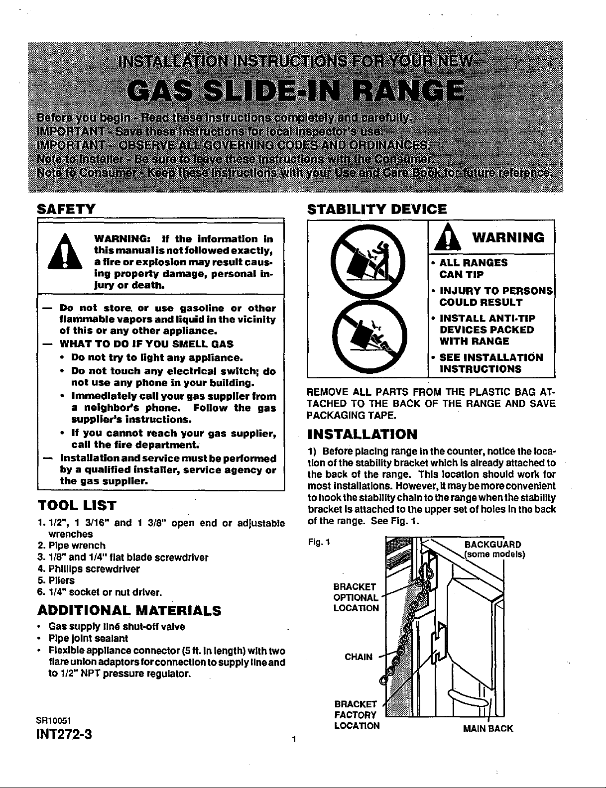
1) Beforeplaclng range ln the counter, noUcatheloca-
tion of the stability bracket which Is already attached to
the back of the range. This location should work for
most Installations. However, It may be more convenient
to hook the stability chain to the range when the stability
bracket Is attached to the upper set of holes In the back
of the range. See Fig. 1.
Fig. 1 BACKGUARD
BRACKET
OP_ONAL"
LOCA_ON
CHAIN
BRACKET
FACTORY
SR10051 LOCATION MAINBACK
INT272-3 1
Page 2
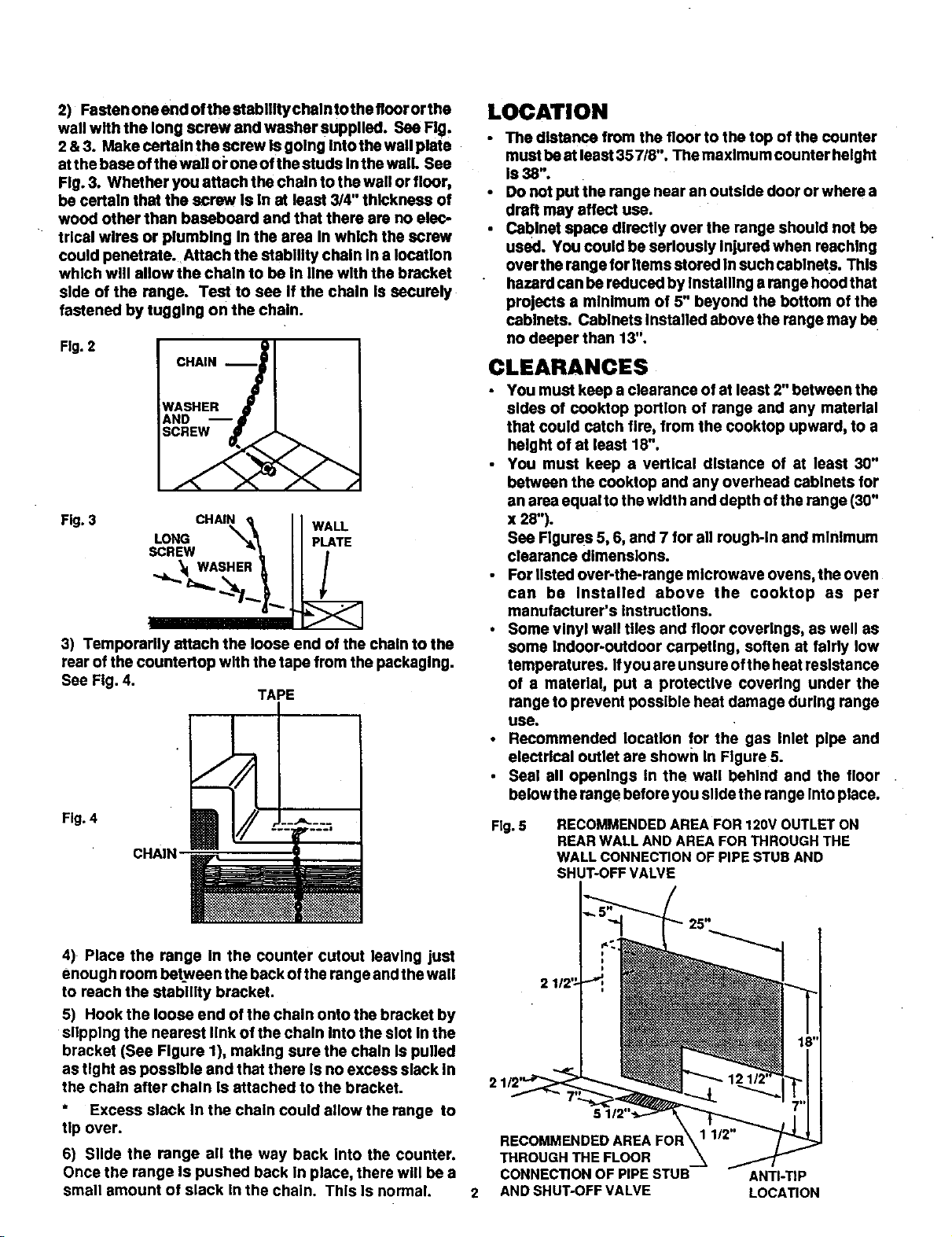
2) Fasten ono end ofthe stabllltychalntothe flnor orthe
wall with the long screw and washer supplied. See Fig,
2 & 3. Make certain the screw Is going Into the wall plate
atthe base of the wall oi"oneof the studs Inthe wall. See
Fig. 3. Whether you attach the chain to the wall or floor,
be certain that the screw Is In at least 3/4" thlcknese of
wood other than baseboard and that there are no elec-
trical wires or plumbing In the area In which the screw
could penetrate. Attach the stablllty chain In a location
which will allow the chain to be In line wlth the bracket
side of the range. Test to see If the chain Is securely
fastened by tugging on the chain.
Fig. 2
CHAIN_-_
WASHER 4r I
AND -- i I
Fig. 3 CHAIN _ WALL
WAS
3) Temporarily attach the loose end of the chain to the
rear of the countertop with the tape from the peckaglng.
See Fig. 4.
Fig. 4
TAPE
LOCATION
The distance from the floor to the top of the counter
must be at least 35718". The maximum counter height
IS38".
DOnot put the range near an outside door or where a
draft may affect use.
Cabinet space directly over the range should not be
used. You could be seriously Injured when reaching
over the range for items stored in such cablnets. This
hazard can be reduced by Installing a range hoodthat
projects a minimum o1 5" beyond the bottom of the
cabinets. Cabinets Installed above the range may be
no deeper than 13".
CLEARANCES
• You must keep a clearance of at least 2" between the
sides of cooktop portion of range and any matarlal
that could catch fire, from the cooktop upward, to a
height of at least 18".
You must keep a vertlcal distance of at least 30"
between the cooktop and any overhead cabinets for
an area equal to the width and depth of the range (30"
x 28").
See Figures 5, 6, and 7 for all rough-in and minimum
clearance dimensions.
• For listed over-the-range microwave ovens, the oven
can be Installed above the cooktop as per
manufacturer's Instructions.
• Some vinyl wall tiles and floor coverings, as well as
some Indoor-outdoor carpeting, soften at fairly low
temperatures. Ifyou are unsure ofthe heatresistance
of a materia!, put a protective covering under the
range to prevent possible heat damage during range
use.
• Recommended location for the gas Inlet plpe and
electrlcal outlet are shown In Figure 5.
• Seal all openings In the wall behind and the floor
belowthe range before you slide the range Into place.
Fig.5
RECOMMENDED AREA FOR 120V OUTLET ON
REAR WALL AND AREA FOR THROUGH THE
WALL CONNECTION OF PIPE STUB AND
SHUT-OFF VALVE
4) Place the range In the counter cutout leaving just
enough room between the back of the range and the wall
to reach the stability bracket.
5) Hook the loose end of the chain onto the bracket by
slipping the nearest link of the chain Into the slot In the
bracket (See Figure 1), making sure the chain Is pulled
as tight as possible and that there Is no excess slack In
the chain after chain is attached to the bracket.
* Excess slack In the chain could allow the range to
tip over.
6) Slide the range all the way back Into the counter.
Once the range Is pushed back In place, there will be a
small amount of slack In the chain. This Is normal.
THROUGH THE FLOOR
CONNECTION OF PIPE STUB ANTI-TIP
AND SHUT-OFF VALVE LOCATION
2
Page 3
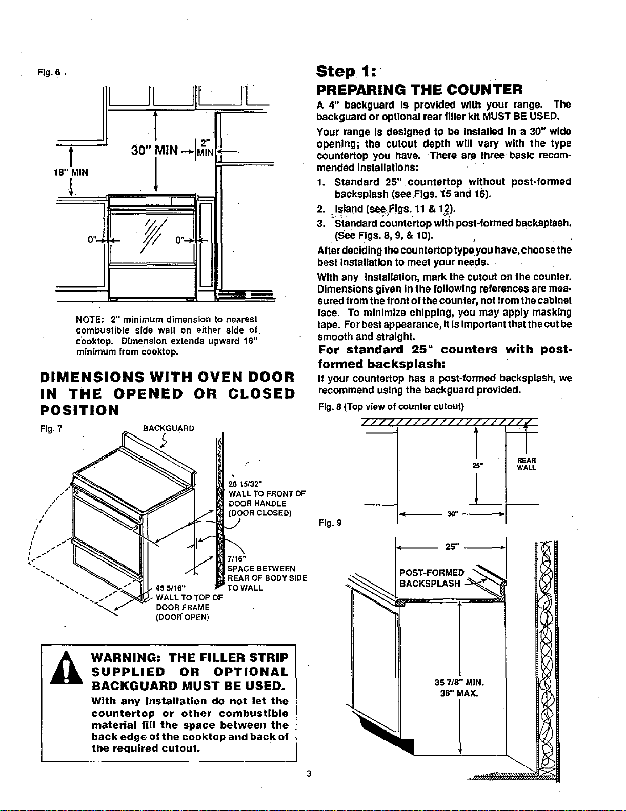
Fig.6
L
T
18" MIN
l
I
NOTE: 2" minimum dimension to nearest
combustible side wall on either side of.
c0oktop. Dimension extends upward 18"
minimum from cooktop.
DIMENSIONS WITH OVEN DOOR
IN THE OPENED OR CLOSED
POSITION
Fig. 7 BACKGUARD
Step 1:
PREPARING THE COUNTER
A 4" backguard Is provided with your range. The
backguard or optional rear lifter kit MUST BE USED.
Your range Is designed to be Installed In a 30" wide
opening; the cutout depth will vary with the type
countertop you have. There are three basic recom-
mended Installations: =_
1. Standard 25" countertop without post-formed
backsplash (see Figs. 15 and !6).
2. Island (seeFIgs. 11 & 12).
3. Standard countertop with post-formed backsplash.
(See Figs. 8, 9, & 10).
After decldln g the cou ntertop type you have, choose the
best installation to meet your needs.
With any Installation, mark the cutout on the counter.
Dimensions given In the following references are mea,
sured from the front of the counter, not from the cabinet
face. To minimize chipping, you may apply masking
tape. For best appearance, it Is important that the cut be
smooth and straight.
For standard 25" counters with post.
formed backsplash:
It your countertop has a post-formed backsplash, we
recommend using the backguard provided.
Fig. 8 (Top view of counter cutout)
//////////f/////,
J
//,/
//
/
/
, II1-
$
7
",. , 45 5/16"
_- , WALL TO TOP OF
_ WARNING: THE FILLER STRIP
SUPPLIED OR OPTIONAL
BACKGUARD MUST BE USED.
With any installation do not let the
countertop or other combustible
material fill the space between the
back edge of the cooktop and back of
the required cutout.
DOOR FRAME
(DOON OPEN)
.J
28 15/32"
WALL TO FRONT OF
DOOR HANDLE
(DOOR CLOSED)
7/16"
SPACE BETWEEN
REAR OF BODY SIDE
TO WALL
Fig. 9
-- 30' I --
25 °l __
_OST-FORMED__
BACKSPLASH--_
357/8"MIN.
38" MAX.
, I
l
REAR
WALL
3
Page 4
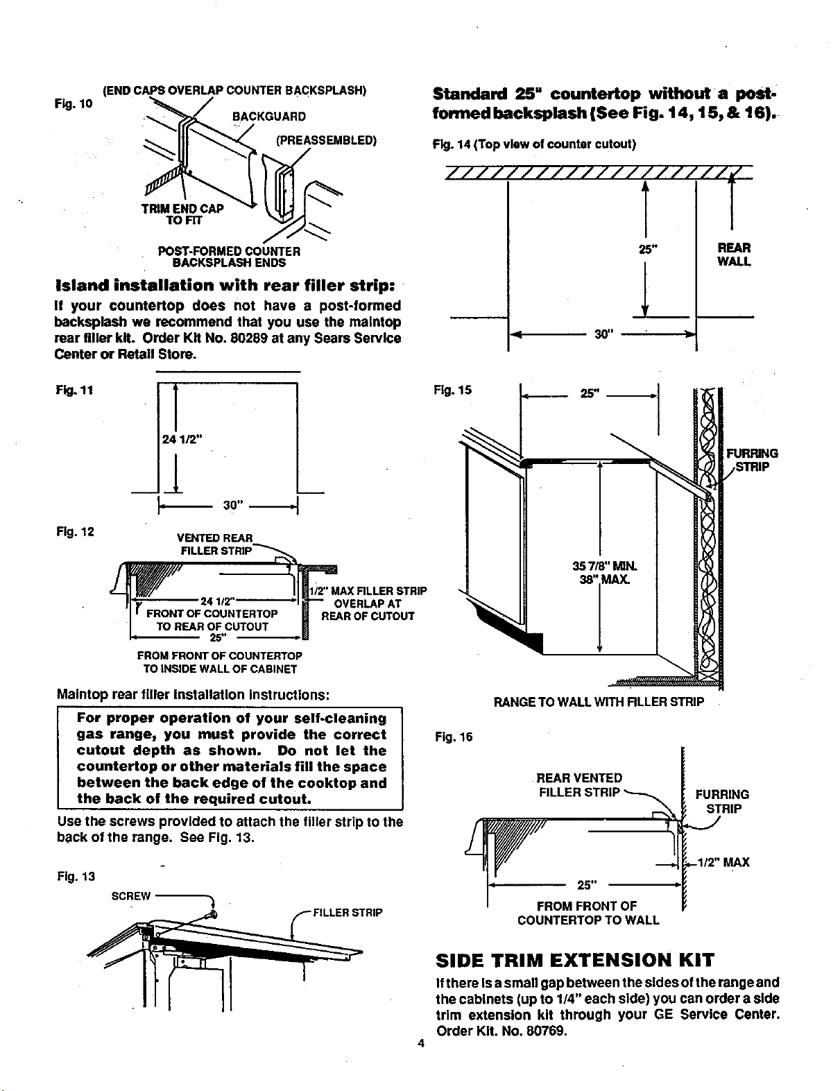
(END CAPS OVERLAP COUNTER BACKSPLASH)
F_g.10 formed backsplash (See Fig. 14, 15, & 16).
•_ BACKGUARD
Standard 25" countertop without a post,
(PREASSEMBLED)
TRIM END CAP
TOFIT
POST-FORMED COUNTER
BACKSPLASH ENDS
Island installation with rear filler strip:
If your countertop does not have a post-formed
backsplash we recommend that you use the maintop
rear filler kit. Order Kit No. 80289 at any Sears Service
Center or Retail Store.
Fig. 11
[
24 1/2"
30 °l
Fig. 12
VENTED REAR
FILLER STRIP'_
Fig. 14 (Top view of counter cutout)
////////I//////////J
T l
25" REAR
W,M.L
FUR_NG
r_ 24ll_'--------I _--- OVER_PAT
I I FRONTOFCOUNTERTOP m REAR OF CUTOUT
I TO REAR OF CUTOUT
I,I- 25" -Pl_
FROM FRONT OF COUNTERTOR
TO INSIDE WALL OF CABINET
Maintop rear filler Installation instructions:
For proper operation of your self.cleaning
gas range_ you must provide the correct
cutout depth as shown. Do not let the
countertop or other materials fill the space
between the back edge of the cooktop and
the back of the required cutout.
Use the screws provided to attach the filler strip to the
b;_ckof the range. See Fig. 13.
Fig. 13
SCREW ,_
RANGE TO WALL WITH RLLER STRIP
Fig. 16
REAR VENTED
FURRING
FILLER STRIP "_
25"
FROMFRONTOF
COUNTERTOPTO WALL
STRIP
,-1/2" MAX
SIDE TRIM EXTENSION KIT
Ifthere Is a small gap between the sides of the range and
the cabinets (up to 1/4" each side) you can order a side
trim extension kit through your GE Service Center.
Order Kit. No. 80769.
4
Page 5

Step 2:
ELECTRICAL CONNECTIONS
See Fig. 5 for compatible electrical locations.
Call your Electric Company and ask which codes apply
In your area. If there are no codes, you must follow the
NATIONAL ELECTRICAL CODE, ANSI/NFPA NO. 70-
Latest Edition. You can get a copy by writing:
National Fire Protection Association
Batterymarch Park
Quincy, MA 02269
The range cord has a three prong plug and must be
plugged Into a properly grounded three hole outlet. The
outlet must be In a standard 120 Volt, 60 Hertz AC
household circuit.
cut or remove the grounding prong
from the range cord. Failure to
J _, DO not under any circumstances J
Improper grounding can affect spark Ignition on models
so equipped.
If you do not have a grounded three hole outlet, have an
electrician change your old outlet or install a new one.
To temporarily use a properly polarized and grounded
two hole outlet until a grounded three hole outlet can be
Installed, a grounding adapter plug may be used. Have
an electrlclen test the outlet to be sure it meets require-
ments.
provide proper polarization may
cause shock and fire hazard.
Step 3:
GAS CONNECTIONS:
See Fig. 5 for compatible gas locations.
WARNING:
The conversion kit must be installed
by a qualified service technician in
accordance with the manufacturer's
instructions and all codes and
requirements of the authority having
jurisdiction.
Failure to follow instructions could
result in serious injury or property
damage. The qualified agency
performing the work assumes
responsibility for the conversion.
Call your gas supplier and ask which codes apply In
your area. If there are no codes, you must follow the
NATIONAL FUEL GAS CODE, ANSI/Z223.t-Latest Edi-
tion. You can get a copy by writing:
American Gas Assoclstlon
1515 Wilson Boulevard
Arlington (Rosslyn), VA 22209
Install a manual shut-off valve In the gas supply line In
an easily eccesslble location. Know how and where to
shut off the gas supply to the range.
Shut off gas supply before removing an old range.
Leave it off unUl hookup of new range Is finished.
Because solid pipe restricts moving the range, we rec-
ommend use of an A.G.A. certified metal appliance
connector. Never reuse an old connector when
installing a new range.
Before making gas connections, make sure that the
oven shut-off lever (visible at back of range) is in the
open position. See Figure 17.
F_.17 GAS SUPPLY
TO OVEN
The range, as shipped from the fac-
tory, can only be operated with natu-
ral gas. Do not try to operate it with
L.P. (bottled) gas. High flames and
toxic fumes could cause serious in-
jury. If you wish to use your range with
L.P. gas, you must purchase an L.P.
Conversion Kit and have it installed by
a qualified installer.
L.P. CONVERSION KIT
Your range is shipped from the factory set to operate
only with Natural Gas.
If you wish to use your range with Liquefied Petroleum
Gas, you can have your salesperson order Kit 80075 for
Model 36725 or Kit 80079 for Model 36729.
HOMEOWNER:
Do not attempt this conversion yourself!
SHUT-OFF LEVER
SHOWN IN
OPEN POSITION
Install 1/2" flare union adaptor to the 1/2" NPT elbow on
pressure regulstor. Connect flexible appllence connec-
tor to flareunlon. Move range intoapproximate position
and connect flexible connector to gas supply line with
proper flare union adaptor. See Fig. 19.
To prevent gas leaks, put a pipe joint sealant on all male
threads.
When you are finished making connections, be surethat
all range knobs are turned to OFF before you open the
main gas supply valve.
5
GAS SUPPLY
TO TOP
BURNERS
PRESSURE
REGULATOR AS
SEEN FROM
FRONTOF RANGE
Page 6
Step 4:
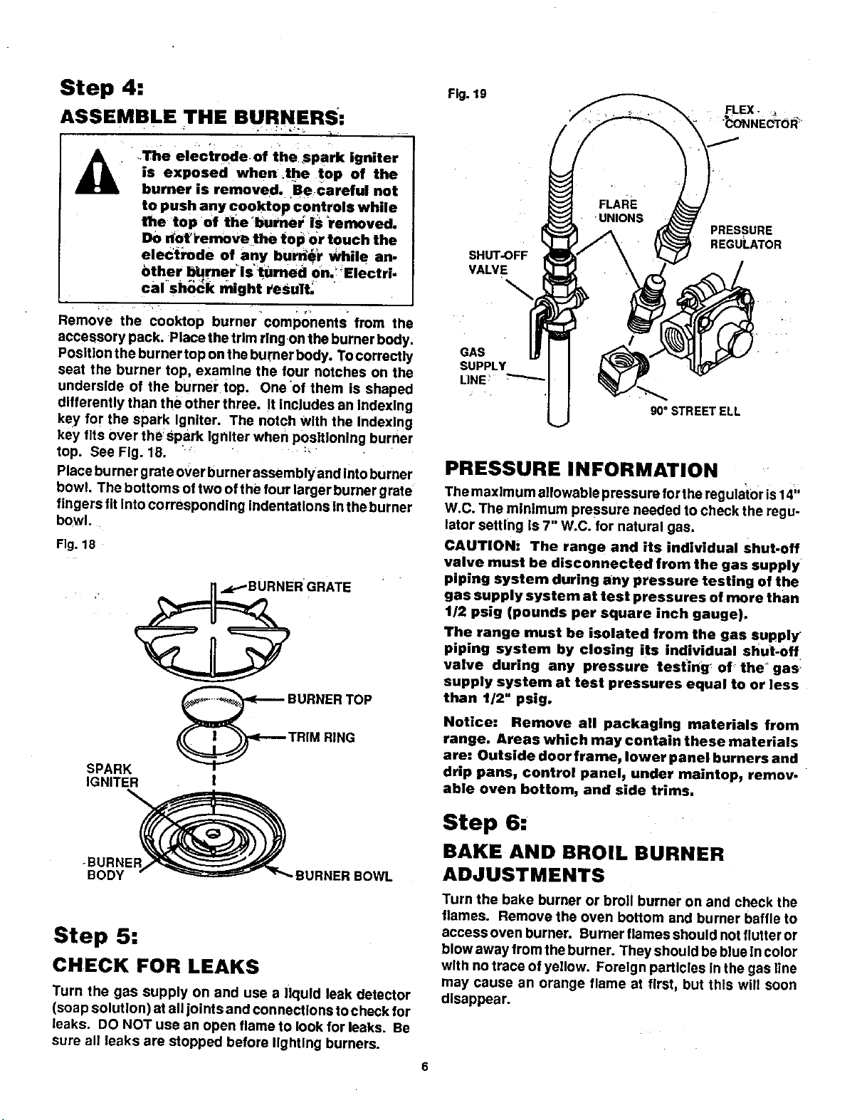
ASSEMBLE THE BURNERS:
Fig. 19
_ The electrode of thespark igniter
accessory pack. Placethe trim rlng on the burner body.
Position the burner top on the burner body. To correctly
seat the burner top, examine the four notches on the
underside of the burner top. One of them Is shaped
differently than the other three. It IncJudes an indexing
key for the spark Igniter. The notch with the Indexing
key flts over th__spark Igniter when positioning burner
top. See Fig. 18. :'
Place burner grate over burner assemblyand intoburner
bowl. The bottoms of two of the four larger burner grate
fingers fit into corresponding indentations inthe burner
bowl.
Fig. 18
SPARK
IGNITER
is exposed when _the top of the
burner is removed. Becareful not
to push any cooktop controls while
tlhe top of the bumel: iS renlmved.
Do dot_Vemov_ the top Or touch the
electrode of any burn_'r While an_
bther bbrner_is't'umed onJ Eiectri
cal sh_k ndght reSult.
burner components theRemove the cooktoP _ from
ER'GRATE
BURNERTOP
TRIMRiNG
!
PRESSURE
REGULATOR
SHUT-OFF
VALVE
GAS
SUPPLY
LINE:
90° STREET ELL
PRESSURE INFORMATION
The maximum allowable pressure forthe regulator is14"
W.C. The minimum pressure needed to check the regu-
lator setting Is 7" W.C. for natural gas.
CAUTION: The range and its individual shut.off
valve must be disconnected from the gas supply
piping system during any pressure testing of the
gas supply system at test pressures of more than
1/2 psig (pounds per square inch gauge).
The range must be isolated from the gas supply
piping system by closing its individual shut-off
valve during any pressure testing _of' the _gas,
supply system at test pressures equal to or less
than t/2" psig.
Notice: Remove all packaging materials from
range. Areas which may contain these materials
are: Outside door frame, lower panel burners and
drip pans, control panelj under maintopj remov.
able oven bottom, and side trims.
-BURNER
BODY .BURNER BOWL
Step 5:
CHECK FOR LEAKS
Turn the gas supply on and use a liquid leak detector
(sospsolution) at all joints and connections to check for
leaks. DO NOT use an open flame to look for leaks. Be
sure all leaks are stopped before lighting burners.
Step 6:
BAKE AND BROIL BURNER
ADJUSTMENTS
Turn the bake burner or broil burner on and check the
flames. Remove the oven bottom and burner baffle to
access oven burner. Burner flames should not flutter or
blow away from the burner. They should be blue In color
with no trace of yellow. Foreign particles In the gas llne
may cause an orange flame at first, but this will soon
disappear.
Page 7

Fig.20
Fig. 22 ORIRCE
RTrlNG
COVER
UAJ,
YELLOW FLAMES
CALL FOR SERVICE
"a"
YELLOW
TIPPING
NORMAL FOR LP GAS
I_Cll
SOFT BLUE FLAMES
NORMALFORNATURALGAS
If burner flames look like "A", call for service. Normal
burner flames should look like =B"or =C", depending on
the type of gas you use.
With LP gas, some yellow tlpplng on outer cones Is
normal.
Foreign partlcles In the gas line may cause an orange
flame at first, but this will soon disappear.
If the flames are yellow or flutter, open the air shutter
more.
If the flames blow away from the burner, close the
shutter more. Burner flames should be checked fre-
quently.
To adjust air shutters:
Bake/broil burners, (see figures below)--use a screw-
driver to loosen the air shutter screw. Adjust airshutter.
Retlghten the air shutter screw.
*The broil burner Is located and accessible In the top
rear of the oven.
Fig. 21
BURNER
AIR
SHUTTER
AIR
SHUTTER
SCREW
AIR
SHUTrER
SCREW
Check the In ner cone of the flame. It should be between
1/2" and 3/4" long for the oven/broiler burners.
Fig. 23
INNER CONE
112"to3/4" J"
11F'L OVE BROiLER
f OF FLAME
AI
I
NOTE: After the air
shutter ad-
justments
have been
made to the
burners, be
sure to rein.
stall the ori.
lice fitting
cover.
Step 7:
COOKTOP BURNERS
Turn each burner full on. Flames should be blue In color
with no trace of yellow. Forelg n parUcles In the gas line
may cause an orange flame at first but this will soon
disappear. The burner flames should not flutter or blow
away from the burner. The Inner cone of the flame
should be between 1/2" and 3/4" long.
Fig. 24
COOKTOP
112"to3/4"
*The bake burner is located and accasslble by removing
the oven bottom, baffle (flame spreader), and the orifice
fitting cover.
NOTE: Removal of the oven door will make this
easier. To remove the door, open to the
stop position. Grasp both sides and lift
straight off the hinges.
NOTE: The cooktop burners are equipped with an
auto-relight feature which will light or
rel|ght the burners with the control knob
in any position except off. Drafts from
fans, open windows, or overhead vents
may disrupt the burner flame, resulting in
sparking of the top burner electrodes af-
ter the bumer has lit. See use and care
manual for additional information.
Page 8

Step 8:
LEVELING
For proper baking results, the range must be leveled.
The height of the range must also be adjusted to the
height of the counter. To do this:
1. Install theoven racks (ssa cleaning and care section
In the manual for Instructions and additional
Information).
2. Usa 1 3/8" open end or adjustable wrench to equatly
back out the tour leg levelers until the flanges (rims)
on the sides of the cooktop are above the top of the
counter.
3. Place range where It will he Installed. Put a spirit
level or a glass measuring cup partially filled with
water on one of the oven racks.
4. Use the wrench to adjust the leg levelers.
Fig.25
SPIRIT
LEVEL
Fig. 26
//
3"MAX. HEIGHT
This gap Isvery Important to the proper venUlstlon of the
range and must be maintained when treating the appear-
ance of the toe space.
The following Is a suggested method of making afiller for
the toe space when the legs are extended as mentlened
before.
After the range Is Installed with the longer legs and Is In
position and level, measure from the bottom of the
bodyslde to the floor. This will be the required belght of
the toe space filler. See Fig. 26. This height may range
from 2 1/16"to 3". Any height lessthan 2 1/16" may not
be visually objectionable and not need the filler.
"o." ]1// //
Step 9:
Double check to make sure anti-tip chain Is connected.
See pages I and 2.
IMPORTANT INSTALLATION IN-
STRUCTIONS FOR RANGES USED
WITH COUNTERTOP HEIGHTS UP
TO 38"
";'heheight of the range must beadjusted to the counter-
top height. For countertop heights greater than 37",
addltlenal measurements may need to be taken as
detailed below.
When the range Is elevated to the maximum height,
there Is a large space between the bottom of the range
and the floor, referred to as the toe space. This may be
visually objectionable. The legs should not be extended
any further than to provide a maximum of 3" toe space.
See Fig. 26.
The range Is deslg ned to provide amlBlmu_
at the bottom of the range. See Fig.27. (Example: When
legs are screwed all the way IntOlhLrb_'_-dT_ _
"MIN. HEIGHT
Build the filler as shown In Fig. 26. Make sure to provide
the 3/4" gap at the top and the 5/16" gap at the bottom.
These gaps will provide the proper ventilation as men-
tioned before.
If you wish to attach the filler to the floor or adjacent
cabinets, use screws or other removable fasteners, so
that the range can be readily removed if necessary.
Fig.28
J
USE 114" TO 1/2"
MATERIAL FINISHED
TO MATCH TOE AREA
OF CABINETS
SR10051
INT272-3 8
Printed in LaFayette, Georgia
 Loading...