

Page 1

GE
WWW.UKPANELS.COM
Security
FASD700 aspirated smoke detector
installation manual
version 3-0 / january 2005
Page 2

WWW.UKPANELS.COM
http://www.geindustrial.com/ge-interlogix/emea
© 2005 GE Interlogix B.V.. All rights reserved. GE Interlogix B.V. grants the right to reprint this manual for internal use only. GE
Interlogix B.V. reserves the right to change information without notice.
FASD700 aspirated smoke detector – Installation manual 2
Page 3

WWW.UKPANELS.COM
C
ONTENTS
1
Introduction............................................................................................................................................ 4
1.1 Product description ....................................................................................................................... 4
2
Installation.............................................................................................................................................. 5
2.1 Electrical connections ................................................................................................................... 5
2.2 Detector installation....................................................................................................................... 6
2.3 Panel installation ........................................................................................................................... 7
2.4 Pipe installation ............................................................................................................................. 7
2.5 External connections..................................................................................................................... 7
3
User guide .............................................................................................................................................. 8
3.1 Selecting and programming functions........................................................................................... 8
3.2 FASD710 / FASD712 operation.................................................................................................... 9
3.3 FASD715 / FASD717 operation.................................................................................................. 11
4
Maintenance......................................................................................................................................... 14
5
Technical specifications..................................................................................................................... 15
3 FASD700 aspirated smoke detectors – Installation manual
Page 4

WWW.UKPANELS.COM
1 I
NTRODUCTION
1.1 Product description
The FASD700 range of aspirated smoke detectors includes:
FASD710 and FASD712 panels (conventional or analogue addressable detectors).
FASD715 and FASD717 panels (laser detectors).
All panels are IP50 rated. An optional IP65 rating is available to allow use in many harsh
environments and where regular hosing is performed.
1.1.1 FASD710 and FASD712 panels
FASD710 and FASD712 panels have the following features:
Installation of up to two conventional or analogue addressable detectors (not
supplied) providing the ability for failsafe redundancy or mixed detection strategies.
High performance aspirator and flow monitoring circuit. The flow level is displayed on
a 10 element bar graph with adjustments for high and low flow thresholds. Flow
failure is reported to the central panel as a device fault on the primary detector.
In-line air filter to remove dust particles from the air sample. This is housed in a
removable transparent cartridge enabling rapid inspection and maintenance.
Closed loop sampling (the exhausted air can be completely returned to the sampled
area) making in ideal for use in small spaces.
1.1.2 FASD715 and FASD717 panels
FASD715 and FASD717 panels have the following features:
Two laser detectors (supplied) in single or two-channel configurations. This gives a
large monitored area using sampling holes in the place of point detectors. The
FASD717 has two pipes and can cover twice the area of the FASD715.
High performance aspirator and flow monitoring circuit to ensure a constant,
monitored flow level which can be displayed on a 10 element bar graph with
adjustments for high and low flow thresholds. Three alarm levels give warnings at
their pre-set levels.
In-line air filters to remove dust particles from the air samples. These are housed in
removable transparent cartridges enabling rapid inspection and maintenance.
RS232 Modbus port to download all the data that is logged within the unit. This can
then be used to look at events or trends over a period of time.
FASD700 aspirated smoke detector – Installation manual 4
In addition to the above FASD715 panels also have the following features
Closed loop sampling whereby the exhausted air can be completely returned to the
sampled area.
Can be configured to require both detectors to go into alarm to avoid false discharges
of suppression systems. By using two independent detectors this removes the need
for two separate systems.
Page 5
WWW.UKPANELS.COM
2 I
2.1 Electrical connections
WARNING! The power supply should not be connected until all other
connections have been completed.
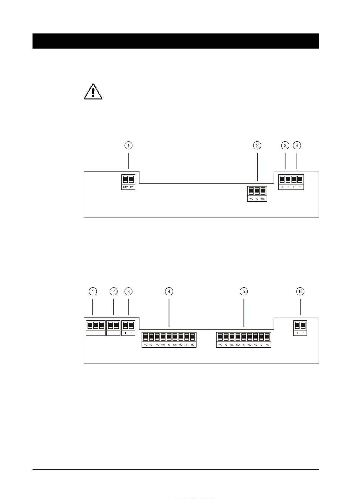
To access the PCB connectors the inner cover of the panel must be removed.
Figure 1: PCB connectors for FASD710 / FASD712 panels
NSTALLATION
1. Battery
2. Fault relay
3. Loop in
4. Loop out
Figure 2: PCB connectors for FASD715 / FASD717 panels
1. Mains power supply (left to right: earth, neutral, live)
2. Temperature sensor
5 FASD700 aspirated smoke detectors – Installation manual
3. Battery
4. Channel 1 relays (left to right: fire, action, fault)
5. Channel 2 relays (left to right: fire, action, fault)
6. External reset
Page 6
WWW.UKPANELS.COM
2.2 Detector installation
Up to two detectors may be installed.
For the FASD710 / FASD712 panels conventional or analogue addressable detectors
may be used (not supplied).
For the FASD715 / FASD717 panels laser detectors are supplied.
2.2.1 Connecting detectors
To connect the detector(s):
1. Remove the panel front cover.
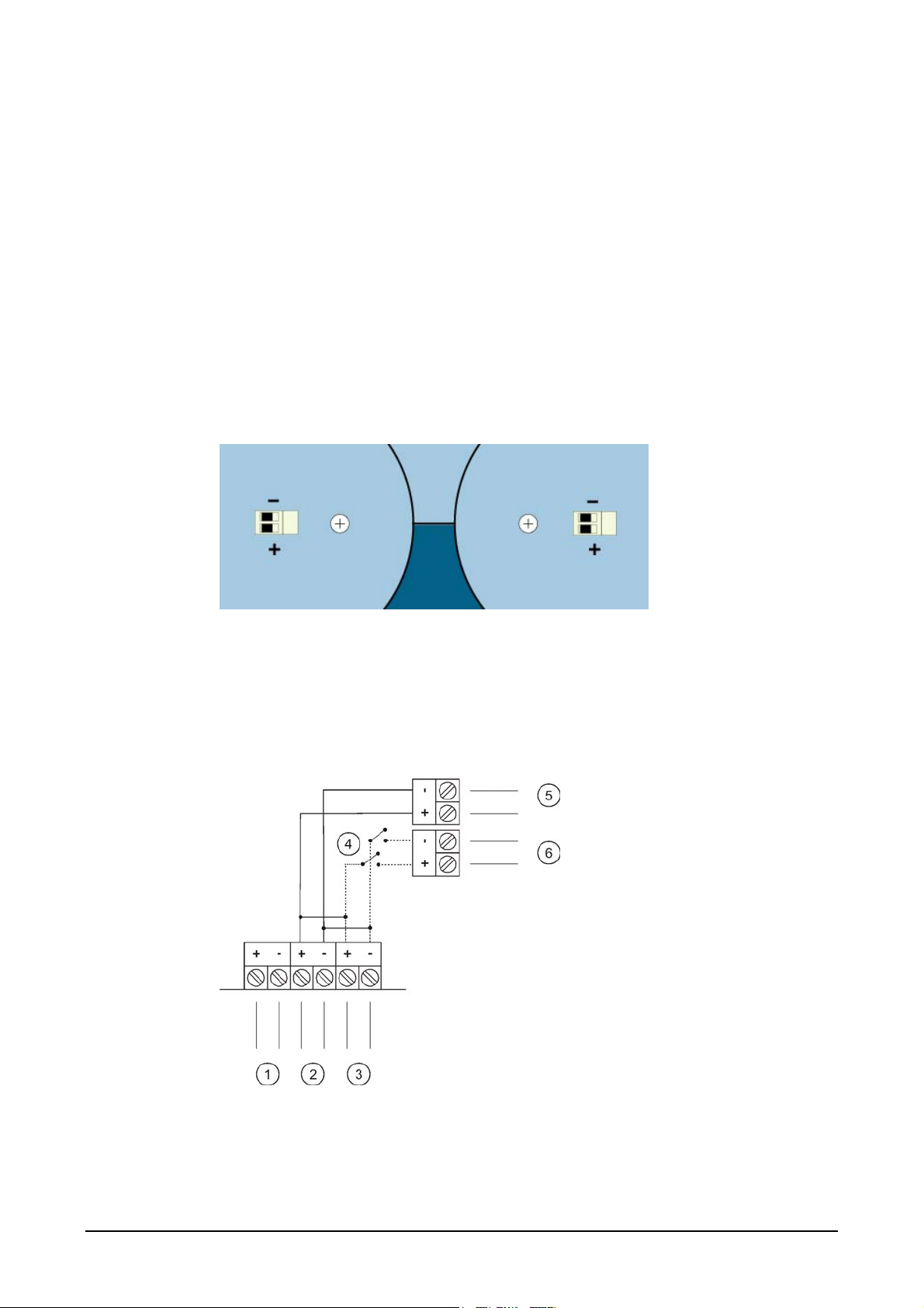
2. Connect the loop terminals of the detector(s) to the 2-way connector block(s) on the
inner panel (see Figure 3: Panel detector connection).
Figure 3: Panel detector connection
2.2.2 Configuration for analogue addressable detectors (FASD710 / FASD712)
Figure 4: FASD710 / FASD712 analogue addressable detector connection
A flow fault is reported as a device fault on detector 1.
FASD700 aspirated smoke detector – Installation manual 6
1. To 24 VDC power supply
2. Loop in to fire panel
3. Loop out to fire panel
4. Relay contact
5. To detector 1
6. To detector 2
Page 7

WWW.UKPANELS.COM
Note:
For detector connection details and for alarm / end-of-line resistor values refer to the
detector / fire panel manual.
In the event of a fault on the FASD710 / FASD712 panel, the relay on the main PCB
will open the fault monitor line "DET1". This will give the fault signal on the fire panel.
2.3 Panel installation
The panel should be secured to a suitable surface using the 4 corner fixing points.
2.4 Pipe installation
Note the following:
ABS, UPVC, copper or stainless steel pipe may be used.
Pipe with an outer diameter of 25 mm or 26.7 mm may be used. An adapter is
required for used with 25 mm pipe.
Pipe lengths are cut as required and joined by sockets (permanent), solvent welded
or socket unions (removable).
Smoke tests should be performed before planning and installing the pipe network.
For pipe installation guidelines refer to the FHSD700 Ducts Installation
manual.
CAUTION! Do not use T-joints in low-pressure wide-bore systems. These
make pipe design and air-flow calculation difficult to predict accurately.
2.5 External connections
The panels allow the following external connections.
2.5.1 FASD710 / FASD712 panels
Mains supply
24 VDC
External loop disconnect alarm relay (optional)
I/O module (optional)
2.5.2 FASD715 / FASD717 panels
Mains supply
24 VDC
Alarm relays
RS232
Isolate
External loop disconnect alarm relay (optional)
I/O module (optional)
7 FASD700 aspirated smoke detectors – Installation manual
Page 8

WWW.UKPANELS.COM
3 U
SER GUIDE
3.1 Selecting and programming functions
Panels are programmed using the SELECT and CHANGE keys located on the side of the
unit.
1. Press and hold the SELECT and CHANGE keys simultaneously for 1 second to
initialise function selection.
2. Press and hold the SELECT key to step through each function. Each LED on the
front panel will be illuminated sequentially. Keep the SELECT key pressed until the
LED for the function you wish to change is selected.
3. Press and hold the CHANGE key to modify the setting.
A complete list of available functions for each panel is available in sections
3.1.1 Code entry
3.2.2 FASD710 / FASD712 functions and 3.3.2 FASD715 / FASD717
functions.
The code 510 must be entered to allow any function change.To enter the code:
1. Initialise function selection (see above) and select the Code entry LED. Press
change. The Code entry LED will flash.
2. Press and hold the CHANGE key until the number 5 LED on the bar graph is
illuminated.
3. Press the SELECT key.
4. Repeat steps 1 to 3 until the complete access code (510) has been entered.
The Unlocked LED will flash when the code has been entered correctly.
FASD700 aspirated smoke detector – Installation manual 8
Page 9
WWW.UKPANELS.COM
3.2 FASD710 / FASD712 operation
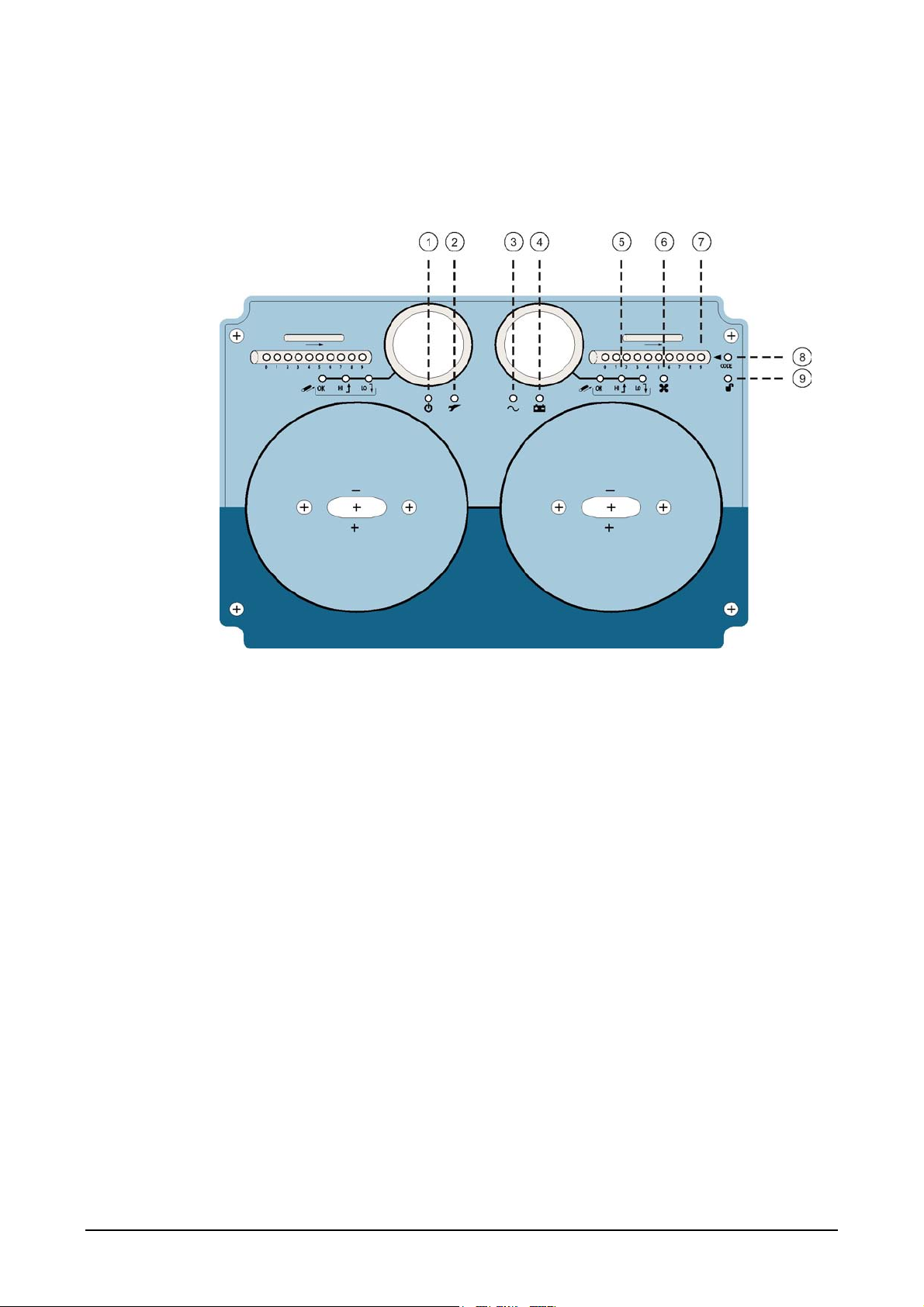
3.2.1 Display LEDs
Figure 5: FASD710 / FASD712 front panel and display LEDs
1. Power
2. General fault
3. Mains fault
4. Battery low
5. Airflow ok / high / low
6. Fan fault
7. Bar graph of airflow speed
8. Code entry
9. Unlocked
9 FASD700 aspirated smoke detectors – Installation manual
Page 10

WWW.UKPANELS.COM
3.2.2 FASD710 / FASD712 functions
Access the required funtion as described in section 3.1 Selecting and programming
functions. The relevant LED will flash continuously to indicate the active function.
Table 1: FASD710 / FASD712 functions
Function Description
3.2.3 Unit alarms
1
2 Set fan speed. The Power LED flashes.
3
4
5
6
7
8
Code entry. See section 3.1.1 Code entry. The Code entry LED
flashes.
Set sensitivity of bar graph to changes in airflow velocity. The Flow
OK LED flashes.
Select the bar graph LED segment above which the Flow HI LED
will be illuminated. The Flow HI LED flashes.
Select the bar graph LED segment below which the Flow LO LED
will be illuminated. The Flow LO LED flashes.
Select Mains/Battery fault detection. The general Fault LED flashes
(Mains / Battery LED flashes if selected)
Calibrate flow sensors at zero and selected airflow speed. The Fan
fault LED flashes (Fan and Power LEDs flash during calibration).
Exit function selection and return to normal mode. A 20 second timeout function will also exit calibration mode.
Airflow or Power fault (1 relay).
FASD700 aspirated smoke detector – Installation manual 10
Page 11
WWW.UKPANELS.COM
3.3 FASD715 / FASD717 operation
3.3.1 Display LEDs
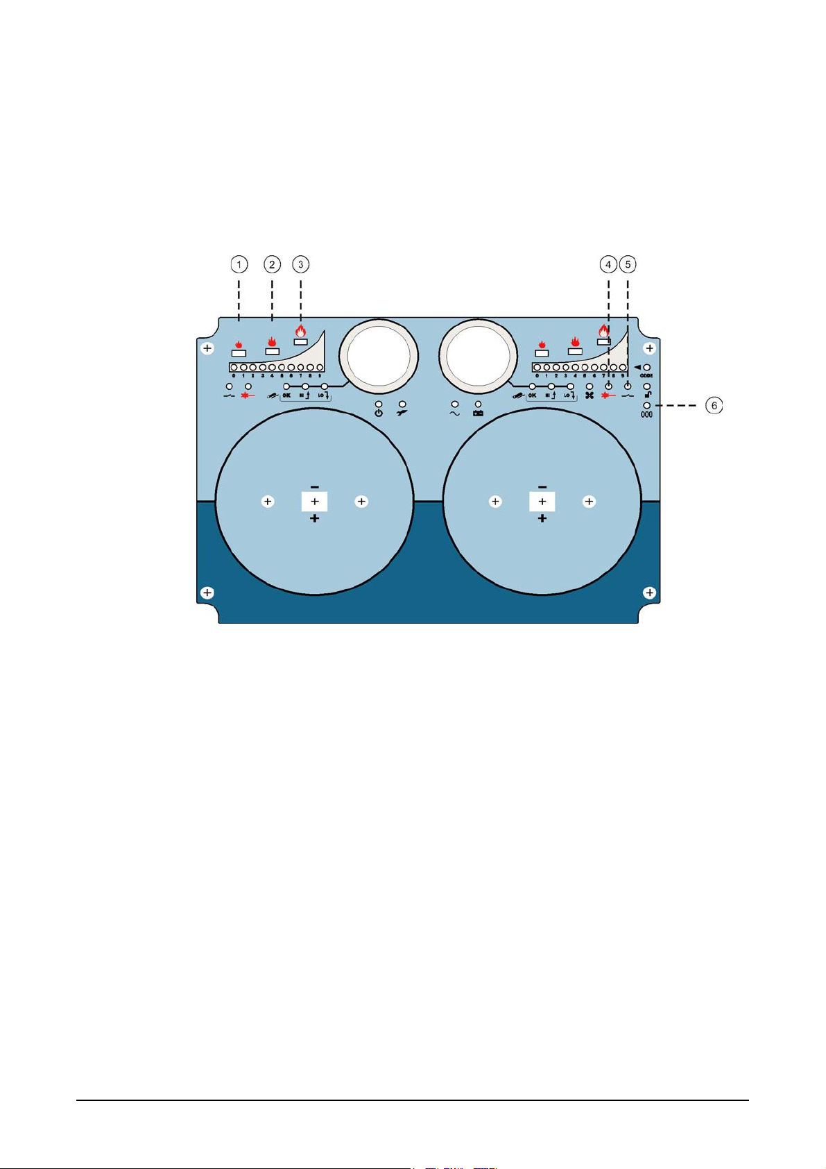
The FASD715 / FASD717 panels use the same interface and LEDs as the FASD710 /
FASD712 panels (see Figure 5) with the following additions.
Figure 6: FASD715 / FASD717 front panel and display LEDs
1. Alert alarm
2. Action alarm
3. Fire alarm
4. Smoke detector fault
5. Isolate
6. Reset
11 FASD700 aspirated smoke detectors – Installation manual
Page 12

WWW.UKPANELS.COM
3.3.2 FASD715 / FASD717 functions
Access the required funtion as described in section 3.1 Selecting and programming
functions. The relevant LED will flash continuously to indicate the active function.
Table 2: FASD715 / FASD717 functions
Function Calibration mode
1
2
3
4 Set fan speed. The Power LED flashes.
5
6
7
8 Set smoke detector ALERT alarm threshold. The Alert LED flashes.
9
10 Set smoke detector FIRE alarm threshold. The Fire LED flashes.
11
Code entry. See section 3.1.1 Code entry. The Code entry LED
flashes.
To RESET the panel press SELECT when the Reset LED is
flashing.
Select Isolate channel. The Isolate LEDs flash (constant illumination
when set).
Set sensitivity of bar graph to changes in airflow velocity. The Flow
OK LED flashes.
Select the bar graph LED segment above which the Flow HI LED
will be illuminated. The Flow HI LED flashes.
Select the bar graph LED segment below which the Flow LO LED
will be illuminated. The Flow LO LED flashes.
Set smoke detector ACTION alarm threshold. The Action LED
flashes.
Select Mains/Battery fault detection. The general Fault LED flashes
(Mains / Battery LED flashes if selected)
3.3.3 Unit alarms
CH1 FIRE; CH1 ACTION; CH2 FIRE; CH2 ACTION (4 relays).
CH1 smoke detector, airflow or power Fault (1 relay).
CH2 smoke detector, airflow or power Fault (1 relay).
12
13
Calibrate flow sensors at zero and selected airflow speed. The Fan
fault LED flashes (Fan and Power LEDs flash during calibration).
Exit function selection and return to normal mode. A 20 second timeout function will also exit calibration mode. Smoke detector level
displayed as cumulative bar graph on each display.
FASD700 aspirated smoke detector – Installation manual 12
Page 13

WWW.UKPANELS.COM
3.3.4 Bar graph levels
The bar graph on the front panel indicates the level of smoke being detected. Table 3
shows how the levels on the bar graph correspond to the smoke levels being detected.
These are also the levels at which the alarms can be set.
Table 3: Bar graph levels
Bar graph LED Obscuration % / metre
1 0.065
2 0.098
3 0.164
4 0.327
5 0.655
6 1.637
7 3.273
8 4.887
9 6.516
13 FASD700 aspirated smoke detectors – Installation manual
Page 14

WWW.UKPANELS.COM
4 M
The filter should be inspected every six months. This is housed in a removable
transparent cartridge enabling rapid inspection and maintenance
The lifespan of the filter will depend on the installation environment. A dirty filter will
reduce airflow and lower the accuracy of smoke detection.
To change the filter:
1. Remove the panel cover.
2. Remove the filter from the acrylic housing.
3. Insert the new filter.
4. Replace the panel cover.
AINTENANCE
FASD700 aspirated smoke detector – Installation manual 14
Page 15
WWW.UKPANELS.COM
5 T
Dimensions (FASD710 / FASD712) .................................................................................... 254 x 180 x 165 mm
Dimensions (FASD715 / FASD717) .................................................................................... 254 x 180 x 112 mm
Maximum number of detectors ...........................................................................................................................2
Filtration .................................................................................................................... Cartridge dust particle filter
Flow monitoring .......................... Thermal device, hi / lo thresholds, 10 element indication, loop fault reporting
Supply voltage ......................................................................................................................................... 24 VDC
Supply current (without aspirating pipe) .................................................................................................. 460 mA
Supply current (Dependant on fan speed / pipe length.).................................................................. See Table 4
Maximum pipe length (per channel) ...........................................................................................................100 m
IP rating ................................................................................................................................IP50 (IP65 optional)
Operating temperature....................................................................................................................... -10 to 60ºC
Operating humidity............................................................................................10 to 95% RH (non-condensing)
Table 4: Fan speed / supply current with 20 m pipe length and 6 mm end hole
Fan speed Supply current (mA)
9 330
8 260
ECHNICAL SPECIFICATIONS
7 200
6 160
5 125
4 100
3 75
2 60
1 50
0 50
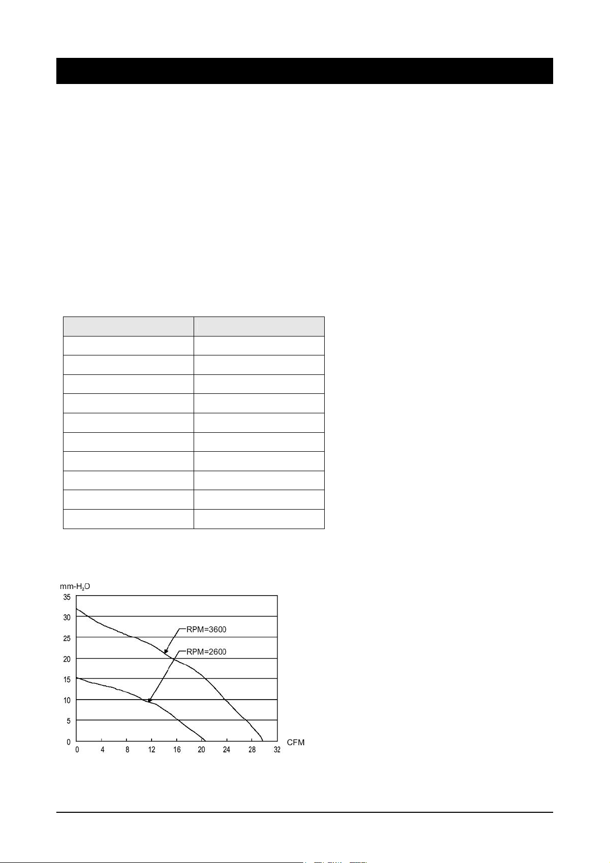
Figure 7: Static Pressure and CFM graph for fan at 2600 rpm and 3600 rpm
15 FASD700 aspirated smoke detectors – Installation manual
Page 16

WWW.UKPANELS.COM
?
1052955
 Loading...