

Page 1

GE
LISTED
Grid Solutions
F650 Digital Bay Controller
User Guide
Firmware version: 7.5x
EnerVista F650 Setup version: 7.5x
GE publication code: GEK-113000-AF
*GEK-113000AF*
Page 2

© 2017 GE Multilin Inc. All rights reserved.
GE Multilin F650 Feeder Protection System instruction manual for revision AF.
F650 Feeder Protection System, EnerVista, and EnerVista 650 family
Setup are registered trademarks of GE Multilin Inc.
The contents of this manual are the property of GE Multilin Inc.
This documentation is furnished on license and may not be reproduced in
whole or in part without the permissi
this manual is for informational use only and is subject to change without notice.
Part number: GEK-113000-AF (June 2017)
on of GE Multilin. The content of
Page 3

GE
Grid Solutions
F650 Digital Bay Controller
Table of Contents
1 GETTING STARTED 1.1 Important procedures ..................................................................................... 1-1
1.1.1 Cautions and warnings ....................................................................................................... 1-1
1.1.1.1 General cautions and warnings.................................................................................................1-2
1.1.1.2 Communication board withdrawal/insertion...................................................................... 1-3
1.1.1.3 Magnetic module terminals.........................................................................................................1-4
1.1.2 Inspection checklist............................................................................................................... 1-5
1.1.3 Safety instructions................................................................................................................. 1-7
1.1.3.1 General safety instructions.......................................................................................................... 1-8
1.1.3.2 Warning symbols..............................................................................................................................1-9
1.2 Overview .......................................................................................................... 1-10
1.2.1 Introduction to the 650 family of relays....................................................................1-10
1.2.2 Hardware architecture ......................................................................................................1-10
1.2.2.1 F650 basic design.......................................................................................................................... 1-10
1.2.2.2 F650 signal type............................................................................................................................. 1-11
1.2.3 Communications architecture .......................................................................................1-11
1.3 EnerVista 650 Setup software......................................................................1-14
1.3.1 System requirements.........................................................................................................1-14
1.3.2 Installation...............................................................................................................................1-14
1.3.3 Connecting EnerVista 650 Setup to the F650 .........................................................1-18
1.3.3.1 Configuring an Ethernet connection .................................................................................... 1-18
1.3.3.2 Configuring the RS232 connection....................................................................................... 1-18
1.4 650 hardware .................................................................................................. 1-19
1.4.1 Mounting & wiring................................................................................................................1-19
1.4.2 650 communications..........................................................................................................1-19
1.4.3 Faceplate display .................................................................................................................1-20
1.4.4 Maintenance...........................................................................................................................1-21
1.4.4.1 General maintenance.................................................................................................................. 1-21
1.4.4.2 In-service maintenance.............................................................................................................. 1-21
1.4.4.3 Out-of-service maintenance .................................................................................................... 1-21
1.4.4.4 Unscheduled maintenance....................................................................................................... 1-21
1.4.5 Storage......................................................................................................................................1-21
1.4.6 Repairs.......................................................................................................................................1-22
1.4.7 Disposal.....................................................................................................................................1-22
2PRODUCT
DESCRIPTION
GEK-113000-AF F650 DIGITAL BAY CONTROLLER 1-1
2.1 F650 Overview................................................................................................... 2-1
2.2 ANSI device numbers and functions ............................................................. 2-3
Page 4

CHAPTER 1:
2.3 Other device functions .................................................................................... 2-4
2.4 Order codes ....................................................................................................... 2-5
2.4.1 CIO Modules ..............................................................................................................................2-7
2.5 Technical specifications.................................................................................. 2-8
2.5.1 Protection ...................................................................................................................................2-8
2.5.2 Control....................................................................................................................................... 2-16
2.5.3 Monitoring...............................................................................................................................2-19
2.5.4 User-programmable ..........................................................................................................2-21
2.5.5 Metering ................................................................................................................................... 2-22
2.5.6 Inputs......................................................................................................................................... 2-22
2.5.7 Real time clock......................................................................................................................2-24
2.5.8 Outputs.....................................................................................................................................2-24
2.5.9 Control power supply ........................................................................................................ 2-24
2.5.10 Communications..................................................................................................................2-25
2.5.11 Optical....................................................................................................................................... 2-27
2.5.12 Environmental.......................................................................................................................2-28
2.5.13 Packaging and weight....................................................................................................... 2-28
2.5.14 Type tests................................................................................................................................2-28
2.5.15 Approvals.................................................................................................................................2-29
2.6 External connections .....................................................................................2-30
3INTERFACES,
SETTINGS & ACTUAL
VALUES
3.1 EnerVista 650 Setup software ........................................................................ 3-1
3.1.1 Introduction...............................................................................................................................3-1
3.1.1.1 Using settings files ........................................................................................................................... 3-2
3.1.1.2 Viewing actual values..................................................................................................................... 3-2
3.1.1.3 Viewing triggered events .............................................................................................................. 3-2
3.1.1.4 Firmware upgrades......................................................................................................................... 3-2
3.1.1.5 One line diagrams............................................................................................................................ 3-2
3.1.2 Main screen ...............................................................................................................................3-3
3.1.3 Connect to the relay..............................................................................................................3-4
3.1.3.1 Computer Settings: .......................................................................................................................... 3-5
3.1.3.2 Communication Control: ............................................................................................................... 3-5
3.1.3.3 Communication Optimization:.................................................................................................... 3-5
3.1.4 File management menu ......................................................................................................3-6
3.1.4.1 Offline mode........................................................................................................................................ 3-6
3.1.4.2 Online mode........................................................................................................................................ 3-8
3.1.5 EnerVista 650 Setup menu.............................................................................................. 3-10
3.1.6 File menu .................................................................................................................................3-11
3.1.6.1 New, Open, Save, Save as, and Close ..................................................................................3-12
3.1.6.2 Configuration file converter.......................................................................................................3-13
3.1.6.3 Properties ...........................................................................................................................................3-15
3.1.6.4 Print options......................................................................................................................................3-15
3.1.6.5 Compare to settings file ..............................................................................................................3-16
3.1.6.6 PLC checksum calculation .........................................................................................................3-16
3.1.6.7 Setting checksum calculation ..................................................................................................3-17
3.1.7 Setpoint menu.......................................................................................................................3-17
3.1.7.1 Product setup menu......................................................................................................................3-18
3.1.7.2 Communication settings menu ...............................................................................................3-18
3.1.7.3 System setup menu ......................................................................................................................3-19
3.1.7.4 Breaker menu...................................................................................................................................3-19
3.1.7.5 Protection elements menu.........................................................................................................3-19
3.1.7.6 Control elements menu...............................................................................................................3-22
3.1.7.7 Inputs/Outputs menu ...................................................................................................................3-23
3.1.7.8 Quick settings menu .....................................................................................................................3-24
3.1.7.9 Relay configuration menu..........................................................................................................3-24
3.1.7.10 Logic Configuration menu..........................................................................................................3-26
3.1.7.11 IEC 103 Configuration menu ....................................................................................................3-27
1-2 F650 DIGITAL BAY CONTROLLER GEK-113000-AF
Page 5

CHAPTER 1:
3.1.7.12 Clock menu ....................................................................................................................................... 3-27
3.1.8 Actual values menu.............................................................................................................3-28
3.1.8.1 Front panel........................................................................................................................................ 3-28
3.1.8.2 Status................................................................................................................................................... 3-28
3.1.8.3 Metering ............................................................................................................................................. 3-30
3.1.8.4 Inputs/Outputs menu................................................................................................................... 3-31
3.1.8.5 Records menu ................................................................................................................................. 3-31
3.1.9 Operations menu..................................................................................................................3-32
3.1.10 Communications menu.....................................................................................................3-32
3.1.11 Security menu........................................................................................................................3-34
3.1.12 View menu...............................................................................................................................3-35
3.1.13 Help menu ...............................................................................................................................3-35
3.2 Human-machine interface (HMI) ................................................................ 3-36
3.2.1 Display.......................................................................................................................................3-37
3.2.2 LED indicators ........................................................................................................................3-38
3.2.3 Pushbuttons............................................................................................................................3-38
3.2.3.1 Keypad and shuttle key.............................................................................................................. 3-38
3.2.3.2 Command push button............................................................................................................... 3-40
3.2.4 Front port and cover sealing system..........................................................................3-40
3.2.5 Screen contrast.....................................................................................................................3-41
3.2.6 Text menus..............................................................................................................................3-41
3.2.6.1 Navigation......................................................................................................................................... 3-41
3.2.6.2 Text menu hierarchy.................................................................................................................... 3-42
3.2.6.3 Actual Values ................................................................................................................................... 3-42
3.2.6.4 Snapshot events............................................................................................................................. 3-44
3.2.6.5 Fault report ....................................................................................................................................... 3-45
3.2.6.6 View settings menu....................................................................................................................... 3-47
3.2.6.7 Change Settings ............................................................................................................................. 3-51
3.2.6.8 Date & time....................................................................................................................................... 3-52
3.2.6.9 Commands........................................................................................................................................ 3-53
3.2.6.10 Passwords ......................................................................................................................................... 3-54
3.2.6.11 Select main screen........................................................................................................................ 3-56
3.2.6.12 Select language ..............................................................................................................................3-56
3.2.7 Graphic display .....................................................................................................................3-57
3.2.7.1 One-line diagram........................................................................................................................... 3-57
3.2.7.2 Metering screen.............................................................................................................................. 3-58
3.2.7.3 All events screen ............................................................................................................................ 3-59
3.2.7.4 New events screen........................................................................................................................ 3-61
3.2.7.5 Alarms panel .................................................................................................................................... 3-62
3.2.7.6 Input/output monitoring screen ............................................................................................. 3-63
3.3 Web server...................................................................................................... 3-66
3.3.1 Home..........................................................................................................................................3-66
3.3.2 Snapshot events ...................................................................................................................3-67
3.3.3 Control events........................................................................................................................3-68
3.3.4 Alarms........................................................................................................................................3-69
3.3.5 Oscillography .........................................................................................................................3-70
3.3.6 Fault report..............................................................................................................................3-71
3.3.7 Data logger .............................................................................................................................3-72
4 SECURITY 4.1 Adding users...................................................................................................... 4-1
4.1.1 User rights ................................................................................................................................. 4-1
4.2 Changing passwords ....................................................................................... 4-2
4.3 Enabling security.............................................................................................. 4-3
4.4 Logging into EnerVista 650 Setup ................................................................. 4-4
GEK-113000-AF F650 DIGITAL BAY CONTROLLER 1-3
Page 6

CHAPTER 1:
5 BOOTCODE AND
FIRMWARE
UPGRADE
5.1 Firmware upgrade versions below 7.00. ...................................................... 5-1
5.1.1 Communication parameters .............................................................................................5-3
5.1.2 Bootware version upgrade.................................................................................................5-4
5.1.2.1 Bootware upgrade........................................................................................................................... 5-4
5.1.3 Firmware version upgrade..............................................................................................5-12
5.1.3.1 Introduction.......................................................................................................................................5-12
5.1.3.2 Firmware upgrade .........................................................................................................................5-12
5.1.4 Summary of main steps ................................................................................................... 5-20
5.1.4.1 Boot code upgrade (*) ..................................................................................................................5-20
5.1.4.2 Firmware upgrade(*).....................................................................................................................5-21
5.2 Firmware upgrade version 7.00 or above.................................................. 5-22
5.2.1 Communication parameters ..........................................................................................5-22
5.2.2 Firmware version upgrade..............................................................................................5-23
5.2.2.1 Introduction.......................................................................................................................................5-23
5.2.2.2 Firmware upgrade .........................................................................................................................5-23
5.2.2.3 Order code upgrade process....................................................................................................5-26
5.2.3 Summary of main firmware upgrade steps............................................................ 5-28
6 COMMISSIONING 6.1 Visual inspection............................................................................................... 6-1
6.2 Out of service setting....................................................................................... 6-2
6.3 General considerations, power supply network......................................... 6-3
6.4 Isolation tests.................................................................................................... 6-4
6.5 Indicators........................................................................................................... 6-5
6.6 Power supply testing ....................................................................................... 6-5
6.7 Communications............................................................................................... 6-5
6.8 Verification of measurement ......................................................................... 6-6
6.8.1 Voltages.......................................................................................................................................6-6
6.8.2 Phase currents .........................................................................................................................6-6
6.8.3 Active, reactive power, and COSJ metering ...............................................................6-7
6.8.4 Frequency ..................................................................................................................................6-8
6.9 Inputs and outputs........................................................................................... 6-9
6.9.1 Digital inputs .............................................................................................................................6-9
6.9.2 Contact outputs....................................................................................................................6-10
6.9.3 Circuit continuity supervision inputs .......................................................................... 6-10
6.9.4 Latching circuits ...................................................................................................................6-10
6.10 Connections for testing protection elements ..........................................6-11
6.11 Instantaneous overcurrent (50PH, 50PL, 50N, 50G, 50SG) .....................6-12
6.12 Time overcurrent (51PH, 51PL, 51N, 51G, 46) ...........................................6-13
6.13 Directional elements (67P, 67N, 67G, 67SG).............................................. 6-14
6.13.1 67P element............................................................................................................................6-14
6.13.2 67N element...........................................................................................................................6-14
6.13.3 67G element........................................................................................................................... 6-15
6.13.4 67SG element ........................................................................................................................6-15
6.14 Undervoltage elements (27P, 27X)..............................................................6-17
6.14.1 27P element............................................................................................................................6-17
6.14.2 27X element ........................................................................................................................... 6-17
6.15 Overvoltage elements (59P, 59X, 59NH, 59NL, 47)...................................6-18
6.15.1 59P element............................................................................................................................6-18
6.15.2 59X element ........................................................................................................................... 6-18
6.15.3 59NH and 59NL elements................................................................................................ 6-19
6.15.4 47 element - Neg Seq OV................................................................................................. 6-19
6.16 Frequency elements (81O/81U)................................................................... 6-21
6.17 Recloser (79)....................................................................................................6-22
6.17.1 Reclosing cycle .....................................................................................................................6-22
1-4 F650 DIGITAL BAY CONTROLLER GEK-113000-AF
Page 7

CHAPTER 1:
6.17.2 Recloser status......................................................................................................................6-23
6.17.3 External reclose initiation.................................................................................................6-23
6.18 Thermal image element (49)........................................................................6-24
7FREQUENTLY ASKED
QUESTIONS
7.1 Communications .............................................................................................. 7-1
7.2 Protection .......................................................................................................... 7-3
7.3 Control & HMI .................................................................................................... 7-4
7.4 Relay configuration.......................................................................................... 7-5
8 F650
8.1 Symptoms and recommended actions......................................................... 8-1
TROUBLESHOOTING
GUIDE
A LOGIC OPERANDS A.1 Operands - F650 - model FX - GX .................................................................. A-1
BREDUNDANCY
PROTOCOL
B.1 PRP and HSR Ethernet protocols .................................................................. B-1
B.1.1 PRP ............................................................................................................................................... B-4
B.1.2 HSR ............................................................................................................................................... B-5
B.2 RSTP (IEEE 802.1D-2004) and daisy chain ...................................................B-6
B.2.1 RSTP description .................................................................................................................... B-6
B.2.2 RSTP concepts ........................................................................................................................B-6
B.2.3 Use in meshed networks ................................................................................................... B-7
B.2.4 Daisy chain .............................................................................................................................. B-7
B.3 Link loss alert (LLA) ..........................................................................................B-8
B.3.1 LLA ................................................................................................................................................ B-8
B.3.2 LLA priority ...............................................................................................................................B-8
B.3.3 LLA timeout .............................................................................................................................. B-8
C FACTORY DEFAULT
LOGIC
D FACTORY DEFAULT
CONFIGURATION
D.1 Factory default settings ................................................................................D-1
D.2 Factory default configuration .................................................................... D-28
E MISCELLANEOUS E.1 GE Multilin warranty ....................................................................................... E-1
GEK-113000-AF F650 DIGITAL BAY CONTROLLER 1-5
Page 8

CHAPTER 1:
1-6 F650 DIGITAL BAY CONTROLLER GEK-113000-AF
Page 9

GE
DANGER
WARNING
CAUTION
NOTICE
Grid Solutions
F650 Digital Bay Controller
Chapter 1: Getting Started
GETTING STARTED
1.1 Important procedures
Use this chapter for initial setup of your new F650 Digital Bay Controller.
1.1.1 Cautions and warnings
To help ensure years of trouble free operation, please read through the following chapter for information to help guide you
through the initial installation procedures of your new relay.
Before attempting to install or use the relay, it is imperative that all warnings and cautions in this manual are reviewed to
help prevent personal injury, equipment damage, and/or downtime.
The following safety and equipment symbols are used in this document.
Indicates a hazardous situation which, if not avoided, will result in death or serious injury.
Indicates a hazardous situation which, if not avoided, could result in death or serious injury.
Indicates a hazardous situation which, if not avoided, could result in minor or moderate injury.
Indicates practices not related to personal injury.
GEK-113000-AF F650 DIGITAL BAY CONTROLLER 1-1
Page 10

1.1 IMPORTANT PROCEDURES CHAPTER 1: GETTING STARTED
WARNING
WARNING
NOTICE
1.1.1.1 General cautions and warnings
The following general safety precautions and warnings apply.
Ensure that all connections to the product are correct so as to avoid accidental risk of shock
and/or fire, for example such as can arise from high voltage connected to low voltage terminals.
Follow the requirements of this manual, including adequate wiring size and type, terminal torque settings, voltage,
current magnitudes applied, and adequate isolation/clearance in external wiring from high to low voltage circuits.
Use the device only for its intended purpose and application.
Ensure that all ground paths are uncompromised for safety purposes during device operation and service.
Ensure that the control power applied to the device, the AC current, and voltage input match the ratings specified on
the relay nameplate. Do not apply current or voltage in excess of the specified limits.
Only qualified personnel are to operate the device. Such personnel must be thoroughly familiar with all safety
cautions and warnings in this manual and with applicable country, regional, utility, and plant safety regulations.
Hazardous voltages can exist in the power supply and at the device connection to current transformers, voltage
transformers, control, and test circuit terminals. Make sure all sources of such voltages are isolated prior to
attempting work on the device.
Hazardous voltages can exist when opening the secondary circuits of live current transformers. Make sure that
current transformer secondary circuits are shorted out before making or removing any connection to the current
transformer (CT) input terminals of the device.
For tests with secondary test equipment, ensure that no other sources of voltages or currents are connected to such
equipment and that trip and close commands to the circuit breakers or other switching apparatus are isolated,
unless this is required by the test procedure and is specified by appropriate utility/plant procedure.
When the device is used to control primary equipment, such as circuit breakers, isolators, and other switching
apparatus, all control circuits from the device to the primary equipment must be isolated while personnel are working
on or around this primary equipment to prevent any inadvertent command from this device.
Uses an external disconnect to isolate the mains voltage supply.
LED transmitters are classified as IEC 60825-1 Accessible Emission Limit (AEL) Class 1M. Class 1M
devices are considered safe to the unaided eye. Do not view directly with optical instruments.
This product is rated to Class A emissions levels and is to be used in Utility, Substation Industrial
environments. Not to be used near electronic devices rated for Class B levels.
Figure 1-1: Front view of F650 unit
1-2 F650 DIGITAL BAY CONTROLLER GEK-113000-AF
Page 11
CHAPTER 1: GETTING STARTED 1.1 IMPORTANT PROCEDURES
WARNING
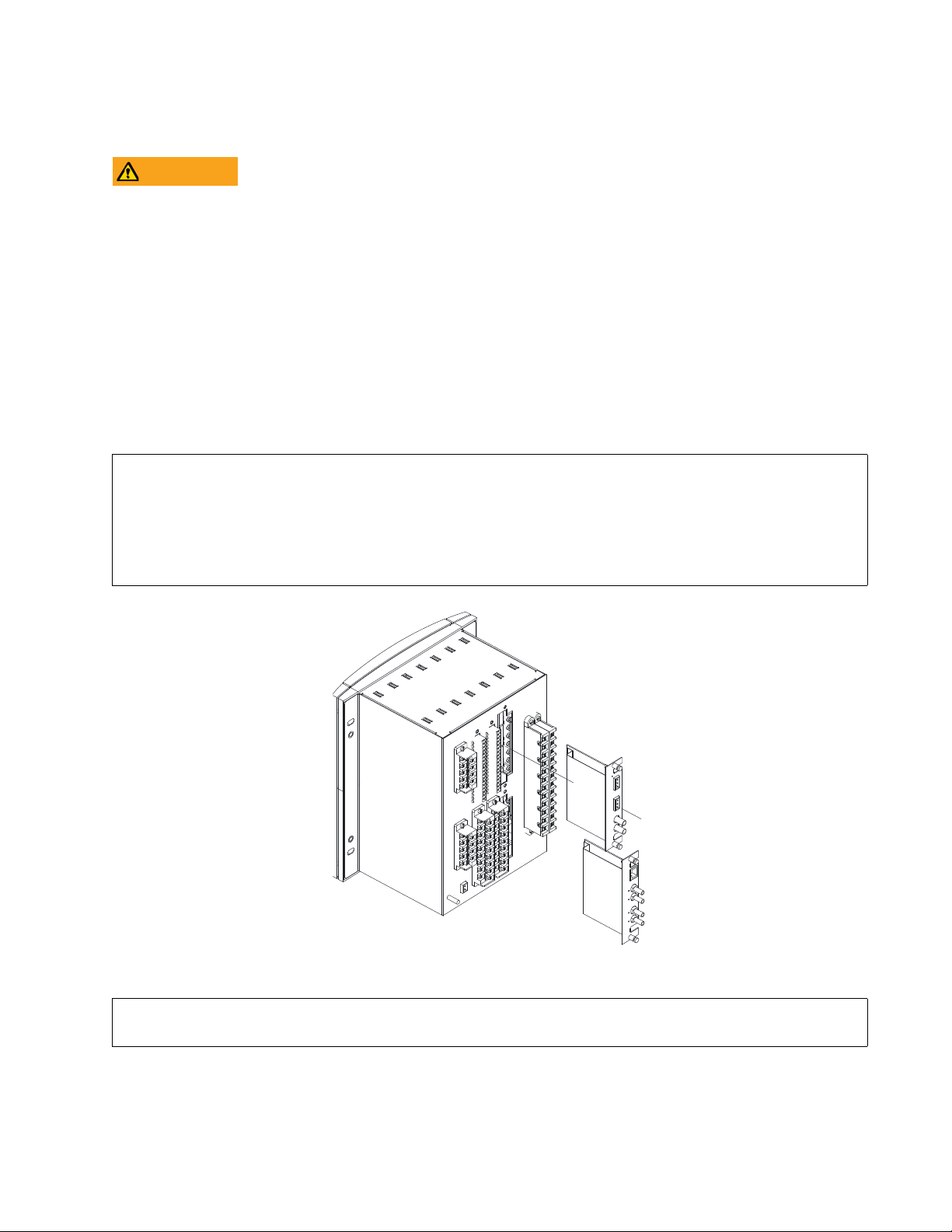
1.1.1.2 Communication board withdrawal/insertion
MODULE WITHDRAWAL AND INSERTION SHALL ONLY BE PERFORMED BY DULY QUALIFIED
SERVICE PERSONNEL. FOR PERSONAL SECURITY PURPOSES, BEFORE ACCOMPLISHING ANY
WITHDRAWAL OR INSERTION OPERATION, THE RELAY MUST BE POWERED OFF AND ALL THE REAR
TERMINALS MUST BE POTENTIAL FREE. THE RELAY MUST BE GROUNDED USING THE REAR
GROUNDING SCREW.
The modular design of the relay allows for the withdrawal and insertion of the communication module.
Figure 1-1: Module withdrawal/insertion shows the location of communication modules on the rear part of the relay.
Qualified personnel must carry out the insertion or extraction of the communication boards only after disconnecting the
relay auxiliary voltage and ensuring that all the rear terminals are potential free.
Communication boards are installed on the rear of the unit, with upper port reserved for the asynchronous
communications board and CAN bus, and the lower port for the ETHERNET board. (The Ethernet module can be withdrawn
or inserted only in models with Rear Ethernet Communication Board 2: "B", "C", "D" or "E". For the remaining options,
Ethernet communications are included in the main CPU).
Before performing any of these actions, control power must be removed from the relay and all the rear terminals must
be potential free. A grounded antistatic wristband must be used when manipulating the module in order to avoid
electrostatic discharges that may cause damage to the electronic components.
WITHDRAWAL: Loosen the small screws that keep the faceplate in place and extract the module.
INSERTION: Insert the module and press it firmly in the case, until it is completely fixed. After this, bolt the faceplate
screws and replace the control power. Check that the relay is fully operative.
GEK-113000-AF F650 DIGITAL BAY CONTROLLER 1-3
Figure 1-1: Module withdrawal/insertion
GE Multilin will not be responsible for any damage to the relay, connected equipment or personnel whenever these
safety rules are not followed.
Page 12

1.1 IMPORTANT PROCEDURES CHAPTER 1: GETTING STARTED
1.1.1.3 Magnetic module terminals
The transformer module for the VTs and CTs is already connected to a female connector screwed to the case. The current
inputs incorporate shorting bars, so that the module can be extracted without the need to short-circuit the currents
externally. It is very important, for safety reasons, not to change or switch the terminals for CTs and VTs.
Figure 1-1: Rear view of F650 unit
GE Multilin will not be responsible for any damage of the relay, connected equipment or personnel whenever
these safety rules are not followed.
1-4 F650 DIGITAL BAY CONTROLLER GEK-113000-AF
Page 13

CHAPTER 1: GETTING STARTED 1.1 IMPORTANT PROCEDURES
1.1.2 Inspection checklist
1. Unwrap the relay and inspect the relay for physical damage.
2. View the nameplate and verify that the correct model has been or
top.
dered and delivered. The model number is at the
Figure 1-2: Identification label (A4454P6)
Please ensure that you received the following items with your relay:
• Mounting screws for fixing the relay to a cabinet
• GE EnerVista™ DVD (includes the EnerVista 650 Setup
• Wiring diagram.
• Certificate of Compliance
For product information, instruction manual updates, and the latest software updates, please visit the GE Multilin Home
Page: http://www.gegridsolutions.com/multilin
GEK-113000-AF F650 DIGITAL BAY CONTROLLER 1-5
software and manuals in PDF format)
Page 14

1.1 IMPORTANT PROCEDURES CHAPTER 1: GETTING STARTED
CAUTION
Note: If there is any physical damage detected on the relay, or any of the contents listed are missing, please contact
GE Grid Solutions, Multilin immediately:
EUROPE, MIDDLE EAST AND AFRICA:
GE Grid Solutions
Av. Pinoa, 10
48170 Zamudio, Vizcaya (SPAIN)
Tel.: (34) 94-485 88 54
Fax: (34) 94-485 88 38
E-mail: multilin.tech.euro@ge.com
AMERICA, ASIA AND AUSTRALIA:
GE Grid Solutions
650 Markland Street
Markham, Ontario
Canada L6C 0M1
North America toll-free: +1 800 547 8629
Tel.: +1 905 927 7070
Fax: +1 905 927 5098
E-mail: multilin.tech@ge.com
The information provided herein is not intended to cover all the details of the variations of the
equipment, nor does it take into account the circumstances that may be present in your
installation, operating or maintenance activities.
Should you wish to receive additional information, or for any particular problem that cannot be solved by referring to the
information contained herein, please contact General Electric, Grid Solutions.
1-6 F650 DIGITAL BAY CONTROLLER GEK-113000-AF
Page 15

CHAPTER 1: GETTING STARTED 1.1 IMPORTANT PROCEDURES
1.1.3 Safety instructions
The F650 ground screw shown in Figure 1-3: Location of grounding screw must be correctly grounded.
Figure 1-3: Location of grounding screw
Before communicating with the F650 through the front USB port, ensure that the computer's power supply is grounded.
When using a laptop, it is recommended that the power supply be disconnected. In many cases the laptop may not be
correctly grounded either due to the power supply or to the connector cables used.
GE Multilin will not be responsible for any damage to the relay or connected equipment when this basic safety rule
is not followed.
GEK-113000-AF F650 DIGITAL BAY CONTROLLER 1-7
Page 16

1.1 IMPORTANT PROCEDURES CHAPTER 1: GETTING STARTED
CAUTION
1.1.3.1 General safety instructions
• Failure to practice safe working procedures is likely to damage the equipment, cause severe injury and/or death.
• The use of appropriate safety gloves, safety glasses and pr
installation, maintenance and service of the equipment.
• All procedures must be strictly adhered to.
• Failure to observe and follow the instructi
damage to the equipment and could lead to property damage, personal injury and/or death.
• Before attempting to use the equipment, it is important that all danger and caution indicators are reviewed.
• If the equipment is used in a manner not specified by t
caution. Otherwise, the protection provided by the equipment may be impaired and can result in Impaired
operation and injury.
• Beware of potential hazards, wear personal protective e
and objects that may have been left inside the equipment.
• Caution: Hazardous voltages can caus
• Test/Installation/Service personnel must be familiar with general device t
follow standard ESD precautions to avoid personal injury or equipment damage.
• Before performing visual inspections, tests, or periodic m
or disconnect all hazardous live circuits and sources of electric power.
• Failure to shut equipment power off prior to removing the pow
voltages causing injury or death.
• All recommended equipment that should be grounded must hav
for safety purposes, protection against electromagnetic interference and proper device operation.
• Equipment grounds should be bonded together and connect
power.
• Keep all ground leads as short as possible.
• At all times, equipment ground terminal must b
• While the equipment manual may suggest several safety and
conjunction with the safety codes in force at your location.
• LED transmitters are classified as IEC 60825-1 Accessible Emission Li
considered safe to the unaided eye. Do not view directly with optical instruments.
• It is the responsibility of the user to check the equipment r
commissioning, service.
• Use a lift system with side rails/bucket to reduce a fall hazar
servicing.
• In addition to the safety precautions mentioned all ele
jurisdiction electrical code.
• Before working on CTs, they must be short circuited.
• Do not remove the voltage terminal blocks
live. The voltage inputs must be de-energized prior to any servicing.
ons provided in the equipment manual(s) could cause irreversible
e shock, burns or death.
e grounded during device operation.
or disconnect the voltage input wires when the voltage phases are
otective clothing are recommended during equipment
he manufacturer or functions abnormally, proceed with
quipment and carefully inspect the work area for tools
est practices, safety precautions and
aintenance on this device or associated circuits, isolate
er connections could expose you to dangerous
e a reliable and un-compromised grounding path
ed to the facility's main ground system for primary
reliability steps, safety precautions must be used in
mit (AEL) Class 1M. Class 1M devices are
atings and installation instructions prior to
d as opposed to other means when installing or
ctrical connections made must respect the applicable local
1-8 F650 DIGITAL BAY CONTROLLER GEK-113000-AF
Page 17
CHAPTER 1: GETTING STARTED 1.1 IMPORTANT PROCEDURES
!
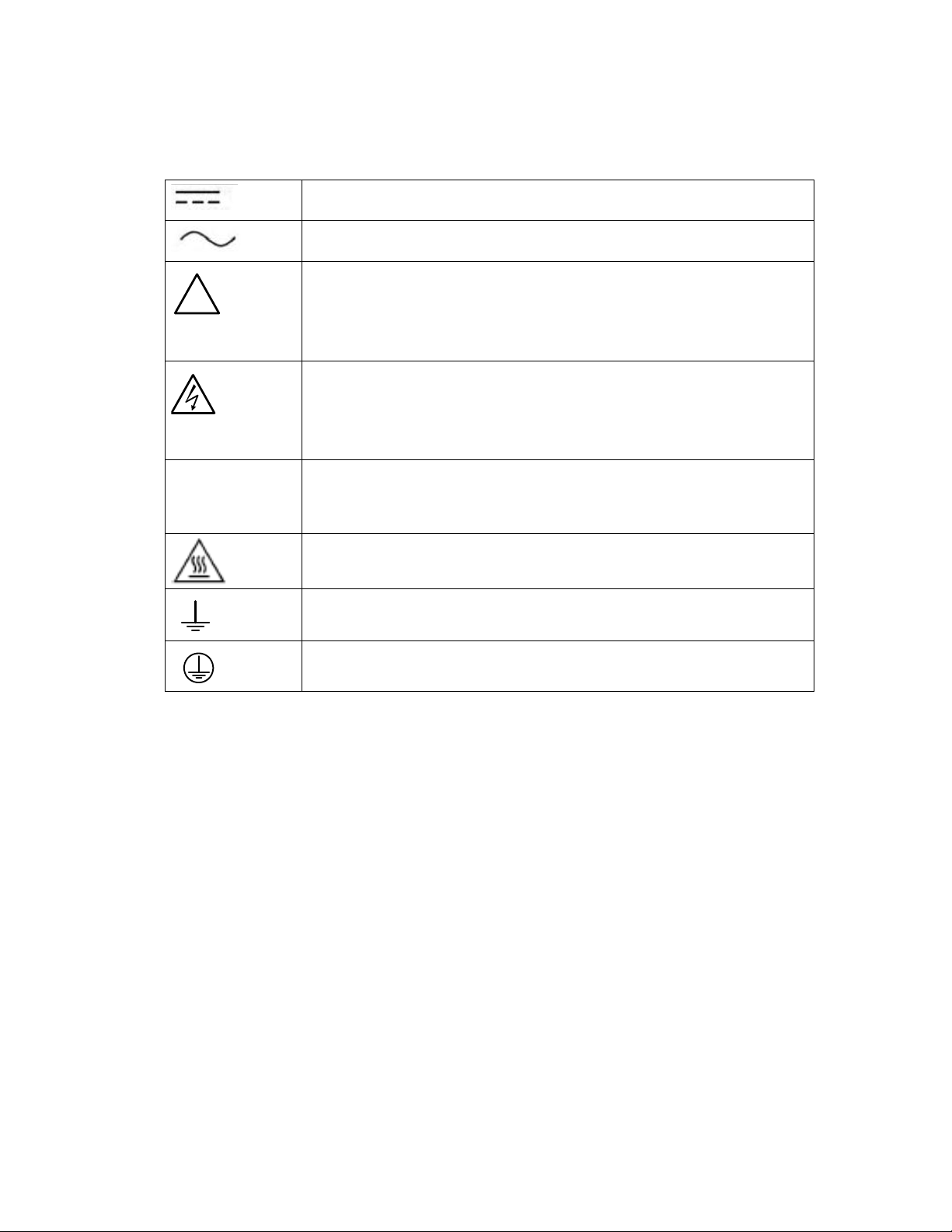
1.1.3.2 Warning symbols
The following table explains the meaning of warning symbols that may appear on the device or in this manual.
The relevant circuit is direct current .
Le circuit principal est à courant continu.
The relevant circuit is alternating current.
Le circuit principal est à courant alternatif.
CAUTION: Refer t
instructions. Failure to take or avoid a specified action can result in loss of data or
physical damage.
AVERTISSEMENT:
L'absence ou èviter de prender des mesures spècifiques peut entraîner des pertes
de données ou même causer des dommages physiques.
WARNI NG!
within the unit. Failure to take or avoid a specified action can result in physical
harm to the user.
AVERTISSEMENT! T
sont presents dans l'equipement. L'absence ou èviter de prender des mesures
spècifiques peut causer des dommages physiques à l'utilisateur.
CAUTION: Cla
DO NOT VIEW DIRECTLY WITH OPTICAL INSTRUMENTS.
AVERTISSEMENT: La
DIRECTEMENT LE DISPOSITIF QUI ÉMET LE LASER OPTIQUE.
CAUTION: Hot sur
AVERTISSEMENT: Su
o the documentation for important operating and maintenance
Se réferer à la documentation pour l'entretien et l'utilisation.
Dangerous voltage constituting a risk of electric shock is present
ensions dangereuses comportant un risque de choc électrique
ss 1M Laser (IEC 60825-1 Safety of laser products)
ser de classe 1M (IEC60825-1) ÉVITER DE REGARDER
face.
rface chaude.
Earth (Ground) Terminal.
Terminal de terre (masse).
Protective Earth Terminal.
Terminal de terre de protection.
Note: Read all instructions included in package before using your product. Additional safety information
Product Safety Supplement document available at; http://www.gegridsolutions.com/ProductSafety/
GEK-113000-AF F650 DIGITAL BAY CONTROLLER 1-9
Page 18

1.2 OVERVIEW CHAPTER 1: GETTING STARTED
1.2 Overview
1.2.1 Introduction to the 650 family of relays
The GE 650 family relay is a new generation of digital and multifunction equipment that is easily incorporated into
automation systems, at both the station and enterprise levels.
1.2.2 Hardware architecture
1.2.2.1 F650 basic design
The 650 is a digital-based device containing a central processing unit (CPU) that handles multiple types of input and output
signals. The 650 family can communicate over a local area network (LAN) with an operator interface, a programming
device, or another 650 device.
The CPU module contains firmware that provides protection elements in the form of logic algorithms, as well as
programming logic gates, timers, and latches for control features.
Input Elements accept a variety of analog or digital signals from the field. The 650 isolates and converts these signals into
logic signals used by the relay.
Output Elements convert and isolate the logic signals generated by the relay into digital signals that can be used to
control field devices.
Figure 1-1: 650 concept block diagram
1-10 F650 DIGITAL BAY CONTROLLER GEK-113000-AF
Page 19

CHAPTER 1: GETTING STARTED 1.2 OVERVIEW
1.2.2.2 F650 signal type
Contact Inputs/Outputs: Digital signals.
CT and VT inputs: Signals coming from the inputs of current and voltage transformers, used for monitoring the power
system signals.
Remote CAN Bus Inputs/Outputs: Signals associated with physical input/output contacts from a Remote Digital Input/
Output Module (CIO) connected to the 650 unit via the CAN Bus existing in options X, Y, Z, C and M for rear serial
communication board 1.
PLC: Programmable Logic Controller. Control module that enables the unit configuration (assignment of inputs/outputs)
and the implementation of logic circuits.
Protection Elements: Relay protection elements, for example: Overcurrent, overvoltage, etc.
Remote inputs and outputs: Provide a means of sharing digital point state information between remote devices using IEC
61850 GSSE and GOOSE messages.
Analog Inputs: Signals associated with transducers.
1.2.3 Communications architecture
A dedicated serial port is used for communication between the main processor and the human-machine interface. The
serial connection provides immunity against electromagnetic disturbances, thus increasing system safety.
All 650 units incorporate one RS232 (USB or DB9)serial port on the front of the relay. They can also incorporate up to two
additional communication modules on the rear.
One of the modules provides asynchronous serial communications, using different physical media (RS485 + cable remote
CAN bus I/O, plastic or glass fiber optic) depending on the selected model. The module incorporates two identical ports,
COM1 and COM2. The COM2 port is multiplexed with the front port. Additionally, this module may incorporate a port for
CAN bus communications, used for the connection to the remote CAN Bus I/O module. This feature increases the I/O
capability by up to 100% if the maximum number of I/Os available inside the relay is not enough for a specific application.
Available options are:
Table 1-1: Rear serial communications board 1
Board Code Functionality
F Without additional communication ports
A Two RS485 ports
P Two Plastic F.O. ports
G Two Glass F.O. ports
X Two RS485 ports and a CAN port for remote CAN bus Inputs/Outputs
Y Two Plastic F.O. ports and a CAN port for remote CAN bus Inputs/Outputs (fiber)
Z Two Glass F.O. ports and a CAN port for remote CAN bus Inputs/Outputs (fiber)
C CAN port for remote CAN Bus I/O (cable)
M RS485 + RS485 port and a CAN port for remote CAN Bus I/O (cable)
The other module provides Ethernet communications (ETH Port), using 10/100BaseTX (self-negotiable speed) or 100BaseFX
connectors, depending on the selected model. The most complete models include a double redundant 100BaseFX fiber
optic port. Redundancy is provided at the physical level, for options D and E; the unit incorporates internally duplicated
and independent controllers for extended system reliability and accessibility.
GEK-113000-AF F650 DIGITAL BAY CONTROLLER 1-11
Page 20

1.2 OVERVIEW CHAPTER 1: GETTING STARTED
Available Options are:
Table 1-2: REAR ETHERNET COMMUNICATIONS BOARD 2
Board Code Functionality
B One 10/100BaseTX port (self-negotiable speed)
C One 10/100BaseTX port and one 100BaseFX port.
D One 10/100BaseTX port and redundant 100BaseFX ports
E Redundant 10/100BaseTX ports
For options C and D you must select the active physical media, by means of an internal selector inside the module. The
factory configuration for this selection is the 10/100BaseTX port. For firmware versions 7.00 and above, the following
options are available:
G 1588, 10/100 Base TX* + 100 Base TX
H 1588, 10/100 Base TX* + 100 Base FX
J PRP, 1588, 10/100 Base TX* + Redundant 100 Base FX
K PRP, HSR, RSTP, 1588, 10/100 Base TX* + Redundant 100 Base FX
L PRP, 1588, 10/100 Base TX + Redundant 100 Base TX
M PRP, HSR, RSTP, 1588, 10/100 Base TX + Redundant 100 Base TX
Finally, internal communication with input and output modules is performed via an internal CAN Bus, independent of the
one used for remote CAN Bus I/Os. This provides increased communication speed, and acknowledgement of modules,
abnormalities, etc. As this is a serial port supporting a communications protocol, it provides immunity against external or
internal disturbances.
1-12 F650 DIGITAL BAY CONTROLLER GEK-113000-AF
Page 21

CHAPTER 1: GETTING STARTED 1.2 OVERVIEW
DSP
MEASUREMENT
PROCESSO R
ANALOG
INP UT S
CURENT AC
AND
VOLTAGE AC
I/O I/O
DIGITAL SUPERVISION
ETH1
ETH2 ETH3
Redundancy
(Optional)
CAN COM1 COM2
CAN
REMOTE
I/O
CAN I/O
INTE RNAL
SERIAL
COM 1
SERIAL
COM 2
SERIAL
COM H
COM2
SERIAL
COM H
HMI
HUMAN MACHINE IN TERFACE
FRONT
SERIAL
PORT
MULTIPLEXED
ETHERNET COMMUNICATIONS
MAIN PROCESSOR
COMMUNICATION
CONTROL
PROTEC TION
Figure 1-1: Communications architecture (B6816F2)
GEK-113000-AF F650 DIGITAL BAY CONTROLLER 1-13
Page 22

1.3 ENERVISTA 650 SETUP SOFTWARE CHAPTER 1: GETTING STARTED
1.3 EnerVista 650 Setup software
1.3.1 System requirements
The relay front panel or the EnerVista 650 Setup software can be used to communicate with the relay. The software
interface is the preferred method to edit settings and view actual values because the computer monitor can display more
information.
The minimum system requirements for the EnerVista 650 Setup software are as follows:
• Pentium® 4 (Core Duo recommended).
• Windows® XP with Service Pack 2 (Service Pack 3
• 1 GB of RAM (2 GB recommended).
• 500 MB free hard drive space (1 GB recommended).
• 1024 x 768 display (1280 x 800 recommended).
• RS232 and USB serial and/or Ethernet por
t for communications with the relay.
1.3.2 Installation
After ensuring the minimum requirements for using EnerVista 650 Setup are met (see previous section), obtain the
software from the GE EnerVista DVD, or download from: http://www.gegridsolutions.com/multilin/ as follows:
1. Insert the GE EnerVista DVD into the DVD drive of your computer.
2. Click In
3. When installation is complete, start the EnerVista Launchpad application.
4. Click IED
stall Now and follow the installation instructions to install the complimentary EnerVista software.
Setup in the Launch Pad window.
recommended), Windows 7, or Windows 8
Figure 1-2: Launchpad window
1-14 F650 DIGITAL BAY CONTROLLER GEK-113000-AF
Page 23

CHAPTER 1: GETTING STARTED 1.3 ENERVISTA 650 SETUP SOFTWARE
5. Click Add Product and select the “F650 Bay Controller” relay from the Install Software window as shown below. Select
the “Web” option to ensure the most recent software release, or select “CD” if you do not have a web connection, then
click Add Now to list software items for the F650.
Figure 1-3: Add Product window
6. EnerVista Launchpad obtains the installation program from the
Web or CD. Once the download is complete, double-
click the installation program to install the EnerVista 650 Setup software.
7. Follow the on-screen instructions to install the EnerVista 650 Setup software. When the Welc
click Next to continue with the installation.
Figure 1-4: EnerVista 650 Setup installation
ome window appears,
GEK-113000-AF F650 DIGITAL BAY CONTROLLER 1-15
Page 24

1.3 ENERVISTA 650 SETUP SOFTWARE CHAPTER 1: GETTING STARTED
8. When the Choose Destination Location window is displayed, change the installation directory id needed by clicking
Change… and typing in the complete path name including the new directory name. Click Next to continue with the
installation.
Figure 1-5: EnerVista 650 Setup installation cont.
9. The default program group containing the application is added to as shown in the Se
lected Program Folder window.
Click Next to begin the installation process, and all the necessary program files are copied into the selected directory.
Figure 1-6: Select program folder
1-16 F650 DIGITAL BAY CONTROLLER GEK-113000-AF
Page 25

CHAPTER 1: GETTING STARTED 1.3 ENERVISTA 650 SETUP SOFTWARE
10. To complete the installation, select the desired language for startup.
Figure 1-7: Language window
11. Click Fin
ish to end the installation. The F650 device has been added to the list of installed IEDs in the EnerVista
Launchpad window, as shown below.
Figure 1-8: EnerVista Launchpad
GEK-113000-AF F650 DIGITAL BAY CONTROLLER 1-17
Page 26

1.3 ENERVISTA 650 SETUP SOFTWARE CHAPTER 1: GETTING STARTED
1.3.3 Connecting EnerVista 650 Setup to the F650
This section is intended as a quick start guide to using the EnerVista 650 Setup software. Refer to section 4.1 in this manual
for more information about the EnerVista 650 Setup software interface.
1.3.3.1 Configuring an Ethernet connection
Before starting, verify that the Ethernet network cable is properly connected to the Ethernet port on the back of the relay.
1. Install and start the latest version of the EnerVista 650 Setup software (available from the GE EnerVista DVD or online
from http://www.gegridsolutions.com/multilin (see previous section for installation instructions).
2. Go to Co
3. Select Con
parameters that must be entered for proper Ethernet communications.
4. Enter the relay IP address (from Setpoint >
IP Address field in MODBUS TCP/IP SETUP.
5. Enter the relay ModBus address (from Setpoin
ModBus Address COM1/COM2 setting) in the Unit Identifier (Slave Address) field.
6. Enter the ModBus port address (from Setpoint > Pr
ModBus Port Number setting) in the ModBus Port field.
7. The Device has now been configured for Ethernet communications. Click ON
mmunication > Computer.
trol Type as MODBUS TCP/IP from the drop-down list. This option displays a number of interface
Product Setup > Communication Settings > Network > IP Address) in the
t > Product Setup > Communication Settings > ModBus Protocol >
oduct Setup > Communication Settings > ModBus Protocol >
to begin communicating.
1.3.3.2 Configuring the RS232 connection
Before starting, verify that the RS232 serial cable, or the USB Cable, is properly connected to the RS232port or the USB port
on the front panel of the relay.
1. Install and start the latest version of the EnerVista 650 Setup software (available from the GE EnerVista DVD or online
from http://www.gegridsolutio
2. Go to Co
3. Under Contr
4. Enter the relay Slave Address (Se
Address field. The default value is 254.
5. Enter the physical communications parameters (Baud rate and parity settings) from the Set
Communication Settings > Serial Ports menu. Default values are 19200 for baud rate and none for parity.
6. The unit has now been configured for RS232 communications. Click ON
mmunication > Computer and enter the following data referred to communications:
ol Type select No Control Type from the drop-down list.
ns.com/index.htm (see previous section for installation instructions).
tpoint > Product Setup > Communication Settings > ModBus Protocol) in the Slave
point > Product Setup >
to begin communicating.
1-18 F650 DIGITAL BAY CONTROLLER GEK-113000-AF
Page 27
CHAPTER 1: GETTING STARTED 1.4 650 HARDWARE
1.4 650 hardware
1.4.1 Mounting & wiring
Refer to Chapter 3. Hardware for detailed mounting and wiring instructions.
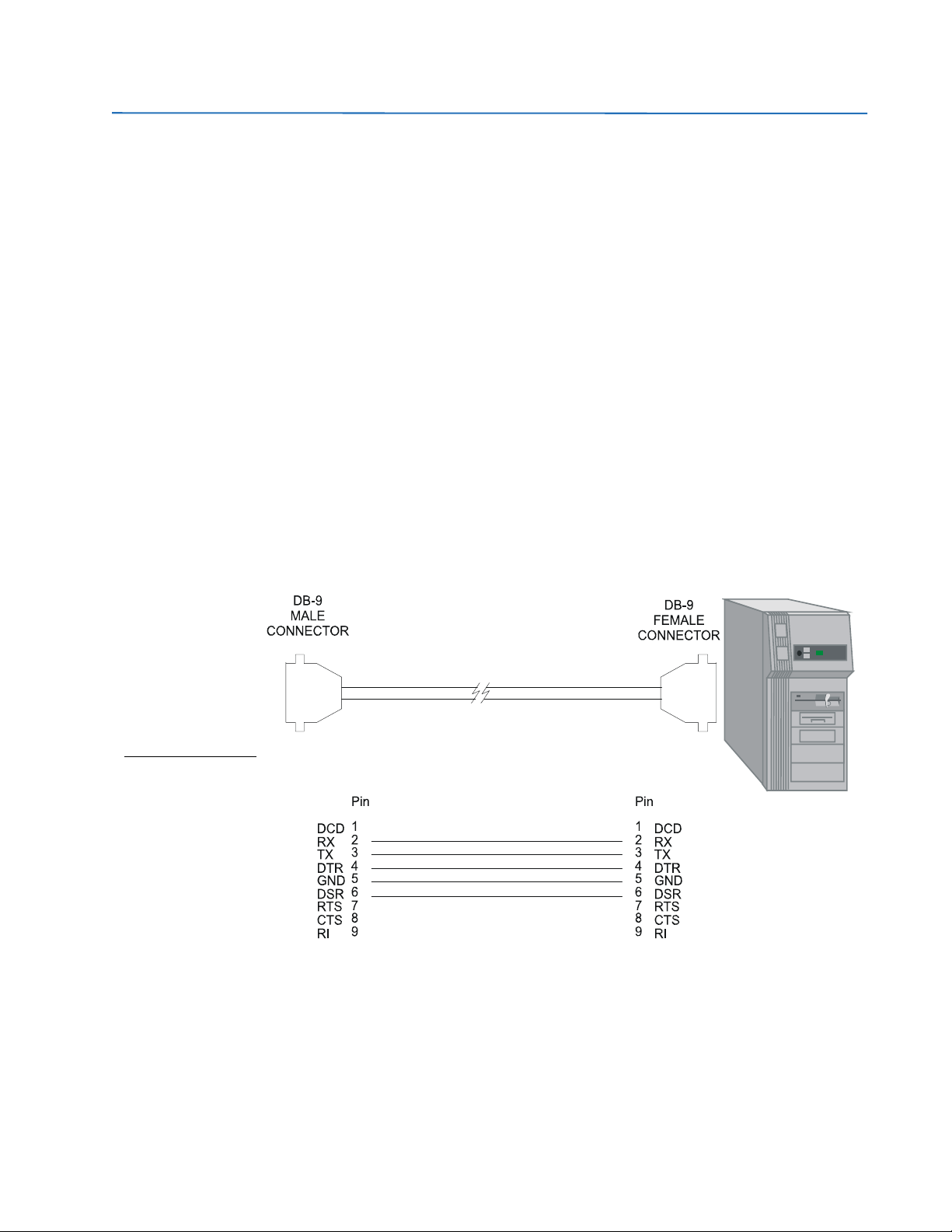
1.4.2 650 communications
The Enervista 650 Setup software communicates with the relay via the faceplate USB port in hardware 04 (E in order code)
or RS232 port or the rear RS485/Ethernet ports. To communicate via the faceplate RS232 port, a standard “straightthrough” serial cable is used. The DB-9 male end is connected to the relay and the DB-9 or DB-25 female end is connected
to the PC COM1 or COM2 port as described in Figure 1-1: Relay- PC connection for RS232 front port. To communicate via
USB port a male A / male B USB shielded wire is needed
To communicate via the F650 rear RS485 port from a PC RS232 port, the GE Multilin RS232/RS485 converter box is
required. This device (catalog number F485) connects to the computer using a “straight-through” serial cable. A shielded
twisted-pair (20, 22 or 24 AWG according to American standards; 0.25, 0.34 or 0.5 mm2 according to European standards)
connects the F485 converter to the F650 rear communication port.
To minimize communication errors that can be caused by external noise, a shielded twisted pair is recommended. In order
to avoid loops where external currents can flow, the cable shield must be grounded at one end only.
The converter box (-, +, GND) terminals are connected to the relay (SDA, SDB, GND) terminals respectively. For long
communications cables (longer than 1 km), the RS485 circuit must be terminated in an RC network (i.e. 120 ohm, 1 nF). This
circuit is shown in Figure 1-2: RS485 connection for 650 units, associated with the text Zt(*).
Figure 1-1: Relay- PC connection for RS232 front port
To minimize errors from noise, the use of shielded twisted pair wire is recommended. For correct operation, polarity must
be respected, although a different polarity will not damage the unit. For instance, the relays must be connected with all
RS485 SDA terminals connected together, and all SDB terminals connected together. This may result in confusion, as the
RS485 standard refers to terminals “A” and “B”, although many devices use terminals labeled “+” and “-“.
GEK-113000-AF F650 DIGITAL BAY CONTROLLER 1-19
Page 28

1.4 650 HARDWARE CHAPTER 1: GETTING STARTED
As a general rule, terminals labeled “A” should be connected to terminals “-“, and terminals “B” to “+”. The GND terminal
should be connected to the common wire inside the shield, when provided. Otherwise, it should be connected to the shield.
Each relay should also be daisy chained to the next relay in the system. A maximum of 32 relays can be connected in this
manner without exceeding driver capability; for larger systems, additional serial channels must be added. It is also
possible to use commercially available repeaters to increase the number of relays on a single channel. Do not use other
connection configurations.
Lightening strikes and ground surge currents can cause large momentary voltage differences between remote ends of the
communication link. For this reason, surge protection devices are provided internally. To ensure maximum reliability, all
equipment should have similar transient protection devices installed.
Figure 1-2: RS485 connection for 650 units
To communicate through the F650 rear Ethernet port from a PC, a crossover cable is required. If the connection is
performed through a hub or a switch, a direct Ethernet cable is required.
1.4.3 Faceplate display
All messages are displayed on a 20x4 character LCD display. An optional graphic display is also available. Messages are
displayed in different languages depending on the model and configuration settings.
1-20 F650 DIGITAL BAY CONTROLLER GEK-113000-AF
Page 29

CHAPTER 1: GETTING STARTED 1.4 650 HARDWARE
NOTICE
NOTICE
1.4.4 Maintenance
1.4.4.1 General maintenance
The F650 requires minimum maintenance once it is commissioned into service. F650 is a microprocessor based relay and
its characteristics do not change over time; as such no further functional tests are required. While the F650 performs
continual self-tests, it is recommended that maintenance be scheduled with other system maintenance. This maintenance
can involve in-service, out-of-service, or unscheduled maintenance.
If it is concluded that the relay or one of its modules is of concern, contact GE Multilin or one of its representative for
prompt service.
1.4.4.2 In-service maintenance
1. Visual verification of the analog value integrity such as voltage and current (in comparison to other devices in the
system).
2. Visual verification of active alarms, relay display messages and LED indications.
3. Visual inspection for any damage, corrosion, dust or loose wires.
4. Event recorder file download with further event analysis.
1.4.4.3 Out-of-service maintenance
1. Check wiring connections for firmness.
2. Analog value (current, voltages, analog inputs) injection test and metering accuracy verification. Calibrated test
uipment is required.
eq
3. Protection element setpoint verification (analog values injec
relay settings).
4. Contact inputs and outputs verification. This test can be conducted by direct change of state forcing or as part of the
syst
em functional testing.
5. Visual inspection for any damage, corrosion or dust.
6. Event recorder file download with further events analysis.
To avoid deterioration of electrolytic capacitors, power up units that are stored in a de-energized
state once per year, for one hour continuously.
tion or visual verification of setting file entries against
1.4.4.4 Unscheduled maintenance
Unscheduled maintenance such as during a disturbance causing system interruption:
• View the event recorder and oscillography or fault report for correct operation of inputs,outputs and elements.
1.4.5 Storage
Store the unit indoors in a cool, dry place. If possible, store in the original packaging. Follow the storage temperature range
outlined in the Specifications.
To avoid deterioration of electrolytic capacitors, power up units that are stored in a de-energized
state once per year, for one hour continuously.
GEK-113000-AF F650 DIGITAL BAY CONTROLLER 1-21
Page 30

1.4 650 HARDWARE CHAPTER 1: GETTING STARTED
1.4.6 Repairs
The firmware and software can be upgraded without return of the device to the factory.
For issues not solved by troubleshooting, the process to return the device to the factory for repair is as follows:
• Contact a GE Grid Solutions Technical Support Center. Contact information is found in the first chapter.
• Obtain a Return Materials Authorization (RMA) number from the Technical Support Center.
• Verify that the RMA and Commercial Invoice received have the correct information.
• Tightly pack the unit in a box with bubble wrap, foam material, or styrofoam inserts or packaging peanuts to cushion
em(s). You may also use double boxing whereby you place the box in a larger box that contains at least 5 cm of
the it
cushioning material.
• Ship the unit by courier or freight forwarder, along with the Commercial Invoice and RMA, to the factory.
• Fax a copy of the shipping information to the GE Grid Solutions service department. Customers are responsible for
shipp
ing costs to the factory, regardless of whether the unit is under warranty.
Use the detailed return procedure outlined at
https://www.gegridsolutions.com/multilin/support/ret_proc.htm
The current warranty and return information are outlined at
https://www.gegridsolutions.com/multilin/warranty.htm
1.4.7 Disposal
The F650 is intended to be part of defective large-scale stationary industrial tools and large-scale fixed installations. This
product cannot be disposed of as unsorted municipal waste in the European Union. For proper recycling return this
product to your supplier or a designated collection point. For more information go to www.recyclethis.info.
1-22 F650 DIGITAL BAY CONTROLLER GEK-113000-AF
Page 31

GE
Grid Solutions
F650 Digital Bay Controller
Chapter 2: Product Description
PRODUCT DESCRIPTION
2.1 F650 Overview
F650 is a protection, control, monitoring, metering and registering unit, suitable for many different applications, such as
main protection for distribution feeders and transmission lines, as well as backup protection for transformers, busbars,
capacitor banks, etc.
Overvoltage and undervoltage protection, overfrequency and underfrequency protection, breaker failure protection,
directional current supervision fault diagnostics and programmable logic functions are provided.
This relay also provides phase, neutral, ground and sensitive ground, instantaneous and time overcurrent protection. The
time overcurrent function provides multiple curve shapes or FlexCurves™ for optimum co-ordination. Automatic reclosing,
synchrocheck, and line fault locator features are also provided.
Voltage, current, power, and energy metering is built into the relay as a standard feature. Current parameters are
available as true RMS magnitude, or as RMS magnitude of undamental frequency and angle (phasor).
Diagnostic features include a sequence of records. The internal clock used for time-tagging can be synchronized with an
IRIG-B signal or via SNTP, DNP or Modbus protocol over the Ethernet port. From firmware version 7.00 and above, IEEE
1588 time protocol is also available. Precise time stamping allows the sequence of events to be determined throughout the
system. Oscillography data capture may be set to record the measured parameters before and after the event for viewing
on a personal computer (PC). These tools significantly reduce troubleshooting time and simplify report generation in the
event of a system fault.
A faceplate RS232 or USB port may be used to connect to a PC for programming settings and monitoring actual values.
A variety of communications modules are available. Two rear RS485 ports allow independent access by operating and
engineering personnel. All serial ports use the Modbus® RTU protocol. Optional communications modules include a
100BaseFX Ethernet interface which can be used to provide fast, reliable communications in noisy environments.
GEK-113000-AF F650 DIGITAL BAY CONTROLLER 2-1
Page 32

2.1 F650 OVERVIEW CHAPTER 2: PRODUCT DESCRIPTION
Another option provides two 100BaseFX fiber optic ports for redundancy. The Ethernet port supports IEC 61850, Modbus®/
TCP, DNP 3.0 and TFTP protocols, and allows access to the relay via any standard web browser. The IEC 60870-5-104
protocol is supported on the Ethernet port. The Ethernet port also supports the Parallel Redundancy Protocol (PRP) and
High-availability Seamless Redundancy (HSR) of IEC 62439-3 (clause 4 (PRP) and clause 5 (HSR)) for firmware version 7.00
and so on.
Rear port COM1 can be set to support IEC60870-5-103 protocol
The F650 IEDs use flash memory technology which allows field upgrading as new features are added:
Figure 2-1: FUNCTIONAL BLOCK DIAGRAM
2-2 F650 DIGITAL BAY CONTROLLER GEK-113000-AF
Page 33

CHAPTER 2: PRODUCT DESCRIPTION 2.2 ANSI DEVICE NUMBERS AND FUNCTIONS
2.2 ANSI device numbers and functions
Main features available in the relay are gathered in tables below
DEVICE NUMBER PROTECTION & CONTROL FUNCTIONS
25 Synchronism Check
27/27X Bus/Line Undervoltage
32 Sensitive Directional Power
32FP Forward Power
32N Wattmetric Zero-Sequence Directional
46 Negative Sequence Time Overcurrent
47 Negative Sequence Voltage
48 Locked Rotor
49 Thermal Image - overload protection
50 BF Breaker Failure
50PH/PL Phase Instantaneous Overcurrent (High/Low)
50N Neutral Instantaneous Overcurrent
50G Ground Instantaneous Overcurrent
50SG Ground Instantaneous Overcurrent for sensitive ground systems (measured from 5
50IG Isolated Ground Instantaneous Overcurrent (measured from 5
51N Neutral Time Overcurrent
51G Ground Time Overcurrent
51SG Sensitive Ground Time Overcurrent
51PH/V Voltage Restraint Phase Time Overcurrent
51PL/V Voltage Restraint Phase Time Overcurrent
59/59X Bus/Line Overvoltage
59NH/NL Neutral Overvoltage - High/Low
67P Phase Directional Overcurrent
67N Neutral Directional Overcurrent
67SG Sensitive Ground Directional Overcurrent
79 Autoreclose (Four shot recloser)
81 U/O Under/Over Frequency Broken Conductor Detection
N/A Load Encroachment
N/A Broken Conductor
81df/dt Frequency Rate of Change
VTFF VT Fuse Failure Detection
60CTS Failure Current Transformer Failure **
2nd Harmonic
Inhibit
transformer input)
th current transformer input)
Second Harminic Inhibit **
th current
** These functions are available for firmware version 7.50 or above
GEK-113000-AF F650 DIGITAL BAY CONTROLLER 2-3
Page 34

2.3 OTHER DEVICE FUNCTIONS CHAPTER 2: PRODUCT DESCRIPTION
2.3 Other device functions
INPUTS/OUTPUTS METERING COMMUNICATIONS
9 Analog Inputs:
5 current inputs (3 for phases, 1 for ground, 1
for sensitiv
4 voltage inputs (3 for phases, 1 for busbar or
auxil
Digital Programmable Contact Inputs (up to
64)
Digital Programmable Contact Outputs (up to
16)
32 Latched Virtual Inputs
32 Self-Reset Virtual Inputs
Virtual Outputs (up to 512) Frequency ModBus User Map
Tripping and closing circuit supervision Sequence components of currents and
Remote Inputs/Outputs (GSSE and GOOSE
messag
Analog Inputs (dCmA) Analog Comparators
e ground),
iary voltage)
es)
Metering Current for phases, ground and
ensitive ground inputs
s
Voltages phase to phase and phase to
ound
gr
Real, Reactive and Apparent Power and
wer Factor
Po
Three Phase Energy IEC 870-5-104
oltages
v
Pulse Counters IEC 870-5-103 protocol
*Digital Counters
Front RS232 port, USB port in HMI
option E, Two rear RS485/fibre optic
ports, 10/100 TX and 100 FX Mbps
Ethernet port
ModBus Communications RTU and
over TCP/IP
DNP Multimaster (3.0 Level 2)
IEC 61850 protocol
*This functionality is available from firmware version 7.00
USER INTERFACE RECORDS OTHERS
Alphanumerical display (4x20) Data Logger
Graphic display (16 x 40) Demand Breaker Control
User Programmable LEDs (15) Event Recorder (up to 128 configurable
User Programmable Keys (up to 5) Fault Locator and Fault report (up to 10
Easy menu management Oscillography (up to 20 records) Operations (up to 24)
Configurable One-Line Diagram (Graphic
mod
el only)
Phasor Diagram (available in EnerVista 650
Setup)
ev
ents)
cords)
re
Snapshot Events (up to 1023)** Web Server Application
Breaking Arcing Current (I
IRIG-B synchronization/SNTP/
IEEE 1588
Logic Equations (PLC Editor)
** Maximum number of events can vary depend on firmware version. See details in section 2.5.3.3
2
t)
2-4 F650 DIGITAL BAY CONTROLLER GEK-113000-AF
Page 35

CHAPTER 2: PRODUCT DESCRIPTION 2.4 ORDER CODES
2.4 Order codes
F650 units are supplied as ½ 19” rack, 6 units high, containing the following modules: power supply, CPU, I/O modules,
communication modules. The required information to completely define an F650 model is shown on Table 2–1:
Table 2-1: Order codes
F650 - - - F - G - - - - - DESCRIPTION
B Basic Display (See Note 2)
M Graphic Display with Standard Symbols (See Note 2)
N Graphic Display with IEC symbols (See Note 2)
REAR SERIAL COMMUNICATIONS BOARD 1
F None
A Redundant RS485
P Redundant plastic fiber optic
G Redundant glass fiber optic
X Redundant RS485 + fiber remote CAN bus I/O
Y Redundant plastic fiber optic + fiber remote CAN bus I/O
Z Redundant glass fiber optic + fiber remote CAN bus I/O
C Cable Remote CAN bus I/O
M RS485 + cable Remote CAN bus I/O
REAR ETHERNET COMMUNICATIONS BOARD 2
B 10/100 Base TX
C 10/100 Base TX + 100 Base FX
D 10/100 Base TX + Redundant 100 Base FX
E Redundant 10/100 Base TX
G 1588, 10/100 Base TX* + 100 Base TX (See Note 3)
H 1588, 10/100 Base TX* + 100 Base FX (See Note 3)
J PRP, 1588, 10/100 Base TX* + Redundant 100 Base FX (See Note 4)
K PRP, HSR, RSTP, 1588, 10/100 Base TX* + Redundant 100 Base FX
L PRP, 1588, 10/100 Base TX*+ Redundant 100 Base TX (See Note 4)
M PRP, HSR, RSTP, 1588, 10/100 Base TX*+ Redundant 100 Base TX
1 16 Digital Inputs + 8 Outputs
2 8 Digital Inputs + 8 Outputs + 2 trip/close circuit supervision circuits
4 32 Digital Inputs
5 16 Digital Inputs + 8 Analog Inputs
0 None
1 16 Digital Inputs + 8 Outputs
4 32 Digital Inputs (see Note 1)
5 16 Digital Inputs + 8 Analog Inputs (See Note 1)
LO 24-48 Vdc (range 19.2 – 57.6)
HI
LOR Redundant LO
HIR Redundant HI
- English/English
C Chinese/English (See Note 2and Note 7)
(See not
e4)
(See Not
e 4)
I/O BOARD IN SLOT F
I/O BOARD IN SLOT G
AUXILIARY VOLTAGE
110-250 Vdc (range 88 – 300).
120-230 Vac (range 96 – 250)
LANGUAGE
GEK-113000-AF F650 DIGITAL BAY CONTROLLER 2-5
Page 36

2.4 ORDER CODES CHAPTER 2: PRODUCT DESCRIPTION
F French/English
P Russian/English (See Note 2)
S Spanish/English
T Turkish/English
COMMUNICATION PROTOCOL
- Modbus® RTU, TCP/IP, DNP 3.0 Level 2, IEC 60870-5-104
3 IEC 60870-5-103, Modbus® RTU,TCP/IP
6
IEC 61850 (See Note 10), Modbus® RTU and TCP/IP,DNP 3.0 Level 2,
IEC 60870-5-104
ENVIRONMENTAL PROTECTION
- Without Harsh (Chemical) Environment Conformal Coating
H Harsh (Chemical) Environment Conformal Coating
M Marine range: Lloyd’s Register (See Note 9)
ENHANCED DISPLAY
- Display with RS232 (See Note 8)
E Enhanced Display with USB
SPECIAL MODELS MOD001 (Abbreviation "+M1"): have 6A output contacts instead of 16A.
Notes:
(*) For firmware version 7.00 or above, Port
E is intended for maintenance purposes.
(1) The digit selected for option G must be equal or higher than the d
only.
F1G5 is a valid selection and F5G1 is an invalid selection.
(2) Display options with language selection:
Graphic display: available for English, French, Spanish and Chinese languages. For Chinese and Russian only IEC symbols option is
available (N in order code).
Basic display: available for all languages
(3) Advance functionalities Level I:
G, H: IEEE1588 Precision Time Protocol (PTP), 61850 Edition 2.0. Digital counters. Max numbers of starts and Cold Load Pick-up
functionalities.
(4) Advance functionalities Level II:
J, L: Parallel Redundancy Port (PRP,) IEEE1588 Precision Time Protocol (PTP), 61850 Edition 2.0. Digital counters, DFT, 16 Switchgear
mapped in IEC61850, 16 nodes CILO, mapping of BlkOpn and BlkCls leafs of XSWI nodes, Max numbers of starts and Cold Load Pickup functionalities.
K, M: High-Availability Seamless Redundancy (HSR), Rapid Spanning Tree Protocol (RSTP), Parallel Redundancy Port (PRP,) IEEE1588
Precision Time Protocol (PTC), 61850 Edition 2.0. Digital counters, DFT, 16 Switchgear mapped in IEC61850, 16 nodes CILO, mapping of
BlkOpn and BlkCls leafs of XSWI nodes, Max numbers of starts and Cold Load Pick-up functionalities.
(5) For special models requested, relay order code shall be codified as a standard model (Table 2-1) following by Abbreviation + MX where X
indicates the number of special model selected.
(6) For non-last released firmware version models requested, relay order code shall be codified as standard model (Table 2-1), following
by Abbreviation +VXXXXXBYYYYY where XXXXX is the firmware version requested and YYYYY is the corresponding bootcode version.
(7) Chinese Language: This language is not supported for Rear Ethernet Communication Board options: G, H, J,K,L or M
(8) Display option with RS232 is not available for F650 Models with Rear Ethernet Communication Board 2 options from G to M or with
Environmental Protection option M
(9) Marine Range option M in the Environmental Protection section is only available with REAR ETHERNET COMMUNICATIONS BOARD 2
options G,H,J,K,L or M
(10) For F650 whose order code has Communication Option "6", Rear Ethernet Communication Board 2 and that contains firmware version
7.52, IEC 61850 Edition 1.0 is also available in relays with this option selected. Relay will work with IEC 61850 Edition 1.0 or Edition 2.0
depend on which ICD have been sent to the device. See section
igit selected for option F for models including boards 4 and 5
2-6 F650 DIGITAL BAY CONTROLLER GEK-113000-AF
Page 37

CHAPTER 2: PRODUCT DESCRIPTION 2.4 ORDER CODES
2.4.1 CIO Modules
For applications requiring a high number of inputs and outputs, F650 units can be connected to a CIO module
(Remote CAN bus I/O module) for using up to 2 additional boards.
F650 units allow monitoring and configuring these I/O boards as if they were internal boards, located on slots F and G. In
this case, slots are labeled as H and J.
The required information to completely define a CIO Module is shown on Table 2–2:.
Table 2-2: Order code for CIO module
CIO H - J - - DESCRIPTION
I/O BOARD IN SLOT H
1 16 Digital inputs + 8 outputs
2 8 Digital Inputs + 8 Outputs + 2 trip/close circuit supervision circuits
4 32 Digital Inputs
5 16 Digital Inputs + 8 Analog Inputs
I/O BOARD IN SLOT J
0 None
1 16 Digital inputs + 8 outputs
4 32 Digital Inputs (See Note 1)
5 16 Digital Inputs + 8 Analog Inputs (See Note 1)
AUXILIARY VOLTAGE
LO 24-48 Vdc (range 19.2 – 57.6)
HI 110-250 Vdc (range 88 – 300)
120-230 Vac (range 96 – 250)
ENVIRONMENTAL PROTECTION
H Harsh (Chemical) Environment Conformal Coating
(1) The digit selected for option J must be equal or higher than the digit selected for option H for models including boards 4 and 5.
CIOH1J5**: is a valid selection
CIOH5J1**: is an invalid selection
GEK-113000-AF F650 DIGITAL BAY CONTROLLER 2-7
Page 38

2.5 TECHNICAL SPECIFICATIONS CHAPTER 2: PRODUCT DESCRIPTION
2.5 Technical specifications
TECHNICAL SPECIFICATIONS ARE SUBJECT TO CHANGE WITHOUT NOTICE
2.5.1 Protection
Phase and Ground protection functions use currents measured through CT inputs for performing internal calculations,
while the Neutral protection functions use the current calculated from three phase currents.
The sensitive ground protection functions are usually used for applications where the neutral is completely isolated. These
functions use current measured though the sensitive ground current input. This CT has a sensitivity 10 time higher than
standard CT inputs (Connected to 1A and 5A CT) and its current withstand is lower.
PHASE TIME OVERCURRENT (51PH/51PL)
Current Input:.............................................................................phasor (without harmonics) or RMS
Rated Current:............................................................................for connection to 1 or 5 A CTs
Pickup Level: ...............................................................................0.05 to 160.00 A in steps of 0.01 A
Dropout Level:............................................................................97% to 98% of the pickup level
Level Accuracy: .........................................................................values at nominal frequency:
±0.5% of the reading ± 10 mA from 0.05 to 10.00 A
±1.5% of the reading for higher values
Curve Shape: ..............................................................................IEEE extremely/very/moderately inverse
IEC A/B/C/long-time inverse/short time inverse curve
IAC extremely/very/moderately inverse
ANSI extremely/very/normally/moderately inverse
2
t
I
Definite time
Rectifier curve
FlexCurve
Curve Multiplier (Time Dial):.................................................0.00 to 900.00 s in steps of 0.01 s
Reset Type:..................................................................................instantaneous or time delayed, according to IEEE
Timing Accuracy: .....................................................................Operate at > 1.03 times the pickup ±3% of operate time or 50 ms
(whichever is greater)
Voltage Restraint:.....................................................................selectable by setting
Saturation Level:.......................................................................48 times the pickup level
Snapshot Events:......................................................................selectable by setting
TM
A/B/C/D user curve
2-8 F650 DIGITAL BAY CONTROLLER GEK-113000-AF
Page 39

CHAPTER 2: PRODUCT DESCRIPTION 2.5 TECHNICAL SPECIFICATIONS
GROUND TIME OVERCURRENT (51G)
Current Input:............................................................................. phasor (without harmonics) or RMS
Rated Current:........................................................................... for connection to 1 or 5 A CTs
Pickup Level:............................................................................... 0.05 to 160.00 A in steps of 0.01 A
Dropout Level:........................................................................... 97% to 98% of the pickup level
Level Accuracy: ........................................................................ values at nominal frequency:
±0.5% of the reading ± 10 mA from 0.05 to 10.00 A
±1.5% of the reading for higher values
Curve Shape:.............................................................................. IEEE extremely/very/moderately inverse
IEC A/B/C/long-time inverse/short time inverse curve
IAC extremely/very/moderately inverse
ANSI extremely/very/normally/moderately inverse
2
t
I
Definite time
Rectifier curve
FlexCurve
Curve Multiplier (Time Dial): ................................................ 0.00 to 900.00 s in steps of 0.01 s
Reset Type: .................................................................................instantaneous or time delayed, according to IEEE
Timing Accuracy:..................................................................... Operate at > 1.03 times the pickup ±3% of operate time or 50 ms
(whichever is greater)
Saturation Level: ......................................................................48 times the pickup level
Snapshot Events: ..................................................................... selectable by setting
TM
A/B/C/D user curve
NEUTRAL TIME OVERCURRENT (51N)
Current Input:............................................................................. fundamental phasor (without harmonics) or RMS
Pickup Level:............................................................................... 0.05 to 160.00 A in steps of 0.01 A
Dropout Level:........................................................................... 97% to 98% of the pickup level
Level Accuracy: ........................................................................ values at nominal frequency:
±0.5% of the reading ± 10 mA from 0.05 to 10.00 A
±1.5% of the reading for higher values
Curve Shape:.............................................................................. IEEE extremely/very/moderately inverse
IEC A/B/C/long-time inverse/short time inverse curve
IAC extremely/very/moderately inverse
ANSI extremely/very/normally/moderately inverse
2
t
I
Definite time
Rectifier curve
FlexCurve
Curve Multiplier (Time Dial): ................................................ 0.00 to 900.00 s in steps of 0.01 s
Reset Type: .................................................................................instantaneous or time delayed, according to IEEE
Timing Accuracy:..................................................................... Operate at > 1.03 times the pickup ±3% of operate time or 50 ms
(whichever is greater)
Saturation Level: ......................................................................48 times the pickup level
Snapshot Events: ..................................................................... selectable by setting
TM
A/B/C/D user curve
GEK-113000-AF F650 DIGITAL BAY CONTROLLER 2-9
Page 40

2.5 TECHNICAL SPECIFICATIONS CHAPTER 2: PRODUCT DESCRIPTION
SENSITIVE GROUND TIME OVERCURRENT (51SG)
Current Input:.............................................................................phasor (without harmonics) or RMS
Rated Current:............................................................................for connection to 1 or 5 A CTs
Pickup Level: ...............................................................................0.005 to 16.000 A in steps of 0.001 A
Dropout Level:............................................................................97% to 98% of the pickup level
Level Accuracy: .........................................................................values at nominal frequency:
±1.5% of the reading ± 1 mA from 0.005 to 16.000 A
Curve Shape: ..............................................................................IEEE extremely/very/moderately inverse
IEC A/B/C/long-time inverse/short time inverse curve
IAC extremely/very/moderately inverse
ANSI extremely/very/normally/moderately inverse
2
t
I
Definite time
Rectifier curve
TM
FlexCurve
A/B/C/D user curve
Curve Multiplier (Time Dial):.................................................0.00 to 900.00 s in steps of 0.01 s
Reset Type:..................................................................................instantaneous or time delayed, according to IEEE
Timing Accuracy: .....................................................................Operate at > 1.03 times the pickup ±3% of operate time or 50 ms
(whichever is greater)
Saturation Level:.......................................................................48 times the pickup level
Snapshot Events:......................................................................selectable by setting
PHASE AND GROUND INSTANTANEOUS OVERCURRENT (50PH/50PL/50G)
Current Input:.............................................................................phasor (without harmonics) or RMS
Rated Current:............................................................................for connection to 1 or 5 A CTs
Pickup Level: ...............................................................................0.05 to 160.00 A in steps of 0.01 A
Dropout Level:............................................................................97% to 98% of the pickup level
Level Accuracy: .........................................................................values at nominal frequency:
±0.5% of the reading ± 10 mA from 0.05 to 10.00 A
±1.5% of the reading for higher values
Overreach: ...................................................................................< 2%
Trip Delay:....................................................................................0.00 to 900.00 s in steps of 0.01 s
Reset Delay:................................................................................0.00 to 900.00 s in steps of 0.01 s
Operate Time: ............................................................................< 50 ms at 3 x pickup at 50 Hz, typically
Timing Accuracy: .....................................................................at 0 ms time delay (no intentional delay): 50 ms
at non-zero time delay: ±3% of operate time or 50 ms
(whichever is greater)
Snapshot Events:......................................................................selectable by setting
NEUTRAL INSTANTANEOUS OVERCURRENT (50N)
Current Input:.............................................................................fundamental phasor (without harmonics)
Pickup Level: ...............................................................................0.05 to 160.00 A in steps of 0.01 A
Dropout Level:............................................................................97% to 98% of the pickup level
Level Accuracy: .........................................................................values at nominal frequency:
±0.5% of the reading ± 10 mA from 0.05 to 10.00 A
±1.5% of the reading for higher values
Overreach: ...................................................................................< 2%
Trip Delay:....................................................................................0.00 to 900.00 s in steps of 0.01 s
Reset Delay:................................................................................0.00 to 900.00 s in steps of 0.01 s
Operate Time: ............................................................................< 50 ms at 3 x pickup at 50 Hz, typically
Timing Accuracy: .....................................................................at 0 ms time delay (no intentional delay): 50 ms
at non-zero time delay: ±3% of operate time or 50 ms
(whichever is greater)
Snapshot Events:......................................................................selectable by setting
2-10 F650 DIGITAL BAY CONTROLLER GEK-113000-AF
Page 41

CHAPTER 2: PRODUCT DESCRIPTION 2.5 TECHNICAL SPECIFICATIONS
SENSITIVE GROUND INSTANTANEOUS OVERCURRENT (50SG)
Current Input:............................................................................. phasor (without harmonics) or RMS
Rated Current:........................................................................... for connection to 1 or 5 A CTs
Pickup Level:............................................................................... 0.005 to 16.000 A in steps of 0.001 A
Level Accuracy: ........................................................................ values at nominal frequency:
±1.5% of the reading ± 1 mA from 0.005 to 16.000 A
Overreach: .................................................................................. < 2%
Trip Delay: ................................................................................... 0.00 to 900.00 s in steps of 0.01 s
Reset Delay: ............................................................................... 0.00 to 900.00 s in steps of 0.01 s
Operate Time:............................................................................ < 50 ms at 3 x pickup at 50 Hz, typically
Timing Accuracy:..................................................................... at 0 ms time delay (no intentional delay): 50 ms
at non-zero time delay: ±3% of operate time or 50 ms
(whichever is greater)
Snapshot Events: ..................................................................... selectable by setting
ISOLATED GROUND INSTANTANEOUS OVERCURRENT (50IG)
Current Input:............................................................................. fundamental phasor (without harmonics)
Voltage Input: ............................................................................fundamental phasor (without harmonics)
Current Pickup Level:.............................................................. 0.005 to 0.400 A in steps of 0.001 A
Voltage Pickup Level: ............................................................. 2 to 70 V in steps of 1 V
Dropout Level:........................................................................... 97% to 98% of the pickup level
Level Accuracy: ........................................................................ ±1.5% of the reading ± 1 mA from 0.005 to 16.000 A
Trip Delay: ................................................................................... 0.00 to 900.00 s in steps of 0.01 s
Time to Instantaneous:......................................................... 0.00 to 900.00 s in steps of 0.01 s
Operate Time:............................................................................ < 50 ms at 3 x pickup at 50 Hz, typically
Timing Accuracy:..................................................................... at 0 ms time delay (no intentional delay): 50 ms
at non-zero time delay: ±3% of operate time or 50 ms
(whichever is greater)
Snapshot Events: ..................................................................... selectable by setting
NEGATIVE SEQUENCE CURRENT (46)
Current Input:............................................................................. fundamental phasor (without harmonics)
Pickup Level:............................................................................... 0.05 to 160.00 A in steps of 0.01 A
Dropout Level:........................................................................... 97% to 98% of the pickup level
Level Accuracy: ........................................................................ values at nominal frequency:
±0.5% of the reading ±10 mA from 0.05 to 10.00 A
±1.5% of the reading for higher values
Curve Shape:.............................................................................. IEEE extremely/very/moderately inverse
IEC A/B/C/long-time inverse/short time inverse curve
IAC extremely/very/moderately inverse
ANSI extremely/very/normally/moderately inverse
2
t
I
Definite time
Rectifier curve
FlexCurve
Curve Multiplier (Time Dial): ................................................ 0.00 to 900.00 s in steps of 0.01 s
Reset Type: .................................................................................instantaneous or time delayed, according to IEEE
Timing Accuracy:..................................................................... Operate at > 1.03 times the pickup ±3% of operate time or 50 ms
(whichever is greater)
Saturation Level: ......................................................................48 times the pickup level
Snapshot Events: ..................................................................... selectable by setting
TM
A/B/C/D user curve
GEK-113000-AF F650 DIGITAL BAY CONTROLLER 2-11
Page 42

2.5 TECHNICAL SPECIFICATIONS CHAPTER 2: PRODUCT DESCRIPTION
PHASE DIRECTIONAL (67P)
Directionality:.............................................................................forward and reverse selectable by setting
Polarizing:.....................................................................................quadrature voltage:
ABC seq: Phase A (VBC), Phase B (VCA), Phase C (VAB)
ACB seq: Phase A (VCB), Phase B (VAC), Phase C (VBA)
Polarizing Voltage Threshold:..............................................0 to 300 Vac in steps of 1 V
Current Sensitivity Threshold:.............................................50 mA
Characteristic Angle:...............................................................-90º to +90º in steps of 1º
Block Logic: .................................................................................permission or block selectable by setting
Angle Accuracy:........................................................................±3º for I > 0.1 A and V > 5 Vac
Voltage Memory Time:...........................................................0.00 to 3.00 s in steps of 0.01 s
Operate Time: ............................................................................< 30 ms, typically
GROUND DIRECTIONAL (67G)
Directionality:.............................................................................forward and reverse selectable by setting
Polarizing:.....................................................................................voltage, current, dual
Polarizing Voltage:....................................................................V
Polarizing Current:....................................................................I
Operating Current:...................................................................I
Polarizing Voltage Threshold:..............................................0 to 300 Vac in steps of 1 V
Polarizing Current Threshold:..............................................0.005 A
Characteristic Angle:...............................................................-90º to +90º in steps of 1º
Block Logic: .................................................................................permission or block selectable by setting
Angle Accuracy:........................................................................±3º for I > 0.1 A and V > 5 Vac
Operate Time: ............................................................................< 30 ms, typically
(measured or calculated, selected by setting)
N
(measured from 5th current transformer)
sg
(measured from 4th current transformer)
g
NEUTRAL DIRECTIONAL (67N)
Directionality:.............................................................................forward and reverse selectable by setting
Polarizing:.....................................................................................voltage, current, dual
Polarizing Voltage:....................................................................V
Polarizing Current:....................................................................I
Operating Current:...................................................................I
(measured or calculated, selected by setting)
N
(measured from 5th current transformer)
sg
N
Polarizing Voltage Threshold:..............................................0 to 300 Vac in steps of 1 V
Polarizing Current Threshold:..............................................0.005 A
Characteristic Angle:...............................................................-90º to +90º in steps of 1º
Block Logic: .................................................................................permission or block selectable by setting
Angle Accuracy:........................................................................±3º for I > 0.1 A and V > 5 Vac
Operate Time: ............................................................................< 30 ms, typically
SENSITIVE GROUND DIRECTIONAL (67SG)
Directionality:.............................................................................forward and reverse selectable by setting
Polarizing:.....................................................................................voltage
Polarizing Voltage:....................................................................V
Operating Current:...................................................................I
Polarizing Voltage Threshold:..............................................0 to 300 Vac in steps of 1 V
Characteristic Angle:...............................................................-90º to +90º in steps of 1º
Block Logic: .................................................................................permission or block selectable by setting
Angle Accuracy:........................................................................±2º for I > 0.1 A and V > 5 Vac
Operate Time: ............................................................................< 30 ms, typically
(measured or calculated, selected by setting)
N
(measured from 5th current transformer)
sg
2-12 F650 DIGITAL BAY CONTROLLER GEK-113000-AF
Page 43

CHAPTER 2: PRODUCT DESCRIPTION 2.5 TECHNICAL SPECIFICATIONS
THERMAL MODEL (49)
Current Input:............................................................................. fundamental phasor (without harmonics)
Rated Current:........................................................................... for connection to 1 or 5 A CTs
Pickup Level:............................................................................... 0.05 to 160.00 A in steps of 0.01 A
Dropout Level:........................................................................... 97% to 98% of the pickup level
Level Accuracy: ........................................................................ values at nominal frequency:
±0.5% of the reading ± 10 mA from 0.05 to 10.00 A
±1.5% of the reading for higher values
Timing Accuracy:..................................................................... ±3.5% of operating time or 50 ms (whichever is greater)
Heating Constant:.................................................................... 3.0 to 600.0 minutes in steps of 0.1 minutes
Cooling Constant: ....................................................................1.00 to 6.00 times the heating constant, in steps of 0.01
Snapshot Events: ..................................................................... selectable by setting
PHASE OVERVOLTAGE (59P)
Voltage Input: ............................................................................fundamental phasor (without harmonics) of phase-to-phase voltages
Pickup Level:............................................................................... 2 to 30 V in steps of 1 V
Dropout Level:........................................................................... 97% to 98% of the pickup level
Level Accuracy: ........................................................................ ±1% of the reading from 10 to 208 V at nominal frequency
Trip Delay: ................................................................................... 0.00 to 900.00 s in steps of 0.01 s
Reset Delay: ............................................................................... 0.00 to 900.00 s in steps of 0.01 s
Timing Accuracy:..................................................................... ±3.5% of operating time or 50 ms (whichever is greater)
Logic: ............................................................................................. Any/Two/All phases logic, selectable by setting
Snapshot Events: ..................................................................... selectable by setting
PHASE UNDERVOLTAGE (27P)
Voltage Input: ............................................................................fundamental phasor of phase-to-ground or phase-to-phase voltages (selectable by
setting)
Pickup Level:............................................................................... 3 to 300 V in steps of 1 V
Dropout Level:........................................................................... 102% to 103% of the pickup level
Level Accuracy: ........................................................................ ±1% of the reading from 10 to 208 V at nominal frequency
Trip Delay: ................................................................................... 0.00 to 900.00 s in steps of 0.01 s
Curve Shapes: ........................................................................... fixed time or inverse curves
Reset Type: .................................................................................instantaneous
Curve Multiplier (Time Dial): ................................................ 0.00 to 900.00 s in steps of 0.01 s
Timing Accuracy:..................................................................... ±3.5% of operating time or 50 ms (whichever is greater)
Minimum Voltage Threshold:.............................................. 0 to 300 V in steps of 1 V
Logic: ............................................................................................. Any/Two/All phases logic, selectable by setting
Supervised by Breaker:......................................................... selectable by setting
Snapshot Events: ..................................................................... selectable by setting
NEUTRAL OVERVOLTAGE (59NH/59NL)
Voltage Input: ............................................................................fundamental phasor of the neutral voltage
Pickup Level:............................................................................... 3 to 300 V in steps of 1 V
Dropout Level:........................................................................... 97% to 98% of the pickup level
Level Accuracy: ........................................................................ ±1% of the reading from 10 to 208 V at nominal frequency
Trip Delay: ................................................................................... 0.00 to 900.00 s in steps of 0.01 s
Reset Delay: ............................................................................... 0.00 to 900.00 s in steps of 0.01 s
Timing Accuracy:..................................................................... ±3.5% of operating time or 50 ms (whichever is greater)
Snapshot Events: ..................................................................... selectable by setting
GEK-113000-AF F650 DIGITAL BAY CONTROLLER 2-13
Page 44

2.5 TECHNICAL SPECIFICATIONS CHAPTER 2: PRODUCT DESCRIPTION
NEGATIVE SEQUENCE OVERVOLTAGE (47)
Voltage Input:.............................................................................fundamental phasor
Pickup Level: ...............................................................................3 to 300 V in steps of 1 V
Dropout Level:............................................................................97% to 98% of the pickup level
Level Accuracy: .........................................................................±1% of the reading from 10 to 208 V
Trip Delay:....................................................................................0.00 to 900.00 s in steps of 0.01 s
Reset Delay:................................................................................0.00 to 900.00 s in steps of 0.01 s
Timing Accuracy: .....................................................................±3.5% of operating time or 50 ms (whichever is greater)
Snapshot Events:......................................................................selectable by setting
AUXILIARY OVERVOLTAGE (59X)
Voltage Input:.............................................................................fundamental phasor of the auxiliary voltage
Pickup Level: ...............................................................................3 to 300 V in steps of 1 V
Dropout Level:............................................................................97% to 98% of the pickup level
Level Accuracy: .........................................................................±1% of the reading from 10 to 208 V at nominal frequency
Trip Delay:....................................................................................0.00 to 900.00 s in steps of 0.01 s
Reset Delay:................................................................................0.00 to 900.00 s in steps of 0.01 s
Timing Accuracy: .....................................................................±3.5% of operating time or 50 ms (whichever is greater)
Snapshot Events:......................................................................selectable by setting
AUXILIARY UNDERVOLTAGE (27X)
Voltage Input:.............................................................................fundamental phasor of the auxiliary voltage
Pickup Level: ...............................................................................3 to 300 V in steps of 1 V
Dropout Level:............................................................................102% to 103% of the pickup level
Level Accuracy: .........................................................................±1% of the reading from 10 to 208 V at nominal frequency
Curve Shapes: ............................................................................fixed time or inverse curves
Reset Type:..................................................................................instantaneous
Curve Multiplier (Time Dial):.................................................0.00 to 900.00 s in steps of 0.01 s
Timing Accuracy: .....................................................................±3.5% of operating time or 50 ms (whichever is greater)
Snapshot Events:......................................................................selectable by setting
UNDERFREQUENCY (81U)
Pickup Level: ...............................................................................20.00 to 65.00 Hz in steps of 0.01 Hz
Dropout Level:............................................................................pickup + 0.03 Hz
Level Accuracy: .........................................................................±0.05 Hz of the reading from 30 to 80 Hz
Trip Delay:....................................................................................0.00 to 900.00 s in steps of 0.01 s
Reset Delay:................................................................................0.00 to 900.00 s in steps of 0.01 s
Minimum Voltage Threshold:..............................................10 to 300 V in steps of 1 V
Time Delay Accuracy:............................................................0 to 7 cycles
Operate Time: ............................................................................typically 10 cycles at 0.1 Hz/s change
Snapshot Events:......................................................................selectable by setting
OVERFREQUENCY (81O)
Pickup Level: ...............................................................................20.00 to 65.00 Hz in steps of 0.01 Hz
Dropout Level:............................................................................pickup - 0.03 Hz
Level Accuracy: .........................................................................±0.05 Hz of the reading from 30.00 to 80.00 Hz
Trip Delay:....................................................................................0.00 to 900.00 s in steps of 0.01 s
Reset Delay:................................................................................0.00 to 900.00 s in steps of 0.01 s
Minimum Voltage Threshold:..............................................10 to 300 V in steps of 1 V
Time Delay Accuracy:............................................................0 to 7 cycles
Operate Time: ............................................................................typically 10 cycles at 0.1 Hz/s change
Snapshot Events:......................................................................selectable by setting
2-14 F650 DIGITAL BAY CONTROLLER GEK-113000-AF
Page 45

CHAPTER 2: PRODUCT DESCRIPTION 2.5 TECHNICAL SPECIFICATIONS
FORWARD POWER (32FP)
Current, Voltage: ......................................................................fundamental phasor (primary values)
Number of Stages:................................................................... 2
Pickup Level:............................................................................... 0.00 to 10000.00 MW in steps of 0.01 MW
Dropout Level:........................................................................... 97% to 98% of the pickup level
Level Accuracy for Primary Magnitudes:..................... ±3% of complete range
Trip Delay (Two Stages):........................................................ 0.00 to 900.00 s in steps of 0.01 s
Timing Accuracy:..................................................................... ±3.5% of operate time or 50 ms (whichever is greater)
Block Time After Close: .........................................................0.00 to 900.00 s in steps of 0.01 s
Snapshot Events: ..................................................................... selectable by setting
DIRECTIONAL POWER (32)
Current, Voltage: ......................................................................fundamental phasor (primary values)
Number of Stages:................................................................... 2
Pickup Level:............................................................................... -10000.00 to 10000.00 MW (primary values) in steps of 0.01 MW
Characteristic Angle (Two Stages): .................................. 0.00º to 359.99º in steps of 0.01º
Accuracy for Primary Magnitudes: .................................±3% of complete range
Trip Delay (Two Stages):........................................................ 0.00 to 900.00 s in steps of 0.01 s
Timing Accuracy:..................................................................... ±3.5% of operate time or 50 ms (whichever is greater)
Block Time After Close: .........................................................0.00 to 900.00 s in steps of 0.01 s
Snapshot Events: ..................................................................... selectable by setting
Operate Time:............................................................................ < 45 ms at 50 Hz, typically
WATTMETRIC ZERO-SEQUENCE DIRECTIONAL (32N)
Measured Power:..................................................................... zero sequence
Number of Elements: .............................................................6 (3 high level, 3 low level)
Voltage Pickup Level V
Level Accuracy for Voltage:................................................ ±1% of reading from 10 to 208
Current Selection: .................................................................... I
OC Pickup Level: ....................................................................... 0.005 to 0.400 A in steps of 0.001
Level Accuracy for Current: ................................................ ±0.5% of the reading ± 10 mA from 0.05 to 10.00 A
OC Pickup Delay:...................................................................... 0.00 to 600.00 s in steps of 0.01 s
Power Pickup Level:................................................................ 0.01 to 4.50 W in steps of 0.01 W
Characteristic Angle (MTA):.................................................. 0º to 360º in steps of 1º
Power Pickup Delay:............................................................... 0.00 to 600.00 s in steps of 0.01 s
Level Accuracy for Power:................................................... ±2.5% of the reading at -0.8 ≤ PF ≤ -1 and 0.8 < PF ≤ 1
Curve Shapes: ........................................................................... Inverse Curve
Curve Multiplier (Time Dial): ................................................ 0.02 to 2.00 s in steps of 0.01 s
Tripping Time Accuracy: ...................................................... ±3.5% of operate time or 50 ms whichever is greater
Snapshot Events: ..................................................................... selectable by setting
Operate Time:............................................................................ < 45 ms at 50 Hz, typically
:....................................................... 2.00 to 70.00 V in steps of 0.01 V
N
voltage calculated from phases if auxiliary voltage is set to V
voltage measured from the 4th voltage transformer if auxiliary voltage is set to V
(calculated from phases)
N
(measured from the 4th current transformer)
I
G
±1.5% of the reading for higher values
Definite Time
TM
FlexCurve
A/B/C/D user curves
x
N
GEK-113000-AF F650 DIGITAL BAY CONTROLLER 2-15
Page 46

2.5 TECHNICAL SPECIFICATIONS CHAPTER 2: PRODUCT DESCRIPTION
2.5.2 Control
AUTORECLOSE (79)
Schemes:......................................................................................three-pole tripping schemes
Number of Shots:......................................................................up to 4 reclose attempts before lockout
Dead Time: ..................................................................................independent dead time setting before each shot
adjustable between 0.00 and 900.00 s in steps of 0.01 s.
Reclaim Time:.............................................................................0.00 and 900.00 s in steps of 0.01 s
Condition Permisison:.............................................................selectable by setting
Hold Time:....................................................................................0.00 and 900.00 s in steps of 0.01 s
Reset Time: ..................................................................................0.00 and 900.00 s in steps of 0.01 s
Snapshot Events:......................................................................selectable by setting
Protection settings can be modified after each shot through PLC programming (block signals are available after each shot).
SYNCHROCHECK (25)
Dead/live Level for Line and Bus:......................................0.00 to 300.00 in steps of 0.01 V
Maximum Voltage Difference:............................................2.00 to 300.00 V in steps of 0.01 V
Maximum Angle Difference:................................................2.0º to 80.0º in steps of 0.1º
Maximum Frequency Slip:....................................................10 to 5000 mHz in steps of 10 mHz
Synchronism Time:..................................................................0.01 to 1.00 s in steps of 0.01 s
Angle Accuracy:........................................................................3º
Dead Source Function:...........................................................None
(DL-DB) Dead Line - Dead Bus
(LL-DB) Live Line-Dead Bus
(DL-LB) Dead Line – Live Bus
Snapshot Events:......................................................................selectable by setting
FUSE FAILURE
Algorithm based on positive sequence of voltage and current
Activation by V
2/V1
ratio
BREAKER FAILURE (50BF)
Current Input:.............................................................................phasor (without harmonics)
Rated Current:............................................................................for connection to 1 or 5 A CTs
Pickup Level for Supervision: ..............................................0.05 to 160.00 A in steps of 0.01 A
Pickup Level for High Level:.................................................0.05 to 160.00 A in steps of 0.01 A
Pickup Level for Low Level: ..................................................0.05 to 160.00 A in steps of 0.01 A
Pickup Level for Internal Arcing:........................................0.05 to 160.00 A in steps of 0.01 A
Dropout Level:............................................................................97% to 98% of the pickup level
Level Accuracy: .........................................................................values at nominal frequency:
±0.5% of the reading ± 10 mA from 0.05 to 10.00 A
±1.5% of the reading for higher values
Timing Accuracy: .....................................................................±3.5% of operate time or 50 ms (whichever is greater)
Snapshot Events:......................................................................selectable by setting
2-16 F650 DIGITAL BAY CONTROLLER GEK-113000-AF
Page 47

CHAPTER 2: PRODUCT DESCRIPTION 2.5 TECHNICAL SPECIFICATIONS
CT SUPERVISION FAILURE (60CTS)
Inputs:............................................................................................ Neutral Current I
Neutral Voltage VN (from three-phase VTs)
Ground Current I
Sensitive Ground Current I
Time Delay:................................................................................. 0.00 to 600.00 s in steps of 0.01 s
3IO Level Accuracy:................................................................ ±0.5% of the reading ± 10 mA from 0.05 to 10.00 A (for ground)
±1.5% of the reading ± 1 mA from 0.005 to 5.000 A (for sensitive ground
3VO Level Accuracy:............................................................... ±1% of reading from 10 to 208 V
Ground Current Accuracy: ..................................................±0.5% of the reading ± 10 mA from 0.05 to 10.00 A
Sensitive Ground Current Accuracy: ..............................±1.5% of the reading ± 1 mA from 0.005 to 5.000 A
Operate Time:............................................................................ < 20 ms at 60 Hz
< 25 ms at 50 Hz
Snapshot Events: ..................................................................... selectable by setting
N
g
sg
SECOND HARMONIC INHIBIT
Operating Parameter: ........................................................... current 2nd harmonic per phase or average
Pickup Level:............................................................................... 0.1 to 40.0% in steps of 0.1%
Dropout Level:........................................................................... 98% of the pickup level
Level Accuracy: ........................................................................ 2% or 10 mA
Minimum Current:.................................................................... 0.05 to 15.00 A in steps of 0.01 A
Time Delay:................................................................................. 0.00 to 600.00 s in steps of 0.01 s
Time Delay Accuracy: ........................................................... ±3% of expected time or 1.5 cycles (whichever is greater)
Time Accuracy:......................................................................... 3% or 1.5 cycles
Snapshot Events: ..................................................................... selectable by setting
BROKEN CONDUCTOR (I2/I1)
Pickup Level:............................................................................... 20.0-100.0% (I2/I1 ratio) in steps of 0.1%
Dropout Level:........................................................................... 97% to 98% of the pickup level
Trip Delay: ................................................................................... 0.00 to 900.00 s in steps of 0.01 s
Timing Accuracy:..................................................................... ±3.5% of operate time or 50 ms (whichever is greater)
Snapshot Events: ..................................................................... selectable by setting
Operation Threshold: .............................................................0.000 to 1.000 A in steps of 0.001 A
Current Inhibition Level:........................................................ selectable by setting from 0.000 to 1.000 A in steps of 0.001 A
LOCKED ROTOR (48)
Current Input:............................................................................. phasor (without harmonics) or RMS
Rated Current:........................................................................... for connection to 1 or 5 A CTs
Full Load Current:..................................................................... 0.10 to 10.00 kA in steps of 0.01 kA
Pickup Level:............................................................................... .1.01 to 109.00 in steps of 0.01 x FLC
Dropout Level:........................................................................... 97% to 98% of the pickup level
Level Accuracy for Primary Magnitudes:..................... ±3% complete range
Trip Delay: ................................................................................... 0.00 to 900.00 s in steps of 0.01 s
Reset Delay: ............................................................................... 0.00 to 900.00 s in steps of 0.01 s
Operate Time:............................................................................ 20 ms at 3 x pickup at 50 Hz, typically
Timing Accuracy:..................................................................... ±3% of operate time or 50 ms (whichever is greater)
Snapshot Events: ..................................................................... selectable by setting
PULSE COUNTERS
Number of Pulse Counters Available:............................. up to 8
Multiplier Factor: ...................................................................... 0.000 to 65000.000 in steps of 0.001
Overload Factor: ...................................................................... 0 to 10000000 in steps of 1
Board Origin:.............................................................................. all available input/output boards in the device. See order code (F, G, H, J)
Input Origin:................................................................................ up to 32 (depending on board selection type)
GEK-113000-AF F650 DIGITAL BAY CONTROLLER 2-17
Page 48

2.5 TECHNICAL SPECIFICATIONS CHAPTER 2: PRODUCT DESCRIPTION
ANALOG COMPARATORS
Analog Input: ..............................................................................any analog value in the device
Analog Maximum Threshold Value:.................................-100000.000 to 100000.000 in steps of 0.001
Analog Minimum Threshold Value: ..................................-100000.000 to 100000.000 in steps of 0.001
Analog Delay:.............................................................................0.00 to 900.00 in steps of 0.01
Analog Hysteresis:...................................................................0.0 to 50.0 in steps of 0.1
Analog Direction (for activation inside or outside the
dband: ..............................................................................
dea
IN or OUT
FREQUENCY RATE OF CHANGE
df/dt Trend:..................................................................................increasing, decreasing, bidirectional
df/dt Pickup Level:....................................................................0.10 to 10.00 Hz/s in steps of 0.01 Hz/s
df/dt Level Accuracy:..............................................................80 mHz/s or 3.5% (whichever is greater)
Overvoltage Supv.....................................................................0.00 to 110.00% in steps of 0.01%
95% Settling Time for df/dt:................................................< 24 cycles
Operate Time: ............................................................................at 2 x pickup: 12 cycles
at 3 x pickup: 8 cycles
at 5 x pickup: 6 cycles
Frequency Rate Min................................................................20.00 to 80.00 Hz in steps of 0.01 Hz
Frequency Rate Max...............................................................20.00 to 80.00 Hz in steps of 0.01 Hz
Frequency Rate Delay: ..........................................................0.00 to 60.00 s in steps of 0.01 s
Snapshot Events:......................................................................selectable by setting
LOAD ENCROACHMENT
Responds to: ...............................................................................positive sequence quantities
Minimum Voltage:....................................................................0.00 to 300.00 V in steps of 0.01 V
Reach (sec.
Impedance Accuracy:............................................................±3%
Angle: .............................................................................................5 to 50º in steps of 1º
Angle Accuracy:........................................................................±3%
Pickup Delay:..............................................................................0.000 to 65.535 s in steps of 0.001
Reset Delay:................................................................................0.000 to 65.535 s in steps of 0.001
Time Accuracy: .........................................................................±3.5% or ±60 ms, whichever is greater
Operate Time: ............................................................................< 60 ms at 50 Hz, typically
Snapshot Events:......................................................................selectable by setting
Ω): ...........................................................................0.02 to 250.00 Ω in steps of 0.01 Ω
BREAKER SETTINGS
Number of Switchgear: .........................................................1 to 16 (selection of switchgear for breaker control)
Maximum KI
2
t Integration Time:.............................................................0.03 to 0.25 s in steps of 0.01
KI
Maximum Openings:...............................................................0 to 9999 in steps of 1
Maximum Openings in One Hour:....................................1 to 60 in steps of 1
Snapshot Events:......................................................................selectable by setting
2
t:...........................................................................0.00 to 9999.99 (kA)2s in steps of 0.01 (kA)2s
BREAKER MAINTENANCE
KI2t Breaker Counters for Phases A, B, C:......................0.00 to 9999.99 (kA)2s in steps of 0.01 (kA)2s
Breaker Opening Counters: .................................................0 to 9999 in steps of 1
Breaker Closing Counters:....................................................0 to 9999 in steps of 1
SWITCHGEAR
Switchgear: .................................................................................1 to 16 (configurable in Relay Configuration)
Snapshpt Events:......................................................................selectable by setting (for each switchgear, in Sy
stem Setup)
MAXIMUM NUMBER OF STARTS
Metering Algorithm:.................................................................fundamental
Tripping Time Accuracy:.......................................................±250 ms or 5% (whichever is greater)
Full Load Amps:.........................................................................0.5 to 10.0 A in steps of 0.1 A
Breaker Supervision: ...............................................................selectable by setting
Min. Stop Time: ..........................................................................0.0 to 900.0 s in steps of 0.1 s
2-18 F650 DIGITAL BAY CONTROLLER GEK-113000-AF
Page 49

CHAPTER 2: PRODUCT DESCRIPTION 2.5 TECHNICAL SPECIFICATIONS
Number of Starts:..................................................................... 0 to 10 in steps of 1
Time to Restart: ........................................................................ 0 to 100 minutes in steps of 1 minute
Reset Counter:........................................................................... selectable by setting
Snapshot Events: ..................................................................... selectable by setting
Operate Time:............................................................................ < 45 ms at 50 Hz, typically
DIGITAL COUNTERS
Function: ...................................................................................... Disabled, Enabled
Name:............................................................................................ any 12 alphanumeric characters
Preset: ........................................................................................... -2147483648, 0, +2147483647
Compare:..................................................................................... -2147483648, 0, +2147483647
COLD LOAD PICKUP
Cold Outage Time:................................................................... 1 to 1000 minutes in steps of 1 minute
Cold Blocking Time: ................................................................1 to 1000 s in steps of 1 s
2.5.3 Monitoring
OSCILLOGRAPHY
Maximum Records:................................................................. up to 20 oscillography records
Sampling Rate:.......................................................................... programmable to 4, 8, 16, 32, or 64 samples per power cycle
Capacity per record:...............................................................
Maximum Records:................................................................. up to 20 oscillography records
Trigger Position:........................................................................ 5% to 95% of total length
Trigger:.......................................................................................... programmable via PLC
Data:............................................................................................... 5 current channels and 4 voltage channels up to 16 digital channels programmable
Data Storage:............................................................................. non-volatile (flash) memory without battery
Format: .........................................................................................International Standard COMTRADE ASCII - IEEE C37.111-1999
Automatic Overwrite:............................................................. selectable by setting (oscillography records can be concatenated)
Snapshot Events: ..................................................................... selectable by setting
(27592 samples)/(number of oscillos x number of samples/cycle)
ough PLC
thr
FAULT LOCATOR
Method: ........................................................................................ single-ended
Positive Sequence Module: ................................................. 0.01 to 250.00 Ohm in steps of 0.01 Ohms
Positive Sequence Angle: ..................................................... 25 to 90º in steps of 1º
Zero Sequence Module:........................................................ 0.01 to 750.00 Ω in st
Zero Sequence Angle:............................................................ 25 to 90º in steps of 1º
Line Length:................................................................................ 0.0 to 2000.0 in steps of 0.1 miles or km (as per line length setting)
Accuracy:..................................................................................... 5% (typically)
Show Fault on HMI:................................................................. selectable by setting
Snapshot Events: ..................................................................... selectable by setting
Maximum Records:................................................................. up to 10 fault report records
Data:............................................................................................... Fault date and time, pre-fault currents and voltages, fault currents and voltages, fault
istance to the fault (fault location), line parameters, recloser and breaker status
type, d
information.
Data Storage:............................................................................. In non-volatile (flash) memory without battery available through communications In
olatile (RAM) memory available through HMI (if selectable by setting)
v
Format: .........................................................................................text in ASCII format
eps of 0.01 Ω
GEK-113000-AF F650 DIGITAL BAY CONTROLLER 2-19
Page 50

2.5 TECHNICAL SPECIFICATIONS CHAPTER 2: PRODUCT DESCRIPTION
SNAPSHOT EVENTS
Capacity*: ....................................................................................1023 scrolling events
Time-tag: ......................................................................................1 ms using an internal clock of 100 μs
Timing Accuracy: .....................................................................1 ms (using IRIG-B synchronization)
Triggers: ........................................................................................any element pickup, dropout, or operation
digital input/output change of state
virtual inputs and control events
Data Storage: .............................................................................non-volatile (flash) memory without battery
*Note: For firmware 7.20, up to 511 snapshot events are available. For firmware below 7.20, up to 479 snapshot events are available.
CONTROL EVENTS
Capacity: ......................................................................................128 events programmable through PLC
Time-tag: ......................................................................................1 ms plus one PLC cycle using an internal clock of 100 μs. For
the debounce time of these digital inputs must be added.
Timing Accuracy: .....................................................................1 ms (with IRIG-B synchronization input)
Trigger: ..........................................................................................Any digital signal programmable through the PLC
Alarm:.............................................................................................Control events can be displayed as an alarm on the alarms panel. Information is
ays available through Communications for all models and in the HMI for models
alw
with a graphical display (M in order code).
Data Storage: .............................................................................non-volatile (flash) memory without battery
Control events are also displayed in the snapshot events recording
digital inputs,
DEMAND
Channels:......................................................................................9
Parameters:.................................................................................Ia (kA RMS), Ib (kA RMS), Ic (kA RMS), Ig (kA RMS), Isg (kA RMS), I2 (kA), P (MW), Q (MVAr)
and S (MV
Current and Power Method:................................................Thermal Exponential, Block Interval, Rolling Demand
Measurements:..........................................................................Each channel shows the present and maximum measured value, with date and time
or the maximum recorded value.
f
Samples: .......................................................................................5, 10, 15, 20, 30, 60 minutes
Accuracy: .....................................................................................±2%
Trigger Input: ..............................................................................selectable by setting (operation mode selection for the block interval calculation
)
method
Snapshot Events:......................................................................selectable by setting
A)
DATA LOGGER
Number of Channels:..............................................................1 to 16
Parameters:.................................................................................any available analog actual value
Samples: .......................................................................................1 second, 1, 5, 10, 15, 20, 30, 60 minutes
Storage Capacity:.....................................................................fixed, 32768 measurements
2-20 F650 DIGITAL BAY CONTROLLER GEK-113000-AF
Page 51

CHAPTER 2: PRODUCT DESCRIPTION 2.5 TECHNICAL SPECIFICATIONS
2.5.4 User-programmable
PLC LOGIC
Programming language:...................................................... The logical configuration is performed using graphical functions based on the IEC
61131-3 standard.
Lines of code*:........................................................................... 640 lines of code or 15360 bytes, whichever is greater (for versions < 7.00)
1000 total equations or 15360 bytes, whichever is greater (for versions >= 7.00)
(*) Note: Reserved Modbus memory space of PLC equations in text format is up to 15360 bytes. This space is shared with information
igured in Enervista at Setpoint > Relay Configuration. According to this, the number of PLC equations can be limited by values
conf
configured on that section.
Supported operations: .......................................................... NOT, XOR, OR (2 to 8 inputs), AND (2 to 8 inputs), NOR (2 to 8 inputs),
NAND (2 to 8 inputs), Latch (Reset Dominant), Edge Detectors, Timers.
2 inputs default gates, from 3 to 8 inputs provided in library format.
Starting in version 7.20, analog operators are also available.
Libraries:....................................................................................... Logical gates fully programmable by user. Used to create user-programmable logic to
istributed as a single object.
be d
Inputs:............................................................................................ any logical variable, contact or virtual input
Number of Timers: .................................................................. 8 maximum in each logic scheme (provided in library format)
FLEXCURVES
Number: ....................................................................................... 4 (A through D)
Reset Points:............................................................................... 40 (0 through 1 of pickup)
Operate Point: ........................................................................... 80 (0 through 20 of pickup)
Time Delay:................................................................................. 0 to 65535 ms in steps of 1 ms
Saturation Level: ......................................................................20 x the pickup level
USER-PROGRAMMABLE LEDS
Number: ....................................................................................... 15 configurable LEDs plus the Ready non-configurable LED
Programmability:..................................................................... any logical variable, contact, or virtual input
Reset Mode:................................................................................ self-reset or latched.
The first 5 LEDs (red) are latched by hardware, usually configured for trip signals.
The following 10 LEDs (yellow and green) are self-reset but can be latched through PLC
iguration.
conf
Reset Signal:............................................................................... The LEDs can be reset by hardware, pressing the front “esc” key for more than 3
s or using the LED reset signal through PLC configuration.
second
USER-DEFINABLE DISPLAYS
Number of Configurable Displays: ..................................1: one line diagram fully configurable. In graphical displays only
Number of Fixed Displays: ..................................................6: Metering (selectable between Primary and Secondary values), Snapshot Events (all
and new
outputs. (In graphical displays only.)
Number of Selectable Displays:........................................ 2: Logotype, Metering, or both in scrolling mode can be selected as the default screen
in t
and voltages for phases and ground in primary or secondary values.
), Alarms, Inputs and Outputs screen with test functionality for inputs and
ext display for all models (basic and mimic). The metering screen contains current
USER-PROGRAMMABLE FRONT KEYS
Number of Configurable Keys:.......................................... 5
Operation: ................................................................................... Drive PLC operands
GEK-113000-AF F650 DIGITAL BAY CONTROLLER 2-21
Page 52

2.5 TECHNICAL SPECIFICATIONS CHAPTER 2: PRODUCT DESCRIPTION
2.5.5 Metering
CURRENT
Accuracy (at nominal frequency): ....................................±0.5% of the reading ± 10 mA from 0.05 to 10.00 A (for phases and ground)
±1.5% of the reading ± 1 mA from 0.005 to 5 A (for sensitive ground)
±1.5% of the reading for higher values
% of Load-to-trip Accuracy: ................................................±0.5% of full-scale
VOLTAGE
Accuracy: .....................................................................................±1% of reading from 10 to 208 V
REAL POWER (WATTS)
Accuracy: .....................................................................................±2.0% of the reading at -0.8 ≤ PF ≤ -1.0 and 0.8 < PF ≤ 1.0
REACTIVE POWER (VARS)
Accuracy: .....................................................................................±2.0% of the reading at -0.2 ≤ PF ≤ 0.2
APPARENT POWER (VA)
Accuracy: .....................................................................................±2.0% of the reading
WATT-HOURS (POSITIVE AND NEGATIVE)
Accuracy: .....................................................................................±2.0% of the reading
Range:............................................................................................-2147483 to +2147483 MWh
Parameters:.................................................................................3-phase only
Update Rate:...............................................................................100 ms
WAR-HOURS (POSITIVE AND NEGATIVE)
Accuracy: .....................................................................................±2.0% of the reading
Range:............................................................................................-2147483 to +2147483 MVArh
Parameters:.................................................................................3-phase only
Update Rate:...............................................................................100 ms
FREQUENCY
Accuracy: .....................................................................................+/- 0.03Hz
From 30 to 80 Hz
Note: Voltage input must be above 10 V to start measuring frequency
ANGLE
Accuracy: .....................................................................................±3º
2.5.6 Inputs
AC CURRENT INPUTS
CT Ratio:........................................................................................1.0 to 6000.0 in steps of 0.1
Rated Currents:..........................................................................Appropriate for 1 or 5 A. F650 has universal range for CT (valid for 1 or 5 A to only one
rminal).
te
Relay Burden:.............................................................................< 8 mVA at 1 A
< 200 mVA at 5 A VA
Input Impedance: .....................................................................< 8 mOhm
Current Withstand: ..................................................................Continuous at 20 A
1 s at 500 A for phases and ground
1 s at 50 A for sensitive ground
2-22 F650 DIGITAL BAY CONTROLLER GEK-113000-AF
Page 53

CHAPTER 2: PRODUCT DESCRIPTION 2.5 TECHNICAL SPECIFICATIONS
AC VOLTAGE INPUTS
VT Ratio: ....................................................................................... 1.0 to 6000.0 in steps of 0.1
Rated Voltage:........................................................................... 275 Vac
Metering Range:....................................................................... From 2 to 275 Vac
Relay Burden: ............................................................................ 0.05 VA at 120 Vac (50 or 60 Hz)
Voltage Withstand:.................................................................. Continuous at 275 V to neutral
1 min/hr at 420 to neutral
VAC inputs do not need varistors, as the impulse test is applied to 100% of the transformers
CONTACT INPUTS
Input Activation Threshold: ................................................. 10 to 230 Vdc in steps of 1 V (selectable by setting)
Impedance:................................................................................. > 100 kΩ
Maximum Error:........................................................................ ±10% setti
Load for Voltage Supervision Inputs:.............................. 2 mA + V/100 kΩ
Voltage Threshold for Voltage Supervision Inputs: .. < 10 V (fixed)
Debounce Time: ....................................................................... 1 to 50 ms in steps of 1 ms
Recognition Time:.................................................................... 2 ms (typical)
Timing Resolution:................................................................... 1 ms
For Activation Voltage Threshold and Debounce Time there is a single setting for all inputs in the same group (all inputs sharing the sa
common).
Input Type and Delay Input Time are not grouped; there is a different setting for each input.
Input Type:.................................................................................. positive-edge/negative-edge/positive/negative
Delay Input Time: .................................................................... 0 to 60000 ms in steps of 1 ms (input signal time delay)
ng or ± 5 V
me
REMOTE INPUTS (IEC61850 GSSE/GOOSE)
Number of Input Devices:.................................................... 32, configured from 64 incoming bit pairs
Number f Remote Devices: .................................................16 (24 for relay version 7.00 and above)
Default States on Loss of Comms:................................... On, Off, Latest/on, Latest/off
ANALOG INPUTS
Input Impedance: .................................................................... 116Ω
Current Input (mADC):............................................................ 0 to -1; 0 to +1; -1 to +1; 0 to 5; 0 to 10; 0 to 20; 4 to 20 (programmable)
Conversion Range: .................................................................. -1 to +20 mA
Accuracy:..................................................................................... ±0.2% of full scale
Type: .............................................................................................. passive
IRIG-B INPUT
Amplitude Modulation:.......................................................... DC SHIFT = demodulated input (no carrier)
Input Voltage: ............................................................................ TTL
Input Burden:............................................................................. 1.5 mA
Input Impedance: .................................................................... 3.3 kΩ
Minimum Input Voltage:....................................................... 2.4 V
Maximum Input Voltage:...................................................... ± 24 V
Formats:....................................................................................... B000 (*) B001, B002 and B003 (*
(*) Signal combinations recognized in accordance with IRIG Standard 200-95
Isolation:....................................................................................... 2 kV
GEK-113000-AF F650 DIGITAL BAY CONTROLLER 2-23
Page 54

2.5 TECHNICAL SPECIFICATIONS CHAPTER 2: PRODUCT DESCRIPTION
2.5.7 Real time clock
Accuracy: .....................................................................................typical ±20 ppm
Backup Energy: .........................................................................more than 1 week
Note: For r
Front Panel...) the relay acknowledges and updates the time instantly but it takes nearly 3 minutes for the new time to be permanently
stored in the Real Time Clock’s NVRAM.
elay versions before 7.00, when the relay date and time is changed using any documented methods (Modbus, IRIG-B, SNTP,
2.5.8 Outputs
OUTPUTS
Single Contact Carry continuous:.....................................16 A
Make and Carry for 1 s: .........................................................60 A
Break at L/R of 40 ms:............................................................0.3 A DC max. at 125 Vdc
0.25 A DC max. at 250 Vdc
Operate Time: ............................................................................< 8 ms
Contact Material:......................................................................silver alloy
Output Logic Type, Output Type and Pulse Output Time are selectable by setting for each output
Output Logic Type:...................................................................positive/negative
Output Type:...............................................................................normal/pulse/latch (selectable by setting for each output)
Pulse Output Time: ..................................................................0 to 60000 ms in steps of 1 ms (applicable only to signals sent as pulse type)
Separate operate and reset signals can be configured by any digital signal programmable through the PLC
Contact Outputs (F31-F33, F34-F36) for board type
2 (supervision) in slot F: ....................................................The current seal-in circuit is used for verifying the current condition in a circuit during
the tim
e that the tripping contact remains closed. If the current in the tripping circuit is
maintained over 500 mA, the function is sealed independently of the status of the
function that caused the trip.
REMOTE OUTPUTS (IEC61850 GSSE/GOOSE)
Standard Output Points:........................................................32
User Output Points:..................................................................32
2.5.9 Control power supply
LOW RANGE (LO) ALL RANGES
Nominal DC Voltage: 24 to 48 V Power Consumption: Typical =25 VA, Maximum =45 VA
Min/Max DC Voltage 19.2 / 57.6 V Display backlight auto power-off mode after 15 minutes without touching
, in order to ensure long life and
Note: Low range is DC only
Voltage Loss hold-up time:(*) 24 Vdc 30 ms
48 Vdc 100 ms
(*) These figures have been calculated for models wit
- IEC Symbols Graphic display
- Rear Ethernet Communication Board 2: PRP, 1588, 10/100 Base TX+ Redundant 100 Base FX
- F and G I/O Board:
Slot F: 8 Digital Inputs + 8 Output
Slot G: 16 Digital Inputs + 8 Outputs
s + 2 Trip / Close circuit supervision circuits
h the following characteristic:
HIGH RANGE (HI) INTERNAL FUSE
Nominal DC Voltage: 110 to 250 V V: 250 VAC
Min/Max DC Voltage 88 / 300 V I: 2.5A
Nominal AC Voltage: 120 to 230 V Size: 5 x 20 mm
Min/Max AC Voltage: 102 / 250 V Type: Quick acting (F)
Voltage Loss Hold-up Time: 200 ms typical
100 ms worst case
UL listed miniature Fuse
any key
minimum consumption
2-24 F650 DIGITAL BAY CONTROLLER GEK-113000-AF
Page 55

CHAPTER 2: PRODUCT DESCRIPTION 2.5 TECHNICAL SPECIFICATIONS
2.5.10 Communications
FRONT PORT:
Front port: COM2
Type: RS232/USB
Baud Rate: 300, 600, 1200, 2400, 4800, 9600, 19200, 38400, 57600 and 115200 baud
Default Baud Rate: 19200 baud
Protocols: ModBus
Typical Distance: 3 m
Isolation: 2 kV
ASYNCHRONOUS REAR PORTS:
None or two rear ports (depending on model): COM1, COM2 (rear COM2 multiplexed with front port)
Type (depending on model):
Model F None
Model A Redundant RS485
Model X Redundant RS485 + fiber CAN for inputs/outputs module
Model P Redundant 1mm-plastic F.O.
Model Y Redundant 1mm-plastic F.O. + fiber CAN for inputs/outputs module
Model G Redundant multimode glass F.O.
Model Z Redundant multimode glass F.O. + fiber CAN for inputs/outputs module
Model C Cable CAN port for I/O module
Model M Cable CAN port for I/O module (cable) + RS485 (ModBus RTU)
Optic Features for ST Connector Devices: Wave length: 1300nm
Fiber type: multimode 62.5/125 μm or 50
Baud Rate: 300, 600, 1200, 2400, 4800, 9600, 19200, 38400, 57600 and 115200 baud
Default Baud Rate: 19200 baud
Protocols: ModBus
Typical Distance: 1200 m for cooper cable, 1000 m for glass fiber
Isolation: 2 kV
CAN PORT:
Rear Port: CAN port in models C, M, X, Y, Z for asynchronous rear ports
Type: Multimode glass F.O. port with ST connectors
Fiber Wavelength: 820 nm
Fiber Type: multimode 62.5/125 μm or
Maximum Recommended Length: 300 m for cooper cable and glass fiber
Isolation: 2 kV
ETHERNET PORT:
Rear port:
For models B, C, D, E: ETH_1/ ETH_2
For models G, H, J, K, L, M: ETH_E/ ETH_A/ ETH_B
Type (depending on model):
Model B: 10/100BaseTX self-negotiable
Model C: 10/100BaseTX + 100Base FX
Model D: 10/100BaseTX + redundant 100BaseFX (Physical media redundancy)
Model E: Redundant 10/100BaseTX self-negotiable ports
Model G: 1588, 10/100 Base TX* + 100 Base TX
Model H: 1588, 10/100 Base TX* + 100 Base FX
Model J: PRP, 1588, 10/100 Base TX* + Redundant 100 Base FX
Model K: PRP, HSR, RSTP, 1588, 10/100 Base TX* + Redundant 100 Base FX
Model L: PRP, 1588, 10/100 Base TX* + Redundant 100 Base TX
Model M: PRP, HSR, RSTP, 1588, 10/100 Base TX* + Redundant 100 Base TX
(*) Note: This Ethernet port (ETH_E) is intended o
nly for maintenance purposes.
®
RTU/DNP 3.0
®
RTU/DNP 3.0/IEC103
50/125 μm
/125 μm
and 50 m for plastic fiber
GEK-113000-AF F650 DIGITAL BAY CONTROLLER 2-25
Page 56

2.5 TECHNICAL SPECIFICATIONS CHAPTER 2: PRODUCT DESCRIPTION
10/100BaseTX: RJ45 connector
100BaseFX: ST connectors
Wavelength: 1300 nm
Fiber Type: multimode 62.5/125 μm or
Protocols: ModBus® TCP/IP
DNP over TCP/IP and UDP/IP
IEC 61850
http, ftp, tftp (allow the use of a standard Internet browser)
Typical Distance: 1000 m for glass fiber and 150 m for RJ45 cable
Response Time to ModBus Commands: 10 ms typical
Isolation: 2 kV
In Models C and D, the 10/100BaseTX port is selected by an internal switch (see 3.3.3)
Two witness LEDs for transmission an
d reception are included
50/125 μm
SIMPLE NETWORK TIME PROTOCOL (SNTP)
Clock Synchronization error: <10 ms (typical)
PRECISION TIME PROTOCOL (PTP)
PTP IEEE Std 1588 2008 (version 2)
Power Profile (PP) per IEEE Standard PC37.238TM2011
Slave-only ordinary clock
Peer delay measurement mechanism
PARALLEL REDUNDANCY PROTOCOL (PRP) (IEC 62439-3 CLAUSE 4, 2012)
Ethernet ports: A and B
Networks: 10/100 MB Ethernet
PARALLEL REDUNDANCY PROTOCOL (HSR) (IEC 62439-3 CLAUSE 5, 2012)
Ethernet ports: A and B
Networks: 10/100 MB Ethernet
RAPID SPANNING TREE PROTOCOL (RSTP) (IEC 62439-1, IEEE 801.2D)
Ethernet ports: A and B
Networks: 10/100 MB Ethernet
2-26 F650 DIGITAL BAY CONTROLLER GEK-113000-AF
Page 57

CHAPTER 2: PRODUCT DESCRIPTION 2.5 TECHNICAL SPECIFICATIONS
2.5.11 Optical
Wave length: 1300 nm
Connector types: ST p
Fiber type: multimo
ackage style
de 62.5/125 μm or 50/125 μm
Transmitter characteristics
Parameter Min. Typ. Max. Unit Reference
Output Optical Power BOL
62.5/125 μm, NA = 0.27
Output Optical Power BOL
50/125 μm
Output Optical Power at
Logic “0” State
Receiver characteristics
Parameter Min. Typ. Max. Unit Reference
Input Optical Power
Minimum at Window Edge
Input Optical Power
Minimum at Eye Center
Input Optical Power Maximum -14 dBm avg. Note 3
, NA = 0.275 Fiber EOL
5 Fiber EOL
-19
-20
-22.5
-23.5
-33.9 -31 dBm avg. Note 3
-35.2 -31.8 dBm avg. Note 4
-14 dBm avg. Note 1
-14 dBm avg. Note 1
-45 dBm avg. Note 2
Notes:
1. These optical power values are measured with the following conditions:
The Beginning of Live (BOL) to the End of Life (EOL) optical power degradation is typically 1.5 dB per industry
convention for long wavelength LEDs. The actual degradation observed in Agilent’s 1300nm LED products is <1 dB, as
specified in this data sheet.
Over the specified operating voltage and temperature ranges.
With HALT Line State, (12.5 MHz square-wave), input signal.
At the end of one meter of noted optical fiber with cladding modes removed.
The average power value can be converted to a peak power value by adding 3 dB. Higher output optical power
transmitters are available on special request.
2. The transmitter provides compliance with the need for Transmit_Disable commands from the FDDI SMT layer by
providing an Output Optical Power level of <-45 dBm average in response to a logic “0” input. This specification
applies to either 62.5/125 μm or 50/125 μm fiber cables.
3. This specification is intended to indicate the performance of the receiver section of the transceiver when Input Optical
P
ower signal characteristics are present per the following definitions. The Input Optical Power dynamic range from
the minimum level (with a window time-width) to the maximum level is the range over which the receiver is
guaranteed to provide output data with a Bit Error Ratio (BER) better than or equal to 2.5e-10.
At the Beginning of Life (BOL).
Over the specified operating temperature and voltage ranges.
4. All conditions for Note 3 apply except that the measurement is made at the center of the symbol with no window
time-width.
GEK-113000-AF F650 DIGITAL BAY CONTROLLER 2-27
Page 58

2.5 TECHNICAL SPECIFICATIONS CHAPTER 2: PRODUCT DESCRIPTION
2.5.12 Environmental
Operating Temperature:........................................................- 10°C to + 60°C
Storage Temperature:............................................................- 40°C t
Humidity (non-condensing):................................................95%
Altitude:.........................................................................................up to 2000 m
Class of Equipment:.................................................................I
Equipment Mobility: ................................................................fixed
Overvoltage Category:...........................................................III
Pollution Degree:.......................................................................2
o + 85°C
2.5.13 Packaging and weight
Net Weight:..................................................................................5 kg
Packaged Weight:....................................................................6 kg
Package Dimensions: .............................................................30 x 40 x 40 cm (D x W x H)
2.5.14 Type tests
CATEGORY STANDARD CLASS TEST
Dielectric voltage withstand IEC60255-27 2 KV / 2.3 KV
SAFETY
EMC
MECHANICAL
CLIMATIC
Impulse voltage withstand IEC60255-27 5 KV
Insulation resistance IEC60255-27 500 V (test level)
Electrostatic Discharge Immunity IEC60255-26/IEC61000-4-2 Level 4
Radiated RF Electromagnetic Field Immunity IEC60255-26/IEC61000-4-3 Level 3
Electrical Fast Transient Immunity IEC60255-26/IEC61000-4-4 Zone A
Surge Immunity IEC60255-26/IEC61000-4-5 Zone A
Conducted RF Immunity IEC60255-26/IEC61000-4-6 Level 3
Power magnetic Immunity IEC60255-26/IEC61000-4-8 Level 5
Power Frequency Immunity IEC60255-26/IEC61000-4-16 Zone A
Damped Oscillatory Wave Immunity IEC60255-26/IEC61000-4-18
Voltage Dips & Interruptions IEC60255-26/IEC61000-4-11/
Ripple on DC IEC60255-26/IEC61000-4-17 15% Rated DC value
Radiated & Conducted Emissions IEC60255-26/CISPR11/
Sinusoidal Vibration IEC60255-21-1 Class 1
Shock & Bump IEC60255-21-2 Class 1
Seismic IEC60255-21-3 Class 2
Enclosure Protection IEC60255-27/IEC60529 IP52
Cold test (storage) IEC60068-2-1 -40˚C 16 hrs
Cold test (operational) IEC60068-2-1 -20˚C 16 hrs
Dry heat test (storage) IEC60068-2-2 85˚C 16 hrs
Dry heat test (operational) IEC60068-2-2 60˚C 16 hrs
Change of Temperature IEC60068-2-14 5 cycles (3+3) -20˚C/6
Damp Heat Humidity Cyclic IEC60068-2-30 6 cycles (12+12) 55˚C @ 93% R.H.
Damp Heat steady state IEC60068-2-78 40˚C
IEC61000-4-29
CI
SPR22
2.5 KV Common Mode 1 KV Diff. Mode
Levels based on IEC61000-4-11 &
IEC61000-4-29
Class A
0˚C
@ 93% R.H.
Type test report available upon request.
F650 has been designed to comply with the highest existing requirements. More specifically, UNIPEDE recommendations
for high voltage substations are followed, even if for most applications such high classes are not required.
The relay complies with ANSI C37.90 standards, and has been designed to comply with international standards.
2-28 F650 DIGITAL BAY CONTROLLER GEK-113000-AF
Page 59

CHAPTER 2: PRODUCT DESCRIPTION 2.5 TECHNICAL SPECIFICATIONS
2.5.15 Approvals
APPLICABLE COUNCIL DIRECTIVE ACCORDING TO
CE COMPLIANCE
NORTH AMERICA
EAC
ISO
EAC
The EAC Technical Regulations (TR) for Machines and Equipment apply to the Customs Union (CU) of the Russian
Federation, Belarus, and Kazakhstan
Item Description
Country of origin Spain
Date of manufacture See label on the F650 unit
Declaration of Conformity and/or Certificate of Conformity Available on request
Low voltage directive IEC60255-27
EMC Directive IEC60255-26
UL UL508
Machines and Equipment TR CU 010/2011
Manufactured under a registered quality program ISO9001
GEK-113000-AF F650 DIGITAL BAY CONTROLLER 2-29
Page 60

2.6 EXTERNAL CONNECTIONS CHAPTER 2: PRODUCT DESCRIPTION
2.6 External connections
Figure 2-2: F650 wiring diagram (189C4216H2)
2-30 F650 DIGITAL BAY CONTROLLER GEK-113000-AF
Page 61

CHAPTER 2: PRODUCT DESCRIPTION 2.6 EXTERNAL CONNECTIONS
F1 + CC1
91Fb25
F2 + CC2
02FKCOLB P05
F3 + CC3
12FKCOLB P15
F4 + CC4
22FKCOLB P76
F5 + CC5
32FKCOLB G05
F6 + CC6
42FKCOLB G15
F7 + CC7
52FETAITINI 97
F8 + CC8
62FKCOLB 97
F9 - COMMON 1/8 COMMON 1/8
F27
F10 - COMMON 9/16 COMMON 9/16
F28
F11
+ CC9 NOT USED
F29
F12 + CC10 NOT USED
F30
F13 + CC11 NOT USED
F31
F14 + CC12 NOT USED
F32
F15 + CC13 NOT USED
F33
F16 + CC14 NOT USED
F34
F17 + CC15 NOT USED
F35
F18 + CC16 NOT USED
F36
F1 + COIL 1
F19
F2 - 52/a
F20
F3 + COIL 1
F21
F4 - 52/b
F22
F5 + CC1
32Fb25
F6 + CC2
42FKCOLB P05
F7 + CC3
52FKCOLB P15
F8 + CC4
62FKCOLB P76
F9 - COMMON 1/4 COMMON 1/4
F27
F10 - COMMON 5/8 COMMON 5/8
F28
F11 + CC5
92FKCOLB G05
F12 + CC6
03FKCOLB G15
F13
+ CC7
79 INITIATE
I SENS
F31
F14 + CC8
23FKCOLB 97
F15 + COIL 2
F33
SNES Ia/25-61F
F34
F17 + COIL 2
F35
F18 - 52/b
F36
INPUTS / OUTPUTS CONFIGURATION FOR BOARDS F1 AND F2
O7
27/59 PICKUP
50/67G PICKUP
51/67G PICKUP
O3
O4
O5
O6
O8
O5
O6
79 BLOCK
OUTPUTS F2
TRIP
O1
O2
USER CONFIGURABLE INPUTS
SLOT F CONFIGURATION (BOARD TYPE 1)
SLOT F CONFIGURATION (BOARD TYPE 2)
USER CONFIGURABLE OUTPUTS
O7 RECLOSE
O2
O3
O4
51/67P PICKUP
52/b SUPERVISION
50/67P PICKUP
51/67P PICKUP
RECLOSE
TRIP
COIL 1COIL 2
USER CONFIGURABLE OUTPUTS
USER CONFIGURABLE INPUTS
52/a SUPERVISION
52/b SUPERVISION
52/a SUPERVISION
INPUTS F2
INPUTS F1
79 BLOCK
27/59 PICKUP
50/67G PICKUP
OUTPUTS F1
51/67G PICKUP
O1
O8
50/67P PICKUP
V
V
V
V
I
I
Figure 2-3: Input/output configurations for boards F1 and F2 (189C4216H1)
GEK-113000-AF F650 DIGITAL BAY CONTROLLER 2-31
Page 62

2.6 EXTERNAL CONNECTIONS CHAPTER 2: PRODUCT DESCRIPTION
2-32 F650 DIGITAL BAY CONTROLLER GEK-113000-AF
Page 63

GE
Grid Solutions
F650 Digital Bay Controller
Chapter 3: Interfaces, Settings & Actual Values
INTERFACES, SETTINGS & ACTUAL VALUES
3.1 EnerVista 650 Setup software
3.1.1 Introduction
The EnerVista 650 Setup software provides a graphical user interface (GUI) as one of two direct interfaces with a 650
device. The alternate interface is implemented via the device faceplate keypad and display (see the Human Machine
Interface (HMI) section in this chapter).
The EnerVista 650 Setup software interface provides access to configure, monitor, maintain, and trouble-shoot the
operation of relay functions, connected over local or wide area communication networks. It can be used while
disconnected (offline) or connected (online) with a 650 device. In offline mode, settings files can be created for eventual
download to the device. In online mode, real-time communication with the device is supported.
The EnerVista 650 Setup software, provided with every F650 relay, can be run from a computer supporting Microsoft
Windows XP(SP 2 or 3), Windows 7 or Windows 8. This chapter provides a summary of the basic EnerVista 650 Setup
software interface features. The EnerVista 650 Setup Help File provides details for getting started and using the EnerVista
650 Setup software interface.
The EnerVista 650 Setup software package uses ModBus protocol, and is designed to communicate with a single relay at a
time. GE offers different communication software packages, such as GE-POWER, which can be used to communicate
simultaneously with several relays.
EnerVista 650 Setup software provides an easy way to configure, monitor and manage all F650 features.
GEK-113000-AF F650 DIGITAL BAY CONTROLLER 3-1
Page 64

3.1 ENERVISTA 650 SETUP SOFTWARE CHAPTER 3: INTERFACES, SETTINGS & ACTUAL VALUES
3.1.1.1 Using settings files
The EnerVista 650 Setup software interface supports three ways of handling changes to relay settings:
1. In offline mode (relay disconnected), create or edit relay settings files for later download to communicating relays.
2. In online mode (relay connected), modify any relay settings via
the relay.
3. Combining online and offline modes, create/edit settings files and
connected to the relay.
Settings files are organized on the basis of file names assigned by the user. A settings file contains data pertaining to the
following types of relay settings:
•Product Setup
•System Setup
•Protection Elements
• Control Elements
• Inputs/Outputs
• Quick Settings
• Relay Configuration
• Logic Configuration
relay data view windows, and then save the settings to
then write them to the relay while the interface is
3.1.1.2 Viewing actual values
You can view real-time relay data such as input/output status and measurements while connected to a relay.
3.1.1.3 Viewing triggered events
In online mode, you can view and analyze data generated by triggered specified parameters, via one of the following:
• Event Recorder: The event recorder captures contextual data associated with the last 479 events, listed in
chronological order from most recent to oldest. For firmware version 7.20 or higher, 511 events are available.
• Oscillography: T
system and relay operation data captured during specific triggered events.
he oscillography waveform traces and digital states are used to provide a visual display of power
3.1.1.4 Firmware upgrades
The firmware of a F650 device can be upgraded, locally or remotely, via the EnerVista 650 Setup software. Instructions are
provided in Chapter 9: Bootcode and firmware upgrade.
Modbus addresses assigned to firmware modules, features, settings, and corresponding data items (i.e. default values,
minimum/maximum values, data type, and item size) may change slightly from version to version of firmware.
The addresses are rearranged when new features are added or existing features are enhanced or modified.
3.1.1.5 One line diagrams
You can configure a one line diagram (bay mimic) to be used in relays with a graphical display.
3-2 F650 DIGITAL BAY CONTROLLER GEK-113000-AF
Page 65

CHAPTER 3: INTERFACES, SETTINGS & ACTUAL VALUES 3.1 ENERVISTA 650 SETUP SOFTWARE
Working Area
Title
3.1.2 Main screen
The EnerVista 650 Setup software main window includes the following components:
• Title bar
• Main menu bar
• Main icon bar
•Working area
• Status bar
Figure 3-1: EnerVista 650 Setup main screen
GEK-113000-AF F650 DIGITAL BAY CONTROLLER 3-3
Page 66

3.1 ENERVISTA 650 SETUP SOFTWARE CHAPTER 3: INTERFACES, SETTINGS & ACTUAL VALUES
NOTICE
3.1.3 Connect to the relay
To start communicating with the relay go to Communication > Computer in the main EnerVista 650 Setup menu.
Safety instructions must be followed before connecting the computer to the relay. Safety
instructions are detailed in section 1.1.3 Safety instructions. Connect the relay ground terminal and
the communicating computer to a good grounding. Otherwise, communication may not be viable, or
even, in worst cases, the relay and/or the computer can result damaged by overvoltages.
When working online, ensure that all relay communication parameters, such as baud rate, slave ModBus address, etc.,
match the computer settings before connected to the relay.
Figure 3-2: Communication parameters menu
The Communication > Computer screen is divided in several subsections:
• Computer settings: Main communication parameters for serial communication and control type selection.
• Modbus/T
communication.
• Communication
• Communication
3-4 F650 DIGITAL BAY CONTROLLER GEK-113000-AF
CP Setup (if ModBus /TCP is selected as control type): Communication parameters for ModBus TCP
control: Device communication status (communicating or not communicating).
optimization: allows optimizing the communication time outs and failure establishing.
Page 67

CHAPTER 3: INTERFACES, SETTINGS & ACTUAL VALUES 3.1 ENERVISTA 650 SETUP SOFTWARE
3.1.3.1 Computer Settings:
This section shows the communication parameters needed to establish communication with the unit, such as slave
address, communication port, baud rate, parity, control type and startup mode.
Baud rate, parity, data bits, stop bits and ModBus slave address for Com2 (RS232 front port and second serial port in the
rear communication board) are displayed in the default text on the relay main screen.
ModBus Slave Address: ModBus address used for serial and Ethernet communication; default 254.
Communication ports: Ports used in the computer for serial communication.
Baud Rate: Baud rate for serial communication (from 1200 to 115200 baud in EnerVista 650 Setup, from 300 to 115200
baud in relay).
Parity: Parity for serial communication. None, odd or even can be selected.
Control Type: The available control modes are:
• No Control Type, this option selects the serial communication mode, for use with serial communication ports (front
port, RS485, or plastic or glass fiber optic).
• MO
• MO
DBUS/TCP, this option selects ModBus TCP/IP communication mode, for communication through the Ethernet port.
In this case, the top right window shows the typical parameters to be programmed; IP address, port address and unit
identifier in the MODBUS TCP SETUP section.
DEM, this option displays the parameter to set in case of using a modem for the communication, such as Phone
number, Time out (sec.), init. command, type of dialing (tones or pulses).
3.1.3.2 Communication Control:
Located at the bottom of the screen, this section shows the status of communication with the relay. When the relay is not
communicating, the message "650 Setup is not talking to an 650" is shown and the ON button is enabled. Click ON to start
the EnerVista 650 Setup software communicating with the relay.
When the relay is communicating, the message "650 Setup is now talking to an 650" is shown and OFF is enabled. Click
OFF to disconnect communications between the relay and PC.
3.1.3.3 Communication Optimization:
Adjusting the parameters in the Communication optimization section can improve communication, although using the
default values is recommended in most cases. These parameters are the maximum time to wait for a response in the relay
(in ms) and the maximum number of connection attempts to perform before assuming communications failure.
GEK-113000-AF F650 DIGITAL BAY CONTROLLER 3-5
Page 68

3.1 ENERVISTA 650 SETUP SOFTWARE CHAPTER 3: INTERFACES, SETTINGS & ACTUAL VALUES
Run EnerVista 650 Setup
Open a *.650 file
(
“File>Open” menu
)
Modify Settings and relay
confi
g
uration
Is it necessary to
program
additional logic?
Launch the Logic Configuration tool in EnerVista
650 Setu
p(
“Setpoint>Logic Configuration”
)
Create new or modify the existing logic:
(
“File>Open Project”
)
Compile and save logic file (*.pep) and drawing
desi
gn(
*.aut) in Logic Configuration tool
Exit PLC Graphic Editor and save the *.650 file
from the main a
pp
lication menu
Is the relay
completely
configured?
Save *.650 settings & configuration file
Store in the computer the Logic configuration files (*.pep, *.aut, *.lib) as
well as the *.650 for further logic changes.
YES
YES
NO NO
3.1.4 File management menu
File management with EnerVista 650 Setup software:
3.1.4.1 Offline mode
1. “Relay and logic configuration” and “Protection and Control Settings” must be uploaded to the F650 relay or the device
to operate properly
Figure 3-3: Offline mode file management
1
3-6 F650 DIGITAL BAY CONTROLLER GEK-113000-AF
Page 69

CHAPTER 3: INTERFACES, SETTINGS & ACTUAL VALUES 3.1 ENERVISTA 650 SETUP SOFTWARE
Table 3-1: Types of files generated by EnerVista 650 Setup software, offline:
Settings & Configuration File *.650
Description Settings and Configuration Section Header for Logic
Created by EnerVista 650 Setup Logic conf iguration
Contents Relay configuration file containing all elements
How to save EnerVista 650 Setup:
How to open EnerVista 650 Setup:
How to
r to
transfe
relay
Settings, input/output and LE
display configuration, etc.
Equations corresponding to the logic created and
piled in the PLC Editor
com
File > Save *
File>Open *
Connect with the relay (Communications
Open the created file (Fi
Send to relay from the menu: File
Note that texts used in the configuration of inputs,
s, etc. are not sent to the relay. The only texts
output
sent to relay are operations, events, and LEDs.
Ds configuration, graphic
> Computer)
le > Open *)
> Send info to relay
Logic Configuration Files (*.pep, *aut, *.lib)
*.pep *.aut *.lib
pr
oject
hic editor (PLC
grap
Editor)
PLC project file
aining the
cont
necessary
information
relative to the relay
model, logic
libraries included in
the project (*.lib),
graphic file name
(*.aut), etc.
PLC Editor:
File > Save Project
PLC Editor:
File > Open Project
Connect with the relay (Communications > Comput
Launch Logic equations Editor (Setp
Configuration)
Open the created PLC project (F
Compile the project (Run > Compile)
Now the logic (virtual outputs) can be sent directly to relay
(Run > Send
not stored in the relay, only in the logic configuration files to
be edited.
Equations to Relay). Texts of virtual outputs are
Graphical edition
container. Logic
equations (Virtual
Outputs) in FDB
format.
Logic configuration
raphic editor (PLC
g
Editor)
PLC Project file
ontaining all the
c
drawings used by
the logic, required
by 650 relay based
on IEC 61131-3
standard. Functional
block diagram (FDB).
PLC Editor:
File > Save Project
PLC Editor:
File > Open Project
ile > Open Project)
User programmable
logic object
Logic configuration
aphic editor (PLC
gr
Editor)
Library file to be
included
object in a PLC
project. Logic
packages that can
be stored into
libraries and be
distributed in
different PLC
projects.
PLC Editor:
File > Save Library
PLC Editor:
File > Library > New
ry
Libra
oint > Logic
s
as an
er)
When using element libraries (both pre-existing in File Library > Open Library or created by the user in File Library > New
Library), the program creates and manages the corresponding files (*.lib) in a folder named FDB (Functional Block
Diagram). These files are used for PLC project compilation. The element library files must be stored with the other logic
configuration files that build the PLC project (*.pep, *.aut, *.lib).
Besides sending configuration information to the relay (Settings & configuration in *.650 format), storing the complete set
of *.650, *.pep, *.aut and *.lib files inside the relay is recommended (Communication > Upload info files to relay). This
ensures that logic configuration files are available in future for logic modifications. Even if these files are not used by the
relay, they are required to connect to the relay and analyze its configuration. The EnerVista 650 Setup software program
manages the logic configuration files globally, so that when the *.pep file is uploaded to the relay, the associated *.aut and
*.lib files are also stored.
File storage inside the relay
OMMENDED)
(REC
Retrieval of files stored in the relay
OMMENDED)
(REC
GEK-113000-AF F650 DIGITAL BAY CONTROLLER 3-7
Communication > Upload info files to relay through Ethernet
Communication > Download info files from relay through Ethernet
Page 70

3.1 ENERVISTA 650 SETUP SOFTWARE CHAPTER 3: INTERFACES, SETTINGS & ACTUAL VALUES
NO
Run EnerVista 650 Setup
Connect to the relay
(
“Communication>Computer>ON”
)
Modify and send to the
relay protection Settings
and rela
y
configuration
Is it necessary to
program
additional logic?
Launch the Logic Configuration tool in EnerVista
650 Setu
p(
“Setpoint>Logic Configuration”
)
Create new or modify the existing logic
(
“File>Open Project”
)
Compile (“Run>Compile”)
and save logic file (*.pep) and drawing design
(*.aut) in Logic Configuration tool (“File>Save
Project”)
Send logic to relay (“Run>Send Equations to
Rela
y
”) and Exit PLC Graphic Edito
r
Is the relay
completely
configured?
Save all settings & configuration (“File>Get info from relay”)
Store in the relay the Logic configuration files (*.pep, *.aut, *.lib) as well as the
*.650 for further logic changes. (“Communication>Upload info files to relay”)
NO
YES
YES
3.1.4.2 Online mode
Figure 3-4: Online mode file management
3-8 F650 DIGITAL BAY CONTROLLER GEK-113000-AF
Page 71

CHAPTER 3: INTERFACES, SETTINGS & ACTUAL VALUES 3.1 ENERVISTA 650 SETUP SOFTWARE
Table 3-2: Types of files generated by EnerVista 650 Setup software, online
Settings & Configuration File *.650
Description Settings and Configuration Section Header for Logic
Created by EnerVista 650 Setup Logic configuration
Contents Relay configuration file containing all elements,
How to
nsfer to
tra
relay
settings, input/output and LE
display configuration, etc.
Equations corresponding to the logic created and
compiled in the PL
Connect with the relay (Comm
Send settings and configuration from file Launch 650 Logic equations editor (Se
C Editor
Ds configuration, graphic
unications > Computer) Connect with the relay (Communications > Computer)
Logic Configuration Files (*.pep, *.aut , *.lib)
*.pep *.aut *.lib
pr
oject
hic editor (PLC
grap
Editor)
PLC project file
aining the
cont
necessary
information
relative to the relay
model, logic
libraries included in
the project (*.lib),
graphic file name
(*.aut), etc.
Configuration)
Open the created PLC project (F
Compile the project (Run > Compile)
Now the logic (virtual outputs) can be sent directly to relay
(Run > Send
not stored in the relay, only in the logic configuration f iles to be
edited.
Graphical edition
container. Logic
equations (Virtual
Outputs) in FDB
format.
Logic configuration
ic editor (PLC
graph
Editor)
PLC Project file
aining all the
cont
drawings used by
the logic, required
by 650 relay based
on IEC 61131-3
standard.
Functional block
diagram (FDB).
ile > Open Project)
Equations to Relay). Texts of virtual outputs are
User programmable
gic objects
lo
Logic configuration
ic editor (PLC
graph
Editor)
Library file to be
ncluded as an object
i
in a PLC project.
Logic packages that
can be stored into
libraries and be
distributed in
different PLC
projects.
tpoint > Logic
Modify settings and configuration directly in the relay:
How to save EnerVista 650 Setup:
How to store
in the r
How to
trieve from
re
the relay
File > Get info from relay. User de
are operations, events, and LEDs.
Communication > Upload info files to relay through
elay
Ethernet
Communication > Download info files fr
through Ethernet
finable texts retrieved
om relay
PLC Editor:
File > Save Project File > Save Library
The relay does not
ovide this
pr
information unless
the *.pep file is
stored in the relay
To store the logic configuration files in the relay use the
Communication > Upload info files to relay op
Communication > Upload info files to relay through Ethernet
Communication > Download info f iles from relay through
Ethernet
The relay does not
ovide this
pr
information unless
the *.pep file is
stored in the relay.
The relay does not
ovide this
pr
information unless
the *.pep file is
stored in the relay.
tion
REMINDER:
Logic programming support files (*.pep, *.aut, *.lib) CANNOT be retrieved directly from the relay.
It is necessary to do one of the following to store support files:
* Store in the PC
* Upload to the relay (Communication > Upload info files to relay), after which they can be retrieved from the relay
GEK-113000-AF F650 DIGITAL BAY CONTROLLER 3-9
Page 72

3.1 ENERVISTA 650 SETUP SOFTWARE CHAPTER 3: INTERFACES, SETTINGS & ACTUAL VALUES
NOTICE
3.1.5 EnerVista 650 Setup menu
The EnerVista 650 Setup menu structure is shown in Table 3-3: EnerVista 650 Setup menu structure.
Unless specified, options are available in both online and offline mode.
(*) indicates options enabled only in online mode. (**) indicates options enabled only in offline mode.
The View > Language submenu allows the user to change the default language for the EnerVista
650 Setup program. This feature is only enabled when the relay is not communicating and no file has
been opened.
Table 3-3: EnerVista 650 Setup menu structure
File Setpoint Actual Operations(*) Communication
New (**) Product
Open (**) System
Save (**) Protection
Save As (**) Control
Close (**) Inputs/
Config File
(* 650)
ter
Conver
Compare to
ings file
sett
Properties (**) Logic
Get info from
lay (*)
re
Send info to
lay (*)
re
Print Setup (**)
Print Preview (**)
Print (**)
Print to file
PLC Checksum
Calculation
Settings
Checksum
Calculation
Order Code
Exit
Setup
Setup
ents
Elem
ents
Elem
Output
Quick
Settings
Relay
iguratio
Conf
n
iguratio
Conf
n
Procome
iguratio
Conf
n
IEC103
iguratio
Conf
n
Clock (*) Upload info
Front
Panel
Status Modem (*) Change
Metering Troubleshooti
Inputs/
Outputs
Records
s
(*)
Fixed
commands
Computer Login user Traces Instruction
ng (*)
Calibration (*)
Upgrade
ay (*)
Rel
Upgrade 650
eb Server
W
Update
agnetic
M
Module
files to relay
Download
info files from
relay
IEC 61850
CONFIGURATOR
Security View Help
Manual
ssword
Pa
User
Manageme
nt
ModBus
Memory
Map
Languages
)
(**
GE Multilin
on the web
About
EnerVista
650 Setup
3-10 F650 DIGITAL BAY CONTROLLER GEK-113000-AF
Page 73

CHAPTER 3: INTERFACES, SETTINGS & ACTUAL VALUES 3.1 ENERVISTA 650 SETUP SOFTWARE
3.1.6 File menu
File
New (**) Create a new settings and configuration file, with the default relay
Open (**) Open a settings and configuration file for offline working.
Save (**) Save *.650 settings and configuration file
Save As (**) Save as *.650 settings and configuration file.
Close (**) Close the opened *.650 file in EnerVista 650 Setup.
Config File (*.650) Converter Tool to convert the *.650 files from one version to another
Compare to settings file Compare online unit or opened settings file to another settings file
Properties (**) File properties for *.650.
Get info from relay (*) Retrieve the *.650 settings and relay configuration compiled equations
Send info to relay (*) Send and write the *.650 settings and configuration to the relay.
Print Setup (**) To configure printer settings.
Print Preview (**) Preview of settings and configuration file printing format.
Print (**) Launch the *.650 file to be printed.
Print to file (*.xls) (**) *.650 printed to file in excel format.
PLC Checksum Calculation Calculate the CRC of PLC equations of the .650 file (When a .650 is
Settings Checksum
Calculation
Order code(*) Option available for F650 with firmware version 7.00 or above. This
Exit Quit the application closing all the open windows.
settings and no configuration
from the relay.
uploaded to the relay, the calculate PLC CRC and the actual value of the
PLC CRC read from the relay must match).
Calculate the CRC of settings of the .650 file (When a .650 is uploaded to
the relay, the calculate Setting CRC and the actual value of the Setting
CRC read from the relay must match).
allows a model to have special functionality (see model selection) with
password requirements. For detailed information go to section "9.6.3.3
ORDER CODE UPGRADE PROCESS" in chapter 9.
(*) indicates online only, (**) indicates offline only
GEK-113000-AF F650 DIGITAL BAY CONTROLLER 3-11
Page 74

3.1 ENERVISTA 650 SETUP SOFTWARE CHAPTER 3: INTERFACES, SETTINGS & ACTUAL VALUES
3.1.6.1 New, Open, Save, Save as, and Close
In these options, the EnerVista 650 Setup program opens a dialog box (with default path to Files > Config program folder)
where the setting and configuration files can be selected from offline files. To access this menu, there must be no
communication between the PC program and the relay (offline mode).
Figure 3-5: Open file menu
Once the *.650 file for the appropriate relay model (FXGX) is selected, the EnerVista 650 Setup program enables the offline
options to fully program the unit. The enabled menus in the EnerVista 650 Setup program are: File, Setpoint, Actual,
Communication, View and Help.
Offline mode displays the File, Setpoint, Actual, Communication, Security, View and Help submenus in order to program the
unit. The Actual values submenus are for structure purposes only. Values are not refreshed while the relay is not
communicating.
The Save as and Close file options are used to save the *.650 file into the computer and to close the current file. To work in
offline mode for settings and configuration editing, a new *.650 file can be opened without closing the previous file. The
Close option is instead used to clear all data in EnerVista 650 Setup program, enabling the Language, Upgrade firmware
version and Upgrade Operating system menu options.
3-12 F650 DIGITAL BAY CONTROLLER GEK-113000-AF
Page 75

CHAPTER 3: INTERFACES, SETTINGS & ACTUAL VALUES 3.1 ENERVISTA 650 SETUP SOFTWARE
Source Model
Destination Model
Source file path
3.1.6.2 Configuration file converter
The configuration file converter tool provides automatic conversion of configuration files from and older firmware version
to a newer version. In order to convert a configuration file, follow these steps:
1. Working in offline mode, go to File > Config File (*.650) Converter
2. Select the file to be converted.
3. After source file selection is complete, select c
Source Model: Indicates source F650 model and original version of selected file.
Destination model: Drop-down list of available F650 models and firmware versions. Select a
destination model and firmware version. In the bottom part of this section, a
brief description of all models affected is displayed in green after selecting one
model in the list.
Source file path Indicates the path where source model file is located.
onversion settings. Make the following selections:
Figure 3-6: Config file (*650) converter menu
It is possible to change the model type (FXGX) using the conversion tool. It must be taken into account that part of the logic
can be readjusted to fit the new input and output board selection. Notice also that the external wiring of inputs and
outputs boards is different for type 1, 2, 4 and 5.
File conversion to version 7.50 or above
The file conversion tool has been modified to include the increased number of setting groups available in firmware version
7.50 and above. In firmware version 7.50, the maximum number of setting groups (SG) available increased from 3 to 6.
Some considerations must be taken into account previous to convert (*.650) files from firmware version below 7.50 to
firmware version 7.50 or above. In these cases, the tool internally checks if setting groups functionality is enabled or
disable at Setpoint > Control Elements > Setting group in the source file and depend on its value, different conversions
are performed in elements affected by setting groups.
GEK-113000-AF F650 DIGITAL BAY CONTROLLER 3-13
Page 76

3.1 ENERVISTA 650 SETUP SOFTWARE CHAPTER 3: INTERFACES, SETTINGS & ACTUAL VALUES
For example, if the Phase TOC High element is configured in the source *.650 file as described below:
Phase TOC High Phase TOC High 1 (G1) Phase TOC High 2
Function ENABLED ENABLED ENABLED
Input PHASOR(DFT) PHASOR(DFT) PHASOR(DFT)
Pickup Level 0.10 1.50 2.00
Curve Definite time Definite time Definite time
TD Multiplier 0.02 0.05 0.1
Reset
Voltage Restraint
Snapshot Events
INSTANTANEOUS INSTANTANEOUS INSTANTANEOUS
DISABLED DISABLED DISABLED
ENABLED ENABLED ENABLED
(G2)
Phase TOC High 3(G3)
1. Note that fields in blue contain default values
CASE 1: If the setting groups option is disabled (Setpoint > Control Elements > Setting group) in the source file, conversion
is performed in the destination file as follows:
• Settings of different elements (Phase TOC High 1, 2 and 3) that belong to Setting group 1(SG1) in the source file are
copied into elements that belong to Setting Group 1 in the destination file.
• Elements in the other setting groups are configured with default values in the configuration file.
SG1 SG2 SG3 SG4 SG5 SG6
Phase TOC High G1 G2 G3 G1 G2 G3 G1 G2 G3 G1 G2 G3 G1 G2 G3 G1 G2 G3
Function ENABLED DISABLED
Input PHASOR(DFT)
Pickup Level 0.10 1.50 2.00 1.00
Curve Definite time IEEE Ext Inv
TD Multiplier 0.02 0.05 0.10 1.00
Reset INSTANTANEOUS
Voltage
Restraint
Snapshot Events ENABLED
DISABLED
CASE 2: If the setting groups option is enabled (Setpoint > Control Elements > Setting group) in the source file, conversion
to the destination file is as follows:
• Settings of different elements (Phase TOC High 1, 2 and 3) that belong to different setting groups in the source file are
copied into elements that belong to first group of first three setting groups in the destination file
• Protection elements in the other groups/setting groups are conf
SG1 SG2 SG3 SG4 SG5 SG6
Phase TOC High G1 G2 G3 G1 G2 G3 G1 G2 G3 G1 G2 G3 G1 G2 G3 G1 G2 G3
Function
Input PHASOR(DFT)
Pickup Level
Curve
TD Multiplier
Reset INSTANTANEOUS
Voltage
Restraint
Snapshot
Events
ENABLED DISABLED ENABLED DISABLED ENABLED DISABLED
0.10
Definite
time
0.02 1.00 0.05 1,00 0.10 1.00
1.00
IEEE Ext
Inv
1.50 1,00 2.00 1.00
Definite time IEEE Ext Inv Definite time IEEE Ext Inv
igured with default values in the destination file.
DISABLED
ENABLED
3-14 F650 DIGITAL BAY CONTROLLER GEK-113000-AF
Page 77

CHAPTER 3: INTERFACES, SETTINGS & ACTUAL VALUES 3.1 ENERVISTA 650 SETUP SOFTWARE
3.1.6.3 Properties
When this option is selected, the program displays the relay model information, firmware version, etc. of the file being
edited, as shown:
Figure 3-7: File properties menu
3.1.6.4 Print options
The printing options are active only in offline mode with a file open, and not in online mode, connected with the relay.
Print setup
Option to configure the printer options and settings.
Print preview
Option to preview the whole settings and configuration file (*.650) in paper format to be printed as shown:
Figure 3-8: Print preview of settings file
GEK-113000-AF F650 DIGITAL BAY CONTROLLER 3-15
Page 78

3.1 ENERVISTA 650 SETUP SOFTWARE CHAPTER 3: INTERFACES, SETTINGS & ACTUAL VALUES
Print
Option to print the relay configuration using the PC default (active) printer on port COMx or LPT. This option is active only in
offline mode and in file edition (not in online mode while connected to the relay).
Print to file (*xls)
Option to export the configuration file to an Excel file.
3.1.6.5 Compare to settings file
This tool provides an automatic comparison of two different configuration files, or of an online unit to one settings file.
Open the source *.650 file and select the version and model to compare against. The results of the comparison are
displayed as shown:
Figure 3-9: Compare to settings file
3.1.6.6 PLC checksum calculation
When working in offline mode, the PLC Checksum calculation option calculates the CRC of the PLC equations and Relay
configuration section for the open *.650 file. When a *.650 file is uploaded to the relay, the calculated PLC Checksum and
the actual value of the PLC Checksum read from the relay (Actual values > Status > System Info) must match.
In order to calculate this checksum, the following sections of the * .650 file are considered:
• All equations compiled in the file and located in EnerVista 650 Setup Setpoint > Logic configuration
• Configuration available in the file and located in EnerVista 650 Setup Setpoint > Relay conf
– HMI tab configuration
– All configured text
– Opening and closing time in the Switchgear section
3-16 F650 DIGITAL BAY CONTROLLER GEK-113000-AF
iguration, excluding:
Page 79

CHAPTER 3: INTERFACES, SETTINGS & ACTUAL VALUES 3.1 ENERVISTA 650 SETUP SOFTWARE
3.1.6.7 Setting checksum calculation
When working in offline mode, the Settings Checksum calculation option calculates the CRC of different configured
settings for the open *.650 file. When a *.650 file is uploaded to the relay, the calculated Settings Checksum and the actual
value of the Settings Checksum read from the relay (Actual values > Status > System Info) must match.
In order to calculate this checksum, the following sections of the * .650 file are considered:
• All settings in the relay configuration section (Setpoint > Relay configuration) excluding:
– Those communication settings: Setpoint > Pr
Network (Ethernet) or Mod
bus Protocol or Routing
oduct Setup > Communication settings > SerialPorts or
– Relay calibration factors
– Opening and closing time in the Switchgear section
3.1.7 Setpoint menu
Setpoint
Product Setup Communications settings for all protocols and physical mediums. ModBus user map
System Setup General Settings, Flex Curves Definition, Breaker settings, maintenance, switchgear
Protection Elements Phase, Neutral, Ground, Sensitive Ground and Negative Sequence Current Settings.
Control Elements Setting groups, under- and over-frequency settings, synchrocheck, autoreclose, breaker
Inputs/Outputs Contact I/O settings for all boards available in device, Remote Comms Force Outputs and
Quick Settings Menu that encompass the most important settings to configure the device such as;
Relay Configuration Configuration of Outputs, LEDs, Operations, Protection Elements, Oscillography, Control
Logic Configuration Logic configuration graphic editor (PLC Editor). It is a PLC Project file editor that contains all
Procome
Configuration
IEC103 Configuration IEC103 settings for available IEC103 models (3) when communicating through Ethernet
Clock (*) Relay synchronization to computer clock or to user-definable date and time. Online mode
(*) indicates online only, (**) indicates offline only
definition, fault report, oscillography, data logger demand settings and Time Settings.
snapshot events management and Miscellaneous Settings.
Voltage Elements settings and Power Settings management.
failure, VT fuse failure, broken conductor, locked rotor settings management, Pulse
Counters, Analog comparators, Frequency Rate of Change, Load encroachment, max
number of starts, Digital Counters, Cold Load Pickup and PLC Timer Masks
Virtual inputs.
Current and Voltage sensing or current protection element.
Events, Control Elements, Switchgear, Inputs, Virtual Inputs, Operations and HMI. Whole
relay configuration with internal relay signals or user-definable ones as logic (virtual
outputs).
the internal drawings used to make the logic (virtual outputs) based on IEC 61131-3
standard. Functional block diagram (FDB).
Procome Configuration tool. Only available for Procome models (5) when communicating
through Ethernet with EnerVista 650 Setup
with Enervista 650 Setup
only.
GEK-113000-AF F650 DIGITAL BAY CONTROLLER 3-17
Page 80

3.1 ENERVISTA 650 SETUP SOFTWARE CHAPTER 3: INTERFACES, SETTINGS & ACTUAL VALUES
3.1.7.1 Product setup menu
Product Setup
Communication
Settings
ModBus User Map ModBus user map definition. The ModBus user map is formed by 256 records, selectable
Fault Report Fault report settings. Possibility to show fault reports on HMI screen.
Oscillography Oscillography settings (trigger position, samples per cycle, etc.). The trigger and digital
Data Logger Data logger configuration
Demand Demand settings. The demand trigger and demand reset signals must be configured in
Time Settings Time settings.
(*) indicates online only, (**) indicates offline only
Serial Ports, Network (Ethernet), ModBus Protocol, DNP Slave, IEC 870-5-104, SNTP settings
and procome (if available on model selection), PTP1588 and Routing (for firmware version
7.00 and higher)
from the complete relay ModBus map.
channels (up to 16) must be configured in Setpoint > Relay configuration.
Setpoint > Relay configuration
3.1.7.2 Communication settings menu
This section details the settings related to communication parameters for the different protocols available in the F650.
COMMUNICATIoN
SETTINGS
Serial Ports Baud rate and parity for COM1 and COM2 serial communication ports.
Network (Ethernet) Ethernet communication parameters for ETH_1/ETH2 or ETH_E/ETH_A/ETH_B
ModBus Protocol ModBus Slave Addresses for serial and Ethernet communication and the ModBus port
DNP3 Slave Physical port, Slave Address for DNP, IP Addresses for Masters, TCP/UDP Port,
IEC 870-5-104 TCP Port, Common Addr of ASDU, Cyclic Meter Period and, Synchronization Event
SNTP (*) Synchronization over Ethernet settings
PROCOME
PTP 1588 Precission Time Protocol 1588 settings. (Available on fw version 7.00 or higher)
Routing A default route and a maximum number of 6 static routes may be configured. The
(*) indicates online only, (**) indicates offline only
(Depending on model) (IP Address, Netmask, Gateway IP)
NOTE: The ModBus Slave address used by Ethernet ports is the one set for
OM2.EnerVista 650 Setup software allows programming two different Ethernet
C
addresses, but the first IP has always to be set as the second IP Address is an Alias.
number used for ModBus TCP/IP
Unsolicited Response parameters, Analog scale factors and deadbands, message
fragment size, Binary input block.Available for standard and IEC61850 models.
settings.Available for standard and IEC61850 models.
Comm port and slave number for procome protocol. Only available for
procome models (5).
default route is used as the last choice, if no other route towards a given destination is
found.This option is only available for version 7.00 and higher.
3-18 F650 DIGITAL BAY CONTROLLER GEK-113000-AF
Page 81

CHAPTER 3: INTERFACES, SETTINGS & ACTUAL VALUES 3.1 ENERVISTA 650 SETUP SOFTWARE
3.1.7.3 System setup menu
SYSTEM SETUP
General Settings This screen describes and enables the settings of the power system where the relay
Flex Curves Flex Curves – Programmable user curves: The relay incorporates 4 user curves called Flex
Breaker Breaker Configuration
Switchgear: Configuration of snapshot events for each switchgear (enable or disable)
Miscellaneous Settings This screen contains settings related with relay working mode. Out of service setting,
(*) indicates online only, (**) indicates offline only
operates. Some of these settings are used only for metering values presentation purposes;
however, some of them apply directly to the sampling and analog-digital conversion
process (rated frequency setting). Therefore, these settings need to be adjusted to fit the
system settings.
Curve A, B, C and D. The points for these curves are defined by the user in Setpoint >
System Setup > Flex Curves > Edit Curve menu in EnerVista 650 Setup. User defined flex
curves can be selected as an operation curve in all the time overcurrent functions in the
relay.
Local/Remote mode and Active language mode are options listed below.
3.1.7.4 Breaker menu
Breaker settings Breaker settings, maintenance and switchgear selection of the device configured as breaker in the F650. The
Breaker maintenance
selected switchgear is used in recloser, breaker failure and synchronism functions. The settings are Number of
Switchgear, Maximum KI2t, KI2t Integ. Time, Maximum Openings, Max.Openings 1 hour and Snapshot Events.
These settings correspond to the initialization of (KI)
closings of the switchgear configured as breaker. These Counters allow the breaker Maintenance. They are
used to cumulate the breaker ageing produced by a trip or a breaker opening. In order to incorporate the
breaker historic, in case of existing breakers, the system allows assigning an initial value to accumulated
amperes, and to the number of opening and closing operations.
2
t counters, and the counting of number of openings and
3.1.7.5 Protection elements menu
This option shows all protection elements available in the relay as shown in the following two tables (exact menu depends
on firmware version).
For firmware versions below 7.50, each group of protection elements includes the specific protection units of the same
type. For example phase currents group includes TOC, IOC, directional units, etc. There are three groups available, so there
are three protection units of each function that can work in grouped mode or ungrouped (altogether).
Table 3-4: Protection elements menu, firmware version below 7.50
Protection
Elements
Phase Current All overcurrent functions for phase current.
Neutral Current All overcurrent functions for neutral current. (Calculated from phases, not measured)
Ground Current All overcurrent functions for ground current. (Measured from 4th current input)
Sensitive Ground
Current
Negative Sequence
Current
Voltage Elements All voltage functions for phases, neutral, ground and auxiliary voltage
Power Forward power, directional power and wattmetric ground fault (High and Low) protection
(*) indicates online only, (**) indicates offline only
All overcurrent functions for sensitive ground current. (Measured from 5th current input)
All Negative sequence overcurrent functions.
functions.
GEK-113000-AF F650 DIGITAL BAY CONTROLLER 3-19
Page 82

3.1 ENERVISTA 650 SETUP SOFTWARE CHAPTER 3: INTERFACES, SETTINGS & ACTUAL VALUES
For firmware version 7.50 and above, there are six setting groups of protection elements. Protection element groups are
within each setting group.
Table 3-5: Protection elements menu, firmware version 7.50 or above
Protection
Elements
Setting Group 1 All protection functions available when setting group 1 is the active group
Setting Group 2 All protection functions available when setting group 2 is the active group
Setting Group 3 All protection functions available when setting group 3 is the active group
Setting Group 4 All protection functions available when setting group 4 is the active group
Setting Group 5 All protection functions available when setting group 5 is the active group
Setting Group 6 All protection functions available when setting group 6 is the active group
(*) indicates online only, (**) indicates offline only
For firmware version 7.5 and above, the specific protection element menus shown are available under each setting group.
For firmware versions below 7.5, these menus are located directly under the Protection Element menu.
Table 3-6: Protection elements in each setting group
Phase Current
Phase TOC High Phase time overcurrent, high level (51PH)
Phase TOC Low Phase time overcurrent, low level (51PL)
Phase IOC High Phase instantaneous overcurrent, high level (50PH)
Phase IOC Low Phase instantaneous overcurrent, low level (50PL)
Phase Directional Phase directional unit (67P). Quadrature Voltage for polarization
Thermal Model Thermal model or Thermal image unit for phases (49)
Neutral Current
Neutral TOC Neutral time overcurrent (51N)
Neutral IOC Neutral instantaneous overcurrent (50N)
Neutral Directional Neutral directional unit (67N). Voltage, current and dual polarization.
Ground Current
Ground TOC Ground time overcurrent (51G)
Ground IOC Ground instantaneous overcurrent (50G)
Ground Directional Ground directional unit (67G). Voltage, current and dual polarization.
Sensitive Ground
Current
Sensitive Ground TOC Sensitive ground time overcurrent (51SG).
Sensitive Ground IOC Sensitive ground instantaneous overcurrent (50SG).
Isolated Ground IOC Isolated ground overcurrent (50IG)
Sensitive Ground
Directional
Negative
Sequence
Current
Negative Sequence
TOC
Voltage
Elements
Phase UV Phase undervoltage (27P)
Sensitive ground directional unit (67SG)
Negative sequence time overcurrent (46P)
3-20 F650 DIGITAL BAY CONTROLLER GEK-113000-AF
Page 83

CHAPTER 3: INTERFACES, SETTINGS & ACTUAL VALUES 3.1 ENERVISTA 650 SETUP SOFTWARE
Phase OV Phase overvoltage (59P)
Neutral OV High Neutral overvoltage, high level (59NH)
Neutral OV Low Neutral overvoltage, low level (59NL)
Negative Sequence OV Negative sequence overvoltage (47)
Auxiliary OV Auxiliary overvoltage (59X)
Auxiliary UV Auxiliary undervoltage (27X)
Power
Forward Power Forward power (32FP), in primary values.
Directional Power Directional power (32), in primary values.
Watt Gnd Flt High Wattmetric ground fault high (32N High), in secondary values
Watt Gnd Flt Low Wattmetric ground fault low (32N Low), in secondary values
Firmware version 7.50 and above also include Frequency and Miscellaneous menus in the Protection Element section.
Frequency
Underfrequency Underfrequency unit (81U).
Overfrequency Overfrequency unit (81O).
Frequency Rate of
Change
Miscellaneous
Broken Conductor Broken or fallen conductor detection function (I2/I1). Grouped element.
Locked Rotor Locked rotor detection function (48).
Load Encroachment Load Encroachment function.
Frequency rate of change function (81R).
Ratio between the negative sequence current, I2, and the positive sequence current I1.
In normal and ba
conditions, an unbalance is produced and this ratio is increased.
lanced load situations, this ratio is zero, while in severe load fault
GEK-113000-AF F650 DIGITAL BAY CONTROLLER 3-21
Page 84

3.1 ENERVISTA 650 SETUP SOFTWARE CHAPTER 3: INTERFACES, SETTINGS & ACTUAL VALUES
3.1.7.6 Control elements menu
This option shows all protection elements available in the relay as shown in the following two tables (exact menu depends
on firmware version).
Table 3-7: Control elements menu, firmware version below 7.50
Control Elements
Setting Group Control elements can be used in either a single setting group (default mode-all units can
Underfrequency Underfrequency unit (81U). Grouped element.
Overfrequency Overfrequency unit (81O). Grouped element.
Synchrocheck Synchronism check unit (25). Single element.
Autoreclose Recloser (79). Single element.
Breaker Failure Breaker failure (50BF). Single element
VT Fuse Failure Fuse Failure (VTFF). Single element.
Broken Conductor Broken or fallen conductor detection function (I2/I1). Grouped element.
Locked Rotor Locked rotor detection function (48). Grouped element.
Pulse Counters Pulse counters function. 8 counters provided.
Analog Comparators Analog comparator function. 20 analog comparators provided.
Frequency Rate of
Change
Load Encroachment Load Encroachment function. Grouped element.
Max. Number of Starts Maximum Number of Starts (66). Single element.
Digital Counters Up to 8 Digital Counters
Cold Load Pickup Cold Load Pickup Function. Not grouped, a single unit provided (Available starting on
PLC Timer Masks Configuration of masks that can be assigned to PLC timers
operate simultaneously) or three setting groups (elements are grouped in three
independent tables, with only one active at a given time).
Ratio between the negative sequence current, I2, and the positive sequence current I1. In
normal and ba
an unbalance is produced and this ratio is increased.
Frequency rate of change function (81R). Grouped element.
firmware version 7.00).
lanced load situations, this ratio is zero, while in severe load fault conditions,
3-22 F650 DIGITAL BAY CONTROLLER GEK-113000-AF
Page 85

CHAPTER 3: INTERFACES, SETTINGS & ACTUAL VALUES 3.1 ENERVISTA 650 SETUP SOFTWARE
Table 3-8: Control elements menu, firmware version 7.50 and above
Control Elements
Setting Group F650 incorporate a flexible grouping capability for protection units can be used in either
Synchrocheck Synchronism check unit (25). Single element.
Autoreclose Recloser (79). Single element.
Breaker Failure Breaker failure (50BF). Single element.
VT Fuse Failure Fuse Failure (VTFF). Single element.
Pulse Counters Pulse counters function. 8 counters provided.
Analog Comparators Analog comparator function. 20 analog comparators provided.
Max. Number of Starts Maximum Number of Starts (66). Single element.
Digital Counters Up to 8 Digital Counters
Cold Load Pickup Cold Load Pickup Function. Single element. Available for firmware version 7.00 and above.
PLC Timer Masks Configuration of masks that can be assigned to PLC timers
60 CTS Failure Current transformer failure function
2nd HRMC Inhibit Second harmonic inhibit
single setting group (default mode- All units that belong to Active group, configured in
Setpoint > Control > Setting Group, can operate simultaneously ) or up to six setting groups
(in this mode, all protection elements, that are available when setting group function is
disabled, will be available in each individual setting group (Up to maximum of 6). Only one
of setting group will be active at a given time). Units grouped under Protection elements
section will be the units affected by changing of setting group.
3.1.7.7 Inputs/Outputs menu
Section that contains the settings for all input and output boards and the Force Outputs and Virtual inputs activation tools.
Inputs/Outputs
Contact I/O Inputs and outputs settings for all boards in F650. The I/O settings configuration can only
Force Outputs (*) This menu allows activating each contact output in the relay, to facilitate maintenance
Virtual Inputs (*) This menu allows operating virtual inputs. These variables are used as inputs to logic
Remote Comms. This menu allows configuring remote inputs coming from other devices and allow
(*) indicates online only, (**) indicates offline only
This section shows the settings related to inputs and outputs for the different boards available in F650 (F, G, H, J)
Contact I/O
Board F Board located in first slot, always connected.
Board G Board located in second slot, depending on model definition. If model is type G0 there is no
Board H Board located in first slot of CIO Module (external inputs/outputs module)
Board J Board located in second slot of CIO Module (external inputs/outputs module)
be performed through EnerVista 650 Setup, not available through the HMI.
testing. Online mode only.
schemes configured in the relay. Virtual inputs can be operated in a latched mode (32
latched virtual inputs) or in Self-reset mode (32 self reset virtual inputs).
enabling None, GSSE or GOOSE messages. Available for IEC61850 (6) models only.
board in second slot.
GEK-113000-AF F650 DIGITAL BAY CONTROLLER 3-23
Page 86

3.1 ENERVISTA 650 SETUP SOFTWARE CHAPTER 3: INTERFACES, SETTINGS & ACTUAL VALUES
3.1.7.8 Quick settings menu
This menu allows quick access to the main Setpoints of the relay.
Figure 3-10: Quick Settings
3.1.7.9 Relay configuration menu
This is the relay configuration section in which the relay can be configured using internal states or already compiled
equation on PLC Editor
.
Relay
Configuration
Outputs Configuration of contact output operate and reset signals for all boards.
LEDs
Operations Configurable operations up to 24. Operation texts, interlocks, final states, frontal keys, time
Protection Elements This tab allows assigning operands (logic signals) as inputs to different protection
Control Elements This tab allows assigning operands (logic signals) as inputs to different control elements.
Oscillography Trigger and up to 16 digital channels to be included in oscillography records, are
Control Events Up to 128 user programmable events from any logical variable, contact or virtual input.
15 LEDs fully configurable from any logical variable, contact or virtual input. First 5
are latched by hardware, the rest are self-reset but can be latched through PLC
configuration. For firmware version 7.20 and higher, all 15 LEDs can be latched by setting.
From the LED configuration screen, it is possible to print the vertical LED label for the relay.
outs and masters.
elements. To block, reset, initiate the different protection elements inputs.
programmable from any logical variable, contact or virtual input. Text configuration is only
for offline mode.
his screen is used for the configuration of digital channels and oscillography
NOTE: T
trigger. The rest of parameters, such as function enabling/disabling, sampling rate,
number of oscillography files, etc. must be set on the Setpoint > Product Setup >
Oscillography menu.
Possibility to display the event as an alarm on the alarms panel. Control events are also
displayed in the snapshot events recording. 1 ms time tagging.
A control event is a logic signal associated with an operand or combination of operands,
hat allows following the status of that signal.
t
LEDs
3-24 F650 DIGITAL BAY CONTROLLER GEK-113000-AF
Page 87

CHAPTER 3: INTERFACES, SETTINGS & ACTUAL VALUES 3.1 ENERVISTA 650 SETUP SOFTWARE
Switchgear Up to 16 configurable switchgear elements. A switchgear element can be a breaker, a line
Remote outputs Up to 32 DNA bits and 64 user St bits to be transmitted to remote devices over CAN using
Inputs Text configuration for offline mode file management for all the contact inputs available in
Virtual Inputs Text configuration for offline mode file management. 32 latched and 32 self reset virtual
MMI (HMI-Human
Machine Interface)
selector switch, a grounding selector switch, a busbar selector switch, etc. This screen
allows configuration of type of contacts, opening and closing time, contact assignation
and text for events related to switchgear. There are 64 pre-established events for
switchgear, which correspond to opening, closing, Error01 and Error11 of the 16
programmable switchgear elements.
GSSE messages
device.
inputs.
Screen one line diagram configuration. This menu shows a canvas to draw a simplified
one-line diagram of a bay in a feeder, line, transformer, etc. The menu includes a library for
power elements, metering elements, text and drawings. See an example on the next page.
The following figures show an example of the default factory configuration for F650:
Figure 3-11: Relay configuration
GEK-113000-AF F650 DIGITAL BAY CONTROLLER 3-25
Page 88

3.1 ENERVISTA 650 SETUP SOFTWARE CHAPTER 3: INTERFACES, SETTINGS & ACTUAL VALUES
Figure 3-12: HMI configuration
3.1.7.10 Logic Configuration menu
This logic configuration allows creating more complex configurations, using the graphical PLC, than using the tables from
Relay Configuration. For file management detailed information go to section 3.1.4 File management menu.
File description:
*.pep:Header for Logic project: PLC project file containing the necessary information relative to the relay model, logic
libraries included in the project (*.lib), graphic file name (*.aut), etc.
*.aut:PLC Project file containing all the drawings used by the logic, required by 650 relay based on IEC 61131-3 standard.
Functional block diagram (FDB).
*.lib:User programmable logic objects: Library file to be included as an object in a PLC project. Logic packages that can be
stored into libraries and be distributed in different PLC projects.
3-26 F650 DIGITAL BAY CONTROLLER GEK-113000-AF
Page 89

CHAPTER 3: INTERFACES, SETTINGS & ACTUAL VALUES 3.1 ENERVISTA 650 SETUP SOFTWARE
3.1.7.11 IEC 103 Configuration menu
This menu allows to update the IEC 103 configuration of the unit.
Figure 3-13: IEC 103 Configurator
See chapter 5.13
3.1.7.12 Clock menu
This menu allows updates to the date and time of the relay, either synchronizing them with the PC clock, or entering the
information manually.
Figure 3-14: Clock
GEK-113000-AF F650 DIGITAL BAY CONTROLLER 3-27
Page 90

3.1 ENERVISTA 650 SETUP SOFTWARE CHAPTER 3: INTERFACES, SETTINGS & ACTUAL VALUES
3.1.8 Actual values menu
The menu bar in the main screen of EnerVista 650 Setup software shows the ACTUAL menu option. This option
concentrates and displays all the status of protection, control elements, metering, counters information, oscillography,
events, fault locator, etc. This section shows only the structure of menus in EnerVista 650 Setup.
Actual
Front Panel The relay front LED status is shown on this menu.
Status Protection and control status signals for all available protection functions in device.
Metering All metering values available in device. Primary and secondary values, frequency and
Inputs/Outputs All input and output status provided. For contact inputs and contact outputs as well as
Records Only enabled in online mode, retrieval of all the available records in device. Snapshot
3.1.8.1 Front panel
The front panel menu shows the LEDs submenu where all the front LEDs can be monitored.
3.1.8.2 Status
phasor diagram provided.
virtual input and virtual output signals.
events, control events, oscillography and fault reports.
The following menu includes all the available protection status in the device. Location of different menus can vary
depending firmware version.
status
Operation Bits Up to 24 elements. OPERATION BIT XX is (0) when the configured time out for the operation
Breaker Breaker status (open, closed or undefined). The rest of the status signals corresponding to
Protection Status of all the protection units in the device.
Control Elements Status of all the control units available in the device.
Protection Summary This screen shows a complete list of all protection and control elements in the relay,
Snapshots Events
summary
ModBus User Map Up to 256 elements. Value in SIGNED INT 16 BIT format of the reading for the selected
Switchgear Status Up to 16 blocks of switchgear status signals for the 16 configurable devices. Status signals
Calibration Internal states for calibration. Factory calibration and calibration error signals.
FlexCurves Flex curve status for A, B, C and D user curves. (0) if it is not configured, (1) if it is configured.
System Info This screen can monitor the system parameters and the internal status of the Relay
Records Status Information related to the different records stored in the Relay, such as: Fault reports,
SNTP-IRIG_B & PTP
1588
Versions Information related to the different firmware versions and hardware revisions.
Redundancy Information related to the status of the frames sent through PRP and HSR. Also information
XX expires or when success conditions are met. And it is (1) if operation XX is executed and
interlocks are fulfilled.
the switchgear XX configured as breaker are in the Status > Switchgear Status >
Switchgear XX menu.
showing their status (enabled or not).
Summary of the snapshot events status (enabled or disabled) for protection, control, inputs
and outputs boards and switchgear.
address configured in Setpoint > Product Setup > ModBus User Map
such as inputs for A and B contacts, status for A and B, open and close status, error 00 and
error 11, open init and close init, fail to open and fail to close signals.
To configure a flex curve go to Setpoint > System Setup > Flex Curves menu.
operating system. Not enabled by default, password required
control events, oscillography, data logger, demand, energy, and breaker maintenance.
Information related to synchronization via IRIG_B, SNTP or PTP1588.
related to the status of RSTP port.
3-28 F650 DIGITAL BAY CONTROLLER GEK-113000-AF
Page 91

CHAPTER 3: INTERFACES, SETTINGS & ACTUAL VALUES 3.1 ENERVISTA 650 SETUP SOFTWARE
Table 3-9: Protection elements, actual values menu
Protection
Protection Blocks This screen shows all the protection element blocks available. Protection elements block
Phase Current Protection status signals (pickups and operations) for time overcurrent, instantaneous
Neutral Current Protection status signals (pickups and operations) for time overcurrent, instantaneous
Ground Current Protection status signals (pickups and operations) for time overcurrent, instantaneous
Sensitive Ground
Current
Negative Sequence
Current
Thermal Model Protection status signals for thermal model. Reset, alarm and operation signals for phases
Voltage Protection status signals (pickups and operations) for all voltage functions, undervoltage,
Power Protection status signals (pickups and operations) for forward, directional and wattmetric
signals can be configured at Setpoint > Relay Configuration > Protection Elements.
overcurrent and directional protection functions for phase current.
overcurrent and directional protection functions for neutral current (calculated from
phases).
overcurrent and directional protection functions for ground current (measured from 4
th
current input).
Protection status signals (pickups and operations) for time overcurrent, instantaneous
overcurrent, isolated and directional protection functions for ground current (measured
th
current input).
from 5
Protection status signals (pickups and operations) for negative sequence time overcurrent
function.
and for unit, besides the thermal image values in percentage for all phases and units.
overvoltage, neutral overvoltage, negative sequence overvoltage and auxiliary under and
over voltage.
ground fault (high and low) power units, and power factor status. Power values for 32N
High and Low functions (in watts).
Table 3-10: Control elements, actual values
Control Elements
Frequency Status signals (pickups and operations) for under, overfrequency and frequency rate of
change units.
Synchrocheck Status signals for synchrocheck function (25).
Autoreclose Status signals for autoreclose function (79). Close signal, recloser status (ready, lockout,
etc.), block signals after each shot.
Breaker Failure Status signals for breaker failure function (50BF).
VT Fuse Failure Fuse failure detection signal.
Broken Conductor Status signals (pickups and operations) for broken conductor (I2/I1).
Setting Groups Status signals (activations and blocks) for the relay setting group change. By default the
"setting group" setting is disabled and all the grouped elements can be enabled at the
same time.
Locked Rotor Status signals (pickups and operations) for locked rotor units.
Pulse Counters Status signals for pulse counters units.
Analog Comparator Status signals for analog comparator units.
Load Encroachment Status signals (pickups and operations) for load encroachment units.
Max. Number of Starts Status signal for number of starts operations
Digital Counters Status signals for the Digital Counter units.
Cold Load Pickup Status signals for the Cold Load Pickup Function.
menu, firmware versions below 7.50
GEK-113000-AF F650 DIGITAL BAY CONTROLLER 3-29
Page 92

3.1 ENERVISTA 650 SETUP SOFTWARE CHAPTER 3: INTERFACES, SETTINGS & ACTUAL VALUES
Table 3-11: Control elements, actual values menu, firmware version 7.50 and above
Control Elements
Frequency Status signals (pickups and operations) for under, overfrequency and frequency rate of
Synchrocheck Status signals for synchrocheck function (25).
Autoreclose Status signals for autoreclose function (79). Close signal, recloser status (ready, lockout, etc.),
Breaker Failure Status signals for breaker failure function (50BF).
VT Fuse Failure Fuse failure detection signal.
Broken Conductor Status signals (pickups and operations) for broken conductor (I2/I1).
Setting Groups Status signals (activations and blocks) for the relay setting group change. By default the
Locked Rotor Status signals (pickups and operations) for locked rotor units.
Pulse Counters Status signals for pulse counters units.
Analog Comparator Status signals for analog comparator units.
Load Encroachment Status signals (pickups and operations) for load encroachment units.
Max. Number of Starts Status signal for number of starts operations
Digital Counters Status signals for the Digital Counter units.
Cold Load Pickup Status signals for the Cold Load Pickup Function.
60CTS Failure Status signals of Current transformer failure Function
2nd HRMC Inhibit Status signals of Second Harmonic Inhibit Function
change units.
block signals after each shot.
Setting Groups setting is disabled and all the grouped elements can be enabled at the same
time.
Table 3-12: Records status, actual values menu
Record Status
Fault Reports This menu shows the fault report status signals, as fault report trigger, fault date, fault type
Control Events Status of the control events (if the signal configured to launch the control event is active or
Oscillography Status of signals related to oscillography recording, such as status or digital channels,
Data Logger Data logger information about oldest and newest sample time stamp, and number of
Demand Demand trigger and reset inputs status.
Energy Freeze, unfreeze and reset input signals for energy counters.
Breaker Maintenance
and location, besides the fault report number.
not).
oscillography trigger, number of records available, etc.
channels and days configured in data logger settings.
All signals related to breaker maintenance, such as number of openings, closings, (KI)
counters, alarm signal for (KI)
2
t, etc.
2
3.1.8.3 Metering
The Metering menu includes all the measurements available in the device. Primary and secondary values, and also the
data related to the recording functions in the relay
metering
Primary Values Primary values measurements for currents, voltages, power, energy and demand
Secondary Values Secondary values measurements for currents, voltages and power.
Phasor Diagram Current, voltage and sequence components.
Frequency Line and Bus frequencies.
t
3-30 F650 DIGITAL BAY CONTROLLER GEK-113000-AF
Page 93

CHAPTER 3: INTERFACES, SETTINGS & ACTUAL VALUES 3.1 ENERVISTA 650 SETUP SOFTWARE
3.1.8.4 Inputs/Outputs menu
The Inputs/Outputs menu includes all the inputs and outputs signals available in the device. Contact and virtual type.
inputs/outputs
Contact Inputs Status of digital inputs in the Relay for each board according to the relay model.
Contact Output Status Status of digital outputs in the Relay for each board according to the relay model.
Contact Outputs
Operates
Contact Outputs
Resets
IO Board Status Status of I/O boards. This status provides if the hardware it is OK (boards matching relay
Virtual Inputs Status of Virtual inputs latched (32) and self-reset (32).
Virtual Outputs Status of virtual outputs (configured in PLC Editor). Up to 512.
Remote Outputs States of remote outputs for IEC61850 models.
Remote Inputs Status of remote device and remote inputs for IEC61850 models.
Analog Inputs (*) Measurements coming from analog inputs (DCMA)
Virtual Output Latched Status of Virtual Output Latched (configured in PLC Editor). Up to 16.
Virtual output
Analogue
(*) indicates online only, (**) indicates offline only
Status (activated or not) of the variables used to operate a contact output. To configure
these signals go to Setpoint > Relay Conf iguration > Outputs menu.
Status (activated or not) of the variables used to reset a contact output. To configure these
signals go to Setpoint > Relay Conf iguration > Outputs menu. This output reset
Command is only effective if latch is selected for Output Type setting on the I/O board,
thus the contact output has been configured to emulate function 86 (latching relay).
model, correctly inserted in their tracks, in good state and communicating through the
internal CAN bus).
Status of Virtual OutputAnalogues configured in PLC Editor). Up to 49 float values and 49
integer values can be used.
3.1.8.5 Records menu
The Records menu is only available in online mode and includes the possibility to retrieve all the records available in the
device. By serial or Ethernet.
Records (*)
Event recorder (*) Retrieval and visualization of snapshot event (all and new), control events and alarm panel.
Waveform capture (*) Retrieval of oscillography files, by Ethernet.
Fault Report (*) Retrieval and visualization of fault report files, by Ethernet.
Data logger (*) Retrieval and visualization of data logger files. Only by Ethernet.
(*) indicates online only, (**) indicates offline only
By serial or Ethernet (ModBus RTU or TCP/IP)
GEK-113000-AF F650 DIGITAL BAY CONTROLLER 3-31
Page 94

3.1 ENERVISTA 650 SETUP SOFTWARE CHAPTER 3: INTERFACES, SETTINGS & ACTUAL VALUES
3.1.9 Operations menu
Option only available in online mode, showing all the operations previously configured in the relay with their
corresponding texts, which must be different from the default text (Op_X not configured).
operations
Operation 1 (*) Entry to first operation (with its corresponding text)
... ...
Operation 24 (*)
(*) indicates online only, (**) indicates offline only
Entry to 24
th
operation (with its corresponding text)
3.1.10 Communications menu
The communication menu includes the computer screen to start communicating with the relay, the different update
procedures available in device: firmware, operating system, web server and other file storing capabilities (upload and
download info files to/from relay).
For more detail information go to section 3.1.3 Connect to the relay for communication menus description and to section 5
for flash memory update procedures.
Communication
Computer Menu to start communication with the relay.
Modem (**) Configure the unit for remote communications via modem, using a telephone line. This is
Troubleshooting (*) Read/write to ModBus addresses, for verifying communications and access to different
Calibration (*) Retrieve the unit calibration settings and storing them in a file (with extension *.cal). For
Upgrade relay (**) Upgrade firmware version (Ethernet connection): Update the relay firmware through
Upgrade 650 web
server
Upload info files to
relay
Download info files
from relay
(*) indicates online only, (**) indicates offline only
only available if the relay is not communicating and if modem has been selected under
Communication > Computer control type.
positions in the ModBus memory map. Only available if the communication has already
been established.
reading or storing the calibration settings in the relay go to Communications >
Calibration > Get or Set calibration settings and select the intended calibration file. The
calibration retrieval process must be performed before updating the operating system.
When the firmware and bootcode are updated, all the data in the relay is deleted,
including the factory calibration settings. When only the firmware is updated (for versions
higher than 1.50), the calibration settings are automatically saved in the relay.
Ethernet communication . Firmware is related to the relay internal program, designed by
GE Multilin, which performs the protection and control functions, and which is run by the
relay main microprocessor.
Upgrade 650 web server (Ethernet connection):Go to Communications > Upgrade 650 web
server. The relay web server application can be updated to further versions (if available)
using this menu without modifying the relay operating system.
Upload info files to relay (Ethernet connection): This functionality is used to store setting
files (*.650) inside the relay, as well as auxiliary files used by the programmable logic
graphical editor (*.pep, *.aut, *.lib).
Download info files from relay (Ethernet connection): This functionality is used for
retrieving the files (*.650 and *.pep, *.aut, *.lib) that have been previously stored in the
relay flash memory.
3-32 F650 DIGITAL BAY CONTROLLER GEK-113000-AF
Page 95

CHAPTER 3: INTERFACES, SETTINGS & ACTUAL VALUES 3.1 ENERVISTA 650 SETUP SOFTWARE
CAUTION
NOTICE
NOTICE
CAREFULLY READ THE FLASH MEMORY UPDATE PROCEDURE DESCRIBED IN SECTION
“BOOT CODE AND FIRMWARE" AND CLOSE ALL RUNNING APPLICATIONS BEFORE
PERFORMING FIRMWARE AND OPERATING SYSTEM UPDATES.
For firmware versions below 7.00, check that the firmware version that is going to be
updated matches the operating system version of the relay before updating firmware. If
not, update the operating system before proceeding to update the firmware. Other
combinations of firmware and operating system different from the listed in section 5 will
not be operative.
For previous version than 7.00 the operating system version is available in the logotype
main screen in HMI; it is the number between brackets in the first line, e.g. F650 1.70 (2.35).
The operating system version is 2.35
*.650 files contain protection, control settings, relay configuration and compiled logic equations. This
file can be retrieved from the relay, using the File > Get info from relay option in EnerVista 650 Setup
(through serial or Ethernet communication). File > Send info to relay option stores this *.650 file in
the relay.
*.pep, *.aut and *.lib files contain the logic configuration projects necessary to modify the logic
(virtual outputs) in the relay. These files can be stored in the relay, using the Communication >
Upload info files to relay option in EnerVista 650 Setup (through Ethernet communication). They can
be retrieved using Communication > Download info files to relay option in EnerVista 650 Setup
program (Ethernet communication). Take into account that the *.pep, *.aut and library files are
necessary to modify the PLC logic (virtual outputs). Without these files setting and configuration can
be modified but not logic equations (virtual outputs). It is advisable to use the Communication >
Upload info files to relay option to store these logic configuration files into the relay.
GEK-113000-AF F650 DIGITAL BAY CONTROLLER 3-33
Page 96

3.1 ENERVISTA 650 SETUP SOFTWARE CHAPTER 3: INTERFACES, SETTINGS & ACTUAL VALUES
An example of Communication > Troubleshooting follows:
Figure 3-15: Communication troubleshooting example
3.1.11 Security menu
The security menu includes all the menus related to security control in EnerVista 650 Setup. EnerVista 650 Setup security
users and passwords are not related to passwords in HMI. Each security level has its own access for HMI management
and EnerVista 650 Setup management.
security
Login User (*) Log on menu for EnerVista 650 Setup. Enabled after security control has been enabled in
Change Password (*) Menu to change passwords and establish password recovering questions.
User Management (*) User management dialog box.
(*) indicates online only, (**) indicates offline only
user management menu.
3-34 F650 DIGITAL BAY CONTROLLER GEK-113000-AF
Page 97

CHAPTER 3: INTERFACES, SETTINGS & ACTUAL VALUES 3.1 ENERVISTA 650 SETUP SOFTWARE
3.1.12 View menu
The view menu includes the computer screen to start communicating with the relay, the different update procedures
available in device: firmware, operating system, web server and other file storing capabilities (upload and download info
files to/from relay).
The ModBus memory map is detailed in the complete instruction manual (English only) and can be obtained from
EnerVista 650 Setup program.
View
Traces (*) ModBus communication traces between the EnerVista 650 Setup and the relay.
ModBus Memory map Complete ModBus memory map description.
Languages (**) Option to change the EnerVista 650 Setup default language. Only available if the relay is
(*) indicates online only, (**) indicates offline only
not communicating and no file (*650) is open.
3.1.13 Help menu
Complete instructions manual and data about EnerVista 650 Setup release.
Help
Instruction Manual Instructions manual in the language selected in View > Languages.
GE Mulitlin on the Web GE Multilin web page link.
About EnerVista 650
Setup
Release version and date of the EnerVista 650 Setup program.
GEK-113000-AF F650 DIGITAL BAY CONTROLLER 3-35
Page 98

3.2 HUMAN-MACHINE INTERFACE (HMI) CHAPTER 3: INTERFACES, SETTINGS & ACTUAL VALUES
Ergonomic programmable keys
Shuttle control for easy navigation
ESC key, built-in ENTER function and audio feedback
Local / Remote / Off pushbutton with LEDs
HMI Interface
Graphic 16x40 or text 4x20 LCD display
Fluorescent backlight to improve visibility
Multicolor programmable LEDs with label panel
DISPLAY & LEDS
KEYPAD & SHUTTLE
Electrically isolated front RS232 communication port
Transparent cover can be sealed for security
FRONT PORT
3.2 Human-machine interface (HMI)
The HMI interface consists of several functional panels. The faceplate can be unscrewed to allow easy access to the
removable modules. There is also a removable dust cover that fits over the display and other cover that protects the front
RS232 Communications port and the commands buttons that can be sealed. The following figure shows the HMI in F650
Figure 3-16: HMI interface, available for firmware versions 7.00 and below
3-36 F650 DIGITAL BAY CONTROLLER GEK-113000-AF
Page 99

CHAPTER 3: INTERFACES, SETTINGS & ACTUAL VALUES 3.2 HUMAN-MACHINE INTERFACE (HMI)
F650 7.00 (7.00)
General Electric
F650MZKF2G1HI6E
19200N81: MODBUS: 254
Figure 3-17: Enhanced HMI interface
3.2.1 Display
F650 units are available with two different options for the front display. The first option is an alphanumerical display of 4
lines with 20 characters each, and the second option is a graphical display of 16 lines with 40 characters each (128x240
pixels).
The boot code and firmware versions can be seen in the relay text main screen, this screen is the default screen in the text
menu for all models: After the text "F650", appears the relay firmware version (7.00 in the example), and between brackets
the boot program version (7.00 in the example), followed by "General Electric", the relay model and the default front port
(COM2) communication parameters.
Figure 3-18: Text main screen
GEK-113000-AF F650 DIGITAL BAY CONTROLLER 3-37
Page 100

3.2 HUMAN-MACHINE INTERFACE (HMI) CHAPTER 3: INTERFACES, SETTINGS & ACTUAL VALUES
O
*
F1
I
F2
ESC
3.2.2 LED indicators
The relay provides 16 LED indicators, 15 user programmable plus one non-configurable LED (READY) that shows if the relay
is in service.
Programmable LEDs are divided into groups of 5 LEDs, each of the groups having a different color. The first group of LED
indicators is latched by hardware (red), usually configured for trip signals. The second group (yellow) and third group
(green) of LED indicators are self-reset and will reset once the condition has been cleared. These LEDs can also be latched
using logic through PLC configuration. For firmware version 7.20 and above, all 15 LEDs are latched through relay settings.
The ESC key is used to reset any latched LED indicator, once the condition has been cleared. Keep the ESC button pressed
for more than 3 seconds; all LEDs light up, verifying their correct operation. When releasing the ESC key, all indicators
programmed with memory, such as tripping LEDs, are reset. For models with enhanced display, there is a reset LEDs
button dedicated for this purpose.
The latched conditions can also be reset via communications using the LED reset input (to configure this signal go to
Setpoint > Relay Configuration > Control Elements > LED RESET INPUT). By default this LED reset input signal is set to
LEDS RESET operation.
3.2.3 Pushbuttons
The front panel provides:
Push buttons: keypad (5 user programmable plus ESC/ESCAPE non configurable), shuttle key or keypad for easy
navigation, command pushbutton to select operations mode.
RS232/USB port: intended for connection to a portable PC.
3.2.3.1 Keypad and shuttle key
This button can be used for closing the user-programmable switchgear. It is fully
programmable by the user.
This button can be used for closing the user-programmable switchgear. It is fully
programmable by the user.
User programmable.
User programmable.
User programmable.
(ESC) Escape key. When pressed for more than 3 seconds, it tests all LEDs and resets the
trip LEDs.
Rotary knob or Shuttle Key (it can be both rotated and pressed): Used for selecting
menus, submenus, settings and for confirmation. Press or rotate the shuttle key to enter
the text main menu from the text standby screen.
Figure 3-19: Keypad and shuttle key description, basic display models (not enhanced)
3-38 F650 DIGITAL BAY CONTROLLER GEK-113000-AF
 Loading...