

Page 1
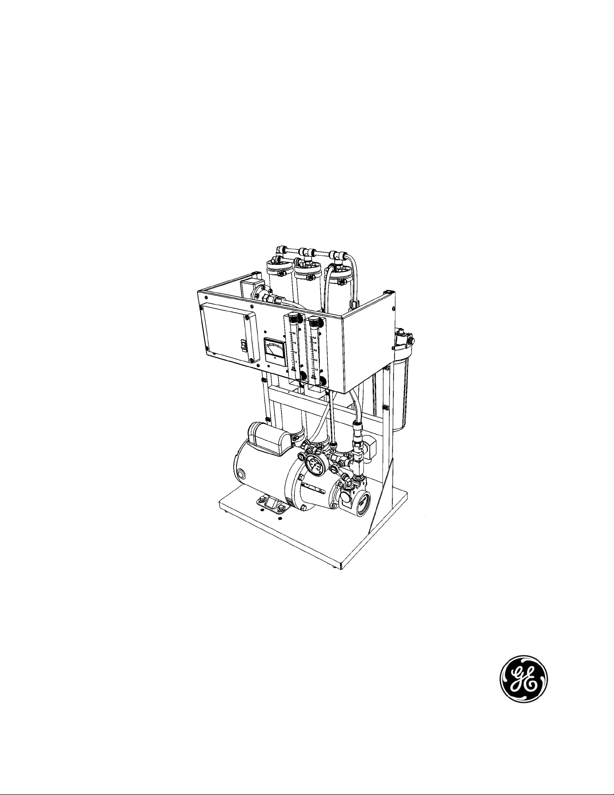
OSMONICS
E2/EZ2 SERIES
TM
WATER PURIFICATION
MACHINES
INSTALLATION, OPERATION,
AND MAINTENANCE
MANUAL
GE Infrastructure
Water & Process Technologies
Page 2
Distributor
Information
Distributor:
Contact:
Phone:
Fax:
Email:
Machine Information
Installation Date:
Model Number:
Serial Number:
Service
Assistance
Consult the Troubleshooting Section of this manual
(Section 2.19). If the problem cannot be identified and corrected, contact your distributor. Prior to making the call, have the
following information available:
Model Number Daily Log Sheets
Serial Number Operating Parameters
Installation Date Description of Problem
Spar
e Parts
Contact your distributor to order spare parts. Refer to the
Spare Parts List (Technote 109).
Page 3

INSTALLATION, OPERATION,
AND MAINTENANCE MANUAL
E2/EZ2-SERIES
WATER PURIFICATION MACHINES
T
ABLE OF
CONTENTS
Page
2.0 INSTALLATION 1
2.1 Mounting the Unit 1
2.2 Plumbing 1
2.3 Plumbing Connections 1
2.4 Feed Water Requirements 2
2.5 Transporting Pure Water (Permeate) to Point-of-Use 2
2.6 Machine Control 3
2.6.1 Economy Model 3
2.6.2 Deluxe Model 3
2.7 Single-Phase Electrical 3
2.8 Machine Start-Up Preparations 3
2.8.1 Pretreatment for Water Purification 3
2.8.2 Machine Start-Up Preparation 4
2.9 Machine Start-Up 4
2.10 Recovery 7
2.11 Permeate Back Pressure Correction Factors 8
2.12 Operation and Maintenance 9
2.13 Pre-Filter Cartridge 9
2.14 Daily Flushing 9
2.15 Membrane Element Cleaning 10
2.16 Membrane Element Removal 12
2.17 Membrane Element Replacement 12
2.18 Troubleshooting 15
Page 4

LIST OF FIGURES
Page
Figure Description
2.1 Flow Control Center 6
2.2 Closed Loop Membrane Element Cleaning 11
2.3 Membrane Element Installation 13
2.4 Membrane Element Direction for Installation 14
LIST
OF
TABLES
Table Description
2.1 E2/EZ2-Series Machine Piping Connections 1
2.2 E2/EZ2-Series Feed Water Requirements 2
2.3 E2/EZ2-Series Primary Pressure Range 5
2.4 Flow Specifications for E2/EZ2-Series Machines 7
2.5 Permeate Back Pressure Correction Factors 8
NOTE
: This manual, along with all GE Infrastructure manuals, is available at
www.ge.water.com.
Page 5

1
2.0 INSTALLATION
2.1 Mounting the Unit
When installing your new GE Osmonics reverse osmosis (RO) machine, allow at least
45-inches (114.3 cm) above the machine for membrane element removal and loading. If
space is not available, the entire membrane element housing can be removed for
membrane element change-outs. If the membrane element housings are to be removed to
change-out the membrane elements, at least 25-inches (65.3 cm) is required at one end of
each membrane element housing and 6-inches (15.2 cm) behind the machine.
2.2 Plumbing
The feed water source must be able to provide water quantity and pressures to maintain an
operating feed water pressure of 30 - 60 psi (2.1 - 4.1 bar). If the feed water pressure with
the machine is in excess of 60 psi (4.1 bar) or fluctuates by more than 5 psi
(0.34 bar) a pressure regulator should be installed upstream of the machine inlet. If proper water pressure cannot be maintained to the RO, a booster pump may need to be installed
in front of the pretreatment to provide the proper water quantity and pressure for the operation of the machine.
2.3 Plumbing Connections
Connect proper size drain line to the concentrate outlet (Table 2.1, E2/EZ2-Series
Machine Piping Connections) and run to an open drain. The drain capacity needs to be
large enough to properly drain the feed water flow of the RO.
Table 2.1
E2/EZ2- Series Machine
Piping Connections
CONNECTIONS
Inlet
inch (cm)
Permeate
inch (cm)
Concentrate
inch (cm)
0.38 (0.96)
0.38 (0.96)
0.38 (0.96)
Page 6

2.4 Feed Water Requirements
The following feed water requirements must be met before installing your E2/EZ2-Series
machine to ensure quality permeate and extended membrane element life. Refer to
Table 2.2 (
E2/EZ2-Series Feed Water Requirements) for feed water information.
Table 2.2
E2/EZ2-Series Feed
Water Requirements
* American Standard for Testing Materials
2.5 T
ransporting Pure Water (Permeate) to Point-of-Use
Pure water, or permeate, is in an aggressive state and should only be transported from the
machine to the point-of-use in food grade flexible nylon, stainless steel (SS) tubing, or
polyvinyl chloride (PVC) material for the inlet, permeate, and concentrate piping sizes.
Refer to Connections (Table 2.1, E2/EZ2-Series Machine Plumbing Connections) for
inlet, permeate, and concentrate piping sizes.
W
ARNING
: MACHINE DAMAGE MAY OCCUR IF PERMEATE BACK PRES-
SURE EXCEEDS 60 PSI (4.1 BAR) DURING OPERATION.
2
Temperature
Inlet Pressure
Chlorine
(continuous feed)
Operating pH
Silt Density Index
(SDI)
Typical: 50° - 85°F (10° - 29°C)
Limits: 33° - 104°F (0.60° - 40°C)
Minimum: 30 psig (2.1 barg)
Maximum: 60 psig (4.1 barg)
0 parts per million (ppm)
5.5 - 8.5
Less than or equal to 5 to minimize
membrane element fouling and
extend cleaning intervals. Refer to
ASTM* Standard D4189.
Page 7

2.6 Machine Control
2.6.1 Economy Model
To remotely control the Economy Model (ECN) with float switches and/or pretreatment lockout, remove the jumper between terminals 4 and 5 and wire in the
float switches or pretreatment components in series. After all field wiring is complete and complies with local and national electrical codes, move onto
Section 2.7 (Single-Phase Electrical).
NOTE
: External control contacts are normally closed, dry contacts.
2.6.2 Deluxe Model
To remotely control the Deluxe Model (DLX), with float switches and/or pretreatment lockout, remove the jumper between terminals 2 and 3 and wire in the
float switches and pretreatment in series. After all field wiring is complete and
complies with local and national electrical codes, move onto Section 2.10
(Pretreatment for Water Purification).
NOTE
: External control contacts are normally closed, dry contacts.
2.7 Single-Phase Electrical
Always check voltage tag on the machine to ensure the correct voltage and amperage is
available.
The E2/EZ2-Series machines are shipped as either 120 Volt 60 Hertz or 220 Volt
50 Hertz from the factory. Machines should always be connected to a 15 Amp singlephase dedicated circuit. The circuit provided should be a separately fused disconnect with
the proper protection for the Hp and Amp draws of the machine. Reverse osmosis (RO)
machines with 115 Volt circuit include an 8-foot (2.4 m) electrical cord which plugs into
a single-phase outlet. All machines shipped with a 220 VAC single-phase power requirement are shipped with an 8-foot (2.4 m) electrical cord, but customers must provide
electrical plug. All field wiring must comply with applicable local and national electrical
codes.
2.8 Machine S
tart-Up Preparations
2.8.1 Pretreatment for Water Purification
A water analysis of your feed water should have been performed, as part of the
planning and engineering that went into developing your RO system.
The water analysis will provide information on what type of pretreatment may be
required and what recovery the machine can be run at on the feed water provided. If the machine is moved to a different water source, a new water analysis
should be taken before operating the machine.
3
Page 8

Your RO is designed to operate on softened tap feed water with an SDI of 5 or
less. The pH should be in a range of 5.5 - 8.5. Exposure to any levels of chlorine may cause irreversible damage to the Thin-layer composite (TLC) polyamide
(PA) membrane elements in your machine. Daily water checks are recommended to ensure the integrity of your pretreatment and RO system. Refer to
Table 2.2 (E2/EZ2-Series Feed Water Requirements).
2.8.2 Machine Start-Up Preparation
Check the function and integrity of your pretreatment equipment. Ensure that
your water softener and activated carbon filters have been leaked checked and
properly flushed, before starting up your RO machine.
W
ARNING: IMPROPERLY FLUSHED PRETREATMENT MAY
CAUSE SERIOUS RO MACHINES PROBLEMS AT
START-UP.
W
ARNING: NEVER OPERATE THE MACHINE WITH THE CON-
CENTRATE OR PERMEATE LINES BLOCKED.
SEVERE DAMAGE TO THE UNIT MAY RESULT.
2.9 Machine S
tart-Up
STEPS
1. Turn the feed water supply to the machine ON, while checking for leaks in the
pretreatment and inlet feed water lines.
2. Check to ensure power to the motor is de-energized and the ON/OFF button, on
the machine, is in the ON position.
3. Plug in the factory-supplied power cord.
NOTE
: Fifty (50) Hertz models require customer supplied plug compatible
with existing outlet.
4. For initial start-up, redirect the permeate and concentrate lines to the drain for
start-up flush.
5. Open the concentrate and recycle flow control valves two (2) complete turns.
These valves are positioned on the flow control plumbing (Figure 2.1, Flow
Control Center).
W
ARNING
: ONCE MACHINE IS OPERATING, FLUSH CONCEN-
TRATE AND PERMEATE TO THE DRAIN FOR
20 - 30 MINUTES. FLUSHING ENSURES ALL BIOCIDES
AND CONTAMINATES ARE REMOVED FROM THE
MEMBRANE ELEMENTS.
4
Page 9

6. Turn the ON/OFF button on the machine ON.
7. As the pump starts to build pressure, begin to adjust the valves in the following
manner: start by slowly closing the concentrate valves while slowly opening the
recycle valve (Figure 2.1, Flow Control Center).
CAUTION
: Monitor machine to ensure inlet pressure of 30 - 60 psi
(2.1 - 4.1 bar) is maintained during operation.
8. After 20 - 30 minutes of flushing permeate to the drain, ensure all chemical
residue has been removed before hooking up to point of use.
While operating, the pressure range should never operate outside of the pressure
ranges displayed in Table 2.3 (E2/EZ2-Series Primary Pressure Range).
Table 2.3
E2/EZ2-Series
Primary Pressure Range*
* Primary pressure temperature for normal operation is 77°F (25°C).
CAUTION
: The E2/EZ2-Series must not operate outside the ranges listed
above.
NOTE: Optimum recovery will vary according to feed water quality.
The concentrate valve is drilled, and when completely closed the machine is running at the correct concentrate flow for a 75% recovery (Table 2.4, Flow
Specifications for E2/EZ2-Series Machines).
If the temperature of the inlet feed water is not 77°F (25°C) use the Temperature
Correction Factor Table (Technote 113). The proper adjustment of the recycle and
concentrate valves are critical to the correct operation of the machine.
5
Operating
Pressure
Operating
Range
220 psi
(15.2 bar)
165 - 250 psi
(114. - 17.2 bar)
E2/EZ2-Series
Page 10

9. Complete the Start-Up Data Sheet (Technote 101). The Start-Up Data Sheet and
the Daily Log Sheet (Technote 106) are invaluable in diagnosing the performance
of the equipment, and must be be kept for reference. If you have questions concerning the operation of your machine or the method of data recording, contact
your distributor or the manufacturer.
Figure 2.1
Flow Control Center
CAUTION: Once the machine is running, with orifices, adjust pressures and
flows to the correct measure, flush machine to drain for
30 - 45 minutes.
CAUTION
: The E2/EZ2-Series machines are designed to run at 50% recov-
ery. To confirm flows are correct, check Table 2.4 (Flow
Specifications for E2/EZ2-Series Machines). To correct any
temperature variations, check Table 2.4. If your E2/EZ2-Series
machine is operating under permeate back pressure to point of
use, refer to Table 2.5 (E2/EZ2-Series Permeate Back Pressure
Correction Factors).
CAUTION
: Machine performance is based on a feed water temperature of
77°F (25°C). If feed water temperature is other than
77°F (25°C), reference Table 2.4 (Temperature Correction
Factors) to confirm machine’s performance
6
Pressure Gauge
Feed Water
Inlet
Concentrate Valve
Recycle Valve
Page 11

2.10 Recovery
The machine flow specifications listed below are based on 77°F (25°C).
Table 2.4
E2/EZ2 - Series
Flow Specifications for
Machines
7
2100/
2535
33 - 50%
95 - 98%
1.8 (0.40)
1.8 - 1.2
(0.41 - 0.82)
1400/
1690
33 - 50%
95 - 98%
1.2 (0.27)
1.2 - 0.8
(0.27 - 0.54)
1125
33 - 50%
95 - 98%
0.9 (0.20)
0.9 -0.6
(0.20 - 0.13)
620/
750
33 - 50%
95 - 98%
0.5 (0.11)
0.5 - 0.3
(0.11 - 0.07)
0375
33 - 50%
95 - 98%
0.3 (0.07)
0.3 - 0.2
(0.07 -0.14)
E2/EZ2-Series
Units
Recovery Range
Rejection Rate
Permeate Rate
gpm (m
3
/h)
Concentrate Rate
gpm (m
3
/h)
Page 12

2.11 Permeate Back Pressure Correction Factors
It is often necessary to operate RO machines with permeate back pressure. Permeate back
pressure will decrease permeate production. See Table 2.5 (Permeate Back Pressure
Correction Factors) to calculate loss of permeate.
Table 2.5
E2/EZ2-Series
Permeate Back
Pressure Correction
Factors
W
ARNING: IF PERMEATE BACK PRESSURE EXCEEDS 60 PSI (4.1 BAR)
MACHINE DAMAGE MAY OCCUR.
W
ARNING: INSTALLING A CHECK VALVE WILL PREVENT REVERSE
FLOW THROUGH THE MEMBRANE ELEMENT WHEN THE
MACHINE IS NOT IN OPERATION. REVERSE FLOW, WHEN
THE MACHINE IS NOT IN OPERATION, CAN SEVERELY
DAMAGE THE MEMBRANE ELEMENTS.
8
BACK
PRESSURE
10 psig (0.7 barg)
20 psig (1.4 barg)
30 psig (2.0 barg)
40 psig (2.7 barg)
50 psig (3.4 barg)
60 psig (4.1 barg)
PRESSURE
CORRECTION
FACTOR (PCF)
0.95
0.90
0.80
0.70
0.60
0.50
% LOSS OF
PERMEATE
FLOW
5%
10%
15%
20%
25%
30%
Page 13

2.12 Operation and Maintenance
The operation and maintenance of an E2/EZ2-Series RO machine requires regular data
recording and routine preventative maintenance. It cannot be emphasized enough the
importance of filling out the Daily Log Sheet (Technote 106) during each operating shift.
A Start-Up Data Sheet (Technote 101) should have been completed at start-up. The StartUp Data Sheet contains pertinent facts on the operation of your machine. These two
records are invaluable in diagnosing the performance of the equipment, and must be kept
for reference. If you have questions concerning the operation of your machine or the
method of data recording, contact the manufacturer.
Three preventative maintenance procedures, which must be done on a regular basis, are
as follows:
1. Change the pre-filter cartridges as needed.
2. The machine needs to run and flush for at least 10 minutes every 72 hours, clock
time.
3. Clean the RO membrane elements with approved cleaners at least quarterly,
depending on feed water quality.
2.13 Pre-filter Cartridge
A 1 micron pre-filter cartridge is factory installed to protect the membrane elements and
valves from particles, which may be in the feed water. To order replacements, see the
Spare Parts List (Technote 109).
A pressure drop across the filter of 8 psi (0.55 bar) or more during operation indicates that
the pre-filter cartridge(s) need changeing. Use only GE approved filters rated at 2 microns
or less. Refer to Technote 109 (Spare Parts List) for pre-filter cartridge replacements. Do
not attempt to clean used pre-filter cartridges.
NOTE
: Failure to perform normal preventative maintenance procedures will void
machine warranty.
2.14 Daily Flushing
A manually flush of the E2/EZ2-Series must be done machine daily.
To flush the machine:
NOTE
: During flushing procedure, the machine must be running.
STEPS
1. With the machine running, open the concentrate valve 1/2 -3/4 of a turn
(Figure 2.1, Flow Control Center).
9
Page 14

2. Allow the machine to operate with the concentrate valve open 1/2 - 3/4- of a turn
(Step 1) for 10 - 15 minutes.
3. After 10 - 15 minutes, return the concentrate valve to its previous setting, and
return to normal operation.
CAUTION
: When opening the concentrate valve, never allow the machine’s
primary pressure to drop more than 10% below normal operating
pressure (Table 2.3, E2/EZ2-Series Primary Pressure Range).
2.15 Membrane Element Cleaning
Periodic cleaning of the machine with appropriate membrane element cleaners will prolong the life of the membrane elements. Local conditions will determine the frequency of
cleaning. Cleaning may be required when:
1. The permeate quality begins to decline.
2. The reading on the final pressure gauge begins to change noticeably.
GE recommends that you clean your E2/EZ2-Series RO machine every quarter. You may
have to clean the RO machine more frequently, depending on the quality of your feed
water. Cleaning of the membrane elements is vital because contanimants can build-up on
the membrane element surfaces, reducing the permeate flow rate and affecting the quality of the permeate.
To clean the membrane elements:
NOTE
: It is always best to start with the acid or inorganic cleaner.
STEPS
1. Remove and replace the pre-filter cartridge (Section 2.14, Pre-filter Cartridge).
NOTE
: For best results, GE recommend pre-filters be replaced before and after
cleaning.
2. In a clean container, collect approximately five (5) gallons (19 Liters) of RO
permeate water.
3. Turn machine and water supply OFF.
10
Page 15

Figure 2.2
E2/EZ2-Series
Closed Loop Membrane
Element Cleaning
NOTE
: This clean container will be referred to as the Clean-In-Place (CIP)
container.
4. Disconnect and route the inlet, permeate, concentrate lines from their service
locations to the CIP container (Figure 2.2 E2/EZ2-Series Closed Loop Membrane
Element Cleaning.
5. Connect the CIP feed line to the E2/EZ2-Series machine inlet feed water port
(Figure 2.2, E2/EZ2-Series Closed Loop Membrane Element Cleaning).
6. Mix the appropriate cleaning compound in the 5 gallons of permeate water, in the
CIP container, according to the cleaning label instructions.
7. Turn machine ON and allow machine to recirculate the cleaning solution for
10 - 15 minutes.
NOTE
: The incoming feed pressure should be 30 psi (2.1 bar).
As machine starts up it will achieve prime and begin to draw solution into the
machine and circulate the solution back into the CIP container.
If the machine makes noise or primary pressure does not climb to normal operating pressure (Table 2.3, E2/EZ2-Series Primary Pressure Range) turn machine
OFF. Refer to Troubleshooting (Section 1.18). Once pressure range is corrected,
continue start-up procedure.
As the machine runs normally check CIP tank to ensure that the CIP inlet line to
the machine is submerged in the cleaning solution, so the pump prime will not be
lost.
11
Page 16

8. After circulaiting the macine for 10 - 15 minutes or solution has reached
95°F (35°C), shut machine OFF.
9. Dump solution. Repeat Setps 6 - 8.
10. With machine OFF (Step 8), let cleaning solution dwell in machine for
15 - 30 minutes.
11. After 15 - 30 minutes, reconnect feed to RO unit and connect concentrate and permeate to drain. Turn machine ON and flush permeate water to the drain for
10 - 15 minutes.
This ensures that all cleaning agents have been removed for the machine.
12. If cleaning with an organic cleaner, return to Step 1 and repeat Steps 1 -11.
13. After completing cleaning (normal and organic) and flushing to the drain reconnect permeate to the point of use, concentrate to the drain, and reconnect feed to
the RO unit.
W
ARNING: LOSS OF PRIME DURING SUCTION CLEANING MAY
RESULT IN SERIOUS DAMAGE TO THE PUMP.
NOTE
: As previously mentioned, the manufacturer recommends use of a CIP
or booster pump to circulate the cleaning solution during membrane
element cleaning.
2.16 Membrane Element Replacement
CAUTION: Replacement membrane elements are shipped from the factory in a plas-
tic bag with a small amount of bactericide solution to prevent biological
growth. When installing the membrane elements, always provide adequate ventilation and wear gloves while handling the membrane elements
as recommended. The membrane elements must be kept moist at all
times to prevent possible damage to the membrane element material.
STEPS
1. Remove the top end caps and clamps from the membrane element housings
(Figure 2.4, Membrane Element Installation). Lubricate all O-rings and brine
seals, and the polyvinyl chloride (PVC) membrane element stems (stingers) with
a non-petroleum based lubricate (i.e., glycerin or poly water).
2. Load the down flow membrane elements first, by inserting the membrane element
into the membrane element housing with the brine seal end of the membrane element up. Slowly turn the membrane element as you lower it into the membrane
12
Page 17

element housing. As you reach the bottom of the housing slowly guide the PVC
stem or stinger on the end of the membrane element into the head of the end cap.
As the membrane element slides into the housing the brine seal will be on the top
(Figure 2.4, Direction of Membrane Element Installation).
Figure 2.3
Membrane Element
Installation
3. Next, load the up flow membrane elements, by lubricating all brine seals, O-rings,
and the membrane element stingers. With the up flow membrane element and the
brine seal will be on the bottom of the membrane element. Turn the membrane
element slowly as you lower it down into the housing. As with the down flow
membrane element, one must slowly guide the PVC stinger on the end of the
membrane element into the end cap.
4. Reinstall the end caps by using non-petroleum based lubricant to lubricate the Oring inside the end cap. Reinstall the end cap on the membrane element by first,
aligning the stinger into the hole in the end cap and then turn the end cap slowly
clockwise, as you push it down into the membrane element housing.
5. Reattach the housing clamp and tighten.
6. Reattach the feed line and flush permeate and concentrate lines to the drain for
25 - 30 minutes.
7. Take appropriate tests to insure biocide has been flushed from the machine.
8. Reconnect permeate line to point-of-use.
9. The machine is now ready for operation.
13
Page 18

Figure 2.4
Membrane Element
Direction for
Installation
14
Page 19

2.17 Troubleshooting
This troubleshooting guide can assist you in identifying common operating problems you may
experience with your machine. The operator can easily correct may of these problems, however,
for those that persist or are not understood you should contact the GE Customer Support Center.
Have the following information available when calling the Customer Support Center:
1. Machine installation date
2. Model number
3. Serial number
4. Detailed description of problem.
15
REMEDIES
Open feed water valve. Check
feed water valve for restrictions
in feed plumbing.
Replace pre-filter cartridge.
Flush and/or clean machine.
Verify valve receiving power
when machine is ON. Clean or
replace solenoid valve.
Verify proper voltage is present.
Check fuses and circuit
breakers.
Contact your distributor for
replacement or repair of pump
or motor.
POSSIBLE CAUSES
Insufficient feed water pressure
or flow
Clogged pre-filter cartridge
Dirty or fouled membrane
elements
Inlet solenoid valve not
opening
Insufficient electrical power
Pump or motor not operating
correctly
PROBLEM
Low operating pressure
TROUBLESHOOTING GUIDE
Page 20

16
REMEDIES
Refer to Section 2.9 for proper-
ly setting concentrate and
recycle valves
See above.
Check the water temperature.
If needed, install a hot/cold
tempering valve. Permeate
production rate is dependent on
77°F (25°C). Refer to Section
2.5 (Temperature Correction
Factor).
Refer to Section 2.18 for cor-
rect membrane element
installation procedure.
Membrane elements with
damaged brine seals may be
returned for repair. For low
permeate production, it is
wise to test the permeate pro-
duction of each membrane
element.
Refer to Section 2.18 for cor-
rect membrane element
installation.
Flush and/or clean the
machine.
Reduce permeate line backpressure. Check for restric-
tions in permeate plumbing.
POSSIBLE CAUSES
Concentrate or recycle valve to
far open
Low operating pressure
Machine operating on cold
water
Membrane elements installed
incorrectly
Brine seal has “rolled” or been
damaged
Dirty or fouled membrane
elements
Backpressure on the permeate
line
PROBLEM
Low operating pressure
(continued)
Low permeate production
.
TROUBLESHOOTING GUIDE
Page 21

17
REMEDIES
Install new membrane ele-
ment(s). See Spare Parts List
(Section 2.20).
Check the flow rate manually
with a stop watch and a cali-
brated container.
Flush and/or clean machine.
Replace the O-rings, check
the sealing surfaces on the
O-ring groove and end caps.
Replace damaged parts.
Replace with new membrane
elements. See Spare Parts
List (Section 2.20).
Calibrate the meter with a DS
standard solution or check the
readings with another conductivity meter. Replace or clean
the probe. Check the connec-
tions between the probe and
monitor. Refer to Section
2.16.2 (Deluxe Model).
Ensure machine is
plugged in.
POSSIBLE CAUSES
Useful life of membrane
element(s) expired
Inaccurate permeate flow meter
(DLX only)
Dirty or fouled membrane
element (s)
O-rings on membrane ele-
ment(s) unseated or
damaged parts
Useful life of membrane ele-
ment(s) expired
Change in incoming
water quality
No power to machine
PROBLEM
Low permeate production
(continued)
Low concentrate flow with
normal or high operating
pressure
Declining rejection
(high permeate
conductivity)
ON/OFF switch ON:
machine not running
TROUBLESHOOTING GUIDE
Page 22

18
REMEDIES
The storage tank may be full.
The switch control may
require adjustment.
Allow the machine to cool.
Check the Amp draw to the
machine.
Check the fuses or circuit
breakers; measure the volt-
age. Contact your distributor
for service.
Disconnect and clean the
concentrate valve.
Check for blockage of the
concentrate flow at the inlets
and outlets of membrane
element housings.
Ensure that the anti-telescop-
ing device (ATD) is intact.
Flush and/or clean the
machine.
POSSIBLE CAUSES
Pressurized storage switch or
storage tank float switch cut
power to machine
Thermal overload of motor
Pump motor failure
Dirty concentrate valve
Restricted flow after pump
outlet
Telescoped membrane element
covering membrane element
housing
Fouled or dirty membrane
elements
PROBLEM
ON/OFF switch ON:
machine not running
(continued)
Pressure does not drop when
concentrate valve opened
Excessive pressure drop
acrosse membrane
element(s)
[over 50 psi (3.5 bar)]
TROUBLESHOOTING GUIDE
Page 23

19
REMEDIES
Ensure valve is not getting any
power when machine is OFF.
Replace inlet solenoid valve.
POSSIBLE CAUSES
Inlet solenoid valve not fully
closed
PROBLEM
Flow through machine while
power is OFF
TROUBLESHOOTING GUIDE
Page 24

Page 25

For more information call 952-933-2277 or 800-848-1750 in the U.S., or visit www.gewater.com.
© 2004, General Electric Company. All rights reserved.
P/N 1227273 Rev.C
North American Sales Euro/Africa Sales Asia/Pacific Sales
5951 Clearwater Drive 230 rue Robert Schurman 1044/8 SOI 44/2
Minnetonka, MN ZA des Uselles Sukhumvit Road Parkanog
55343-8995 77350 Le Mée sur Seine Bangkok 10110
USA FRANCE THAILAND
(952) 933-2277 Phone +33 1 64 10 2000 Phone +66 2 38 14213 Phone
(952) 933-0141 Fax +33 1 64 10 3747 Fax +66 2 39 18183 Fax
GE Infrastructure
Water & Process Technologies
 Loading...