

Page 1

g
GEH-6632
GE Industrial Systems
™
EX2100
Excitation Control
User’s Guide
Page 2

Page 3
g
Document: GEH-6632
Issue Date: 2000-09-30
GE Industrial Systems
™
EX2100
Excitation Control
User’s Guide
Page 4

© 2000 General Electric Company, USA.
All rights reserved.
Printed in the United States of America.
These instructions do not purport to cover all details or variations in equipment, nor to
provide for every possible contingency to be met during installation, operation, and
maintenance. If further information is desired or if particular problems arise that are not
covered sufficiently for the purchaser’s purpose, the matter should be referred to GE
Industrial Systems, Salem, Virginia, USA.
This document contains proprietary information of General Electric Company, USA and
is furnished to its customer solely to assist that customer in the installation, testing,
operation, and/or maintenance of the equipment described. This document shall not be
reproduced in whole or in part nor shall its contents be disclosed to any third party
without the written approval of GE Industrial Systems.
Document Identification: GEH-6632
EX2100 is a trademark of General Electric Company, USA.
Cimplicity® is a registered trademark of GE Fanuc Automation North America, Inc.
Ethernet™ is a trademark of Xerox Corporation.
Mate-N-Lok® is a registered trademark of Amp Incorporated.
Windows NT® is a registered trademark of Microsoft Corporation.
Page 5
••••
Safety Symbol Legend
Indicates a procedure, condition, or statement that, if not
strictly observed, could result in personal injury or death.
Indicates a procedure, condition, or statement that, if not
strictly observed, could result in damage to or destruction of
equipment.
Note Indicates an essential or important procedure, condition, or statement.
EX2100 User's Guide GEH-6632 Safety Symbol Legend
a
Page 6
••••
This equipment contains a potential hazard of electric shock
or burn. Only personnel who are adequately trained and
thoroughly familiar with the equipment and the instructions
should install, operate, or maintain this equipment.
Isolation of test equipment from the equipment under test
presents potential electrical hazards. If the test equipment
cannot be grounded to the equipment under test, the test
equipment’s case must be shielded to prevent contact by
personnel.
To minimize hazard of electrical shock or burn, approved
grounding practices and procedures must be strictly followed.
To prevent personal injury or equipment damage caused by
equipment malfunction, only adequately trained personnel
should modify any programmable machine.
b
Safety Symbol Legend GEH-6632 EX2100 User’s Guide
Page 7
g
g
g
g
Reader Comments
Reader Comments
Reader Comments
Reader Comments
General Electric Company
General Electric Company
General Electric Company
General Electric Company
We welcome comments and suggestions to make this publication more useful.
To:
GE Industrial Systems
Documentation Design, Rm. 291
1501 Roanoke Blvd.
Salem, VA 24153-6492 USA
Fax: 1-540-387-8651
(GE Internal DC 8-278-8651)
Your Name Today’s Date
Your Company’s Name and Address Job Site
GE Requisition No.
Publication No.Your Job Function / How You Use This Publication
Publication Issue/Revision Date
General Rating
Excellent Good Fair Poor Additional Comments
Contents ¡¡¡¡_____________________________________________________________
Organization ¡¡¡¡_____________________________________________________________
Technical Accuracy ¡¡¡¡_____________________________________________________________
Clarity ¡¡¡¡_____________________________________________________________
Completeness ¡¡¡¡_____________________________________________________________
Drawings / Figures ¡¡¡¡_____________________________________________________________
Tables ¡¡¡¡_____________________________________________________________
Referencing ¡¡¡¡_____________________________________________________________
Readability ¡¡¡¡_____________________________________________________________
If needed, how can we contact you?
Fax No.
Phone No.
E-mail
Address
Specific Suggestions
Page No. Comments
______ __________________________________________________________________________________
______ __________________________________________________________________________________
______ __________________________________________________________________________________
______ __________________________________________________________________________________
______ __________________________________________________________________________________
______ __________________________________________________________________________________
Other Comments (What you like, what could be added, how to improve, and such.) ________________________________________________
___________________________________________________________________________________________
___________________________________________________________________________________________
___________________________________________________________________________________________
___________________________________________________________________________________________
___________________________________________________________________________________________
___________________________________________________________________________________________
Overall grade (Compared to publications from other manufacturers of similar products, how do you rate this publication?)
¡ Superior ¡ Comparable ¡ Inferior ¡ Do not know Comment ____________________________________________
(Corrections, information that could be expanded on, and such.)
Detach and fax or mail to the address noted above.
Page 8

.........................................................................Fold here and close with staple or tape ..........................................................................................
____________________________
____________________________
____________________________
GE Industrial Systems
Documentation Design, Rm. 291
1501 Roanoke Blvd.
Salem, VA 24153-6492 USA
...........................................................................................
Place
stamp
here.
Fold here first.........................................................................................................
Page 9

••••
Contents
Chapter 1 Equipment Overview 1-1
Introduction............................................................................................................................ 1-1
System Overview ................................................................................................................... 1-2
Hardware Overview ...............................................................................................................1-5
Software Overview................................................................................................................. 1-6
Technical Characteristics .......................................................................................................1-6
How to Get Help .................................................................................................................... 1-8
Related Documents ................................................................................................................ 1-8
Chapter 2 Functional Description 2-1
Introduction............................................................................................................................ 2-1
Exciter Hardware ................................................................................................................... 2-2
Exciter Configurations ........................................................................................................... 2-3
Power Conversion Cabinet..................................................................................................... 2-5
Auxiliary Cabinet................................................................................................................... 2-8
Control Cabinet.................................................................................................................... 2-10
Exciter Software................................................................................................................... 2-17
Operator Interface ................................................................................................................2-23
Document Distribution............................................................................................. 1-8
Manual Ac Disconnect (Optional)...........................................................................2-5
Power Conversion Module (PCM).............................................................................2-5
Gate Pulse Amplifiers (EGPA Board) ..................................................................... 2-6
Main Dc Contactors. 41A or 41A/41B (Optional)................................................... 2-7
Free Wheeling Diode De-excitation ........................................................................ 2-7
Ac Line-to-Line Filters ............................................................................................ 2-8
De-excitation Module (EDEX) ................................................................................ 2-8
Shaft Voltage Suppressor......................................................................................... 2-9
Field Flashing Module ............................................................................................. 2-9
Field Ground Detector (EXAM and EGDM)........................................................... 2-9
High Voltage Interface – HVI.................................................................................. 2-9
Diagnostic Interface (Keypad)............................................................................... 2-10
Control Module...................................................................................................... 2-11
Simplex Control System ........................................................................................ 2-12
Redundant Control System .................................................................................... 2-13
Control Power Supplies ......................................................................................... 2-14
Auto Reference – AUTO REF............................................................................... 2-20
AVR Setpoint – EXASP ........................................................................................ 2-20
Automatic Voltage Regulator – AVR.................................................................... 2-20
Manual Reference – MANUAL REF .................................................................... 2-21
Field Voltage and Current Regulators - FVR & FCR............................................ 2-21
Under Excitation Limiter – UEL ........................................................................... 2-22
Power System Stabilizer – PSS.............................................................................. 2-22
Turbine Control HMI.............................................................................................2-23
Control System Toolbox (toolbox)........................................................................2-23
EX2100 User’s Guide GEH-6632 Contents
i
Page 10

••••
Chapter 3 Printed Wiring Boards Overview 3-1
Introduction............................................................................................................................ 3-1
Control Boards ....................................................................................................................... 3-2
Exciter Backplane (EBKP) ...................................................................................... 3-2
Digital Signal Processor Board (DSPX) .................................................................. 3-2
ACLA Board............................................................................................................ 3-4
EISB Board.............................................................................................................. 3-4
EMIO Board ............................................................................................................ 3-4
ESEL Board............................................................................................................. 3-5
I/O Terminal Boards .............................................................................................................. 3-5
EPCT Board............................................................................................................. 3-5
ECTB Board ............................................................................................................ 3-6
EXTB Board ............................................................................................................ 3-6
EDCF Board ............................................................................................................ 3-6
EACF Board ............................................................................................................ 3-7
Bridge and Protection Boards and Modules........................................................................... 3-7
EGPA Board ............................................................................................................ 3-7
EXCS Board ............................................................................................................ 3-7
EDEX Board............................................................................................................ 3-8
EGDM Module ........................................................................................................ 3-8
EXAM Module ........................................................................................................ 3-9
Power Supply Boards.............................................................................................................3-9
EPDM Module......................................................................................................... 3-9
EPBP Backplane...................................................................................................... 3-9
EPSM Module ....................................................................................................... 3-11
DACA – Ac to Dc Converter................................................................................. 3-11
Related Board Publications.................................................................................................. 3-11
Chapter 4 Terminal Board I/O and Equipment Connections 4-1
Introduction............................................................................................................................ 4-1
Power Connections and Analog I/O....................................................................................... 4-2
Power Potential Transformer Inputs ........................................................................ 4-3
Potential and Current Transformer Inputs................................................................ 4-3
Analog Input ............................................................................................................ 4-3
Customer Contact I/O ............................................................................................................4-4
Power Supply Inputs .............................................................................................................. 4-6
Line Filter Connections.......................................................................................................... 4-7
Exciter Internal I/O ................................................................................................................ 4-8
Exciter AC Feedback............................................................................................... 4-8
Exciter DC Feedback ............................................................................................... 4-8
De-Excitation ....................................................................................................................... 4-11
Crowbar................................................................................................................................ 4-14
Field Ground Detector.......................................................................................................... 4-14
Field Flashing....................................................................................................................... 4-16
Dc Field Flashing Settings ..................................................................................... 4-16
Flashing Control Sequence .................................................................................... 4-16
Shaft Voltage Suppressor..................................................................................................... 4-18
Data Highway Connections.................................................................................................. 4-19
Control System Toolbox Connection................................................................................... 4-20
Chapter 5 Diagnostic Interface-Keypad 5-1
Introduction............................................................................................................................ 5-1
Using the Pushbuttons............................................................................................................ 5-2
Reading the Display ............................................................................................................... 5-5
ii
Contents GEH-6632 EX2100 User’s Guide
Page 11

••••
Changing Display Units........................................................................................... 5-7
Adjusting Display Contrast...................................................................................... 5-7
Status Screen .......................................................................................................................... 5-8
Reading the Meters .................................................................................................. 5-8
Alternate Status Screen (Display I/O).................................................................................... 5-8
Using the Menus .................................................................................................................... 5-9
Viewing and Resetting Faults ................................................................................................ 5-9
Editing Parameters ............................................................................................................... 5-10
Parameter Backup.................................................................................................. 5-11
Firmware and Hardware Information................................................................................... 5-13
Protecting the Keypad.......................................................................................................... 5-14
Modifying the Protections...................................................................................... 5-14
Appendix A Warranty and Renewal Parts A-1
Introduction........................................................................................................................... A-1
Identifying the Part................................................................................................................ A-2
Renewal Parts List .................................................................................................. A-2
Part Number Structure ............................................................................................ A-2
Warranty Terms .................................................................................................................... A-4
How to Order Parts ............................................................................................................... A-5
Data Nameplate....................................................................................................... A-5
ML Number ............................................................................................................ A-5
Appendix B Ratings and Specifications B-1
Glossary of Terms
Index
EX2100 User’s Guide GEH-6632 Contents
iii
Page 12

••••
Notes
iv
Contents GEH-6632 EX2100 User’s Guide
Page 13

••••
Chapter 1 Equipment Overview
Introduction
The EX2100ä Excitation Control (EX2100 or exciter) produces the field excitation
current to control generator ac terminal voltage and/or the reactive volt-amperes. It is
a full static excitation system designed for generators on both new and retrofit steam,
gas, and hydro turbines.
This chapter introduces the exciter and defines the document contents. Its purpose is
to present a general product overview as follows:
Section/Topic Page
System Overview..................................................................................................... 1-2
Hardware Overview................................................................................................. 1-5
Software Overview .................................................................................................. 1-6
Technical Characteristics......................................................................................... 1-6
How to Get Help...................................................................................................... 1-8
Related Documents.................................................................................................. 1-8
Document Distribution ..................................................................................... 1-8
Chapter 2 Functional Description
Chapter 3 Printed Wiring Boards Overview
Chapter 4 Terminal Boards I/O and Equipment Connections
Chapter 5 Diagnostic Interface (Keypad)
Appendix A Warranty and Renewal Parts
Appendix B Ratings and Specifications
Glossary
EX2100 User’s Guide GEH-6632 Chapter 1 Equipment Overview
1-1
Page 14

••••
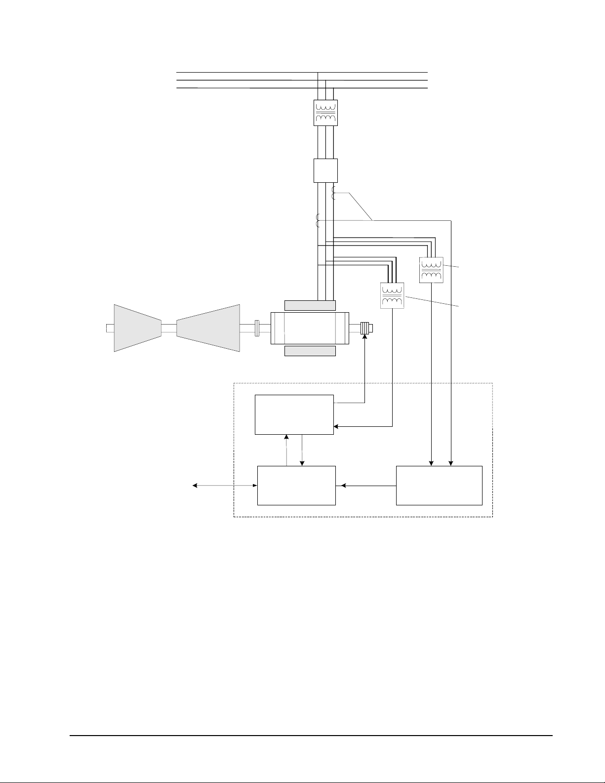
System Overview
The exciter is a flexible modular system that can be assembled to provide a range of
available output currents and several levels of system redundancy. These options
include power from a potential, compound, or auxiliary source. Single or multiple
bridges, warm backup bridges, and simplex or redundant controls are available. An
overview of the turbine generator excitation system is shown in Figure 1-1.
Power for the exciter is drawn from a power potential transformer connected to the
generator terminals, or from an excitation transformer connected to an auxiliary bus.
Generator line current and stator output voltage are the primary feedbacks to the
exciter, and dc voltage and current is the controlled output to the exciter field.
The architecture supports Ethernet LAN (Unit Data Highway) communication with
other GE equipment including the GE Control System Toolbox (toolbox) for
configuration, the turbine control, the LCI Static Starter, and the HMI (operator
interface).
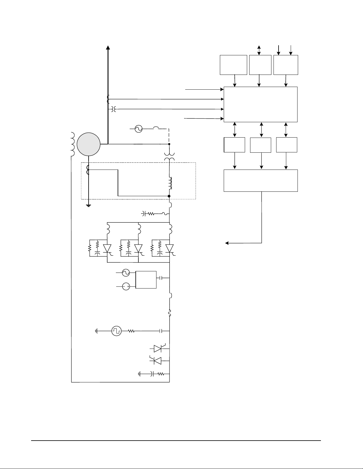
Figure 1-2 is a simplified one line diagram of the exciter showing the power source,
generator current and voltage measurements, control module, power conversion
module (PCM), and protection circuits. In the potential source system, the secondary
of the PPT is connected to the input of a 3-phase full-wave inverting thyristor bridge.
The inverting bridge provides both positive and negative forcing voltage for
optimum performance. Negative forcing provides fast response for load rejection and
de-excitation.
Either simplex or redundant
control is available.
Excitation control results from phase controlling the output of the SCR bridge
circuit. The SCR firing signals are generated by digital regulators in the controller.
In the redundant control option (Figure 1-2), either M1 or M2 can be the active
master control, while C monitors both to determine which should be the active and
which the standby controller. Dual independent firing circuits and automatic tracking
is used to ensure a smooth transfer to the standby controller.
1-2
Chapter 1 Equipment Overview GEH-6632 EX2100 User’s Guide
Page 15
••••
A
Turbine
A
)
Generator
Transmission Line
Step-up Transformer
ir Circuit Breaker (52G)
Current Transformers (CTs)
Potential
Transformers
(PTs)
Exciter Power
Potential
Transformer (PPT
Controlled
dc to Field
Data Highway to Turbine
Control, HMI, & DCS
EX2100
Exciter
Power Conversion
Module (Bridge)
Control,
Sequencing,
Protection
c Source
Figure 1-1 Overview of Generator and Exciter System
Instrumentation
EX2100 User’s Guide GEH-6632 Chapter 1 Equipment Overview
1-3
Page 16
••••
A
ACA
Load
ACA
Aux
A
r
A
Generator
PCT (3)
C
Customer I/O
CT
PT
C CB
Source
Compound
Source only
Line Filter
Current
Voltage
Bridge I/O
PPT
Linear
Reactors
(3)
C CB o
Disconnect
Diagnostic
Interface
(Keypad)
Control
M1
Data
Highway
Control
Gating Selector
Unit
I/O
M2
CDC
Control
Power
Supplies
Control
C
DC
ctive Field
Ground Detector
Deexcitation
Crowbar
Shaft Voltage Suppression
Figure 1-2. Exciter One Line Diagram
Power
Conversion
Modules
(Bridge)
Flashing
Control
DC CB or
Contactor
Shunt
PT: Potential Transformer
CT: Current Transformer
CB: Circuit Breaker
I/O: Input/Output
PCT: Power Current Transformer
PPT: Power Potential Transformer
1-4
Chapter 1 Equipment Overview GEH-6632 EX2100 User’s Guide
Page 17
••••
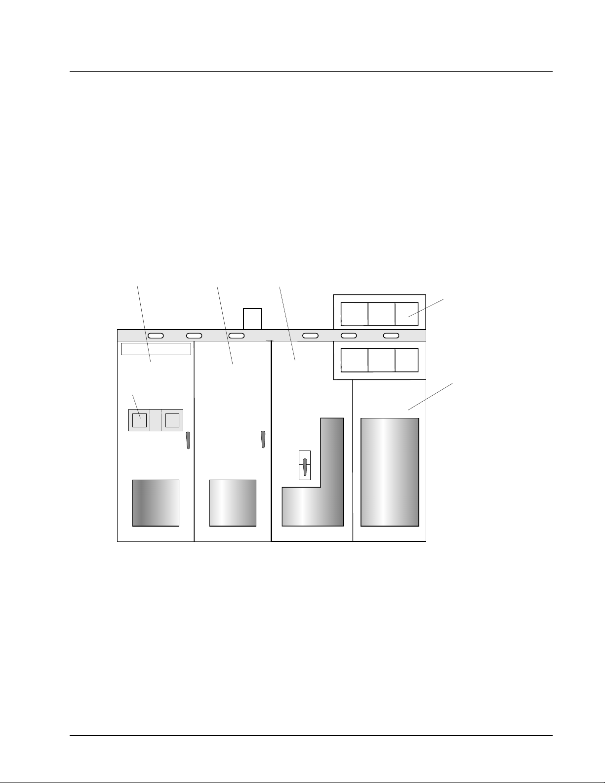
Hardware Overview
The EX2100 hardware is contained in three cabinets as follows:
• control cabinet for the control, communication, and I/O boards
• auxiliary cabinet for field flashing and protection circuits such as de-excitation
• power conversion cabinet for the power SCR cells, cooling fans, dc contactors,
The exciter's power converter consists of bridge rectifiers, resistor/capacitor filter
configurations, and control circuitry. An outside view of the cabinets is shown in
Figure 1-3. The components and bridge size vary for different excitation systems and
for the power output required.
and shaft voltage suppression
and ac disconnect
Control
Cabinet
Keypads
Auxiliary
Cabinet
Contactors &
Disconnects
Fan
Drawers
Power
Conversion
Cabinet
Figure 1-3. Exciter Cabinets
EX2100 User’s Guide GEH-6632 Chapter 1 Equipment Overview
1-5
Page 18
••••
Software Overview
Microprocessor-based controllers (ACLA and DSPX) execute the exciter control
code. The software consists of modules (blocks) combined to create the required
system functionality. Block definitions and configuration parameters are stored in
flash memory, while variables are stored in random-access memory (RAM).
The exciter application software emulates traditional analog controls. It uses an open
architecture system, with a library of existing software blocks configured from the
toolbox. The blocks individually perform specific functions, such as logic gates,
proportional integral (P.I.) regulators, function generators, and signal level detectors.
The control selects one of two modes, either generator voltage regulation (Auto
Regulation), or direct control (voltage or current, depending upon the application).
Generator protection functions are integrated into the control, including over and
under-excitation limiting, power system stabilization, and V/Hz limiting.
The blocks can be interrogated while the exciter is running by using the toolbox. The
dynamically changing I/O values of each block can be observed in operation, which
is valuable during startup or troubleshooting.
Technical Characteristics
Summary characteristics for the EX2100 are as follows; for further details refer to
Appendix B.
Unit Specific ratings are provided on equipment nameplate and
supercede all information herein.
EX2100 Characteristics Description
Power Converter Module (PCM)
Single bridge rating 1,000 and 2,000 A dc at up to 1,000 V ac
Parallel bridge rating 8,000 A dc at up to 1,500 V ac; with up to 6 bridges
Forcing requirements 150% of design Amperes (EDA) for 30 s at 40 ºC
Power Sources
Power for the PCM – Voltage source
Power Input for the PCM - VA 3251 kVA (1,000 V version)
Power for the PCM - Frequency 3-phase 50/60 Hz
Flashing power Battery source 125 V dc or 250 V dc, with up to 200 A for at least 10 s
Control power
Auxiliary bus
Generator terminals
Compound source
600 or 1,000 V ac versions
240 or 480 V ac, 50/60 Hz single-phase auxiliary source
For two ac sources, or one ac and one dc source:
Nominal 120 V ac ±15%, with 1 DACA, 10 A rms max.
Battery source, 125 V dc, range 80 – 140 V dc, 10.6 A dc max.
1-6
Chapter 1 Equipment Overview GEH-6632 EX2100 User’s Guide
Page 19

••••
Input/Output QTY
Potential transformers (PTs) 2 3-phase standard, single phase available
120 V ac nominal
1 VA nominal burden
Current transformers (CTs, 1 or 5 A) 2 Any two phases, single phase available
1 VA nominal burden
86G dedicated contact input 1 open for trip
52G dedicated contact input 1 closed for online
Trip rated contact outputs 2 At 125 V dc with relay break characteristics:
Resistive load 0.5 A
Inductive load 0.2 A
General Purpose contact inputs
6 Customer contacts, 70 V dc supplied by ECTB
General Purpose Form C contact outputs
± 10 V differential amplifier input 1
Thermal
Base controls cabinet Continuous operation in a 0 to 40 ºC ambient environment, with 5 to
Base power conversion and auxiliary
cabinet
Cabinet Dimensions & Weight
Redundant control with dual PCM
redundant converter in a three-cabinet
lineup
Weight of Converter cabinet 3,600 lbs
Weight of Total Lineup (Converter,
Control, and Auxiliary cabinets)
Cabinet type, control & auxiliary
enclosures
Cabinet type, power conversion NEMA 1 (IEC IP 20), forced air cooled
4 At 125 V dc with relay break characteristics:
Resistive load 0.5 A
Inductive load 0.1 A
95% humidity, non-condensing
Continuous operation in a 0 to 40 ºC ambient environment, with 5 to
95% humidity, non-condensing
Width 141.74 in (3600 mm)
Height 104.32 in (2650 mm)
Depth 31.5 in (800 mm)
5,600 lbs
NEMA 1 (IEC IP 20), convection cooled
Power and Control Cable Access Entrances from the top and/or bottom
EX2100 User’s Guide GEH-6632 Chapter 1 Equipment Overview
1-7
Page 20

••••
How to Get Help
“+” indicates the
international access code
required when calling from
outside of the USA.
If help is needed beyond the instructions provided in the drive system
documentation, contact GE as follows:
Related Documents
The following documents also apply to the exciter and may assist in understanding
the system.
GEI-100256C EX2100 Receiving, Storage, & Handling
GEH-6631 EX2100 Installation and Startup Guide
GEH-6633 EX2100 Troubleshooting, Preventive and Online Maintenance
GEH-6403 Control System Toolbox for Mark VI Turbine Controller
Printed Wiring Board (GEI) publications, refer to Chapter 3.
GE Industrial Systems
Product Service Engineering
1501 Roanoke Blvd.
Salem, VA 24153-6492 USA
Phone:+ 1 888 GE4 SERV (888 434 7378, United States)
+ 1 540 378 3280 (International)
Fax: + 1 540 387 8606 (All)
Document Distribution
GE Industrial Systems supplies product documents to its customers to support the
equipment provided for each requisition. The contract documents define the terms of
the document distribution.
If provided (per contract) the following documents contain requisition information
about the drive system.
• Requisition drawings, including outlines, layouts, and elementary diagrams
• Renewal parts listing
Note If differences exist between the general product documentation and the
requisition documentation, the requisition documentation should be considered the
more exact representation of your equipment or system configuration.
1-8
Chapter 1 Equipment Overview GEH-6632 EX2100 User’s Guide
Page 21

••••
Chapter 2 Functional Description
Introduction
This chapter describes the function of the EX2100 static exciter and the individual
control and protection circuits. Power supplies and the distribution of power is also
covered. The functional description information is organized as follows:
Section Page
Exciter Hardware ..................................................................................................... 2-2
Exciter Configurations............................................................................................. 2-3
Power Conversion Cabinet ...................................................................................... 2-5
Manual Ac Disconnect (Optional).................................................................... 2-5
Power Converter Module (PCM)...................................................................... 2-5
Gate Pulse Amplifiers (EGPA Board) .............................................................. 2-6
Main Dc Contactors. 41A or 41A/41B (Optional)............................................ 2-7
Free Wheeling Diode De-excitation ................................................................. 2-7
Auxiliary Cabinet..................................................................................................... 2-8
Ac Line-to-Line Filters..................................................................................... 2-8
De-excitation Module (EDEX)......................................................................... 2-8
Shaft Voltage Suppressor.................................................................................. 2-9
Field Flashing Module...................................................................................... 2-9
Field Ground Detector (EXAM and EGDM) ................................................... 2-9
High Voltage Interface – HVI .......................................................................... 2-9
Control Cabinet...................................................................................................... 2-10
Diagnostic Interface (Keyad).......................................................................... 2-10
Control Module............................................................................................... 2-11
Simplex Control System................................................................................. 2-12
Redundant Control System............................................................................. 2-13
Control Power Supplies .................................................................................. 2-14
Exciter Software .................................................................................................... 2-17
Auto Reference – AUTO REF........................................................................ 2-20
AVR Setpoint – EXASP................................................................................. 2-20
Automatic Voltage Regulator – AVR............................................................. 2-20
Manual Reference – MANUAL REF ............................................................. 2-21
Field Voltage and Current Regulators - FVR & FCR..................................... 2-21
Under Excitation Limiter – UEL .................................................................... 2-22
Power System Stabilizer – PSS ...................................................................... 2-22
Human Machine Interface (HMI) .......................................................................... 2-23
Mark VI HMI.................................................................................................. 2-23
Toolbox........................................................................................................... 2-23
EX2100 User’s Guide GEH-6632 Chapter 2 Functional Description
2-1
Page 22

••••
Exciter Hardware
The EX2100 exciter consists of the following basic components.
• Power Conversion Module (PCM) and cooling fans
• Power potential transformer (PPT) (mounted separate from exciter)
• Line-to-line filters
• Shaft voltage suppressor
• De-excitation module
• Diagnostic Interface (keypad)
• Controllers and I/O boards
• Control power supplies
Optional components that can be added to the exciter are:
• Warm backup bridge configuration
• Multibridge configuration for high current requirements
• Compound power source (separate from exciter)
• Auxiliary power source (bus-fed)
• Crowbar module (for hydro and other special applications)
• Dc Disconnect
• Field ground detector
• Redundant ac source for power supply
• Ac disconnect
• Field flashing module
• Redundant controllers providing a Triple Modular Redundant (TMR) system
• GE Control System Toolbox (toolbox) for configuration
The control hardware is basically the same for the different types of excitation. The
power conversion hardware is defined by application requirements, which therefore
determines the exciter bridge size.
2-2
Chapter 2 Functional Description GEH-6632 EX2100 User’s Guide
Page 23
••••
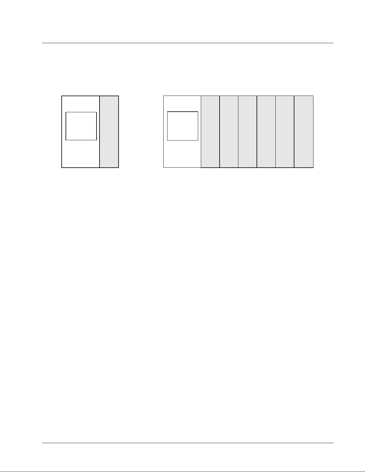
Exciter Configurations
EX2100 Exciters can be supplied with single or redundant control, and with single or
redundant bridges. Variations of the single control type are shown in Figure 2-1.
Simplex Control with
Single PCM
Control with
I/O and
Operator
Keypad
PCM
Simplex Control with
Control with
I/O and
Operator
Keypad
Figure 2-1. Simplex Control Configurations
PCM1PCM2PCM3PCM4PCM5PCM
Parallel PCMs
6
EX2100 User’s Guide GEH-6632 Chapter 2 Functional Description
2-3
Page 24
••••
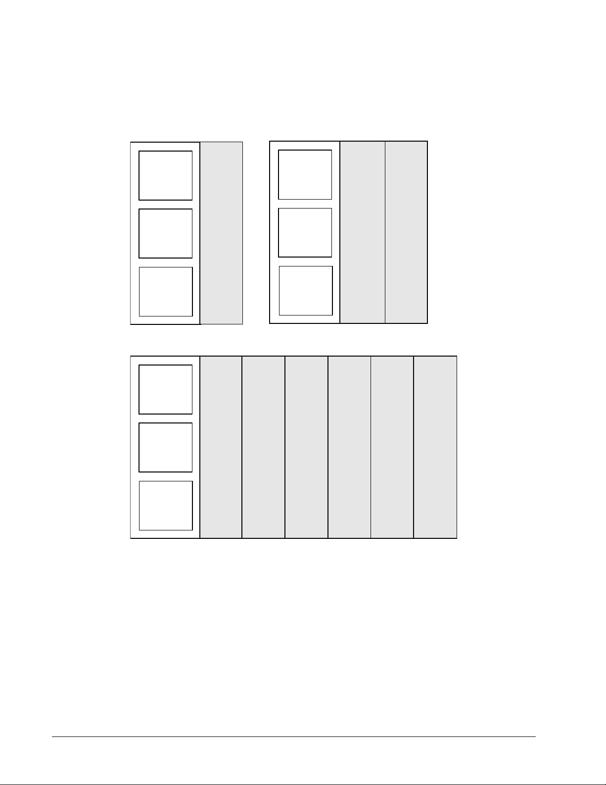
Exciters with dual (redundant) control are shown in Figure 2-2. Multiple PCMs can
be supplied in simplex, warm backup, or redundant n+1 or n+2 modes (with n+1 or
n+2 equal to 6).
Dual Control with
Single PCM
M1 Control,
I/O and
Operator
Keypad
M2 Control,
I/O and
Operator
Keypad
C Control
Selection
Logic &
Protection
Dual Control with Parallel PCMs
M1 Control,
I/O and
Operator
Keypad
PCM
PCM
1
PCM
2
Dual Control with
Warm Backup PCMs
M1 Control,
I/O and
Operator
Keypad
M2 Control,
I/O and
Operator
Keypad
C Control
Selection
Logic &
Protection
PCM
3
PCM PCM
PCM
4
PCM
5
PCM
6
M2 Control,
I/O and
Operator
Keypad
C Control
Selection
Logic &
Protection
Figure 2-2. Dual Control System Configurations
2-4
Chapter 2 Functional Description GEH-6632 EX2100 User’s Guide
Page 25

••••
Power Conversion Cabinet
The Power Conversion cabinet contains the Power Conversion Module (PCM), the
Exciter Gate Pulse Amplifier (EGPA) board, ac circuit breaker, and the dc circuit
contactor. Three-phase power for the PCM comes from a PPT external to the exciter.
The ac supply comes into the cabinet through the ac circuit breaker (if supplied), and
is filtered by 3-phase line filters in the auxiliary cabinet.
Manual Ac Disconnect (Optional)
The manual ac disconnect switch serves as a disconnect device between the
secondary of the power potential transformer and the static exciter. It is a molded
case, 3-phase, non-automatic, panel-mounted switch, which is manually operated for
isolating the ac input supply. It is a no-load disconnect device.
Power Conversion Module (PCM)
The exciter PCM includes the bridge rectifiers, dc leg fuses, thyristor protection
circuitry (for example, snubbers, filters, and fuses) and leg reactor assemblies. The
components vary for different bridge ratings based on the power output required.
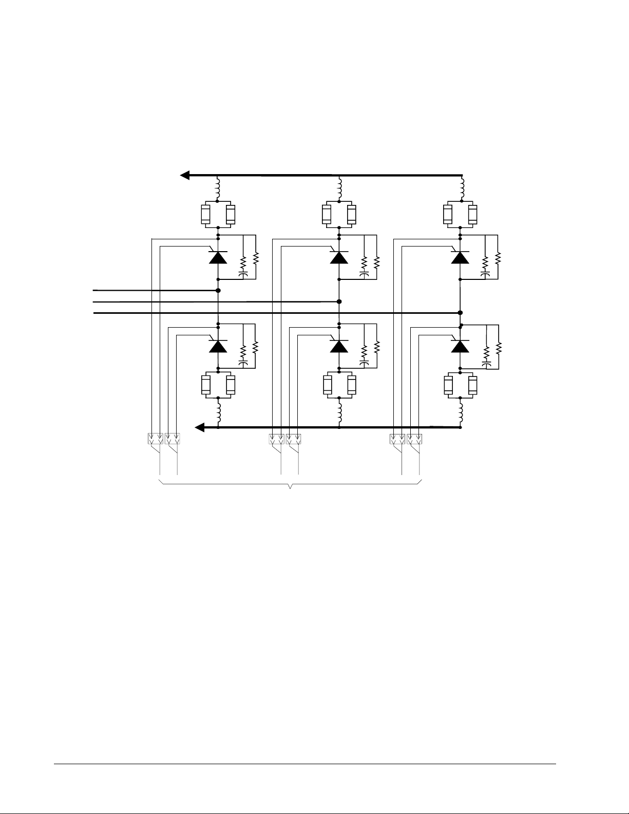
Bridge Rectifier
Each bridge rectifier is a 3-phase full-wave thyristor bridge The bridge has six SCRs
(thyristors) controlled by the Exciter Gate Pulse Amplifier board (EGPA) as shown
in Figure 2-3. Heat is dissipated through large aluminum cooling fins and forced air
flow from overhead fans.
Leg Reactors and Cell Snubbers
The commutating reactors are located in the ac legs feeding the SCRs, and the
snubbers are an RC circuit from the anode to the cathode of each SCR. The cell
snubbers, line-to-line snubbers and line reactors together perform the following
functions to prevent misoperation of the SCRs.
• Limit the rate of change of current through the SCRs and provide a current dump
to aid in starting conduction.
• Limit the rate of change in voltage across the cell and, during cell commutation,
limit the reverse voltage that occurs across the cell.
The SCR snubbers include PRV resistors to limit the peak reverse voltage. These
resistors can be removed if required.
Three-phase input power is fed to the bridge from the secondary of the PPT, either
directly or through an ac breaker or disconnect, and a line-to-line filter. With
inverting bridge designs, the bridge is capable of negative forcing voltage, which
provides fast response for load rejection and de-excitation. The dc current output of
the bridge is fed through a shunt, and on some designs a contactor (41A or both 41A
and 41B) to the generator field. The bridge design utilizes dc leg fuses to protect the
SCRs from overcurrrent.
EX2100 User’s Guide GEH-6632 Chapter 2 Functional Description
2-5
Page 26
••••
Current Shunt
EDCF provides dc current
and voltage feedback
To dc Breaker,
Shunt, and
Generator Field +
Ac power
Input
A dc shunt provides the bridge output current feedback signal. The mV output signal
is input to a differential amplifier on the EDCF board. The amplifier output voltage
controls the frequency of an oscillator, which generates a fiber-optic signal sent to
the control module. The bridge output voltage feedback signal is generated in a
similar way.
FU1A
SCR1
SCR4
FU4A FU4B FU5A
FU1B FU2A FU2B
SCR2
Snubber 1
Snubber 4
SCR5
Snubber 2
Snubber 5
FU5B
FU3A
SCR3
SCR6
FU6A
FU3B
Snubber 3
Snubber 6
FU6B
J1
The gate pulse amplifiers
directly control the SCRs.
Gen. Field -
Gate Driver Inputs from EGPA Board
Figure 2-3. Power Bridge
J2 J5
J3
J6J4
Gate Pulse Amplifiers (EGPA Board)
The EGPA board interfaces the control to the Power Bridge. EGPA takes the gate
commands from the ESEL board in the controller, and generates the gate firing
pulses for six SCRs (Silicon Controlled Rectifiers). It is also the interface for current
conduction feedback, and bridge airflow and temperature monitoring.
On a new exciter, an RTD is used to monitor the temperature and generate alarms
instead of the Klixon switches. Additional switches actuated by fan rotation monitor
cooling air flow across the bridge. On an exciter controls only retrofit, the exciter
may have provisions for accepting feedback from two thermal switches mounted
on the SCR heatsink assemblies. One thermal switch opens at the alarm level
(170 °F (76 °C)) and the other at the trip level (190 °F (87 °C)). These switches
are wired to the EGPA board and may require retrofitting into the existing bridge. If
either switch opens, a bridge overtemperature alarm is generated. If both switches
open, a fault and a trip are generated.
2-6
Chapter 2 Functional Description GEH-6632 EX2100 User’s Guide
Page 27

••••
Cooling Fan Assembly
The SCR bridge assembly is cooled with forced air. From two to six overhead fans
are used, depending on the bridge rating and redundancy requirements. The fans are
powered by single-phase 115 V ac supplied by the customer. In redundant
applications, a fan may be replaced while the exciter is running.
Main Dc Contactors. 41A or 41A/41B (Optional)
The main dc contactor (at the output of the power conversion module) provides a
disconnect between the power conversion module and the generator field. The
contactor picks up when the running mode is selected and no fault exists in the
excitation. The contactors are normally actuated using pilot relays on the EXTB
board driven by the controller. The auxiliary contacts from the contactor are routed
back through the EXTB board as feedback signals.
Free Wheeling Diode De-excitation
De-excitation, the dissipation of the field current after the dc contactor opens, can be
done with a free wheeling diode. This diode is connected from the generator field
negative lead (anode) to the positive lead (cathode). The reverse voltage causes
current to flow through the diode, and the field resistance causes the current decay.
EX2100 User’s Guide GEH-6632 Chapter 2 Functional Description
2-7
Page 28

••••
Auxiliary Cabinet
The auxiliary cabinet is located next to the power conversion cabinet and contains
modules to protect the generator and provide startup dc power. Modules for filtering
the incoming ac power, for de-excitation, shaft voltage suppression, and field
flashing are mounted in this cabinet.
Ac Line-to-Line Filters
Fuse protected line-to-line series RC filter circuits (snubbers) are provided to damp
the ac system to prevent voltage spikes at the completion of SCR commutation.
There are two styles of filters employed depending on the voltage. The 600 V filter
uses RC circuits and MOVs. The 1000 V filter uses the 600 V version with
additional RC circuits. Refer to Chapter 4 for details and connections.
De-excitation Module (EDEX)
During any shutdown, the energy stored in the generator field must be dissipated. In
a normal shutdown, a stop is initiated by an operator. The bridge is fired at retard
limit and sufficient time is allowed for the field to decay before the field contactors
are opened. During an abort stop (trip), the field contactors are opened immediately.
The stored field energy must be dissipated through some other means.
SCR De-excitation Module (EDEX)
For customers requiring a rapid de-excitation, an SCR de-excitation module is
provided. In the EDEX module, an SCR is fired to provide a conduction path
through the field discharge resistor (or inductor) for the field current to flow and
dissipate the field energy.
The de-excitation module has dual independent firing control circuits. Each is
activated by a parallel combination of auxiliary contacts representing the status of
the field contactor(s), bridge ac supply breaker, and exciter bridge operating state.
Any one of these paths can gate the de-excitation SCR which does not conduct
unless the field voltage is inverted. If neither firing control circuit can fire the SCR, it
is fired on overvoltage when the anode to gate voltage on the SCR exceeds the break
over voltage of the breakover diode string connected between the anode and gate.
De-excitation modules can be paralleled for larger excitation systems.
Thyrite
In systems that do not use the standard de-excitation module, a thyrite is connected
across the dc output buses of the thyristor bridge. This protects the thyristors from
high peak inverse voltages, which may occur as a result of abnormal generator
operation. These are typically only supplied on salient pole generators.
2-8
Chapter 2 Functional Description GEH-6632 EX2100 User’s Guide
Page 29

••••
Shaft Voltage Suppressor
The Shaft Voltage Suppressor
protects the shaft bearings.
The field ground detector
protects the generator shaft.
Excitation systems, which produce a dc voltage from ac through a solid state
rectification process, produce ripple and spike voltages at the exciter output. Due to
their rapid rise and decay times, these voltages are capacitively coupled from the
field winding to the rotor body. This creates a voltage on the shaft relative to ground.
Shaft voltage, if not effectively controlled, can be damaging to both journals and
bearings. The shaft voltage suppressor is a filter that conducts the high frequency
components of the induced voltages to ground. (This filter is shipped loose in some
cases, otherwise it is part of the lineup).
Field Flashing Module
The field flashing module is provided on generator terminal fed excitation systems. It
supplies initial exciter current and builds generator voltage, supplying approximately
10% - 15% of no-load field current from the station batteries during the startup
sequence. If large machines require ac field flashing, the ac power is supplied
through an isolation transformer. Both designs require customer supplied power.
Field Ground Detector (EXAM and EGDM)
The generator field winding is electrically isolated from ground. The existence of
one ground usually does not damage the rotor. However, the presence of two or
more grounds in the field winding path causes magnetic and thermal imbalances and
localized heating, which may damage the rotor forging or other metallic parts.
The function of the field ground detector is to detect a ground path from any exciter
component connected to and including the main field windings.
The Exciter Attenuator Module (EXAM) drives the electrical center of the field
winding with a low frequency ac voltage relative to ground. To detect the current
flow, the voltage across a sensing resistor is picked up by EXAM and measured by
the EGDM module. This signal is sent over a fiber-optic link to the controller where
it is monitored and alarmed. The EGDM boards (1 for simplex and 3 for redundant)
are mounted in the control power supply module located in the control cabinet.
High Voltage Interface – HVI
The HVI contains the ac and dc bus, plus the line filter fuses. It also contains two
terminal boards providing bridge feedback to the control and the EXAM board. The
EACF board accepts incoming PPT ac voltage and air core CT current signals. It has
transformers to isolate the voltages and produce low level signals. The EDCF board
measures the bridge dc current and voltage, and sends it over fiber-optics to the
control.
EX2100 User’s Guide GEH-6632 Chapter 2 Functional Description
2-9
Page 30
••••
Control Cabinet
The control cabinet contains the keypad control rack, control power distribution
module and supplies, and I/O terminal boards.
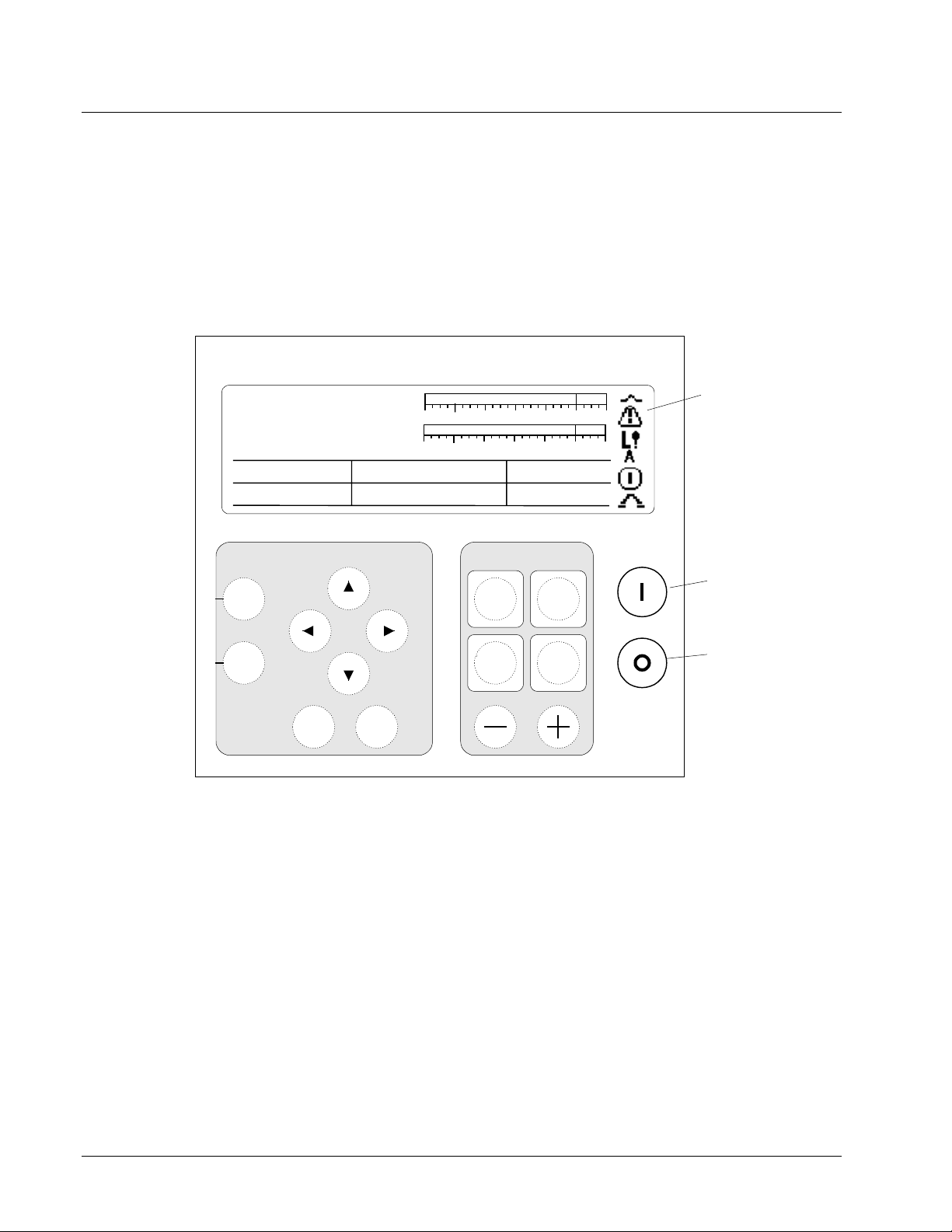
Diagnostic Interface (Keypad)
A second keypad is provided
for redundant controls.
g
FVR Feedback
FldCurrAmps
Vmag
Freq_Hz
60.00
Navigation
Status
Menu
The keypad is a local operator interface that is mounted on the control cabinet door.
Refer to Figure 2-4 for a view of the keypad and a summary of the operator and
maintenance functions available. Chapter 5 describes the keypad in detail.
EX2100 Excitation Control
Exciter Health
0.0 Volts
0.00 Amps
0% 150%
-30%
0% 150%
-30%
Imag
0.000.00
Balance Meter Vars
0.00
Exciter Control
Reset
Faults
Command
Menu
Voltage Level
EnterEscape
Watts
0.00
0.00
100%
100%
On
Auto
Man
Off
& State Icons
Run (Green)
Stop (Red)
Display:
Status
screens provide analog and digital
representation of exciter functions and values.
Menu
screens provide text-based access to
parameters, wizards, and faults.
Pushbuttons:
Organized into functional groups:
Navigation
Exciter Control
Run
buttons for using the menu
buttons
and
Stop
buttons
Figure 2-4. Diagnostic Interface – Keypad
Start/stop commands, regulator transfer commands, and regulator activation
commands can be issued from the keypad. The keypad also includes meter displays
indicating system conditions such as generator MW and MVARs, field current and
voltage, and regulator balance. Diagnostic displays such as the alarm history display
provide system information for maintenance and troubleshooting.
2-10
Chapter 2 Functional Description GEH-6632 EX2100 User’s Guide
Page 31

••••
Control Module
The control module is a VME-style rack with boards cable connected to the I/O
terminal boards. This rack is divided into three independently powered sections for
the M1, M2, and C controllers. Each controller consists of control and I/O processor
boards. If the rack contains only the M1 controller then it is a simplex control
system; if the rack contains all three controllers then it is a redundant control system.
The control and I/O processor boards are as follows:
• Microprocessor-based Application Control Layer Module (ACLA) controller,
with LAN Ethernet port
• Microprocessor-based Digital Signal Processor (DSPX) controller
• Exciter ISBus Board (EISB), with fiber-optic communication with the bridge
feedback board
• Exciter Main I/O Board (EMIO), with control of pilot relays and gating
commands to the ESEL board
• Exciter Selector Board (ESEL), with gate pulse distribution from the active
controller to the EGPA.
EX2100 User’s Guide GEH-6632 Chapter 2 Functional Description
2-11
Page 32
••••
Ethernet Data Highway to
Mark VI, LCI, and HMI
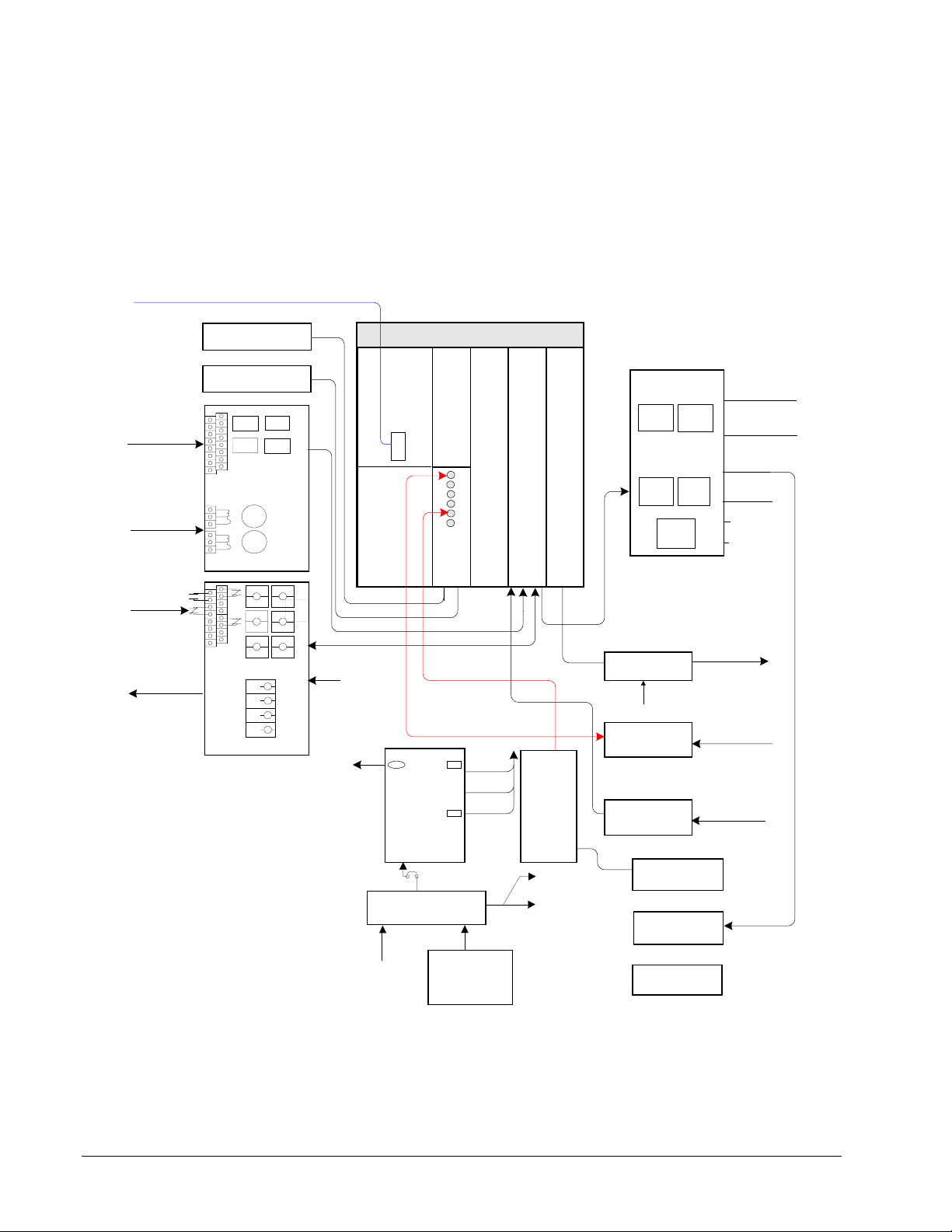
Simplex Control System
The interconnections between the simplex control and the terminal boards,
generator protection modules, and power supply are shown in Figure 2-5. Only one
EPSM power supply is used but this can have both ac and dc supplies for increased
reliability.
3-phase
Voltage
Sensing
3-phase
Current
Sensing
Contact
Inputs
Contact
Outputs
Keypad
Computer (Tool)
PT
PTPTPT
CT
CT
EPCT
TRIP
TRIP
TRIPTRIP
86
86
8686
2nd
2nd
2nd2nd
TRIP
TRIP
TRIPTRIP
ECTB
70 Vdc
70 Vdc
Control Module M1
ACLA
DSPXEISB
Fiber-optic Feedback
EPSM
Power
Supply
5 Vdc
15 Vdc
24 Vdc
EMIO Master I/0
EGDM
Field
Ground
Detector
ESEL
41
41
To Flashing
panel
41 Device
Deexcitation
Crowbar
125 Vdc
53A
pilot
53B
pilot
EXTB
close
trip
De-ex
pilot
Gate Pulse Amplifier
EGPA
125Vdc
To SCRs
Field Current
EDCF
& Voltage
PPT and air
core CT
EACF
ac feedbacks
70 V dc
EXAM
Deexcitation
EDEX
Optional:
Crowbar
125 V dc
Battery
EPDM
Rectified ac
GPA power
Coil Power
125 Vdc
Option:
DACA
Figure 2-5. Simplex Control and Cabling to Terminal Boards
2-12
Chapter 2 Functional Description GEH-6632 EX2100 User’s Guide
Page 33

••••
Redundant Control System
A redundant control system has three controllers and three redundant power supplies,
one for each controller. The power supply rack also holds three ground detector
modules. Figure 2-6 shows three EDCF boards, and there can be three EPCT boards,
if required.
Up to two Ethernet cables are connected to the ACLA controllers (one to M1 and
one to M2) for redundant communication with the turbine control and HMIs. Two
keypads are shown connected to M1 and M2. Both keypads have access to the
information in controller C.
Ethernet Data Highway to Turbine Control and HMI
PT
PTPTPT
Fan-out
circuits
CT
CT
EPCT
TRIP
TRIP
TRIPTRIP
86
86
8686
2nd
2nd
2nd2nd
TRIP
TRIP
TRIPTRIP
ECTB
70V
Keypad
Tool
70V
PN24V
EPSM
Power
Supply
ACLA
P24V
DSPX
EISB
E
G
D
M
EMIO Master I/0
70V
PN24V
EPSM
Power
Supply
EBKP
Backplane
M2M1
ESEL
ESEL
EMIO Master I/0
Bridge 1
Bridge 2
Bridge 3
Bridge 4
Bridge 5
Bridge 6
P24V
E
G
D
M
DSPX
EISB
70V
PN24V
EPSM
Power
Supply
P24V
Keypad
ACLA
DSPX
EISB
E
G
D
M
C
EMIO Master I/O
Fiber-optic Field
EXTB
70V
70V
Gate Pulse Amplifiers
V & I feedback
PPT and air core CT
(AC) Feedbacks
53A
41
pilot
close
53A
close
pilot
53A
pilot41close
41
53B
trip
pilot
53B
trip
pilot
53B
trip
pilot
EACF
41
41
41
EGPA
EGPA
De-ex
pilot
Option: Field Breaker
125Vdc
125Vdc
EDCF
EDCF
EDCF
To Flashi ng
panel
41 Device
Deexcitation
Crowbar
-125Vdc
EDEX
EPBP
back
plane
Field
Ground
Detector
EGDM
EPDM
125 V dc
Battery
Option:
DACA
Rectified ac
125 Vdc
Coil Power
GPA power
De-excitation
EXAM
Attenuator
Optional:
Crowbar
Figure 2-6. Redundant Control System Cabling
EX2100 User’s Guide GEH-6632 Chapter 2 Functional Description
2-13
Page 34
••••
Controller C
Controller C is only used with redundant systems. It is mounted in the control rack
and is physically similar to the M1 and M2 controllers, however, C is not responsible
for bridge firing and therefore does not contain an ESEL, or ACLA board.
Controller C receives the same feedback voltage and current inputs as the other
controllers and contains similar software. Its purpose is to monitor the active and
backup controllers (M1 or M2) and initiate appropriate protective responses in the
event the system conditions exceed the defined regulation boundaries. Input and
output signal voting takes place in all three controllers, which are linked in a Triple
Modular Redundant (TMR) controller configuration.
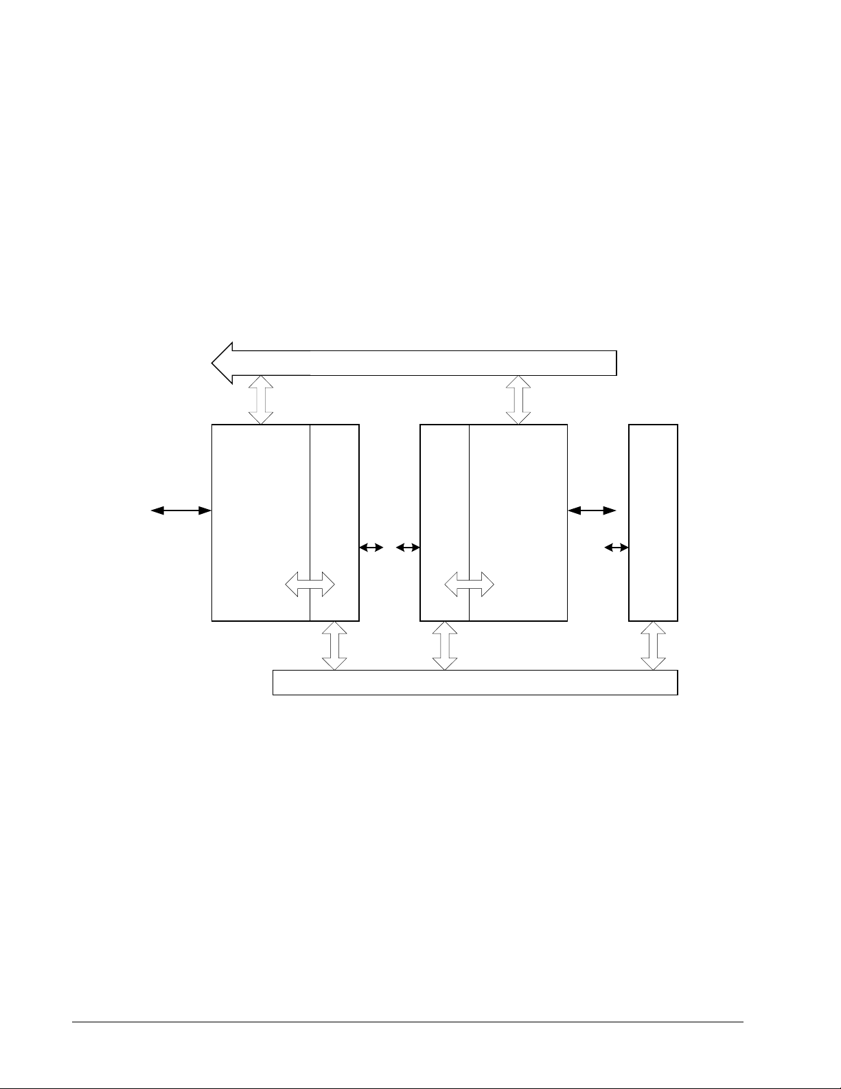
Each controller contains up to six boards, interconnected through the backplane as
shown in the simplified diagram of Figure 2-7.
To plant controls
Serial
Modbus
Communication
across backplane
Ethernet Data Highway (EGD, Modbus)
ACLA
M1
DPM DPM
Figure 2-7. Communication between Redundant Control Boards
DSPX
M1
DSPX
M2
I/O I/O I/O
ISBus
ACLA
M2
Serial
Modbus
DSPX
C
Control Power Supplies
Redundant supplies provide
high reliability.
2-14
Chapter 2 Functional Description GEH-6632 EX2100 User’s Guide
Power for the controls come from the Exciter Power Distribution Module (EPDM).
This is supplied by a 125 V dc source and one or two 115 V ac sources. The ac
source is passed through an ac/dc converter (DACA) as shown in Figure 2-8. The
resulting 125 V dc is diode coupled with the other dc sources to create a dc bus that
feeds the control modules and gate pulse amplifier boards. Fused outputs from the
EPDM feed power to the EGPA boards, EXTB, and the Exciter Power Backplane
(EPBP). Each output has an LED indication and an on/off isolation switch.
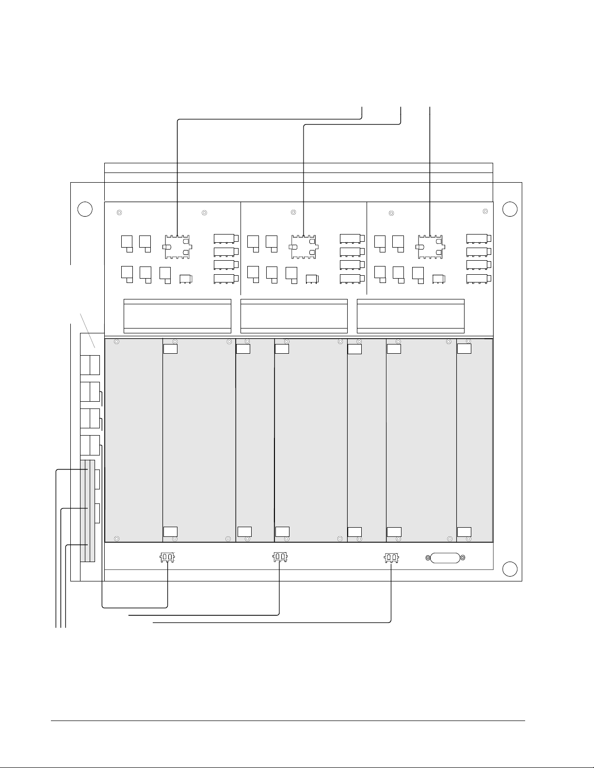
The EPDM mounts on the left side of the Exciter Power Supply rack. Up to three
Exciter Power Supply Modules (EPSM) mount in the EPBP backplane and provide
logic level power to the controller(s). The EPSMs are fed by 125 V dc from the
EPDM, and generate supply voltages of +5 V dc, ±15 V dc, and +24 V dc. In
Page 35
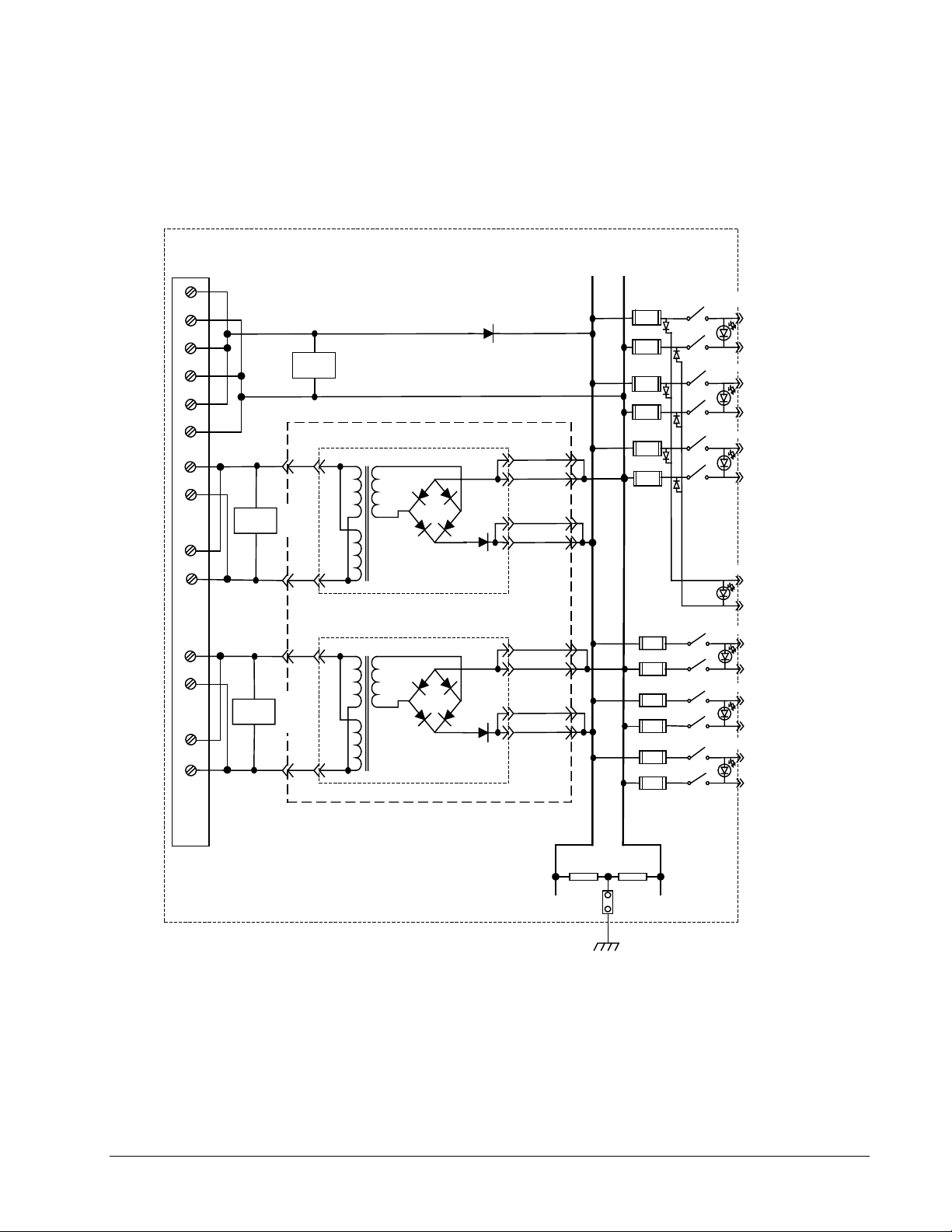
••••
addition there is an isolated 70 V dc output for use by EXTB and ECTB for contact
wetting.
Up to three ground detection modules (EGDM) are also mounted in the EPBP, as
shown in Figure 2-9. These communicate with the EXAM module, which is located
in the auxiliary cabinet.
Exciter Power Distribution Module (EPDM)
TB1
1
2
3
4
5
6
15
16
17
18
P125
125
V dc
N125
AC1 Hot
Filter
AC1 Neu.
Filter
115 Vac DACA #1
JDACA1
1
1
115
Vac
3
3
7
10
9
12
JDACA1
P125V
7
10
9
12
N125V
FU1
3.15A
FU2
3.15A
FU3
3.15A
FU4
3.15A
FU5
3.15A
FU6
3.15A
SW1
SW2
SW3
J8A
1
DS1
G
DS2
G
DS3
G
DS4
G
J8B
J8C
J9
To
2
EGPA1
1
To
EGPA2
2
1
To
2
EGPA3
1
To
3
EXTB
21
22
23
24
AC2 Hot
Filter
AC2 Neu.
1
115
115 Vac DACA #2
JDACA2
1
7
10
JDACA2
9
Vac
33
12
BJS jumper is supplied for
isolation of ground reference
on systems with external
reference
Figure 2-8. Exciter Power Distribution Module
7
10
9
12
R1 R2
BJS
Chassis
Ground
FU7
8A
FU8
8A
FU9
8A
FU10
8A
FU11
8A
FU12
8A
SW4
SW5
SW6
DS5
G
DS6
G
DS7
G
J1M1
J1M2
J1C
2
To
1
EPSM1
2
To
EPSM2
1
2
To
EPSM3
1
EX2100 User’s Guide GEH-6632 Chapter 2 Functional Description
2-15
Page 36
••••
Power to Exciter Backplane
EBKP (Control Rack)
To M1 To M2 To C
Exciter Power
Distribution
Module
EPDM
J1M2J1C
J1M1
EDEX EDCF
EDEX
CROWBAR
Blank
plate
M2
CONTROL
J602
MEDIA
FAN
CONV
EDEX
EETB
ECTB
EXTB
EGDM
M1
CONTROL
J602
FAN
MEDIA
CONV
EDEX
EETB
ECTB
EXTB
EDEX EDCF
EDEX
CROWBAR
EGDM
Fan Fan Fan
EPSM
Power
Supply
M1
EGDM
Ground
Detector
M1
EPSM
Power
Supply
M2
EDEX EDCF
EDEX
CROWBAR
EGDM
Ground
Detector
M2
EGDM
C
CONTROL
J602
FAN
EPSM
Power
Supply
C
MEDIA
CONV
EDEX
EETB
ECTB
EXTB
EGDM
Ground
Detector
C
To J1M1
J1_M1
To J1M2
J1_M2
To J1C
J1_C
J2C
GROUND
DETECT
125 V dc
115 V ac
Supplies
Figure 2-9. Exciter Power Backplane (EPBP) with EPDM, Power Supplies & Ground
Detector Modules
2-16
Chapter 2 Functional Description GEH-6632 EX2100 User’s Guide
Page 37

••••
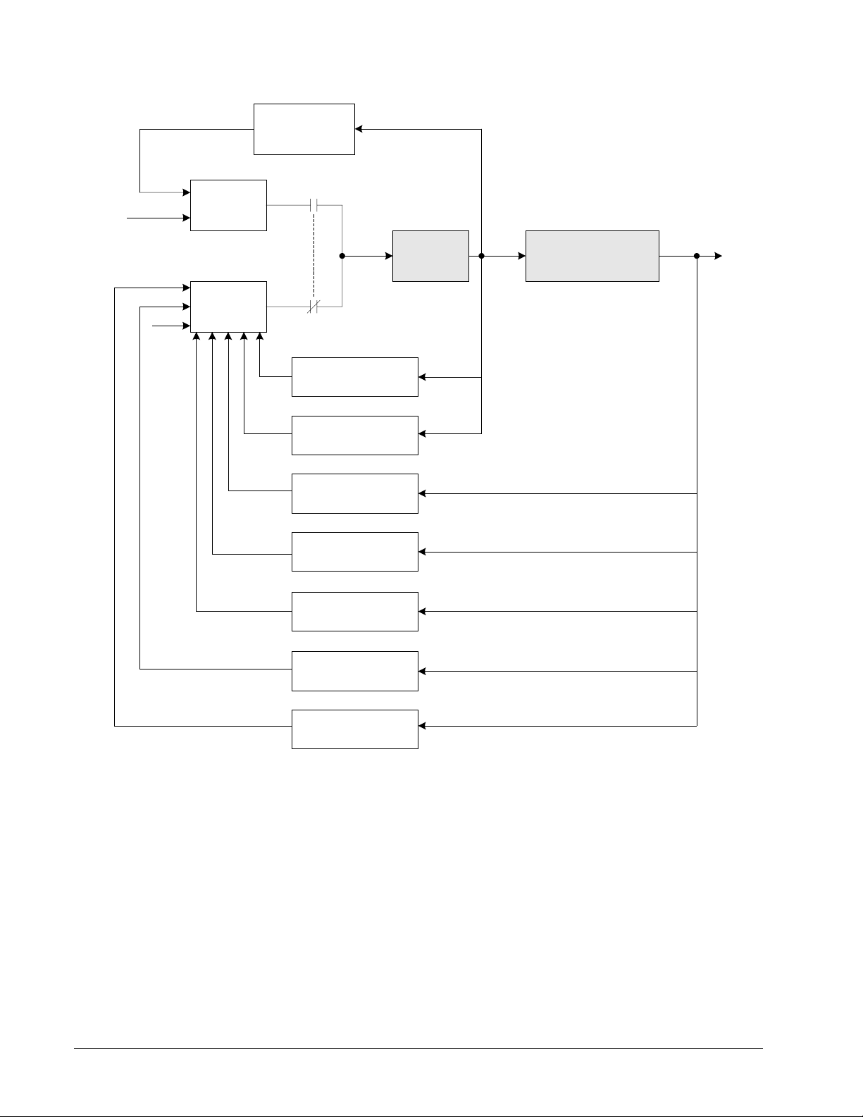
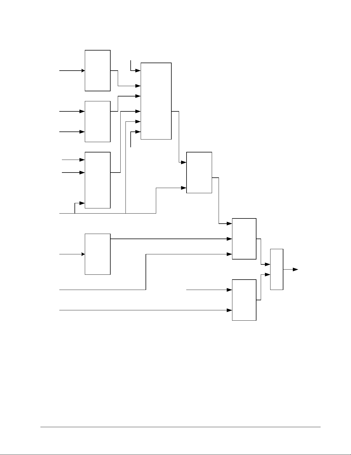
Exciter Software
The exciter software is configured and loaded from the toolbox, and resides in the
controllers. The software is represented on the toolbox screen by control blocks
linked together to show the signal flow. Figure 2-10 is a simplified overview of the
exciter control system displaying the main control functions. Both the generator field
and stator currents and voltages are measured and input to the control system. In
normal operation the ac regulator is selected. Figure 2-11 is the simplified software
block diagram displaying the main control blocks.
The generator voltages and currents from the PTs and CTs are wired to the EPCT
board, which acts as a signal conditioner to isolate and scale the signals. The
conditioned signals are then fed to the controller. Software conversion algorithms
use these signals to calculate system variables for use by the regulator, limiter, and
protection functions. The outputs from these software calculations include the
following:
• Generator voltage magnitude and generator frequency derived from the PTs
• The magnitude of generator current derived from the CTs
• Generator power, P
• Generator reactive volt amperes (VARs), Q
• Change in rotor speed calculated from the integral of accelerating power that is
normally used as the input to the optional Power System Stabilizer (PSS)
• Generator active and reactive current
• Magnitude of generator flux (VHz)
• Line voltage derived from the PTs
• Line frequency derived from line PTs
• Phase angle correlation between the generator and line, derived from generator
and line PTs
EX2100 User’s Guide GEH-6632 Chapter 2 Functional Description
2-17
Page 38
••••
DC Voltage
adjust
AC
Voltage
adjust
DC
Regulator
AC
Regulator
Voltage/Current
Sensing
Exciter System
Stabilizer Circuits
Over-excitation
Limiter
Under-excitation
Limiter
Exciter
Bridge
Generator
V/Hz Limiter &
Protection
VAR/Power Factor
Control
Voltage Sensing &
Load Compensation
Power System
Stabilizer
Figure 2-10. Control Scheme
2-18
Chapter 2 Functional Description GEH-6632 EX2100 User’s Guide
Page 39
••••
External
Raise/
Lower
AUTO
REF
Reactive
Current
Setpoint
Watts
Slip
Watts
VARs
Generator
Terminal
Voltage
(VMAG)
External
Raise/
Lower
Field Volts from Bridge Output
PSS
Power
System
Stabilizer
UEL
Under
Excitation
Limit
MANUAL
REF
EXASP
Exciter AVR
Setpoint.
V/Hz Limit;
Reactive
Current
Compen-
sation.
Frequency
VMAG
VMAG
Field Voltage Regulator Setpoint
AVR
Setpoint
and
Tracking
Automatic
Voltage
Regulator
FCR Setpoint
(User Input)
AVR
FVR
Track
Value
Setpoint
Voltage
Regulator
FVR
Field
FCR
Min.
Firing
Commd
to
Bridge
Field
Field Current from Bridge DC Shunt
Current
Regulator
Figure 2-11. Software Block Diagram
The output of the control software is the firing command, which is sent to the bridge
to generate the field current. The individual function blocks are discussed in the
following sections.
EX2100 User’s Guide GEH-6632 Chapter 2 Functional Description
2-19
Page 40

••••
Auto Reference – AUTO REF
The AUTOREF block generates an auto (or Auto Control (AC)) setpoint for the
Automatic Voltage Regulator (AVR) based on user-supplied parameters and
conditions. Raise/lower inputs to AUTO REF come in from the other devices on the
Data Highway such as the turbine control or HMI. A variable rate integrator
generates the output setpoint within preset limits. The setpoint is combined with
other auxiliary stabilizing and protective signals in the EXASP block to form the
reference to the AVR block.
AVR Setpoint – EXASP
The EXASP block combines a number of functions to produce the setpoint
(reference input) to the AVR, and the AVR tracking value. The EXASP inputs are as
follows:
• Stabilizing signal from the PSS block
• Output from the AUTOREF block
• External test signal
• Protective signal generated by the UEL block
• Reactive current input (feedback)
• Voltage magnitude input (feedback)
• Frequency input (feedback)
Generator terminal voltage is
controlled by the AVR.
The outputs to the AVR block are the AVR setpoint and tracking value.
Automatic Voltage Regulator – AVR
The AVR block maintains the generator terminal voltage. The setpoint (reference)
comes from the EXASP block, and the feedback is the generator voltage. The error
value is input to a proportional plus integral (PI) regulator with integrator windup
protection, which produces an output signal. Figure 2-12 shows the block diagram.
When the AVR is enabled, the AVR output is passed through directly from the track
input to the output of the Field Voltage Regulator (FVR).
2-20
Chapter 2 Functional Description GEH-6632 EX2100 User’s Guide
Page 41

••••
Preset Condition
Preset Not True
SRQ
Preset State True
Q
Gain
Scaling
AVR
Setpoint
Status of
Regulators
Enable
1
+
Σ
-
Generator
Voltage
0.05
Error
a
b
windup
a>b?
Proportional Gain
Anti-
Integral Gain
Integrator
Tracking Input
+
Σ
-
Preset
Value
+
Σ
-
Output Value
Tracking
Tracking
Gain r/s
Control
Q
Preset
State
Software
Jumper 0
Integration
Output
1
s
+
Software
Jumper 1
Positive
Limit
+
Σ
Output
Negative
Limit
AVR
Status
Figure 2-12. Automatic Voltage Regulator Block
Manual Reference – MANUAL REF
The MANUAL REF block generates a manual setpoint for the FVR or FCR based on
user-supplied parameters and conditions. Raise/Lower inputs to MANUAL REF
come in from other control devices on the Data Highway such as the turbine control
or HMI.
Field Voltage and Current Regulators - FVR & FCR
The Field Voltage Regulator (FVR) is the typical manual regulator supplied on most
applications and uses the generator field voltage as the feedback input. While FVR
does permit the current to vary as a function of the field resistance, the FVR makes
the manual regulator completely independent from the over excitation limiter. FVR
uses the voltage from the generator field as feedback, with a setpoint from the
MANUAL REF block. A PI regulator with integral windup protection generates the
output. During operation in AVR mode, the output of the AVR is passed directly to
the FVR output with no signal conditioning. On units that operate with an inner field
EX2100 User’s Guide GEH-6632 Chapter 2 Functional Description
2-21
Page 42

••••
voltage regulator loop such as compound exciters and some high ceiling exciters, the
FVR uses a setpoint from either the AVR or the MANUAL REF block, and is
always operational whether in manual or automatic operation.
The Field Current Regulator (FCR) is a special application of the manual regulator
and uses the generator field current as the feedback input. The current setpoint is
generally switched between a high level and lower level to provide transient forcing
capability as well as steady state operation within the capability of the generator.
Generally the setpoint is larger than expected field currents and the integral preset is
operational. The FCR output is held at positive ceiling until enable becomes true
which allows the output to follow the P+I regulator. The bridge firing command is
the smaller of the FVR and FCR outputs. While it does regulate constant field
current over varying field temperature, FCR is not the standard manual regulator.
Under Excitation Limiter – UEL
The UEL block is an auxiliary control to limit the automatic voltage regulator
demand for underexcited reactive current (or reactive power). UEL prevents
reduction of the generator excitation to a level where the small-signal (steady state)
stability limit, or the stator core end-region heating limit is exceeded. Performance is
specified by identifying the region of limiter action on the generator capability curve.
There is both a setpoint section and regulator section of the UEL. The two key inputs
are generator terminal voltage and real power.
Power System Stabilizer – PSS
The PSS block provides an additional input to the automatic regulator to improve
power system dynamic performance. A number of different quantities may be used
as inputs to the PSS, such as shaft speed, frequency, synchronous machine electrical
power, accelerating power, or some combination of the above. The PSS used with
the exciter is multi-input using a combination of synchronous machine electrical
power and internal frequency (which approximates rotor speed) to arrive at a signal
proportional to rotor speed. This comes from the integral of accelerating power, but
with shaft torsional signals greatly attenuated. The input signal is derived entirely
from generator terminal quantities without the need for shaft speed transducers. No
additional external hardware is required.
2-22
Chapter 2 Functional Description GEH-6632 EX2100 User’s Guide
Page 43

••••
Operator Interface
The HMI contains exciter and
turbine graphic displays.
An HMI can be mounted in a
control console or on a
tabletop.
Redundant cable operation is
optional and, if supplied,
operation continues even if
one cable is faulted.
Operator and engineering work stations such as the HMI (Human Machine Interface)
and the toolbox communicate with the exciter. This allows operator monitoring and
control of the exciter, and engineering access to system diagnostics and control
block configuration
Turbine Control HMI
On turbine generator sets that include Mark VI turbine controls, the exciter shares
the HMI. The HMI is Windows NT
software and communication drivers for the data highways. From the HMI, the
operator can initiate commands and view real-time data and alarms on the
CIMPLICITY graphic displays. An HMI can be configured as a server or viewer,
and can contain tools and utility programs.
The Unit Data Highway (UDH) connects the exciter with the HMI or HMI/Data
Server. The network is 10BaseT Ethernet, and uses separately powered network
switches. For longer runs, fiber-optic cables can be used.
®
based with CIMPLICITY operator display
Control System Toolbox (toolbox)
The toolbox is used to configure and maintain the exciter. Control blocks and
diagrams can be modified by configuration and loaded into the control. With the
exciter online, real-time data is available on the toolbox screen, including control
system diagnostics for troubleshooting. The toolbox software runs on an HMI server
or a separate PC on the UDH. Direct connection to the controller DSPX board is also
possible through the Tool port on the control rack backplane.
EX2100 User’s Guide GEH-6632 Chapter 2 Functional Description
2-23
Page 44

••••
Notes
2-24
Chapter 2 Functional Description GEH-6632 EX2100 User’s Guide
Page 45

••••
Chapter 3 Printed Wiring Boards Overview
Introduction
This chapter describes the EX2100 printed wiring boards and their operation. These
boards fall into four functional groups; control rack boards including controller
boards and I/O processors, I/O terminal boards, bridge control and protection
modules, and power supply boards. This chapter is organized as follows:
Section Page
Control Boards......................................................................................................... 3-2
EBKP Backplane .............................................................................................. 3-2
DSPX Board ..................................................................................................... 3-2
ACLA Board..................................................................................................... 3-4
EISB Board....................................................................................................... 3-4
EMIO Board ..................................................................................................... 3-4
ESEL Board...................................................................................................... 3-4
I/O Terminal Boards ................................................................................................ 3-5
EPCT Board...................................................................................................... 3-5
ECTB Board ..................................................................................................... 3-5
EXTB Board..................................................................................................... 3-5
EDCF Board ..................................................................................................... 3-6
EACF Board ..................................................................................................... 3-6
Bridge and Protection Boards and Modules............................................................. 3-7
EGPA Board..................................................................................................... 3-7
EXCS Board ..................................................................................................... 3-7
EDEX Board..................................................................................................... 3-7
EGDM Module ................................................................................................. 3-7
EXAM Module ................................................................................................. 3-8
Power Supply Boards............................................................................................... 3-9
EPDM Module.................................................................................................. 3-9
EPBP Backplane............................................................................................... 3-9
EPSM Module .................................................................................................. 3-9
DACA – Ac to Dc Converter.......................................................................... 3-10
Related Board Publications.................................................................................... 3-11
EX2100 User’s Guide GEH-6632 Chapter 3 Printed Wiring Boards Overview
3-1
Page 46

••••
Control Boards
The control boards are located in the control module. This module consists of the
exciter backplane (EBKP) and the metal chassis that holds the boards (refer to Figure
3-1). The control boards are as follows:
• IS200DSPX Digital Signal Processor control board (DSPX)
• IS215ACLA Application Control Layer Module (ACLA)
• IS200EISB Exciter ISBus Board (EISB)
• IS200EMIO Exciter Main I/O board (EMIO)
• IS200ESEL Exciter Selector board (ESEL)
EBKP Backplane
The EBKP provides the backplane for the control boards and the connectors for the
I/O terminal board cables. EBKP has three sections for controllers M1, M2, and C.
Each section has its own independent power supply. Controllers M1 and M2 have
the ACLA, DSPX, EISB, EMIO, and ESEL boards. Section C only has the DSPX,
EISB, and EMIO. Two overhead fans cool the controllers.
The upper part of the backplane contains DIN connectors for the plug-in control
boards. The lower part of the backplane contains D-SUB connectors for I/O interface
cables, and circular DIN connectors for keypad interface cables, power supply plugs,
and test rings. Labels on the connectors in Figure 3-1 refer to the boards and devices
to which the cables are connected. For more information refer to Chapter 4 and GEI-
100460.
The DSPX performs most of
the I/O interface and inner
loop bridge control and
protection functions
DSPX Board
The DSPX board is the main controller and shares control responsibility with the
ACLA. It is a single-slot, 3U high module located in the control rack next to the
ACLA. It provides functions including the bridge firing circuit control, I/O
processing, and inner loop regulation as follows:
• Field Voltage Regulator (FVR)
• Field Current Regulator (FCR)
• SCR gating signals to the ESEL board
• Start-stop function
• Field flashing control
• Alarms and trip logic
• Generator instrumentation processing
• Generator simulator
For more information refer to Chapter 4 and GEI-100267.
3-2
Chapter 3 Printed Wiring Boards Overview GEH-6632 EX2100 User’s Guide
Page 47

••••
Fan Fan
RST
OK
ACTIVE
ENET
FLASH
S
T
A
T
U
S
1
2
DSPX
EISB EISB
EMIO ESEL ESEL EMIO
J304 J305 J306 J307 J308 J309
E
Keypad
M1
Tool M1 Tool M2
E
P
G
C
P
T
A
1
E
E
P
G
C
P
T
A
2
DSPX ACLAACLA
Keypad
M2
1
RST
OK
ACTIVE
ENET
FLASH
2
S
T
A
T
U
S
DSPX
Keypad
C
Tool C
EMIOEISB
J315J314
E
P
C
T
J405J404 J406 J407 J408 J409
E
Test Rings M1 Test Rings M2 Test Rings C
E
C
T
B
E
G
P
A
3
E
G
C
P
T
A
B
4
J414 J415
E
C
T
B
M1-Fan Pwr M2-Fan Pwr C-Fan Pwr
M1
Power
J502
21
43
J602
10
1
E
E
A
C
X
F
T
1
2
3
IS200EBKPG1AAA
B
J509J508J507J506J505J504
E
G
P
A
5
E
E
X
G
T
P
B
A
6
Power
J510
21
E
43
A
C
F
J610 J612
10
M2
1
J512
21
43
1
2
1
10
2
C
3
1
3
Power
J515J514
E
E
A
X
C
F
T
B
Figure 3-1. Control Module
EX2100 User’s Guide GEH-6632 Chapter 3 Printed Wiring Boards Overview
3-3
Page 48

••••
ACLA Board
ACLA handles network
communications and outer
loop functions.
EISB manages all the fiberoptic communication in the
cabinets.
The ACLA board is a double-slot, 3U high module located next to the DSPX. ACLA
provides Ethernet communications with the turbine control, LCI, and HMI, and runs
outer loop control functions including the following:
• Automatic Voltage Regulator (AVR)
• Power System Stabilizer (PSS)
• Under Excitation Limit control (UEL)
• VAR/power factor regulator (VAR/PF)
For more information refer to Chapter 4 and GEI-100434.
EISB Board
The Exciter ISBus Board (EISB) is a special communication interface board for the
M1, M2, and C control modules. ISBus is a proprietary, high-speed communication
bus used in many GE systems. The EISB is used to provide communication among
the 3 DSPSs in M1, M2, and C. EISB receives and transmits fiber-optic feedback
signals through the backplane connector. It transmits them over the control
backplane to the DSPX controller and also communicates between the DSPX and the
tool and keypad ports using RS-232C. EISB is a single-slot, 3U high module that is
located in the control rack under the DSPX. From six fiber-optic connectors on the
front panel it accepts current and voltage signals from the generator field (and from
the exciter if required) using EDCF boards, and receives and transmits signals to the
Ground Detection Module (EGDM). For more information refer to Chapter 4 and
GEI-100454.
EMIO Board
The EMIO is a single slot, double height VME style board, that manages the I/O
from the EPCT, ECTB, EACF, and EXTB terminal boards. The I/O include PT and
CT signals, contact inputs, output relay drivers, and pilot trip relay drivers. It also
sends logic level gate pulse signals over the backplane to the ESEL board, which
sends them to EGPA in the power conversion cabinet. For more information refer to
Chapter 4 and GEI-100453.
ESEL Board
The Exciter Selector board receives six logic level gate pulse signals from its
corresponding EMIO. These pulse signals drive up to six sets of cables which are
distributed to the exciter gate pulse amplifier (EGPA) boards. The EGPA boards are
mounted in the power conversion cabinet. If there are redundant controls, two ESEL
are used, one driven by M1 and the other by M2. The active ESEL, selected by
controller C, sends the necessary control signals to the EGPA boards.
Three groups of ESEL boards are available supporting increasing redundancy levels;
ESELH1 contains a single bridge driver, ESELH2 contains three bridge drivers, and
ESELH3 contains six bridge drivers. For more information refer to Chapter 4 and
GEI-100456.
3-4
Chapter 3 Printed Wiring Boards Overview GEH-6632 EX2100 User’s Guide
Page 49

••••
I/O Terminal Boards
y
y
The exciter terminal boards are as follows:
• IS200EPCT Exciter PT/CT board (EPCT)
• IS200ECTB Exciter Contact Terminal Board (ECTB)
• IS200EXTB Exciter Terminal Board (EXTB)
• IS200EDCF Exciter Dc Feedback board (EDCF)
• IS200EACF Exciter Ac Feedback board (EACF)
EPCT Board
EPCT receives and conditions
generator PT and CT
feedbacks.
EXTB handles field flashing
and protection functions.
The EPCT contains isolation transformers for critical generator voltage and current
measurements. Two three-phase generator PT voltage inputs are input to EPCT. Two
generator CT current inputs, with current levels of 1 A or 5 A, are input. In addition,
one analog input, which can be either 0-10 V or 4-20 mA, is brought into EPCT. All
the signals are interfaced to the EMIO board. For more information refer to Chapter
4 and GEI-100459.
ECTB Board
The ECTB board supports excitation contact outputs and contact inputs. There are
two versions; the ECTBG1 board which is only used in the redundant mode, and the
ECTBG2 board which is only used in the simplex mode. Each board contains two
trip contact outputs driving a customer lockout, and four general purpose Form-C
relay contact outputs, controlled by the EMIO board. Six auxiliary contact inputs are
powered (wetted) with 70 V dc by ECTB. Also, the 52G and 86 G contact inputs are
powered and monitored by ECTB. In the redundant case, power comes from the M1
and M2 power supplies. For more information refer to Chapter 4 and GEI-100457.
EXTB Board
The EXTB board supports pilot relay contact outputs, contact inputs, and signal
conditioning circuits. EXTB cables to the EMIO board through the EBKP
backplane.
Pilot relays for the breaker/contactor close 41, and flashing contactors 53A, and 53B
are located on the board, plus pilot relays for the trip relay 41T and the de-excitation
relay KDEP. Crowbar status signals and de-excitation status signals from the EDEX
board are conditioned on EXTB and sent to EMIO. Three contact inputs from 41,
53A, and 53B are powered (wetted) by 70 V dc on EXTB. Power for the contacts is
from the M1 and M2 power supplies (redundantly), and the resulting status signals
are sent to EMIO in the control rack. Different groups of EXTB are available for
controlling either a field breaker or a contactor in the field circuit. These groups are
defined in Table 3-1. For more information refer to GEI-100458.
Table 3-1. EXTB Board Groups
Trip Rela
Type of Redundancy Board Control Mode
Redundant control EXTB G1 Contactor Mode No Yes
Redundant control EXTB G3 Breaker Mode Yes Yes
Simplex control EXTB G2 Contactor Mode No Yes
Simplex control EXTB G4 Breaker Mode Yes Yes
EX2100 User’s Guide GEH-6632 Chapter 3 Printed Wiring Boards Overview
41T used
Close Rela
41 used
3-5
Page 50

••••
EDCF Board
EDCF handles bridge dc
voltage and current feedback.
EACF handles bridge ac
voltage and current feedback.
The EDCF board measures field current and field voltage at the SCR bridge, and
interfaces to the EISB board in the control panel over a high-speed fiber-optic link.
The fiber-optics provides voltage isolation between the two boards, and high noise
immunity. Field current is measured using a shunt in the dc field circuit. The field
voltage feedback circuit provides seven selector settings to scale down the bridge
voltage, depending on the type of bridge application. For more information refer to
Chapter 4 and GEI-100464.
EACF Board
The EACF board measures the exciter PPT ac supply voltage and current. The
EACF terminal board contains transformers for a 3-phase voltage measurement, and
terminals for two Flux/Air core coils. The outputs of the voltage and current circuits
are fanned out to three DB9 connectors for cables to controllers M1, M2, and C.
These cables can be up to 90 m in length. There are two versions of this board,
EACFG1 is for inputs up to 480 V rms, and EACFG2 is for inputs up to 1000 V rms.
For more information refer to Chapter 4 and GEI-100465.
3-6
Chapter 3 Printed Wiring Boards Overview GEH-6632 EX2100 User’s Guide
Page 51

••••
Bridge and Protection Boards and Modules
The exciter bridge and protection boards are as follows:
• IS200EGPA Exciter Gate Pulse Amplifier board (EGPA)
• IS200EXCS Conduction Sensor board (EXCS)
• IS200EDEX Exciter De-Excitation board (EDEX)
• IS200EGDM Exciter Field Ground Detector Module (EGDM)
• IS200EXAM Exciter Attenuator Module (EXAM)
• Crowbar module
EGPA Board
Bridge control passes through
EGPA. One EGPA is required
per PCM.
EDEX is usually controlled by
EXTB, but can initiate deexcitation if control fails.
The EGPA board interfaces the control to the power bridge. EGPA takes the six gate
commands from the ESEL and controls the gate firing of up to six SCRs on the
bridge. It is also the interface for current conduction feedback, and the bridge airflow
and temperature monitoring.
A nominal 125 V dc power source from EPDM supplies an on-board dc/dc converter
that provides power for SCR gating over the full range of input supply voltage. LEDs
provide visual indication of the status of the output firing, currents into the bridge,
gate power supply, line filter, cooling fan rotation, and bridge temperature and alarm
or fault conditions. For more information refer to Chapter 4 and GEI-100461.
EXCS Board
The EXCS board has four conduction sensors. It is used to detect the presence of
current in the bus. The output is a logic signal.
EDEX Board
The EDEX board is the main board in the de-excitation module. EDEX provides deexcitation SCR firing, conduction sense feedback, and voltage retention to ensure
operation in the event of a power failure. EMIO initiates de-excitation on the EXTB
board. The EXTB board opens the 41 dc contactor (41A/41B) or breaker, and then
transfers de-excitation signals from the auxiliary contacts to SCR firing circuits on
the EDEX. There are two types of EDEX. Group 1 board is designed for SCR deexcitation, Group 2 is designed for diode de-excitation. For more information refer
to Chapter 4 and GEI-100466.
EGDM Module
EGDM and EXAM work
together to detect field ground
leakage current.
EX2100 User’s Guide GEH-6632 Chapter 3 Printed Wiring Boards Overview
The EGDM is a double slot, double height (6U) form factor board that mounts in the
Exciter Power Backplane rack (EPBP). A simplex system has one EGDM, while a
redundant system has three. EGDM detects field leakage resistance from any point
in the field circuit of the generator to ground, either on the ac or dc side. The field
ground detector applies a low frequency square wave to the sense resistor connected
to the field circuit. EXAM, the attenuator module located in the Auxiliary Panel,
senses the voltage across the ground resistor and sends the signal to the EGDM
through a nine-conductor cable.
3-7
Page 52

••••
In a redundant system, the set of three EGDM boards are configured as a Controller
(C), Master 1 (M1) and Master 2 (M2). The configuration for each EGDM is
controlled by a set of program pins on the P2 connector. The C controller receives
information from the active DSPX on which EGDM master should provide the drive
signal to the sense resistor in the Attenuator Module. The active master receives an
Oscillator Signal over the fiber optic link that it converts to a ±50 V signal. This is
applied to one end of the sense resistor in the Attenuator Module.
The signal conditioner receives an attenuated (10:1) differential signal from the
Sense Resistor. This is a simple unity gain differential amplifier with a high
common-mode rejection ratio followed by an A-to-D converter (Voltage Controlled
Oscillator VCO). This feeds a fiber-optic transmitter that is cabled to EISB. The
signal conditioner circuitry is powered by an isolated power supply to maintain
personnel and equipment safety due to the high common-mode voltage at the Sense
Resistor. For more information refer to Chapter 4 and GEI-100467.
EXAM Module
The EXAM mounts in the auxiliary cabinet and contains a sense resistor connected
to a resistor network across the field. EXAM applies the low frequency ±50 V
square-wave signal, supplied from the EGDM, to one end of the sense resistor. The
resulting current generates a voltage across the resistor, that is sent back to the
EGDM.
In a redundant system, the test signal can come from either, M1 or M2. EXAM has a
relay that switches between the two under the control of controller C. A single cable
carries the control and sense signals between the EGDM and EXAM modules. For
more information refer to Chapter 4 and GEI-100467.
3-8
Chapter 3 Printed Wiring Boards Overview GEH-6632 EX2100 User’s Guide
Page 53

••••
Power Supply Boards
The exciter power supply boards are as follows:
• IS200EPDM Exciter Power Distribution Module (EPDM)
• IS200EPBP Exciter Power Backplane (EPBP)
• IS200EPSM Exciter Power Supply Module (EPSM)
• DACA Module
EPDM Module
The EPDM provides the power for the control, I/O, and protection boards. It is
mounted on the side of the EPBP and accepts a 125 V dc supply from the station
battery, and one or two 115 V ac supplies. All supply inputs are filtered. Each ac
supply is rectified to 125 V dc in an ac to dc converter (DACA). The resulting two or
three dc voltages are diode coupled together to create the dc source supply,
designated as P125V and N125V. With the center grounded, these voltages are
nominally +62.5 V and –62.5 V to ground.
Any of the exciter power
supply modules can be
switched off from the EPDM.
Individual supply outputs to the exciter boards are fused. They have an on/off toggle
switch, and a green LED indicator to display supply power availability. These
outputs supply up to three EGPA boards, the EXTB board, and three EPSM modules
serving the three controllers. Outputs are wired to the EPBP for distribution. For
more information refer to Chapter 4.
EPBP Backplane
The EPBP holds three electrically isolated power supplies (EPSM) that supply power
to the M1, M2, and C controllers. It also holds three EGDM. EPBP accepts 125 V dc
from the adjacent EPDM, and distributes logic level power from the three EPSM to
the three controllers. Each power supply has an independent ON-OFF switch on the
EPDM. The EPSM modules interface to the backplane through DIN connectors. 70
V dc and 24 V dc power is distributed from the locking connectors at the top of the
backplane to the terminal boards. Refer to Figure 3-2. For more information refer to
Chapter 4 and GEI-100463.
EPSM Module
The EPSM converts 125 V dc from the EPDM into the voltages required for the
control system. There are three independent power supplies that supply power to
each of the controllers M1, M2, and C. These supplies are located in the power
supply module mounted below the control rack in the control cabinet.
The EPSM supplies +5 V dc, ±15 V dc, and +24 V dc to the controller. Power is also
supplied to modules external to the control rack as follows:
• ±24 V dc to power the EDEX de-excitation module, crowbar module, EGDM,
and EDCF
• Isolated +70 V dc for contact wetting to the EXTB and ECTB boards
For more information refer to Chapter 4 and GEI-100462.
EX2100 User’s Guide GEH-6632 Chapter 3 Printed Wiring Boards Overview
3-9
Page 54
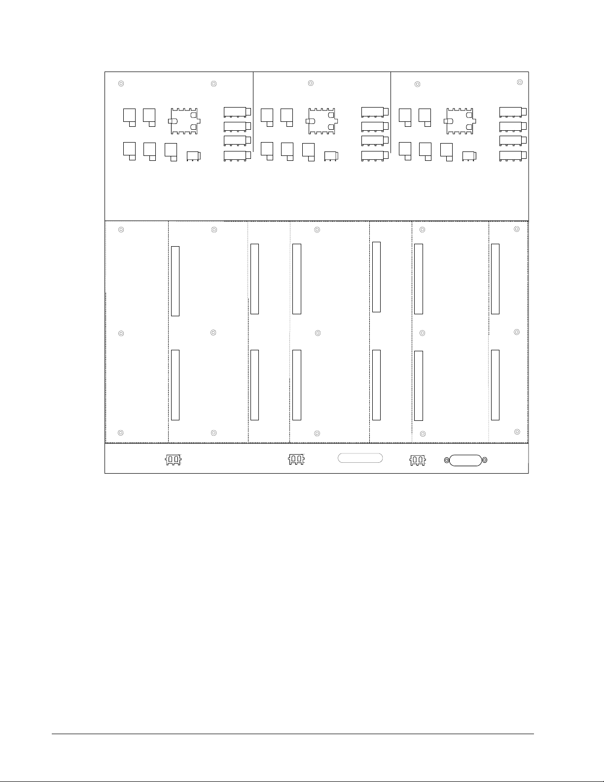
••••
M1
M2
C
EDEX EDCF
J17
M1
J18
M1
EDEX
CROW
BAR
J16
M1
J19
M1
EGDM
CONTROL
J602
J20
J21M1
M1
MEDIA
FAN
CONV
P101 P201
EDEX
EETB
ECTB
EXTB
EPSM EPSMEPSMEGDM EGDM EGDMBlank plate
J15M1
J14M1
J13M1
J12M1
EDEXEDCF
J17
M2
J18
M2
EDEX
EGDM
CROW
BAR
P105 P205
J16
M2
J19
M2
P107 P207
CONTROL
J602
J20
J21M2
M2
FAN
MEDIA
CONV
EDEX
EETB
ECTB
EXTB
J15M2
J14M2
J13M2
J12M2
EDEXEDCF
EDEX
CROW
BAR
P111 P211
J17
J18
C
C
J16
C
J19
C
EGDM
P113 P213
CONTROL
J602
J20
J21C
C
FAN
MEDIA
CONV
EDEX
EETB
ECTB
EXTB
J15C
J14C
J13C
J12C
P117 P217
J1_M1 J1_M2
IS200EPBPG1
Figure 3-2. Exciter Power Backplane
DACA – Ac to Dc Converter
The DACA is an ac to dc converter that is powered by a 115 V ac source and
produces 125 V dc. The DACA and battery source provide a redundant 125 V dc
supply for the EPDM. Two DACAs can be connected to the EPDM if required for
greater power supply reliability.
BARCODE
J1_C
J2C
GROUND
DETECT
3-10
Chapter 3 Printed Wiring Boards Overview GEH-6632 EX2100 User’s Guide
Page 55

••••
Related Board Publications
For a more detailed description of each board's circuitry and application data, refer to
the following documents:
• GEI-100460 IS200EBKP Exciter Backplane
• GEI-100267 IS200DSPX Digital Signal Processor Board
• GEI-100434 IS215ACLAH1 Application Control Layer Board
• GEI-100454 IS200EISB Exciter ISBus board
• GEI-100453 IS200EMIO Exciter Main I/O board
• GEI-100456 IS200ESEL Exciter Selector board
• GEI-100459 IS200EPCT Exciter PT/CT board
• GEI-100457 IS200ECTB Exciter Contact Terminal Board
• GEI-100458 IS200EXTB Exciter Terminal Board
• GEI-100464 IS200EDCF Exciter DC Feedback board
• GEI-100465 IS200EACF Exciter AC Feedback board
• GEI-100461 IS200EGPA Exciter Gate Pulse Amplifier board
• GEI-100466 IS200EDEX Exciter De-Excitation board
• GEI-100467 IS200EGDM Exciter Ground Detector Module
• GEI-100463 IS200EPBP Exciter Power Backplane
• GEI-100462 IS200EPSM Exciter Power Supply Module
EX2100 User’s Guide GEH-6632 Chapter 3 Printed Wiring Boards Overview
3-11
Page 56

••••
Notes
3-12
Chapter 3 Printed Wiring Boards Overview GEH-6632 EX2100 User’s Guide
Page 57

••••
Chapter 4 Terminal Board I/O and Equipment Connections
Introduction
This chapter describes the customer's equipment connections, and inputs and outputs
(I/O) available through terminal board wiring. System cabling to provide desired
functionality is also defined. The information is organized as follows:
Section Page
Power Connections and Analog I/O......................................................................... 4-2
Power Potential Transformer Inputs................................................................. 4-3
Potential and Current Transformer Inputs ........................................................ 4-3
Analog Input..................................................................................................... 4-3
Customer Contact I/O .............................................................................................. 4-4
Power Supply Inputs................................................................................................ 4-6
Line Filter Connections............................................................................................ 4-7
Exciter Internal I/O .................................................................................................. 4-8
Exciter AC Feedback........................................................................................ 4-8
Exciter DC Feedback........................................................................................ 4-8
De-Excitation......................................................................................................... 4-11
Crowbar ................................................................................................................. 4-14
Field Ground Detector ........................................................................................... 4-14
Field Flashing ........................................................................................................ 4-16
Dc Field Flashing Settings.............................................................................. 4-16
Flashing Control Sequence............................................................................. 4-16
Shaft Voltage Suppressor....................................................................................... 4-18
Data Highway Connections ................................................................................... 4-19
Control System Toolbox Connection..................................................................... 4-20
EX2100 User’s Guide GEH-6632 Chapter 4 Terminal Board I/O and Equipment Connections
4-1
Page 58

••••
Power Connections and Analog I/O
Figure 4-1 displays a typical connection diagram of the common power and analog
I/O for an excitation system.
Customer Supplied
12
Power
Flow
+
Generator Field +
To Bridge 1
-
Generator Field -
PT1
3
H1
H2
H3
PT2
H1
H2
H3
P
RI
VA
C :
14
40
0
P
RI
VA
C :
14
40
0
SE
C
VA
C :
12
0
SE
C
VA
C :
12
0
(O
X1
PE
N
O
R
X2
G
R
O
U
X3
N
D
E
D
(O
X1
PE
N
O
R
X2
G
R
O
U
X3
N
D
E
D
PTSW1
1
3
5
PTSW2
1
3
5
CTSW1
2
4
CTSW3
2
4
Control Cabinet
2
4
6
2
4
6
1
3
1
3
TB1
TB2
TB3
1
3
4
3
5
7
9
11
13
15
17
19
21
23
5H
5L
1H
1L
5H
5L
1H
1L
PT
PTPTPT
Fa
nou
t
cir
cui
CT
CT
EPCT
J3
05
J3
08
J3
15
To
EMIO
(M1)
To
EMIO
(M2)
To
EMIO
(C)
2
4
6
8
10
12
14
16
18
20
22
24
1
2
3
4
1
2
PPT
H1
H2
KV
A
12
H3
80
Phase Rotation
3
1
2
P
RI
VA
C :
12
47
0
SE
C
VA
C :
65
0
X1
X2
X3
41AC1
L1
L2
L3
K1
K2
K3
Power Conversion Cabinet
To
Bridge 1
Note: Circuits shown
external to the exciter
are for reference only.
Figure 4-1. Exciter AC Power Supply and PT/CT Wiring
4-2
Chapter 4 Terminal Board I/O and Equipment Connections GEH-6632 EX2100 User’s Guide
Page 59

••••
A redundant PT input for PT
failure detection is possible, and
single-phase sensing can be
supported.
Power Potential Transformer Inputs
In the EX2100 excitation system, a 3-phase source of ac power is converted to a
controlled dc output. This ac input can be from one of several sources. Most
common is a generator terminal connected Y-Delta power potential transformer. The
primary and secondary voltages as well as kVA ratings are sized for the particular
application. An auxiliary bus fed PPT is also commonly used. In industrial
applications where forcing is needed for large motor starting a compound source
(current and voltage) input can be used. This ac input is connected to the bus in the
bridge cabinet and can be isolated by the 41AC1 device for maintenance. It is
monitored by the controls through the EACF board.
Potential and Current Transformer Inputs
Customer supplied 3-phase PT and CT are wired to switches in the control cabinet as
shown in Figure 4-1. The switches are wired to the EPCT. High frequency noise
suppression near the point of signal entry is provided on all input signals to EPCT.
On the board, the two 3-phase generator voltage inputs, nominal 115 V ac, are
brought into PT transformers. Two generator CTs (phases A and C), with either 1 A
or 5 A secondaries, are brought into CT transformers. The resulting low voltage
transformer output signals are cabled to the EMIO board in the control rack.
Generator Voltage Measurement
The cable lengths from the generator PTs can be up to 1000 ft of #12 AWG wire.
The PT secondary outputs are nominally 115 V rms at 50/60 Hz and are fused. On
EPCT, the two transformers make a three-wire open delta voltage measurement,
yielding 1.533 V rms for a 115 V rms input.
In the case of a simplex system the voltage signals are sent through the J305
connector to the EMIO board in the M1 controller. In the case of a redundant system,
the signals are fanned to connectors J305, J308, and J315, and sent to controllers M1,
M2, and C.
Item PT Inputs CT Inputs
Number of Inputs 2, 3 phases each 2, Phases A and C
Volts or Current 10-200 V rms, 115 V rms nominal 0-2 A, nominal 1A, or
0-10 A, nominal 5 A
Frequency 50/60 Hz nominal 50/60 Hz nominal
Burden Less than 1 VA Circuit loading 6.25 VA nominal
Generator Current Measurement
Two generator current inputs from the CTs are wired to non-pluggable terminal
blocks, TB2 and TB3 that support ring terminals. The CTs do not have fused
secondaries. There is a choice of a 0-1 A rms CT input, or a 0-5 A rms CT input. The
cable length from the CT to the EPCT board can be up to 1000 ft., and the wire gage
can be up to #10 AWG. The resulting signals are sent to the EMIO board through the
same connectors as the voltage signals.
Analog Input
The EPCT board provides an analog input for customer use. This input is jumper
selectable for either ± 10 V dc or 4-20 mA. The EMIO samples the input at 2000
samples per second, and the accuracy is better than 1% full scale.
EX2100 User’s Guide GEH-6632 Chapter 4 Terminal Board I/O and Equipment Connections
4-3
Page 60

••••
Customer Contact I/O
Customer contact inputs and relay contact outputs are wired to the ECTB board.
In addition to six general purpose contact inputs, there are two dedicated contact
inputs, wetted by 70 V dc from the exciter, as follows:
• 86G contact input used as a lockout during normal operation
• 52G contact input gives the online status of the generator
ECTB provides four general purpose Form C contact outputs controlled by EMIO.
These are used for 94EX and 30EX and other outputs. For each relay, the coil current
and the status of a relay auxiliary contact is monitored. These feedbacks are cabled to
EMIO in the controller. Refer to Figure 4-2 and Table 4-1.
Table 4-1. General Purpose Relay Contact Characteristics:
Item Description
Customer Power 125 V dc nominal (24 V dc min)
Relay break characteristic
Suppression External suppression supplied by customer on induction loads
Resistive load 2 A 28 V dc
0.5 A 125 V dc
Inductive 1 A 28 V dc 0.007 s (L/R)
0.1 A 125 V dc 0.007 s (L/R)
ECTBG1 is the redundant control version of the ECTB. This fans inputs to three
connectors J405, J408, and J418 that are cabled to the three controllers. For relay
control, the board does two-out-of three voting, and the 70 V dc and 24 V dc inputs
are redundant.
4-4
Chapter 4 Terminal Board I/O and Equipment Connections GEH-6632 EX2100 User’s Guide
Page 61

••••
From M1
J13M1
P70 V dc
ECTBG2 (Simplex)
TB1
From M1
(EMIO)
J405
P24M1
P24D
P24D
Relay
Driver
Four General Purpose Relay Outputs as Above
Relay
Driver
Two Trip Relay Outputs as Above
Coil
K#GP
Coil
K#M1
P24M1
M1
M1
NO
COM
NC
18
19
20
1
5
Customer
Power to
Contacts
125 V dc
Ex. Fault
to Mark VI
Customer
Power to
Contacts
125 V dc
Term. 1&5
Ex. trip to
Customer
86
Red LED
Red LED
To Optocoupler on M1 (EMIO)
Figure 4-2. Customer I/O wired to ECTBG2 Simplex Board
Six Circuits as Above
Current Limit
Current Limit
Circuit
Current Limit
Circuit
P70Vdc
P70Vdc
P70Vdc
33
34
45
46
47
48
TB2
Auxiliary
Contact
Input
52G
Contact
(Closed
online)
86G
Contact
(Open
for Trip)
EX2100 User’s Guide GEH-6632 Chapter 4 Terminal Board I/O and Equipment Connections
4-5
Page 62

••••
Power Supply Inputs
The customer’s ac and dc power inputs are wired to the exciter’s Power Distribution
Module (EPDM), which is located on the left hand side of the exciter power
backplane rack. Figure 4-3 shows the screw terminals for the 125 V dc battery
source, and the 115 V ac suply, AC1. A second ac supply, AC2, can also be
connected.
EPDM Exciter Power Distribution Module
125 V dc
from battery
115 V ac
supply #1
115 V ac
supply #2
N125Vdc
N125Vdc
N125Vdc
AC2N
AC2N
J9
1
2
1
2
1
2
1
2
1
2
1
2
1
2
1
3
10
12
10
12
SPARE
SW7
SW6
SW5
SW4
SW3
TB1
x
x
1
x
2
x
4
x
6
x
8
x
10
x
12
x
14
x
16
x
18
x
20
x
22
x
24
x
x
x
x
x
x
x
x
x
x
x
x
3
5
7
9
11
13
15
17
19
21
23
P125Vdc
P125Vdc
P125Vdc
AC1H
AC1H
AC1N
AC1N
AC2H
AC2H
SW2
SW1
J1C
J1M2
J1M1
J8C
J8B
J8A
1
JDACA1
3
1
JDACA2
3
Figure 4-3. Power Wiring Connections to EPDM.
4-6
Chapter 4 Terminal Board I/O and Equipment Connections GEH-6632 EX2100 User’s Guide
Page 63

••••
Line Filter Connections
The 600 V filter is connected to fuse board LFU1. The 1000 V filter has two filter
circuits and is connected to fuse boards LFU1 and LFU2. The filters are located at
the top of the auxiliary cabinet. Connections to the line filter are shown in Figure 4-
4.
From PPT
L1 L2 L3
DISC 1
LFU2
B-L1
B-L2
B-L3
4
2
F
F
U1
U2
135
6
F
U3
LFU1
Auxiliary Enclosure
Linefilter
L1
L2
L3
L1
L2
L3
4
2
6
F
FU1F
U2
135
U3
GND
GND on
Aux Panel
Figure 4-4. AC Feedback and Line Filters
TB4
Coil1_H
1
Coil1_L
2
Coil2_H
3
Coil2_L
4
TB1
TB2
TB3
480V : 1.6V
EACF1
Control
Enclosure
EKBP
Rack
J5
04
J5
09
J5
14
J5
EMIO M1
04
J5
EMIO M2
09
J5
EMIO
14
To Warm
Backup Bridge B2
C
EX2100 User’s Guide GEH-6632 Chapter 4 Terminal Board I/O and Equipment Connections
4-7
Page 64
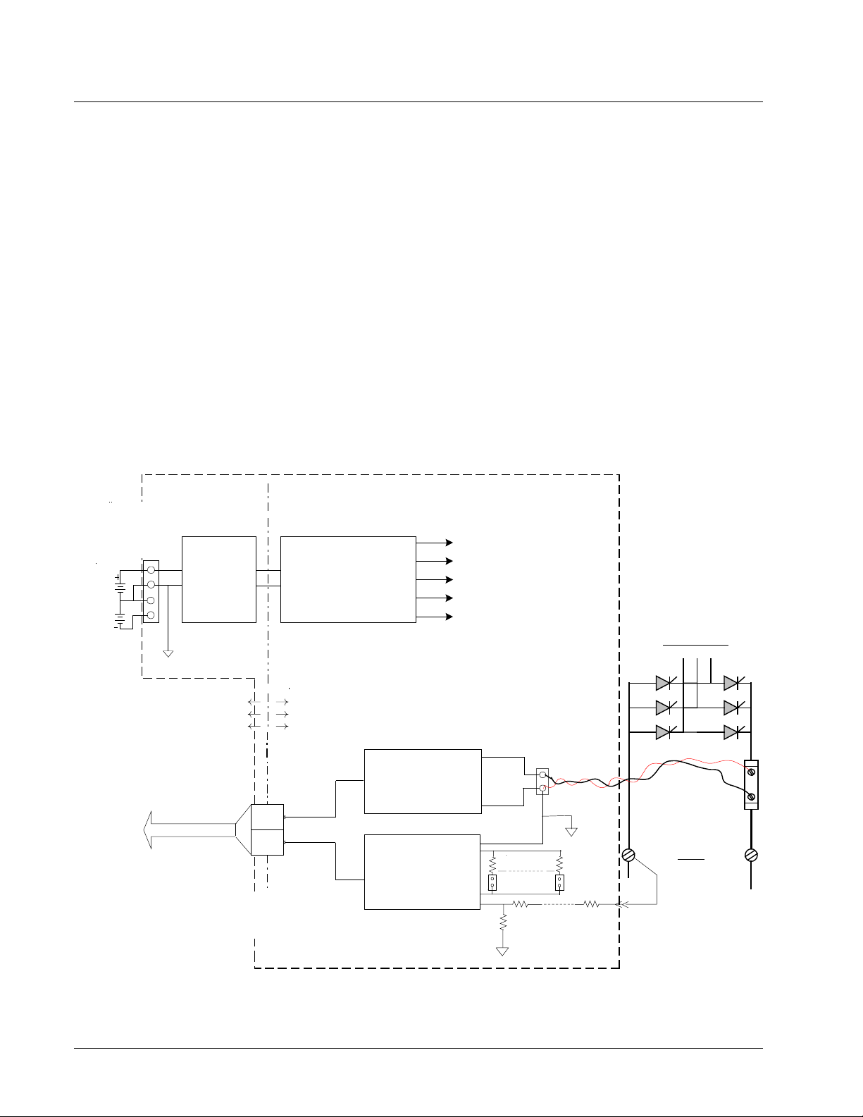
••••
Exciter Internal I/O
Exciter AC Feedback
The EACF board measures the exciter ac supply voltage and current. The terminal
board contains transformers for a 3-phase voltage measurement, and terminals for
two flux/air core coils. The cable between EACF and the EBKP control backplane
can be up to 90 m in length. Cable shield terminal screws attached to chassis ground
are located within three inches of the input screws where applicable. There are two
versions of the circuit board, EACFG1 for up to 480 V rms inputs, and EACFG2 for
up to 1000 V rms inputs. Refer to Figure 4-4.
Exciter DC Feedback
The EDCF board measures field current and field voltage at the SCR bridge, and
interfaces to the EISB board in the controller over a high-speed fiber-optic link. The
fiber optics provides voltage isolation between the two boards, and high noise
immunity. For a circuit block diagram, refer to Figure 4-5. The field voltage
feedback circuit provides seven selector settings to scale down the bridge voltages
appropriate to the application.
+24V
-24V
+/-24Vdc
from
External
Source
To
EISB
board
1
2
3
4
J16
Inverter
COM
30 Vdc
max.
Fiber Optic Link
DC/AC
Tx1
Tx2
V feedbk
Voltage
Isolation
Barrier
EDCF DC Feedback Board
AC/DC Converter
& Power Supplies
I feedbk
Field Current
Amplifier
Field Voltage
Amplifier
+ 24 V dc
- 24 V dc
+ 15 V dc
- 15 V dc
+ 5 V dc
Shunt
mV
input
scale 7
JP7
Ra
R 9
-
+
ACOMH
scale 1
JP1
R1
-
Stab-on
SCR Bridge
Shunt
Field
+
DC
-
+
ACOMH
Figure 4-5. Field Voltage and Current Measurement
4-8
Chapter 4 Terminal Board I/O and Equipment Connections GEH-6632 EX2100 User’s Guide
Page 65

••••
Field Current Feedback
The field current is measured across a dc shunt at the SCR bridge. This generates a
nominal 100 mV signal, which is input to a differential amplifier. The output voltage
from the amplifier ranges from –5 V to +5 V. A VCO produces a linear proportional
frequency of 0 to 2 MHz with an accuracy of 1% of full scale reading. These pulses
drive the LED in the optical isolator coupled to the fiber-optic cable.
Field Voltage Feedback
The bridge voltage is measured across the negative terminal of the bridge and the
positive terminal of the current shunt. After scaling the voltage with the jumpered
resistors, the signals are input into a differential amplifier which controls the voltagecontrolled oscillator (VCO). The VCO produces a linear proportional frequency of 0
to 2 MHz with an accuracy of 1% of full-scale reading. The pulses drive the LED in
the optical isolator coupled to the fiber-optic cable.
EX2100 User’s Guide GEH-6632 Chapter 4 Terminal Board I/O and Equipment Connections
4-9
Page 66
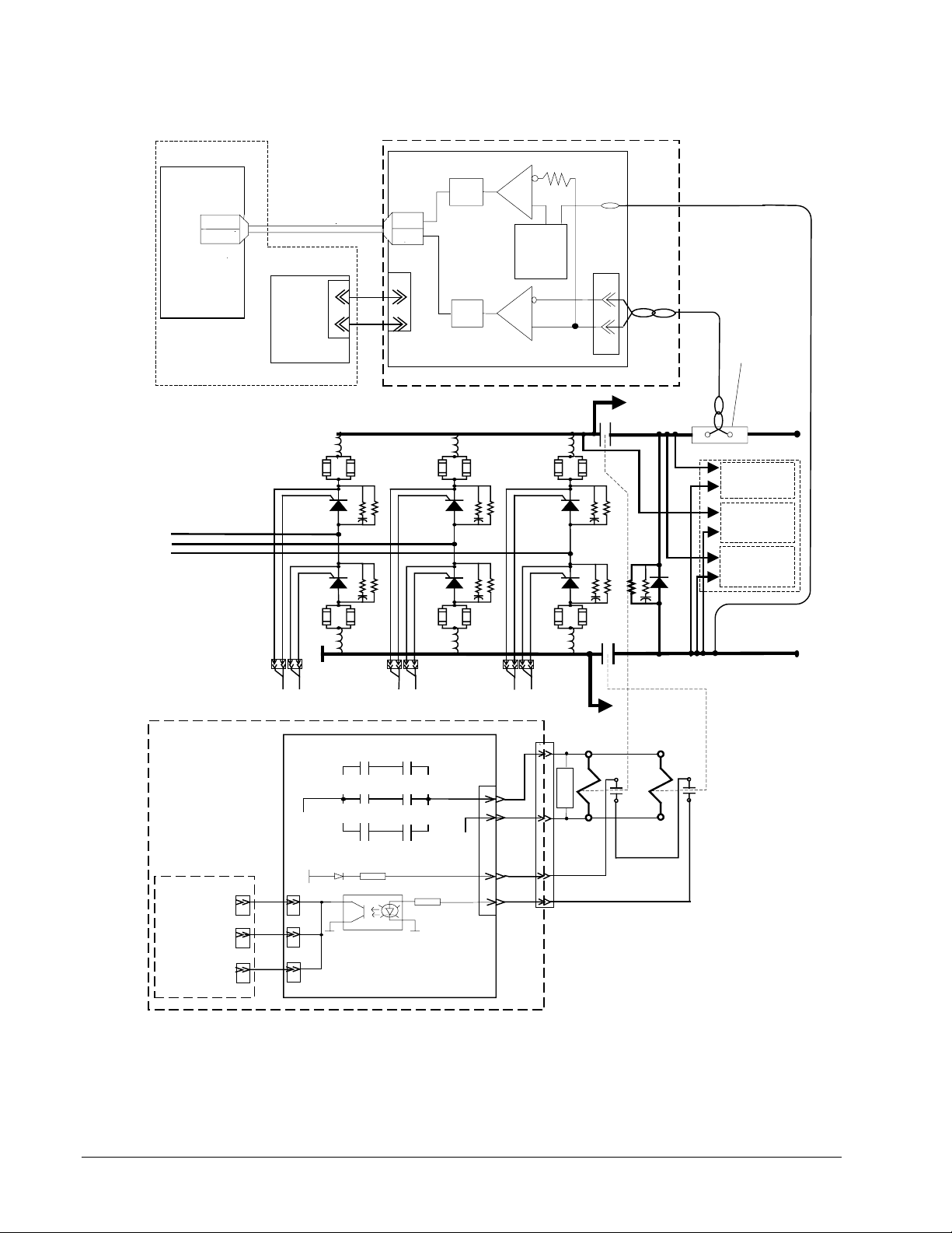
••••
Control Cabinet
EISB M1
Volts
Current
Generator
Field
Duplex Fiber-
Optic Link
PSM1
1
2
Auxiliary Cabinet
EDCF-1
VFOF
CFOF
P2
1
BK
+
2
WH
-
P24VDC
VCO
Voltage
VCO
Current
PPT
Scaling
Shunt (mv)
E1
P1
21
BK
+ -
Dc
Shunt
L1
L2
L3
Control Cabinet
Control Rack
J505
EMIO
M1
J508
M2
EMIO
J515
EMIO
C
J1
SCR1
SCR4
J4
EXTB
P125
P70V
J505
J508
J515
K41_M1
K41_M2
K41_C
Feedback
SCR2
SCR5
J2 J5
K41_M2
K41_C
K41_M1
N125
70V
Return
J6
J3
1
9
2
3
SCR3
J2/3M
SCR6
J6
To Bridge 2
1
FILT1
2
41A
41B
41A
3
4
To Bridge 2
41B
Generator
+ -
1
BK WH
Field +
2
Auxiliary Cabinet
HS +
De-Excit.
FDI-1
53B (W)
Field
Flash
53B (Y)
TB1-1
Shaft
Voltage
TB1-2
Generator Field -
3
4
Figure 4-6. DC Field Circuit Contactor and Control Board
4-10
Chapter 4 Terminal Board I/O and Equipment Connections GEH-6632 EX2100 User’s Guide
Page 67

••••
De-Excitation
During shutdown of the generator, the stored energy of the generator field inductance
must be dissipated. In the EX2100 exciter, this is the function of the EDEX
de-excitation module and field discharge resistor or inductor (when supplied).
Standard de-excitation is provided by a freewheeling diode. For higher performance
applications, the de-excitation module consists of a thyristor (53 mm or 77 mm cell
size) mounted in a large heatsink assembly with attached snubber network.
The EDEX board contains Hall effect conduction sensors. The sensors are mounted
in the air gap of a circular steel core attached to the board. They sense the magnetic
field produced by the field discharge current flowing through the thyristor. Two
independent sensor circuits are used. The EDEX fires the SCR when either of two
control inputs is true or when the anode to cathode voltage of the SCR exceeds a
certain value. The two firing control circuits on the board are powered from separate
power supplies and use separate conduction sensors making them mutually
independent.
The actual control logic inputs used are dependent on the application. When the
exciter shuts down, a P24 V firing control signal is sent to both de-excitation module
firing control circuits. Both firing control circuits send gate pulses to fire the deexcitation SCR. At this point, the main field polarity reversal has occurred making
the SCR anode positive with respect to the cathode. Therefore the SCR conducts and
dissipates the stored energy of the generator field through the field discharge device.
Feedback from either conduction sensor verifies that the discharge circuit has
operated successfully. If both independent firing control circuits fail to fire, the SCR
is fired by the anode firing circuit when the anode to cathode voltage has exceeded
the selected level.
For large exciters, it is possible to connect multiple de-excitation modules together
with one EDEX board configured to be the Master and the other boards configured
to be Slaves. In this case, a firing control signal sent to the Master is relayed to the
Slave modules, firing all modules simultaneously.
EXTB controls the main breaker or contactor in the field circuit. When this opens,
the auxiliary contacts cause an immediate de-excitation commanded by EDEX. Deexcitation controlled by EXTB in both the contactor and breaker mode is shown in
Figures 4-7, and 4-8.
Location of the 41A dc contactor in the field circuit is shown in Figure 4-6.
Contactor 41B is optional. Both contactors are located in the Power Conversion
Cabinet, and are driven from the 41 Close pilot on the EXTB board. Several
auxiliary contacts are used to provide status feedback to the control, and firing
commands to the de-excitation board, EDEX.
An alternative to an 41A and 41B contactor is to use a breaker in the excitation ac
supply or dc field circuit. Normally, the breaker would be a dc field breaker that
ccould break the output while inserting a discharge resistor with the normally open
contact. But, an ac break with the SCR based de-excitation module could also be
applied. The breaker has two coils, 41 Close and 41 Trip, and auxiliary contacts for
de-excitation. Figure 4-8 shows how the breaker interfaces with the EXTB control
board and EDEX.
EX2100 User’s Guide GEH-6632 Chapter 4 Terminal Board I/O and Equipment Connections
4-11
Page 68

••••
Auxiliary Cabinet
Control Cabinet
Converter Cabinet
Generator
Field +
HS+
DEPL
P24
COM
N24
To EPBP
J17M1
De-Excitation
Conduction
Sense Circuit
M1 De-Excit.
Status
M2 De-Excit.
Status
Self Firing
M2 Firing
Command
M1 Firing
Command
P24
1
2
COM
3
N24
To EPBP
N24
N24
1
2
3
J17M2
HS-
Generator
Field -
FDI
2
EDEX
P24V
P24V
J8
EXTB G1 -
(Simplex version is G2)
Contactor Mode
J505
To
M1
1
J508
To
M2
J515
J6
To
C
3
2
4
7
5
8
6
787
1
2
3
4
3
4
8
1
2
M1
J8
Status
2
5
2
5
Status
Feedback
M2
Status
1
3
4
6
1
3
4
6
P70V
70V Ret
Bkr
Bkr
Ct
Ct
41 Trip Relays
not present on
G1 and G2 boards
M1 M2
41 Close
P125
M2 C
CM1
Bkr.
N125
Ct.
1
9
ABA
B
41A 41B
KDEP
N125
P70Vdc
N125
P125
P70VM1
P70VM2
21
J12M2
J9
J12M1
Figure 4-7. DC Contactor Control and Wiring to De-Excitation Board
4-12
Chapter 4 Terminal Board I/O and Equipment Connections GEH-6632 EX2100 User’s Guide
Page 69
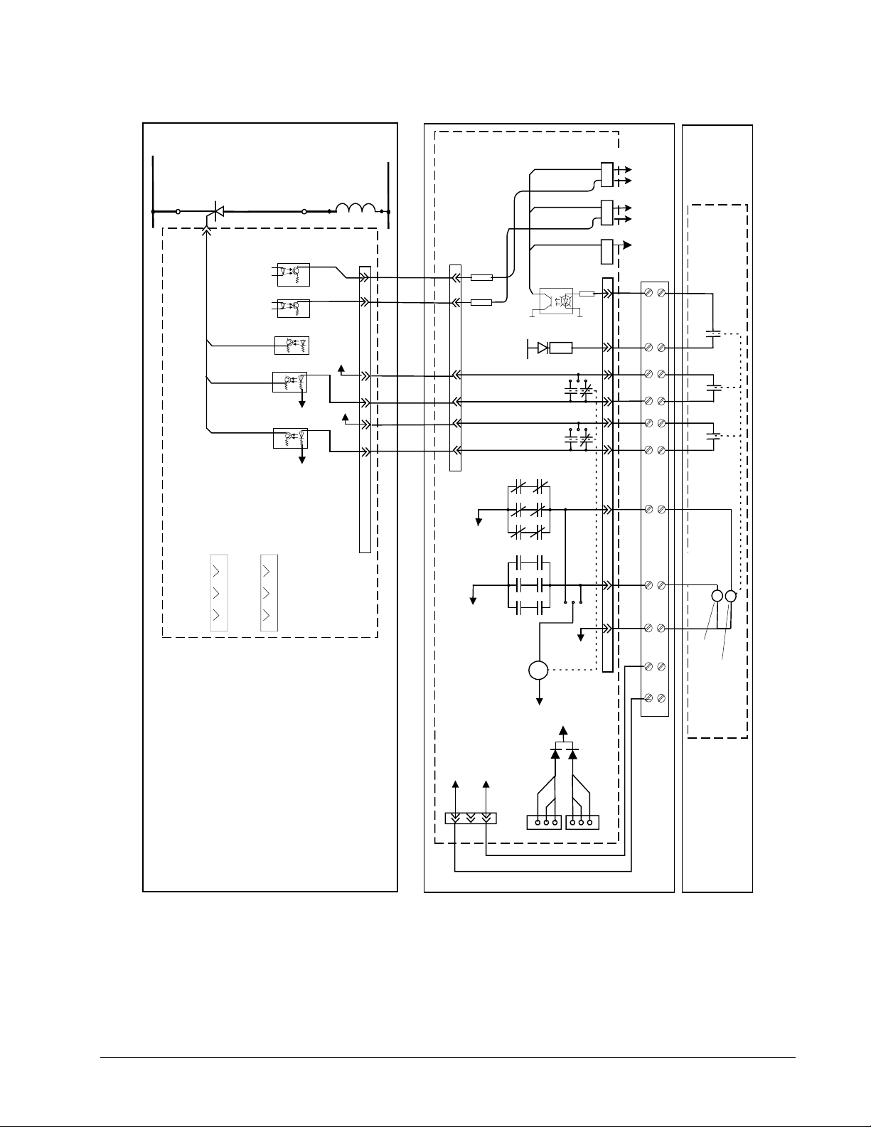
••••
Auxiliary Cabinet
Generator
De-Excitation
Field +
HS+
2
DEPL
Conduction
Sense Circuit
M1 De-
Exc Status
M2 De-
Exc Status
Self Firing
M2 Firing
Command
M1 Firing
Command
HS-
N24V
Generator
Field -
FDI
2
EDEX
P24V
P24V
J8
Control Cabinet
EXTB G3 -
(Simplex version is G4)
1
Breaker Mode
J505
J508
To M1
To M2
Customer
Breaker
J515
J6
To C
CTB
3
J8
M1
2
5
2
5
Status
Status
Feedback
M2
Status
1
3
4
6
1
3
4
6
P70V
70V Ret
Bkr
Bkr
Ct
Ct
2
4
7
5
8
P24
1
2
COM
3
N24
To EPBP
J17M1
P24
COM
N24
To EPBP
J17M2
N24V
1
2
3
41 Trip
P125
41 Close
P125
P125
NC
1
2
J9
3
KDEP
N125
M1
M2 C
CM1
M1
M2 C
CM1
N125
M2
M2
P70VM2
Bkr
Ct
N125
P70Vdc
J12M1J12M2
6
1
9
P70VM1
41
Breaker
A
B
Close
A
B
Trip
Figure 4-8. Ac or Dc Breaker Control and Wiring to De-Excitation Board
EX2100 User’s Guide GEH-6632 Chapter 4 Terminal Board I/O and Equipment Connections
4-13
Page 70

••••
Crowbar
The optional crowbar subsystem limits high negative voltages that can be induced
into the PCM during a pole slip (loss of synchronization) event. Like the deexcitation module, the crowbar will self-fire based on selective field voltage limits. It
includes a discharge resistor, which may be shared with the de-excitation function
when the two are supplied together. This is typically only provided on generators
with salient poles (hydro applications).
Field Ground Detector
The EGDM is an active
system that applies a voltage
to the field circuit.
The generator field is an ungrounded system. The field ground detector (EGDM)
detects field leakage resistance between any point in the field circuit of the generator
and ground. The active detection system shown in Figure 4-9 applies a low
frequency square wave voltage with respect to ground, and monitors for current flow
through a high impedance ground resistor. The square wave is ±50 V dc at 0.2 Hz
frequency. If PRV resistors are present, grounds anywhere in the system can be
detected even while the exciter is not being fired, from the PPT secondary to any
point in the generator field.
The ground detector feedback voltage is sent over a fiber-optic link to the DSPX
where it is monitored and alarmed. The DSPX controls the oscillator voltage over an
adjacent fiber-optic link. In the case of redundant control, if the M1 controller fails,
the oscillator in the M2 channel takes over, as commanded by controller C.
One or three EGDMs are mounted next to the power supplies in the power
backplane.
4-14
Chapter 4 Terminal Board I/O and Equipment Connections GEH-6632 EX2100 User’s Guide
Page 71
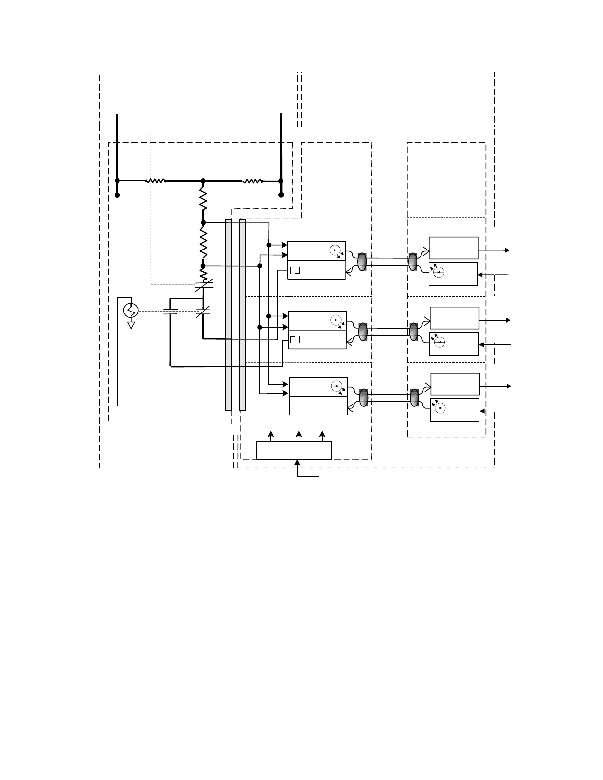
••••
Generator
Field +
Auxiliary Cabinet
From
Flashing
53B
Control Cabinet
Generator
Field -
Ground Detector Attenuator
Module EXAM
J2
Ground
Detector
Voltage
+/-65 Vdc +5V +/-15V
Backplane
EGDM - M1
VCO
Oscillator 1
M2
VCO
Oscillator 2
C
VCO
Control
Power
EPBP
Control
Backplane
EBKP
EISB - M1
Optical
Receiver
Transmitter
M2
Receiver
Transmitter
C
Receiver
Transmitter
Optical
Optical
Optical
Optical
Optical
To DSPX
Counters
Oscillator
control
To DSPX
Counters
Oscillator
control
To DSPX
Counters
Master
Select
Power Supply
P24 V
Figure 4-9. Field Ground Detector
EX2100 User’s Guide GEH-6632 Chapter 4 Terminal Board I/O and Equipment Connections
4-15
Page 72

••••
Field Flashing
The station battery is used to
initiate the field current. An
auxiliary ac source can also
be used.
Flashing current flow is
monitored by the control
through the field shunt.
Field flashing relays 53A and 53B are controlled from drivers on the EMIO board,
through pilot relays on EXTB. In redundant control, the three driver signals actuate
pilot relays on EXTB that are contact voted to output a single voltage. These outputs
actuate the 53A and 53B relays in the Auxiliary Cabinet. The 53A and 53B contacts
put dc voltage from the station battery across the generator field, as shown in Figure
4-10. The field flashing module supplies approximately 15 to 20% of AFNL to the
generator field during the startup sequence.
For ac field flashing, the ac voltage is rectified by a diode bridge and filtered. The
startup sequences and logic are the same.
Dc Field Flashing Settings
Field flashing panels are used to supply a wide range of flashing currents. This
happens if the flashing control fails, leaving the flashing current on continuously.
The flashing current magnitude required for a generator is set by configuring a
maximum and minimum allowable value in the control module.
The current values are preset in the factory based on information supplied. These
values define the envelope in which the hysteretic flashing control holds the field
current during the flashing sequence.
Flashing Control Sequence
A start request is issued by the operator. The optional field contactor(s) closes,
followed by contactor 53B, then 53A. When the field current reaches the maximum
allowable field flash value (typically 15 - 20% of AFNL), contactor 53A opens and
the field current decays through the freewheeling diodes. If the control has not taken
over before the current decays to the minimum field flash current setting, typically
10% AFNL, the sequence is repeated. If the current magnitude exceeds
approximately 25% AFNL, or the control has not taken over after a fixed time delay,
the startup is stopped and a diagnostic alarm is issued.
4-16
Chapter 4 Terminal Board I/O and Equipment Connections GEH-6632 EX2100 User’s Guide
Page 73
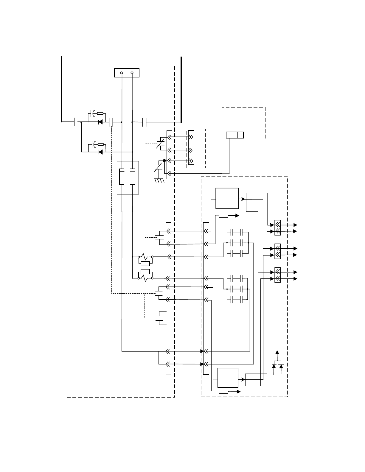
••••
From
Shunt1 +
Auxiliary Panel
Station Battery
125 Vdc
Generator
Field -
Flashing
53B
w v
53A
x
1 2
+
Y
13
FU2
-
53B
x
FBK1
FU1
42
B
B
PTB-1
Y
53B
A
SUP
SUP
53A
Aux
53B
Aux
7
8
5
6
1
2
53A
A
1
2
3
J7
10
J1
Shaft Voltage
Suppresser
EXAM
1
2
3
4
1
J1
2
3
TB1
132
EXTB
C
C
P70Vdc
M2
CM2
M1
M2
C
M1
M1 53B
M2 53B
C 53B
J5M1
J5M2
J5C
M1-EMIO
(J5)
M2-EMIO
(J5)
C-EMIO
(J5)
Current
Limit
Circuit
J7
4
6
4
10
6
M1
K53B relay
contacts
9
2
5
9
2
5
M1
M2
K53A relay
contacts
4
12
3
12
3
Current
Limit
Circuit
M1 53A
M2 53A
C 53A
P70Vdc
P70VM1
P70VM2
P70VDC
Figure 4-10. Field Flashing Control from EMIO and EXTB
EX2100 User’s Guide GEH-6632 Chapter 4 Terminal Board I/O and Equipment Connections
4-17
Page 74

••••
Shaft Voltage Suppressor
Excitation systems, which produce a dc voltage from an ac supply through a solid
state rectification process, cause ripple and spike voltages at the exciter output. Due
to their rapid rise and decay times these voltages are capacitively coupled from the
field winding to the rotor body. This creates a voltage on the shaft relative to ground
that, if not effectively controlled, can damage both journals and bearings. The shaft
voltage suppressor is a filter that conducts the high frequency components of the
induced voltages to ground and limits shaft voltage caused by thyristor commutation
to less than 7 V zero to peak. For the connections to the field, refer to Figure 4-11.
Generator Field +
Shaft Voltage Suppressor
TB1-1
C1
R1
Thyrite
R2
Field
Flashing
TH1 TH2
R5 R6
TB1-3
J1-1
7
8
J1-2
53B
AUX
Generator Field -
C2
TB1-2
R3 R4
Crowbar
HSA
Heatsink
JCY JCX DEPL
EPL1
EPL2
Figure 4-11 Shaft Voltage Suppressor, Thyrite, and Crowbar
4-18
Chapter 4 Terminal Board I/O and Equipment Connections GEH-6632 EX2100 User’s Guide
1
CBRO
2
HSC
Page 75

••••
Data Highway Connections
The Data Highway integrates
several different single
control systems.
Central Control Room
From other Units From other Units
The EX2100 exciter communicates over the same data highway as the Mark VI
turbine control and the HMI. A typical exciter connection to the redundant Unit Data
Highway (UDH) network is shown in Figure 4-12. This shows redundant control
with two ACLAs. The UDH is implemented using commercially available fast
Ethernet switches.
10Base-T cabling is used for short distances between the controller and the T-switch,
and any local HMI. The 10BaseT ports in the ACLA and the T-switch are for RJ-45
connectors. The maximum distance for local traffic at 10 Mbps using unshielded
twisted pair cable is 100 m.
100Base-FX fiber optics can be used for longer distance communication between the
local controllers and the central control room. The 100BaseFX ports in the T-switch
and the Ethernet switch are for SC type fiber-optic connectors. The maximum
distance at 100 Mbps using 100BaseFX fiber-optic cables is 2 km. Redundancy can
be obtained by using two T-switches with an interconnecting cable.
Fast
Ethernet
Switch A
Fast
Ethernet
Switch B
100Base-FX
connections
To local HMI
Viewer,
10Base-T
Local Control Area
T-Switch BT-Switch A
From other Controllers From other Controllers
GE
g
1
ACLA
H1A
Industrial
Systems
2
S
T
A
T
U
S
COM
ENET
Exciter Control
Cabinet
Figure 4-12. Unit Data Highway Connections
Ethernet Port,
RJ-45
10Base-T
connections
Industri al
GE
g
Systems
S
T
A
T
U
S
COM
1
2
ENET
ACLA
H1A
EX2100 User’s Guide GEH-6632 Chapter 4 Terminal Board I/O and Equipment Connections
4-19
Page 76

••••
Control System Toolbox Connection
The toolbox connector on the exciter backplane supports an RS-232C cable, which
connects an external computer to the DSPX board. This connection is for
maintenance purposes. There are three 9-pin connectors located at J303B, J310B,
and J313B to support communication with controllers M1, M2, and C. (Refer to
Figure 4-13).
The UDH can also provide a toolbox interface using the Ethernet port on the ACLA.
This is a 10BaseT port and uses an RJ-45 connector for unshielded twisted pair
cable.
UDH Ethernet Data
Highway to Toolbox
and HMI
Toolbox RS-232C
Computer Cable
Connections
1
2
DSPX
EISB EISB
Key Pad
M1
Tool M1 Tool M2
Test Rings M1 Test Rings M2 Test Rings C
EMIO ESEL ESEL EMIO
J304 J305 J306 J307 J308 J309
E
E
E
G
P
P
C
A
T
1
J405J404 J406 J407 J408 J409
E
E
G
C
P
T
A
B
3
E
G
P
P
C
A
T
2
E
E
G
C
P
T
A
B
4
DSPX ACLAACLA
Key Pad
M2
1
2
DSPX
Key Pad
C
Tool C
EMIOEISB
J315J314
E
P
C
T
J414 J415
E
C
T
B
M1
Power
J509J508J507J506J505J504
E
A
C
J602 J610 J612
F
E
E
X
T
B
E
G
G
P
P
A
A
5
6
E
X
T
B
E
A
C
F
M2
Power
C
Powr
IS200EBKP
J515J514
E
E
A
X
C
F
T
B
Figure 4-13. Toolbox Connections
4-20
Chapter 4 Terminal Board I/O and Equipment Connections GEH-6632 EX2100 User’s Guide
Page 77

••••
Chapter 5 Diagnostic Interface-Keypad
Introduction
This chapter provides operating guidelines for the Diagnostic Interface, more
commonly called the keypad. The keypad is a door-mounted, local control unit that
enables you to:
• Monitor frequency, current, power, and voltage
• Start and stop the exciter
• Set and adjust configuration parameters
• Examine and reset fault conditions
This chapter is organized as follows:
Section Page
Using the Pushbuttons.............................................................................................. 5-2
Reading the Display................................................................................................. 5-5
Changing Display Units.................................................................................... 5-7
Adjusting Display Contrast............................................................................... 5-7
Status Screen............................................................................................................ 5-8
Reading the Meters........................................................................................... 5-8
Alternate Status Screen (Display I/O)...................................................................... 5-8
Using the Menus ...................................................................................................... 5-9
Viewing and Resetting Faults .................................................................................. 5-9
Editing Parameters................................................................................................. 5-10
Parameter Backup........................................................................................... 5-11
Firmware and Hardware Information..................................................................... 5-13
Protecting the Keypad............................................................................................ 5-14
Modifying the Protections .............................................................................. 5-14
EX2100 User’s Guide GEH-6632 Chapter 5 Diagnostic Interface-Keypad
5-1
Page 78

••••
Using the Pushbuttons
The keypad includes membrane-type pushbuttons to access exciter values and to
control the exciter. Tables 5-1 and 5-2 define the pushbutton functions for menu
navigation and exciter control (see Figure 5-1).
g
EX2100 Excitation Control
FVR Feedback
FldCurrAmps
Vmag
Freq_Hz
60.00
Navigation
Status
Menu
0.0 Volts
0.00 Amps
0% 150%
-30%
0% 150%
-30%
Imag
0.000.00
Balance Meter Vars
0.00
Watts
0.00
0.00
Exciter Control
Reset
Faults
Command
Menu
Voltage Level
EnterEscape
Auto
Man
100%
100%
Exciter Health
& State Icons
On
Run (Green)
Stop (Red)
Off
Display:
screens provide analog and digital
Status
representation of exciter functions and values.
Menu
screens provide text-based access to
parameters, wizards, and faults.
Pushbuttons:
Organized into functional groups:
Navigation
Exciter Control
Run
buttons for using the menu
buttons
and
Stop
buttons
Figure 5-1. Diagnostic Interface - Keypad
5-2
Chapter 5 Diagnostic Interface-Keypad GEH-6632 EX2100 User’s Guide
Page 79

••••
Button Function
Table 5-1. Navigation Pushbuttons
Status
Menu
Escape
Enter
Displays the default Status Screen, which shows eight parameters as numbers or
bargraphs. A set of Health icons (displayed at all times; see Exciter Health and State
Icons) provides additional exciter status information.
If pressed while displaying a Menu screen (see Menu Selections), displays the Main
Menu.If pressed while displaying a Status screen, displays the last Menu screen. If held
down, the up and down arrow keys adjust screen contrast
Menu Navigation: Used to highlight (reverse image) an item in a menu of options.
Adjust Contrast, if menu key is held down.
Entry of Numeric Parameter: Used to index through numbers (0-9, ., -) when editing a
parameter.
Entry of Option Parameter: Used to index through 1 – n choices.
(See Parameter Configuration.)
Menu Navigation: Right Arrow button displays the next selected level down in a menu
tree. Left Arrow button displays next level up in menu tree.
Entry of Numeric Parameter: Used to select a digit when editing a parameter.
Entry of Option Parameter or Command Execution: Not functional.
Menu Navigation: Displays the next level up in menu tree.
Entry of Parameter: Displays the parameter list.
Menu Navigation: Displays the next level down in menu tree.
Entry of Parameter: Accepts editing of parameter.
EX2100 User’s Guide GEH-6632 Chapter 5 Diagnostic Interface-Keypad
5-3
Page 80
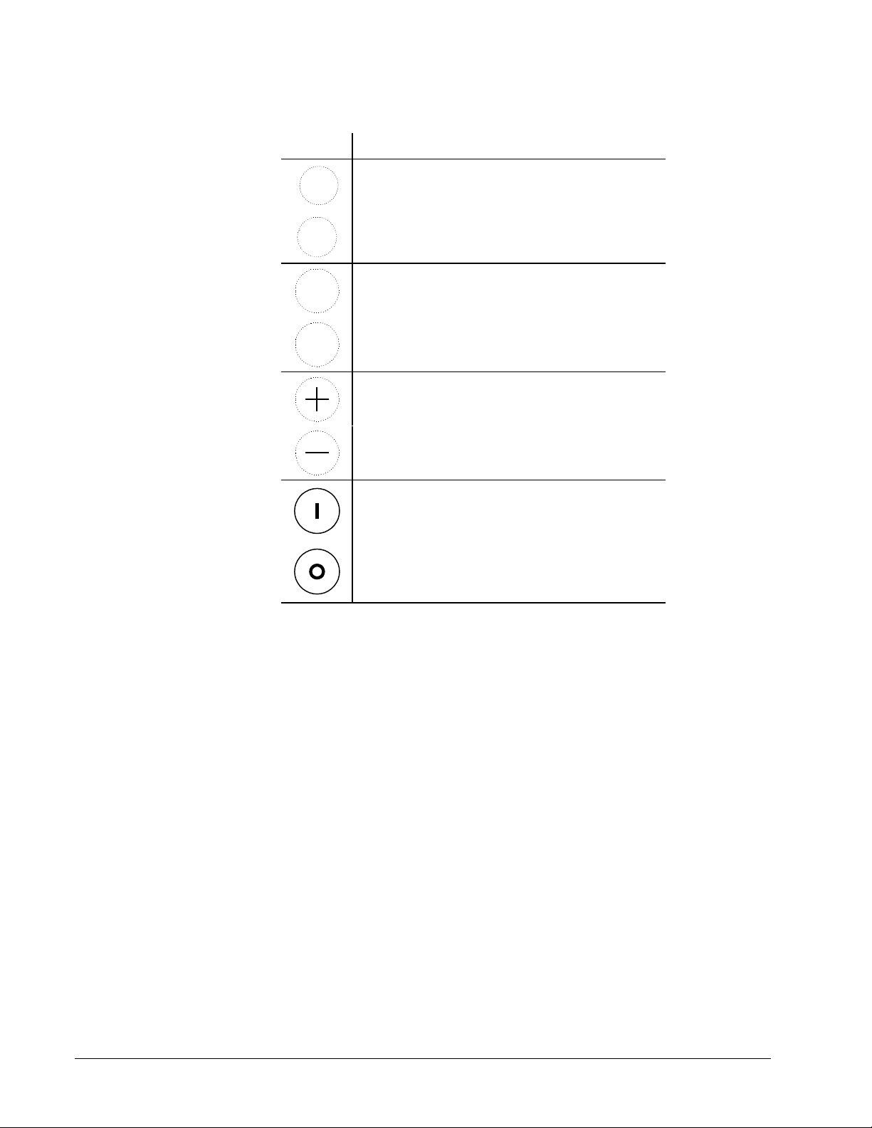
••••
Table 5-2. Exciter Control Pushbuttons
Button Function
Reset
Faults
Command
Menu
Auto
Man
Resets faults.
Quick access to a list of commonly used commands
Selects Auto mode (AC regulator or AVR)
Selects Manual mode (DC regulator or FVR)
Increase voltage, VARS, PF
Decrease voltage, VARS, PF
Run
Stop
5-4
Chapter 5 Diagnostic Interface-Keypad GEH-6632 EX2100 User’s Guide
Page 81

••••
Reading the Display
The keypad displays information as both text and animated graphics. There are two
types of content screens, selected by pressing the corresponding Navigation button:
Status and Menu.
The Status Screen (Figure 5-2) is the default screen that displays after exciter
startup, following an initialization screen. It uses animated meters with associated
text to present exciter performance data. An alternate Status Screen can also be
accessed (see Status Screen).
Text Identifying
Exciter Variable
FVR Feedback
FldCurrAmps
Vmag
Freq_Hz
60.00
0.0 Volts
0.00 Amps
Animated
Heartbeat
Meters
Fault State
0% 150%
-30%
0% 150%
-30%
Imag
0.000.00
Balance Meter Vars
0.00
Watts
0.00
0.00
100%
100%
Limiter
Auto Mode
Running
Online
Figure 5-2. Status Screen Example
The Menu Screen (see Figure 5-3) lists and provides access to menu-based
functions for adjusting parameters, running wizards, and viewing faults (see Menu
Selections).
Main Menu
Fault List
Alarms
Alarm String
Application data
Diagnostic and utility functions
General setup
I/O interface
Figure 5-3. Menu Screen Example
The Exciter Health and State Icons continually show on the right hand side of all
display screens. They indicate if the exciter is functioning correctly and show its
running state. These icons are displayed in five functional groups, as shown below.
You can change the display units and adjust the display contrast, if needed.
EX2100 User’s Guide GEH-6632 Chapter 5 Diagnostic Interface-Keypad
5-5
Page 82

••••
Table 5-3. Exciter Health and State Icons
Group Icon Indication Description
CommunicationsOKAnimated line (its center raises and lowers) shows that there is
Heartbeat
Communications
not established
Auto mode Regulates terminal voltage.
Manual mode Regulates field voltage.Control
Test Mode The exciter is performing a diagnostic test.
Blank Exciter OK When no icon displays, the exciter is operating correctly.
Abnormal Displayed when there are over-ridden parameters.
communication between the keypad and the exciter.
Animated metronome icon shows that the keypad is attempting to
establish communication with the exciter, but cannot.
Fault State
Status
blinking
o
Alarm state Displayed when an alarm condition occurs.
Trip fault Displayed when a fault state occurs.
Stopped Exciter is stopped.
Running Exciter is running.
Limiting
Offline Exciter is offline.
Online Exciter is online.
Field voltage regulator output is greater than field current regulator
or V/Hz or UEL limits are active.
5-6
Chapter 5 Diagnostic Interface-Keypad GEH-6632 EX2100 User’s Guide
Page 83

••••
Changing Display Units
Ø To change the type of measurement units displayed
1. From the Main Menu, select General Setup.
2. Select Display Units.
3. Select the display units parameter to edit it (see below).
4. Highlight, then select the preferred display units.
Press ENTER to accept, ESC to leave
Display units
New Value = Metric (SI)
Present Value = Metric (SI)
Adjusting Display Contrast
Shortcut – Press and hold the
Menu key. Press the Up and
Down arrows to adjust the
display contrast.
ØØØØ To adjust the display contrast
1. From the Main Menu, select General Setup.
2. Then select:
a. Keypad
b. Keypad Functions
c. Adjust Screen Contrast
This displays the following screen.
- CONTRAST ADJUSTMENT -
HOLD UP ARROW TO INCREASE
HOLD DOWN ARROW TO DECREASE
Press ESCAPE to Continue
3. Press the Escape button to save the contrast value and return to the previous
menu.
EX2100 User’s Guide GEH-6632 Chapter 5 Diagnostic Interface-Keypad
5-7
Page 84
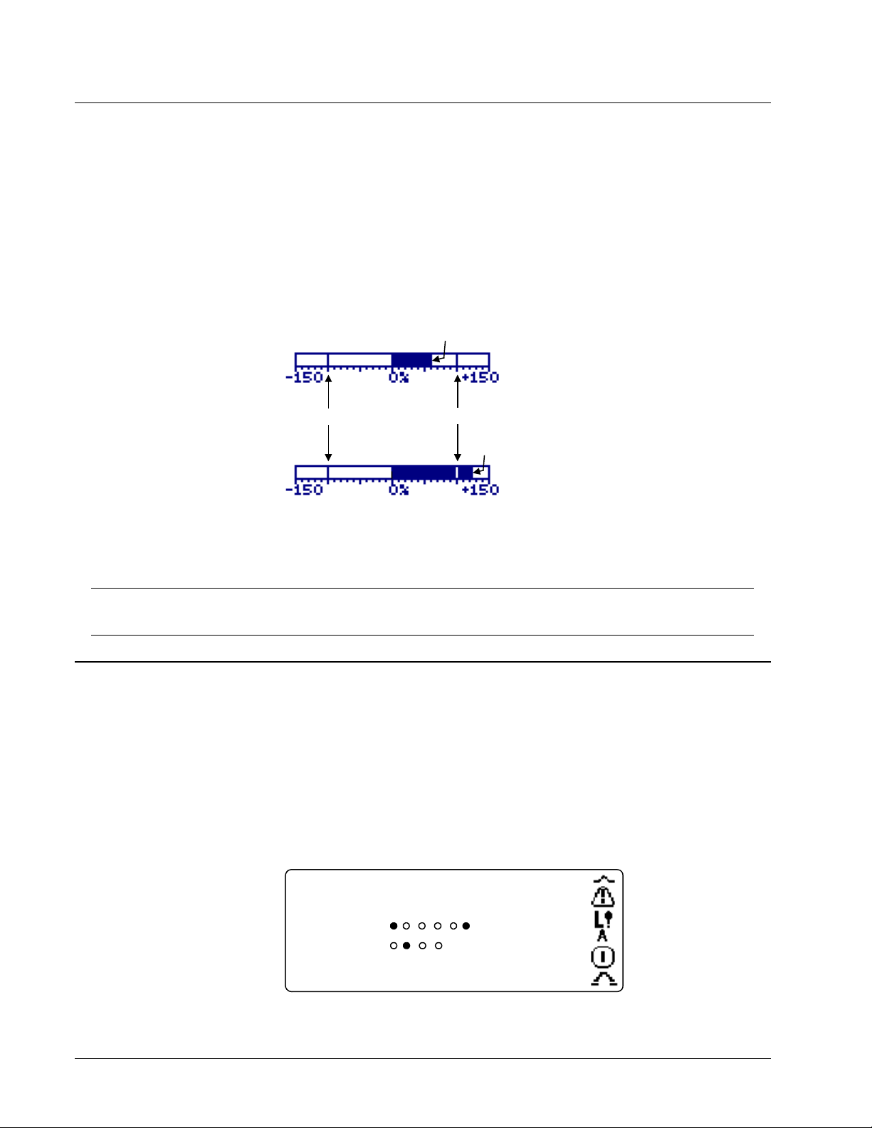
••••
Status Screen
The Status screen displays up to eight variables (parameters). The first two
parameters are displayed both in text and animated meters. Table 5-4 defines the
characteristics of the bar graphs for these parameters.
Reading the Meters
A variable shown as a bar graph is over range when it is either greater than + 100%
or less than –100%. The over range mark is shown with a vertical bar through the bar
graph at the +100% and the –100% marks.
Not Over Range
-100%
Table 5-4. Animated Meter Characteristics (Default) for Status Screen
Bar Graph
Variable
DC bus voltage Magnitude of dc bus voltage (FVR feedback) Percentage of dc per unit volts (VDC_PU)
AC line current Magnitude of ac line current (I_Mag_Fil) Percentage of source top-rated current (I_PU)
Numeric Display Units in Bar Graph
+100%
Over
Range
Alternate Status Screen (Display I/O)
The keypad has an alternate Status screen that displays the status of the general
purpose inputs and outputs. To toggle between the Meter Status Screen and the I/O
Status Screen, press any of the Arrow buttons.
The circle under each heading indicates the status of the corresponding I/O point, as
follows:
•
l = True
• ¡ = False
Display I/O Status
123456
GP Inputs
GP Outputs
5-8
Chapter 5 Diagnostic Interface-Keypad GEH-6632 EX2100 User’s Guide
Page 85
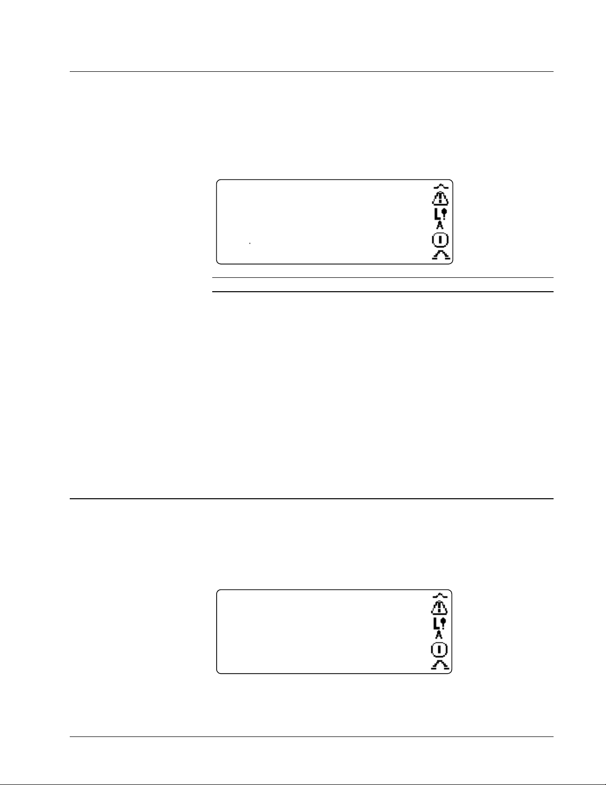
••••
Using the Menus
The keypad’s Main Menu leads to other menu screens, where data can be reviewed
and modified. The Main Menu can be accessed from any screen, as follows:
• If already in a Menu screen, press the Menu button.
• If in a Status screen, press the Menu button once or twice.
Main Menu
Fault List
Alarms
Alarm String
Application data
Diagnostic and utility
General setup
I/O interface
Note The Main Menu selections may vary from product to product.
Use the Navigation buttons to move through the menus, select items, and adjust
values
• Press the Up or Down Arrow buttons to move through and highlight menu
items.
• Press the Enter button to select a highlighted item
• To return to a previous menu screen, press the Escape button, Left Arrow
button, or follow on-screen instructions.
• When a menu has more than one screen:
– Move to the next screen by highlighting the last item on the displayed
screen, then press the Down Arrow button once more.
– If the last menu item is reached, then pressing the Down Arrow button will
wrap back to the first item on that menu.
Viewing and Resetting Faults
When the display indicates either a Trip or an Alarm fault (refer to Reading the
Display), you can view information and reset (clear) current faults, as follows:
1. From the Main Menu, select Fault List, then select Display Active Faults.
The following screen displays.
Faults are displayed in order
of occurrence with the most
recent fault at the top.
86 Trip DC Over-current Trip
115 Trip Bridge 1 Fan 1 BAD
58 Brief Low AC V
95 Field temp alarm
ACTIVE FAULT DISPLAY
--- RESET FAULTS NOW ---
Refer to GEH-6633 Troubleshooting, Preventive and Online Maintenance, for a list
of faults.
EX2100 User’s Guide GEH-6632 Chapter 5 Diagnostic Interface-Keypad
5-9
Page 86
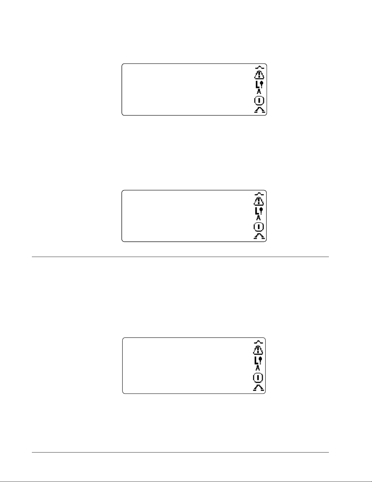
••••
2. To view detail on a particular fault, select that fault (listed on the Active Fault
Display screen). The following screen displays.
SELECTED FAULT - PRESS
Low AC V, B
006:40:11.008
Low AC input volts detected on
the field exciter.
3. Reset the faults either of two ways:
- Select Reset Faults Now in the Fault Display screen.
- Press the Reset Faults button.
Ø To view the exciter’s Fault History (a list of previously cleared faults
and fault resets)
This display list may be
• From the Main Menu, select Fault List, then select Display Fault History.
multiple screens long.
86 Trip DC Over-current trip.
115 Trip Bridge 1 Fan 1 BAD
58 Brief Low AC V
95 Field temp alarm
Editing Parameters
There are two types of parameters that can be changed using the keypad:
• Option parameters lists items (options) for you to select. For example,
• Numeric parameters lists valid digits that you select to create a number.
Ø To edit a parameter
1. From an exciter Parameters screen, select the parameter that is to be changed.
Parameters
GPT_Vrms = <No Value>
VHiTripLev = 1.2
AFFL = 100
TripVHiTrip =
VFFL = 100
100.0
FAULT HISTORY DISPLAY
0 Cleared Fault reset
--- RESET FAULTS NOW ---
True/False is an option parameter.
Trip enabled
This displays either an Option or Numeric parameter screen (see both below) with
the New Value line highlighted.
5-10
Chapter 5 Diagnostic Interface-Keypad GEH-6632 EX2100 User’s Guide
Page 87
••••
2. For an Option parameter:
a. Use the Up or Down Arrow buttons to select a new parameter value.
b. Press the Enter button to accept the change or Escape to exit and keep the
present value.
Press ENTER to accept, ESC to leave
TripVHiTrip
New Value = Trip disabled
Present Value = Trip enabled
3. For a Numeric parameter:
a. Use the Left or Right Arrow buttons to highlight the digit to be changed.
If you continue pressing the Left Arrow button after reaching the left-most
digit of the edit field, the field fills with blanks. Pressing Enter when the
entire number is blanked out saves a <No Value>.
b. Use the Up and Down Arrow buttons to index through the valid digits (0, 1,
2, 3, 4, 5, 6, 7, 8, 9, e, ., -).
The e in the digit selection represents the start of the exponent in scientific
notation. If the e is used, all digits to the right of the e make up the
number’s exponent.
Each new backup overwrites
the previous backup copy,
which cannot be restored.
Press ENTER to accept, ESC to leave
VHiTripLev
New Value = 1.3
Present Value = 1.2
Low Limit = 0.0000000
High Limit = 3.4028239e38
4. When all of the digits have been changed, press Enter to accept the new value
or press Escape to exit and keep the present value.
Parameter Backup
It is good practice to keep a backup copy of the exciter’s working parameter
configuration. You can then restore this file, if needed, or compare it with a reconfigured file to determine differences.
Ø To save active parameters
1. From the Main Menu, select Parameter Backup Functions then select
Save Parameters to Backup.
Save Parameters to Backup
Save current parameter values.
Press ENTER to continue. ESC cancels.
EX2100 User’s Guide GEH-6632 Chapter 5 Diagnostic Interface-Keypad
5-11
Page 88
••••
2. Press Enter to make a backup copy of the parameters or Escape to cancel.
Ø To restore a parameter from backup
1. Stop the exciter. (This function cannot be executed with the exciter running.)
2. From the Main Menu, select Parameter Backup Functions then select Restore
Parameters from Backup.
Press to restore Parameters from Backup
-- WARNING -The active parameter values will be
replaced, and can not be recovered.
Press ENTER to continue. ESC cancels.
3. Press Enter to restore the backup parameters or Escape to cancel.
Restoring parameters from a backup file overwrites the
currently active parameter values, which cannot then be
restored.
Ø To compare the active parameter set to the backup parameter set
1. From the Main Menu, select Parameter Backup Functions then select
Compare Current Parameters to Backup.
BACKUP DIFFERENCES <More↑>
VHiTripLev = 1.3
Backup value = 1.2
AFFL = 112.0
Backup value = 100.0
VFFL = 110.0
Backup value = 100.0
<More↓>
2. Use the Up and Down Arrow buttons to scroll through the list of backup
differences.
3. Press Escape to return to the previous menu.
5-12
Chapter 5 Diagnostic Interface-Keypad GEH-6632 EX2100 User’s Guide
Page 89

••••
Firmware and Hardware Information
Ø To view the firmware versions for the DSPX board and the keypad
From the Main Menu select:
1. General Setup
2. Firmware Version & Hardware Info
3. Display Firmware Version
The following screen displays:
GE Generator Control
EX2100
DSPX Firmware Version: V02.06.00B
DSPX Boot Monitor Version: V02.02.00C
DDI Firmware Version: V02.00.00B
Press ESC to exit
Ø To view exciter hardware information
From the Main Menu select:
1. General Setup
2. Firmware Version & Hardware Info
3. Display Hardware Information
The following screen displays:
GE Generator Control
Hardware Information:
IS200ESELH1APR 5473716
IS215ACLAH1AL 8790070
IS200DSPXH1CAA 7611193
IS200EMIOH1APR 7360814
IS200EISBH1APR 5673766 <More ↓>
ESC to exit
EX2100 User’s Guide GEH-6632 Chapter 5 Diagnostic Interface-Keypad
5-13
Page 90

••••
Protecting the Keypad
To protect the exciter from unauthorized operation or reconfiguration, the keypad
includes two security controls, Password and Privilege Level.
The Password is a 5-digit number that protects the Password and Privilege Level
from being changed by unauthorized personnel. The default Password is 00000.
Privilege Level specifies which operational and configuration functions are disabled
in the keypad. There are three levels:
• Read Only disables both the Exciter Control and the Configuration functions.
An operator can view but not edit parameters.
• Operate & Read Only enables the Exciter Control function, but disables
Configuration functions. An operator can view, but not edit parameters.
• Configure & Operate enables both the Exciter Control and the Configuration
functions. This is the default setting.
If you try to execute a function that is disabled in the active Privilege Level, the
keypad displays the following error message.
Incorrect password!
Press Any Key to Continue
Modifying the Protections
Ø To modify the Password and Privilege Levels
1. From the Main Menu, select:
a. General Setup
b. Keypad
c. Keypad Security
The following screen displays:
Press ENTER to accept, ESC to leave
Enter Password: 00000
5-14
Chapter 5 Diagnostic Interface-Keypad GEH-6632 EX2100 User’s Guide
Page 91
••••
2. Enter the password as follows:
a. Use the Up and Down Arrow buttons to index through the valid digits (0
through 9).
b. Use the Right and Left Arrow buttons to move the cursor to the digit to
edit.
- Press Enter to accept the Password.
- If the password that was entered matches the saved Password value,
you can then modify the Privilege Level or Password.
Keypad Security
Keypad privilege =Configure &
Keypad password =
If it does not match, the keypad displays an error message.
Incorrect password!
Press Any Key to Continue
3. Use the Up and Down Arrow buttons to select either the Privilege Level or
Password.
4. Press Enter to edit the parameter. (See Editing Parameters.)
Note When you modify the keypad password, be sure to select Save Parameters To
Backup. Otherwise, the password stored in the active parameter will not match the
backup parameter set. That causes the Compare Current Parameters to Backup to
identify the Keypad Password parameter as different.
EX2100 User’s Guide GEH-6632 Chapter 5 Diagnostic Interface-Keypad
5-15
Page 92

••••
Notes
5-16
Chapter 5 Diagnostic Interface-Keypad GEH-6632 EX2100 User’s Guide
Page 93

••••
Appendix A Warranty and Renewal Parts
Introduction
When ordering a replacement part for a GE exciter, the customer needs to know:
• How to accurately identify the part
• If the part is under warranty
• How to place the order
This information helps ensure that GE can process the order accurately and as soon
as possible.
To minimize system downtime if repair is needed, GE recommends that the customer
keep a set of spare parts on hand. The Renewal Parts Quotation lists
recommended spares.
Appendix A of this manual provides information to help the user identify and obtain
replacement parts. It is organized as follows:
Section Page
Identifying the Part ................................................................................................. A-2
Renewal Parts List ........................................................................................... A-2
Part Number Structure ..................................................................................... A-2
Warranty Terms ...................................................................................................... A-4
How to Order Parts ................................................................................................. A-5
Data Nameplate ............................................................................................... A-5
ML Number ..................................................................................................... A-5
EX2100 User’s Guide GEH-6632 Appendix A Warranty and Renewal Parts
A-1
Page 94

••••
Identifying the Part
An exciter component, or part, is identified by its assigned part number and
description. The part number is normally found on a nameplate on the component.
The description is included in the system renewal parts list.
Renewal Parts List
The Renewal Parts List is a separate document that lists the parts of a complete
system. This list applies specifically to the equipment furnished on a customer’s
particular application (requisition) at the time of shipment. It includes:
• Part numbers and descriptions
• Quantity used
• Recommended spares to keep onhand
• Normal delivery cycle for obtaining each part
GE provides the Renewal Parts List with the exciter’s custom instructions. If this
document is missing, contact the nearest GE sales office or service representative to
obtain a replacement copy. You need to provide the following information (see
Figure A-4) to correctly identify the system:
• Requisition number
• Model number
Part Number Structure
A GE part number is structured so that different portions of the number identify the
type of equipment and location of manufacture. A part falls into one of four
categories:
• Order-specific assemblies – Major assemblies or items that make up a specific
exciter, constructed from common assemblies
• Common assemblies – Subassemblies used in many GE exciter products, not
just a specific exciter
• Components – Individual parts that make up assemblies
• Printed wiring boards
These categories and the makeup of their part numbers are defined under Order
Specific Assemblies.
A-2
Appendix A Warranty and Renewal Parts GEH-6632 EX2100 User’s Guide
Page 95

••••
Order Specific Assemblies
X
These parts make up the particular exciter. Other items obtained specifically for the
order may also use a similar part number structure, which provides information about
the equipment.
3V
AAA
123
Order
product line
Identifies manufacturer as GE
Systems, Salem,
Sample Part Number for Order-Specific Assembly
###
X
Unit &
sequence number of
Sequence/projec
Unique
to req'n
Common Assemblies
Common assemblies are subassemblies used as components of order-specific
assemblies. Common assemblies are not designed for a particular exciter, but provide
a function used in other GE products.
For example, 36C774524AAG48 is the part number for a cable.
Components
Components are the basic parts that make up assemblies. They represent the
lowest discrete level of a system. Component part numbers consist of a combination
of alphanumeric characters that define the class and specific item. A sample number
is shown below.
104X
109
1ADO38
Item or rating (500 V, 3.2 A FNQ)
Component type (fuse)
Component
Sample Part Number for Component
EX2100 User’s Guide GEH-6632 Appendix A Warranty and Renewal Parts
A-3
Page 96

••••
Printed Wiring Boards
A printed wiring board is identified by an alphanumeric part (catalog) number
stamped near its edge. The structure of a board’s part number is described below.
Note All digits are important when ordering or replacing any board.
The factory may substitute later versions of boards based on availability and design
enhancements. However, GE Industrial Systems ensures compatibility of
replacement boards.
IS 200 DSPX G# A A A
Artwork revision
Functional revision
Functional revision
Group (variation, G or H)
Functional acronym
Assembly level
Manufacturer (DS & IS for GE in Salem, VA)
1
Backward compatible
2
Not backward compatible
3
200 indicates a base-level board; 215 indicates a
higher-level assembly or added components (such
as PROM)
3
1
1
2
Warranty Terms
Sample Board Part Number
The GE Terms and Conditions brochure details product warranty information,
including warranty period and parts and service coverage. The brochure is
included with customer documentation. It may be obtained separately from the
nearest GE Sales Office or authorized GE Sales Representative.
Note Standard warranty is 18 months from shipment or 12 months from when
power is first applied, whichever comes first.
A-4
Appendix A Warranty and Renewal Parts GEH-6632 EX2100 User’s Guide
Page 97

••••
How to Order Parts
Parts still under warranty may be obtained directly from the factory:
(“+” indicates the
international access code
required when calling from
outside of the USA.)
GE Industrial Systems
Product Service Engineering
1501 Roanoke Blvd.
Salem, VA 24153-6492 USA
Phone: + 1 800 533 5885 (United States, Canada, Mexico)
+ 1 540 378 3280 (International)
Fax: + 1 540 387 8606 (All)
Renewals (spares or those not under warranty) should be ordered by contacting the
nearest GE Sales or Service Office. Be sure to include:
• Complete part number, located in the renewal parts list
• Part name
• Exciter model, located in it's nameplate
Data Nameplate
The data nameplate is located on the back of the cabinet door. It provides
information needed when ordering parts or contacting GE for assistance.
ML Number
Each GE lineup, cabinet (panel)/case, and core unit has a unique identifying catalog
number, also called the part or material list (ML) number. This number is
structured to provide information about that equipment. The catalog number links the
equipment to its requisition, drawings, components, materials, specification item,
and shipping documents.
3V
AAA
Identifies manufacturer as GE Industrial
Systems, Salem, VA
Sample Exciter ML (Catalog) Number
EX2100 User’s Guide GEH-6632 Appendix A Warranty and Renewal Parts
XX
###
123
Unit & sequence number of components:
CA## = Case assembly
CD## = Core dc drive controller
CI### = Core ac drive controller
LU### = Lineup, multiple case
assembly
PN## = Panel assembly
RL## = Requisition-level assembly
Sequence/project
Order month/year/
product line
Unique
to req'n
A-5
Page 98

••••
Notes
A-6
Appendix A Warranty and Renewal Parts GEH-6632 EX2100 User’s Guide
Page 99
••••
Appendix B Ratings and Specifications
The actual equipment rating is on your exciter nameplate.
This appendix indicates the range of possible product
offerings but not necessarily the capability of your exciter.
EX2100 Specification Description
Power Conversion Module (PCM)
Single bridge rating 1,000 and 2,000 A dc at up to 1,000 V ac
Parallel bridge rating 8,000 A dc at up to 1,500 V ac, with up to 6 bridges
Forcing requirements 150% of design Amperes (EDA) for 30 s at 40 ºC
Power Sources
Power for the PCM – Voltage source Auxiliary bus
Generator terminals
Compound Source
600 or 1,000 V versions
Power for the PCM – VA (power) 3,251 KVA (1,000 V version)
Power for the PCM - Frequency 3-phase 50/60 Hz, ± 5%
Power to the Cooling Fans (3) 10 A rms, 125 V ac single source
Flashing power 125-250 V dc battery source, with up to 200 A for at least 10 s
380-480 V ac, 50/60 Hz single-phase auxiliary source
Control power (redundant with 2 bridges,
warm backup}
Heat loss in single PCM cabinet 10 KW for a 2000 A, 1,000 V ac PCM
For two ac sources, or one ac and one dc source
Nominal 120 V ac ±15%, with 1 DACA, 10 A rms max.
Battery source 125 V dc, range 80-140 V dc, 10.6 A dc max.
EX2100 User’s Guide GEH-6632 Appendix B Ratings and Specifications
B-1
Page 100

••••
Input/Output
Potential transformers (PTs)2
Current transformers (CTs, 1 or 5 A) 2 Any two phases, single phase is available
86G dedicated contact input 1 Open for trip
52G dedicated contact input 1 Closed for online
Trip rated contact outputs 2 At 125 V dc the relay break characteristics are:
General Purpose contact inputs 6 Customer contact, 70 V dc supplied by ECTB
General Purpose Form C contact outputs 4 At 125 V dc the relay break characteristics are:
± 10 V differential amplifier input 1
Control
Automatic ac Voltage Regulation Proportional + Integral, software implemented
Manual dc Voltage regulator Proportional + Integral, software implemented
Protection Features
Environmental Control & Protection
Base controls cabinet Continuous operation in a 0 to 40 ºC ambient environment
Base power bridge and auxiliary cabinet Continuous operation in a 0 to 40 ºC ambient environment, with 5 to 95%
Storage Temperature -40 ºC to +70 ºC
Humidity 5 to 95% humidity, non-condensing
Altitude Normal operation at 0 to 1000 m. Derate 6% per 1000 m above 1000 m
Cooling Forced air cooling required for PCM cabinet
Contaminants, withstand 10 PPB of
these:
Vibration
Seismic Universal Building Code (UBC) – Seismic Code section 2312 Zone 4
Shipping 72 hours at 0.3 G rms between 4 to 16 Hz
Operating/Installed at Site 1.0 G Horizontal, 0.5 G vertical at 15 to 150 Hz
QTY
3-phase standard, single-phase available
120 V ac nominal
1 VA nominal burden
1 VA nominal burden
Resistive load 0.5 A
Inductive load 0.2 A
Resistive load 0.5 A
Inductive load 0.1 A
± 0.25 % over full voltage range
± 2.0 % over full voltage range
Under Excitation Limiter, (UEL)
Over Excitation protection (76)
Generator Field Ground detection (64F)
Generator Overvoltage protection (24G)
Loss of Excitation protection (40)
V/Hz limit (24) and trip (24T)
Bridge Over Temperature (26)
Field Over Temperature (49)
Phase Unbalance (22)
PT Failure (60)
humidity, non-condensing
Reactive Sulfur, Reactive Chlorine, Hydrogen Sulfide
Sulfur Dioxide, Chlorine Dioxide, Sulfuric Acid
Hydrochloric Acid, Hydrogen Chloride, Ammonia
3 shocks of 15 G, 2 ms impulse for all three axes
B-2
Appendix B Ratings and Specifications GEH-6632 EX2100 User’s Guide
 Loading...