

Page 1
GE Energy Connections
Evolution Series
*
E9000
Motor Control Centers
User Manual
DEH-40472 Rev. 08
Page 2

Evolution Series E9000 User Manual
Contents
Warnings, Cautions & Notes ............................................................2
1. Introduction ...................................................................3
General Description – Vertical Section Enclosures ....................................... 3
General Description – Arc Resistant .....................................................4
General Description – Motor Control Center Buses ......................................4
General Description – Motor Control Center Units .......................................4
Bus Splicing .............................................................................5
Bus Splice Kits ..........................................................................5
2. Receiving, Handling & Storage ..................................................6
Receiving ............................................................................... 6
Handling ................................................................................6
Storage .................................................................................6
3. Installation ....................................................................7
Indoor Enclosures .......................................................................7
Installation of Bottom Entry Conduits ...................................................9
Installation of Flooring ................................................................. 10
Positioning and Joining Sections ....................................................... 11
NEC Work Space ....................................................................... 11
Installation of Top Entry Conduits ...................................................... 12
Exhaust Fan Installation ................................................................ 13
Main Incoming Power Cables ........................................................... 13
Individual Unit Wiring .................................................................. 14
Wiring NEMA Type A Motor Control Centers ............................................ 14
Wiring NEMA Type B Motor Control Centers ............................................ 15
Wiring NEMA Type C Motor Control Centers ............................................ 15
Wiring Between Sections .............................................................. 16
Terminal Blocks ........................................................................ 16
Installation of Standard Motor Control Center Units .................................... 16
Removal of Draw-out Motor Control Center Units. . . . . . . . . . . . . . . . . . . . . . . . . . . . . . . . . . . . . . . 18
Operating Handles, Door Interlocks and Padlocking Provisions .......................... 18
Operating Handle ...................................................................... 19
Pilot Bracket and Door ................................................................. 20
NEMA 3R Outdoor Enclosure Installation ............................................... 20
4. Operation ................................................................... 22
Preparing for Initial Operation .......................................................... 22
Initial Operation of the Motor Control Center ........................................... 22
Door Closing Procedure ................................................................ 23
5. Maintenance ................................................................. 25
Equipment Maintenance ............................................................... 25
Inlet Filter Maintenance ................................................................ 25
Arc Resistant Maintenance ............................................................. 25
Control Power ......................................................................... 25
Control Power Fusing .................................................................. 25
Suggested Maintenance Tools .......................................................... 26
Replacing or Adding Breaker Accessories to Plug-in E or F Frame Circuit Breaker ........ 26
Replacing a Control Power Transformer Mounted Under Disconnect .................... 26
Replace a Compact Starter (1/2 X) ...................................................... 27
Suggested Lifts ........................................................................ 27
Publications Available from GE ......................................................... 27
Renewal Parts ......................................................................... 28
Ordering Additional or Replacement Parts .............................................. 28
Other Information ..................................................................... 28
6. Overload Heaters ............................................................ 29
Heaters for Ther-Mag Circuit Breaker Controllers ....................................... 29
Heaters for Mag-Break Controllers ..................................................... 30
Heaters for Fused Controllers .......................................................... 35
Heaters for NEMA Size 6 and 7 Fused Controllers ....................................... 38
Electr
1
onic Overload for Circuit Breaker and Fused Controllers ........................... 38
Page 3
DEH–40472
Warnings, Cautions & Notes
As Used In This Publication
WARNINGS
Warning notices are used in this publication to emphasize that hazardous voltages, currents, or other conditions
that could cause personal injury are present in this equipment or may be associated with its use.
Warning notices are also used for situations in which inattention or lack of equipment knowledge could cause
either personal injury or damage to equipment.
CAUTIONS
Caution notices are used for situations in
which equipment might be damaged if care
is not taken.
NOTES
Notes call attention to information that is
especially signicant to understanding and
operating the equipment.
This document is based on information available at the time of its publication. While eorts have been made to ensure accuracy, the information contained herein
does not cover all details or variations in hardware and software, nor does it provide for every possible contingency in connection with installation, operation, and
maintenance. Features may be described herein that are not present in all hardware and software systems. GE Energy Connections assumes no obligation of notice
to holders of this document with respect to changes subsequently made.
GE Energy Connections makes no representation or warranty, expressed, implied, or statutory, with respect to, and assumes no responsibility for the accuracy,
completeness, suciency, or usefulness of the information contained herein. No warrantees of merchantability or tness for purpose shall apply.
© Copyright 2017 General Electric Company
All Rights Reserved
2
Page 4
Evolution Series E9000 User Manual
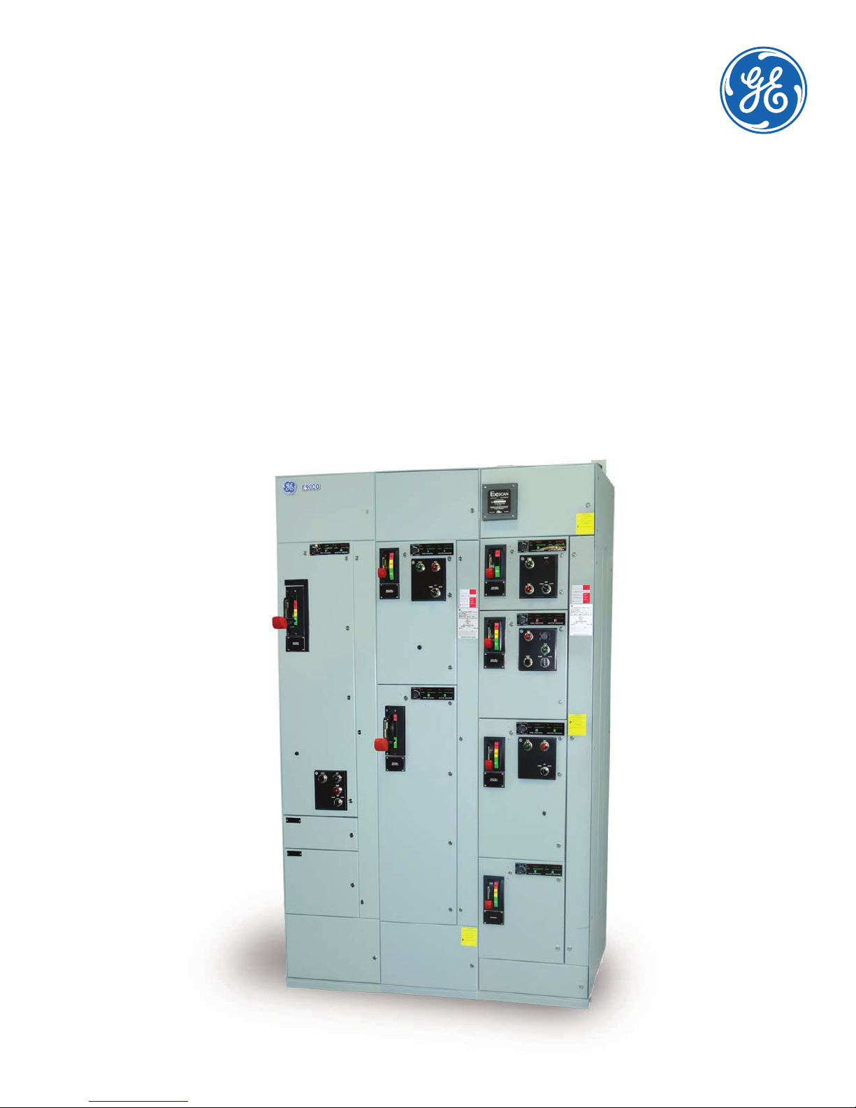
Chapter 1 – Introduction
This publication provides guidelines for installation and
maintenance of Evolution Motor Control Centers, as
shown in Figure 1. The information provided does not
cover all details or variations in this product oering,
nor does it address all possible contingencies to be
met in connection with installation, operation, or
maintenance. Should further information be desired,
contact GE Field Service Administration:
Call GE–RESOLve
1-888-437-3765
Refer to the GE requisition number found on the front
of the equipment when calling for assistance.
Disconnect equipment from all electrical
services before performing any installation
or maintenance work.
For additional information, including safety considerations
for personnel working on this product, see NEMA Standard
Publication No. ICS 2.3, Instructions on the Handling,
Installation, Operation, and Maintenance of Motor
Control Centers.
General Description –
Vertical Section Enclosures
Each Evolution MCC vertical section is assembled with
two full-side sheets having openings near the top and
bottom for lateral busing and wiring between sections.
Multiple sections are joined together at the factory in
three-section (maximum) shipping splits. Each shipping
split is provided with continuous oor sills and a lifting
angle. Floor sills and lifting angles are eld removable.
Each shipping split includes a continuous non-removable
main horizontal bus. Main bus splice bars are provided
within each shipping split for eld connecting main
busses. Refer to motor control center outline drawings
furnished by the General Electric Company for location
of shipping splits within each motor control center
lineup. Hinged doors are provided over horizontal and
vertical wireways. (These doors can be removed by
extracting the hinge pins inside the doors.)
Vertical sections are normally provided with a top (12"
high) horizontal wireway and a bottom (6” high) horizontal
wireway. Each Arc Resistant vertical section is provided
with a vertical (3.85" wide) wireway.
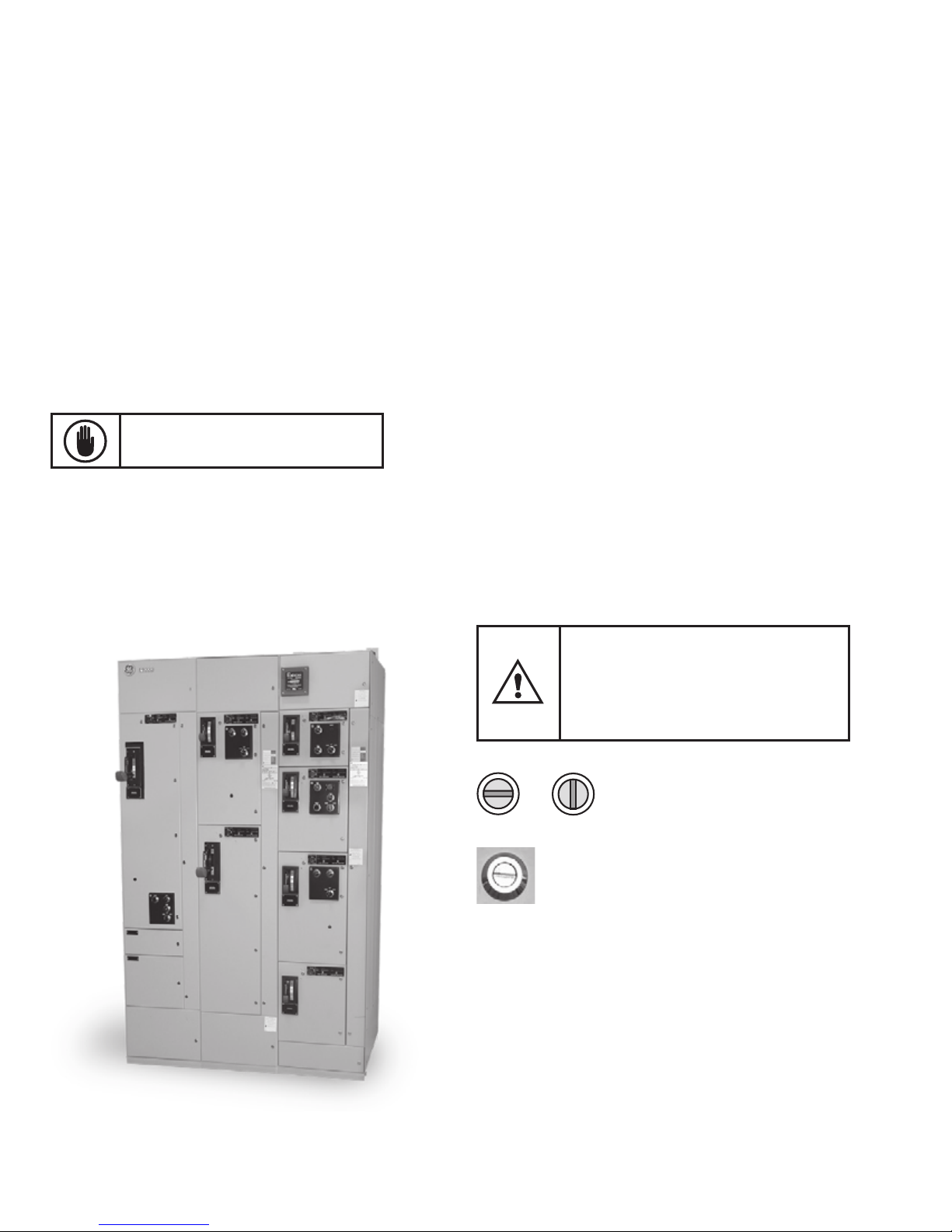
Figure 1. Evolution Series three-section lineup
To open unit doors, rotate the latches 90'
counter-clockwise until the screwdriver slots
or knobs are vertical.
To open wireway doors, rotate the latches 90'
clockwise until the screwdriver slots or knobs
are vertical.
Secure Open
Unit Door Latch shown
in secure position
Because of the great variety of motor controller
assemblies and components provided within industrial
motor control centers and to satisfy oor-space limitations
at installation sites, a large variety of vertical section
dimensions are provided, as follows:
1
• Section Height: 90", 78"
, 66"1 etc.
• Section Width: 20", 24", 30" etc.
1
• Section Depth: 13"
, 20", 22" or deeper
for large assemblies.
1
Not available in Arc Resistant
3
Page 5
Evolution Series E9000 User Manual
General Description –
Arc Resistant
The Arc Resistant sections are built with increased
structural capacity. The main enhancements are thicker
gage of steel, latches, hinges, and metallic PD brackets.
In addition, there are two versions available with and
without a plenum. The plenum option adds 12" to the
top of the 90" section. The plenumless option should
have a 4' clearance on top of the MCC. The top (12"
high) horizontal wireway door and the bottom (6" high)
wireway door utilize multi-turn latches to secure the
doors. The remaining latches are ¼ turn (with options
for closed status indication). There is no variation in the
units between Arc Resistant and standard E9000 other
than the unit door. Additionally, the Arc Flash Mitigation
units are compatible in Arc Resistant design with
Arc Resistant/Arc Flash Mitigation door.
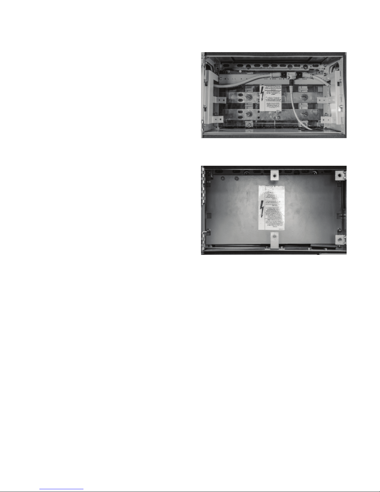
Figure 2. Horizontal bus with Lexan barrier
General Description –
Motor Control Center Buses
The main horizontal power bus is located at the top of
the vertical section. The bus bolted joints are accessible
from the front by loosening the barrier mounting screws
®
and sliding the Lexan
the main bus. Figure 2 shows a horizontal power bus
with its Lexan barrier. For Arc Resistant design, uses
this same Lexan barrier with additional Metallic dead
front barrier.
The vertical bus, either 300A or 600/850 A, is connected
with two bolts per phase to the main bus. The phase
relationship is A–B–C from top to bottom and left to
right, as viewed from the front.
A continuous horizontal ground bus, sized in accordance
with the National Electrical Code, is provided near the
bottom of all motor control centers.
An optional vertical ground bus can be provided in each
section providing additional grounding. A neutral bus is
provided, when specied, in the bottom of the incoming
section or in the bottom of all enclosure(s) as specied.
bus barrier up and forward from
Figure 3. Metallic horizontal bus barrier for Arc Resistant design
General Description –
Motor Control Center Units
Consult Publication DET-291 for detailed listings of
Evolution MCC units.
Plug-in units are supplied with stabs rated at either
250 A or 600 A. Arc Flash Mitigation (AFM) units are
supplied with retractable stabs, mechanical interlocks,
racking screw, and visual stab and shutter indicators. AFM
units are available in plug-in or stab-bolt conguration.
Installation and operation of units, both standard and
AFM, are described on page 14 of this guide.
As shown in Figure 3, the Arc Resistant MCC will include
a metallic main bus barrier in addition to the standard
Lexan barrier.
4
Page 6

Evolution Series E9000 User Manual
Bus Splicing
Main, neutral and ground bus splice bars (with all
associatedhardware) are furnished, as necessary, to
join sections together. They are located in the rst
section tothe right of the joint. See Figures 13, 14 and
15 for approximatedimensions for main, neutral, and
ground bus.
Remove the top Lexan barrier, as shown in Figure 11 and
Figure 12, to access the main bus. Refer to instruction
drawings in splice kit. See Table 2.
Arc Resistant design has metallic barrier in addition to
the Lexan barrier which also must be removed to
access the main bus. Arc Resistant shipping splits will
arrive with end caps. When bus splicing, please remove
these end caps to make connection, only the furthest
most left and right end caps shall remain.
Figure 11. Horizontal bus with Lexan barrier
Table 1. Torque values for various bolt sizes and joint types
Bolt Size
5/16-18 5–9 7–12 6.5–9 9–12
3/8-16 12–16 16–22 10–15 14–20
1/2-13 30–39 41–53 25–35 34–47
5/8-11 65–80 88–108 35–45 47–61
3/4-10 125–150 169–203 50–75 68–102
Note: When assembling or connecting to aluminum bus, apply a suitable joint
compound between the contacting surfaces.
Copper Joints Aluminum Joints
lb-ft N-m lb-ft N-m
Bus Splice Kits
Table 2. Bus Splice Kits
Splicing From / To E9000/E9000
Size
Main Bus Splice
Amps
Standard Splicing
1200 110C1735G7SM 1 1/2 x 2 100K 110C1253TG1
1600/
2000
2500 110C1735G13SM 2 1/2 x 2 100K 110C1785TG1
N3R and Spacer Shells
1200 110C1735G16SM 1 1/2 x 2 100K 110C1253TG1
1600/
2000
2500 110C1735G13SM 2 1/2 x 2 100K 110C1263TG1
*Included in kits
Note: Standard plating is tin. Refer to factory for alternate plating.
Assembly Kit
600 110C1735G1SM 1 1/4 x 2 65K 110C1258TG1
800 110C1735G4SM 1 3/8 x 2 65K 110C1256TG1
110C1735G12SM 2 1/2 x 2 100K 110C1263TG1
600 110C1735G14SM 1 1/4 x 2 65K 110C1258TG1
800 110C1735G15SM 1 3/8 x 2 65K 110C1256TG1
110C1735G17SM 2 1/2 x 2 100K 110C1263TG1
Bars/
Phase
Copper
(thick x
width)
(in.)
SC Rating
600V Max.
(sym.
amps)
Splice
Instruction
Drawing*
Loosen screw, lift and
pull barrier forward
Figure 12. Horizontal bus barrier mounting slot and screw
5
Page 7

Evolution Series E9000 User Manual
Chapter 2 – Receiving, Handling & Storage
Receiving
Before leaving the factory, the motor control center is
given a nal mechanical and electrical inspection and
is packed in accordance with the best practices for
electrical equipment.
On receipt of any apparatus, make an immediate
inspection for any damage or loss of equipment in
transit. Should damage or missing material be noted,
le a claim immediately with the carrier and notify
the nearest oce of the General Electric Company.
Information such as a description of the damage, the
shipping crate numbers, the requisition numbers and
the panel catalog number should accompany the claim.
Handling
Motor control center sections are always shipped in an
upright position, in single or group sections. Sections
must be maintained in an upright position during all
handling.
Figure 5. Positioning the MCC with rollers
Storage
If it is necessary to store the equipment for any length
of time, be sure to observe the following precautions:
• Uncrate the equipment.
• Store the equipment in a clean, dry, humidity-controlled
area at moderate temperature. Cover with a suitable
canvas or heavy-duty plastic cover to prevent entrance
of foreign material.
Never attempt to jack, lift, or move the equipment at
points other than the lifting angle or oor sills. Use two
or more chains or cables to distribute the weight evenly.
Pinch bars, pipe rollers or slings are useful implements
for handling equipment; but be careful to maintain
distributed loading and to always apply leverage at the
oor sills and/or lifting eyes. Figures 4 and 5 illustrate
typical handling techniques.
Figure 4. Using standard lifting angles
or lifting eyes to hoist the MCC
• If equipment must be stored in cool or high humidity
areas, in addition to completely covering the equipment,
provide a heat source to prevent condensation of
moisture in the equipment. Energize space heaters (if
furnished in the equipment) or place a standard 120volt lamp rated at 75 watts inside the bottom of each
vertical section.
6
Page 8
Evolution Series E9000 User Manual
Chapter 3 – Installation
Before any installation work is begun, consult all
drawings furnished by the GE as well as all applicable
contract drawings for the particular installation.
Pay particular attention to the location of units in the
motor control center and their relations to existing or
planned conduits and busways.
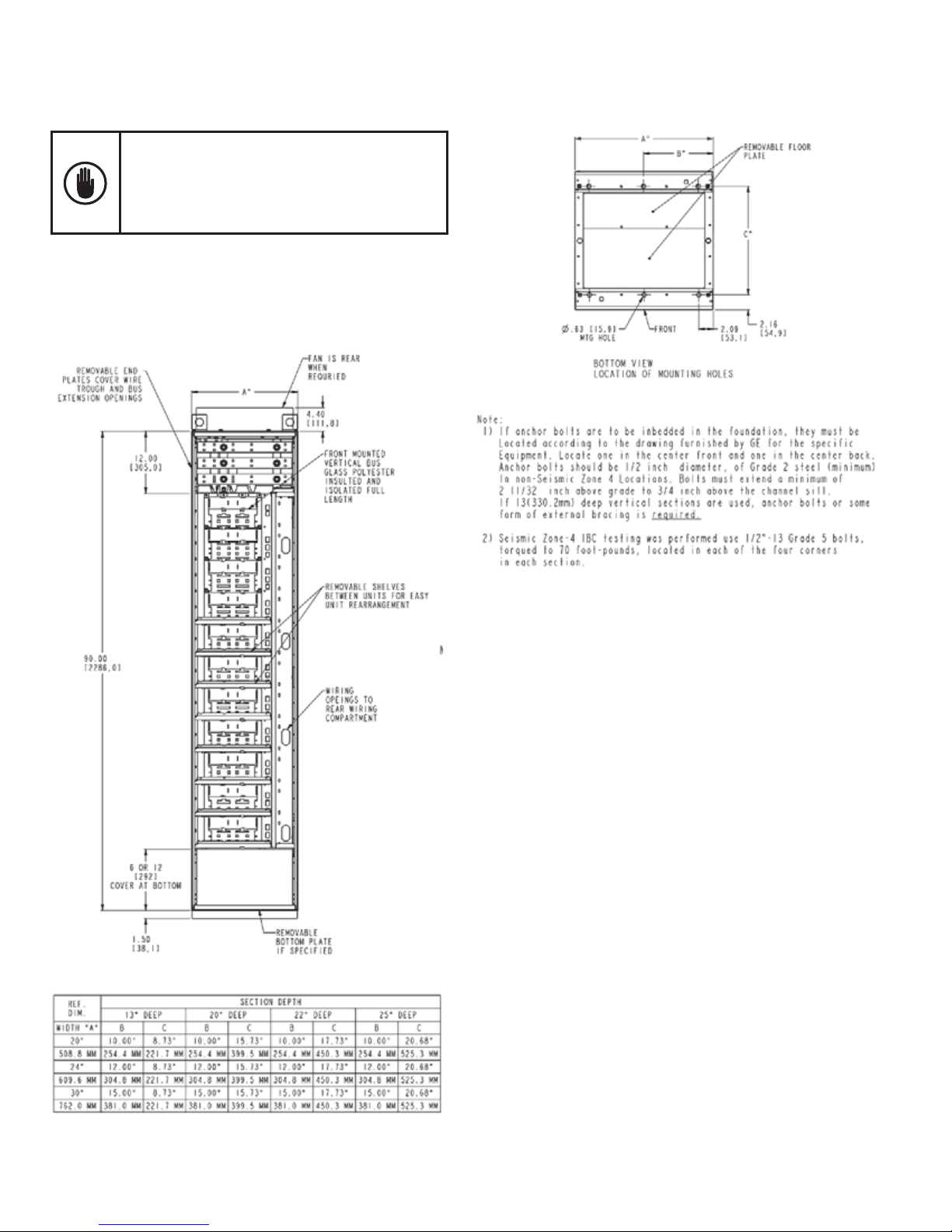
Indoor Enclosures
Front Elevation and Mounting Locations
(13", 20", 22" & 25" Deep Sections)
7
Page 9
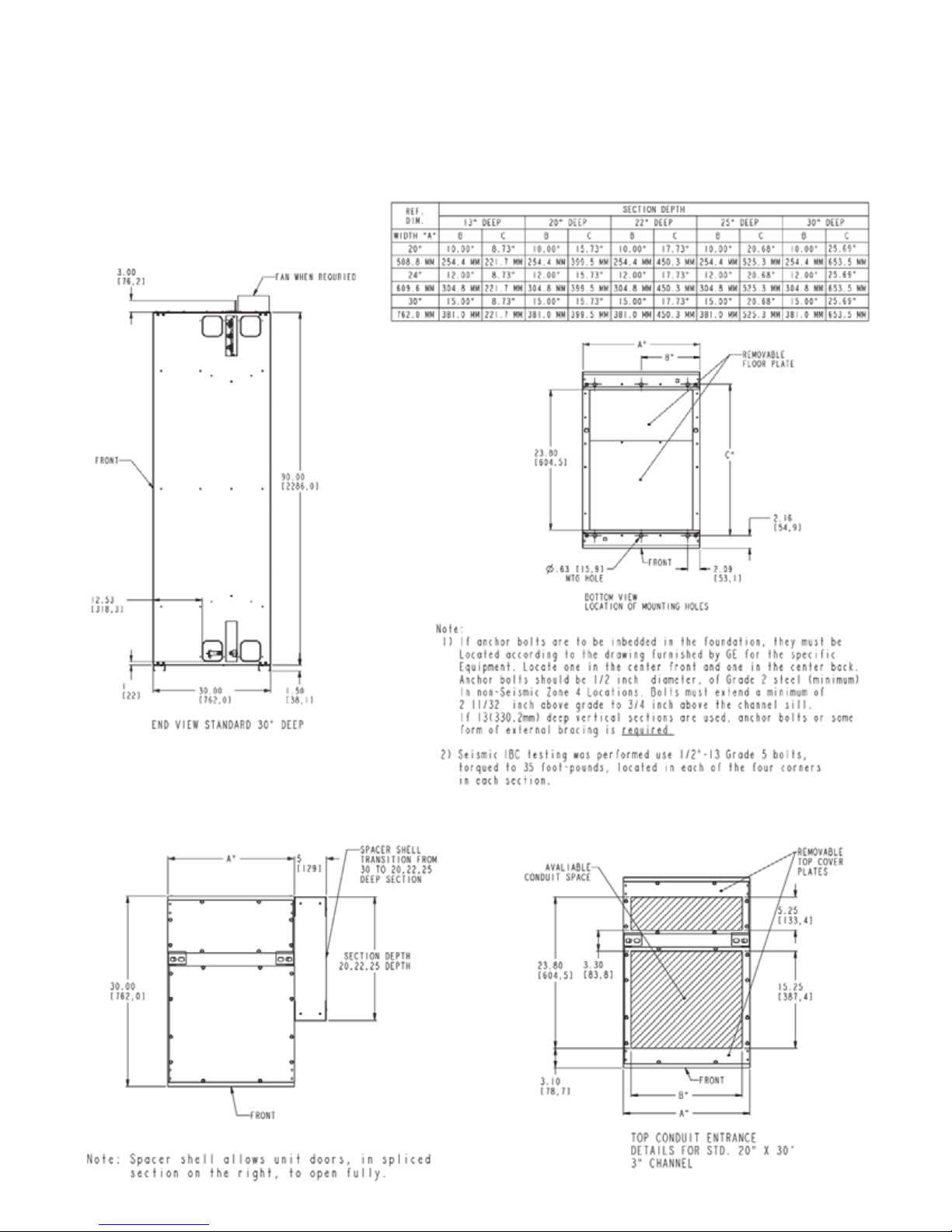
Evolution Series E9000 User Manual
Indoor Enclosures
Elevation and Mounting
30" Deep Sections 600A to 1200A Main Bus
Top Conduit Entry 30" Deep Section
8
Page 10
Evolution Series E9000 User Manual
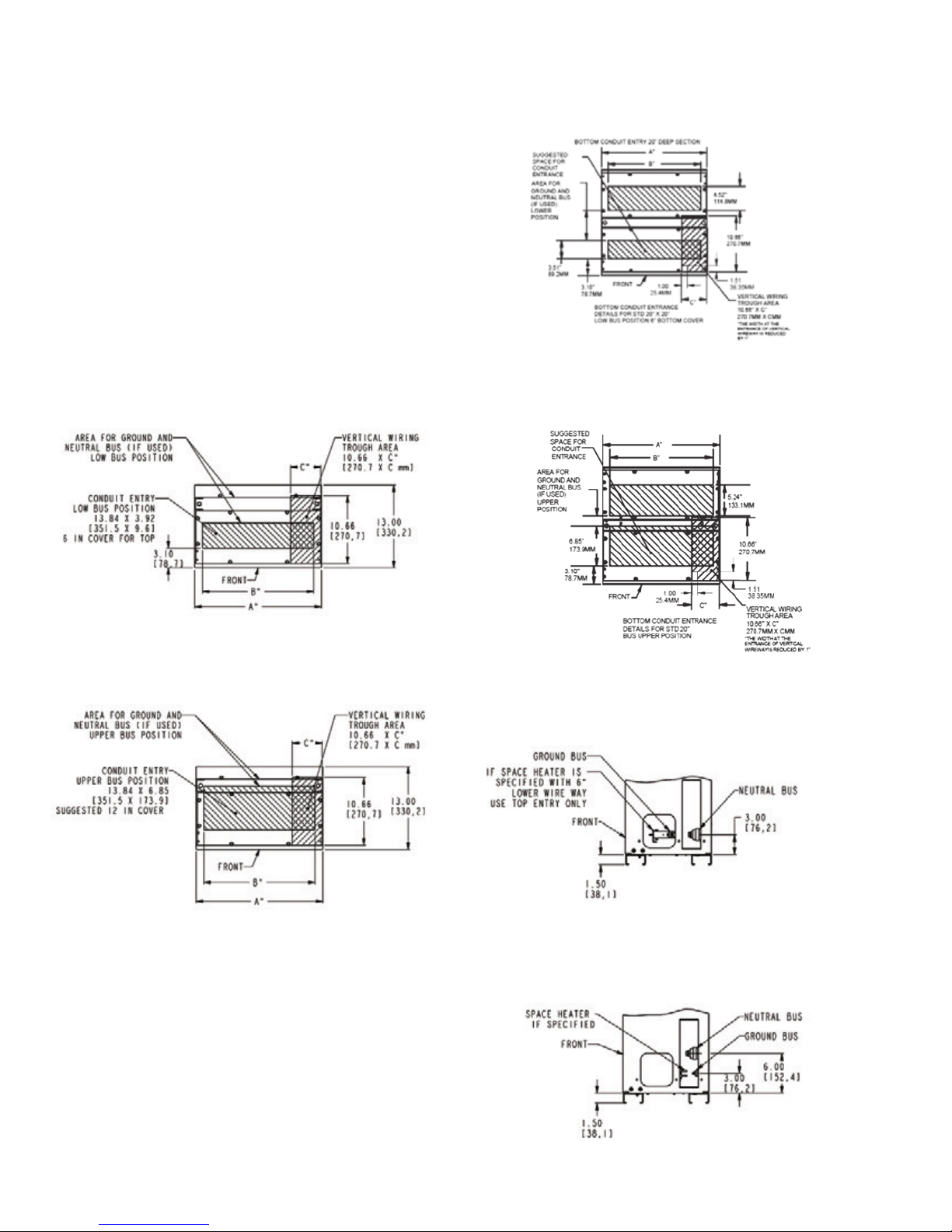
Installation of Bottom Entry Conduits
Conduits can be stubbed in after the location of the
motor control center lineup has been established. Conduit
should be stubbed approximately 2 inches (51mm)
above the nished oor line. Figure 6 and Figure 7 show
the conduit entrance space available at the bottom of
standard sections. Exceptions to this available space rule
are indicated on drawings furnished by GE for specic
installations. Center the conduit beneath the section
vertical wireway to facilitate direct cable entry. Note:
Bottom rear entrance should only be used with full
rear accessibility.
Figure 6C (Arc Resistant). Bottom conduit entrance for standard
20-inch deep section, low bus position, 6-inch bottom cover
Figure 6A. Bottom conduit entrance details for standard 13-inch
deep section, low bus position
Figure 6B. Bottom conduit entrance details for standard 13-inch
deep section, bus upper position
Figure 6D (Arc Resistant). Bottom conduit entrance details for
standard 20-inch deep section, bus upper position
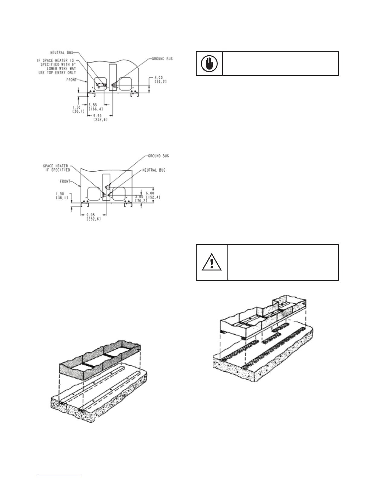
Figure 7A. Low bus position of ground and neutral bus (minimum
available space for conduit entry) in 13-inch deep section, 6-inch cover
9
Figure 7B. Standard position of ground and neutral bus with 12-inch
cover compartment at the bottom of MCC
Page 11
Evolution Series E9000 User Manual
Figure 7C. Low bus position of ground and neutral bus (minimum
available space for conduit entry) in 13-inch deep section, 6-inch cover
Surface under motor control center base must
be of non-combustible material unless bottom
covers are installed in each vertical section.
The overall height of the equipment should be considered
with respect to headroom, top conduit entry space and
alignment with other equipment.
Note:
• If anchor bolts are to be imbedded in the foundation,
they must be located according to the drawing furnished
by GE for the specic equipment. Locate one in the
center front and one in the center back. Anchor bolts
should be 1/2" in diameter, of Grade 2 steel (minimum)
in non-seismic locations. Bolts must extend a minimum
of 2 11/32" above grade to 3/4" above the channel
sill. If 13" (330.2mm) deep sections are used, anchor
bolts or some form of external bracing is required.
• Seismic Zone 4/IBC testing was performed using 1/2" –
13 Grade 5 bolts, torqued to 70 foot-pounds, located in
each of the four corners in each section.
Figure 7D. Upper position of ground and neutral bus (maximum
space available for conduit entry), 6-inch bottom cover
Installation of Flooring
For most installations, the MCC oor sills can rest on the
nished oor. The foundation for the equipment should
be level and even. Although not normally required, the
purchaser may elect to install, level and grout the steel
members or MCC oor sills in the oor, as illustrated in
Figure 8 and Figure 9. If the oor sills are removed, lifting
and moving the shipping sections must be done carefully.
If there are vertical sections of varying depths
(such as 13, 20, or 22 inches) in a single lineup,
the fronts of the sections must be lined up for
proper alignment of the main bus bars.
Figure 9 illustrates this point..
Figure 9. Installing steel oor members
Note the front alignment of the 13-inch-deep section
Figure 8. Control center oor sills grouted to the oor before
installation to provide a level foundation
Note: Cannot be rolled (as in Figure 5) without oor sills
10
Page 12
Evolution Series E9000 User Manual
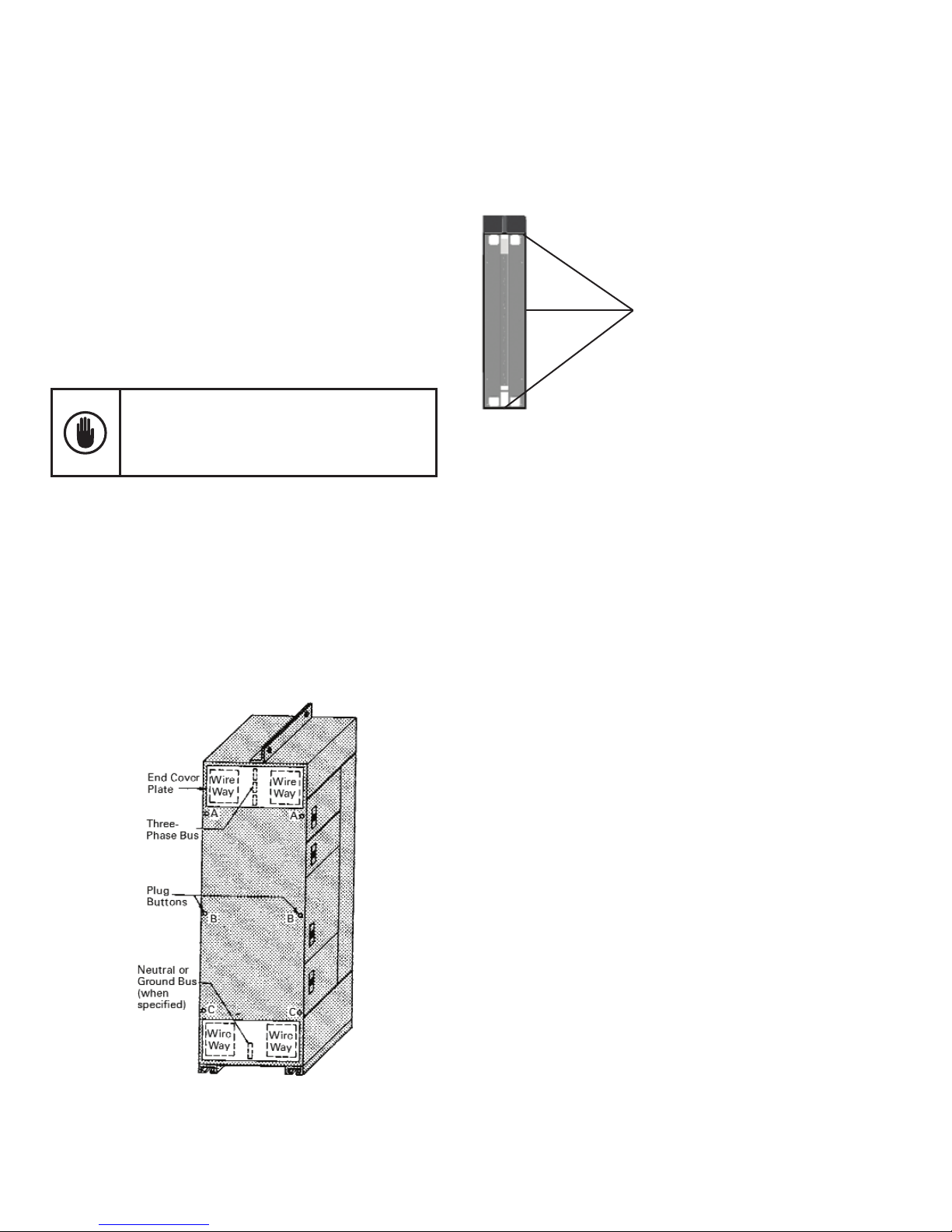
Positioning and Joining Sections
If groups of sections are to be joined together in a nal
lineup, remove the end cover plates and the plug buttons,
from the sides of the sections to be joined. Figure 10
shows the side views, with the end cover plates removed,
for 20-inch-deep sections with 2-inch (50.8 mm) and
4-inch (101.6 mm) bus bars.
Carefully check and remove dirt, dust or bits of packing
material from the interior of all sections. Use a brush,
soft cloth or vacuum cleaner.
Do not use compressed air to clean the equipment
if it contains moisture. Remove all hardware
packages, drawings and other items shipped with
the equipment. Check all nuts, bolts, and electrical
joints for tightness.
All cables entering the bottoms of sections should be
pulled through conduits to a point where they will be
accessible after the equipment is in place. Sections can
be moved to their nal position and properly leveled.
For Arc Resistant plenum-less design, the cables can
enter either through the front or rear aluminum ap on
top of the section.
For Type 12 and Arc Resistant enclosure, see Figure
10A for proper gasket in between the section splits. For
additional gasket material order part number 245A1888P5.
Gaskets
Figure 10A. Type 12 and Arc Resistant
gasket material between section splits
NEC Work Space
NEC Work Space is dened in Table 110.26(a) Working
Spaces. Included in these clearance requirements is the
step-back distance from the face of the equipment.
Table 110.26(a) provides requirements for clearances
away from the equipment, based on the circuit voltage
to ground, and whether there are grounded or ungrounded objects in the step-back space, or if there are exposed
live parts across from each other. The voltages to ground
consist of two groups: 0 to 150 and 151 to 600, inclusive.
Remember, where an ungrounded system is utilized, the
voltage to ground will be the greatest voltage between
the given conductor and any other conductor of the
circuit. For example, the voltage to ground for a 480-volt
ungrounded delta system is 480 volts.
Figure 10. Side view of a 20-inch-deep section showing the cover
plates, plug bottoms and joining points
11
See Figure 14 for general working clearance requirements.
Distances are measured from the live parts if the live
parts are exposed, or from the enclosure front if live
parts are enclosed. If any assemblies, such as switchboards or motor control centers, are accessible from the
back and expose live parts, the working clearance
dimensions would be required at the rear of the equipment,
as illustrated. Note that for Condition 3, where there is
an enclosure on opposite sides of the working space,
the clearance for only one working space is required.
Page 13
Evolution Series E9000 User Manual
plenum the conduit can be assembled on top of the
plenum. GE oers an additional pull box for higher conduit
space requirement. The Pull box can be assembled on
top of the incoming section.
Always remove top cover plates when drilling holes.
This prevents small metal chips from falling into the
panel and cause serious damage.
Figure 14. General Working Clearance Requirements
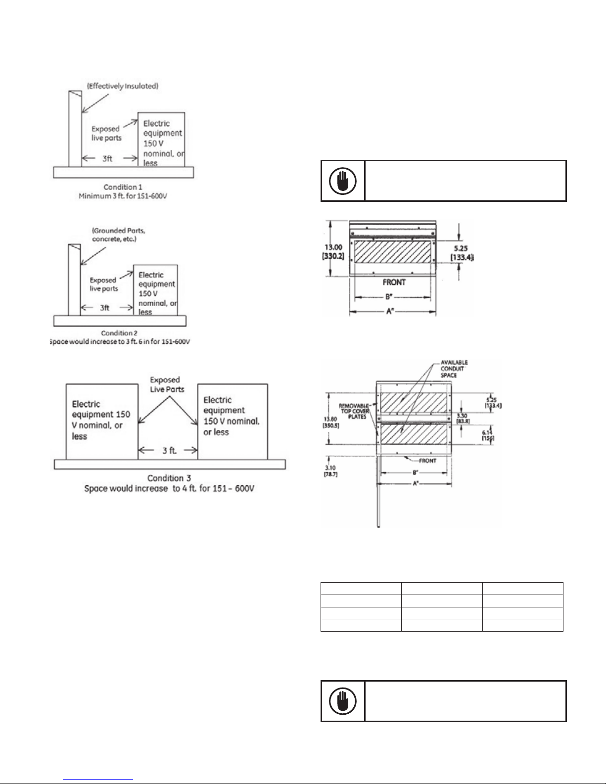
Installation of Top Entry Conduits
After the motor control center is in place and leveled, and
the sections are joined together, conduits can be brought
into the tops of sections as required. Figure 15 and
Figure 16 show the conduit entry space available at the
tops of standard sections. Refer to drawings furnished by
GE for deviations on specic installations. Note: Top rear
entrance should only be used with full rear accessibility.
Figure 15A. Top conduit entry space for 13-inch sections
Figure 15B. Top conduit entry space for 20-inch and 22-inch sections
Table 3. Dimensions for Figures 15 and 16
Width Dimension A Dimension B
20" 20" 17.56"
24" 24" 21.56"
30" 30" 27.56"
Equipment Wiring
For plenum-less Arc Resistant design, the conduits can
be brought into the tops of the sections through front
or rear aps as required. For Arc Resistant sections with
When pulling, bending, and terminating eld wiring,
avoid scraping, cutting or otherwise damaging
cable insulation or strands.
12
Page 14

Evolution Series E9000 User Manual
Exhaust Fan Installation for NEMA 1 Enclosure
Fan Assembly
Top Rear Cover Location
Figure 16A. Exhaust fan for NEMA 1 enclosure
High heat loss main bus splice joints and/or components,
including certain solid state power devices, may require
removal of excess heat to the MCC exterior environment.
This is accomplished by the utilization of exhaust fans.
Exhaust Fan Installation for UL Type 12 Enclosure
and Arc Resistant Vented Fan Shields
UL Type 12 Fan Assembly
Filter Assembly
Figure 16B. Exhaust fan for UL Type 12 enclosure
Arc Resistant
VFD Fan Shield
Exhaust fans, if required, are delivered to the installation
site as a separate shipping item. Fans must be unpacked,
checked for collateral damage, and installed over the top
rear conduit entry space of the appropriate MCC section.
Installation involves connecting two mated control power
harness ends for each fan assembly. One harness is
located within the fan assembly. The corresponding
mated harness end is coiled and secured inside the top
rear of the section being ventilated.
If, upon delivery, it is found that standard rear top section
covers are in place on the section requiring ventilation,
the covers must be removed and discarded. The exhaust
fan assembly can then be installed as shown in Figure 15A.
Note: For details on inlet lter maintenance, see Filter
Maintenance in Chapter 5.
High heat loss components, including certain solid state
power devices, may require removal of excess heat to the
MCC exterior environment. This is accomplished by the
utilization of exhaust fans mounted on unit doors along
with lters. These fans and lters are factory installed.
Note: In addition to using Type 12 exhaust fans and
lters, Arc Resistant design will also have a vented fan
shield on the exterior of the door. For details on inlet
lter maintenance, see Filter Maintenance in Chapter 5.
Main Incoming Power Cables
Refer to the motor control center drawings provided by GE
for the location of the main disconnect or incoming line
terminals and the direction (top or bottom) of cable entry.
Cable-bending room provided within the vertical section
will meet or exceed National Electrical Code requirements.
Incoming line sections are provided with cable supports.
Incoming cables must be rmly secured to withstand
the signicant forces that may be generated during a
short circuit .
13
Cables secured at each support, as illustrated in Figure
17 and Figure 18 (600A example), will adequately brace
cables for faults of 100K RMS symmetrical amperes,
Page 15

Evolution Series E9000 User Manual
based on horizontal bus bracing. However, cables
should always be secured at the rst support inside the
enclosure and at the support nearest to the incoming
terminals. Insulated bushings are also recommended at
conduit terminations.
Figure 17. Typical top entry of main cables to the
incoming-line lug compartment (600A shown)
Figure 18. Typical bottom entry or main cables to the
incoming-line lug compartment (600A shown)
Align the conduit linearly directly over or as close as
possible to the supports. Run the cable in a convenient
orientation, making sure the cable is located against
the supports before it connects to the cable terminals.
Lash the cable using the following procedure:
Wrap the line cables together and, if provided, tie
cables together with nominal 3/8-inch (9.5 mm) nylon
rope or rope having a minimum tensile strength of 2000
pounds (8896 N), at 6 inches (152 mm) and 12 inches
(305 mm) from the line terminals. Use ve wraps and
complete every additional 6 inches with ve wraps or
every 1 inch (25 mm) with one wrap. Use supplied cable
supports as desired. Refer to UL 891.
Individual Unit Wiring
Open the vertical wireway door(s) and the top and/or
bottom horizontal wireway hinged covers. All doors
can be removed, if desired, by extracting hinge pins or
removing the hinge.
When installing cables, be sure to not damage
the cable insulation on any sharp edges, such as
steel work or screws.
Where access to the rear of the section is available,
cables can be brought into the space behind the vertical
bus and brought forward into the front wire trough area
through any of the modular openings in the right-hand
steel support plate.
Wiring NEMA Type A Motor Control Centers
Use the following procedure to wire NEMA Type A MCCs:
1. Remove black plastic barrier closest to unit connection
points and remove knockouts as required.
2. Pull load cables near the unit to be wired. Measure
(allowing for cable bends), cut and strip the cables,
and feed them carefully through barrier knockout
into the unit. Terminate the cables on the feeder or
starter lugs provided in the unit. If aluminum wire is
used, coat the wire strands with an oxide-inhibiting
grease specically designated for use with aluminum
cable. Install plastic side barrier.
3. Pull the control wiring, then measure, cut, strip,
and terminate it on individual device terminals in
the unit.
4. When specied, an optional ground lug is provided in
each draw-out combination starter unit for terminating
a motor-frame grounding wire. (For larger starters,
the lug is mounted on the horizontal ground bus.)
5. Use cord or plastic ties to secure all wiring. Route the
wiring to avoid interference with moving parts and
to keep it away from heat-producing components,
such as resistors and fuses.
6. Verify that the connections on all devices and terminal
blocks are tightened to their proper torque values, as
listed on the label on the vertical wireway door.
14
Page 16

Evolution Series E9000 User Manual
Wiring NEMA Type B Motor Control Centers
Use the following procedure to wire NEMA Type B MCCs:
1. Remove black plastic barrier closest to unit connection
points and remove knockouts as required.
2. Pull load cables near the unit to be wired. Measure
(allowing for cable bends), cut and strip the cables,
and feed them carefully through barrier knockout
into the unit. Terminate feeder cables directly on the
lugs on the disconnect. Connect the motor leads at
the starter terminals if either of these conditions is met:
a. The motor control center is furnished as
“NEMA B-D wiring” (where D=Device) or
b. The starter is NEMA size 6 or smaller.
Connect the motor leads to the starter at the T1, T2,
and T3 terminals if these conditions are met:
a. The equipment is furnished as “NEMA B-T” wiring
and
b. The starter is NEMA size 2 or smaller.
Install plastic side barrier after power and control
wiring in Step 4 is complete.
Aluminum wire is not recommended for this product.
3. Pull the control wiring, then measure, cut, strip and
terminate it at the terminal blocks provided within
the unit. Optionally, control terminal blocks may be
pulled apart and the plastic knock-outs removed to
allow wiring outside the bucket. The terminal blocks
can then be placed back through the plastic knock-
out openings and reinstalled. This method allows
wiring to terminal blocks outside the connes of the
starter unit.
4. When specied, an optional ground lug is provided in
each draw-out combination starter unit for terminating
a motor frame grounding wire. (For larger starters,
the lug is mounted on the horizontal ground bus.)
5. Use cord or plastic ties to secure all wiring. Route the
wiring to avoid interference with moving parts and
to keep it away from heat-producing components,
such as resistors and fuses.
6. Verify that the connections on all devices and terminal
blocks are tightened to their proper torque values, as
listed on the label on the vertical wireway door.
Wiring NEMA Type C Motor Control Centers
Master terminal boards in NEMA Type C motor control
centers are provided in the larger top or bottom
horizontal wireway of each vertical section. (Refer to
the drawings provided by GE for the locations of master
terminal boards.) Figure 19 and Figure 20 show typical
Type C terminal board arrangements.
These terminal boards are connected at the factory to
control terminal blocks of plug-in units in each vertical
section. Wiring diagrams provided by GE show these
terminal points. These terminal blocks are also factory
wired to the T1, T2 and T3 motor-lead terminals for each
NEMA size 1–2 starter unit in each vertical section.
Field connections to these control and load terminals
should be made at the master terminal boards.
Make eld connections to all feeders and motor loads
for starters larger than NEMA size 2 as described for
NEMA Type B motor control centers.
Optional grounding lug can be provided in each Plug-in
unit if vertical ground bus is specied.
Figure 19. Typical Type C terminal board at the top of a section
15
Figure 20. Typical Type C terminal boards in multiple sections
Page 17

Evolution Series E9000 User Manual
Wiring Between Sections
Figure 21 shows the dimensions of side cutouts in each
vertical section for wiring between sections. Cross-wiring
can be accomplished at both the top and bottom of
sections. 20"or 22" deep vertical sections accessible
from the rear can be cross-wired in the open rear area,
with the wiring brought forward through oval openings
in the rear of the vertical wireway.
Figure 21. Side cutout dimensions on 13", 20", 22" and 25"
Terminal Blocks
The new style terminal blocks are mounted on a metal
rail located at the bottom of the unit, as shown in
Figure 22. The terminal block easily slides into position
from either side of the mounting rail.
If rear access is used, a rear main bus barrier is
a required option.
Figure 22. Mounting the terminal block
Installation of Standard Motor Control Center Units
Any unit ordered separately is shipped complete with
the door and associated hardware. If the space available
in the vertical section is greater than the new unit
height, order a blank ller door with hinge hardware and
a snap shelf. See the renewal parts bulletin for ordering
blank doors and gasket materials. The gasket material
lines the inner perimeter of the section. Figure 23 shows
the gasket material mounted to the outside of the door.
Gasket
Figure 23. Type 12 and Arc Resistant gasket material
installed in a MCC section
16
Page 18

Evolution Series E9000 User Manual
Use the following procedure to install a motor control
center unit:
1. Attach the door hinges to the left side of the
section, line up the door with the hinges, then insert
the hinge pins to secure the door. (For Type 12
enclosures, mount the gasket on hinge side. See
Figure 23.)
2. Start 1/4-20 thread rolling screw in left hinge rail
just below the location for the shelf shown in
Figure 24.
3. At the same time, hook the shelf into the rear wing
plate and onto the started 1/4-20 screw from
step 2.
4. Snap the shelf into the shelf support on the vertical
wireway side of the case and tighten the 1/4-20
screw from step 2.
5. Lower the right side of the shelf and snap the two
detents in the right-side ange into the two holes
in the side of the vertical wiring trough barrier, as
shown in Figure 24. Swivel the shelf hold-down
bracket and grounding spring into place and tighten
the lower case hinge.
6. Examine the new unit carefully, front and rear, to
ensure that all screw terminals are tight, all foreign
material and packing are removed, and the insulating
barriers are secure.
7. The unit disconnect must be in the OFF position
before the unit can be inserted into the vertical
section.
8. If necessary, rotate the latches at the top and
bottom of the unit so that they are horizontal.
9. Remove the snap-in cover over the vertical bus
stab-in openings at the appropriate installation
location for the unit to be installed.
10. Lift the unit and place its base on the front horizontal
surface of the snap-in shelf.
11. Slide the unit into the vertical section, then push
at the top and bottom until the stabs are fully
engaged with the vertical bus.
12. Rotate the latches at the top and bottom of the
unit clockwise to engage the latches with the
horizontal shelves above and below the unit.
See Figures 25 and 26.
13. Verify the operation of the disconnect handle and
safety interlocks, as described later in this manual.
2
3
4
Figure 24. View of the snap-in shelf as installed
Latches
Figure 25. Unit disconnect in the OFF position. Two quarter-turn
door latches are located at the top.
17
Figure 26. Quarter-turn latch located at the bottom of the unit
Page 19

Evolution Series E9000 User Manual
Removal of Draw-Out Motor Control Center Units
Some units may still have control power applied
from an external source after the unit disconnect
has been switched to the OFF position. Be extremely
careful when removing units from any motor control
center. Failure to observe this precaution can result
in serious injury or death.
The procedure for removing a motor control center unit
is generally the reverse of the procedure for installing a
unit:
1. Ensure that the unit disconnect is in the OFF position,
as shown in Figure 25. For AFM units, ensure that
the stabs are in the “DISENGAGED” position with
indicators showing green.
2. Turn the door latches a quarter turn, open the unit
door and the vertical wiring trough door.
3. Disconnect all eld-connected wiring by separating
the pull-apart terminal blocks in the unit. Pass the
terminal blocks and wires into the vertical wiring
trough. Note that the plastic knock-outs in the vertical
wireway barrier can be removed and left within the
vertical wireway, with the eld wiring, rather than
threading the wiring and terminals back through
the knock-out.
4. Disconnect any other eld-installed wires that are
terminated in the unit. Remove these wires from
the unit, tag them (if desired), and leave them in the
vertical wireway adjacent to the unit.
Operating Handles, Door Interlocks and
Padlocking Provisions
All Evolution motor control center units are furnished
with disconnect operating handles that are integral
to the unit structure. The position of the disconnect
(ON–OFF for switches or ON–TRIP–OFF for circuit
breakers) is indicated by the position of the operating
handle. The operating handle is interlocked with a catch
on the inside of the unit door to prevent inadvertent
opening of the door when the disconnect is in the ON
position, as shown in Figure 27. Switching the handle
to OFF allows access to the interior of the unit.
Each disconnect operating handle is equipped with
an interlock that prevents opening the door when the
disconnect is ON.
A concealed screw can be turned counterclockwise
with a 5/32” Allen wrench to defeat the door interlock
and access the breaker disconnect when ON, as shown
in Figure 28. Only qualied personnel should be allowed
to defeat the interlock.
Be careful with any eld wiring removed from a
unit that may become energized. Such wiring
must be adequately insulated to avoid inadvertent
contact. Failure to observe this precaution can
result in serious injury or death.
5. Turn the latches at the top and bottom of the unit a
quarter turn counterclockwise to release the unit.
These latches are shown in Figure 25 and Figure 26.
6. Pull unit out to remove it, being extremely careful to
support its weight as it is fully withdrawn.
7. The door over the withdrawn unit can be latched closed.
8. If desired, a blank door can be ordered to cover the
unused opening. (For large unit spaces, two blank
doors and a horizontal unit shelf may be required.)
Figure 27. Door-interlock feature that prevents access to the
disconnect when the power is ON
Figure 28. Concealed screw used to defeat the door interlock
18
Page 20

Evolution Series E9000 User Manual
Figure 29. The door cannot be opened when the disconnect is ON
The disconnect is also equipped with a padlocking
provision, so that the operating handle can be locked in
the OFF position. The handle can also be drilled to
accommodate one padlock to secure it in the ON
position. In either case, the unit cannot be withdrawn
because of interference between the padlock(s) and door.
CAUTION: The friction of Type 12 gasketing can
prevent the breaker disconnect operating handle from
returning to the full ON position. Prior to servicing,
conrm breaker disconnect is in the OFF position.
Operating Handle
The operating handle must be moved out of the way
to access the breaker disconnect. Make sure that the
disconnect operating handle is in the OFF position.
Open the door, then remove the mounting screw
securing the base of the handle to the side of the unit,
as shown in Figure 31. The handle can then be rotated
up and out of the way, as shown in Figure 32, allowing
access to the breaker.
Final commissioning: Verify that all doors are
properly latched and interlocked prior to energizing.
Table 3. Weight and heights of CB basic with CPT
Plug-in Units,
No Door
NEMA Size 1 FVNR 35 12
NEMA Size 2 FVNR 37 12
NEMA Size 3 FVNR 53 18
NEMA Size 4 FVNR 62 24
NEMA Size 5 FVNR 125 36
Estimated Weight
(lbs)
Minimum Height
CAUTION should be used when removing or
installing units consider the weight in table above.
Two persons may be required or the assistance of
a lifting devices. See page 21 for suggested lifts.
Figure 31. Removing the operating handle mounting screw
(Inches)
Figure 32. Rotating the operating handle to access the breaker
19
Page 21

Evolution Series E9000 User Manual
Pilot Bracket and Door
The pilot device door can be removed by lifting straight
o per Figure 33. Also, the metal bracket can be removed
by loosening mounting screws and removing bracket.
Figure 33. Grasp the center of the door
Figure 34. Pilot device bracket locking bracket in door
The pilot device bracket in is locked in place using the
door mounted locking bracket shown in Figure 34.
All pilot device brackets for Arc Resistant MCCs are
metallic (both standard and AFM units). Standard
E9000 MCCs utilize a plastic pilot device bracket.
NEMA 3R Outdoor Enclosure Installation
NEMA 3R Installation Instructions
1. Remove left rear cover on right shipping module (Figure 1.) Save
the screws for later reassembly of the cover. Note that the left
module right rear cover has a ange that will be underneath the
removed covered with it is replaced. This provides an overlapping
connection in the rear of the two spliced modules (Detail C).
2. Slide adjoining shipping modules as close together as possible
while carefully aligning the modules front-to-back.
3. Join shipping modules together using (4 sets) 1/2 hardware
(front only). Hardware kits shipping with modules.
4. Assemble bus splices per splice instructions (included in splice
kit).
5. Install wireway transition channel barrier by sliding it though
the 5 x 5 wireway cutout and attaching it using (1) 1/4-28 x 3/8
thread rolling (Figure 3).
6. Re-attach right, rear cover by re-attaching 1/4-20 x 5/8 sealing
screw (Detail C).
7. Attached center cap using (8) 1/4-20 x 5/8 thread rolling screws
(Figure 1).
Figure 34A. Arc Resistant metallic pilot device bracket
Notes:
1. 3-inch oor members can be installed similarly to standard
MCC or members.
2. Module doors can be removed by removing 1/4-20 x 3/8 thread
rolling screws from door hinge bracket (Detail D).
20
Page 22

Evolution Series E9000 User Manual
21
Page 23

Evolution Series E9000 User Manual
Chapter 4 – Operation
Preparing for Initial Operation
In addition to the normal circuit checking after wiring
is completed, the following specic actions should be
taken before energizing the equipment:
1. Check and tighten any electrical connections, such as
lugs and bus splices that may have loosened during
shipment, handling and installation. Torque values are
provided on or adjacent to components or lugs. See torque
labels in MCC vertical wireway door. Visually check
that all latches on Arc Resistant enclosures are engaged.
2. Operate each magnetic device by hand to verify that
all moving parts operate freely. Check all electrical
contacts for proper operation.
3. Current transformers are shipped with a shunt
across the secondary if the circuit is not complete.
Remove the shunt after completing the connections
to the transformer secondary.
4. Verify that the horsepower and voltage rating of the
motor agree with the rating stamped on the starter
unit to which it is connected.
5. Check each overload heater or electronic overload
relay setting against the motor full-load current.
Check current transformer-operated overload
relays to be certain that overload heaters are
in place. Do not operate starters without
overload protection.
the operating handle down beyond the OFF position.
The operating handle should move upward to the
OFF position after the breaker has been reset. After
the reset, turn the circuit breaker ON and then OFF
to conrm proper operation.
10. Visually check all units and enclosures to ensure
that electrical spacings have not been reduced
because of shipping and handling actions.
11. Verify that the motor control center enclosure and
units are grounded.
12. Replace all protection barriers and panels that have
been removed during installation.
13. Carefully clean the equipment interior with a clean
cloth, soft brush or vacuum cleaner to remove all
metal chips, dust, wire and other debris.
14. After taking precautions to prevent accidental contact
with the motor control center buswork, conduct the
following insulation-resistance test with a 1000 Vdc
(Megger) tester. With all disconnects in the OFF position,
• Apply voltage between all phase pairs.
• Apply voltage between each phase and ground.
All readings should be 1 megohm minimum; typical
values will be 50–100 megohm but may vary based
on humidity.
Similarly, test individual feeder and motor circuit
wiring (eld wiring) as each set of conductors is pulled
into the motor control center, before terminating
the conductors at either end.
6. Check all circuit breaker trip settings and fuse ratings
against the drawings supplied with the equipment.
a. If trip settings must be changed, use the GE rating
plug extractor tool (catalog number TRTOOL) to
remove rating plugs from Spectra circuit breakers.
b. See the startup procedure following information
regarding instantaneous trip settings on magneticonly circuit breakers.
Do not exceed the long-time and/or instantaneous trip settings stipulated in the National
Electrical Code and as identied in the overload
heater selection tables in this manual.
7. Check all pneumatic or motor-driven timers for
proper time-interval settings.
8. Manually operate all branch-circuit disconnects and
verify proper operation of disconnects and door
interlocks.
9. Where applicable, manually trip all circuit breakers
to verify that operating handles move freely to the
TRIP indicating position. With the door closed and
latched, reset each tripped circuit breaker by pushing
15. With all disconnects OFF, close and latch all doors
and secure all external covers.
16. For AFM Units, ensure that all visual indicators are
showing “RED” to indicate “ENGAGED” stab position
and “OPEN” shutter position.
Initial Operation of the Motor Control Center
Because of problems that may occur during
the initial energizing of the motor control
equipment, only qualied personnel should
carry out this startup procedure.
Use the following procedure for initial startup of the
motor control equipment. Be sure that the steps in the
previous section, Preparing for Initial Operation, have
been completed.
1. Ensure that all doors are closed and latched and all
external covers on the motor control center are
secured. Visually check that all latches on Arc Resistant
enclosures are engaged.
2. Verify that all main and branch disconnects within
the motor control center are OFF.
22
Page 24

Evolution Series E9000 User Manual
3. Verify (with an insulation-resistance tester) that all
main incoming feeders to the motor control center
are adequately insulated.
4. Close the upstream feeder to energize the motor
control center.
5. Close the main disconnects, if any, at the motor
control center.
6. Close each branch-circuit disconnect or feeder at
the motor control center. For AFM Units, ensure that
all visual indicators are showing “RED” to indicate
“ENGAGED” stab position and “OPEN” shutter position.
7. Operate each motor starter individually to verify satisfactory operation, including the following parameters:
• Motor rotation
• Pilot light indication
• Electrical interlocking
• Acceleration and sequence timing
Power-factor correction capacitors on
individual motor circuits should be temporarily
disconnected during startup.
Door Closing Procedure of Pilot Device Bracket,
Extension Bubble Door for Some GP/FP Drives
E9000 MCC units
Variable
Frequency
Drive
Extension
Bubble
Figure 35. Door, pilot device bracket and extension bubble
in open position
PD Bracket
8. Adjust instantaneous settings on magnetic-only circuit
breakers and/or fuse sizes and overload heater
selections to achieve proper motor and branch circuit
protection. (See NEC Article 430.52.) Since the
adjustable trip setting on magnetic-only circuit
breakers is factory set at the minimum trip position,
nuisance tripping may occur on initial motor starting.
Increase the trip setting in increments until tripping
no longer occurs during motor starting. Do not exceed
the maximum trip settings given in overload relay
tables in this publication. All adjustable overloads
are also factory set at minimum. Check motor
name-plate data and set overloads accordingly.
Figure 36. Partially close the pilot device bracket
and extension bubble as shown
23
Page 25

Evolution Series E9000 User Manual
Figure 37. Partially close the door as shown
Locking Bracket
Extension Bubble
Door Door Cut Out
Gasket
Figure 38. Adjust the pilot device bracket and extension bubble lip
so it enters in between the keeper bracket and inside of the door
1/4 Turn Latch
Figure 39. Close the door completely and turn the 1/4-turn latches
24
Page 26

Evolution Series E9000 User Manual
Chapter 5 – Maintenance
Equipment Maintenance
De-energize all equipment before performing any
maintenance operation. There may be voltage present
within the equipment from remote sources, even
though all main- and branch-circuit disconnects have
been opened at the equipment. Failure to observe
this precaution can result in serious injury or death.
The customer should prepare a maintenance program
consisting of a schedule and checklist matrix listing items
to be periodically examined on the installed equipment.
The frequency and extent of the maintenance activities
will vary depending on such factors as equipment usage
and environmental conditions. In any maintenance
program the following actions should be included:
1. Remove accumulated dust and dirt with a soft
cloth, brush or vacuum cleaner.
2. Wipe clean all main bus insulators and vertical bus
barriers.
3. Inspect main and vertical bus joints and main bus
supports and tighten, if necessary. Refer to Table 1
for torque specications.
4. Inspect all wiring from units for deterioration of
insulation.
5. Remove draw-out units and check stabs and all
unit wiring. Remove accumulated dust from
horizontal shelves and the areas around stabs.
6. Check all starter contacts. They need only be
replaced when nearly all the silver tip is gone and
the contact tip support is exposed. Do not le the
contacts. Filing or otherwise dressing the contacts
only results in lost tip material and reduces starter
life. See GE publication GET-6915A for questionable
contact appearance.
7. Check all unit wiring for deterioration of insulation
and tighten all connections.
8. Visually check meters and instruments. Check critical
instrument calibrations.
9. Check all unit door interlocks for proper operation.
10. Check all indicating lights and replace, as required.
11. If fuse replacement is necessary, always install the
same type and rating as the fuses furnished with the
motor control center. Fuse designs may be mechanically equivalent but not electrically equivalent. They
may not have the same short-circuit withstand and
current-limiting ability.
Inlet Filter Maintenance
Filter inspection and cleaning must be carried out every
six months or more frequently as per your established
maintenance plan. The frequency of lter maintenance
or replacements should be determined individually,
depending on dust accumulation and operating period.
Note: A soiled lter mat will cause the temperature to
rise inside the enclosure. The lter mat can be regenerated by washing or blowing out.
Arc Resistant Maintenance
If a unit is removed from an Arc Resistant section for
maintenance, a solid blank door should be used to
cover the opening in order to maintain arc resistance.
Control Power
The option to have control power or test power during
service is a functionality that has been provided with
the Arc Resistant introduction of the LV MCC. This is a
necessary requirement in order to check functions during
service such as pilot lights and devices. This is intended
to standardize the oerings when a customer orders
common control power on the MCC. The two options we
provide allow for 1) customer supplied 120VAC power
or 2) self-contained control power within the MCC.
The key switch is utilized to operate the control power
when the stabs are disengaged. The key switch is turned
“On” allowing the secondary control power to be utilized.
The key switch should be “O” during normal operation
of the MCC.
Control Power Fusing
Control fuses are front accessible except in the 6-inch
compact starter. Remove 6-inch FVNR starter for
maintenance. Fuses are located on the side, as shown
in Figure 40.
25
Figure 40. Fuse location
Page 27

Evolution Series E9000 User Manual
Suggested Maintenance Tools
The following tools are recommended for performing
maintenance operations:
• GE Spectra circuit breaker rating plug removal tool,
catalog number TRTOOL (see Figure 41).
• GE pilot light and push button removal tool, catalog
number GEN-1684A (see Figure 42).
• EntelliGuard TU Digital Test Kit, catalog number
GTUTK20 (see Figure 43). The Test Kit may also be
used to temporarily defeat the ground-fault function
during primary injection (high-current test set).
• Manual racking handle, catalog number 110C2073G1
(see Figure 44).
• Remote racking device, catalog number 190B3523G1
(see Figure 45).
• Allen wrench in size 5/32 inch or #4 metric for
defeating the door interlock.
Rearrangement of units must follow the following
loading rules: 80% of the feeder trip or fuse clip rating, plus 100% of the starters full load current, plus
25% of the largest motor full load current. Do not
exceed the vertical bus rating label on each section.
Replacing or Adding Breaker Accessories to
Plug-in E or F frame Circuit Breaker
Use the following procedure to replace a circuit breaker
in a motor control center.
1. Turn the power o.
2. Remove the unit from the motor control center.
3. Remove line and load cables (not required for
accessories only)
4. Remove the toggle holding plate (toggle needs to be
in the ON position, UP)
5. Remove the top four screws in top plate holding the
breaker assembly (not required for accessories only).
6. Remove three front breaker screws from assembly.
7. Slide the breaker down and out.
8. Install the new breaker by following this procedure in
the reverse order. Torque all electrical connections.
Figure 41. Rating plug
removal tool, catalog number
TRTOOL
Figure 42. Pilot light and
pushbutton removal tool,
catalog number GEN-1684A
Figure 43. EntelliGuard Trip
Unit Digital Test Kit, catalog
number GTUTK20
Figure 44. Manual racking
handle, catalog number
110C2073G1
Replacing a Control Power Transformer
Mounted Under Disconnect
Use the following procedure to replace a control power
transformer mounted under a disconnect.
1. Turn the power o.
2. Remove the saddle unit from the motor control center.
3. Remove the top plate from the saddle unit.
4. Remove the handle assembly, as described on page 15.
5. Remove line and load cables.
6. Loosen the screws securing the disconnect assembly
to the back plate and slide the assembly out.
7. Disconnect the transformer power and control leads.
8. Remove the transformer mounting screws and lift
out the transformer.
9. Install the new transformer by following this procedure
in the reverse order. Torque all electrical connections.
Figure 45. Remote racking
device, catalog number
190B3523G1
26
Page 28

Evolution Series E9000 User Manual
Replacing a Compact Starter (1/2X)
Use the following procedure to replace the starter.
1. Turn the power o.
2. Remove the saddle unit for the motor control center.
3. Remove the pilot device bracket (it is not required
to remove control wiring)
4. Remove overload relay.
5. Use DIN rail release to gain access to line side wiring
of contactor, remove line wires.
6. Reverse to install new starter.
Suggested Lifts
Example: GE Model No. 55B534913P1
• All welded construction
• Positive lock winch system
• 500 lb. capacity
• Raised height 58"
• Lowered height 3-1/8Æ
• 20" X 20" deck size
• 10" load center
• 2" X 6" molded-on-rubber casters
Publications Available from GE
Order any of the following publications from your
nearest GE representative, authorized distributor, or
from the following address:
GE
Distribution Services
PO Box 2913
Bloomington IL 61702-2913
Phone: 309-664-1513
Fax: 309-662-6990
The following instructions are available.
300 Line Starter
GEH-5190 – NEMA Size 1 FVNR
GEH-4774 – NEMA Size 2 FVNR
GEH-4806 – NEMA Size 3 FVNR
GEH-4807 – NEMA Size 4 FVNR
GEH-4839 – NEMA Size 5 FVNR
GEH-5198 – NEMA Size 6 FVNR
GEH-5190 – NEMA Size 1 FVR & 2 Speed
GEH-4775 – NEMA Size 2 FVR & 2 Speed
GEH-4806 – NEMA Size 3 FVR & 2 Speed
GEH-4807 – NEMA Size 4 FVR & 2 Speed
GEH-4839 – NEMA Size 5 FVR & 2 Speed
GET-6915A - Tech Info.- Contact Appearance
Arc Flash Mitigation Units
DEI-007 – Remote Racking System Instructions
DEI-009 – AFM Retrot Assembly Instructions
DEI-010 – Manual Racking Handle Instructions
C-2000 Contactors
GEH-6263 – CL02, CL025
GEH-6264 – CL045
GEH-6265 – CL08
GEH-6266 – CL10
GEH-6350 – CK08
GEH-6227 – CK095
GEH-6228 – CK10B, CK11B, CK12B
Solid State Starters
DET-787 – ASTAT-BP
DEH-40397 – ASTAT-CD Plus
Relays
GEH-4115 – CR120B
GEH-6435 – ECM
AF600 Drives
DET-609 – AF-600FP Operating/Installation
DET-620 – AF-600FP Programming Guide
DET-623 – AF-600 FP/AF-650 GP
DET-624 – AF-600FP / AF-650 GP Probus DP
DET-633 – AF-600 FP Analog I/O Instructions
DET-635 – AF-600 FP / AF-650 GP External DC Supply
DET-607 – AF-650 GP Operating/Installation
DET-618 – AF-650 GP Programming Guide
Smart Relays
MM300
GEK-113022 – Instruction Manual
GEK-113336 – Quick Start Guide
GEK-113392 – Communication Guide
MM200
GEK-113400 – Instruction Manual
GEK-113401 – Quick Start Guide
GEK-113402 – Communication Guide
Spectra Circuit Breakers
DET-244 – Special Lugs
GET-7002 – Application and Selection
GEZ-7754 – Spectra Time-Current Curves
Power Break II Insulated-Case Circuit Breakers
DEH-4568 – GTU Test Kit
GEH-6270 – PBII Instruction Manual
DEH-4567 – EntelliGuard Instruction Manual
DES-096, 097, 098, 099, 100 – EntelliGuard TU Trip Curves
27
Page 29

Evolution Series E9000 User Manual
Renewal Parts
Because of the variety of components furnished in the
E9000 motor control center, the suggested spare parts
will vary. You should consider maintaining an adequate
supply of the following components as spares:
• Overload heaters
• Power and control circuit fuses
• Replacement starter contact kits
• Starter coils
• Pilot lights
• Push buttons
• Circuit breakers and fusible switches
• Extra draw-out terminal blocks
• Complete starters and/or spare units as warranted
by installation needs.
Your GE account manager will be glad to assist you in
preparing a recommended parts list for your installation.
Ordering Additional or Replacement Parts
The following information is needed for supplying the
proper equipment:
1. All data on the motor control center master nameplate
2. If the unit is to be a duplicate of an existing unit, all
data on that unit’s nameplate, located on the right
side of the unit
3. NEMA control center class: I or II
4. NEMA wiring type: A, B or C
5. NEMA enclosure type: 1, 1 Gasketed, 1-HG (heavy
gasketed) 2, 3R or 12
6. Power supply characteristics:
• Voltage
• Number of phases
• Frequency in Hz
7. Control power voltage and frequency in Hz
8. Nameplate designation and title
9. Motor characteristics:
• Horsepower rating
• Speed in RPM
• Temperature rise in °C
• Full-load current in amperes
• Accelerating time in seconds
• Service factor
10. Disconnect characteristics:
• Fusible switch rating (A), fuse type, and clips
• Circuit breaker frame size and current rating (A)
11. NEMA starter size: 1, 2, 3, 4, 5, 6 or 7
12. Starter type: FVNR, FVR, RVNR, 2-speed winding
and accessories:
• Push buttons: start-stop, forward, reverse, up, down
• Transfer switch: H-O-A
• Pilot lights: quantity, color and type
• Interlocks: quantity of NO and NC
• Control power transformer
13. Unit X height or space available
14. Are horizontal shelves or other parts required?
15 Circuitry
16. All other modications
Other Information
For other information, refer to the nearest GE sales oce
and give full details, including equipment nameplate data.
Nameplates are prominently displayed on the motor
control center lineup and contain such details as service,
voltage, frequency, factory order number. Similar nameplates are mounted on each motor control center unit.
www.geindustrial.com
28
Page 30

Evolution Series E9000 User Manual
Chapter 6 –Overload Heaters
Heaters for Ther-Mag Circuit Breaker Controllers
For continuous-rated motors with a service factor of
1.15 to 1.25, select the appropriate heaters for the
motor full-load current. For continuous-rated motors
with a service factor of 1.0, multiply the motor full-load
current by 0.9 and use this value to select heaters.
Overload relay tripping current in 40°C ambient is the
minimum value of full-load current multiplied by 1.25.
Provide short-circuit protection in accordance with the
National Electrical Code.
Overload relays with automatic reset may automat-
ically start a motor connected to a two-wire control
circuit. When automatic restarting is not desired,
use a three-wire control circuit.
Circuit breaker tripping may be an indication that
a fault current has been interrupted. To provide
continued protection against re or shock hazard, examine all current-carrying parts and other
components of the motor controller and replace any
damaged components. If heater burnout occurs,
the complete overload relay must be replaced.
Size 0 and 1 (Standard and Ambient Comp.)
Motor Full-
Load Amps
3-Ph, 3 Heater
.41-.45 C054A 4.96-549 C592A
.46-.49 C060A 5.50-5.91 C630A
.50-.53 C066A 5.92-6.47 C695A
.54-.59 C071A 6.48-7.20 C778A
.60-.65 C078A 7.21-8.22 C867A
.66-.76 C087A 8.23-8.72 C955A
.77-.84 C097A 8.73-9.67 C104B
.85-.93 C109A 9.68-10.4 C113B
.94-1.04 C118A 10.5-11.0 C125B
1.05-1.15 C131A 11.1-12.4 C137B
1.16-1.27 C148A 12.5-13.2 C151B
1.28-1.39 C163A 13.3-15.4 C163B
1.40-1.55 C184A 15.5-17.1 C180B
1.56-1.73 C196A 17.2-18.0 C198B
1.74-1.89 C220A
1.90-2.05 C239A
2.06-2.28 C268A 17.2-18.1 C198B
2.29-2.47 C301A 18.2-20.0 C214B
2.48-2.79 C326A 20.1-21.5 C228B
2.80-3.31 C356A 21.6-22.5 C250B
3.32-3.70 C379A 22.6-23.9 C273B
3.71-4.06 C419A 24.0-26.3 C303B
4.07-4.47 C466A 26.4-27.0 C330B
4.48-4.95 C526A
29
Heater
Number
CR123
Motor Full-
Load Amps
3-Ph, 3 Heater
Size 1
Heater
Number
CR123
Size 2 (Standard and Ambient Comp.)
Motor Full-
Load Amps
3-Ph, 3 Heater
5.48-5.85 C630A 16.8-17.9 C180B
5.85-6.47 C695A 18.0-18.7 C198B
6.48-7.35 C778A 18.8-20.4 C214B
7.36-8.06 C867A 20.5-22.7 C228B
8.07-9.03 C955A 22.8-24.7 C250B
9.04-9.61 C104B 24.8-26.3 C273B
9.62-10.5 C113B 26.4-29.5 C303B
10.6-11.6 C125B 29.6-32.5 C330B
11.7-12.5 C137B 32.6-36.7 C366B
12.6-13.6 C151B 36.8-41.9 C400B
13.7-16.7 C163B 42.0-43.2 C440B
Heater
Number
CR123
Motor Full-
Load Amps
3-Ph, 3 Heater
43.3-45.0 C460B
Size 3 (Standard and Ambient Comp.)
Motor Full-
Load Amps
3-Ph, 3 Heater
19.0-19.3 F233B 17.8-18.4 F233B
19.4-22.1 F243B 18.5-21.1 F243B
22.2-23.4 F270B 21.2-22.1 F270B
23.5-27.0 F300B 22.2-26.1 F300B
27.1-29.1 F327B 26.2-28.0 F327B
29.2-31.8 F357B 28.1-31.3 F357B
31.9-33.9 F395B 31.4-33.3 F395B
34.0-37.6 F430B 33.4-34.3 F430B
37.7-41.9 F487B 34.4-40.9 F487B
42.0-47.7 F567B 41.0-44.7 F567B
47.8-52.1 F614B 44.8-51.0 F614B
52.2-55.8 F658B 51.1-52.0 F658B
55.9-59.7 F719B 52.1-55.4 F719B
59.8-68.1 F772B 55.5-63.3 F772B
68.2-71.5 F848B 63.4-66.1 F848B
71.6-78.2 F914B 66.2-73.5 F914B
78.3-87.5 F104C 73.6-82.2 F104C
87.6-90.0 F114C 82.3-90.0 F114C
Heater
Number
CR123
Motor Full-
Load Amps
3-Ph, 3 Heater
Size 4 (Standard and Ambient Comp.)
Motor Full-
Load Amps
3-Ph, 3 Heater
27.1-32.2 F357B 28.8-32.0 F357B
32.3-34.0 F395B 32.1-34.2 F395B
34.1-36.8 F430B 34.3-36.7 F430B
36.9-44.6 F487B 36.8-43.9 F487B
44.7-48.4 F567B 44.0-46.6 F567B
48.5-53.9 F614B 46.7-52.6 F614B
54.0-57.4 F658B 52.7-55.6 F658B
57.5-60.0 F719B 55.7-58.7 F719B
60.1-69.5 F772B 58.8-67.1 F772B
69.6-71.7 F848B 67.2-70.6 F848B
71.8-79.9 F914B 70.7-76.3 F914B
80.0-92.3 F104C 76.4-88.7 F104C
92.4-97.0 F114C 88.8-93.4 F114C
97.1-108 F118C 93.5-105 F118C
109-118 F133C 106-114 F133C
119-131 F149C 115-128 F149C
132-135 F161C 129-131 F161C
Heater
Number
CR123
Motor Full-
Load Amps
3-Ph, 3 Heater
132-135 F174C
Heater
Number
CR123
Heater
Number
CR123
Heater
Number
CR123
Page 31

Evolution Series E9000 User Manual
Size 5 (Standard and Ambient Comp.)
Motor Full-
Load Amps
3-Ph, 3 Heater
109-118 C592A 185-200 C104B
119-128 C630A 201-221 C113B
129-138 C695A 222-237 C125B
139-155 C778A 238-262 C137B
156-168 C867A 263-270 C151B
169-184 C955A
Heater
Number
CR123
Motor Full-
Load Amps
3-Ph, 3 Heater
Heater
Number
CR123
Heaters for Mag-Break® Controllers
The Mag-Break protector is factory adjusted to the
minimum trip setting
To maintain overload, short-circuit, and ground-
fault protection, use the following instructions
to select heaters and to adjust the Mag-Break
trip setting.
For continuous-rated motors with a service factor of
1.15 to 1.25, select the appropriate heaters for the
motor full-load current. For continuous-rated motors
with a service factor of 1.0, multiply the motor full-load
current by 0.9 and use this value to select heaters.
Use the heater table to verify that the Mag-Break and
current limiter rating is correct for the motor full-load
current. Then set the Mag-Break trip setting to the
recommended value.
If the Mag-Break trips during motor startup, increase
the trip setting by one step at a time until the motor
can be consistently started. Do not exceed the maximum
trip setting shown in the heater table.
Overload relay tripping current in 40° C ambient is the
minimum value of heater full-load current multiplied
by 1.25.
Circuit breaker tripping may be an indication that
a fault current has been interrupted. To provide
continued protection against re or shock hazard,
examine all current-carrying parts and other
components of the motor controller and replace
any damaged components. If heater burnout occurs,
the complete overload relay must be replaced.
Size 0 and 1 (Standard)
Motor Full-
Load Amps
3-Ph, 3 Heater
.65-.74 C087A 3 LO LO
.75-.84 C097A 3 LO LO
.85-.92 C109A 3 LO 1
.93-1.02 C118A 3 LO 1
1.03-1.10 C131A 3 LO 2
1.11-1.23 C148A 3 LO 2
1.24-1.38 C163A 3 LO 3
1.39-1.49 C184A 3 LO 4
1.50-1.67 C196A 3 1 4
1.68-1.79 C220A 3 1 5
1.80-1.98 C239A 3 1 6
1.99-2.24 C268A 3 2 7
2.25-2.43 C301A 3 3 8
2.25-2.43 C301A 7 LO 1
2.44-2.75 C326A 7 LO 2
2.76-3.25 C356A 7 LO 3
3.26-3.43 C379A 7 LO 4
3.44-4.03 C419A 7 1 4
4.04-4.43 C466A 7 1 5
4.44-4.94 C526A 7 2 6
4.95-5.36 C592A 7 2 7
5.37-5.77 C630A 7 3 6
5.37-5.77 C630A 15 LO 2
5.78-6.35 C695A 15 LO 2
6.36-6.92 C778A 15 LO 3
6.93-7.99 C867A 15 LO 3
8.00-8.47 C955A 15 1 4
8.48-9.19 C104B 15 1 5
9.20-10.0 C113B 15 1 6
10.1-10.7 C125B 15 2 6
10.8-12.0 C137B 15 2 7
10.8-12.0 C137B 30 LO 2
12.1-12.9 C151B 15 3 8
12.1-12.9 C151B 30 LO 2
13.0-15.1 C163B 30 LO 3
15.2-16.3 C180B 30 LO 4
16.4-17.9 C198B 30 1 4
Size 1
18.0-19.7 C214B 30 1 5
19.8-21.2 C228B 30 1 6
21.3-22.3 C250B 30 2 7
22.4-23.5 C273B 30 2 8
23.6-25.5 C303B 30 3 8
23.6-25.5 C303B 50 LO 3
25.6-27.0 C330B 50 LO 3
Heater
Number
CR123
TEC &
TECL
Rating
Mag-Break
Trip Setting
Rec. Max.
30
Page 32

Evolution Series E9000 User Manual
Size 0 and 1 (Ambient Comp.)
Motor Full-
Load Amps
3-Ph, 3 Heater
66-.76 C087A 3 LO LO
.77-.84 C097A 3 LO LO
.85-.93 C109A 3 LO 1
.94-1.04 C118A 3 LO 1
1.05-1.15 C131A 3 LO 2
1.16-1.27 C148A 3 LO 2
1.28-1.39 C163A 3 LO 3
1.40-1.55 C184A 3 LO 4
1.56-1.73 C196A 3 1 4
1.74-1.89 C220A 3 1 5
1.90-2.05 C239A 3 2 6
2.06-2.28 C268A 3 2 7
2.29-2.47 C301A 3 3 8
2.29-2.47 C301A 7 LO 1
2.48-2.79 C326A 7 LO 2
2.80-3.31 C356A 7 LO 3
3.32-3.70 C379A 7 LO 4
3.71-4.06 C419A 7 1 5
4.07-4.47 C466A 7 1 5
4.48-4.95 C526A 7 2 6
4.96-5.49 C592A 7 2 7
4.96-5.49 C592A 15 LO 1
5.50-5.91 C630A 7 3 8
5.50-5.91 C630A 15 LO 2
5.92-6.47 C695A 15 LO 2
6.48-7.20 C778A 15 LO 3
7.21-8.22 C867A 15 LO 3
8.23-8.72 C955A 15 1 4
8.73-9.67 C104B 15 1 5
9.68-10.4 C113B 15 1 6
10.5-11.0 C125B 15 2 7
11.1-12.4 C137B 15 2 7
11.1-12.4 C137B 30 LO 2
12.5-13.2 C151B 30 LO 2
13.3-15.4 C163B 30 LO 3
15.5-17.1 C180B 30 LO 4
Size 1
17.2-18.1 C198B 30 1 5
18.2-20.0 C214B 30 1 5
20.1-21.5 C228B 30 2 6
21.6-22.5 C250B 30 2 7
22.6-23.9 C273B 30 2 8
22.6-23.9 C273B 50 LO 2
24.0-26.0 C303B 30 3 8
24.0-26.0 C303B 50 LO 3
26
.1-27.0 C330B 50 LO 4
Heater
Number
CR123
TEC &
TECL
Rating
Mag-Break
Trip Setting
Rec. Max.
Size 2 (Standard)
Motor Full-
Load Amps
3-Ph, 3 Heater
8.81-9.27 C104B 15 2 5
9.28-9.99 C113B 15 2 6
10.0-11.1 C125B 15 3 6
11.2-12.1 C137B 15 3 7
11.2-12.1 C137B 30 LO 2
12.2-13.0 C151B 15 4 8
12.2-13.0 C151B 30 LO 2
13.1-15.5 C163B 30 1 3
15.6-16.8 C180B 30 1 4
16.9-18.0 C198B 30 2 5
18.1-19.7 C214B 30 2 5
19.8-21.6 C228B 30 2 6
21.7-23.9 C250B 30 3 7
21.7-23.9 C250B 50 LO 2
24.0-25.5 C273B 30 3 8
24.0-25.5 C273B 50 LO 3
25.6-26.0 C303B 30 3 9
25.6-28.2 C303B 50 LO 3
28.3-31.6 C330B 50 1 4
31.7-34.7 C366B 50 2 5
34.8-37.8 C400B 50 2 6
37.9-40.6 C440B 50 3 7
40.7-43.4 C460B 50 3 8
Heater
Number
CR123
TEC &
TECL
Rating
Mag-Break
Trip Setting
Rec. Max.
Size 2 (Comp.)
Motor Full-
Load Amps
3-Ph, 3 Heater
9.04-9.61 C104B 15 2 5
9.62-10.5 C113B 15 2 6
10.6-11.6 C125B 15 3 7
11.7-12.5 C137B 15 3 8
11.7-12.5 C137B 30 LO 2
12.6-13.0 C151B 15 4 9
12.6-13.6 C151B 30 LO 3
13.7-16.7 C163B 30 1 3
16.8-17.9 C180B 30 1 5
18.0-18.7 C198B 30 2 5
18.8-20.4 C214B 30 2 6
20.5-22.7 C228B 30 2 7
22.8-24.7 C250B 30 3 8
22.8-24.7 C250B 50 LO 2
24.8-26.0 C273B 30 4 9
24.8-26.3 C273B 50 LO 4
26.4-29.5 C303B 50 LO 4
29.6-32.5 C330B 50 1 4
32.6-36.7 C366B 50 2 6
36.8-41.9 C400B 50 2 7
42.0-43.2 C440B 50 3 9
43.3-43.4 C460B 50 3 9
Heater
Number
CR123
TEC &
TECL
Rating
Mag-Break
Trip Setting
Rec. Max.
31
Size 3 (Standard and Ambient Comp.)
Motor Full-
Load Amps
3-Ph, 3 Heater
17.8-18.4 F233B 30 1 5
18.5-21.1 F243B 30 1 6
21.2-22.1 F270B 30 2 7
22.2-26.0 F300B 30 3 7
26.1-28.0 F327B 50 LO 4
28.1-31.3 F357B 50 LO 4
31.4-33.3 F395B 50 1 5
33.4-34.3 F430B 50 1 6
34.4-40.9 F487B 50 1 6
41.0-43.4 F567B 50 2 8
43.5-44.7 F567B 100 LO 3
44.8-51.0 F614B 100 LO 3
51.1-52.0 F658B 100 1 4
52.1-55.4 F719B 100 1 4
Heater
Number
CR123
TEC &
TECL
Rating
Mag-Break
Trip Setting
Rec. Max.
Page 33

Evolution Series E9000 User Manual
Size 3 (Standard and Ambient Comp.) cont.
Motor Full-
Load Amps
3-Ph, 3 Heater
55.5-63.3 F772B 100 1 5
63.4-66.1 F848B 100 2 6
66.2-73.5 F914B 100 2 6
73.6-82.2 F104C 100 2 7
82.3-86.9 F114C 100 3 9
Heater
Number
CR123
TEC &
TECL
Rating
Mag-Break
Trip Setting
Rec. Max.
Size 4 (Standard)
Motor Full-
Load Amps
3-Ph, 3 Heater
28.8-32.0 F357B 50 1 4
32.1-34.2 F395B 50 2 5
34.3-36.7 F430B 50 2 6
36.8-43.4 F487B 50 3 7
43.5-43.9 F487B 100 1 3
44.0-46.6 F567B 100 1 3
46.7-52.6 F614B 100 1 3
52.7-55.6 F658B 100 1 4
55.7-58.7 F719B 100 2 5
58.8-67.1 F772B 100 2 5
67.2-70.6 F848B 100 3 6
70.7-76.3 F914B 100 3 7
70.7-76.3 F914B 150 LO 1
76.4-86.9 F104C 100 4 8
76.4-88.7 F104C 150 LO 2
88.8-93.4 F114C 150 1 3
93.5-102 F118C 150 1 3
103-110 F133C 150 1 4
111-122 F149C 150 1 4
123-131 F161C 150 2 5
Heater
Number
CR123
TEC &
TECL
Rating
Mag-Break
Trip Setting
Rec. Max.
Size 4 (Ambient Comp.)
Motor Full-
Load Amps
3-Ph, 3 Heater
28.8-32.0 F357B 50 2 4
32.1-34.2 F395B 50 2 5
34.3-36.7 F430B 50 2 6
36.8-43.4 F487B 50 3 7
36.8-43.8 F487B 100 LO 2
43.9-46.6 F567B 100 2 3
46.7-52.6 F614B 100 1 3
52.7-55.6 F658B 100 1 4
55.7-58.7 F719B 100 2 5
58.8-67.1 F772B 100 2 5
67.2-70.6 F848B 100 3 6
70.7-76.3 F914B 100 3 7
76.4-86.9 F104C 100 4 8
76.4-88.7 F104C 150 LO 2
88.8-93.4 F114C 150 1 3
93.5-105 F118C 150 1 3
106-114 F133C 150 1 4
115-128 F149C 150 2 5
129-130 F161C 150 2 6
Heater
Number
CR123
TEC &
TECL
Rating
Mag-Break
Trip Setting
Rec. Max.
Size 0 and 1 (Standard)
Motor Full-
Load Amps
3-Ph, 3 Heater
65-.74 C087A 3 LO LO
.75-.84 C097A 3 LO LO
.85-.92 C109A 3 LO LO
.93-1.02 C118A 3 LO 2
1.03-1.10 C131A 3 LO 2
1.11-1.23 C148A 3 LO 2
1.24-1.38 C163A 3 LO 3
1.39-1.49 C184A 3 LO 4
1.50-1.67 C196A 3 LO 4
1.68-1.79 C220A 3 LO 5
1.80-1.98 C239A 3 2 5
1.99-2.24 C268A 3 3 5
2.25-2.43 C301A 3 3 6
2.44-2.75 C326A 7 LO 3
2.76-3.25 C356A 7 LO 4
3.26-3.43 C379A 7 LO 4
3.44-4.03 C419A 7 2 4
4.04-4.43 C466A 7 2 5
4.44-4.94 C526A 7 3 5
4.95-5.36 C592A 7 3 6
5.37-5.77 C630A 7 4 6
5.37-5.77 C630A 15 LO 3
5.78-6.35 C695A 15 LO 3
6.36-6.92 C778A 15 LO 4
6.93-7.99 C867A 15 2 4
8.00-8.47 C955A 15 2 5
8.48-9.19 C104B 15 3 5
9.20-10.0 C113B 20 2 4
10.1-10.7 C125B 20 2 5
10.8-12.0 C137B 20 2 5
12.1-12.9 C151B 20 3 5
13.0-15.1 C163B 20 4 6
15.2-16.3 C180B 25 3 5
16.4-17.9 C198B 25 3 6
Heater
Number
CR123
SE
Rating
Plug
Mag-Break
Trip Setting
Rec. Max.
Size 1 (Standard)
Motor Full-
Load Amps
3-Ph, 3 Heater
18.0-19.7 C214B 30 3 5
19.8-21.2 C228B 30 3 5
21.3-22.3 C250B 30 3 6
22.4-23.5 C273B 40 2 5
23.6-25.5 C303B 40 3 5
25.6-27.0 C330B 40 3 5
Heater
Number
CR123
SE
Rating
Plug
Mag-Break
Trip Setting
Rec. Max.
Size 5 (Standard and Ambient Comp.)
Motor Full-
Load Amps
3-Ph, 3 Heater
106-115 C592A 550-1670 2 6
116-125 C630A 550-1670 3 7
126-135 C695A 550-1670 3 7
126-135 C695A 1000-3300 LO 3
136-151 C778A 1000-3300 LO 3
152-164 C867A 1000-3300 LO 4
165-179 C955A 1000-3300 1 5
180-195 C104B 1000-3300 2 5
196-215 C113B 1000-3300 2 6
216-231 C125B 1000-3300 3 6
232-255 C137B 1000-3300 4 7
256-270 C151B 1000-3300 4 HI
Heater
Number
CR123
TEC &
TECL
Rating
Mag-Break
Trip Setting
Rec. Max.
32
Page 34

Evolution Series E9000 User Manual
Size 0 and 1 (Ambient Comp.)
Motor Full-
Load Amps
3-Ph, 3 Heater
.66-.76 C087A 3 LO LO
.77-.84 C097A 3 LO LO
.85-.93 C109A 3 LO LO
.94-1.04 C118A 3 LO 2
1.05-1.15 C131A 3 LO 2
1.16-1.27 C148A 3 LO 3
1.28-1.39 C163A 3 LO 3
1.40-1.55 C184A 3 LO 4
1.56-1.73 C196A 3 2 4
1.74-1.89 C220A 3 2 5
1.90-2.05 C239A 3 2 5
2.06-2.28 C268A 3 3 5
2.29-2.47 C301A 3 3 6
2.48-2.79 C326A 7 LO 3
2.80-3.31 C356A 7 LO 4
3.32-3.70 C379A 7 2 4
3.71-4.06 C419A 7 2 4
4.07-4.47 C466A 7 2 5
4.48-4.95 C526A 7 3 5
4.96-5.49 C592A 7 3 6
5.50-5.91 C630A 7 4 6
5.50-5.91 C630A 15 LO 3
5.92-6.47 C695A 15 LO 3
6.48-7.20 C778A 15 2 4
7.21-8.22 C867A 15 2 4
8.23-8.72 C955A 15 2 5
8.73-9.67 C104B 15 3 5
9.68-10.4 C113B 20 2 4
10.5-11.0 C125B 20 2 4
11.1-12.4 C137B 20 2 5
12.5-13.2 C151B 20 3 5
13.3-15.4 C163B 20 4 6
15.5-17.1 C180B 25 3 5
Heater
Number
CR123
SE
Rating
Plug
Mag-Break
Trip Setting
Rec. Max.
Size 1 (Ambient Comp.)
Motor Full-
Load Amps
3-Ph, 3 Heater
17.2-18.1 C198B 25 3 6
18.2-20.0 C214B 30 3 5
20.1-21.5 C228B 30 3 5
21.6-22.5 C250B 30 3 6
22.6-23.9 C273B 40 2 5
24.0-26.0 C303B 40 3 5
26.1-27.0 C330B 40 3 5
33
Heater
Number
CR123
SE
Rating
Plug
Mag-Break
Trip Setting
Rec. Max.
Size 2 (Standard)
Motor Full-
Load Amps
3-Ph, 3 Heater
8.81-9.27 C104B 15 3 5
9.28-9.99 C113B 20 2 4
10.0-11.1 C125B 20 2 5
11.2-12.1 C137B 20 3 5
12.2-13.0 C151B 20 3 5
13.1-15.5 C163B 20 4 6
15.6-16.8 C180B 25 3 5
16.9-18.0 C198B 25 3 6
18.1-19.7 C214B 30 3 5
19.8-21.6 C228B 30 3 5
21.7-23.9 C250B 40 2 5
24.0-25.5 C273B 40 2 5
25.6-28.2 C303B 50 2 5
28.3-31.6 C330B 50 3 5
31.7-34.7 C366B 50 3 6
34.8-37.8 C400B 50 3 6
37.9-40.6 C440B 60 3 5
40.7-43.4 C460B 60 3 6
Heater
Number
CR123
SE
Rating
Plug
Mag-Break
Trip Setting
Rec. Max.
Size 2 (Ambient Comp.)
Motor Full-
Load Amps
3-Ph, 3 Heater
28.8-32.0 F357B 50 3 5
32.1-34.2 F395B 50 3 5
34.3-36.7 F430B 70 2 5
36.8-43.8 F487B 70 3 5
43.9-46.6 F567B 70 3 5
46.7-52.6 F614B 100 2 4
52.7-55.6 F658B 100 2 5
55.7-58.7 F719B 100 2 5
58.8-67.1 F772B 100 3 5
67.2-70.6 F848B 100 3 6
70.7-76.3 F914B 150 2 4
76.4-88.7 F104C 150 2 5
88.8-93.4 F114C 150 3 5
93.5-105.0 F118C 150 3 5
106.0-114.0 F133C 150 3 5
115.0-128.0 F149C 150 4 6
129.0-130.0 F161C 150 4 6
Heater
Number
CR123
SE
Rating
Plug
Mag-Break
Trip Setting
Rec. Max.
Size 3 (Standard and Ambient Comp.)
Motor Full-
Load Amps
3-Ph, 3 Heater
17.8-18.4 F233B 30 2 5
18.5-21.1 F243B 30 3 5
21.2-22.1 F207B 30 3 5
22.2-26.0 F300B 40 3 5
26.1-28.0 F327B 40 3 5
28.1-31.3 F357B 50 3 5
31.4-33.3 F395B 50 3 5
33.4-34.3 F430B 50 3 5
34.4-40.9 F487B 70 2 5
41.0-44.7 F567B 70 3 5
44.8-51.0 F614B 100 LO 4
51.1-52.0 F658B 100 LO 4
52.1-55.4 F719B 100 2 5
55.5-63.3 F772B 100 3 5
63.4-66.1 F848B 100 3 5
66.2-73.5 F914B 100 3 6
73.6-82.2 F104C 150 2 4
82.3-86.9 F114C 150 2 5
Heater
Number
CR123
SE
Rating
Plug
Mag-Break
Trip Setting
Rec. Max.
Page 35

Evolution Series E9000 User Manual
Size 4 (Standard)
Motor Full-
Load Amps
3-Ph, 3 Heater
28.8-32.0 F357B 50 3 5
32.1-34.2 F395B 50 3 5
34.3-36.7 F430B 70 2 5
36.8-43.9 F487B 70 3 5
44.0-46.6 F567B 70 3 5
46.7-52.6 F614B 100 2 4
52.7-55.6 F658B 100 2 5
55.7-58.7 F719B 100 2 5
58.8-67.1 F772B 100 3 5
67.2-70.6 F848B 100 3 6
70.7-76.3 F914B 150 2 4
76.4-88.7 F104C 150 2 5
88.8-93.4 F114C 150 3 5
93.5-102.0 F118C 150 3 5
103.0-110.0 F133C 150 3 5
111.0-122.0 F149C 150 4 6
123.0-131.0 F161C 150 4 6
Heater
Number
CR123
SE
Rating
Plug
Mag-Break
Trip Setting
Rec. Max.
Size 4 (Ambient Comp.)
Motor Full-
Load Amps
3-Ph, 3 Heater
28.8-32.0 F357B 50 3 5
32.1-34.2 F395B 50 3 5
34.3-36.7 F430B 70 2 5
36.8-43.8 F487B 70 3 5
43.9-46.6 F567B 70 3 5
46.7-52.6 F614B 100 2 4
52.7-55.6 F658B 100 2 5
55.7-58.7 F719B 100 2 5
58.8-67.1 F772B 100 3 5
67.2-70.6 F848B 100 3 6
70.7-76.3 F914B 150 2 4
76.4-88.7 F104C 150 2 5
88.8-93.4 F114C 150 3 5
93.5-105.0 F118C 150 3 5
106.0-114.0 F133C 150 3 5
115.0-128.0 F149C 150 4 6
129.0-130.0 F161C 150 4 6
Heater
Number
CR123
SE
Rating
Plug
Mag-Break
Trip Setting
Rec. Max.
Size 4 (Standard)
Motor Full-
Load Amps
3-Ph, 3 Heater
28.8-32.0 F357B 70 2 4
32.1-34.2 F395B 70 2 4
34.3-36.7 F430B 70 2 5
36.8-43.9 F487B 70 2 5
44.0-46.6 F567B 70 3 5
46.7-52.6 F614B 100 2 4
52.7-55.6 F658B 100 2 4
55.7-58.7 F719B 100 2 5
58.8-67.1 F772B 150 LO 4
67.2-70.6 F848B 150 LO 4
70.7-76.3 F914B 150 2 4
76.4-88.7 F104C 200 LO 4
88.8-93.4 F114C 200 LO 4
93.5-102.0 F118C 200 LO 5
103.0-110.0 F133C 200 2 6
111.0-122.0 F149C 200 2 6
123.0-131.0 F161C 200 2 6
Heater
Number
CR123
SE
Rating
Plug
Mag-Break
Trip Setting
Rec. Max.
Size 4 (Ambient Comp.)
Motor Full-
Load Amps
3-Ph, 3 Heater
28.8-32.0 F357B 70 2 4
32.1-34.2 F395B 70 3 4
34.3-36.7 F430B 70 3 5
36.8-43.8 F487B 70 3 5
43.9-46.6 F567B 70 3 5
46.7-52.6 F614B 100 2 4
52.7-55.6 F658B 100 2 4
55.7-58.7 F719B 100 2 5
58.8-67.1 F772B 150 LO 4
67.2-70.6 F848B 150 LO 4
70.7-76.3 F914B 150 2 4
76.4-88.7 F104C 200 LO 4
88.8-93.4 F114C 200 LO 4
93.5-105.0 F118C 200 LO 5
106.0-114.0 F133C 200 2 6
115.0-128.0 F149C 200 2 6
129.0-130.0 F161C 200 2 6
Heater
Number
CR123
SE
Rating
Plug
Mag-Break
Trip Setting
Rec. Max.
34
Page 36

Evolution Series E9000 User Manual
Size 5 – 300:15 CT (Standard and Ambient Comp.)
Motor Full-
Load Amps
3-Ph, 3 Heater
106-115 C592A 250 LO 3
116-125 C630A 250 LO 4
126-135 C695A 250 2 4
136-151 C778A 250 2 5
152-164 C867A 300 2 4
165-179 C955A 300 2 5
180-195 C104B 350 2 4
196-215 C113B 350 2 5
216-231 C125B 400 2 4
232-255 C137B 400 2 5
256-270 C151B 400 3 5
Heater
Number
CR123
SG
Rating
Plug
Instantaneous
Trip Setting
Rec. Max.
Size 6 – 600:5 CT (Standard and Ambient Comp.)
Motor Full-
Load Amps
3-Ph, 3 Heater
181-197 C220A 400 MIN. 4
198-214 C239A 400 2 5
215-238 C268A 500 MIN 4
239-258 C301A 500 MIN 4
259-290 C326A 500 2 5
291-346 C356A 600 MIN 5
347-387 C379A 600 2 5
388-424 C419A 600 3 MAX
Heater
Number
CR123
SG
Rating
Plug
Instantaneous
Trip Setting
Rec. Max.
Size 6 – 600:5 CT (Standard and Ambient Comp.)
Motor Full-
Load Amps
3-Ph, 3 Heater
181-197 C220A 400 LO 4
198-214 C239A 400 2 4
215-238 C268A 400 3 5
239-258 C301A 500 LO 4
259-290 C326A 500 2 5
291-346 C356A 800 LO 4
347-387 C379A 800 LO 5
388-423 C419A 800 2 5
424-467 C466A 1000 LO 4
468-516 C526A 1000 2 4
517-540 C592A 1000 2 5
Heater
Number
CR123
SK
Rating
Plug
Instantaneous
Trip Setting
Rec. Max.
Heaters for Fused Controllers
For continuous-rated motors with a service factor of
1.15 to 1.25, select the appropriate heaters for the
motor full-load current. For continuous-rated motors
with a service factor of 1.0, multiply the motor full-load
current by 0.9 and use this value to select heaters.
Overload relay tripping current in 40° C ambient is the
minimum value of full-load current multiplied by 1.25.
Overload relays with automatic reset may
automatically start a motor connected to a two-wire
control circuit. When automatic restarting is not
desired, use a three-wire control circuit.
Provide short-circuit protection in accordance with the
National Electrical Code, except that fuses are not to
exceed the value shown in the table.
Suitable for use in a circuit capable of delivering not
more than the maximum RMS symmetrical amperes
indicated in the Maximum Fuse and Short-Circuit Rating table below, 600 V maximum, when protected by an
appropriate fuse having an interrupting rating not less
than the available short-circuit current.
Opening of the fuse(s) may be an indication that
a fault current has been interrupted. To provide
continued protection against re or shock hazard,
examine all current-carrying parts and other
components of the motor controller and replace
any damaged components. If heater burnout occurs,
the complete overload relay must be replaced.
Maximum Fuse and Short-Circuit Rating
NEMA
Size
Class RK Fuse Class J Fuse Class K-1, K-5 Fuse
Max.
Max. RMS
Clip
Sym. Amps
1 30A 100,000 60A 100,000
2 60 100,000 100 100,000 5,000
3 100 100,000 200 100,000 5,000
4 200 100,000 400 100,000 10,000
5 400 100,000 600 100,000 10,000
Max.
Clip
Max. RMS
Sym. Amps
Max.
Clip
Fuse per
Overload
Heater
Table
Max. RMS
Sym. Amps
5,000
35
Page 37

Evolution Series E9000 User Manual
Size 5 – 300:15 CT (Standard and Ambient Comp.)
Motor Full-
Load Amps
3-Ph, 3 Heater
.41-.45 C054A 3
.46-.49 C060A 3
.50-.53 C066A 3
.54-.59 C071A 3
.60-.65 C078A 3
.66-.76 C087A 3
.77-.84 C097A 3
.85-.93 C109A 3
.94-1.04 C118A 3
1.05-1.15 C131A 3
1.16-1.27 C148A 3
1.28-1.39 C163A 3
1.40-1.55 C184A 6
1.56-1.73 C196A 6
1.74-1.89 C220A 6
1.90-2.05 C239A 6
2.06-2.28 C268A 6
2.29-2.47 C301A 6
2.48-2.79 C326A 10
2.80-3.31 C356A 10
3.32-3.70 C379A 12
3.71-4.06 C419A 15
4.07-4.47 C466A 15
4.48-4.95 C526A 15
4.96-5.49 C592A 20
5.50-5.91 C630A 20
5.92-6.47 C695A 25
6.48-7.20 C778A 25
7.21-8.22 C867A 30
8.23-8.72 C955A 30
8.73-9.67 C104B 35
9.68-10.4 C113B 35
10.5-11.0 C125B 40
11.1-12.4 C137B 45
12.5-13.2 C151B 50
13.3-15.4 C163B 60
15.5-17.1 C180B 60
17.2-18.0 C198B 60
Heater
Number
CR123
Maximum
Fuse
Rating
1
1
1
1
1
1
1
1
Size 1 (Standard and Ambient Comp.)
Motor Full-
Load Amps
3-Ph, 3 Heater
17.2-18.1 C198B 60
18.2-20.0 C214B 60
20.1-21.5 C228B 60
21.6-22.5 C250B 60
22.6-23.9 C273B 60
24.0-26.3 C303B 60
26.4-27.0 C330B 60
Heater
Number
CR123
Maximum
Fuse
Rating
1
1
1
1
1
1
1
Size 2 (Standard and Ambient Comp.)
Motor Full-
Load Amps
3-Ph, 3 Heater
5.48-5.85 C630A 20
5.86-6.47 C695A 20
6.48-7.35 C778A 25
7.36-8.06 C867A 30
8.07-9.03 C955A 30
9.04-9.61 C104B 35
9.62-10.5 C113B 35
10.6-11.6 C125B 40
11.7-12.5 C137B 45
12.6-13.6 C151B 50
13.7-16.7 C163B 60
16.8-17.9 C180B 60
18.0-18.7 C198B 70
18.8-20.4 C214B 80
20.5-22.7 C228B 80
22.8-24.7 C250B 90
24.8-26.3 C273B 90
26.4-29.5 C303B 100
29.6-32.5 C330B 100
32.6-36.7 C366B 100
36.8-41.9 C400B 100
42.0-43.2 C440B 100
43.3-45.0 C460B 100
Heater
Number
CR123
Size 3 (Standard)
Motor Full-
Load Amps
3-Ph, 3 Heater
19.0-19.3 F233B 70
19.4-22.1 F243B 80
22.2-23.4 F270B 80
23.5-27.0 F300B 90
27.1-29.1 F327B 100
29.2-31.8 F357B 110
31.9-33.9 F395B 125
34.0-37.6 F430B 125
37.7-41.9 F487B 150
42.0-47.7 F567B 175
47.8-52.1 F614B 175
52.2-55.8 F658B 200
55.9-59.7 F719B 200
59.8-68.1 F772B 200
68.2-71.5 F848B 200
71.6-78.2 F914B 200
78.3-87.5 F104C 200
87.6-90.0 F114C 200
Heater
Number
CR123
Maximum
Fuse
Rating
1
1
1
1
1
1
1
1
1
1
1
Maximum
Fuse
Rating
1
1
1
1
1
1
1
1
1
1
1
1
1
1
See maximum fuse and short-circuit rating table on page 29
36
Page 38

Evolution Series E9000 User Manual
Size 3 (Ambient Comp.)
Motor Full-
Load Amps
3-Ph, 3 Heater
17.8-18.4 F233B 70
18.5-21.1 F243B 80
21.2-22.1 F270B 80
22.2-26.1 F300B 90
26.2-28.0 F327B 100
28.1-31.3 F357B 110
31.4-33.3 F395B 125
33.4-34.3 F430B 125
34.4-40.9 F487B 150
41.0-44.7 F567B 150
44.8-51.0 F614B 175
51.1-52.0 F658B 200
52.1-55.4 F719B 200
55.5-63.3 F772B 200
63.4-66.1 F848B 200
66.2-73.5 F914B 200
73.6-82.2 F104C 200
82.3-90.0 F114C 200
Heater
Number
CR123
Maximum
Rating
Size 1 (Standard and Ambient Comp.)
Motor Full-
Load Amps
3-Ph, 3 Heater
27.1-32.2 F357B 110
32.3-34.0 F395B 125
34.1-36.8 F430B 125
36.9-44.6 F487B 150
44.7-48.4 F567B 175
48.5-53.9 F614B 175
54.0-57.4 F658B 200
57.5-60.0 F719B 225
60.1-69.5 F772B 225
69.6-71.7 F848B 250
71.8-79.9 F914B 275
80.0-92.3 F104C 300
92.4-97.0 F114C 350
97.1-108 F118C 400
109-118 F133C 400
119-131 F149C 400
132-135 F161C 400
Heater
Number
CR123
Maximum
Rating
Size 3 (Ambient Comp.)
Motor Full-
Load Amps
3-Ph, 3 Heater
28.8-32.0 F357B 110
32.1-34.2 F395B 125
34.3-36.7 F430B 125
36.8-43.9 F487B 150
44.0-46.6 F567B 175
46.7-52.6 F614B 175
52.7-55.6 F658B 200
55.7-58.7 F719B 225
58.8-67.1 F772B 225
67.2-70.6 F848B 250
70.7-76.3 F914B 275
76.4-88.7 F104C 300
88.8-93.4 F114C 350
93.5-105 F118C 350
106-114 F133C 400
115-128 F149C 400
129-131 F161C 400
132-135 F174C 400
1
See maximum fuse and short-circuit rating table on page 29
37
Heater
Number
CR123
Maximum
Rating
Fuse
Fuse
Fuse
Size 5 – 300:15CT (Standard and Ambient Comp.)
Motor Full-
Load Amps
3-Ph, 3 Heater
109-118 C592A 600
119-128 C630A 600
129-138 C695A 600
139-155 C778A 600
1
1
1
1
1
1
1
1
1
1
1
1
1
156-168 C867A 600
169-184 C955A 600
185-200 C104B 600
201-221 C113B 600
222-237 C125B 600
238-262 C137B 600
263-270 C151B 600
Electronic Overload Table for Fusible Controllers
Tripping current is 120% of Dial setting. Motors with 1.15-1.25 service
factor, set dial to motor FLA Motors with 1.0 service factor, set dial to
0.9 motor FLA.
NEMA Size FLA Range in Amps Catalog Number Max. Fuse in Amps
1 0.8 to 1.59 CR324CXD Class R 30 Class J 60
1 1.6 to 3.19 CR324CXE
1 3.2 to 6.49 CR324CXF
1 6.5 to 12.8 CR324CXG
1 13 to 27 CR324CXH
2 13 to 25.6 CR324DXG 60 100
2 26 to 49.9 CR324DXH
2 50 to 100 CR324DXJ
1
1
1
1
1
1
1
1
1
1
3 17 to 34.9 CR324FXK 100 200
3 35 to 64.9 CR324FXL
3 65 to 90 CR324FXM
4 17 to 34.9 CR324FXK 200 400
4 35 to 64.9 CR324FXL
4 65 to 135 CR324FXM
1
5
1
5
1
5
2
6
2
6
1
300:15 CT’s
2
800:5 CT’s
32 to 64.0 CR324GXN 400 600
65 to 129.9 CR324GXP
130 to 270 CR324GXQ
130 to 259.9 CR324HXS 600 Class L 1200
260 to 540 CR324HXT
Heater
Number
CR123
Maximum
Fuse
Rating
Additional motor overload protection required
for MM200 abd MM300 relay applications with
FLA less than 6A.
1
1
1
1
1
1
1
1
1
1
1
37
Page 39

Evolution Series E9000 User Manual
Heaters for NEMA Size 6 and 7 Fused Controllers
For continuous-rated motors with a service factor of
1.15 to 1.25, select the appropriate heaters for the
motor full-load current. For continuous-rated motors
with a service factor of 1.0, multiply the motor full-load
current by 0.9 and use this value to select heaters.
Overload relay tripping current in 40° C ambient is the
minimum value of full-load current multiplied by 1.25.
Provide short-circuit protection in accordance with the
National Electrical Code
Opening of the circuit breaker or power fuse may be
an indication that a fault current has been interrupted.
To provide continued protection against re or shock
hazard, examine all current-carrying parts and other
components of the motor controller and replace any
damaged components. If heater burnout occurs, the
complete overload relay must be replaced.
Overload heaters for controllers with NEMA Size 6 starters for
standard and ambient-compensated ratings, CT ratio 600:5.
Maximum Motor
Full-Load Current
181-197 1.51-1.64 C220A
198-214 1.65-1.78 C239A
215-238 1.79-1.98 C268A
239-258 1.99-2.15 C301A
259-290 2.16-2.42 C326A
291-346 2.43-2.88 C356A
347-387 2.89-3.22 C379A
388-423 3.23-3.53 C419A
424-467 3.54-3.89 C466A
468-516 3.90-4.30 C526A
517-540 4.31-4.50 C592A
Overload heaters for controllers with NEMA Size 7 starters for
standard and ambient-compensated ratings, CT ratio 800:5.
Maximum Motor
Full-Load Current
346-387 2.16-2.42 C326A
388-461 2.43-2.88 C356A
462-515 2.89-3.22 C379A
516-565 3.23-3.53 C419A
566-622 3.54-3.89 C466A
623-688 3.90-4.30 C526A
689-763 4.31-4.77 C592A
764-810 4.78-5.06 C630A
Current Transformer
Secondary Amps
Current Transformer
Secondary Amps
Heater Number
CR 123
Heater Number
CR 123
Electronic Overload for Circuit Breaker and Fused
Controllers
The tripping current is 120% of the dial setting. For
continuous-rated motors with a service factor of 1.15
to 1.25, set the dial to the motor full-load current. For
continuous-rated motors with a service factor of 1.0,
set the dial to 0.9 of the motor full-load current.
Refer to GEH-6430 or 6431 before energizing.
Opening of the branch-circuit protective device may be
an indication that a fault current has been interrupted.
To provide continued protection against re or shock
hazard, examine all current-carrying parts and other
components of the motor controller and replace any
damaged components. If heater burnout occurs, the
complete overload relay must be replaced.
Provide short-circuit protection in accordance with NEC
Article 430 or CE Code Part 1.
Tripping current is 120% of Dial setting. Motors with 1.15-1.25
service factor, set dial to motor FLA Motors with 1.0 service factor, set dial to 0.9 motor FLA.
Catalog numbers of electronic overloads for various sizes of
NEMA starters and current ranges.
NEMA
Size
5
5
5
6
6
1
300:15 CT’s
2
800:5 CT’s
FLA Range in
Amps
1 0.8 to 1.59 CR324CXD E Mag. & Thermal Mag.
1 1.6 to 3.19 CR324CXE E Mag. & Thermal Mag.
1 3.2 to 6.49 CR324CXF E Mag. & Thermal Mag.
1 6.5 to 12.8 CR324CXG E Mag. & Thermal Mag.
1 13 to 27 CR324CXH E Mag. & Thermal Mag.
2 13 to 25.6 CR324DXG E Mag. & Thermal Mag.
2 26 to 49.9 CR324DXH E Mag. & Thermal Mag.
2 50 to 100 CR324DXJ E Mag. & Thermal Mag.
3 17 to 34.9 CR324FXK E Mag. & Thermal Mag.
3 35 to 64.9 CR324FXL E Mag. & Thermal Mag.
3 65 to 90 CR324FXM E Mag. & Thermal Mag.
4 17 to 34.9 CR324FXK E,F&G Mag. & Thermal Mag.
4 35 to 64.9 CR324FXL E,F&G Mag. & Thermal Mag.
4 65 to 135 CR324FXM E,F&G Mag. & Thermal Mag.
1
1
1
2
2
32 to 64.0 CR324GXN G Mag. & Thermal Mag.
65 to 129.9 CR324GXP G Mag. & Thermal Mag.
130 to 270 CR324GXQ G Mag. & Thermal Mag.
130 to 259.9 CR324HXS G,K Mag. & Thermal Mag.
260 to 540 CR324HXT K Mag. & Thermal Mag
Catalog
Number
Breaker Frame & Type
38
Page 40

Evolution Series E9000 User Manual
Catalog numbers of electronic overloads for various sizes of NEMA
starters and current ranges
NEMA
Size
1 0.8 to 1.59 CR324CXD
1 1.6 to 3.19 CR324CXE
1 3.2 to 6.49 CR324CXF
1 6.5 to 12.8 CR324CXG
1 13 to 27 CR324CXH
2 13 to 25.6 CR324DXG
2 50 to 100 CR324DXJ
3 17 to 34.9 CR324FXK
3 65 to 90 CR324FXM
4 17 to 34.9 CR324FXK
4 65 to 135 CR324FXM
1
5
1
1
5
2
6
1
300:15 CT’s
2
800:5 CT’s
FLA Range
in Amps
Catalog
Number
Max. Fuse
in Amps
Time-Delay
Class R&J 30
Time-Delay
Class J 60
60 1002 26 to 49.9 CR324DXH
100 2003 35 to 64.9 CR324FXL
200 4004 35 to 64.9 CR324FXL
32 to 64.0 CR324GXN
65 to 129.9 CR324GXP
400 6005
130 to 270 CR324GXQ
130 to 259.9 CR324HXS 600 Class L 1200
IEC Style Overload Relays
C2000 Contactor CLNCJ Type RT Overload Relay for 1/2X Starter
Current
Range
0.4-.65 15 RTN1D 10 RT12D 20 #14-8 14-20
0.65-1.1 15 RTN1F 10 RT12F 20 #14-8 14-20
1-1.5 15 RTN1G 10 RT12G 20 #14-8 14-20
1.3-1.9 15 RTN1H 10 RT12H 20 #14-8 14-20
1.8-2.7 15 RTN1J 10 RT12J 20 #14-8 14-20
2.5-4.1 15 RTNIK 10 RT12K 20 #14-8 14-20
4.0-6.3 15 RTNIL 10 RT12L 20 #14-8 14-20
5.5-8.5 15 RTNIM 10 RT12M 20 #14-8 14-20
8.0-12 30 RTNIN 10 RT12N 20 #14-8 14-20
10.0-16 35 RTNIP 10 RT12P 20 #14-8 14-20
14.5-18 40 RTNIS 10 RT12S 20 #14-8 14-20
17.5-22 50 RTNIT 10 RT12T 20 #14-8 14-20
Max
Cat. No. Class Cat. No. Class
CB
Lug/
Wire Size
Torque
(in-lbs)
39
Page 41

Evolution Series E9000 User Manual
AF-600 FP / AF-650 GP Drives E9000
Panel mount use with RTXP base adapter
Contactor
LAR02AJ RTN1B NA 0.16-0.26 #14-8 AWG 14-20
LAR25AJ RTN1C NA 0.27-0.41 #14-8 AWG 14-20
LAR45AJ
LAR08AJ RTN2A NA 11.5-15 #10-3 AWG 50
Cat. No.
Class 10 Class 20
RTN1D RT12D 0.42-0.65 #14-8 AWG 14-20
RTN1F RT12F 0.66-1.10 #14-8 AWG 14-20
RTN1G RT12G 1.11-1.50 #14-8 AWG 14-20
RTN1H RT12H 1.51-1.90 #14-8 AWG 14-20
RTN1J RT12J 1.91-2.5 #14-8 AWG 14-20
RTN1K RT12K 2.51-4.10 #14-8 AWG 14-20
RTN1L RT12L 4.11-6.3 #14-8 AWG 14-20
RTN1M RT12M 6.31-8.5 #14-8 AWG 14-20
RTN1N RT12N 8.51-12.0 #14-8 AWG 14-20
RTN1P RT12P 12.1-16 #14-8 AWG 14-20
RTN1S RT12S 16.1-18 #14-8 AWG 14-20
RTN1T RT12T 18.1-22 #14-8 AWG 14-20
RTN1U RT12U 22.1-26 #14-8 AWG 14-20
RTN1V RT12V 26.1-32 #14-8 AWG 14-20
RTN1W RT12W 32.1-40 #14-8 AWG 14-20
FLA Range
Lug/ Wire
Size
Torque
(in-lbs)
Mount direct to contactor
Contactor
LAR08AJ RTN2B NA 15.1-19 #10-3 AWG 50
LAR10AJ
KAR08CJ
KAR95BYWZ
KAR95BJWZ
KAR10BYWZ RTN5A N A* 120-190 #6-350MCM 375
KAR11BYWZ RTN5B NA* 190.1-280 #6-350MCM 375
KAR11BJWZ RTN5B NA* 190.1-280 #6-350 MCM 375
KAR12BJWZ RTN5C NA* 280.1-400 #6-350 MCM 375
KAR12BYWZ
*
Class 30 is available
WZ – Special for Mebane
Cat. No.
Class 10 Class 20
RTN2C NA 19.1-25 #10-3 AWG 50
RTN2D RT22D 25.1-32 #10-3 AWG 50
RTN2E RT22E 32.1-43 #10-3 AWG 50
RTN2G RT22G 43.1-55 #10-3 AWG 50
RTN2H RT22H 55.1-65 #10-3 AWG 50
RTN2J RT22H 65.1-82 #10-3 AWG 50
RTN2L RT22L 82.1-97 #10-1 AWG 50
RTN2M RT22M 97.1-110 #10-1 AWG 50
RTN3B NA 55-80 #6-250 MCM 275
RTN3C RT32C 80.1-90 #6-250 MCM 275
RTN3D RT32D 90.1-120 #6-250 MCM 275
RTN3E RT32E 120.1-140 #6-250 MCM 275
RTN3F RT32F 140.1-190 #6-250 MCM 275
RTN4N NA* 120-190 #6-350MCM 200
RTN4P NA* 190.1-280 #6-350MCM 200
RTN4R NA* 280.1-310 #6-350MCM 200
RTN4N NA* 120-190 #6-350 MCM 200
RTN4P NA* 190.1-280 #6-350 MCM 200
RTN4R NA* 280.1-310 #6-350 MCM 200
RTN5C NA* 280.1-400 #8-500 MCM 375
RTN5D NA* 400.1-500 #8-500 MCM 375
RTN5E N A* 500.1-650 #8-500 MCM 375
FLA Range
Lug/ Wire
Size
Torque
(in-lbs)
40
Page 42

Evolution Series E9000 User Manual
Notes
41
Page 43

Evolution Series E9000 User Manual
Notes
42
Page 44

Imagination at work
GE
41 Woodford Avenue
Plainville, CT 06062
www.geindustrial.com
*Registered trademark of the General Electric Company.
The GE brand, and logo are trademarks of the General Electric Company. © 2017 General Electric Company.
Information provided is subject to change without notice. All values are design or typical values when measured under
laboratory conditions.
DEH-40472 Rev. 8 08/2017
 Loading...