

Page 1
Page 2

Page 3
Page 4
Page 5

-1-
1. SAFETY INSTRUCTIONS
1.1 Installation
★ Condensation may occur if the UPS is moved directly from a cold to a warm
environment. The UPS must be absolutely dry before being installed. Please
allow an acclimatization time of at least two hours.
★ Do not install the UPS near water or in damp environment.
★ Do not install the UPS where it would be exposed to direct sunlight or near heat.
★ Do not block ventilation openings in the UPS’s housing.
★ Do not connect appliances or items of equipment which would overload the UPS
(e.g. laser printers, etc) to the UPS outlet sockets.
★ Place cables in such a way that no one can step on or trip over them.
◇ Installation for EP 700/1000/2000/3000
★ Socket-outlets and socket of batteries are earthed by the input power cord, please
insert the power cord into mains socket before using of UPS.
★ Connect the UPS only to an earthed shockproof socket outlet.
★ The building wiring socket outlet (shockproof socket outlet) must be easily
accessible to close to the UPS.
★ This is operator installable.
◇ Installation for EP6000
★ UPS has provided earthed terminal, in the final installed system configuration,
equipotential earth bonding to the external UPS battery cabinets.
★ An integral single emergency switching device which prevents further supply to the
load by the UPS in any mode of operation should be provided in the building wiring
installation.
★ An appropriate disconnect device as short-circuit backup protection should be
provided in the building wiring installation.
★ For three-phase equipment connection to an IT power system, a four-pole device
which disconnect all phase conductors and the neutral conductor should be
provided in the building installation wiring.
★ This is permanently connected equipment , it must be installed by qualified
Please read the FOLLOWING user manual and the safety instructions
before installing the unit and starting it up!
Page 6

-2-
maintenance personnel.
★ Earth connection essential before connecting to the building wiring terminal.
1.2 Operation
★ Do not disconnect the mains cable on the UPS or the building wiring socket
(grounded shockproof socket) during operation as this would remove the ground to
the UPS and of all connected loads.
★ The UPS output socket or output terminal block may be electrically lived even if the
UPS system is not connected to the building wiring terminal.
★ In order to fully disconnect the UPS, first press the Standby button, then disconnect
the mains lead.
★ Ensure that no liquid or other foreign objects can enter the UPS.
★ The UPS can be operated by any individuals with no previous experience.
1.3 Maintenance, servicing and faults
★ The UPS operates with hazardous voltages. Repairs may be carried out only by
qualified maintenance personnel.
★ Caution - risk of electric shock. Even after the unit is disconnected from the mains
power supply (building wiring socket), components inside the UPS are still
connected to the battery which are potentially dangerous.
★ Before carrying out any kind of service and/or maintenance, disconnect the
batteries. Verify that no current is present and no hazardous voltage exists in the
capacitor or BUS capacitor terminals.
★ Batteries must be replaced only by qualified personnel.
★ Caution - risk of electric shock. The battery circuit is not isolated from the input
voltage. Hazardous voltages may occur between the battery terminals and the
ground. Verify that no voltage is present before servicing!
★ Batteries have a high short-circuit current and pose a risk of shock. Take all
precautionary measures specified below and any other measures necessary when
working with batteries:
- remove all jewellery, wristwatches, rings and other metal objects
- use only tools with insulated grips and handles.
★ When changing batteries, replace with the same quantity and the same type of
batteries.
Page 7

-3-
★ Do not attempt to dispose of batteries by burning them. It could cause explosion.
★ Do not open or destroy batteries. effluent electrolyte can cause injury to the skin
and eyes. It may be toxic.
★ Please replace the fuse only by a fuse of the same type and of the same amperage
in order to avoid fire hazards.
★ Do not dismantle the UPS, except the qualified maintenance personnel.
1.4 Transport
★ Please transport the UPS only in the original packaging (to protect against shock
and impact).
1.5 Storage
★ The UPS must be stockpiled in the room where it is ventilated and dry.
Page 8
-4-
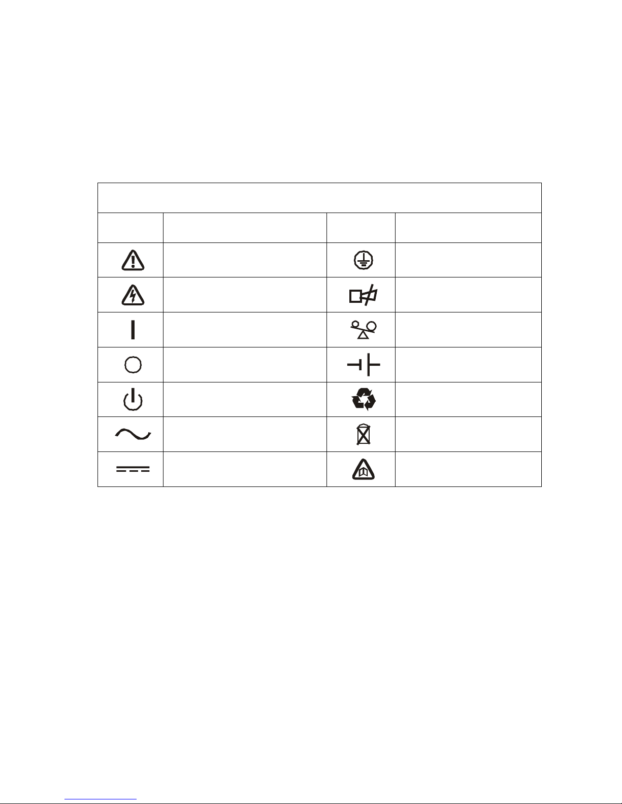
2. DESCRIPTION OF COMMONLY USED NOTATIONS
Some or all of the following Notations may be used in this manual and may appear in
your application process. Therefore, all users should be familiar with them and
understand their explanations.
Notation and Explanation
Notation Explanation Notation Explanation
Alert you to pay special attention
Protective ground
Caution of high voltage
Alarm silence
Turn on the UPS
Overload indication
Turn off the UPS
Battery
Idle or shut down the UPS
Recycle
Alternating current source (AC)
Do not dispose with ordinary
trash
Direct current source
Refer to manual
Page 9

-5-
3. INTRODUCTION –EP700/1000/2000/3000/6000
This On-Line-Series is an uninterruptible power supply incorporating double-converter
technology. It provides perfect protection specifically for Novell, Windows NT and
UNIX servers.
The double-converter principle eliminates all mains power disturbances. A rectifier
converts the alternating current from the socket outlet to direct current. This direct
current charges the batteries and powers the inverter. On the basis of this DC voltage,
the inverter generates a sinusoidal AC voltage, which permanently supplies the loads.
Load like computers and periphery are thus powered entirely by the mains voltage. In
the event of power failure, the maintenance-free batteries power the inverter.
This manual covers the UPS listed as follows. Please confirm whether it is the model
you intend to purchase by performing a visual inspection of the Model No. on the rear
panel of the UPS.
Model No. Type
EP 700T
EP 1000T
EP 2000T
EP 3000T
EP 6000T
Tower Model
EP 700LRT
EP 1000LRT
EP 2000LRT
EP 3000LRT
EP 6000LRT
Tower Model with Long backup time
EP 700R
EP 1000R
EP 2000R
EP 3000R
EP 6000R
Rack Model
Page 10
-6-
4. SYSTEM DESCRIPTION – EP700/1000/2000/3000/6000
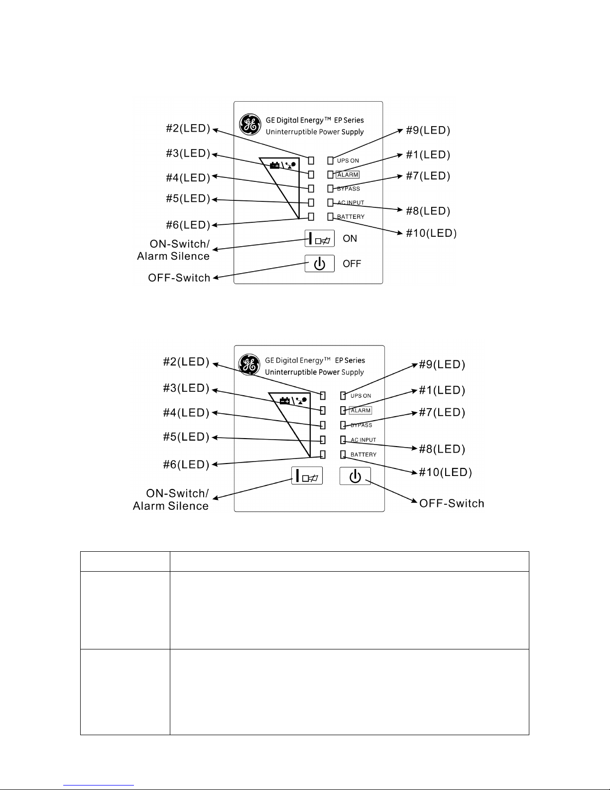
Switch Function
ON - Switch
Turn on UPS system:
By pressing the ON-Switch ON the UPS system is turned on.
Deactivate acoustic alarm:
By pressing this switch an acoustic alarm can be deactivated.
OFF-Switch
When mains power is normal and Bypass is enable, the UPS system switches to
Standby mode by pressing OFF-Switch OFF. It is then switched to Bypass and
the inverter is off. At this moment, maybe the output sockets are supplied with
voltage via the bypass if the mains power is available and bypass is enable.
When UPS is on battery mode, pressing OFF-Switch OFF will shutdown UPS.
EP700T/700LRT/1000T/1000LRT/2000T/2000LRT
/3000T/3000LRT/6000T/6000LRT
EP700R/1000R/2000R/3000R/6000R
Page 11

-7-
Display Function
AC INPUT LED
The green AC INPUT LED lights up if mains voltage is applied to the UPS input.
AC INPUT LED blinks when the phase and neutral conductor have been
reversed at the input of the UPS system.
If AC INPUT LED and BATTERY LED light up, the mains power supply is out of
tolerance.
BATTERY LED
The orange-coloured BATTERY-LED lights up when the mains power has failed
and the inverter is being powered by the batteries.
BYPASS LED
The orange-coloured BYPASS LED lights up when the UPS system is supplying
voltage provided by the mains power via the bypass.
UPS ON LED
The green-coloured UPS ON LED lights up if the UPS system is supplying
voltage provided by the mains power via the inverter.
ALARM LED
The red ALARM LED lights up and an acoustic warning signal is issued
continuously when the UPS system is in fault condition. Press the OFF switch in
order to turn off the warning tone.
Display Function
LOAD and
BATTERY
CAPACITY
LEDs(#2~#6)
(For
EP700/1000/2000
/3000)
These LEDs show the load of the UPS system if the mains power is available
(normal operation):
2nd LED: 96%-108% 3rd LED: 71%-95% 4th LED: 51%-70%
5th LED: 31%-50% 6th LED: 0-30%
In the battery operation, the LEDs indicate the capacity of the batteries:
2nd LED: 100% 3rd LED: 76%-100% 4th LED: 51%-75%
5th LED: 26%-50% 6th LED: 0-25%
LOAD and
BATTERY
CAPACITY
LEDs(#2~#6)
(For EP6000)
These LEDs show the load of the UPS system if the mains power is available
(normal operation):
2nd LED: 96%-105% 3rd LED: 76%-95% 4th LED: 56%-75%
5th LED: 36%-55% 6th LED: 0-35%
In the battery operation, the LEDs indicate the capacity of the batteries:
2nd LED: 81%-100% 3rd LED: 61%-80% 4th LED: 41%-60%
5th LED: 21%-40% 6th LED: 0-20%
Page 12

-8-
5. CONNECTION AND OPERATION – EP700/1000/2000/3000
5.1 Inspection: Inspect the packaging carton and its contents for damage. Please inform
the transport agency immediately should you find signs of damage.
Please keep the packaging in a safe place for future use.
Note: Please ensure that the incoming feeder is isolated and secured to prevent it from
being switched back on again.
5.2 Connection:
1) UPS Input Connection
If the UPS is connected via the power cord, please use a proper socket with
protection against electric current, and pay attention to the capacity of the socket:
over 7A for EP 700/1000, over 12A for EP 2000 and over 16A for EP 3000.
2) UPS Output Connection
The output of EP 700/1000/2000/3000 are socket-types only. Simply plug the load
power cord to the output sockets to complete connection.
Model No. Output Socket (pcs)
EP 700 4
EP 1000 4
EP 2000 6 for Tower & 4 for Rack
EP 3000 6 for Tower & 2 for Rack
3) Computer Connection:
Connect your load to the outlet sockets of the UPS system directly.
5.3 Battery Charge: Fully charge the batteries of the UPS system by leaving the UPS
system connected to the mains for 1-2 hours. You may use the UPS system directly
The system may be installed and wired only by qualified electricians in
accordance with applicable safety regulations!
When installing the electrical wiring, please note the rated current
of your
incoming feeder
Caution!
Do not connect equipment which would overload the UPS system (e.g. laser
printers)
Page 13

-9-
without charging it but the stored energy time may be shorter than the nominal value
specified.
5.4 Turn On the UPS:
1) With utility power connecting:
Press ON button continuously for more than 1 second to turn on the UPS. Then the
UPS will get into self-test status first. After having finishing the self-test, the UPS will
get into the inverter mode, at this time, the AC INPUT LED, Inverter LED, and Load
and Battery Capacity LEDs will light up.
2) Without utility power connecting:
Even though utility power is not connected to the UPS, the UPS still can be turned
on by just simply pressing ON button continuously for more than 1 second. Then
the UPS will get into self-test status first. After having finishing the self-test, the UPS
will get into the inverter mode, at this time, Battery LED, Inverter LED, Load and
Battery Capacity LEDs will light up.
Note: The default setting for bypass mode is no output after UPS is connecting utility
power and breaker is turned on. This can be configured by monitoring software.
5.5 Test Function:
Test the function of the UPS system by either pressing the On button or disconnecting
the input of the UPS system from the power supply.
5.6 Turn Off the UPS:
1) In Inverter Mode:
Press OFF button continuously for more than 1 second to turn off the UPS. Then the
UPS will get into LED self-test status first. After having finished the self-test, the UPS
will get into Standby mode (or Bypass mode if Bypass enable) and the AC INPUT
LED (and Bypass LED if Bypass enable) will light up. At this time, the UPS might has
output (if Bypass enable). Disconnect the utility power to turn off the output.
2) In Battery Mode:
Press OFF button continuously for more than 1 second to turn off the UPS. Then the
UPS will get into self-test status first. After having finished the self-test, the UPS will
be turned off completely.
5.7 Audible Alarm Mute Function: If the alarm is too annoying in battery mode, you
may press ON button continuously for more than 1 second to clear it. Moreover, the
alarm will be enabled when the battery is low to remind you to shutdown the load
soon.
Page 14

-10-
5.8 Operation Procedure of External Battery
1) Use the battery pack with voltage: 36VDC for EP 700/1000 (3 pcs of 12V batteries),
96VDC for EP 2000/3000 (8 pcs of 12V batteries). Connection of batteries more than
or less than required will cause abnormality
2) One end of the external battery cord is a plug for connecting the UPS and the other
end has a plug for connecting the user battery cabinet
3) (Do not connect the UPS to any load at this time). Then, connect the power cord of
the UPS to supply utility power to the UPS to make the UPS operate in utility power
mode.
4) Connect the plug of the external battery cord to the external battery socket on the
rear panel of the UPS to complete the connection procedure and the UPS will start to
charge the battery pack.
Caution!
The output sockets of the UPS system may still be electrically live even if the power
supply system has been disconnected.
Page 15

-11-
6. TROUBLE SHOOTING - EP700/1000/2000/3000
If the UPS system does not operate correctly, please attempt to solve the problem using
the table below.
Problem Possible cause Remedy
No indication, no warning tone even
though system is connected to
mains power supply
No input voltage
Check building wiring socket
outlet and input cable.
AC INPUT LED blinks
Phase and neutral
conductor at input of
UPS system are
reversed
Rotate mains power socket by
180° or connect UPS system.
AC INPUT LED blinks and
BATTERY-LED lights up
Input power and/or
frequency are out of
tolerance
Check input power source and
inform seller if necessary
AC INPUT and BYPASS LED light
up even though the power supply is
available
Inverter not switched on
Press On-Switch ON
UPS ON LED lights up, and audible
alarm sounding every 1 beep in
every 4 seconds
Mains power supply has
failed
Switching to battery mode
automatically. When audible
alarm sounding every second,
battery capacity is low.
ALARM LED lights, warning tone
once a second
Overload Remove loads from UPS output.
ALARM LED lights up, permanent
warning tone
UPS fault Notify seller!
Emergency supply period shorter
than nominal value
Batteries not fully
charged / batteries
defect
Charge the batteries for at least
3 hours and then check capacity.
If the problem still persists,
consult seller.
ALARM LED lights, BATTERY-LED
blinks, warning tone once a second
Charger or Batteries
damaged
Notify seller !
Please have the following information at hand before calling the After-Sales Service Department:
● Model number, serial number
● Date on which the problem occurred
● Detailed description of the problem
Page 16

-12-
7. MAINTENANCE - EP700/1000/2000/3000
7.1 Operation
The UPS system contains no user-serviceable parts. If the battery service life (3 - 5
years at 25°C ambient temperature) has been exceeded, the batteries must be
replaced. In this case please contact seller.
7.2 Storage
If the batteries are stored in temperate 20°C~25°C, they should be charged every three
months for 1-2 hours. You should shorten the charging intervals to two months at
locations subject to high temperatures.
Page 17

-13-
8.TECHNICAL DATA - EP700/1000/2000/3000
8.1 Electrical specifications
INPUT
Model No. EP700 EP1000 EP2000 EP3000
Phase Single
Frequency (46~54)Hz for 50Hz system & (56~64)Hz for 60Hz system
Current(A) 7A 7A 12A 16A
OUTPUT
Model No. EP700 EP1000 EP2000 EP3000
Power rating(VA/W)
700/490 1000/700 2000/1400 3000/2100
Voltage
220/230/240VAC 士 2%
Frequency
50/60Hz ±0.2% (Battery mode)
Wave form Sine Wave
BATTERIES
Model No. EP700 EP1000 EP2000 EP3000
Number and type
3×12V 7.2Ah 3×12V 7.2Ah 8×12V 7.2Ah 8×12V 7.2Ah
8.2 Operating Environment
Operating Temperature
0 oC to 40 oC(20°C~25°C recommended)
Operating humidity < 95%
Altitude < 1000m
Storage temperature -15 oC ~ 40 oC
Note: if 1000m < Altitude < 3500m (output derating: 1% derating per 100m )
8.3 Typical stored energy time (Typical values at 25°C in minutes:)
Model No. 100 % Load 50 % Load
EP700 5 10
EP1000 5 10
EP2000 5 10
EP3000 5 10
Page 18

-14-
8.4 Dimensions and weights
Model No.
Dimensions W x D x H
(mm)
Net Weight
(kg)
EP700T 145X400X220 14
EP700LRT 145X400X220 7
EP700R 482X420X87 15
EP1000T 145X400X220 14
EP1000LRT 145X400X220 7
EP1000R 482X420X87 15
EP2000T 192 X460X340 34.5
EP2000LRT 192 X460X340 15
EP2000R 482X420X87 9.6
EP3000T 192 X460X340 35.5
EP3000LRT 192 X460X340 16
EP3000R 482X420X87 10
Battery pack 96V Rack 482X420X87 26
Page 19
-15-
9. TECHNICAL DATA – EP6000
9.1 General Specification
Model EP6000 EP6000LRT EP6000R
Battery pack
(240V)
Power Rating
(VA/W)
6000/4200
Frequency (Hz) 50/60
Voltage (176-276)VAC
Input
Current 31A max.
Voltage 240VDC
Battery
Current 24A max
Voltage 220/230/240VAC
Output
Current 27A
Dimension (WxDxH)
mm
260x570x717 260x570x717
482.6X600X130
(3U)
482.6X600X130
(3U)
Net Weight (kg) 90 35 18.3 64.2
9.2 Electrical Performance
Input
Model Voltage Frequency Power Factor
EP6000 Single-phase
(46~54)Hz for 50Hz system
(56~64)Hz for 60Hz system
>0.98 (Full load)
Output
Voltage
Regulation
Power
Factor
Frequency
tolerance.
Distortion Overload capacity
Current
crest ratio
±2%
0.7 lag
Synchronized
46-54Hz in Line
mode (AC mode)
±0.1% of normal
frequency in
Battery mode
THD<3% Full
load (Linear
Load)
105%-
130% load transfers
to bypass mode after 10
seconds
>130% load transfers to
bypass mode after 1
second and shutdown the
output after 1 minute
3:1
maximum
Page 20

-16-
9.3 Operating Environment
Temperature Humidity Altitude Storage temperature
0°C~40°C
<95% <1000m
-15°C~40°C
Note: Output power is derated when UPS is above 1000m as following:
Altitude (M) 1000 1500 2000 2500 3000 3500 4000 4500 5000
Derating Power 100% 95% 91% 86% 82% 78% 74% 70% 67%
Page 21

-17-
10. INSTALLATION - EP6000
10.1 Unpacking and Inspection
1) Unpack the packaging and check the package contents. The shipping package
contains:
l An UPS
l An user manual
l A communication cable (RS232)
l A communication cable (USB)
l A Software CD
l SNMP card (optional)
l Battery cable (long backup time model battery pack only)
2) Inspect the appearance of the UPS to see if there is any damage during
transportation. Do not turn on the unit and notify the carrier and seller
immediately if there is any damage or lacking of some parts.
10.2 Input and output power cords and protective earth ground installation
1. Notes for installation
1) The UPS must be installed in a location with good ventilation, far away from
water, inflammable gas and corrosive agents.
2) Ensure the air vents on the front and rear of the UPS are not blocked. Allow at
least 0.5m of space on each side.
3) Condensation may occur if the UPS is unpacked in a very low temperature
environment. In this case it is necessary to wait until the UPS is fully dried
inside before proceeding installation and use. Otherwise there are hazards of
electric shock.
2. Installation
Installation and wiring must be performed in accordance with the local electric
code and the following instructions by professional person.
For safety, please cut off the mains power switch before installation.The battery
breaker also needs to be cut off if it is a long backup time model (“LRT” model)
or Rack model (“R” model).
1) Open the terminal block cover located on the rear panel of the UPS, please
refer to the appearance diagram.
2) It is recommended to select the UL1015 10AWG(6mm2) wire or other
insulated wire which complies with AWG Standard for the UPS input and
Page 22
-18-
output wirings.
Note: Do not use the wall receptacle as the input power source for the UPS, as its
rated current is less than the UPS’s maximum input current. Otherwise the
receptacle may be burned and destroyed.
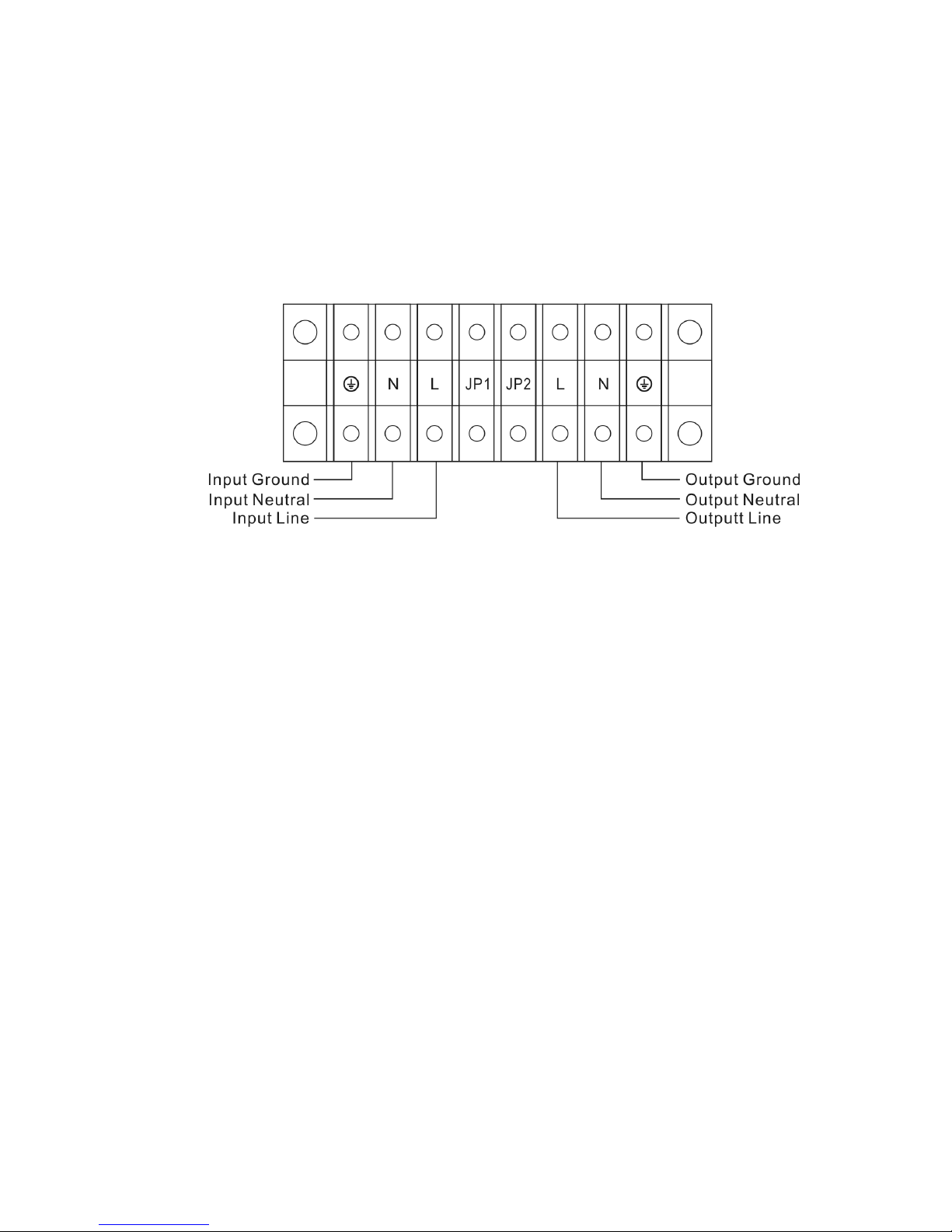
3) Connect the input and output wires to the corresponding input and output
terminals according to the following diagram.
Note: you must make sure that the input and output wires and the input and
output terminals are connected tightly.
4) It is recommended to select the UL1015 10AWG(6mm2) green wire with
yellow ribbon for protective earth ground wire.
5) After having completed the installation, make sure the wiring is correct.
6) Please install the leak current protective breaker at the output power
distribution panel of the UPS if necessary.
7) To connect the load with the UPS, please turn off all the loads first, then
perform the connection and finally turn on the loads one by one.
8) No matter the UPS is connected to the utility power or not, the output of the
UPS may have electricity. The parts inside the unit may still have hazardous
voltage after turning off the UPS. To make the UPS have no output, power off
the UPS, and then disconnect the utility power supply.
9) Suggest charging the batteries for 8 hours before use. After connection, turn
the input breaker in the “ON” position, the UPS will charge the batteries
automatically. You can also use the UPS immediately without charging the
batteries first, but the backup time may be less than the standard value.
10) If it is necessary to connect the inductance load such as a monitor or a laser
printer to the UPS, the start-up power should be used for calculating the capacity
of the UPS, as its start-up power consumption is too big when it is started.
Input and output Terminal Block wiring diagram of EP6000
Page 23

-19-
10.3 Operating procedure for connecting the long backup time model
UPS with the external battery
1) The nominal DC voltage of external battery pack is 240VDC. Each battery pack
consists of 20 pieces of 12V maintenance free batteries in series. To achieve
longer backup time, it is possible to connect multi-battery packs, but the
principle of “same voltage, same type” should be strictly followed.
2) The connector of the external battery cable is used to plug into the external
battery socket of the UPS, the other end of the external battery cable is used to
connect with the external battery pack(s). The procedure of installing battery
pack should be complied with strictly. Otherwise you may encounter the
hazardous of electric shock.
a) Set the battery pack breaker in “OFF” position.
b) You must connect the external battery cable to the battery first, if you
connect the cable to the UPS first, you may encounter the hazardous of
electric shock. Then connect the other end to UPS.
3) To complete the connection by plugging the connector of the external battery
cable into the external battery socket of the UPS. Do not attempt to connect
any loads to the UPS now. You should connect the input power wire to the
right position first. And then set the breaker of the battery pack in the ON
position. After that set the input breaker in the ON position. The UPS begins
to charge the battery packs at the time.
Page 24

-20-
11. OPERATION AND OPERATING MODE – EP6000
It is easy to operate the equipment. Please read through this manual and operate
according to the instructions in it.
Please refer to the appendix 2 for the meaning of the LED indicators.
11.1 Turn on the UPS with utility power supplied (in Line mode/AC mode)
1).After you make sure that the power supply connection is correct, set the bypass
breaker in the “UPS” position and input breaker in the “ON” position first. At this
time the fan rotates, and the UPS operates in Bypass mode or in Standby mode.
2) To power on the UPS by simply pressing the “ON” button continuously for more
than 1 second.
3) When being powered on, the UPS will perform self-diagnosis, with the
load/battery level LEDs turned on and then off one after another in ascending
order. A few seconds later, the UPS ON LED is turned on, the UPS is already
running in Utility Power mode. If the utility power is abnormal, the UPS will
operate in battery mode without output interruption of the UPS.
11.2. Turn on the UPS with no utility power supplied (in Battery mode)
1).For long back up time model (“LRT” model), please make sure that the battery
breaker is in “ON” position.
2) Press the “ON” button continuously for more than 1 second to power on the UPS.
3) During the course of starting up, the UPS has the same action as if it is connected
to utility power except that the utility power LED is not turned on and the battery
LED is turned on instead.
11.3 Turn off the UPS with utility power supplied (in Line mode/AC mode)
1) Press the “OFF” button continuously for more than 1 second to turn off the
inverter of the UPS immediately.
2) When being powered off, the UPS will perform self-diagnosis, the Load/Battery
level LEDs will be turned on and then off one after another in ascending order,
then the UPS ON LED will be turned off. The UPS will be working in Standby
mode. But if Bypass is enable, bypass LED will be turned on and the UPS will be
working in Bypass mode.
3) Upon completion of the above to turn UPS off, output of electric current of the
UPS may be still present (Bypass mode). In order to cut off the output from the
UPS, simply cut off the utility power supply and the UPS will perform
self-diagnosis, finally no any display is shown on the display panel and no voltage
Page 25
-21-
output is available from the UPS output.
11.4 Turn off the UPS with no utility power supplied (in Battery mode)
1) Press the “OFF” button continuously for more than 1 second to power off the
UPS.
2) When being powered off, the UPS will perform self-diagnosis, the Load/Battery
level LEDs will be turned on and then off one after another in ascending order.
Finally no any display is shown on the display panel and no voltage is available
from the UPS output.
Suggestions: Please turn off the connected loads before turning on the UPS and
turn on the loads one by one after the UPS is working in INV mode.
Turn off all of the connected loads before turning off the UPS.
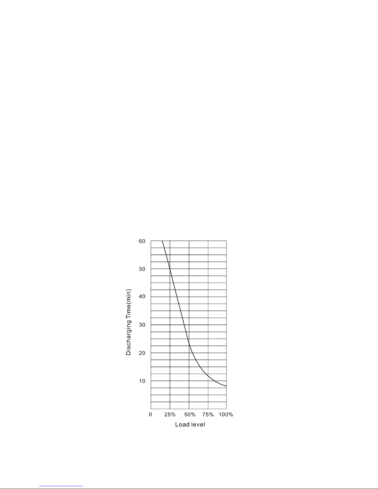
11.5. Backup time for the standard model
The backup time of the long backup time model is dependent on the external
battery pack capacity and the load level as well as other factors.
The backup time of standard model may vary from different load level. Please refer
to the following:
Backup time of EP6000
Page 26

-22-
12. TROUBLE SHOOTING - EP6000
Problem Possible cause Solution
The #1 ALARM LED and the #6
LED are turned on, the buzzer
beeps continuously.
The UPS transfers to fault
mode due to internal
overheat.
Make sure the UPS is not overloaded; the air vents
are not blocked and the ambient temperature is not
too high. Wait for 10 minutes for the UPS to cool down
before turning on again. If failed, please contact the
distributor or service center.
The #1 ALARM LED and the #2 and
#5 LED are turned on, and the
buzzer beeps continuously.
The UPS output is short
circuited.
Remove all the loads. Turn off the UPS. Ensure that
the load is not failed or the UPS has no internal faults
before turning it on again. If failed, please contact the
distributor or service center.
The #1 ALARM LED and the #4
LED are turned on, the UPS beeps
continuously.
The UPS transfers to fault
mode due to its internal
fault.
Please contact the distributor or service center.
The #1 ALARM LED and the #5
LED are turned on, the UPS beeps
continuously.
The UPS transfers to fault
mode due to its internal
fault.
Please contact the distributor or service center.
The AC INPUT LED flashes.
The voltage or frequency
of the utility power is out of
the input range of the
UPS.
The UPS is running in battery mode. To save your
data and close the application program. Make sure
the utility power is within the input voltage or
frequency range permitted by the UPS.
The #1 ALARM LED and the #2
LED are turned on, the UPS beeps
continuously.
The UPS is overloaded or
the load equipment is
faulty.
Check the loads and remove all no-critical equipment.
Recalculate the load power and reduce the number of
loads connected to the UPS. Check that the loads are
not failed.
The #1 ALARM LED is turned on,
and the BATTERY LED is flashed,
the buzzer beeps every second.
The charger of the UPS is
defective.
Please contact the distributor or service center.
BATTERY LED flashes
Battery low or battery not
connected.
Check the battery. If the battery is damaged, please
contact the distributor or service center.
The utility power is normal, but the
UPS can not turn in line mode
Maintain switch loose Please contact the distributor or service center.
Battery not yet been fully
charged.
Keep UPS connected to utility power persistently for
more than 10 hours to recharge the batteries again.
UPS overloaded.
Check the loads and remove the non-critical
equipment.
Battery discharging time diminishes
Battery aged.
Replace the batteries. Please contact the distributor
to obtain the parts and replacement service.
The “ON” button is
pressed too briefly.
Press the “ON” button for more than 1 second.
The UPS is not connected
to the battery or the
battery pack voltage is too
low.
Check the battery or recharge the battery.
The UPS cannot power on after
pressing the ON button
UPS fault. Please contact the distributor or service center.
When you contact the service center, please provide the following information:
● Model No. and the serial No. of the UPS
● The date when the problem arose
● Complete description of the problem, including the LED display, alarm warning, and power
condition and load capacity. If your UPS is a long backup time model, you may also provide the
battery information.
Page 27

-23-
13.NOTES FOR BATTERY DISPOSAL AND BATTERY
REPLACEMENT
1) Before disposing of batteries, remove conductive object such as necklace, wrist
watches and rings.
2) If it is necessary to replace any connection cables, please purchase the original
materials from the authorized distributors or service centers, so as to avoid
overheat or spark resulting in fire due to insufficient capacity.
3) Do not dispose of batteries or battery packs in a fire, they may explode.
4) Do not open or mutilate batteries, released electrolyte is highly poisonous and
harmful to the skin and eyes.
5) Do not short the positive and negative of the battery electrode, otherwise, it may
result in electric shock or fire.
6) Make sure that there is no voltage before touching the batteries. If the battery
circuit is not isolated from the input potential circuit, there may be hazardous
voltage between the battery terminals and the ground.
7) Even though the input breaker is disconnected, the components inside the UPS are
still connected with the batteries, and there are potential hazardous voltages.
Therefore, before any maintenance and repairs work is carried out, switch off the
breaker of the battery pack or disconnect the jumper wire of connection between
the batteries.
8) Batteries contain hazardous voltage and current. Battery maintenance such as the
battery replacement must be carried out by qualified personnel. No other persons
should handle the batteries.
Page 28

-24-
14. BATTERY MAINTENANCE
l This series UPS doesn’t requires much maintenance. The battery used for
standard models are value regulated sealed lead-acid maintenance free battery.
The only requirement is to charge the UPS regularly so as to maximize the
expected life of the battery. When being connected to the utility power, whether the
UPS is turned on or not, the UPS keeps charging the batteries and also offers the
protective function of overcharging and over-discharging.
l The UPS should be charged once every 4 to 6 months if it has not been used for a
long time.
l In hot regions, the battery should be charged and discharged every 2 months. The
standard charging time should be at least 12 hours.
l Under normal conditions, the battery life lasts 3 to 5 years. In case if the battery is
found not in good condition, earlier replacement should be made. Battery
replacement should be performed by qualified personnel.
l Replace batteries with the same number and same type of batteries.
l Do not replace the battery individually. All the batteries should be replaced at the
same time following the instructions of the battery supplier.
l Normally, the batteries should be charged and discharged once every 4 to 6
months. Charging should begin after the UPS shuts down automatically in the
course of discharging, the standard charging time for the standard UPS should be
at least 12 hours.
Page 29

-25-
15. OPERATING MODE FOR ALL MODELS
15.1 Utility power mode
The display panel in utility power mode is
shown in the following diagram. The AC input
LED and the UPS ON LED are turned on.
The load level LEDs will be turned on in
accordance with the load capacity
connected.
1) The battery LED is turned on and the AC
INPUT LED flashes, it indicates the
voltage or frequency of the utility power
has exceeded the normal range, the UPS
operates in battery mode.
2) If output overloaded, the load level LEDs
will be turned on and alarm will keep twice
every second. You should get rid of some
unnecessary loads one by one to decrease the loads connected to the UPS less
than 90% of its nominal power capacity.
Note: Please follow the following steps to connect the generator:
l Activate the generator and wait until the operation is stable before supplying
power of the generator to the UPS (be sure that the UPS is in idle mode, no
load). Then turn on the UPS according to the start-up procedure. After the
UPS is turned on, then the loads can be connected to the UPS one by one.
l The power capacity of the AC generator should be at least twice of the UPS
capacity.
15.2 Battery mode
The display panel in battery mode is shown in the following diagram Fig.15.2. The
battery LED and the UPS ON LED are turned on. The displayed number of the
battery level LEDs will be turned on in accordance with the battery capacity. Note
that the load level LEDs in utility power mode will indicate the level of the battery
capacity in battery mode instead.
1) When the UPS is running in battery mode, the buzzer beeps once every 4
seconds. If the “ON” button on the front panel is pressed for more than 1 second
again, the buzzer will stop beeping (in silence mode). Press the “ON” button once
The utility power mode
Page 30
-26-
again for more than 1 second to resume
the alarm function.
2) When the battery capacity decreases,
the number of the battery capacity LEDs
turned on will be reduced. If the battery
voltage descends to the alarm level, the
buzzer will beep once every second to
remind the users of insufficient battery
capacity and the UPS is soon going to
shut down automatically. Then the load
operations should be carried out
promptly and the loads should be
eliminated one by one.
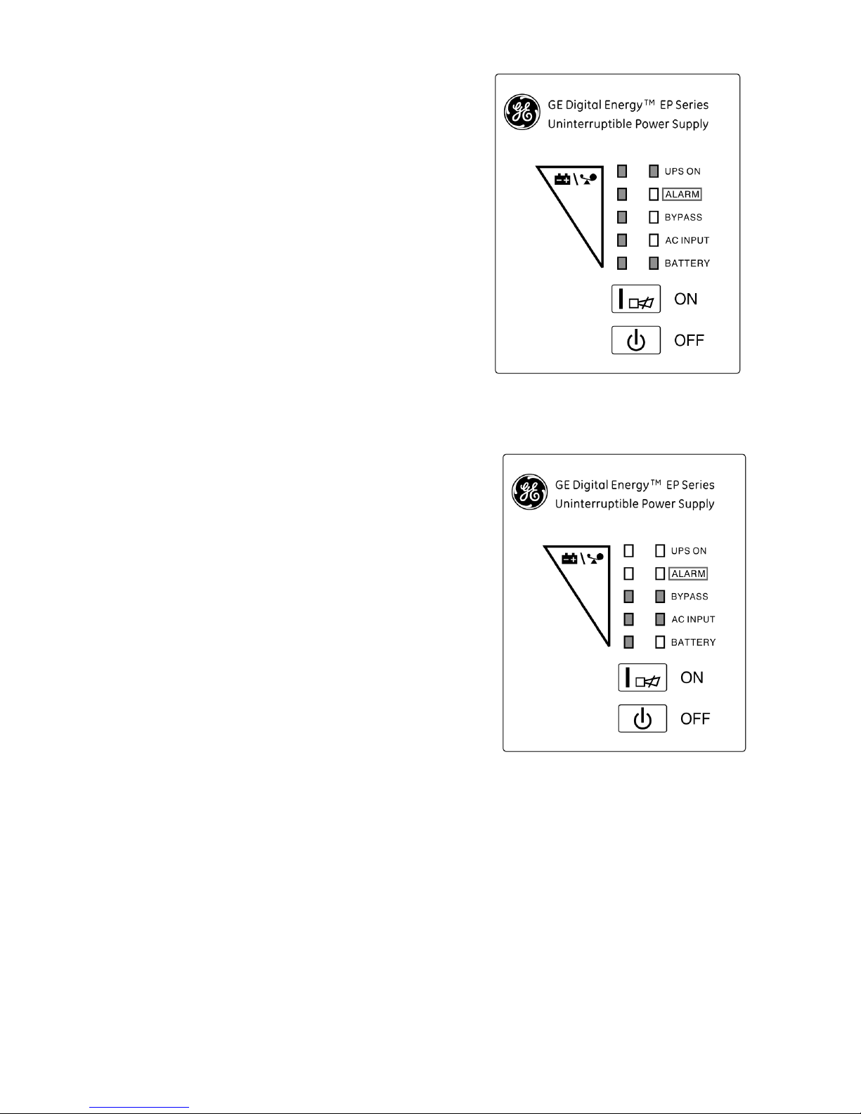
15.3 Bypass mode
The display panel in bypass mode is shown
in the following diagram Fig 15.3. The AC
INPUT LED and the bypass LED are turned
on. The displayed number of the load LEDs
will be turned on in accordance with the load
capacity connected. The UPS will beep once
every 2 minutes in bypass mode.
The AC INPUT LED flashes, it shows that the
voltage or frequency of the utility power has
exceeded the normal range of the UPS.
1)Other indications on the display panel are
the same in utility mode.
2)The UPS does not have the backup
function when it is in bypass mode. The
power used by the load is supplied from the utility power via internal filter.
15.4 Abnormality mode
In case the fault LED is turned on when the UPS is in use, it shows that the UPS is
operating in abnormal mode.
Battery mode diagram
UPS bypass mode diagram
Page 31

-27-
16. COMMUNICATION PORT
16.1 RS232 Interface
The following is the pin assignment and description of DB-9 connector.
16.2 USB Interface
Except for the communication protocol as mentioned above, this series UPS has
USB card for USB1.1 communication protocol.
16.3 SNMP communication (Option)
Except for the communication protocol as mentioned above, this series UPS has
SNMP communication card (an optional accessory) for SNMP communication
protocol. Please contact your local distributor for details. The following is the card
panel description.
Pin # Description I/O
2 TXD Output
3 RXD Input
5 GND Input
Page 32

-28-
17. SOFTWARE FOR ALL MODELS
EP Series OS Shutdown Software
EP Series OS Shutdown Software is a multifunctional UPS monitoring software, which
provides user-friendly interface to monitor and control your UPS. This unique software
provides safely auto shutdown for multi-computer systems while power failure. With
this software, users can monitor and control any UPS on the same LAN or even
Internet no matter how far it is.
Please refer to enclosed software user manual for installation and using.
Page 33

-29-
Appendix 1: Corresponding Form of the LED Display
- EP700/1000/2000/3000
LED display
No.
Operating state
#
1
#
2
#
3
#
4
#
5
#
6
#
7
#
8
#
9
#
10
Alarm warning
1
0~30%
Load capacity
● ●
●
none
2
31%~50%
Load capacity
●
●
●
●
none
3
51%~70%
Load capacity
●
● ●
●
●
none
4
71%~95%
Load capacity
●
● ● ●
●
●
none
5
Utility
Power
Mode
96%~108%
Load capacity
●
● ● ● ●
●
●
none
6
0~25%
Battery capacity
● ● ● Beep once every sec
7
26%~50%
Battery capacity
●
●
● ● Beep once every 4 sec
8
51%~75%
Battery capacity
●
● ●
● ● Beep once every 4 sec
9
76%~100%
Battery capacity
●
● ● ●
● ● Beep once every 4 sec
10
Battery
Mode
100%
Battery capacity
●
● ● ● ●
● ● Beep once every 4 sec
11
Bypass mode ↑
↑ ↑ ↑
● ● ●
Beep once every 2 min.
12
overloaded in utility mode and
UPS still in INV mode
●
● ● ● ●
●
●
Beep twice every sec.
13
overloaded in utility mode and
UPS in bypass mode
● ● ● ● ● ● ● ●
Continuously beep
14
Utility power abnormal
↑
↑ ↑ ↑ ● ↑ ★ ↑ ↑
↑
15
Overloaded in battery mode,
Early-warning
↑
↑ ↑ ↑ ↑
↑
●
● Beep twice every sec.
16
Overloaded in battery mode,
Cut off the output
● ●
Continuously beep
17 Over temperature ●
●
↑ ↑
Continuously beep
18 Inv abnormal ●
● ↑
↑
Continuously beep
19 Output short circuited ●
●
● ↑ Continuously beep
20 BUS voltage abnormal ●
● ↑
↑
Continuously beep
21 Charger voltage too high ●
● ↑
↑
Continuously beep
22 Fan abnormal ●
●
●
↑ ↑ ↑
Beep once every sec
23 Charge or battery failed ●
★
Beep once every sec
24 Battery voltage abnormal ↑
↑ ↑ ↑ ↑ ●
★
↑
25
Site Fault ↑
↑ ↑ ↑ ● ↑ ★ ↑ ↑
Beep once every 2 min.
●: Solid ON ★: Flash ↑:LED display and alarm warning are dependent on other conditions.
Page 34

-30-
Appendix 2: Corresponding Form of the LED Display
- EP6000
LED display
No
Operating state
#
1
#
2
#
3
#
4
#
5
#
6
#
7
#
8
#
9
# 10
Alarm warning
1
0~35%
Load capacity
● ●
●
none
2
36%~55%
Load capacity
●
●
●
●
none
3
56%~75%
Load capacity
●
● ●
●
●
none
4
76%~95%
Load capacity
●
● ● ●
●
●
none
5
Utility
Power
Mode
96%~105%
Load capacity
●
● ● ● ●
●
●
none
6
0~20%
Battery capacity
● ●
●
Beep once every sec
7
21%~40%
Battery capacity
●
●
●
●
Beep once every 4 sec
8
41%~60%
Battery capacity
●
● ●
●
●
Beep once every 4 sec
9
61%~80%
Battery capacity
●
● ● ●
●
●
Beep once every 4 sec
10
Battery
Mode
81%~100%
Battery capacity
●
● ● ● ●
●
●
Beep once every 4 sec
11
Bypass mode ↑
↑ ↑ ↑ ● ● ●
Beep once every 2
min.
12
overloaded in utility mode and
UPS still in INV mode
● ● ● ● ● ●
●
●
Beep twice every sec.
13
overloaded in utility mode and
UPS in bypass mode
● ● ● ● ● ● ● ●
Beep twice every sec.
14
Utility power abnormal ↑
↑ ↑ ↑ ● ↑ ★ ↑ ↑
↑
15
Overloaded in battery mode,
Early-warning
●
↑ ↑ ↑ ↑
↑
● ●
Beep twice every sec.
16
Overloaded in battery mode,
Cut off the output
● ●
↑ Continuously beep
17 Over temperature ● ●
↑ ↑
Continuously beep
18 Inv abnormal ● ● ↑
↑
Continuously beep
19 Output short circuited ●
●
● ↑ Continuously beep
20 BUS voltage abnormal ● ● ↑
↑
Continuously beep
21 Charger and battery failed ● ↑
↑ ↑ ★
Beep once every sec
22 BAT SCR failed ● ● ●
↑ ↑
Continuously beep
23 Fan abnormal ●
●
●
↑ ↑ ↑ ↑
Beep once every sec
24 INV RLY failed ● ● ●
↑ ↑
Continuously beep
25 Communication abnormal ● ● ● ↑ ↑ Continuously beep
●: Solid ON ★: Flash ↑:LED display and alarm warning are dependent on other conditions.
Page 35

-31-
Appendix 3: Safety & EMC Standards
The units comply with the following standards:
EP700/1000/2000/3000
* Safety
IEC/EN 62040-1-1
* EMI
Conducted Emission...............................:IEC/EN 62040-2 Category C1
Radiated Emission..................................:IEC/EN 62040-2 Category C1
Harmonic Current...................................:IEC/EN 61000-3-2
Voltage Fluctuation and Flicker...............:IEC/EN 61000-3-3
* EMS
ESD.........................................................:IEC/EN 61000-4-2 Level 4
RS...........................................................:IEC/EN 61000-4-3 Level 3
EFT..........................................................:IEC/EN 61000-4-4 Level 4
SURGE....................................................:IEC/EN 61000-4-5 Level 4
Low Frequency Signals...........................:IEC/EN 61000-2-2
EP6000
* Safety
IEC/EN 62040-1-1
* EMI
Conducted Emission...............................:IEC/EN 62040-2 Category C3
Radiated Emission..................................:IEC/EN 62040-2 Category C3
*EMS
ESD.........................................................:IEC/EN 61000-4-2 Level 4
RS...........................................................:IEC/EN 61000-4-3 Level 3
EFT..........................................................:IEC/EN 61000-4-4 Level 4
SURGE....................................................:IEC/EN 61000-4-5 Level 4
Low Frequency Signals...........................:IEC/EN 61000-2-2
Warning: This is a product for commercial and industrial application in the
second environment-installation restrictions or additional measures may be
needed to prevent disturbances.
Page 36

-32-
Appendix 4: Back Panel for all models
Page 37

-33-
Page 38

-34-
Page 39

-35-
Page 40

-36-
Page 41

-37-
Page 42

Page 43

목 차
1. 안 전 지 침...............................................................................................................................................1
1.1 설치 ...................................................................................................................................................1
1.2 운전 ...................................................................................................................................................2
1.3 정비, 서비스 및 고장 ........................................................................................................................2
1.4 운반 ...................................................................................................................................................3
1.5 보관 ...................................................................................................................................................3
2. 일반적으로 사용된 표기의 설명 ............................................................................................................4
3. EP700/1000/2000/3000/6000 소개.......................................................................................................5
4. 제품 전면 사양 - EP700/1000/2000/3000/6000...................................................................................6
5. 전원 연결 과 조작 -EP700/1000/2000/3000.........................................................................................8
6. 문제해결-EP700/1000/2000/3000......................................................................................................11
7. 유지보수-EP700/1000/2000/3000......................................................................................................12
7.1 운영 .................................................................................................................................................12
7.2 보관 .................................................................................................................................................12
8. 기술자료 -EP700/1000/2000/3000.....................................................................................................13
8.1 전기적 사양.....................................................................................................................................13
8.2 운영 환경.........................................................................................................................................13
8.3 표준 백업시간 ( 통상 25 ℃에서 분으로 표시).............................................................................13
8.4 제품 치수 및 중량 ..........................................................................................................................14
9. 기술 자료- EP6000...............................................................................................................................15
9.1 일반 사양.........................................................................................................................................15
9.2 전기적 성능.....................................................................................................................................15
Page 44

9.3 운영 환경.........................................................................................................................................16
10.설치- EP 6000.....................................................................................................................................17
10.1 포장 해체 및 검사 .........................................................................................................................17
10.2 입력 및 출력 코드,접지 라인 설치...............................................................................................17
10.3 외부 축전지가 있는 장시간 백업 축전지 모델 동작 순서 ..........................................................19
11. 동작 및 모드 –EP6000.......................................................................................................................20
12. 문제 해결 – EP6000...........................................................................................................................22
13. 축전지 설치 및 교체 시 주의 사항.....................................................................................................23
14 축전지 유지보수 ..................................................................................................................................24
15. 동작 모드 (전 모델)............................................................................................................................25
15.1 상용 전원 모드 ..............................................................................................................................25
15.2 축전지 전원 모드 ..........................................................................................................................25
15.3 바이패스 모드...............................................................................................................................26
15.4 비정상 모드...................................................................................................................................26
16. 통신 포트.............................................................................................................................................27
16.1 RS232 인터페이스.......................................................................................................................27
16.2 USB 인터페이스...........................................................................................................................27
16.3 SNMP 통신 카드 (선택 사양).......................................................................................................27
17. 소프트 웨어 ( 모든 모델 )...................................................................................................................28
부록 1: LED 디스플레이에 대한 내용 도표 – EP 700/1000/2000/3000..............................................29
부록 2: LED 표시에 대한 내용 도표 – EP 6000....................................................................................30
부록 3: 안전 및 EMC 표준........................................................................................................................31
부록 4 : 후면 패널 ( 전모델 )....................................................................................................................32
Page 45

- 1 -
1. 안 전 지 침
본 제품을 설치하고 운영하기 전에 본 제품의 사용 설명서와 안전 지침에 관한
내용을 꼭 읽어 주십시오!
1.1 설치
« UPS가 차가운 곳에서 갑자기 따뜻한 곳으로 이동시 응축이(습기) 발생 할 수 있습니다.
UPS는 설치되기 전에 꼭 건조되어야 합니다.
« UPS 를 설치하기 전 적어도 새로운 환경에 적응되도록 2 시간 정도의 시간(습기 제거를
위해)을 두시기 바랍니다.
« 물 가까이 또는 습기가 많은 곳에 설치하지 마십시오.
« 열 가까이 또는 직접적인 햇빛에 노출되는 곳에 설치하지 마십시오
« UPS 가 동작중 원활한 통풍을 위해 환풍구 주위를 막지 마십시오
« UPS 출력 콘센트(OUTLET)에 과부하가 걸릴만한 기구나 장비들을 연결하지
마십시오.(예. 레이저 프린터등)
« 케이블은 포장되어 있는 박스에 있으며 물품을 꼭 확인 하십시오
◇ EP 700/1000/2000/3000 설치
« 출력소켓 및 축전지 연결용 소켓은 접지붙이 입력 코드에 의해 접지되어야 합니다.
UPS 를 켜기전에 출력 코드를 메인 소켓에 연결 시켜 주십시요.
« UPS 는 항상 접지가 되어 있는 벽부 소켓 아울렛에 연결 합니다.
«
건물의 벽부 충격 방지용 소켓 아울렛은 반드시 UPS 근처에 있어서 접근이 가능해야
합니다.
« 상기 모델은 사용자가 설치 사용 가능한 모델입니다.
◇ EP6000 설치
«
EP6000 은 최종 설치 후에 외부 축전지 외함에 연결하는 등전위 접지바와 접지 단자대를
제공합니다.
« 어떠한 동작 모드에서도 부하에 전원 공급을 예방하기 위한 일제형 비상 스위치가 건물
벽부 접지붙이 소켓에 공급 되어야 합니다.
« 단락 후비 보호용으로 적절한 단로기가 건물 분전반에 공급 되어야 합니다.
«
IT (비접지) 접지 계통의 3 상 기기에 연결하기 위해서, 3 상 전원 및 중성선 분리를 위한 4
POLE 단로스위치가 건물 분전반에 설치 되어야 합니다.
Page 46

- 2 -
« UPS 가 영구적으로 기기에 연결 시킬 경우 반드시 자격 있는 작업자가 설치 해야 합니다.
« 건물 분전반에 UPS 를 연결 하기 전에 반드시 접지 라인을 연결 합니다.
1.2 운전
« 동작 중에 UPS 입력 코드나 건물 벽부 접지붙이 소켓에서 코드를 분리하는 경우 UPS 및
UPS 에 연결된 모든 부하의 접지 라인을 분리 될 수 있으므로 입력 코드를 분리 하지
마십시요.
« UPS 에 축전지가 내장되어 있으므로 건물 전원으로 부터 전원이 공급되지 않는다
하더라도, 출력 콘센트나 출력단자쪽에 전류가 흐를 수 있습니다.
« UPS 에서 완전히 전원을 분리 시키려면, 먼저 Standby 버튼을 누른후, 주 부하를 분리
하십시요.
« UPS 에 액체나 그밖에 이물질이 들어가지 않게 확인하십시오.
« UPS 에 사용 경험이 없는 사람도 조작이 가능합니다.
1.3 정비, 서비스 및 고장
«
UPS 가 동작 중일 때 위험한 전압이 발생합니다.수리는 오직 자격 있는 유지 보수
요원만이 하여야 합니다.
« 경고 –감전 위험. UPS가 주 전원(건물 배선 출력 콘센트)으로부터 분리된 후에도 여전히
내부에는 축전지와 연결되어 있고 이로 인해 여전히 잔존 전기가 있으므로 위험합니다.
« 수리 또는 유지 보수 하기 전에 축전지의 연결을 분리하고 현재 어떠한 위험 전압도 BUS-
컨덴서 와 축전지 단자등에 전압이 있는지 확인 하십시오.
« 오직 축전지에 대하여 전문 지식을 가지고 있는 사람만이 축전지를 다루거나 교체시
감독하여야 합니다.
«
허가 받지 않은 사람이 축전지를 다루거나 가까이해서는 안됩니다.
« 경고 –감전 위험. 축전지는 입력으로부터 바로 공급받습니다. 축전지 단자와 접지 사이에
위험 전압이 나타날 수 있습니다. 조작하기 전, 꼭 위험한 전압이 있는지 확인 하십시오.
« 축전지는 감전의 위험이 있으며 높은 단락 전류가 발생 할 수 있습니다. 꼭 아래의 명시된
예방사항의 조치를 취하십시오,축전지를 다루기 전 준비물을 준비하십시오 :
«
손목에 있는 시계와 반지 기타 금속성 물건을 제거 하십시오.
« 오직 절연된 도구와 핸들이 있는 기구를 사용하십시오
« 축전지를 교체 할 때, 설치된 축전지와 동일한 타입과 용량 및 수량으로 설치하십시오.
« 불이나 화기가 있는 곳에 폐기 하지 마십시오 폭발의 위험이 있습니다.
« 축전지를 개방하거나 파손하지 마십시오. 전해물질이 눈이나 피부에 피해를 줄 수
있습니다. 독성이 있을 수 있습니다.
« 꼭 퓨즈를 교체할 경우 화재의 위험을 방지하기 위해서 같은 타입과 용량의 제품으로
교체 하십시오.
Page 47

- 3 -
« UPS 를 임의로 해체하지 마십시오.
1.4 운반
« 운반을 할 때는 꼭 원래의 포장 상태로 이동하십시오(충격과 충돌에 대해서 보호하기
위해).
1.5 보관
« UPS는 통풍이 원활하고 건조한 곳에 보관도어야 합니다..
Page 48

- 4 -
2. 일반적으로 사용된 표기의 설명
아래의 몇개 혹은 모든 표기가 본 매뉴얼에 사용 되어지고 있고 고객의 적용
공정에 나타 날 수 있읍니다. 모든 사용자들은 아래의 표기에 익숙해져야 하며
설명에 대해서 이해해야 합니다.
표기와 설명
표기 설명 표기 설명
특별한 주위를 요구하는
경고표시
보호 접지
경고 고압
알람 경보
UPS 동작
과부하 표시
UPS 정지
축전지 체크
정지 또는 UPS 셧다운
교환
교류전원 (AC)
깨끗한 곳에 UPS 보관
직류전원 (DC)
설명서 참조
Page 49

- 5 -
3. EP700/1000/2000/3000/6000 소개
EP 시리즈 UPS 는 on line double conversion 방식의 무정전 전원 공급 (UPS)
장비입니다.특별히 Novell, Windows NT, 그리고 UNIX 서버를 완벽하게 보호 해 줍니다.
Double conversion 방식으로 모든 입력 전원의 이상을 제거 해 줍니다.정류기는
소켓아울레으로 부터의 교류 전원을 직류 전원으로 바꾸어 줍니다.직류 전원은 축전지를
충전하고 인버터에 전원을 공급 합니다.이 직류전압을 기준으로 인버터는지속적으로
부하에 정현파 교류 전압을 만들어 줍니다.
컴퓨터와 주변기기와 같은 부하는 입력 전원으로 부터 전원을 받습니다. 입력전원이
정전시에 무보수 축전지가 인버터에 전원을 공급합니다.
이 설명서는 아래의 제품에 대한 설명서입니다.제품 후면부에 있는 모델 번호를 확인후
사용하고자 하는 UPS모델을 확인 하십시요.
모델 번호 타입
EP 700T
EP 1000T
EP 2000T
EP 3000T
EP 6000T
타워 모델
EP 700LRT
EP 1000LRT
EP 2000LRT
EP 3000LRT
EP 6000LRT
장시간 백업을 위한 타워 모델
EP 700R
EP 1000R
EP 2000R
EP 3000R
EP 6000R
랙 모델
Page 50

- 6 -
4. 제품 전면 사양 - EP700/1000/2000/3000/6000
EP700T/700LRT/1000T/1000LRT/2000T/2000LRT
/3000T/3000LRT/6000T/6000LRT
EP700R/1000R/2000R/3000R/6000R
스위치 기 능
ON -Switch
UPS 켜기
On-Switch 를 눌러서 UPS 를 켠다.
경보음 소거:
On-Switch 를 누르면 경보음이 소거 된다.
OFF-Switch
입력 전원이 정상이고 바이패스 모드가 동작 가능하면 UPS 는 OFF-
Switch 를 off 하면 대기모드로 전환 된다.바이패스 모드로 전환되면
인버터는 정지한다.이때 입력전원이 들어오고 바이패스 모드가 동작
가능하면 출력 소켓에는 바이패스 라인을 통해서 전원이 공급 되어
진다.UPS가 축전시 모드일때, OFF-Switch 를 off 시키면 UPS 는
완전 정지 한다.
Page 51

- 7 -
표시 기 능
교류 입력 LED
(AC INPUT LED)
입력 전원이 UPS 입력단에 인가 되면 녹색 교류 입력 LED 점등.
UPS 입력단에 상선, 중성선이 잘못 연결 된 경우 AC INPUT LED 가
깜박거림. 만약 AC INPUT LED 와 축전지 LED 가 점등되면, 입력
전원이 입력 범위를 벗어남을 나타냄.
축전지 LED
(BATTERY LED)
입력전원이 정전되면 주황색 축전지 LED 가 점등하고 축전지에서
인버터에 전원을 공급.
바이패스
(BYPASS LED)
UPS 가 바이패스 라인을 통해서 입력 전원이 그대로 공급되는 경우
주황색 바이패스 LED 가 점등.
UPS 동작 LED
(UPS ON LED)
UPS 가 인버터를 통해서 전원을 공급하는 경우 UPS ON LED 가
점등.
경보 LED
(ALARM LED)
UPS 고장시에 경보 LED 가 점등하고 경보음이 지속됨. 경보음을
소거하기 위해서 OFF Switch 를 눌러 준다.
표시 기능
부하 및 축전지
용량 LED(#2~#6)
(EP700/1000/2000
/3000)
입력전원이 정상 공급 중인 경우 LED 를 통해서 부하량을 표시 해
준다:
2nd LED: 96%-108% 3rd LED: 71%-95% 4th LED: 51%-70% 5th
LED: 31%-50% 6th LED: 0-30%
축전시 모드에서는 LED 를 통해서 축전지 잔량을 표시 해 준다.
2nd LED: 100% 3rd LED: 76%-100% 4th LED: 51%-75% 5th LED:
26%-5
0% 6th LED: 0-25%
부하 및 축전지
용량 LED(#2~#6)
(EP6000)
입력전원이 정상 공급 중인 경우 LED 를 통해서 부하량을 표시 해
준다:
2nd LED: 96%-105% 3rd LED: 76%-95% 4th LED: 56%-75% 5th
LED: 36%-55% 6th LED: 0-35%
축전시 모드에서는 LED 를 통해서 축전지 잔량을 표시 해 준다.
2nd LED: 81%-100% 3rd LED: 61%-80% 4th LED: 41%-60% 5th
LED: 21%-40% 6th LED: 0-20%
Page 52

- 8 -
5. 전원 연결 과 조작 -EP700/1000/2000/3000
본 UPS 시스템은 안전 규정에 따라서 자격있는 전기 기술자가 결선 및 설치
해야 합니다.
케이블 결선시에는 UPS 입력단의 정격 전류를 확인 하십시요.
5.1 검사 : UPS 본체에 대한 운반 중 파손 여부에 대한 외관 검사를 실시하십시오. 파손이나
부품의 부족한 경운 즉시 배달원과 판매자에게 알리고 UPS 를 사용 하지
마십시오. 다음 사용시 까지 안전한 장소에 보관하시기 바랍니다.
참조: 입력단이 반드시 분리 되어 있고 다른 작업자에 의해 다시 재 투입되지 않도록 되어
있는지 확인 하십시오.
5.2 연결:
1) UPS 입력 연결
UPS 가 전원 코드에 의해 연결 되는 경우, 전류에 대한 보호기능이 있는 적절한 소켓을
사용 해야 합니다. 그리고 소켓의 정격 용량에 주의 하십시요: EP 700/1000 는 7A이상,
EP 2000 은 12A이상 , EP 3000 은 16A 이상을 사용 해야 합니다.
2) UPS 출력 연결
EP 700/1000/2000/3000 의 출력은 항상 소켓 타입을 사용 합니다.단순히 전원코드의
플러그를 UPS출력 소켓에 연결하면 됩니다.
모델번호
출력
소캣
(개)
EP 70
0 4
EP 1000
4
EP 2000
타워
타입
6 &
랙 타입
4 EP 3000
타워
타입
6 &
랙 타입
4
3) 컴퓨터 연결
UPS 출력 소켓에 바로 컴퓨터를 연결 하십시요.
주의!
UPS 시스템에 용량을 초과할 만한 부하를 연결하지 마시오.(예 : 레이져 프린터)
Page 53

- 9 -
5.3 축전지 충전: UPS 시스템에 주 전원이 연결된 후 축전지가 완전 충전 하기까지에는
1~2 시간이 소요됩니다. 축전지를 완전히 충전하지 않고 사용이 가능합니다. 그러나
백업 시간은 공칭값보다 줄어 듭니다.
5.4 UPS 켜기:
1) 입력 전원이 연결된 상태에서:
1 초간 ON 버턴을 누르면 UPS 가 켜집니다. 먼저 UPS 는 자기 진단 테스트를
수행합니다.자기 진단 테스트 후 UPS 는 인버터 모드로 들어가고 동시에 AC INPUT
LED, 인버터 LED, 배터리 CAPACITY LED 가 점등 합니다.
2) 입력 전원이 연결되지 않은 상태에서:
입력 전원이 UPS에 연결 되지 않는 상태에서도 , ON 버턴을 1 초이상 눌러 주면
UPS 를 켤 수 있읍니다. 그러면 UPS 는 자기진단 테스트를 수행하고 나면 UPS 는
인버터 모드로 들어갑니다. 동시에 축전지 LED, 인버터 LED, 부하 및 축전지
표시 LED 가 점등합니다.
주의: 바이패스 모드의 현재 설정치는 UPS 가 상시 전원에 연결 된 후에는 출력이 없고
차단기는 투입 됩니다. 모니터링 소프트웨어를 통해서 설정이 가능합니다.
5.5 시험 기능:
UPS 는 ON 버튼을 눌러주거나 UPS 입력을 분리하여 테스트가 가능합니다.
5.6 UPS 끄기:
1) 인버터 상태에서:
OFF 버튼을 1초이상 눌러 주면 UPS는 꺼집니다.그러면 UPS는 자기 진단 테스트를
수행하고 UPS는 대기모드( 바이패스모드가 활성화 된경우는 바이패스 모드)로 되고.
AC INPUT LED( 바이패스 모드가 활성화 된경우 바이패스 LED)가 점등합니다. 동시에
UPS 는 출력단을 분리합니다
2) 축전지 상태에서:
OFF 버턴을 1 초 이상 눌러서 UPS 를 껀다. UPS 는 자기 진단 테스트를 수행하고
UPS 는 완전히 꺼진다.
5.7 알람 소거 기능:
축전지 모드에서 경보음이 거슬리는 경우, ON 버튼을 1 초 이상 눌러 주면 경보음이 소거
됩니다. 또한 경보음은 축전지가 저전압으로 떨어지면 부하를 끊어 주게 하기 위해서
다시 경보음이 울립니다.
Page 54

- 10 -
5.8 외부 축전지 조작 순서
1) 축전지팩 사용: EP 700/1000 의 경우 36VDC (12V 축전지 3 개), EP 2000/3000 의
경우 96VDC (12V축전지 8 개). 연결된 축전지가 많거나 적은 경우 UPS 고장을
일으키는 원인이 됩니다.
2) 외부 축전지팩의 마지막 연결 코드는 UPS 에 연결 됩니다. 마지막 코드는 별도 축전지
팩케비넷에 연결 됩니다.
3) (이때 UPS 에 어떤 부하도 연결 하지 마십시요).입력 전원을 UPS에 연결해서 상용
전원모드로 동작 하게 합니다.
4) 외부 축전지팩의 연결 코드를 UPS 후면의 외부 축전지 소켓에 연결하며 UPS 는
축전지를 충전하기 시작 합니다.
주의!
입력 전원이 연결이 안된 경우에도 UPS 출력 소켓에는 여전히 전기적으로 연결 될 수
있읍니다.
Page 55

- 11 -
6. 문제해결-EP700/1000/2000/3000
UPS 가 정상적으로 동작 하지 않을 경우, 아래의 도표를 참조하여 문제를 해결 하십시요.
장 애 가능한 원인 조 치
주 전원을 연결 하였으나
어떠한 표시나 어떠한
경보음도 없음
입력 전압이 없음
건물벽부 출력 소켓의
연결선 및 입력 케이블 확인.
교류 입력(AC INPUT) LED 깜
박임
UPS 입력측 상선과
중성선 연결이 잘못
됨
입력 소켓을 180도 돌려서
연결하거나 UPS에 연결함
AC INPUT LED 깜박임 및
BATTERY-LED 점등
입력 전원 및 주파수
범위 초과
입력 전원 확인 및 필요시
판매자에게 알려줍니다.
전원 공급이 가능한
상태에서도 교류 입력 과
BYPASS LED 점등
인버터 스위치가 ON
되어 있지 않음
On-Switch 를 누르십시오
INVERTER LED 점등 및 4 초
간격으로 1번씩 알람 발생
입력 전원 이상
자동으로 축전지 모드로
전환. 매초마다 지속적으로
경보가 울릴경우,축전지
용량 낮음.
1 번 경고음후 FAULT LED
점등
과부하
UPS 출력의 부하 사용량을
줄이십시오
지속적인 경고음이 울리며
FAULT-LED 점등
UPS 불량 판매자에게 연락
축전시 백업 시간이
공칭값보다 짧은 경우
축전지가 완전
충전되지 않음 /
축전지 결함
적어도 축전지를 3 시간
충전시기코 축전지 용량을
점검합니다. 문제가
지속되면 판매자에게 연락.
ALRAM LED 가
점등하고,BATTERY-LED가
깜박거리고 한번 경고음이
울린다.
충전기 또는 축전지
파손
판매자에게 연락
서비스 센터에 연락할 때, 아래의 내용을 제공하십시요:
• 모델번호, 시리얼번호
• 문제 발생 일자
• 자세한 문제 내용
Page 56

- 12 -
7. 유지보수-EP700/1000/2000/3000
7.1 운영
본 UPS는 사용자가 정비가 가능하지 않습니다. 축전지 사용기간이 ( 25℃의
주변온도에서 3-5년) 지났으면, 축전지를 반드시 교체하시기 바랍니다. 판매자에게
연락하십시오.
7.2 보관
만약 축전지를 20-25℃에 보관하는 경우, 매 3 개월마다 1-2 시간 정도 충전시켜야
합니다. 주위 온도가 높은 곳에서 보관하는 경우 충전 주기를 매 2 개월로 줄여서 충전
시켜 주십시오.
Page 57

- 13 -
8. 기술자료 -EP700/1000/2000/3000
8.1 전기적 사양
입력
모 델 명 EP700 EP1000 EP2000 EP3000
상 단상
주 파 수 50Hz(46~54)Hz system & 60Hz(56~64)Hz system
전류 (A) 7A 7A 12A 16A
출력
모 델 명 EP700 EP1000 EP2000 EP3000
용량(VA/W)
700/490 1000/700 2000/1400 3000/2100
전 압 220/230/240VAC ± 2%
전 압 50/60Hz ±0.2% (축전지모드)
파 형 정현파
축전지
모 델 명 EP700 EP1000 EP2000 EP3000
수량 및타입 3×12V 7.2Ah 3×12V 7.2Ah 8×12V 7.2Ah 8×12V 7.2Ah
8.2 운영 환경
동작 온도 0℃ to 40℃ (20℃~25℃권장)
동작 습도 < 95%
고 도 < 1000m
보관 온도 -15℃~ 40 ℃
주의: 해발고도 1000m < 고도 < 3500m (출력저감: 100m 당 1% 저감)
8.3 표준 백업시간 ( 통상 25 ℃에서 분으로 표시)
모 델 명 100 % Load 50 % Load
EP700 5 10
EP1000 5 10
EP2000 5 10
EP3000 5 10
Page 58

- 14 -
8.4 제품 치수 및 중량
모 델 명 사이즈 W x D x H (mm) 순중량( kg )
EP700T 145X400X220 14
EP700LRT 145X400X220 7
EP700R 482X420X87 15
EP1000T 145X400X220 14
EP1000LRT 145X400X220 7
EP1000R 482X420X87 15
EP2000T 192 X460X340 34.5
EP2000LRT 192 X460X340 15
EP2000R 482X420X87 9.6
EP3000T 192 X460X340 35.5
EP3000LRT 192 X460X340 16
EP3000R 482X420X87 10
축전지 팩 96V 랙
482X420X87 26
Page 59

- 15 -
9. 기술 자료- EP6000
9.1 일반 사양
모 델 EP6000 EP6000LRT
EP6000R
축전지 팩
(240V)
용량(VA/W) 6000/4200
주파수 (Hz) 50/60
전압
(176-276)VAC
입력
전류
31A max.
전압
240VDC
축전지
전류
24A max
전압
220/230/240VAC
출력
전류
27A
사이즈
(WxDxH) mm
260x570x717 260x570x717
482.6X600X130
(3U)
482.6X600X130
(3U)
중량 (kg) 90 35 18.3 64.2
9.2 전기적 성능
입력
모 델 전압 주파수 역률
EP6000 단상
(46~54)Hz for 50Hz system
(56~64)Hz for 60Hz system
>0.98 (전부하)
출 력
전압
조정
역률
주파수 허용범위 왜율 과부하 내량
전류
허용률
±2%
0.7
lag
In Line
Mode(AC 모드)에서
동기화 된경우 46-
54Hz
축전지 모드에서는
정상 주파수의
±0.1%
전부하(선형부
하)
고조파왜형율(T
HD)<3%
105%130%부하에서
10 초후에
바이패스모드로 전환
130%이상 부하에서
1 초후에 바이패스
모드로 전환 완전
정지
최대 3:1
Page 60

- 16 -
9.3 운영 환경
동작온도 습도 고도 보관온도
0℃ -40 ℃ <95% <1000m -15℃ - 40℃
주의: 고도 1000M 이상인 경우 UPS 출력은 아래와 같이 감소 합니다.
고도 (M) 1000 1500 2000 2500 3000 3500 4000 4500 5000
감소율(%) 100% 95% 91% 86% 82% 78% 74% 70% 67%
Page 61

- 17 -
10.설치- EP 6000
10.1 포장 해체 및 검사
1)포장을 해체하고 내용물을 확인하십시오. 포장에는 아래의 물품이 포함됩니다.
• UPS 본체
•
사용자 설명서
• 통신용 케이블(RS232C)
• 통신용 케이블(USB)
•
소프트웨어 CD
• SNMP 카드 (선택사양)
• 축전지 케이블 ( 장시간 백업 타입 모델의 축전지팩만 해당)
2)UPS 본체에 대한 운반 중 파손 여부에 대한 외관 검사를 실시한다. 파손이나
부품의 부족한 경우 즉시 배달원과 판매자에게 알리고 UPS를 사용 하지 않는다.
10.2 입력 및 출력 코드,접지 라인 설치
1.설치시 주의 사항
1) UPS 는 반드시 통풍이 잘되고, 물, 폭발성 기체 및 부식성 약품으로 부터 멀리
떨어져서 설치 되어야 합니다.
2) UPS 전/후단의 통풍구를 막지 마십시오. 적어도 각 사이드와의 공간은 0.5M 를
유지해야 합니다.
3) 영하의 온도에서 포장 해체하는 경우 응결이 발생 할 수 있읍니다. 이 경우
UPS를 설치 사용 하기전에 완전히 마를때 까지 기다렸다가 사용 해야 합니다.
그렇치 않으면 전기적인 충격에 대한 위험이 생길 수 있읍니다.
2.설치
설치 및 결선은 국내 전기 기준 및 아래의 지시 내용에 따라 전문가에 의해 실행
되어야 합니다.
안전을 위해서 설치전에 주 전원 스위치를 꺼주십시요. 장시간 백업 용 모델
(LRT 모델) 혹은 랙타입 (R 모델)의 경우는 축전지 차단기 꺼주십시요.
1) UPS 후면에 위치한 단자대 블록 커버를 여십시요. 결선도를 참조 하십시요.
2) UL 1015 10AWG( 6 ㎟) 전선 혹은 UPS 입력 및 출력 결선을 위한 AWG 표준을
만족하는 절연 전선을 사용 할 것을 권합니다.
Page 62

- 18 -
참조: UPS 의 최대 입력 전류보다 적기 때문에 UPS 입력 전원용으로 벽부형 콘센트를
사용 하지 마십시요. 그렇지 않으면 콘센트가 소손되고 파손됩니다.
3) 아래의 그림과 같이 입력 및 출력 단자대에 입력 및 출력 전선을 연결합니다.
입력/출력 단자대 결선도 ( EP6000 )
참조) 입력/출력 단자대 결선시 단자와 전선이 반드시 완전하게 체결 되어야 합니다.
4) UL 1015 10AWG( 6 ㎟) 접지용 전선은 황색리본이 들어가 있는 녹색 전선 사용 할
것을 권합니다.
5) 설치 완료 후 결선이 맞는지 확인 합니다.
6) 필요한 경우 UPS 후단 배전에 출력부에 ELB 를 설치 하십시요.
7) UPS 에 부하를 연결하기 위해서, 먼저 모든 부하를 끄고, 결선 작업을 하고
부하를 하나씩 켜십시요.
8) UPS 가 상용 전원에 연결이 되어 있는 경우나, 혹은 아닌 경우에도, UPS
출력단에는 전기가 흐를 수 있읍니다. UPS 내부의 부품은 UPS를 껀 경우에도
여전히 위험한 전압이 걸려 있을 수 있읍니다. 반드시 UPS 출력이 없어야 하고
UPS가 꺼져야 하며 그리고 나서 상용 전원을 분리 해야 합니다.
9) UPS 를 사용 하기 전에 약 8 시간 정도 충전 하십시요. 케이블 연결 후 입력용
차단기를 닫아서 “ON” 위치로 하면 UPS 는 자동으로 축전지를 충전 합니다. 먼저
축전지 충전이 안된 경우에도 UPS 는 사용이 가능합니다. 다만 백업시간이
표준보다 줄어듭니다.
10) 모니터 나 레이저 프린트와 같은 유도성 부하에 UPS 를 연결해서 사용 할 경우
기동시 기동 부하가 커기 때문에 UPS 용량은 기동시 부하를 감안해서 설정 사용
해야 합니다.
Page 63

- 19 -
10.3 외부 축전지가 있는 장시간 백업 축전지 모델 동작 순서
1) 외부 축전지팩의 공칭 DC 전압은 240VDC 입니다. 각 축전지팩은 12V MF
축전지가 직렬로 20 개가 연결 되어 있읍니다. 장시간 백업 시간을 내기 위해서 ,
축전지팩을 병렬로 연결이 가능하나 반드시 동일 전압/타입의 제품을 사용 해야
한다.
2) 외부 축전지팩용 커넥트는 UPS 내의 외부 배터릭 연결용 소켁에 연결 되고 ,
마지막 외부 축전지팩 연결 케이블은 마지막 축전지팩에 연결 됩니다.축전지팩의
설치 순서는 엄격하게 지켜져야 합니다. 그렇지않으면 전기적인 충격에 대한
위험을 고려 해야 합니다.
a) 축전지팩 차단기를 “OFF “위치로 합니다.
b) 먼저 외부 축전지팩 케이블을 축전지에 연결 합니다. UPS 에 케이블을 먼저
연결 하는 경우, 전기적인 충격에 의한 위험을 고려 해야 합니다.그리고 나서
마지막으로 UPS 에 케이블로 연결 합니다.
3) 외부 축전지팩과 UPS 축전지 연결용 소켓과의 연결은 소켓을 끼워서 한다.아직
UPS에 부하를 연결해서는 안됩니다. 먼저 입력 전원용 케이블를 정확하게 연결
하십시요. 입력 차단기를 ON 위치로 한 후 그리고 축전지팩 차단기를 ON 상태로
하십시요.UPS 가 축전지를 충전하기 시작합니다.
Page 64

- 20 -
11. 동작 및 모드 –EP6000
UPS 의 조작은 매우 쉽습니다. 사용자 설명서를 자세히 읽고 지시하는 방법에
따라서 조작 하십시요.
11.1 상용 전원이 공급 시 UPS 를 켜는 경우(인라인 모드/AC 모드)
1) 전원 공급 케이블 연결이 정확하게 됬었는지를 확인후, 바이패스 차단기를
“UPS” 위치로 맞추고 먼저 입력 차단기를 “ ON” 시킨다. 이때 팬이 돌며 UPS는
바이패스 모드 혹은 스탠바이 모드롤 동작 한다.
2) UPS 를 통해서 전원 공급하기 위해서 단지 “ON”버튼을 1 초 이상 눌러 준다.
3)UPS 를 통해서 전원이 공급 되면, UPS 는 부하/축전지 레벨 LED 가 켜지며
자기 진단을 수행하며그리고 나서 오름차순으로 하나씩 꺼진다. 약 몇초 후에
UPS ON LED 가 켜지고, UPS 는 상시 전원 모드로 동작 하게 됩니다.만약에
상용 전원이 이상이 있는 경우에 , UPS 는 출력 전원의 정전되지 않고 축전지
모드로 동작 하게 됩니다.
11.2 상용 전원이 없는 경우 UPS를 켜는 경우 (축전지 모드)
1) 장시간 백업용 모델(“LRT” 모델)인 경우, 축전지 차단기가 ON 이 되어야 합니다.
2) UPS 로 전원을 공급하기 위해서 “ ON “버튼을 1초이상 눌러 주십시요.
3) UPS 가 기동하는 동안, UPS 는 상시 전원 표시용 LEDS 는 꺼진 상태이고 단지
축전지 LED 가 켜진 상태로 마치 상시 전원에 의해 전원 공급이 되는 것 처럼
동작 합니다.
11.3 상용 전원이 공급 되는 중에 UPS 를 꺼는 경우 (인라인 모드/AC 모드)
1) UPS 인버터를 꺼기 위해서 “OFF”버튼을 1 초 이상 눌러 주십시요.
2) UPS 전원이 꺼지면, UPS 는 부하/축전지레벨 LED 가 켜지고 오름 차순으로
LED 가 꺼지며 자기 진단을 수행하며 UPS ON LED가 꺼집니다. UPS 는 이제
스텐바이 모드로 동작합니다. 그러나 바이패스 기능을 켜면, 바이패스 LED 가
켜지고 UPS 는 바이패스 모드로 동작 합니다.
3) UPS OFF 동작 후에도, UPS 출력 단에 전류가 여전히 흐를 수 있습니다.
(바이패스 모드). UPS 출력을 끊기 위해서, 단지 상시 전원의 공급을 중지하면
UPS 는 자기 진단을 수행하고 , 결국에는 디스플레이 패널에 아무것도 보이지
않고 UPS 출력단에 출력 전압이 없어지게 됩니다.
Page 65

- 21 -
11.4 상시 전원공급이 없는 경우 UPS 를 꺼는 경우 (축전지 모드)
1) UPS 를 꺼기 위해서 OFF 버튼을 1초 이상 누르십시오.
2) UPS 전원이 꺼지고,UPS 는 부하/축전지 레벨 LED 가 켜지고 오름 차순으로
LED 가 꺼지며 자기 진단을 수행합니다. 결국에는 디스플레이 패널에 어떤
표시도 없고 UPS출력단에 출력 전압이 없어지게 됩니다.
제안 : UPS 를 켜기 전에 연결 되어 있는 부하를 꺼주시고 UPS 가
INV(인버터)모드로 동작 시킨 후에 부하를 하나씩 켜 주십시요. UPS 를 꺼기
전에 연결 되어 있는 모든 부하를 꺼주십시요.
11.5 표준 모델의 백업 시간
장시간 백업 모델의 경우 외부 축전지 팩의 용량과 부하 레벨에 따라 변화 합니다.
표준 모델의 백업 시간은 부하레벨에 따라 변동 됩니다. 아래 도표를 참조
하십시요.
백업시간(EP 6000)
Page 66

- 22 -
12. 문제 해결 – EP6000
문제점 가능한 원인 해결책
#1 ALRAM LED 와 #6
LED 가 켜진 경우, 부저가
계속해서 울리는 경우
내부 과부하에 의해
UPS 가 고장 모드로 절체
UPS 가 과부하가 안되게 해야 한다: 통풍구가 막히지 않고
주변 온도가 높지 않아야 한다. UPS를 켜기 전에 UPS 가
냉각될때까지 10 분정도 기다린다. 만약 실패하면
대리점이나 서비스센터로 연락 한다.
#1 ALRAM LED 와 #2,5
LED 가 켜진 경우, 부저가
계속해서 울리는 경우
UPS 출력이 단락
모든 부하를 껀다. UPS를 꺼고. 다시 켜기 전에 부하가
이상이 있는지 아니면 UPS 내부에 이상이 있는지 확인하다.
만약 실패하면 대리점이나 서비스센터로 연락 하십시요.
#1 ALRAM LED 와 #4
LED 가 켜진 경우, 부저가
계속해서 울리는 경우
내부 고장에 의해 UPS가
고장 모드로 절체
대리점이나 서비스 센터로 연락 하십시요.
#1 ALRAM LED 와 #5
LED 가 켜진 경우, 부저가
계속해서 울리는 경우
내부 고장에 의해 UPS가
고장 모드로 절체
대리점이나 서비스 센터로 연락 하십시요
AC INPUT LED 깜박거림
상용전원의 전압 혹은
주파수가 UPS 입력 범위를
벗어남
UPS 가 축전지 모드로 동작함. 당신의 데이타 및 응용
프로그램을 저장 하기 위해서 상용 전원이 반드시 UPS 가
허용하는 전압 혹은 주파수 범위 안에 들어 와야 합니다.
#1 ALRAM LED 와 #2
LED 가 켜진 경우, 부저가
계속해서 울리는 경우
UPS 가 과부하가 걸리거나
부하기기가 사고 난 경우
부하를 점검하고 모든 중요하지 않는 부하를 분리한다.
전원부하를 다시 계산해서 UPS 에 연결된 부하를 줄여준다.
부하가 사고가 났는지를 확인한다.
#1 ALRAM LED 가 켜지고
BATTERY LED 가
깜박거리고 부저가 계속해서
울리는 경우
UPS 충전기가 고장 대리점이나 서비스 센터로 연락 하십시요
BATTERY LED 가 깜박거림
축전지 저전압 혹은
축전지가 연결이 안된 경우
축전지를 확인.축전지가 손상된경우 대리점이나 서비스
센터로 연락하십시요.
상시전원이 정상이지만
UPS 가 인라인모드로 되지
않을때
스위치가 풀림 대리점이나 서비스 센터로 연락 하십시요
축전지가 완충이 안된경우
다시 10 시간 이상 재충전 할 수 있게 UPS에 상용 전원을
연결 한다.
UPS 가 과부하된 경우 부하를 점검하고 중요하지 않은 부하를 분리한다.
축전지 방전시간이 줄어 든
경우
축전지가 오래된 경우
축전지를 교환한다. 대리점이나 서비스 센터로 연락
하십시요
ON 버턴이 잘 눌러 지지
않은 경우
UPS ON 버턴을 1 초 이상 눌러 준다.
UPS 가 축전지에 연결이
안된 경우 혹은 축전지팩
전압이 지나치게 낮은 경우
축전지를 점검 하고 재충한다.
ON 버턴을 눌러도 UPS가
ON 이 안되는 경우
UPS 고장 대리점이나 서비스 센터로 연락 하십시요
서비스 센터에 연락할 때, 아래의 내용을 제공하십시요:
l UPS 모델 NO 와 시리얼 #
l 문제가 발생한 일자
l LED 표시, ALARM 경고, 전원 상태와 부하 용량을 포함하는 문제 내역 전체. 사용
중인 UPS 가 LRT 모델인 경우 , 축전지 정보에 대해서도 알려 주십시오.
Page 67

- 23 -
13. 축전지 설치 및 교체 시 주의 사항
1) 축전지를 설치하기 전에, 도전성 목걸이, 팔찌, 반지등을 벗는다.
2) 축전지 연결 케이블을 교체 하는 경우, 용량이 충분하지 않은 제품으로 인한 화재을
일으키는 스파크나 과열을 방지하기 위해서 정식 대리점이나 서비스 센터를 통해서
원래 사용된 부품을 구매 해주 십시요.
3) 축전지나 축전지팩을 불에 넣지 마십시요. 폭발 할 수 있읍니다.
4) 축전지를 개봉하건 적치 하지 마십시요 분리된 전해액은 매우 독성이 강하고 피부나
눈에 해롭습니다.
5) 축전지의 플러스 마이너스 전극을 단락 시키시 마십시요.그렇치 않으면, 전기적인
충격이나 화재가 날 수 있읍니다.
6) 축전지를 만지기 전에 전압이 없음을 확인 하십시요. 축전지 회로가 축전지 입력
회로와 분리가 안되어 있는 경우, 축전지 단자와 대지간에 위험한 전압이 걸리 수도
있읍니다.
7) 비록 입력 차단기가 분리 되어 있는 경우에도, UPS 내부의 부품들은 여전히
축전지에 연결 되어 있고 잠재적으로 위험한 전압이 걸려 있읍니다. 그럼으로 어떠한
UPS 의 정비 및 수리 작업을 수행 하기 위해서 축전지 브레이크를 끄거나 축전지와
축전지 사이의 연결 케이블을 분리 해 줍니다.
8) 축전지는 위험한 전압 및 전류가 흐를 수 있읍니다. 축전지 교체와 같은 축전지
정비의 경우 반드시 자격이 있는 사람이 수행 해야 합니다. 어떠한 사람도 축전지를
취급해서는 안됩니다.
Page 68

- 24 -
14 축전지 유지보수
l 이 UPS 시리즈는 많은 정비를 요구하지 않습니다. 표준 제품 모델에 사용되는
축전지는 VRSL 타입의 무보수형 타입입니다. 축전지의 예상 수명을 최대화 하기
위해서 정기적으로 충전 할 것을 요구 합니다. UPS 가 상시 전원에 연결 되어 있을 때,
UPS 가 켜져 있든 꺼져 있든지 간에 UPS 는 축전지를 충전하고 있고
과충전/과방전에 대한 보호 기능을 제공하고 있읍니다.
l
축전지가 오랜 기간 동안 사용 되지 않은 경우 UPS는 매 4-6 개월에 한 번씩 충전이
되어야 합니다.
l 온도가 높은 장소에서는 축전지는 매 2 개월마다 충전및 방전이 이루어져야 합니다.
표준 충전 시간은 적어도 12시간 이여야 합니다.
l 정상 운전 상태에서, 축전지 수명은 적어도 3-5 년 정도 지속 됩니다. 만약 축전지
상태가 좋치 않다고 판단 될 경우 축전지 교체는 빠르면 빠를 수록 좋읍니다. 축전지
교체는 항상 자격이 있는 사람이 수행 해야 합니다.
l
축전지는 각기 개별로 교체 하지 마십시요. 축전지 공급 업체에서 제공하는 지시서에
따라서 모든 축전지를 한 번에 교체 해야 합니다.
l 일반적으로 축전지는 매 4-6 개월에 한번씩 충전 방전이 되어야 합니다.충전은 UPS
가 방전 동작 후 자동적으로 정지한 후에 시작 됩니다. 표준 충전 시간은 적어도
12 시간이야 합니다.
Page 69

- 25 -
15. 동작 모드 (전 모델)
15.1 상용 전원 모드
상용 전원 모드에서 디스플레이 패널은
아래의 그림과 같습니다. AC INPUT
LED 와 UPS ON LED 가 켜집니다. 부하
레벨 LED 의 연결된 부하 용량에 따라
켜집니다.
1) BATTERY LED 가 켜지고 AC INPUT
LED 가 깜박거리면 상용 전원의 전압
및 주파수가 범위를 벗어 났다는 것을
가르켜 줍니다.
2) 출력이 과부하가 걸린 경우, LOAD
LEVEL LED 가 켜지고 매 초마다
ALARM 이 울리게 됩니다. UPS 의
공칭 부하 용량의 90%가 될 때 까지
UPS 에 연결된 부하를 줄여 주기
위해서 하나씩 중요하지 않은 부하를 상용 전원 모드
제거 해야 됩니다.
참조: 발전기에 연결 하는 경우 아래의 순서를 따르십시요.
l 발전기를 기동시키고 발전기가 UPS 에 전원을 공급 하기 전까지 동작이 안정화 되기
까지 기다리십시요(UPS 는 IDLE 모드이고 무부하여야 합니다.). 그리고 나서 UPS
기동 순서에 따라서 ON 시켜야 합니다. UPS 가 ON 되면 부하는 UPS 에 하나씩 연결
됩니다.
l AC 발전기의 용량은 최소한 UPS 용량의 2배가 되어야 합니다.
15.2 축전지 전원 모드
축전지 모드에서 디스플레이 패널은 아래 그림 15.2 와 같습니다. 축전지 LED 와
UPS ON LED 가 켜지게 됩니다. 표시 되는 축전지 레벨 LED 수는 축전지 용량에
비례해서 켜지게 됩니다.
1) UPS 가 축전지 모드에서 동작이 될 때, 매 4초마다 한번씩 부저가 울리게 됩니다.
만약 전면 패널의 ON 버턴을 다시 1 초 이상 눌러 주면 부저 소리를 끌 수
있읍니다.( SILENCE MODE).다시 ON 버턴을 1 초 이상 눌러 주면 부저 소리가
울리게 됩니다.
Page 70

- 26 -
2) 축전지 용량이 줄어 들면, BATTERY
용량 표시 LED수도 같이 줄어 듭니다.
축전지 전압이 경고 레벨 이하로
떨어지면 부저가 매 1 초 마달 울려서
사용자가 부족한 축전지 용량에 대해서
알려 주며 UPS 는 곧 자동적으로 정지
하게 됩니다. 부하 동작이 즉시 수행
되면 부하가 하나씩 제거 되어집니다.
축전지 모드
15.3 바이패스 모드
바이패스 모드에서 디스플레이 패널은
아래 그림과 같이 보여 집니다. AC INPUT
LED 와 BYPASS LED 가 켜지게 됩니다.
표시 되는 LOAD LED 의 갯수는 연결된
부하의 용량에 따라 켜지게 됩니다.
UPS 는 매 2 초 마다 부저음 울리게
됩니다. AC INPUT LED 가 깜박거리면,
상용 전원의 전압 혹은 주파수가 UPS 의
정상 범위을 벗어 났다는 것은 알려 줍니다.
1) 디스플레이상의 다른 표신는 상용 전원
모드와 동일 합니다.
2) 바이패스 모드에서는 BACK UP 기능이
없읍니다. 부하에 공급되는 전원은
UPS 내의 내부 필터를 통해서 공급
되는 상용 전원입니다.
바이패스 모드
15.4 비정상 모드
UPS 사용 중에 FALULT LED 가 켜지는 경우 , UPS가 비정상적으로 동작 하고
있다는 것을 알려 줍니다.
Page 71

- 27 -
16. 통신 포트
16.1 RS232 인터페이스
아래의 도표는 DB-9 커넥터의 핀 배열 및 내용입니다.
핀 번호 항목 I/O
2 TXD 출력
3 RXD 입력
5 GND 입력
16.2 USB 인터페이스
위에서 이야기한 통신 프로토콜을 제외하고 이 UPS 시리즈는 USB 1.1 통신
프로토콜을 사용 합니다.
16.3 SNMP 통신 카드 (선택 사양)
위에서 이야기 한 통신 프로토콜을 제외하고 이 UPS시리즈는 SNMP 통신
프로토콜을 위한 SNMP 통신 카드가 사용 됩니다. 자세한 사항은 가까운 대리점에
문의 하십시요. 아래의 카드 패널 사양을 참조 하십시요.
Page 72

- 28 -
17. 소프트 웨어 ( 모든 모델 )
EP 시리즈 OS SHUTDOWN 소프트 웨어
EP 시리즈 OS SHUTDOWN 소프트웨어는 UPS를 제어하고 감시하기 위한 사용하기
쉬운 인터페이스를 제공하는 다기능 UPS 모니터링 소프트 웨어 입니다.이 특별한
소프트웨어는 전원 정전시에 안전하게 다수의 컴퓨터를 자동으로 꺼주는 기능을
제공하고 있읍니다. 이 소프트웨어를 통해서 사용자는 동일한 LAN 상의 UPS 나
인터넷을 통해서 감시하고 제어 할 수 있게 해 줍니다.
설치 및 사용을 위해 첨부된 소프트웨서 사용자 명서를 참조하십시오
Page 73

- 29 -
부록 1: LED 표시에 대한 내용 도표–EP 700/1000/2000/3000
LED 표시
NO
동작 상태
#
1 # 2 # 3 # 4 # 5 # 6 # 7 # 8 # 9
#
10
경보음 경고
1
0-30%
부하
● ●
●
없음
2
31-50%
부하
●
●
●
●
없음
3
51-70%
부하
●
● ●
●
●
없음
4
71-95%
부하
●
● ● ●
●
●
없음
5
상용전원
모드
96-108%
부하
●
● ● ● ●
●
●
없음
6
0-25%
축전지
● ● ● 매초당 한번
7
26-50%
축전지
●
●
● ● 매 4 초당 한번
8
51-75%
축전지
●
● ●
● ● 매 4 초당 한번
9
76-100%
축전지
●
● ● ●
● ● 매 4 초당 한번
10
축전지
모드
100%
축전지
●
● ● ● ●
● ● 매 4 초당 한번
11 바이패스 모드 ↑
↑ ↑ ↑ ● ● ●
매 2 분당 한번
12
상용전원 모드에서
과부하 상태, UPS는
INV 모드
●
● ● ● ●
●
●
매초당 2 번
13
상용전원 모드에서
과부하상태, UPS는
바이패스 모드
● ● ● ● ● ● ● ●
계속해서 울림
14 상용 전원 이상 ↑
↑ ↑ ↑ ● ↑ ★ ↑
↑ ↑
15
축전지모드에서
과부하 상태, 경고
↑
↑ ↑ ↑ ↑
↑
●
● 매초당 2 번
16
축전지 모드에서
과부하, 출력 제거
● ●
계속해서 울림
17 온도 과 상승 ● ●
↑ ↑
계속해서 울림
18 인버터 이상 ● ● ↑
↑
계속해서 울림
19 출력측 단락 ●
●
● ↑ 계속해서 울림
20 부스 전압 이상 ● ● ↑
↑
계속해서 울림
21 충전전압 과상승 ● ● ↑
↑
계속해서 울림
22 팬 이상 ●
●
●
↑ ↑ ↑
매초당 1 번
23
충전 혹은 축전지
이상
●
★
매초당 1 번
24 축전지 전압 이상 ↑
↑ ↑ ↑ ↑ ●
★
↑
25 현장 고장 ↑
↑ ↑ ↑ ● ↑ ★ ↑
↑ 매 2 분당 1 번
● : ON 상태 ★: 깜박거림 ↑ : LED 표시 및 경보 경고는 다른 조건에 따라 변동
Page 74

- 30 -
부록 2: LED 표시에 대한 내용 도표 – EP 6000
LED 표시
NO 동작 상태
# 1 # 2 # 3 # 4 # 5 # 6 # 7 # 8 # 9 #
10
경보음 경고
1
0-35%
부하
●
● ●
없음
2
36-55%
부하
● ● ● ● 없음
3
56-75%
부하
● ● ● ● ● 없음
4
76-95%
부하
● ● ● ● ● ● 없음
5
상용전원
모드
96-105%
부하
● ● ● ● ●
● ●
없음
6
0-20%
축전지
● ● ● 매초당 한번
7
21-40%
축전지
● ● ● ● 매4초당 한번
8
41-60%
축전지
● ● ● ● ● 매4초당 한번
9
61-80%
축전지
● ● ● ●
● ●
매4초당 한번
10
축전지
모드
81-100%
축전지
● ● ● ● ● ● ● 매4초당 한번
11 바이패스 모드 ↑
↑ ↑ ↑
● ● ● 매2분당 한번
12
상용전원 모드에서
과부하 상태, UPS는
INV 모드
● ● ● ● ● ● ● ● 매초당 2 번
13
상용전원 모드에서
과부하상태, UPS는
바이패스 모드
● ● ● ● ● ● ● ● 계속해서 울림
14 상용 전원 이상 ↑
↑ ↑ ↑
● ↑
★ ↑
↑ ↑
15
축전지모드에서
과부하 상태, 경고
● ↑
↑ ↑ ↑
↑ ● ● 매초당 2 번
16
축전지 모드에서
과부하 상태, 출력 제거
● ●
↑
계속해서 울림
17
온도 과상승
● ● ↑
↑
계속해서 울림
18 인버터 이상 ● ● ↑
↑
계속해서 울림
19
출력측 단락
● ●
●
↑
계속해서 울림
20 부스 전압 이상 ● ● ↑
↑
계속해서 울림
21
충전전압 과상승
●
↑ ↑ ↑ ★ 계속해서 울림
22 팬 이상 ● ● ● ↑
↑
매초당 1 번
23 충전 혹은 축전지 이상 ● ● ● ↑
↑ ↑
↑ 매초당 1 번
24
축전지 전압 이상
●
●
● ↑ ↑
↑
25 현장 고장 ● ● ● ↑
↑
매 2 분당 1 번
● : ON 상태 ★: 깜박거림 ↑ : LED 표시 및 경보 경고는 다른 조건에 따라 변동
Page 75

- 31 -
부록 3: 안전 및 EMC 표준
UPS 는 다음의 표준을 따릅니다.
EP 700/1000/2000/3000
* 안전
IEC/EN 62040-1-1
EK 인증
* EMI
Conducted Emission ----------------------- IEC/EN 62040-2 Category C1
Radiated Emission ------------------------- IEC/EN 62040-2 Category C1
고조파 전류 -------------------------------- IEC/EN 61000-3-2
전압 파동 및 플리커------------------------ IEC/EN 61000-3-3
* EMS
ESD ---------------------------------------- IEC/EN 61000-4-2 Level 4
RS ------------------------------------------ IEC/EN 61000-4-3 Level 3
EFT ----------------------------------------- IEC/EN 61000-4-4 Level 4
SURGE ------------------------------------- IEC/EN 61000-4-5 Level 4
Low Fequency Signals -------------------- IEC/EN 61000-2-2
EP 6000
* 안전
IEC/EN 62040-1-1
EK 인증
* EMI
Conducted Emission --------------------- IEC/EN 62040-2 Category C3
Radiated Emission ----------------------- IEC/EN 62040-2 Category C3
* EMS
ESD -------------------------------------- IEC/EN 61000-4-2 Level 4
RS --------------------------------------- IEC/EN 61000-4-3 Level 3
EFT -------------------------------------- IEC/EN 61000-4-4 Level 4
SURGE ----------------------------------- IEC/EN 61000-4-5 Level 4
Low Fequency Signals ------------------ IEC/EN 61000-2-2
경고: 본 제품은 상업용 및 산업용 적용이 가능하며 별도의 설치 환경에 대해서는
제한이 있을 수 있고 제품의 장애를 방지 하게 위해서 별도 고려가 필요 할 수 도
있읍니다
.
Page 76

- 32 -
부록 4 : 후면 패널 ( 전모델 )
EP700T/EP 1000T 후면부
EP700LRT/EP1000LRT 후면부
Page 77

- 33 -
EP700R/EP1000R 후면부
EP2000T 후면부
Page 78

- 34 -
EP2000LRT 후면부
EP2000R 후면부
Page 79

- 35 -
EP3000R 후면부
EP6000T 후면부
Page 80

- 36 -
EP6000LRT 후면부
EP6000R 후면부
Page 81

Page 82

Page 83

Page 84

-1-
1.安全说明
1.1 安装
★ 如果本机直接从低温环境移动到高温环境,很有可能会有水滴凝结现象。本机在开始
安装之前必需保持完全干燥,请保证至少两个小时的适应环境时间;
★ 请勿置放本机于接近液体或环境潮湿的地方;
★ 请勿将本机直接暴露于阳光之下或将它放于靠近热源的地方;
★ 请勿阻塞本机的通风口;
★ 请勿在本机的输出插座上插入可能会引起过载的设备(例如:激光打印机);
★ 请将所有的电缆(电线)放置到安全的地方;
◇ 安装 EP700/1000/2000/3000
★ 电池的输出插座和输入插座必须通过电池电源线接地,接通 UPS 之前请先插入电池输
入线;
★ 本机的输入插座必须接地;
★ 本机的输入插座必需靠近本机并保证可以比较容易的操作;
★ UPS 可以没有经验的人操作。
◇ 安装 EP6000
★ UPS 提供接地端子使的最终安装系统配置中与 UPS 等地电位连接;
★ UPS 应有一个完整的单独的紧急开关装置提供在建筑配电系统中,防止在任何运行方
式下 UPS 享负载继续供电;
★ UPS 应提供一个适当的断接装置在建筑配电系统中作为短路后备保护;
★ 本机是固定连接设备,只能由专业维护人员进行维护或者移动;
★ 连接到建筑配电系统之前必须先接地。
1.2 操作
★ 操作过程中不要将本机的电源线从有接地保护的插座拔出,因为这样做会使本机及其
所连接的负载丧失接地保护;
★ 即使在本机的输入不接电源的情况下其输出插座或者输出端子也有可能带电;
★ 为了彻底关闭本机,需要首先按关机键然后再取消市电;
★ 请确保不会有液体或者外来物体进入本机;
在安装和使用本机之前请仔细阅读手册和所有的安全说明!
Page 85

-2-
★ 本机可以有非专业人员来操作。
1.3 维护、服务和故障
★ 本机有危险电压,只有专业人员才可以进行维护和维修;
★ 警告:电击危险。即使本机的输入不接电源的情况下,其内部的组件仍然与电池连接
并且有带电危险;
★ 无论在进行何种维护之前,首先要断开电池连接并接确认机内大容量电容均没有危险
电流和危险电压存在,比如说 BUS 电容;
★ 只有专业人员才可以更换电池;
★ 只有具有电池专业知识并且熟知预防措施的专业人员才可以更换电池并监督操作。非
授权人员必需与电池保持距离;
★ 电池有很大短路电流并且有电击危险。在对电池进行任何操作之前请采取以下或任何
其他必需的预防措施:
——取下手表、戒指之类的金属物品
——使用工具必须绝缘手柄和绝缘手套
★ 更换电池时,需要更换相等数量相同类型的电池;
★ 勿把电池投入火中,以免引起爆炸;
★ 勿损坏或打开电池,电池溢出的电解液,具有很强的毒性,对人体有害;
★ 务必用同型号等安培的保险丝进行更换,以避免起火危险;
★ 除了专业人士,勿拆开本机。
1.4 运输
★ 为了避免受到振动和撞击的影响,请使用原配包装材料进行运输。
1.5 存储
★ UPS 存储在通风和干燥的地方。
Page 86

-3-
2. 常用符号说明
下面的符号可能会在在本手册中或者您的使用过程中遇到,因此,请 务 必 熟 悉 它 们 并
理 解 它 们 的 含义。
符号及其含义
符 号 含 义 符 号 含 义
提示注意
保护接地
高压危险
报警切除
打开主机
过载指示
关闭主机
电池
待机或关闭主机
重复循环
交流
勿与普通垃圾一同处理
直流
请参考用户手册
Page 87

-4-
3.介绍 – EP700/1000/2000/3000/6000
在线式 UPS 是采用了双变换技术的不间断电源系统,可以很好的尤其是对 Novel、
Windows NT 和 UNIX 服务器提供保护。
双变换架构消除了所有来自电网的干扰。整流装置将来自电网的交流电变换为直流
电,然后给电池充电并且供给逆变器电源,利用这个直流电,逆变器再产生正弦的交流
电不间断的给负载供电。
这样类似计算机及其外围设备之类的负载由净化过的市电供电,当电力中断时,免
维护电池给逆变器供电。
本手册涵盖了下表中的 UPS 型号,请通过检查 UPS 后盖板上的型号以确认本机是否
与您打算购买的机型符合。
型 号 机 种
EP 700T
EP 1000T
EP 2000T
EP 3000T
EP 6000T
Tower Model
EP 700LRT
EP 1000LRT
EP 2000LRT
EP 3000LRT
EP 6000LRT
Tower Model with Long backup time
EP 700R
EP 1000R
EP 2000R
EP 3000R
EP 6000R
Rack Model
Page 88

-5-
4. 面板指示灯说明 – EP700/1000/2000/3000/6000
按 键 功 能
ON – 开机/静音
UPS 系统启动:按开机/消音键“ON”1 秒钟,UPS 系统开机;
消除报警音:按开机/消音键“ON”1 秒钟可以消除电池供电模式时的报警音。
OFF – 关机
当市电正常并且旁路使能时,通过按关机键“OFF”可以使 UPS 转为旁路模式
并关闭逆变器。此时输出插座仍然带电;
当 UPS 工作在电池模式下,通过按关机键“OFF” 可以关闭 UPS。
EP700T/700LRT/1000T/1000LRT/2000T/2000LRT
/3000T/3000LRT/6000T/6000LRT
EP700R/1000R/2000R/3000R/6000R
Page 89

-6-
指示灯 功 能
AC INPUT 指示灯
绿色的 AC INPUT 指示灯亮表示市电在给 UPS 供电;
绿色的 AC INPUT 指示灯闪烁表示 UPS 的市电输入线零火线接反;
绿色的 AC INPUT 指示灯和 BATTERY 指示灯同示亮表示虽然有市电但是市电
电压或者频率超出 UPS 所能承受的范围,逆变器由电池供电。
BATTERY 指示灯 橘黄色的 BATTERY 指示灯亮表示市电中断,逆变器由电池供电。
BYPASS 指示灯 橘黄色的 BYPASS 指示灯亮表示 UPS 正在由市电通过旁路直接给负载供电。
UPS ON 指示灯 绿色的 UPS ON 指示灯亮表示 UPS 正由逆变器供电。
ALARM 指示灯
红色的 ALARM 指示灯亮并伴随报警音表示 UPS 发生错误,按关机键“OFF”
可以消除报警音。
指示灯 功 能
负载/电池容量指示灯(#2~#6)
(EP700/1000/ 2000/3000)
共 5 个负载和电池容量指示灯(#2~#6)
UPS 如果是市电供电情况下,它们表示 UPS 的负载量:
#2 LED: 96%-108% #3 LED: 71%-95%
#4 LED: 51%-70% #5 LED: 31%-50%
#6 LED: 0-30%
UPS 如果是电池供电模式,它们表示电池剩余容量:
#2 LED: 100% #3 LED: 76%-100%
#4 LED: 51%-75% #5 LED: 26%-50%
#6 LED: 0-25%
负载/电池容量指示灯(#2~#6)
(EP6000)
共 5 个负载和电池容量指示灯(#2~#6)
UPS 如果是市电供电情况下,它们表示 UPS 的负载量:
#2 LED: 96%-105% #3 LED: 76%-95%
#4 LED: 56%-75% #5 LED: 36%-55%
#6 LED: 0-35%
UPS 如果是电池供电模式,它们表示电池剩余容量:
#2 LED: 81%-100% #3 LED: 61%-80%
#4 LED: 41%-60% #5 LED: 21%-40%
#6 LED: 0-20%
Page 90

-7-
5. 连接和操作 – EP700/1000/2000/3000
1) 检验:检查纸箱及箱内物品是否在运输过程中损坏,如果发现任何损坏或部件缺少请立
即通知分销商。
请保留包装盒以及包装材料,以备将来搬运时使用。
注意:请务必确保本机供电装置的安全性并避免装置开关可以很容易的被误切换。
2) 连接
2.1) 本机输入连接
使用电源线方式连接,请使用有过电流保护装置的合适插座,并注意插座容量:
EP700/1000 为 7A 以上,EP 2000 为 12A 以上,EP 3000 为 16A 以上。
2.2) 本机输出连接
EP700/1000/2000/3000 输出只采用插座,请直接将负载电源线插入输出插座即可。
型 号 输出插座(个) 输出端子
EP700 4
无
EP1000 4
无
EP2000
Tower: 6 个,Rack: 4 个 无
EP3000
Tower: 6 个,Rack: 2 个 无
2.3) 连接计算机
直接将您的计算机的电源输入线插入 UPS 的输出插座即可
3) 给电池充电:本机连接到市电 1~2 小时即可给将电池充满。如果不给电池充电您仍然可
以使用本机,但是此时机器的备用时间可能会比额定备用时间大大缩短。
4) 开机
4.1) 本机接通市电
为保证遵守相关安全法规,本机必需由专业工程师进行接线和安装!
接线时,请务必注意供电插座的额定电流!
警告!
勿将可能会引起过载的负载连接到 UPS 的输出(例如:激光打印机)!
Page 91

-8-
持续按开机键“ON”1 秒钟以上本机开机。本机首先进入自检模式,自检结束后,
本机进入逆变模式。此时 AC INPUT 指示灯、UPS ON 指示灯和负载/电池容量指
示灯会亮。
4.2) 未接市电开机
即使本机没有连接市电,您仍然可以仅通过持续按开机键“ON”1 秒钟以上使本机
开机。本机首先进入自检模式,自检结束后,本机进入逆变模式。此时 BATTERY
指示灯、UPS ON 指示灯和负载/电池容量指示灯会亮。
注意:默认状态下本机接通市电并不会有旁路输出,但是这可以通过监控软件进行设置。
5) 自检功能:可以通过按开机键“ON”或者不接市电来测试本机。
6) 关机
6.1)有市电时关机
持续按关机键“OFF”1 秒以上进行关机。本机首先进入 LED 自检模式,自检结束
后,UPS 进入待机模式( 如果旁路使能则进入旁路模式),AC INPUT 灯(或者 BYPASS
灯)亮,此时本机依然可能会有输出(如果旁路使能)。最后断开市电本机完全关机。
6.2)无市电时关机
持续按关机键“OFF”1 秒以上进行关机。本机首先进入 LED 自检模式,自检结束后,
本机完全关机。
7)报警消音功能:电池模式运行时,蜂鸣器会发出定时报警。此时若持续按开机键“ON”
1 秒以上即可消除报警音。电池电压比较低时报警音会再次响起,建议您立即关闭负载。
8)外接电池操作程序
8.1) 依据不同的 UPS 型号,请使用正确的电池组电压,EP700/1000 用三节 12V 电池共
36V,EP2000/3000 用 8 节 12V 电池共 96V。不可多接或少接电池,否则会造成异常
情况。
8.2)外接电池线一端用以插入本机,另外一端用以连接用户电池箱。
8.3)本机首先不接任何负载,将其电源线接好,并提供市电给本机。
8.4)将外接电池线一端先插入外接电池箱后面板插座,再将另一端插入本机后面板插座
完成连接程序,此时本机开始给外接电池箱充电。
警告!
即使本机市电切断市电并且关机,其输出插座仍有可能带电。
Page 92

-9-
6. 异常状况处理 - EP700/1000/2000/3000
如果本机不能正常工作,请尝试按照下表处理
故 障 可能原因 解决方法
连接市电,本机无任何
反应
市电输入没有电压 检查市电输入插座和市电输入线。
AC INPUT 灯闪烁 市电零火线接反 重新连接使市电零火线正确连接。
AC INPUT 灯闪烁并且
BATTERY 灯亮
市电电压或者频率超出本机
可承受输入范围
检查市电,必须时请与您的分销商联系。
市 电 可 用, 但 是 AC
INPUT灯和 BYPASS灯亮 本机逆变器没有工作 持续按开机键“ON”1 秒以上。
UPS ON 灯亮,UPS 每 4
秒一次报警
市电断电或者市电电压/频率
超出本机正常输入范围
本机已经转到电池模式工作,如果报警音
变为每秒一次则表示电池即将放电完毕。
ALARM 灯亮,报警音
每秒一次
本机过载 检查负载水平并移去非关键性设备。
ALARM 灯亮,UPS 一
直报警
本机故障 请与您的分销商联系!
电池放电时间短 电池充电不足/电池老化
给电池充电三小时以上再检查容量,如果
问题依然没有得到解决,请 与 您 的 分销商
联系。
ALARM 灯亮,
BATTERY灯闪烁,报警
音每秒一次
充电器或者电池故障 请与您的分销商联系!
当您与维修人员联络时,请提供以下资料:
1. 本机型号(MODEL NO.),机器批号(SERIAL NO.)
2. 问题发生日期
3. 完整的问题说明
Page 93

-10-
7. 维护 - EP700/1000/2000/3000
7.1 操作
本机不含用户自维护部分。如果电池的使用时间超出了其使用寿命(25°C 室温下为 3~5
年),必须更换电池。请与您的分销商联系。
7.2 存放
20°C~25°C 气候地区放置本机,应 该每 3 个月给电池充放电一次,充电时间 1~2 小时。在
高温地区,您需要每两个月给电池充放电一次。
Page 94

-11-
8.技术规格 - EP700/1000/2000/3000
8.1 电气规格
输 入
型 号
EP700 EP1000 EP2000 EP3000
相 线 单 相
频 率
50Hz 系统:(46~54)Hz
60Hz 系统:(56~64)Hz
输入电流(A)
7A 7A 12A 16A
输 出
型号
EP700 EP1000 EP2000 EP3000
额定输出功率(VA/W)
700/490 1000/700 2000/1400 3000/2100
输出电压 220/230/240VAC±2%
输出频率 50/60Hz ±0.2% (电池模式)
输出波形 标准正弦波
8.2 工作环境
工作环境温度
0 oC ~ 40 oC(推荐 20°C~25°C)
工作环境湿度 < 95%
海拔高度
< 1000 米
存放温度 -15 oC ~ 40 oC
注意:海拔高度介于 1000 米到 3500 米之间时,每升高 100 米额定输出功率降额 1%
8.3 额定放电时间(环境温度 25°C,单位:分钟)
型 号 满 载 半 载
EP700 5 10
EP1000 5 10
EP2000 5 10
EP3000 5 10
电 池
型号
EP700 EP1000 EP2000 EP3000
电池数量、型号
3×12V 7.2Ah 3×12V 7.2Ah 8×12V 7.2Ah 8×12V 7.2Ah
Page 95

-12-
8.4 尺寸及重量
型 号
尺寸 W x D x H
(毫米)
净 重
(公斤)
EP700T 145X400X220 14
EP700LRT 145X400X220 7
EP700R 482X420X87 15
EP1000T 145X400X220 14
EP1000LRT 145X400X220 7
EP1000R 482X420X87 15
EP2000T 192 X460X340 34.5
EP2000LRT 192 X460X340 15
EP2000R 482X420X87 9.6
EP3000T 192 X460X340 35.5
EP3000LRT 192 X460X340 16
EP3000R 482X420X87 10
96V 电池箱
482X420X87 26
Page 96

-13-
9.技术规格 – EP6000
9.1 基本规格
型号 EP6000 EP6000LRT EP6000R 电池箱(240V)
额定输出功率
(VA/W)
6000/4200
输出频率(Hz) 50/60
电压 (176-276)VAC
输 入
电流 最大 31A
电压 240VDC
电 池
电流 最大 24A
电压 220/230/240VAC
输 出
电流 27A
尺寸 (WxDxH)
(毫米)
260x570x717 260x570x717
482.6 X600X130
(3U)
482.6 X600X130
(3U)
净重(公斤) 90 35 18.3 64.2
9.2 电气性能
输 入
型 号 电 压 频 率 功率因数
EP6000 单 相
50Hz 系统:(46~54)Hz
60Hz 系统:(56~64)Hz
>0.98 (满载)
输 出
电压调
整率
功率
因数
频率范围 电压失真度 过载能力
电流波峰
因数
±2%
0.7(滞后)
市 电 模 式:
46-54Hz 内 与 市
电保持同相位;
电池模式:
50/60Hz ±0.1%
满载(线性负载)
条件下:THD<3%
105%-130%过载:10秒钟
后转至旁路模式;
>130%过载:1 秒钟后转至
旁路模式,并且 1 分钟后关
闭输出。
最大 3:1
Page 97

-14-
9.3 工作环境
温度 湿度 海拔高度 存放温度
0°C~40°C
<95%
<1000 米
-15°C〜40°C
注意:若本机工作在海拔超过 1000 米的高度,其带载能力按照下表降额
海拔 (米)
1000 1500 2000 2500 3000 3500 4000 4500 5000
带载能力降额
100% 95% 91% 86% 82% 78% 74% 70% 67%
Page 98

-15-
10.安装 - EP6000
10.1 拆包检验
1) 打开 UPS 包装,请检查随机附件,附件应包括以下内容:
● UPS 一台
● 用户手册一本
● RS232 通讯线一条
● USB 通讯线一条
● 软件光盘一张
● 智能卡 (可选件)
● 电池箱连接线 (随长效机外接电池箱附送)
2) 请务必仔细检验本机的外观以确认运输过程中是否造成任何破损。如有任何损伤,请
务必不要开机并立即通知您的分销商。
10.2 市电输入线、UPS 输出线及保护接地的安装
1. 安装注意事项
a) 本机必须安装在通风良好,远离水、可燃性气体和腐蚀剂。
b) 应保持前面板和后面板的通风孔不被阻塞,确保本机箱体与四周其他物体之间的距
离大于 0.5 米.。
c) 机器若是在低温下拆装使用,可能会有水滴凝结现象,一定要等待机器内外完全干
燥后才可安装使用,否则有电击危险。
2. 安装
本机须由专业人员安装,依当地电气法规并按以下说明进行配线。
为安全考虑,请注意在安装前切断市电配电开关,同时如果是长效机或者机架式 UPS
还需要断开电池开关。
1) 打开后面板的端子排盖板(请参考外观图)。
2) 建议选用 UL1015 10AWG(6mm2) 线材或者其他符合标准的同等绝缘线作为本机
的输入输出线。
注意:不要使用墙壁上的插座作为本机的电源输入插座,因为它的额定电流小于本机
的最大输入电流。否则插座可能会烧坏。
3) 请参照下图将输入输出线接到端子排的相应位置。
注意:必须确保输入输出线与输入、输出端子之间接触牢靠,切不可接触不良。
4) 请用 UL1015 10AWG(6mm2)黄绿线作为安全接地线。
5) 安装结束后,请务必确保连线是正确的。
Page 99

-16-
6) 必须时,您最好在本机的输出安装漏电保护开关。
7) 本机连负载时,请首先关闭负载,再将负载连接至本机,最后逐一打开负载。
8) 无论本机是否连接市电,其输出均可能带电,其内部元件在本机关机后也仍有可能
带有危险电压。如果要使本机没有输出,首先关闭本机,然后断开市电。
9) 建议在使用本机前先将电池充电 8 小时以上。连接完成后,将输入开关转到“ON”
的位置,本机会自动给电池充电。若不充电,您也可马上使用本机,但后备时间会
少于标准值。
10) 需接显示器或者激光打印机之类的感性负载时,因其运行时启动功率过大,所以
应该用启动功率计算 UPS 的容量。
10.3 长效机连接外接电池箱程序
1. 外接电池箱的额定直流电压是 240VDC,每一个电池箱由 20 节 12V 的免维护电池串
联组成。为了达到更长的后备时间,允许连接多个电池箱,但请务必遵守“相同电压、
相同型号”的原则。
2. 电池连接线一端用以插入本机的外接电池插座,另外一端插入外接电池箱。请务必遵
守电池连接程序,否则有电击危险。
1) 将电池箱的电流保护开关打到“OFF”的位置。
2) 必须首先将外接电池线首先插入外接电池箱(切不可先接本机,否则有电击危险),
然后将另外一端插入本机后面板的外接电池插座。
3. 外接电池线连接好之后,先不要将负载接至本机。首先将其电源线接好,然后将电池
箱的电流保护开关打到“ON”的位置,再将输入电流保护开关打到“ON”的位置,
此时本机开始给电池箱充电。
EP6000 UPS 输入输出端子排连线示意图
Page 100

-17-
11.操作与运行模式 – EP6000
本机操作简单,请务必先阅读完本手册,按手册中指示即可操作本机。面板灯所代
表的 UPS 状态请参照附录 2。
1. 接市电 UPS 开机
1) 首先确认市电连接线正确无误,然后将旁路维护开关拨至“UPS” 位置,将输入
开关拨至“ON”位置。此时风扇工作,UPS 工作在旁路模式或待机模式。
2) 持续按开机键“ON”1 秒以上 UPS 开机。
3) 然后,UPS 将执行自检,负载/电池容量指示灯会全亮,从下到上逐一熄灭,几秒
钟之后,“UPS ON”指示灯亮,UPS 已处于市电模式下运行。若市电异常,UPS
将工作在电池模式下并保持输出没有中断。
2. 未接市电 UPS 开机
1) 若是有外接电池箱,请确保电池箱的电流保护开关处在“ON”的位置。
2) 持续按开机键“ON”1 秒以上 UPS 开机。
3) 开机过程中 UPS 动作与接市电时相同,只是市电指示灯不亮,电池指示灯会亮。
3. 有市电时 UPS 关机
1) 持续按关机键“OFF” 1 秒以上,进行关机。
2) 关机时,UPS 首先执行自检,负载/电池容量灯将会全亮然后从下至上逐一熄灭,然
后 UPS ON 灯熄灭,UPS 工作在待机模式。如果旁路使能,旁路灯亮,UPS 工作在
旁路模式。
3) 以上执行完关机后,UPS 可能仍有输出。若要使 UPS 无输出,只要将市电断开即可。
此时 UPS 会先进行自检,最后面板无显示,UPS 无输出电压。
4. 无市电时 UPS 关机
1) 持续按关机键“OFF” 1 秒以上 UPS 关机。
2) 关机时,UPS 会先进行自检,此时负载/电池指示灯全亮并逐一熄灭,最后面板无显
示,UPS 无输出电压。
建议:UPS 开机前请关闭所有负载,等到 UPS 工作在逆变模式后,再逐一打开负载。
UPS 关机前请先关闭负载。
 Loading...