

Page 1
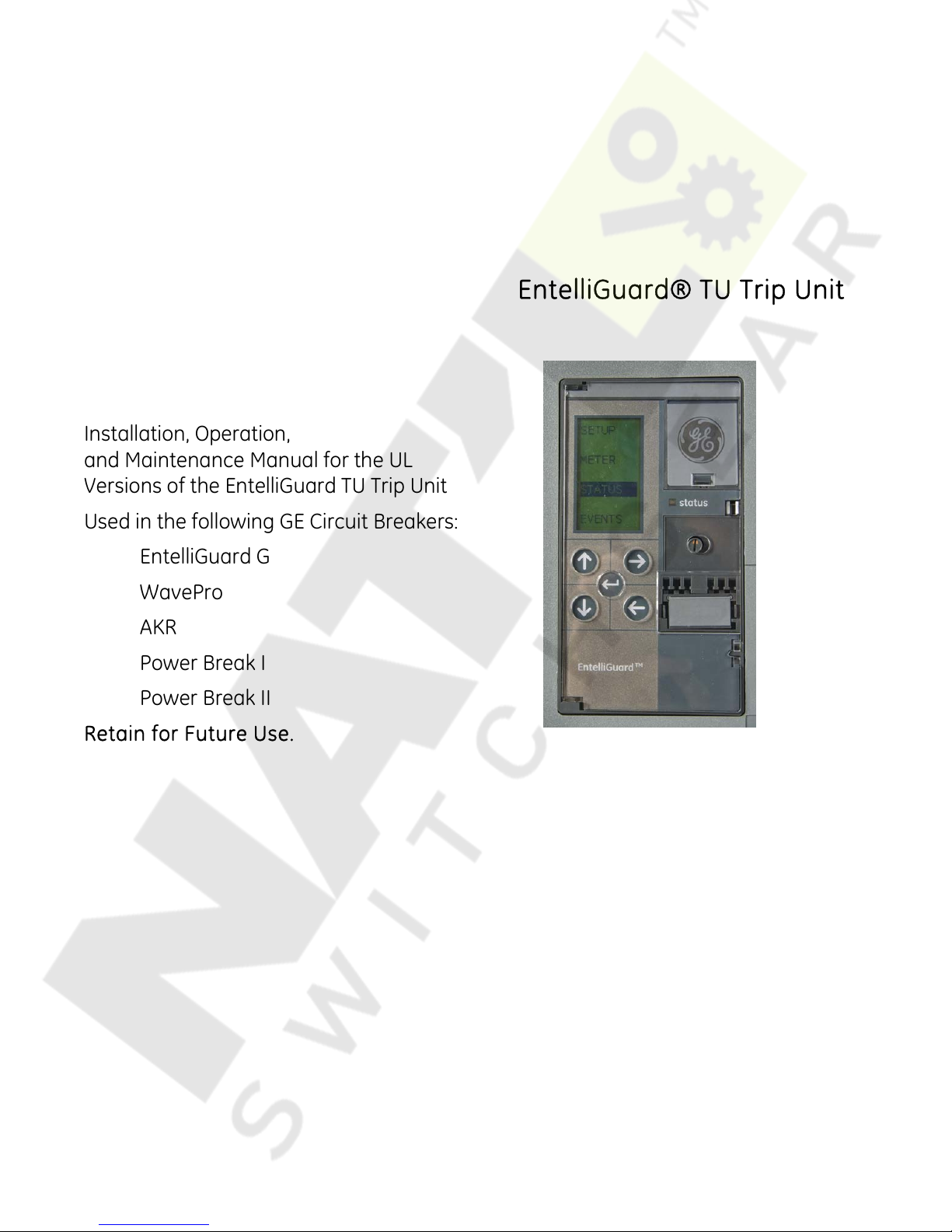
Installation, Operation,
and Maintenance Manual for the UL
Versions of the EntelliGuard TU Trip Unit
Used in the following GE Circuit Breakers:
EntelliGuard G
EntelliGuard® TU Trip Unit
WavePro
AKR
Power Break I
Power Break II
Retain for Future Use.
Page 2

Page 3
HAZARD CATEGORIES
The following important highlighted information appears
throughout this document to warn of potential hazards or
to call attention to information that clarifies a procedure.
Carefully read all instructions and become familiar with
the devices before trying to install, operate, service or
maintain this equipment.
DANGER
Indicates a hazardous situation that, if not avoided, will
result in death or serious injury.
WARNING
Indicates a hazardous situation which, if not avoided,
could result in death or serious injury.
CAUTION
Failure to comply with these instructions may result in
product damage.
NOTICE
Indicates important information that must be
remembered and aids in job performance
TRADEMARKS
The following are trademarks of GE Company:
EntelliGuard®
Power Break®
MicoVersaTrip®
ProTrip®
WARRANTY
This document is based on information available at the
time of its publication. While efforts have been made to
ensure accuracy, the information contained herein does
not cover all details or variations in hardware and
software, nor does it provide for every possible
contingency in connection with installation, operation,
and maintenance. Features may be described herein that
are not present in all hardware and software systems. GE
Electrical Distribution & Control assumes no obligation of
notice to holders of this document with respect to
changes subsequently made. GE Electrical Distribution &
Control makes no representation or warranty, expressed,
implied, or statutory, with respect to, and assumes no
responsibility for the accuracy, completeness, sufficiency,
or usefulness of the information contained herein. No
warrantees of merchantability or fitness for purpose shall
apply.
Contact your local sales office if further information is
required concerning any aspect of EntelliGuard G, AKR,
Power Break, Power Break II and
operation or maintenance.
WavePro circuit breaker
Page 4
EntelliGuard® TU Trip Unit
Table of Contents 09/25/08
TABLE OF CONTENTS
SECTION 1 – GENERAL INFORMATION.......................................................................................................................................................... 7
INTRODUCTION .............................................................................................................................................................. 7
ABBREVIATIONS AND ACRONYMS ........................................................................................................................ 7
PRODUCT DESCRIPTION ............................................................................................................................................ 7
Appearance ...................................................................................................................................................7
LCD Access..................................................................................................................................................... 7
Electrical Requirements ..........................................................................................................................8
Equipment Interfaces............................................................................................................................... 8
COMMUNICATIONS ...................................................................................................................................................... 8
Modbus ............................................................................................................................................................8
ProfiBus............................................................................................................................................................ 9
OVER CURRENT PROTECTION FUNCTIONS ...................................................................................................... 9
Long Time .......................................................................................................................................................9
Short Time ...................................................................................................................................................... 9
Adjustable Selective Instantaneous Protection........................................................................10
Reduced Energy Let-Through Instantaneous Protection (RELT)......................................10
Ground Fault Protection........................................................................................................................11
PROTECTIVE RELAY.....................................................................................................................................................12
Voltage Unbalance Relay .....................................................................................................................12
Current Unbalance Relay .....................................................................................................................12
Under Voltage Relay ...............................................................................................................................12
Under Voltage Relay Zero-Volt Trip Enable ................................................................................12
Over Voltage Relay ..................................................................................................................................12
Power-Reversal Relay ............................................................................................................................12
Power Direction Setup ...........................................................................................................................12
Potential Transformer Primary Voltage ........................................................................................12
Potential Transformer Connection..................................................................................................12
Power Demand Intervals......................................................................................................................13
Communication Address ......................................................................................................................13
Bell Alarm – Alarm Only/Bell Alarm with Lock-out Accessory Configuration Setup
(applies to Power Break II and WavePro Trip Units only).....................................................13
Settings Description ................................................................................................................................13
Input ................................................................................................................................................................13
Output.............................................................................................................................................................13
Current Alarm .............................................................................................................................................14
ZONE SELECT INTERLOCK .......................................................................................................................................14
ZSI Option .....................................................................................................................................................14
High Set Instantaneous Protection (HSIOC)................................................................................14
Making Current Release (MCR)...........................................................................................................14
POWER REQUIREMENTS ..........................................................................................................................................15
METERING FUNCTION ...............................................................................................................................................15
SECTION 2 – LIFTING, MOUNTING AND INSTALLATION.........................................................................................................................16
TRIP UNIT REMOVAL AND REPLACEMENT ......................................................................................................16
4 © 2008 General Electric All Rights Reserved
Power Break I and Power Break II Insulated Case Circuit Breakers ..............................16
WavePro Circuit Breakers ....................................................................................................................16
AKR (225 A to 5000 A Frames) Circuit Breakers........................................................................17
EntelliGuard Circuit Breaker Installation ......................................................................................18
Page 5
EntelliGuard®TU Trip Unit
09/25/08 Table of Contents
SECTION 3 – OPERATION................................................................................................................................................................................19
CIRCUIT BREAKER OPENING..................................................................................................................................19
WAVEFORM CAPTURE ..............................................................................................................................................19
EVENT LOGGING..........................................................................................................................................................19
LED STATUS INDICATOR ..........................................................................................................................................20
OPERATING MODES ...................................................................................................................................................20
SETUP MODE .................................................................................................................................................................21
Entering Setpoints into Memory.......................................................................................................21
Long Time Pickup .....................................................................................................................................21
Long Time Delay .......................................................................................................................................21
Short Time Pickup ....................................................................................................................................21
Short Time Delay ......................................................................................................................................21
Reduced Instantaneous Let-through Instantaneous Protection (RELT)...................... 21
Ground Fault Protection .......................................................................................................................22
Internal Residual Summation ............................................................................................................22
External Sensed Zero Sequence Input..........................................................................................22
Ground Fault Pickup Settings ............................................................................................................22
Ground Fault Time Delay Bands.......................................................................................................22
SECTION 4 – BATTERY......................................................................................................................................................................................23
GENERAL BATTERY INFORMATION.....................................................................................................................23
BATTERY FUNCTION ..................................................................................................................................................23
BATTERY REPLACEMENT.......................................................................................................................................... 23
SECTION 5 – MAINTENANCE AND TROUBLESHOOTING.........................................................................................................................24
MAINTENANCE .............................................................................................................................................................24
Rating Plug Removal and Replacement ......................................................................................24
TROUBLESHOOTING.................................................................................................................................................. 24
APPENDIX 1: COMMUNICATIONS PARAMETERS.......................................................................................................................................26
APPENDIX 2: OPERATING MODES AND FUNCTIONS SPECIFICS...........................................................................................................37
© 2008 General Electric All Rights Reserved 5
Page 6
EntelliGuard® TU Trip Unit
Table of Contents 09/25/08
TABLES
Table 1: Abbreviations and Acronyms ..................................................................................................................................................................................7
Table 2: Short Time Breaker Type and Frame...................................................................................................................................................................9
Table 3: Short Time Delay Slope Settings .........................................................................................................................................................................10
Table 4: Maximum Instantaneous for Power Break I, Power Break I, WavePro and AKR Trip Units.................................................10
Table 5: Maximum Instantaneous Thresholds for Power Break I, Power Break I, WavePro and AKR Trip Units........................11
Table 6: Ground Fault Pickup Settings...............................................................................................................................................................................11
Table 7: Sensor Settings and Ratings ................................................................................................................................................................................11
Table 8: Ground Fault Time Delay Bands, 50 Hz and 60Hz.....................................................................................................................................11
Table 9: Voltage Unbalanced Settings...............................................................................................................................................................................12
Table 10: Current Unbalance Settings ...............................................................................................................................................................................12
Table 11: Under Voltage Settings .........................................................................................................................................................................................12
Table 12: Over Voltage Settings ............................................................................................................................................................................................12
Table 13: Power Reversal Settings.......................................................................................................................................................................................12
Table 14: Input Assignments...................................................................................................................................................................................................13
Table 15: Output Configuration.............................................................................................................................................................................................13
Table 16: Metering Data ............................................................................................................................................................................................................15
Table 17: Trigger Waveform Capture Events .................................................................................................................................................................19
Table 18 LED Operation.............................................................................................................................................................................................................20
Table 19: Ground Fault Time Delay .....................................................................................................................................................................................22
Table 20: Minimum Pickup and Clear Time .....................................................................................................................................................................22
Table 21: Troubleshooting Guide..........................................................................................................................................................................................25
Table 22: Communications Parameters – Modbus Function 2 ............................................................................................................................26
Table 23: Communications Parameters – Modbus Function 3 ............................................................................................................................26
Table 24: Communications Parameters – Modbus Function 4 ............................................................................................................................32
Table 25: Communications Parameters – Modbus Function 5 ............................................................................................................................36
FIGURES
Figure 1: Front Panel View – Power Break II and WavePro Trip Units..................................................................................................................7
Figure 2: Front Panel View – Power Break I and AKR Trip Units..............................................................................................................................7
Figure 3: Front Panel View – EntelliGuard G Trip Units.................................................................................................................................................7
Figure 4: Trip Unit Keypad ...........................................................................................................................................................................................................8
Figure 5: Long Time Pickup Setting ........................................................................................................................................................................................9
Figure 6: Short Time Pickup Time Current Curve.............................................................................................................................................................9
Figure 7: Removing the Old Trip Unit ..................................................................................................................................................................................17
Figure 8: AKR Circuit Breaker with Trip Unit....................................................................................................................................................................17
Figure 9: Installing the New Trip Unit .................................................................................................................................................................................17
Figure 10: Trip Unit Removal Sequence, Step A............................................................................................................................................................18
Figure 11: Trip Unit Removal Sequence, Step B............................................................................................................................................................18
Figure 12: Trip Unit Removal Sequence, Step C............................................................................................................................................................18
Figure 13: Trip Unit Removal Sequence, Step D ...........................................................................................................................................................18
Figure 14: Operating Modes and Functions Overview ..............................................................................................................................................20
Figure 15: Five Function Keys.................................................................................................................................................................................................20
Figure 16: Rating Plug Removal ............................................................................................................................................................................................24
Figure 17: SETUP Mode ..............................................................................................................................................................................................................37
Figure 18: METER Mode (Wye and Delta Systems) ......................................................................................................................................................41
Figure 19: STATUS Mode ...........................................................................................................................................................................................................42
Figure 20: EVENTS Mode ...........................................................................................................................................................................................................42
6 © 2008 General Electric All Rights Reserved
Page 7
EntelliGuard®TU Trip Unit
09/25/08 Section 1 – General Information
SECTION 1 – GENERAL INFORMATION
INTRODUCTION
The EntelliGuard TU Trip Unit is an electronic device that
interfaces with a circuit breaker. It monitors the breaker
phase currents, neutral current and/or voltage and trips
the breaker in the event of an over-current or voltage
related condition. It also provides protective relay
functions, advanced metering, diagnostic features, and
communications. The Trip Unit can be removed or
replaced in the field by de-energizing and removing the
cover of the circuit breaker.
The Trip Unit also connects with the circuit breaker flux
shifter to provide the electromechanical tripping function.
A user interface is provided on the front panel to allow
adjustment of the Trip Unit’s parameters.
ABBREVIATIONS AND ACRONYMS
The abbreviations and acronyms in Table 1 used
throughout this manual. Slightly different abbreviations
and acronyms are used for IEC trip units.
Table 1: Abbreviations and Acronyms
Item Definition
I
RMS
xlCT
ln
PRODUCT DESCRIPTION
True RMS current measurement through a
phase
Multiples of current sensor rating (non-
dimensional)
Rating plug ampere setting where l
the breaker nominal rated current (A)
nlCT
. This is
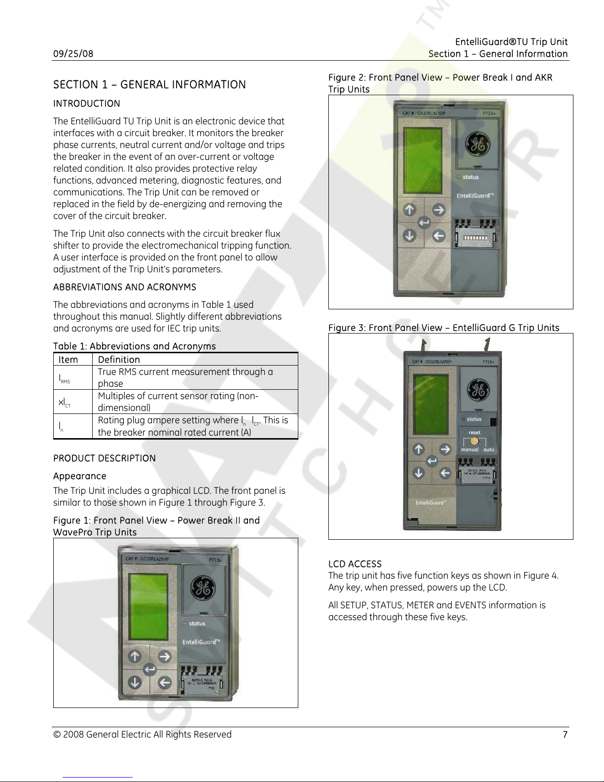
Figure 2: Front Panel View – Power Break I and AKR
Trip Units
Figure 3: Front Panel View – EntelliGuard G Trip Units
Appearance
The Trip Unit includes a graphical LCD. The front panel is
similar to those shown in Figure 1 through Figure 3.
Figure 1: Front Panel View – Power Break II and
WavePro Trip Units
LCD ACCESS
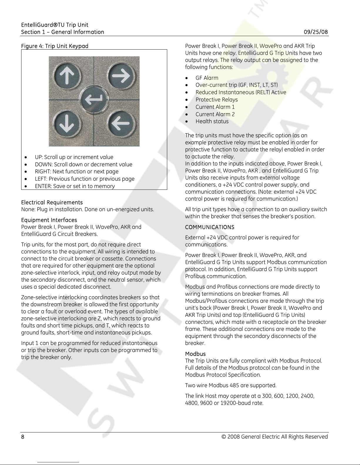
The trip unit has five function keys as shown in Figure 4.
Any key, when pressed, powers up the LCD.
All SETUP, STATUS, METER and EVENTS information is
accessed through these five keys.
© 2008 General Electric All Rights Reserved 7
Page 8
EntelliGuard®TU Trip Unit
Section 1 – General Information 09/25/08
Figure 4: Trip Unit Keypad
• UP: Scroll up or increment value
• DOWN: Scroll down or decrement value
• RIGHT: Next function or next page
• LEFT: Previous function or previous page
• ENTER: Save or set in to memory
Electrical Requirements
None: Plug in installation. Done on un-energized units.
Equipment Interfaces
Power Break I, Power Break II, WavePro, AKR and
EntelliGuard G Circuit Breakers.
Trip units, for the most part, do not require direct
connections to the equipment. All wiring is intended to
connect to the circuit breaker or cassette. Connections
that are required for other equipment are the optional
zone-selective interlock, input, and relay output made by
the secondary disconnect, and the neutral sensor, which
uses a special dedicated disconnect.
Zone-selective interlocking coordinates breakers so that
the downstream breaker is allowed the first opportunity
to clear a fault or overload event. The types of available
zone-selective interlocking are Z, which reacts to ground
faults and short time pickups, and T, which reacts to
ground faults, short-time and instantaneous pickups.
Input 1 can be programmed for reduced instantaneous
or trip the breaker. Other inputs can be programmed to
trip the breaker only.
Power Break I, Power Break II, WavePro and AKR Trip
Units have one relay. EntelliGuard G Trip Units have two
output relays. The relay output can be assigned to the
following functions:
• GF Alarm
• Over-current trip (GF, INST, LT, ST)
• Reduced Instantaneous (RELT) Active
• Protective Relays
• Current Alarm 1
• Current Alarm 2
• Health status
The trip units must have the specific option (as an
example protective relay must be enabled in order for
protective function to actuate the relay) enabled in order
to actuate the relay.
In addition to the inputs indicated above, Power Break I,
Power Break II, WavePro, AKR , and EntelliGuard G Trip
Units also receive inputs from external voltage
conditioners, a +24 VDC control power supply, and
communication connections. (Note: external +24 VDC
control power is required for communication.)
All trip unit types have a connection to an auxiliary switch
within the breaker that senses the breaker’s position.
COMMUNICATIONS
External +24 VDC control power is required for
communications.
Power Break I, Power Break II, WavePro, AKR, and
EntelliGuard G Trip Units support Modbus communication
protocol. In addition, EntelliGuard G Trip Units support
Profibus communication.
Modbus and Profibus connections are made directly to
wiring terminations on breaker frames. All
Modbus/Profibus connections are made through the trip
unit’s back (Power Break I, Power Break II, WavePro and
AKR Trip Units) and top (EntelliGuard G Trip Units)
connectors, which mate with a receptacle on the breaker
frame. These additional connections are made to the
equipment through the secondary disconnects of the
breaker.
Modbus
The Trip Units are fully compliant with Modbus Protocol.
Full details of the Modbus protocol can be found in the
Modbus Protocol Specification.
8 © 2008 General Electric All Rights Reserved
Two wire Modbus 485 are supported.
The link Host may operate at a 300, 600, 1200, 2400,
4800, 9600 or 19200-baud rate.
Page 9
EntelliGuard®TU Trip Unit
09/25/08 Section 1 – General Information
ProfiBus
This protocol is integral to EntelliGuard G Trip Units.
ProfiBus DP over RS485 is supported.
OVER CURRENT PROTECTION FUNCTIONS
The Trip Unit provides the following over current
protections:
• Long Time
• Short Time
• Instantaneous
• Reduce Let Through Energy Instantaneous (RELT)
• Ground Fault Internal Summation
• Ground Fault CT External Summation
• Override (HSIOC)
• Making Current Release (MCR)
Long Time
Long Time Pickup
This setpoint establishes the breaker's nominal ampere
rating, xLT, as a fraction of the rating plug value, xIn (xLT
= LT multiplier x xIn).
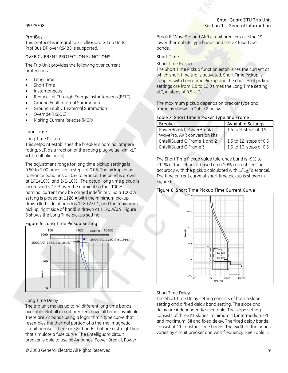
The adjustment range for long time pickup settings is
0.50 to 1.00 times xIn in steps of 0.05. The pickup value
tolerance band has a 10% tolerance. The band is drawn
at 1/(1+10%) and 1/1-10%). The actual long time pickup is
increased by 12% over the nominal so that 100%
nominal current may be carried indefinitely. So a 1000 A
setting is placed at 1120 A with the minimum pickup
drawn (left side of band) is 1120 A/1.1, and the maximum
pickup (right side of band) is drawn at 1120 A/0.9. Figure
5 shows the Long Time pickup setting.
Break II, WavePro and AKR circuit breakers use the 19
lower thermal CB-type bands and the 22 fuse-type
bands.
Short Time
Short Time Pickup
The Short Time Pickup function establishes the current at
which short time trip is activated. Short Time Pickup is
coupled with Long Time Pickup and the choices of pickup
settings are from 1.5 to 12.0 times the Long Time setting,
xLT, in steps of 0.5 xLT.
The maximum pickup depends on breaker type and
frame as shown in Table 2 below:
Table 2. Short Time Breaker Type and Frame
Breaker Available Settings
PowerBreak I, PowerBreak II,
1.5 to 9, steps of 0.5
WavePro, AKR conversion kits
EntelliGuard G Frame 1 and 2 1.5 to 12, steps of 0.5
EntelliGuard G Frame 3 1.5 to 10, steps of 0.5
The Short Time Pickup value tolerance band is -9% to
+11% of the set point based on a 10% current sensing
accuracy with the pickup calculated with 1/(1+
Tolerance).
The time current curve of short time pickup is shown in
Figure 6.
Figure 6: Short Time Pickup Time Current Curve
Figure 5: Long Time Pickup Setting
Long Time Delay
The trip unit makes up to 44 different long time bands
available. Not all circuit breakers have all bands available.
There are 22 bands using a logarithmic type curve that
resembles the thermal portion of a thermal magnetic
circuit breaker. There are 22 bands that are a straight line
that simulate a fuse curve. The Entelliguard circuit
breaker is able to use all 44 bands. Power Break I, Power
Short Time Delay
The Short Time Delay setting consists of both a slope
setting and a fixed delay band setting. The slope and
delay are independently selectable. The slope setting
consists of three I
2
T slopes (minimum (1), intermediate (2)
and maximum (3)) and fixed delay. The fixed delay bands
consist of 11 constant time bands. The width of the bands
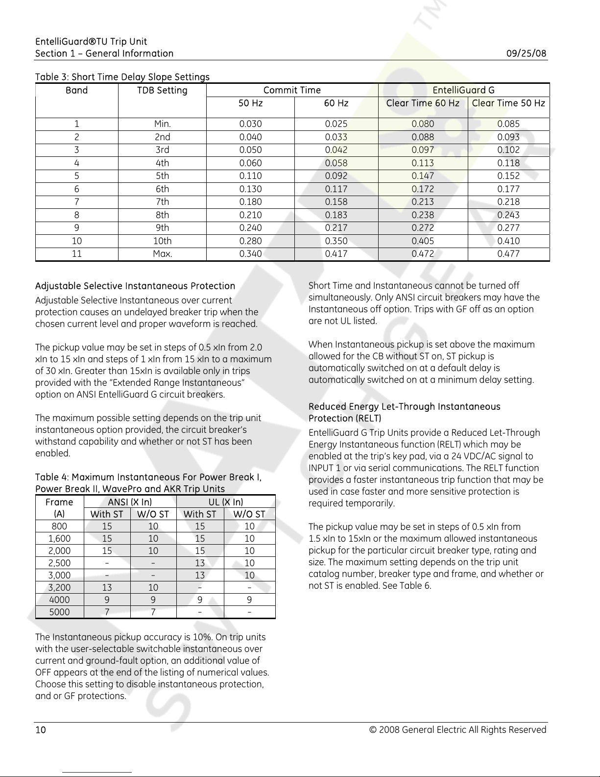
varies by circuit breaker and with frequency. See Table 3.
© 2008 General Electric All Rights Reserved 9
Page 10
EntelliGuard®TU Trip Unit
Section 1 – General Information 09/25/08
Table 3: Short Time Delay Slope Settings
Band TDB Setting
Commit Time EntelliGuard G
50 Hz 60 Hz Clear Time 60 Hz Clear Time 50 Hz
1 Min. 0.030 0.025 0.080 0.085
2 2nd 0.040 0.033 0.088 0.093
3 3rd 0.050 0.042 0.097 0.102
4 4th 0.060 0.058 0.113 0.118
5 5th 0.110 0.092 0.147 0.152
6 6th 0.130 0.117 0.172 0.177
7 7th 0.180 0.158 0.213 0.218
8 8th 0.210 0.183 0.238 0.243
9 9th 0.240 0.217 0.272 0.277
10 10th 0.280 0.350 0.405 0.410
11 Max. 0.340 0.417 0.472 0.477
Adjustable Selective Instantaneous Protection
Adjustable Selective Instantaneous over current
protection causes an undelayed breaker trip when the
chosen current level and proper waveform is reached.
The pickup value may be set in steps of 0.5 xIn from 2.0
xIn to 15 xIn and steps of 1 xIn from 15 xIn to a maximum
of 30 xIn. Greater than 15xIn is available only in trips
provided with the “Extended Range Instantaneous”
option on ANSI EntelliGuard G circuit breakers.
The maximum possible setting depends on the trip unit
instantaneous option provided, the circuit breaker’s
withstand capability and whether or not ST has been
enabled.
Table 4: Maximum Instantaneous For Power Break I,
Power Break II, WavePro and AKR Trip Units
Frame
(A)
800
ANSI (X In) UL (X In)
With ST W/O ST With ST W/O ST
15 10 15 10
1,600 15 10 15 10
2,000 15 10 15 10
2,500
3,000
3,200 13 10
- -
- -
13 10
13 10
- -
4000 9 9 9 9
5000 7 7
- -
The Instantaneous pickup accuracy is 10%. On trip units
with the user-selectable switchable instantaneous over
current and ground-fault option, an additional value of
OFF appears at the end of the listing of numerical values.
Choose this setting to disable instantaneous protection,
and or GF protections.
Short Time and Instantaneous cannot be turned off
simultaneously. Only ANSI circuit breakers may have the
Instantaneous off option. Trips with GF off as an option
are not UL listed.
When Instantaneous pickup is set above the maximum
allowed for the CB without ST on, ST pickup is
automatically switched on at a default delay is
automatically switched on at a minimum delay setting.
Reduced Energy Let-Through Instantaneous
Protection (RELT)
EntelliGuard G Trip Units provide a Reduced Let-Through
Energy Instantaneous function (RELT) which may be
enabled at the trip’s key pad, via a 24 VDC/AC signal to
INPUT 1 or via serial communications. The RELT function
provides a faster instantaneous trip function that may be
used in case faster and more sensitive protection is
required temporarily.
The pickup value may be set in steps of 0.5 xIn from
1.5 xIn to 15xIn or the maximum allowed instantaneous
pickup for the particular circuit breaker type, rating and
size. The maximum setting depends on the trip unit
catalog number, breaker type and frame, and whether or
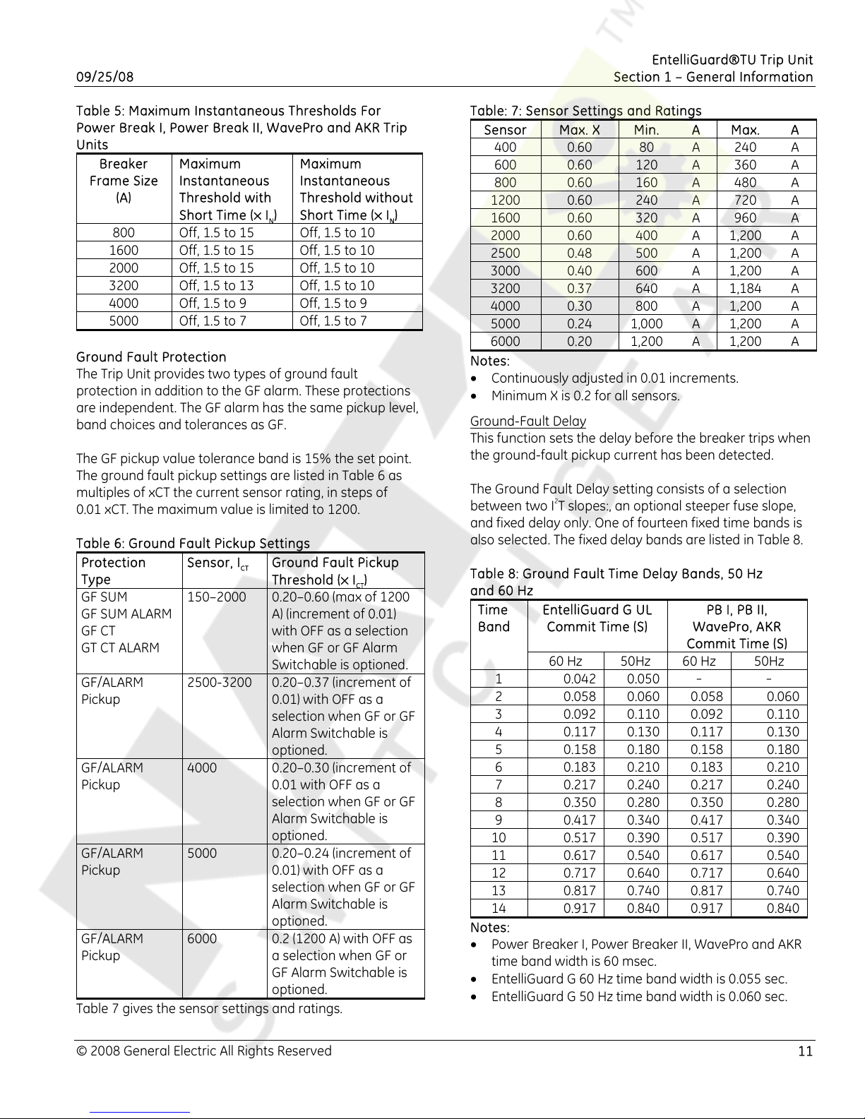
not ST is enabled. See Table 6.
10 © 2008 General Electric All Rights Reserved
Page 11
EntelliGuard®TU Trip Unit
09/25/08 Section 1 – General Information
Table 5: Maximum Instantaneous Thresholds For
Power Break I, Power Break II, WavePro and AKR Trip
Units
Breaker
Frame Size
(A)
800
Maximum
Instantaneous
Threshold with
Short Time (× I
Off, 1.5 to 15 Off, 1.5 to 10
Maximum
Instantaneous
Threshold without
)
Short Time (× IN)
N
1600 Off, 1.5 to 15 Off, 1.5 to 10
2000 Off, 1.5 to 15 Off, 1.5 to 10
3200 Off, 1.5 to 13 Off, 1.5 to 10
4000 Off, 1.5 to 9 Off, 1.5 to 9
5000 Off, 1.5 to 7 Off, 1.5 to 7
Ground Fault Protection
The Trip Unit provides two types of ground fault
protection in addition to the GF alarm. These protections
are independent. The GF alarm has the same pickup level,
band choices and tolerances as GF.
The GF pickup value tolerance band is 15% the set point.
The ground fault pickup settings are listed in Table 6 as
multiples of xCT the current sensor rating, in steps of
0.01 xCT. The maximum value is limited to 1200.
Table 6: Ground Fault Pickup Settings
Protection
Type
GF SUM
GF SUM ALARM
GF CT
GT CT ALARM
Sensor, I
150–2000 0.20–0.60 (max of 1200
Ground Fault Pickup
CT
Threshold (× I
)
CT
A) (increment of 0.01)
with OFF as a selection
when GF or GF Alarm
Switchable is optioned.
GF/ALARM
Pickup
2500-3200 0.20–0.37 (increment of
0.01) with OFF as a
selection when GF or GF
Alarm Switchable is
optioned.
GF/ALARM
Pickup
4000 0.20–0.30 (increment of
0.01 with OFF as a
selection when GF or GF
Alarm Switchable is
optioned.
GF/ALARM
Pickup
5000 0.20–0.24 (increment of
0.01) with OFF as a
selection when GF or GF
Alarm Switchable is
optioned.
GF/ALARM
Pickup
6000 0.2 (1200 A) with OFF as
a selection when GF or
GF Alarm Switchable is
optioned.
Table 7 gives the sensor settings and ratings.
Table: 7: Sensor Settings and Ratings
Sensor Max. X Min. A Max. A
400 0.60 80 A
240 A
600 0.60 120 A 360 A
800 0.60 160 A 480 A
1200 0.60 240 A 720 A
1600 0.60 320 A 960 A
2000 0.60 400 A 1,200 A
2500 0.48 500 A 1,200 A
3000 0.40 600 A 1,200 A
3200 0.37 640 A 1,184 A
4000 0.30 800 A 1,200 A
5000 0.24 1,000 A 1,200 A
6000 0.20 1,200 A 1,200 A
Notes:
• Continuously adjusted in 0.01 increments.
• Minimum X is 0.2 for all sensors.
Ground-Fault Delay
This function sets the delay before the breaker trips when
the ground-fault pickup current has been detected.
The Ground Fault Delay setting consists of a selection
between two I
2
T slopes:, an optional steeper fuse slope,
and fixed delay only. One of fourteen fixed time bands is
also selected. The fixed delay bands are listed in Table 8.
Table 8: Ground Fault Time Delay Bands, 50 Hz
and 60 Hz
Time
Band
EntelliGuard G UL
Commit Time (S)
PB I, PB II,
WavePro, AKR
Commit Time (S)
60 Hz 50Hz 60 Hz 50Hz
1 0.042 0.050
- -
2 0.058 0.060 0.058 0.060
3 0.092 0.110 0.092 0.110
4 0.117 0.130 0.117 0.130
5 0.158 0.180 0.158 0.180
6 0.183 0.210 0.183 0.210
7 0.217 0.240 0.217 0.240
8 0.350 0.280 0.350 0.280
9 0.417 0.340 0.417 0.340
10 0.517 0.390 0.517 0.390
11 0.617 0.540 0.617 0.540
12 0.717 0.640 0.717 0.640
13 0.817 0.740 0.817 0.740
14 0.917 0.840 0.917 0.840
Notes:
• Power Breaker I, Power Breaker II, WavePro and AKR
time band width is 60 msec.
• EntelliGuard G 60 Hz time band width is 0.055 sec.
• EntelliGuard G 50 Hz time band width is 0.060 sec.
© 2008 General Electric All Rights Reserved 11
Page 12
EntelliGuard®TU Trip Unit
Section 1 – General Information 09/25/08
PROTECTIVE RELAY
The protection relay can be set to either cause a trip or
an alarm. If the PR Enable on the LCD is set to ON, a trip
will be generated, if set to NO an alarm will be generated.
Voltage Unbalance Relay
This function compares the highest or lowest phase
voltage with the average of all three phases and initiates
a trip if the difference exceeds the set point.
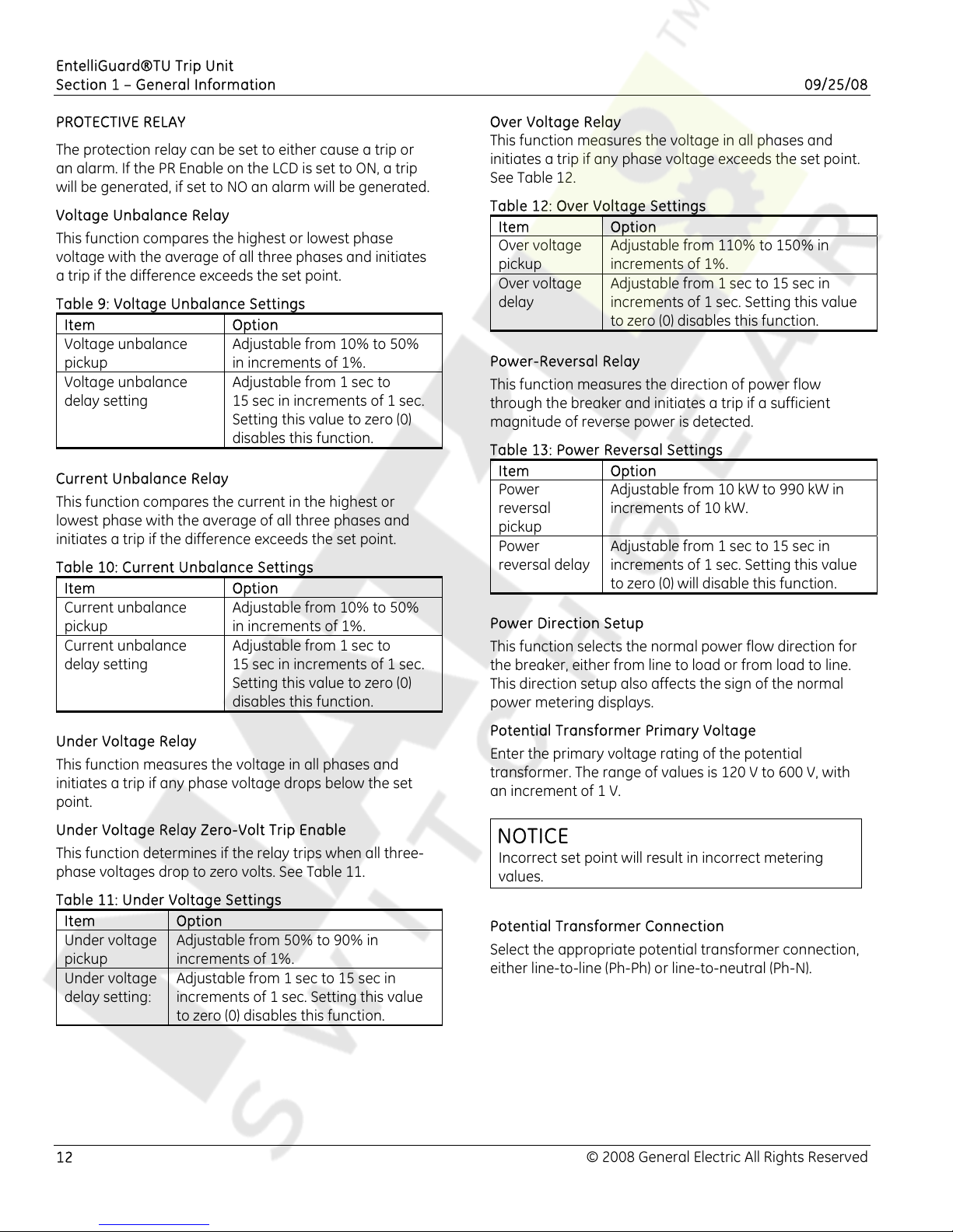
Table 9: Voltage Unbalance Settings
Item Option
Voltage unbalance
pickup
Voltage unbalance
delay setting
Current Unbalance Relay
This function compares the current in the highest or
lowest phase with the average of all three phases and
initiates a trip if the difference exceeds the set point.
Table 10: Current Unbalance Settings
Item Option
Current unbalance
pickup
Current unbalance
delay setting
Under Voltage Relay
This function measures the voltage in all phases and
initiates a trip if any phase voltage drops below the set
point.
Under Voltage Relay Zero-Volt Trip Enable
This function determines if the relay trips when all three-
phase voltages drop to zero volts. See Table 11.
Table 11: Under Voltage Settings
Item Option
Under voltage
pickup
Under voltage
delay setting:
Adjustable from 50% to 90% in
increments of 1%.
Adjustable from 1 sec to 15 sec in
increments of 1 sec. Setting this value
to zero (0) disables this function.
Adjustable from 10% to 50%
in increments of 1%.
Adjustable from 1 sec to
15 sec in increments of 1 sec.
Setting this value to zero (0)
disables this function.
Adjustable from 10% to 50%
in increments of 1%.
Adjustable from 1 sec to
15 sec in increments of 1 sec.
Setting this value to zero (0)
disables this function.
Over Voltage Relay
This function measures the voltage in all phases and
initiates a trip if any phase voltage exceeds the set point.
See Table 12.
Table 12: Over Voltage Settings
Item Option
Over voltage
pickup
Over voltage
delay
Power-Reversal Relay
This function measures the direction of power flow
through the breaker and initiates a trip if a sufficient
magnitude of reverse power is detected.
Table 13: Power Reversal Settings
Item Option
Power
reversal
pickup
Power
reversal delay
Power Direction Setup
This function selects the normal power flow direction for
the breaker, either from line to load or from load to line.
This direction setup also affects the sign of the normal
power metering displays.
Potential Transformer Primary Voltage
Enter the primary voltage rating of the potential
transformer. The range of values is 120 V to 600 V, with
an increment of 1 V.
Adjustable from 110% to 150% in
increments of 1%.
Adjustable from 1 sec to 15 sec in
increments of 1 sec. Setting this value
to zero (0) disables this function.
Adjustable from 10 kW to 990 kW in
increments of 10 kW.
Adjustable from 1 sec to 15 sec in
increments of 1 sec. Setting this value
to zero (0) will disable this function.
NOTICE
Incorrect set point will result in incorrect metering
values.
Potential Transformer Connection
Select the appropriate potential transformer connection,
either line-to-line (Ph-Ph) or line-to-neutral (Ph-N).
12 © 2008 General Electric All Rights Reserved
Page 13
EntelliGuard®TU Trip Unit
09/25/08 Section 1 – General Information
Power Demand Intervals
This function sets the power demand interval, which can
be in the range of 5 min to 60 min, in steps of 5 min. This
setpoint specifies the time interval for power demand
averaging.
Communication Address
The address options are from 1 to 254, in steps of 1 for
Modbus and Profibus communication protocols.
Bell Alarm-Alarm Only/Bell Alarm with Lock-out
Accessory Configuration Setup (applies to Power
Break II and WavePro Trip Units only)
This defines the types of signals (protection trip, Shunt
trip, Shunt Trip with Lockout, or Under Voltage Release
trip) that activate the Bell Alarm-Alarm Only and Bell
Alarm with Lockout accessories on the Power Break II
breaker only. The customer may enable or disable a
different path to activate these accessories from the
different types of trip signals.
The following settings can be set on the LCD or through
communication:
• Disabled
• Shunt Trip
• UVR Trip
• Over Current Trip
• Protective Relay Trip
• Shunt, UVR
• Shunt, Over Current
• Shunt, Protective Relay
• UVR, Over Current
• UVR, Protective Relay
• Over Current, Protective Relay
• Shunt Trip, UVR, Over Current
• Shunt, UVR, Protective Relay
• Shunt, Over Current, Protective Relay
• UVR, Over Current, Protective Relay
• Shunt, UVR, Over Current, Protective Relay
Settings Description
The following are descriptions of the effects of each
accessory switch when it is enabled:
If Bell Alarm or Bell Alarm with Lockout is set to Shunt
Trip, a fault generated by a Shunt Trip will cause the Bell
Alarm contacts to change state.
If Bell Alarm with Lock-out is set to over current trip, a
fault generated by LT, ST, GF, and/or Instantaneous will
cause the Bell Alarm contacts to change state.
Input
Inputs can be assigned to two main functionalities:
• Reduced Energy Let-Through (RELT)
• Trip the breaker
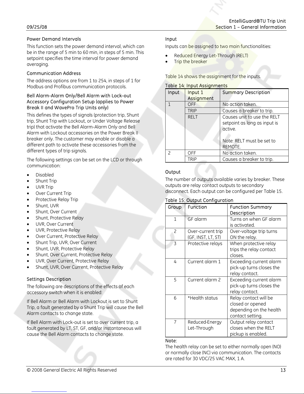
Table 14 shows the assignment for the inputs.
Table 14: Input Assignments
Input Input 1
Summary Description
Assignment
1
OFF No action taken.
TRIP Causes a breaker to trip.
RELT Causes unit to use the RELT
setpoint as long as input is
active.
Note: RELT must be set to
REMOTE.
OFF No action taken. 2
TRIP Causes a breaker to trip.
Output
The number of outputs available varies by breaker. These
outputs are relay contact outputs to secondary
disconnect. Each output can be configured per Table 15.
Table 15: Output Configuration
Group Function Function Summary
Description
1 GF alarm Turns on when GF alarm
is activated.
2 Over-current trip
(GF, INST, LT, ST)
Over-voltage trip turns
ON the relay.
3 Protective relays When protective relay
trips the relay contact
closes.
4 Current alarm 1 Exceeding current alarm
pick-up turns closes the
relay contact.
5 Current alarm 2 Exceeding current alarm
pick-up turns closes the
relay contact.
6 *Health status Relay contact will be
closed or opened
depending on the health
contact setting.
7 Reduced Energy
Let-Through
Output relay contact
closes when the RELT
pickup is enabled.
Note:
The health relay can be set to either normally open (NO)
or normally close (NC) via communication. The contacts
are rated for 30 VDC/25 VAC MAX, 1 A.
© 2008 General Electric All Rights Reserved 13
Page 14
EntelliGuard®TU Trip Unit
Section 1 – General Information 09/25/08
Current Alarm
The trip unit provides two types of current alarms:
Current Alarm 1 and Current Alarm 2.
The Current Alarm’s ON/OFF pickup settings are 0.5 to 1.0
xIn in steps of 0.05.
The trip unit does not allow the current alarm OFF
setpoint to be set above the ON threshold.
If the highest measured phase current goes above
Current Alarm 1 or Current Alarm 2 ON setpoint, and then
remains above the setpoint for more than 60 sec, the
output will close if assigned to either of these alarms.
If the current falls below the Current Alarm 1 or Current
Alarm 2 for more than 60 sec, the output, if assigned to
Current Alarm, will open.
ZONE SELECT INTERLOCK
The Zone Select Interlock (ZSI) function operates with a
group of series-connected breakers. The ZSI is achieved
with the use of the TIM module or an equivalent GE
qualified and recommended device.
ZSI Option
Per the trip unit catalog number there are two types of
zone-selective interlocking options:
• Z: reacts to ground faults and short time pickups.
• T: reacts to ground faults, short time and
instantaneous pickups. (Requires 24 VDC external
power be provided to the trip unit.)
The upstream breaker uses the ST ZSI and/or GF ZSI delay
bands and slope, and/or transition to a delay
Instantaneous if it receives a downstream ZSI signal.
The desired ZSI (ST and-or GF and-or Inst) must be
selected in order for the downstream breaker to issue a
ZSI signal, and the upstream breaker to act upon this
signal.
The ST ZSI Delay Bands are independent and have the
same bands available. Slope settings may also be
interlocked.
The GF ZSI Delay Bands are independent and have the
same bands available. Slope settings may also be
interlocked.
High Set Instantaneous Protection (HSIOC)
HSIOC is also Known as Override Pickup. Some of the trip
units on EntelliGuard G circuit breakers may be provided
with an override instantaneous trip.
Whether such a trip is provided or not depends on the
circuit breaker within which the trip is installed. If the
circuit breaker’s withstand (Icw) is equal to the short
circuit rating then the trip will not have an override
pickup. If the withstand rating is lower than the short
circuit rating then the trip will enable override protection
of the circuit breaker.
In UL 489 circuit breakers the HSIOC setting is nominally
at 107%of the Icw for the circuit breaker. Taking
tolerance into account, the override’s minimum trip is at
100% of the circuit breaker’s Icw.
In UL 1066 (ANSI) circuit breakers the HSIOC setting is
also at 107% Icw if the adjustable selective
instantaneous is ON. If the adjustable selective
instantaneous is OFF then the HSIOC nominal pick up is
at 98% of the circuit breaker’s Icw and, considering
tolerance, the minimum pickup is at 91% of the circuit
breaker’s Icw.
Power Break I, WavePro and AKR circuit breakers do not
employ an override function. PowerBreak II circuit
breakers use a mechanical override function.
Making Current Release (MCR)
Every EntelliGuard TU or EntelliGuard TU circuit breaker
uses a making current release. The making current
release varies per circuit breaker Envelope and is related
to the circuit breaker’s close and latch rating.
The MCR pickup is activated at the time the circuit
breaker closes and for six cycles thereafter. When the six
cycles are over, the threshold changes to the HSIOC
pickup setting.
14 © 2008 General Electric All Rights Reserved
Page 15
EntelliGuard®TU Trip Unit
09/25/08 Section 1 – General Information
POWER REQUIREMENTS
WARNING
IMPROPER INSTALLATION, OPERATION AND
MAINTENANCE
Ensure only qualified personnel install, operate, service
and maintain all electrical equipment.
Failure to comply with these instructions could
result in death or serious injury.
A small amount of power is necessary to energize the
liquid crystal display (LCD) during setup, for viewing
breaker status and for metering displays.
Power Break I, Power Break II, WavePro, AKR and
EntelliGuard G Trip Units require external +24 VDC control
power for communication
The power sources are:
• Current flow: Breaker current sensors provide
sufficient power to energize the LCD when at least
20% of the sensor's ampere rating is flowing.
• +24 VDC control power
• Internal battery power: Powers the unit temporarily
when any keypad key is pressed. Battery power
automatically turns off 20 sec after the last keypad
press. The battery power supply is disabled when any
current is sensed through the current sensors.
METERING FUNCTIONS
Table 16 shows the metering data provided by the trip
unit:
Table 16: Metering Data
Parameter Phase Unit
Current Phase A,B,C,
neutral
Voltage Phase L1, L2, L3
(Note 1)
Real Power Phase L1, L2, L3
and total
Reactive Power Phase L1, L2, L3
and total
Apparent
Power
Peak Power
Demand
Energy Phase A, B, C
Frequency
Power Factor
Notes:
• Potential transformers must be connected similar to
source (Wye or Delta). For Wye construction V=L-N
and for Delta construction V=L-L.
• Energy reset is supported from setup software and
over communications.
Phase L1, L2, L3
and total
Total Auto-ranging from
and total
-
-
A
V
kW
kVAR
kVA
0.00 kWH to 999
mW
Auto-ranging from
0.00 kWH to 999
mWH
Hz
%
© 2008 General Electric All Rights Reserved 15
Page 16
EntelliGuard® TU Trip Unit
Section 2 – Lifting, Mounting and Installation 09/25/08
SECTION 2 LIFTING, MOUNTING AND
INSTALLATION
DANGER
ELECTROCUTION
• Ensure the circuit breaker has been tripped,
indicating OFF and that applicable lock-out/tag-
out requirements are met and followed.
• Ensure the main springs are fully discharged.
• Do not touch the circuit breaker’s isolating
contacts during lifting.
Failure to comply with these instructions will result
in death or serious injury.
WARNING
IMPROPER INSTALLATION, OPERATION, SERVICE AND
MAINTENANCE
• Ensure only qualified personnel install, operate,
service and maintain all electrical equipment.
• Do not perform any maintenance, including
breaker charging, closing, tripping, or any other
function that could cause significant movement of
circuit breaker while it is on the draw-out
extension rails.
• Ensure circuit breaker is always left in the
CONNECTED, TEST or DISCONNECTED position to
avoid mispositioning of the breaker and flashback.
Failure to comply with these instructions could
result in death or serious injury.
WARNING
FALLING OBJECT
• Ensure lifting equipment has capability for device
being lifted.
• Wear hard hat, gloves and safety shoes.
Failure to comply with these instructions could
result in death or serious injury.
CAUTION
PRODUCT DAMAGE
• Ensure circuit breaker and its accessories are
always used within their designated ratings.
• Ensure the correct trip unit is paired with the
correct circuit breaker.
• Do not use excessive force when installing a trip
unit.
• Do not allow circuit breaker to hit a hard surface
while handling.
• Do not drag or slide circuit breaker across a hard
or rough surface.
Failure to comply with these instructions may
result in product damage.
TRIP UNIT REMOVAL AND REPLACEMENT
Power Break I, Power Break II, WavePro and AKR Trip
Units have rejection pins, installed on the rear of these
trip units, to prevent installation of an incorrect trip unit
into a breaker.
Replacement of a trip unit always requires repeating the
setup procedures
Power Break I and Power Break II Insulated Case
Circuit Breakers
The trip unit procedures for Power Break I and Power
Break II circuit breakers are very similar and are outlined
below. The EntelliGuard TU trip unit for a Power Break I is
different than that for a Power Break II (see Section 1).
Ensure the correct trip unit is used.
Trip Unit Removal
1. Loosen the four #8-32 screws on the circuit breaker
trim-plate assembly and remove the trim plate.
2. Loosen the four #10-32 screws at the corner of the
breaker cover. Remove the cover from the breaker
face.
3. Pull the trip unit locking lever to the right, then hold
the trip unit near the battery cover and lift it straight
out of the circuit breaker.
Trip Unit Reinstallation
1. Pull the trip unit locking lever to the right. While
holding the lever, carefully align the connector on the
rear of the trip unit with the connector in the breaker.
Press down on the trip unit while holding it near the
battery cover. When the trip unit is fully seated, slide
the locking lever back to the left.
2. Reinstall the breaker top cover and tighten the four
#10-32 screws to 32 in-lb.
3. Replace the trim plate and tighten the four #8-32
screws to 20 in-lb.
WavePro Circuit Breakers
Removal
1. Open the circuit breaker and remove it from the
2. For 800 A, 1600 A and 2000 A frame circuit breakers,
3. Depress the OPEN button to close the racking door.
4. Remove the wire forms and remove the trim plate
cubicle or substructure. Place it on a suitable work
surface.
insert the racking handle (catalog number
568B731G1) and move the racking mechanism to the
TEST position, as shown on the draw-out position
indicator.
from the breaker.
16 © 2008 General Electric All Rights Reserved
Page 17
EntelliGuard®TU Trip Unit
09/25/08 Section 2 – Lifting, Mounting and Installation
5. Remove the six ¼ hex head screws, securing the
escutcheon to the breaker (three at top and three at
bottom). Pull the manual-charging handle out part
way, and then slide off the escutcheon.
6. Pull out the locking side on the right of the trip unit
mounting plate, and then pull the trip unit out
carefully disengaging the pins on the rear connector.
7. Pull out the locking side on the right of the trip unit
mounting plate, and then pull the trip unit out
carefully disengaging the pins on the rear connector.
Reinstallation
1. Pull out the locking side on the right of the trip unit
mounting plate. Push the trip unit into place,
carefully, engaging the 50 pin connector and lining
up the rejection posts on the rear of the trip unit with
the holes in the mounting plate. Push the locking
slide to the left.
2. Ensure the breaker racking mechanism is still in the
TEST position. Pull the manual charging handle out
partway, and then slide the handle through the slot in
the escutcheon and move escutcheon into place.
Insert the six mounting screws and tighten to 14-20
in-lb.
3. Replace the trim plate around the escutcheon by
re-hooking the wire forms into the sides.
4. Insert the racking handle and return the racking
mechanism to the DISC position, as shown by the
draw-out position indicator.
5. Reinstall the circuit breaker into its cubical or
substructure.
AKR (225 A to 5000 A Frames) Circuit Breakers
1. Open the circuit breaker by pressing the red TRIP
button on the front of the breaker escutcheon.
2. Disconnect any secondary wire harnesses between
the breaker and the switchgear.
3. On draw-out breakers, rack the breaker all the way
out to the DISCONNECT position.
4. Follow the instructions on the label attached to the
PROGRAMMER RELEASE LEVER to remove the trip
unit. There are three types of mounting plates:
• Type 1: Push in the lever to release the trip unit.
• Type 2: Pull out the lever to release the trip unit
as shown in Figure 7.
• Type 3: Push down on the lever.
Figure 7: Removing the Old Trip Unit
5. If the breaker is equipped with a MicroVersaTrip® 9
trip unit, the 36-pin trip unit connector must be
removed and remounted on the adapter bracket
provided. Slide the connector out of the mounting
plate and install it on the adapter bracket, as shown
in Figure 8.
Figure 8: AKR Circuit Breaker without Trip Unit
6. Align the connectors and rejection pin and connect
the EntelliGuard TU to the circuit breaker, as shown in
Figure 9.
Figure 9: Installing the New Trip Unit
© 2008 General Electric All Rights Reserved 17
Page 18
EntelliGuard® TU Trip Unit
Section 2 – Lifting, Mounting and Installation 09/25/08
EntelliGuard G Circuit Breaker Installation
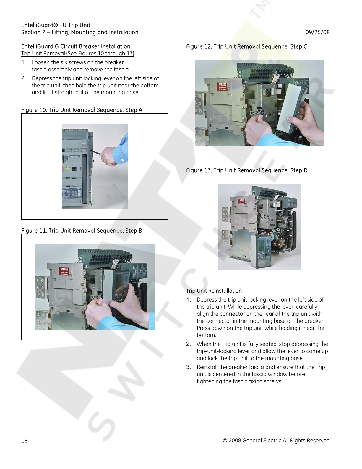
Trip Unit Removal (See Figures 10 through 13)
1. Loosen the six screws on the breaker
fascia assembly and remove the fascia.
2. Depress
the trip unit locking lever on the left side of
the trip unit, then hold the trip unit near the bottom
and lift it straight out of the mounting base.
Figure 10. Trip Unit Removal Sequence, Step A
Figure 11. Trip Unit Removal Sequence, Step B
Figure 12. Trip Unit Removal Sequence, Step C
Figure 13. Trip Unit Removal Sequence, Step D
Trip Unit Reinstallation
1. Depress the trip unit locking lever on the left side of
.
the trip unit
While depressing the lever, carefully
align the connector on the rear of the trip unit with
the connector in the mounting base on the breaker.
Press down on the trip unit while holding it near the
bottom.
2. When the trip unit is fully seated, stop depressing the
trip-unit-locking lever and allow the lever to come up
and lock the trip unit to the mounting base.
3. Reinstall the breaker fascia and ensure that the Trip
unit is centered in the fascia window before
tightening the fascia fixing screws.
18 © 2008 General Electric All Rights Reserved
Page 19
EntelliGuard®TU Trip Unit
09/25/08 Section 3 – Operation
SECTION 3 – OPERATION
WARNING
IMPROPER INSTALLATION, OPERATION AND
MAINTENANCE
Ensure only qualified personnel install, operate,
service and maintain all electrical equipment.
Failure to comply with these instructions could
result in death or serious injury.
WARNING
PERSONAL INJURY
• Avoid risk of injury from moving parts while
handling the circuit breaker.
• If advisable, use a cable/busbar lockable
grounding device (optional accessory) to provide
additional safety during system maintenance.
Failure to comply with these instructions could
result in death or serious injury.
CAUTION
PRODUCT DAMAGE
• Ensure circuit breaker and its accessories are
always used within their designated ratings.
• Use the specially designed circuit breaker
handling truck (optional accessory) when
removing the circuit breaker from its cassette.
Failure to comply with these instructions may
result in product damage.
NOTICE
• Each charging action provides sufficient charge
for an Open-Close-Open Operation without
requiring additional charging.
• The mechanism works properly only when the
circuit breaker is mounted on a horizontal plane
with bottom mounting or on vertical plane with
front mounting.
CIRCUIT BREAKER OPENING
NOTICE
Tripping under fault conditions will be automatic
depending on the protective device installed and its
settings.
24 V external power is required for this feature.
When waveform capture is executed, the following
channels will be captured simultaneously: Phase A
current, Phase B Current, Phase C Current, Phase L1
voltage, Phase L2 voltage, Phase L3 voltage. See Table 17.
Table 17: Trigger Waveform Capture Events
Event Waveform Capture
Setpoint
Manual trigger over
communications
Over current (GF, ST, LT, Inst) ON, OFF
Protective relays ON, OFF
Current alarm 1 ON, OFF
Current alarm 2 ON, OFF
EVENT LOGGING
The trip unit keeps a log of the last 10 events:
• Over current trips
• Protective relay trips
• Shunt trip (PBII and Global EntelliGuard G Trip Units
Only)
• Under voltage Release trip (PBII and Global
EntelliGuard G Trip Units Only)
• BIM Trip Unit Mismatch - Breaker Interface Module
The following information is stored with each event:
• RMS currents
Phase
•
• Type of trip
• Trip counter
• Time and date stamps
Trips are logged under self power without time stamp.
Events with time stamps are only logged when 24 V
control power is available.
All setup, status and metering information is accessed
through five keys whose functions are:
• Up: Scroll up or increment value
• Down: Scroll down or decrement value
• Right: Next function or next page
• Left: Previous function or previous page
• Enter: Save or setting in to memory
ON, OFF
WAVEFORM CAPTURE
A total of eight cycles are captured:
• Four pre-trigger.
• Four post-trigger.
© 2008 General Electric All Rights Reserved 19
Page 20
EntelliGuard® TU Trip Unit
Section 3 – Operation 09/25/08
LED STATUS INDICATOR
Table 18 shows the operation of the green LED located on
the front of the trip unit.
Table 18: LED Operation
Power Break I and
LED Status
AKR Trip Units
Status
Normal ON-OFF-ON-OFF (OFF for 2 sec)
Error ON-OFF-ON-OFF-ON-OFF
(OFF for 2 sec)
Trip ON-OFF (OFF for 2 sec)
Pickup ON-OFF-ON-OFF-ON-OFF-ON-OFF
(continuous)
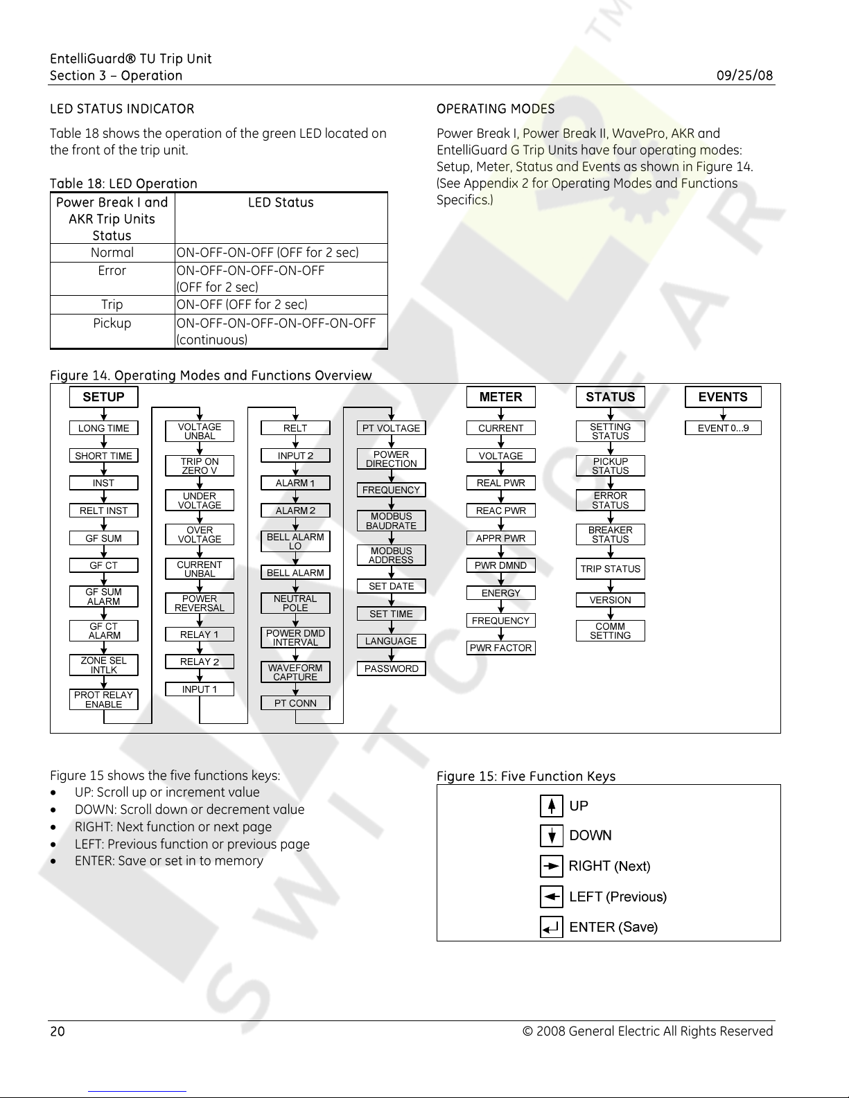
Figure 14. Operating Modes and Functions Overview
OPERATING MODES
Power Break I, Power Break II, WavePro, AKR and
EntelliGuard G Trip Units have four operating modes:
Setup, Meter, Status and Events as shown in Figure 14.
(See Appendix 2 for Operating Modes and Functions
Specifics.)
Figure 15 shows the five functions keys:
• UP: Scroll up or increment value
• DOWN: Scroll down or decrement value
• RIGHT: Next function or next page
• LEFT: Previous function or previous page
• ENTER: Save or set in to memory
20 © 2008 General Electric All Rights Reserved
Figure 15: Five Function Keys
Page 21
EntelliGuard®TU Trip Unit
09/25/08 Section 3 – Operation
SETUP MODE
SETUP Mode programming must be performed with the
rating plug installed.
These procedures apply to all trip units.
SETUP procedures should only be repeated if the trip unit
or the protection characteristics are changed, requiring
different set points and time-delays.
All trip units provide long time over current protection,
long time delay, and some form of instantaneous over
current protection when installed in circuit breakers. All
other functions are optional.
If a specific set of trip unit functions, such as relaying or
short time over-current protection, has not been ordered,
that function will not appear on the trip unit display.
Ignore setup mode instructions for such functions. The
trip unit must be provided with control power during
SETUP. Power can come from internal battery power,
from an external +24 VDC power supply, or by energizing
the breaker to at least 20% of its sensor load.
• Press UP or DOWN until the SETUP mode is selected.
• Press RIGHT or LEFT to access the functions in the
SETUP mode.
• Press ENTER to save desired values.
• Press RIGHT to advance to the next function.
Entering Setpoints into Memory
1. Press UP or DOWN to select SETUP.
2. Press LEFT to select the desired protection to change.
3. Press UP or DOWN to change values. The values will
start flashing.
4. Press ENTER to store the value into the memory. The
displayed value stops flashing and the save icon
appears on the top of the LCD. This indicates that the
value has been stored in memory and is active.
5. Confirm settings on the trip unit after making
changes by exiting and re-entering SETUP mode and
rechecking each changed setting.
Long Time Pickup
The first SETUP mode display is always the Long Time
Pickup setpoint. This setpoint establishes the breaker's
nominal ampere rating, xLT, as a fraction of the rating
plug value, xIn (xLT = LT multiplier x xIn).
The Long Time Pickup settings are 0.50 to 1.00 times xIn
in steps of 0.05. The pickup value tolerance band is -10%
to +10% of the set point. An additional accuracy
degradation of ±5% is allowed for waveforms with
significant harmonic distortion.
Long Time Delay
The EntelliGuard trip unit offers up to 44 long time delay
bands. Twenty-two have steep fuse-like shape and 22
have a logarithmic curve to a straight I
2
T slope shape.
This second shape is similar to that of the thermal
element of a thermal magnetic circuit breaker.
EntelliGuard G circuit breakers use all 44 bands. WavePro,
AKR and both PowerBreak devices use the lower 19 of the
curved thermal-type bands. To see the bands and the
range of settings, see the TCCs in the Application Guide
available at wwwgeelectrical.com/industrial.
Short Time Pickup
The Short Time Pickup function establishes the current at
which short time trip is activated. Short Time Pickup is
coupled with Long Time Pickup and the choices of pickup
settings are from 1.5 to 12.0 times the long time setting,
xLT, in steps of 0.5 xLT.
The ST pickup value tolerance band is -10% to +10% of
the set point. An additional accuracy degradation of ±5%
shall be allowed for waveforms with significant harmonic
distortion
Short Time Delay
The Short Time Delay function consists of both a slope
setting and a fixed delay band setting. The slope and
delay are independently selectable. The slope setting
consists of three I
2
T slopes (1, 2, 3) and fixed delay. The
fixed delay bands consist of 15 constant time bands
Reduced Instantaneous Let-Through Instantaneous
Protection (RELT)
The EntelliGuard TU Trip Unit provides a second user
settable and user-selectable instantaneous protection
algorithm. This protection is referred to as the RELT
pickup.
This protection enables an instantaneous protection
mode that may be set separately from the “Adjustable
Selective Instantaneous” and is a bit faster. The RELT
instantaneous pickup may be set by the user to a value
from 1.5X trip rating plug up to 15X trip rating plug in
some circuit breakers.
The user may also enable the function “ON” or “OFF” at
the HMI, as well as set it to remote. In the “remote” mode
the trip unit is able to receive a command via serial
communication (Modbus or Profibus) or a hardwired 24 V
AC or DC signal to enable the RELT protection on. If the
RELT protection is ON via any of the three ways it must be
turned off that same way.
When the trip unit receives a RELT on signal the RELT
instantaneous setting is enabled. If the RELT pick up
setting is lower than the adjustable selective
instantaneous setting the RELT setting will take
precedence.
© 2008 General Electric All Rights Reserved 21
Page 22
EntelliGuard® TU Trip Unit
Section 3 - Operation 09/25/08
Ground Fault Protection
The EntelliGuard TU Trip Unit can provide ground fault
protection in two different ways:
• via an internal summation scheme that adds up the
three phase current phasors, and if provided also the
neutral current phasor.
• Via an external zero sequence current signal from a
CT or a residual sum using iron core CTs.
Internal Residual Summation
The EntelliGuard trip unit uses internal air core sensors for
current sensing and the signals are residually summed
using advanced digital electronics. A neutral sensor may
be located remotely and connected to the trip unit. The
connection is limited to 10 m (33 ft).
Due to the air core sensor’s ability to handle a wide range
of primary currents without distortion, ground fault
sensing is accurate for a wide range of phase and current
inputs.
External Sensed Zero Sequence Input
The EntelliGuard trip unit can accept input from an externally
calculated ground fault current. The ground fault current
may be derived using a single zero sequence CT or multiple
phase CTs.
External CE marked zero sequence or ground return CTs
are available for IEC applications, but are not UL Listed.
Phase CTs used for a summation connection are UL
Listed. Applications for this capability include sensing at
the ground return connection for a transformer or
generator as well as application in multiple source
grounded systems.
Ground Fault Pickup Settings
All UL 489 and UL 1066 circuit breakers are limited to a
maximum nominal pick up setting of 1200 A per the
National Electrical Code or 60% of the sensor size,
whichever is lower. The minimum setting is 20% of sensor
size.
Ground Fault Time Delay Bands
Ground fault time delay bands used in the EntelliGuard G
circuit breakers range from 42 msec to 942 msec. In
Power Break I, Power Break II, WavePro and AKR circuit
breakers, the minimum GF time delay band is 58 msec
and the maximum is 417 msec. See Table 19.
Table 19: Ground Fault Time Delay
Sensor Minimum Maximum
400 0.2 0.60
600 0.2 0.60
800 0.2 0.60
1200 0.2 0.60
1600 0.2 0.60
2000 0.2 0.60
2500 0.2 0.48
3000 0.2 0.40
3200 0.2 0.37
4000 0.2 0.30
5000 0.2 0.24
6000 0.2 0.20
Notes:
• Continuously adjusted in 0.01 increments.
• Connected in a residual summation scheme.
The available minimum settings per circuit breaker type are
shown in Table 21. The maximum time delay band setting
for all circuit breakers is 0.940 sec with a 1 sec clear. See
Table 20.
Table 20: Minimum Pickup and Clear Time
Characteristic Power Break I
EntelliGuard G
Power Break II,
WavePro, AKR
Minimum Pickup 0.058 sec 0.042 sec
Minimum Clear
-
0.097 sec
Maximum Pickup 0.417 sec 0.940 sec
Maximum Clear
-
1.000 sec
The ground fault function may be shaped as a definite
time function (pickup and delay), an I
or a distinct double slope function designed to optimize
coordination. The I
4
T slope provides easier selectivity with
2
T slope an I4T slope
downstream fuses. The double knee GF curve facilitates
selectivity with downstream devices.
22 © 2008 General Electric All Rights Reserved
Page 23
EntelliGuard®TU Trip Unit
09/25/08 Section 4 – Battery
SECTION 4 – BATTERY
GENERAL BATTERY INFORMATION
The trip unit has a front pane-mounted battery. When the
battery is present, the user scan view data on the LCD
and read or program the trip unit via the keypads. The
battery allows the user to display data, change set points
and provide thermal memory.
The battery does not allow normal trip unit operation; i.e.
over current protection, alarms, relays, etc., are not
functional when the trip unit is powered from the battery.
The trip unit will automatically shut off after 20 sec when
battery powered to maximize battery life.
BATTERY FUNCTION
Pressing any key on the face of the trip unit powers the
unit from its internal battery. Battery power is maintained
for 20 sec after the last key is pressed.
This self-powered mode allows setting up the trip unit or
viewing trip targets when the breaker is de-energized and
external control power is unavailable.
All normal setup, meter, and status functions can be
performed with battery power.
NOTICE
For temperatures above 40° C, any key may have to
be held down for up to 5 sec for the trip unit to be
powered.
BATTERY REPLACEMENT
WARNING
IMPROPER REPLACEMENT
• Replace the battery with 3.6 V ½ AA lithium battery
only.
Wear hard hat, gloves and safety shoes when
•
replacing the battery.
Failure to comply with these instructions could
result in death or serious injury.
WARNING
IMPROPER DISPOSAL
• Ensure battery is properly disposed of according to
all applicable regulations.
Failure to comply with these instructions could
result in death or serious injury.
Replace the battery if it does not power up the trip unit
when any key is pressed.
Lift the battery cover on the front of the trip unit to
expose the 3.6 V ½ AA lithium cell. A suitable replacement
is TADIRAN part number TLL-5902/S or SANYO part
number CR14250SEwhich are commonly available from
most electrical stores or industrial distributors.
© 2008 General Electric All Rights Reserved 23
Page 24
EntelliGuard®TU Trip Unit
Section 5 – Maintenance and Troubleshooting 09/25/08
SECTION 5– MAINTENANCE AND
TROUBLESHOOTING
DANGER
ELECTROCUTION
Ensure the circuit breaker has been tripped, indicating
OFF, and the main springs are fully discharged when
performing circuit breaker maintenance.
Failure to comply with these instructions could result
in death or serious injury.
WARNING
IMPROPER INSTALLATION, OPERATION AND
MAINTENANCE
Ensure only qualified personnel install, operate, service
and maintain all electrical equipment.
Failure to comply with these instructions could result
in death or serious injury.
WARNING
PERSONAL INJURY
• Avoid risk of injury from moving parts while handling
the circuit breaker.
• If advisable, use a cable/busbar lockable grounding
device (optional accessory) to provide additional
safety during system maintenance.
Failure to comply with these instructions could result
in death or serious injury.
Figure 16: Rating Plug Removal
TROUBLESHOOTING
Table 21 provides procedures for troubleshooting and
isolating common problems. It does not cover every
possible condition.
Contact Post Sales Service at 1-888-GE-Resolve or 1-888-
437-3765 if these procedures doe not resolve the
problem.
MAINTENANCE
Rating Plug Removal and Replacement
NOTICE
Removal of the rating plug while the breaker is carrying
current reduces the breaker's current-carrying capacity
to approximately 40% of the current sensor rating.
Interchangeable rating plugs are removed with a Rating
Plug Extractor, Catalog No. TRTOOL. (Suitable equivalents
are commercially available as "integrated circuit (DIP)
extractors.") Grasp the rating plug tabs with the extractor
and pull the plug out as shown in Figure 16.
Be sure to grab the tabs and not the front cover of the
rating plug, or the plug may be damaged.
24 © 2008 General Electric All Rights Reserved
Page 25
EntelliGuard®TU Trip Unit
09/25/08 Section 5– Maintenance and Troubleshooting
Table 21: Troubleshooting Guide
The trip unit display is blank. External +24 VDC is absent.
The load current fluctuates near 20% of
the breaker sensor rating.
At least 20% of the current sensor rating,
(xCT) must be flowing through the breaker
to activate the display.
If not, power the trip unit with the internal
battery.
The battery power supply is disabled
when any current is sensed through the
current sensors.
Check that the control power supply is
present and operational.
The trip unit display E02.
BIM error.
No communication with the BIM
Check the BIM harness.
Mismatch trip unit / BIM option
The trip unit display E03. Memory failure.
The trip unit display E06. Internal failure.
The trip unit display E08. Invalid rating plug.
Return the unit to GE.
Return the unit to GE.
Check the rating plug. The rating plug
value shall not exceed and be below 40%
of the breaker sensor.
Ensure the rating plug is properly sited.
Unit does not communicate with
the Master.
The communication wires are shorted
or improperly connected.
Incorrect baud rate.
Incorrect address.
Locate and repair the short or the
incorrect connection.
Check that the baud rate assigned to the
trip unit, agrees with the baud rate at the
host.
Check that the address assigned to the
trip unit, agrees with the address at the
host.
Current readings are incorrect. Incorrect rating plug value.
Check the rating plug label.
Voltage readings are incorrect. The potential transformer (PT) primary
voltage was defined incorrectly.
The PT connection was defined
incorrectly.
Read the PT primary rating from the PT
name plate and set trip unit PT to this
value.
Set the trip unit phase to phase PH-PH or
phase to neutral PH-N according to the
system.
The display is blank or the Low
Battery symbol appears when the
BATTERY key is pressed.
Line current is below 20% of the
The battery is discharged.
The battery was stored too long with no
power applied to the trip unit.
Replace the battery.
Power the trip unit with external power or
by energizing the breaker for several days
to freshen the battery.
breaker sensor rating.
© 2008 General Electric All Rights Reserved 25
Page 26
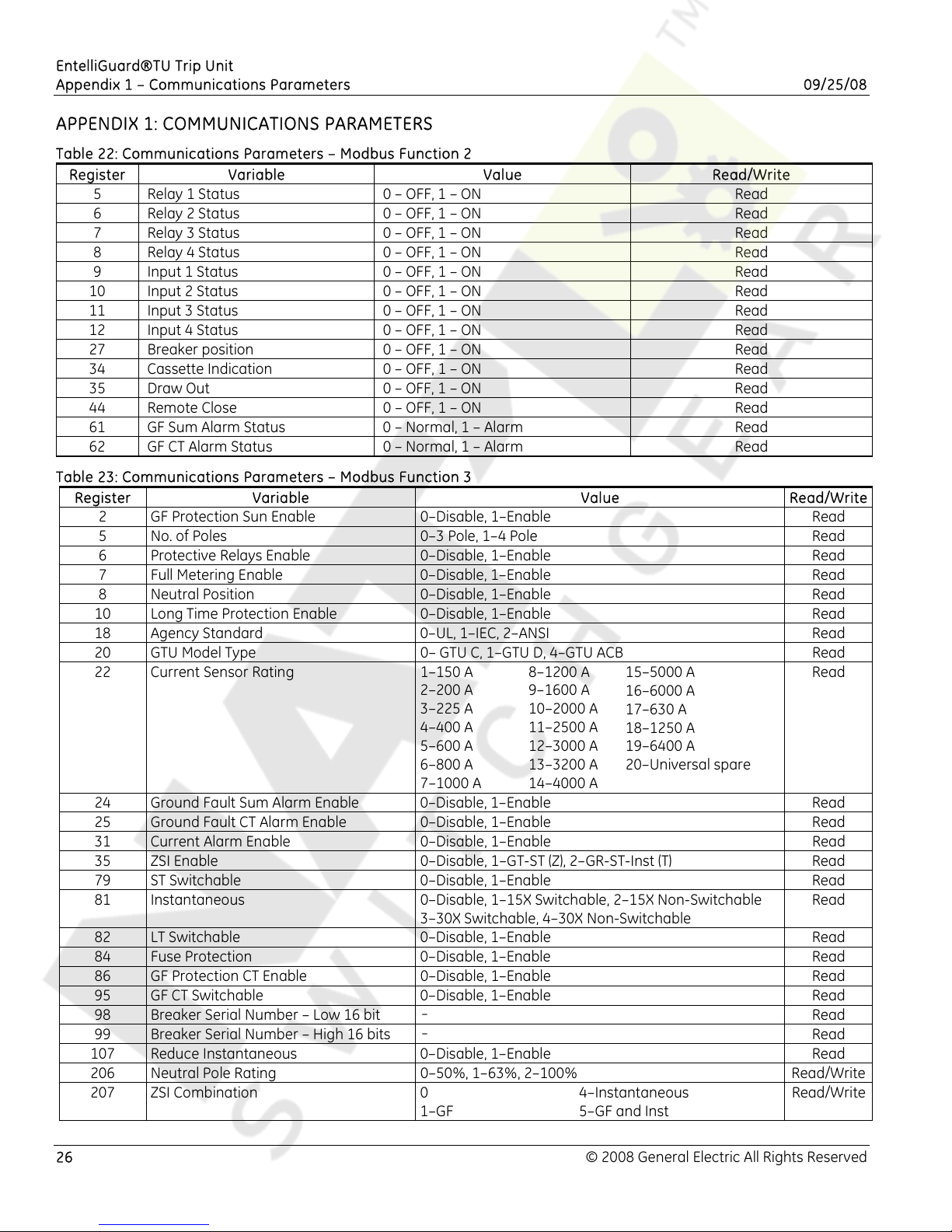
EntelliGuard®TU Trip Unit
Appendix 1 – Communications Parameters 09/25/08
APPENDIX 1: COMMUNICATIONS PARAMETERS
Table 22: Communications Parameters – Modbus Function 2
Register Variable Value Read/Write
5 Relay 1 Status 0 – OFF, 1 – ON Read
6 Relay 2 Status 0 – OFF, 1 – ON Read
7 Relay 3 Status 0 – OFF, 1 – ON Read
8 Relay 4 Status 0 – OFF, 1 – ON Read
9 Input 1 Status 0 – OFF, 1 – ON Read
10 Input 2 Status 0 – OFF, 1 – ON Read
11 Input 3 Status 0 – OFF, 1 – ON Read
12 Input 4 Status 0 – OFF, 1 – ON Read
27 Breaker position 0 – OFF, 1 – ON Read
34 Cassette Indication 0 – OFF, 1 – ON Read
35 Draw Out 0 – OFF, 1 – ON Read
44 Remote Close 0 – OFF, 1 – ON Read
61 GF Sum Alarm Status 0 – Normal, 1 – Alarm Read
62 GF CT Alarm Status 0 – Normal, 1 – Alarm Read
Table 23: Communications Parameters – Modbus Function 3
Register Variable Value Read/Write
2 GF Protection Sun Enable 0–Disable, 1–Enable Read
5 No. of Poles 0–3 Pole, 1–4 Pole Read
6 Protective Relays Enable 0–Disable, 1–Enable Read
7 Full Metering Enable 0–Disable, 1–Enable Read
8 Neutral Position 0–Disable, 1–Enable Read
10 Long Time Protection Enable 0–Disable, 1–Enable Read
18 Agency Standard 0–UL, 1–IEC, 2–ANSI Read
20 GTU Model Type 0– GTU C, 1–GTU D, 4–GTU ACB Read
22 Current Sensor Rating 1–150 A
2–200 A
3–225 A
4–400 A
5–600 A
6–800 A
7–1000 A
24 Ground Fault Sum Alarm Enable 0–Disable, 1–Enable Read
25 Ground Fault CT Alarm Enable 0–Disable, 1–Enable Read
31 Current Alarm Enable 0–Disable, 1–Enable Read
35 ZSI Enable 0–Disable, 1–GT-ST (Z), 2–GR-ST-Inst (T) Read
79 ST Switchable 0–Disable, 1–Enable Read
81 Instantaneous 0–Disable, 1–15X Switchable, 2–15X Non-Switchable
3–30X Switchable, 4–30X Non-Switchable
82 LT Switchable 0–Disable, 1–Enable Read
84 Fuse Protection 0–Disable, 1–Enable Read
86 GF Protection CT Enable 0–Disable, 1–Enable Read
95 GF CT Switchable 0–Disable, 1–Enable Read
98 Breaker Serial Number – Low 16 bit
99 Breaker Serial Number – High 16 bits
107 Reduce Instantaneous 0–Disable, 1–Enable Read
206 Neutral Pole Rating 0–50%, 1–63%, 2–100% Read/Write
207 ZSI Combination 0
-
-
1–GF
8–1200 A
9–1600 A
10–2000 A
11–2500 A
12–3000 A
13–3200 A
14–4000 A
4–Instantaneous
5–GF and Inst
15–5000 A
16–6000 A
17–630 A
18–1250 A
19–6400 A
20–Universal spare
Read
Read
Read
Read
Read/Write
26 © 2008 General Electric All Rights Reserved
Page 27
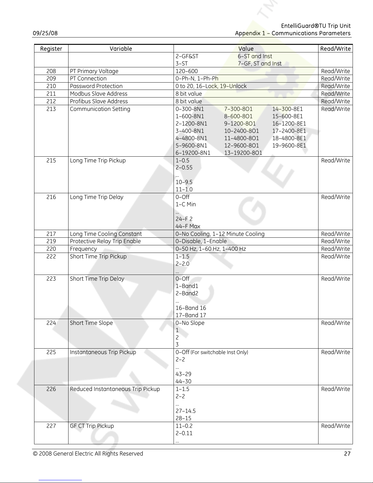
EntelliGuard®TU Trip Unit
09/25/08 Appendix 1 – Communications Parameters
Register Variable Value Read/Write
2–GF&ST
3–ST
6–ST and Inst
7–GF, ST and Inst
208 PT Primary Voltage 120–600 Read/Write
209 PT Connection 0–Ph-N, 1–Ph-Ph Read/Write
210 Password Protection 0 to 20, 16–Lock, 19–Unlock Read/Write
211 Modbus Slave Address 8 bit value Read/Write
212 Profibus Slave Address 8 bit value Read/Write
213 Communication Setting 0–300-8N1
1–600-8N1
2–1200-8N1
3–400-8N1
4–4800-8N1
5–9600-8N1
6–19200-8N1
215 Long Time Trip Pickup 1–0.5
7–300-8O1
8–600-8O1
9–1200-8O1
10–2400-8O1
11–4800-8O1
12–9600-8O1
13–19200-8O1
14–300-8E1
15–600-8E1
16–1200-8E1
17–2400-8E1
18–4800-8E1
19–9600-8E1
Read/Write
Read/Write
2–0.55
…
10–9.5
11–1.0
216 Long Time Trip Delay 0–Off
Read/Write
1–C Min
…
24–F 2
44–F Max
217 Long Time Cooling Constant 0–No Cooling, 1–12 Minute Cooling Read/Write
219 Protective Relay Trip Enable 0–Disable, 1–Enable Read/Write
220 Frequency 0–50 Hz, 1–60 Hz, 1–400 Hz Read/Write
222 Short Time Trip Pickup 1–1.5
Read/Write
2–2.0
…
223 Short Time Trip Delay 0–Off
Read/Write
1–Band1
2–Band2
…
16–Band 16
17–Band 17
224 Short Time Slope 0–No Slope
Read/Write
1
2
3
225 Instantaneous Trip Pickup 0–Off (For switchable Inst Only)
Read/Write
2–2
…
43–29
44–30
226 Reduced Instantaneous Trip Pickup 1–1.5
Read/Write
2–2
…
27–14.5
28–15
227 GF CT Trip Pickup 11–0.2
Read/Write
2–0.11
…
© 2008 General Electric All Rights Reserved 27
Page 28
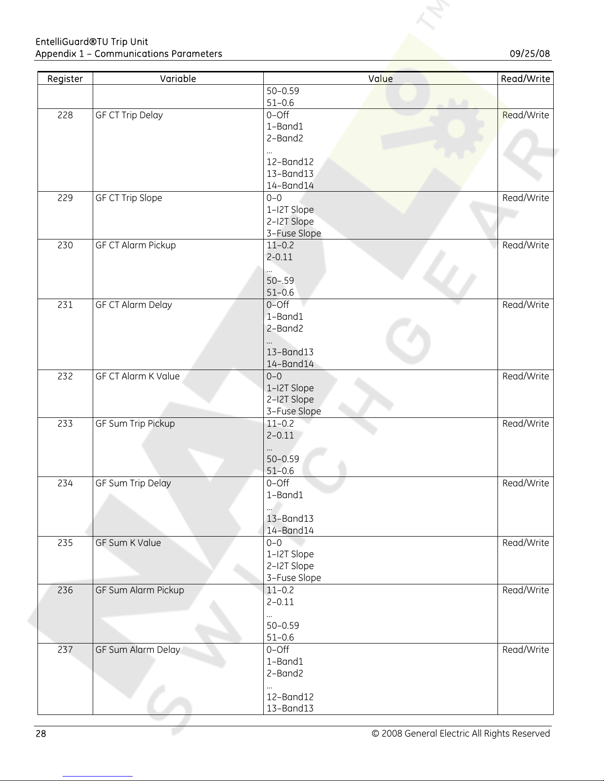
EntelliGuard®TU Trip Unit
Appendix 1 – Communications Parameters 09/25/08
Register Variable Value Read/Write
50–0.59
51–0.6
228 GF CT Trip Delay 0–Off
Read/Write
1–Band1
2–Band2
…
12–Band12
13–Band13
14–Band14
229 GF CT Trip Slope 0–0
Read/Write
1–I2T Slope
2–I2T Slope
3–Fuse Slope
230 GF CT Alarm Pickup 11–0.2
Read/Write
2-0.11
…
50–.59
51–0.6
231 GF CT Alarm Delay 0–Off
Read/Write
1–Band1
2–Band2
…
13–Band13
14–Band14
232 GF CT Alarm K Value 0–0
Read/Write
1–I2T Slope
2–I2T Slope
3–Fuse Slope
233 GF Sum Trip Pickup 11–0.2
Read/Write
2–0.11
…
50–0.59
51–0.6
234 GF Sum Trip Delay 0–Off
Read/Write
1–Band1
…
13–Band13
14–Band14
235 GF Sum K Value 0–0
Read/Write
1–I2T Slope
2–I2T Slope
3–Fuse Slope
236 GF Sum Alarm Pickup 11–0.2
Read/Write
2–0.11
…
50–0.59
51–0.6
237 GF Sum Alarm Delay 0–Off
Read/Write
1–Band1
2–Band2
…
12–Band12
13–Band13
28 © 2008 General Electric All Rights Reserved
Page 29
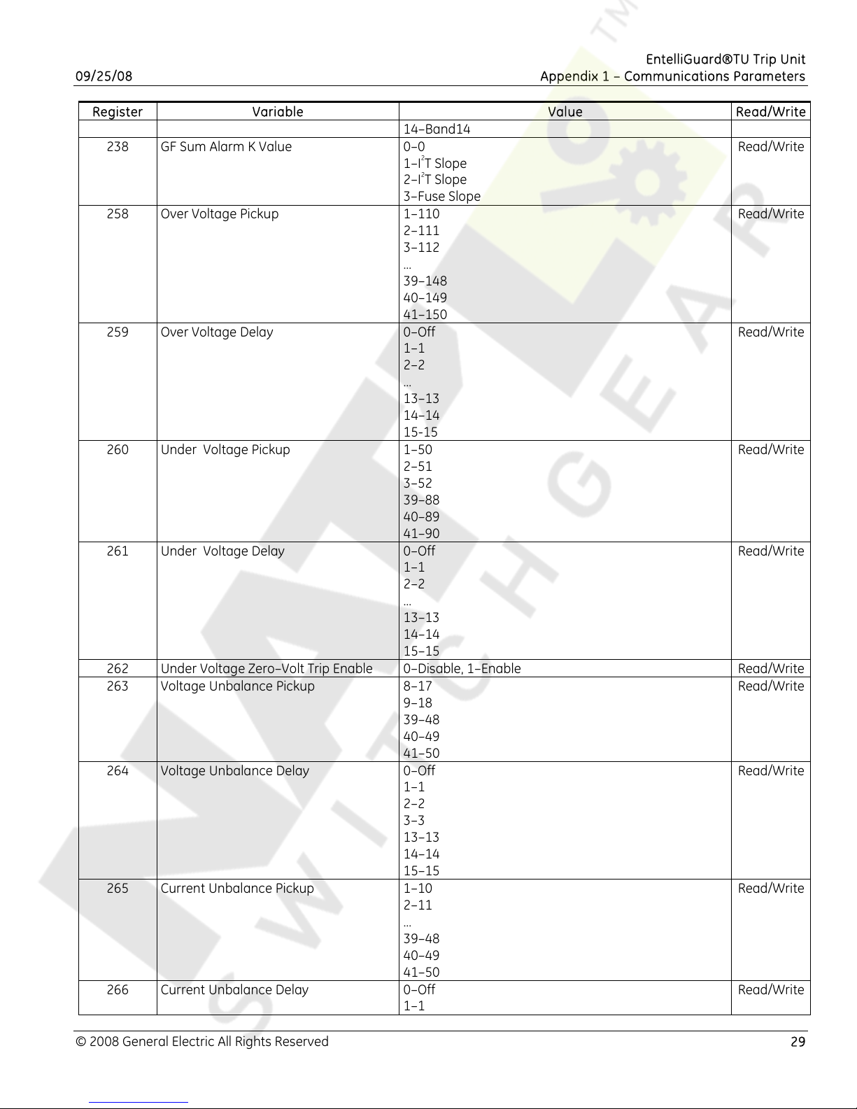
EntelliGuard®TU Trip Unit
09/25/08 Appendix 1 – Communications Parameters
Register Variable Value Read/Write
14–Band14
238 GF Sum Alarm K Value 0–0
Read/Write
1–I2T Slope
2–I2T Slope
3–Fuse Slope
258 Over Voltage Pickup 1–110
Read/Write
2–111
3–112
…
39–148
40–149
41–150
259 Over Voltage Delay 0–Off
Read/Write
1–1
2–2
…
13–13
14–14
15-15
260 Under Voltage Pickup 1–50
Read/Write
2–51
3–52
39–88
40–89
41–90
261 Under Voltage Delay 0–Off
Read/Write
1–1
2–2
…
13–13
14–14
15–15
262 Under Voltage Zero–Volt Trip Enable 0–Disable, 1–Enable Read/Write
263 Voltage Unbalance Pickup 8–17
Read/Write
9–18
39–48
40–49
41–50
264 Voltage Unbalance Delay 0–Off
Read/Write
1–1
2–2
3–3
13–13
14–14
15–15
265 Current Unbalance Pickup 1–10
Read/Write
2–11
…
39–48
40–49
41–50
266 Current Unbalance Delay 0–Off
Read/Write
1–1
© 2008 General Electric All Rights Reserved 29
Page 30
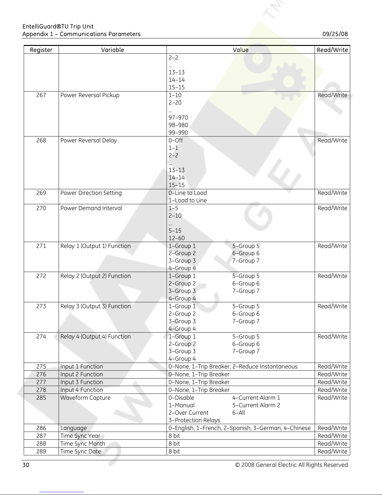
EntelliGuard®TU Trip Unit
Appendix 1 – Communications Parameters 09/25/08
Register Variable Value Read/Write
2–2
…
13–13
14–14
15–15
267 Power Reversal Pickup 1–10
Read/Write
2–20
…
97–970
98–980
99–990
268 Power Reversal Delay 0–Off
Read/Write
1–1
2–2
…
13–13
14–14
15–15
269 Power Direction Setting 0–Line to Load
Read/Write
1–Load to Line
270 Power Demand Interval 1–5
Read/Write
2–10
…
5–15
12–60
271 Relay 1 (Output 1) Function 1–Group 1
2–Group 2
3–Group 3
5–Group 5
6–Group 6
7–Group 7
Read/Write
4–Group 4
272 Relay 2 (Output 2) Function 1–Group 1
2–Group 2
3–Group 3
5–Group 5
6–Group 6
7–Group 7
Read/Write
4–Group 4
273 Relay 3 (Output 3) Function 1–Group 1
2–Group 2
3–Group 3
5–Group 5
6–Group 6
7–Group 7
Read/Write
4–Group 4
274 Relay 4 (Output 4) Function 1–Group 1
2–Group 2
3–Group 3
5–Group 5
6–Group 6
7–Group 7
Read/Write
4–Group 4
275 Input 1 Function 0–None, 1–Trip Breaker, 2–Reduce Instantaneous Read/Write
276 Input 2 Function 0–None, 1–Trip Breaker Read/Write
277 Input 3 Function 0–None, 1–Trip Breaker Read/Write
278 Input 4 Function 0–None, 1–Trip Breaker Read/Write
285 Waveform Capture 0–Disable
1–Manual
2–Over Current
4–Current Alarm 1
5–Current Alarm 2
6–All
Read/Write
3–Protection Relays
286 Language 0–English, 1–French, 2–Spanish, 3–German, 4–Chinese Read/Write
287 Time Sync Year 8 bit Read/Write
288 Time Sync Month 8 bit Read/Write
289 Time Sync Date 8 bit Read/Write
30 © 2008 General Electric All Rights Reserved
Page 31
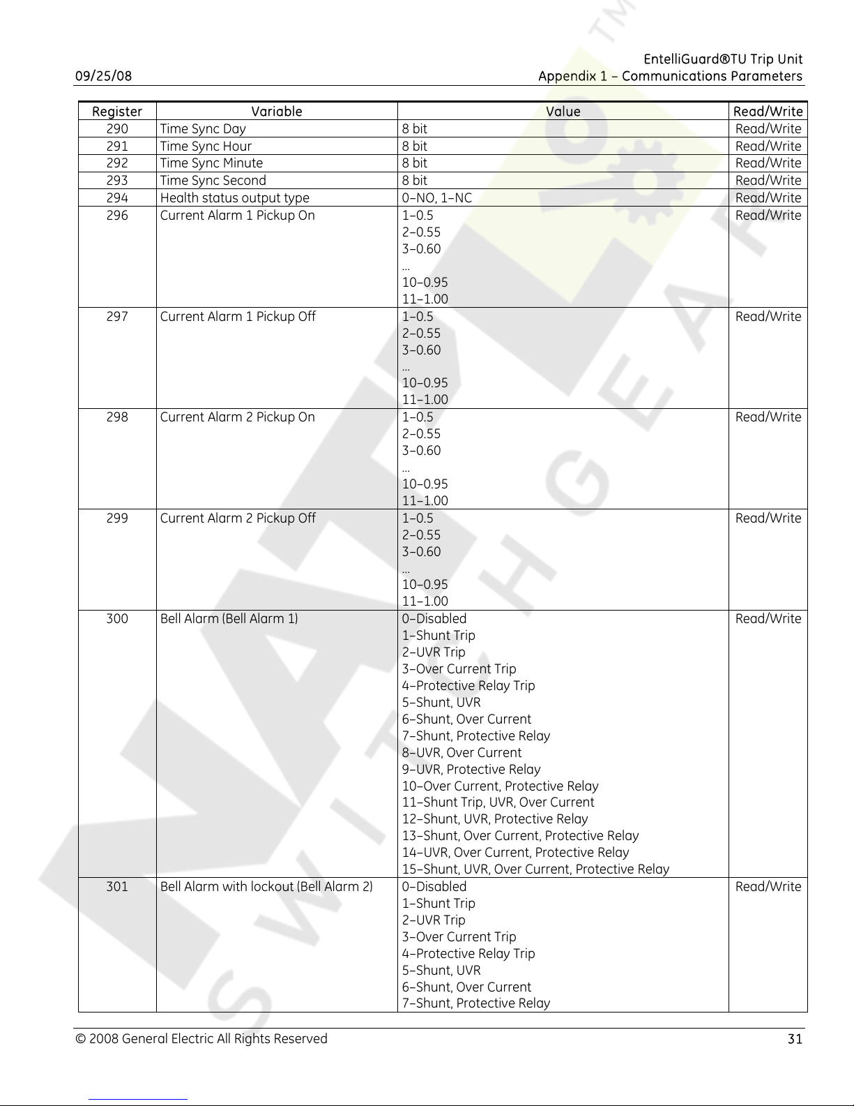
EntelliGuard®TU Trip Unit
09/25/08 Appendix 1 – Communications Parameters
Register Variable Value Read/Write
290 Time Sync Day 8 bit Read/Write
291 Time Sync Hour 8 bit Read/Write
292 Time Sync Minute 8 bit Read/Write
293 Time Sync Second 8 bit Read/Write
294 Health status output type 0–NO, 1–NC Read/Write
296 Current Alarm 1 Pickup On 1–0.5
Read/Write
2–0.55
3–0.60
…
10–0.95
11–1.00
297 Current Alarm 1 Pickup Off 1–0.5
Read/Write
2–0.55
3–0.60
…
10–0.95
11–1.00
298 Current Alarm 2 Pickup On 1–0.5
Read/Write
2–0.55
3–0.60
…
10–0.95
11–1.00
299 Current Alarm 2 Pickup Off 1–0.5
Read/Write
2–0.55
3–0.60
…
10–0.95
11–1.00
300 Bell Alarm (Bell Alarm 1) 0–Disabled
Read/Write
1–Shunt Trip
2–UVR Trip
3–Over Current Trip
4–Protective Relay Trip
5–Shunt, UVR
6–Shunt, Over Current
7–Shunt, Protective Relay
8–UVR, Over Current
9–UVR, Protective Relay
10–Over Current, Protective Relay
11–Shunt Trip, UVR, Over Current
12–Shunt, UVR, Protective Relay
13–Shunt, Over Current, Protective Relay
14–UVR, Over Current, Protective Relay
15–Shunt, UVR, Over Current, Protective Relay
301 Bell Alarm with lockout (Bell Alarm 2) 0–Disabled
Read/Write
1–Shunt Trip
2–UVR Trip
3–Over Current Trip
4–Protective Relay Trip
5–Shunt, UVR
6–Shunt, Over Current
7–Shunt, Protective Relay
© 2008 General Electric All Rights Reserved 31
Page 32
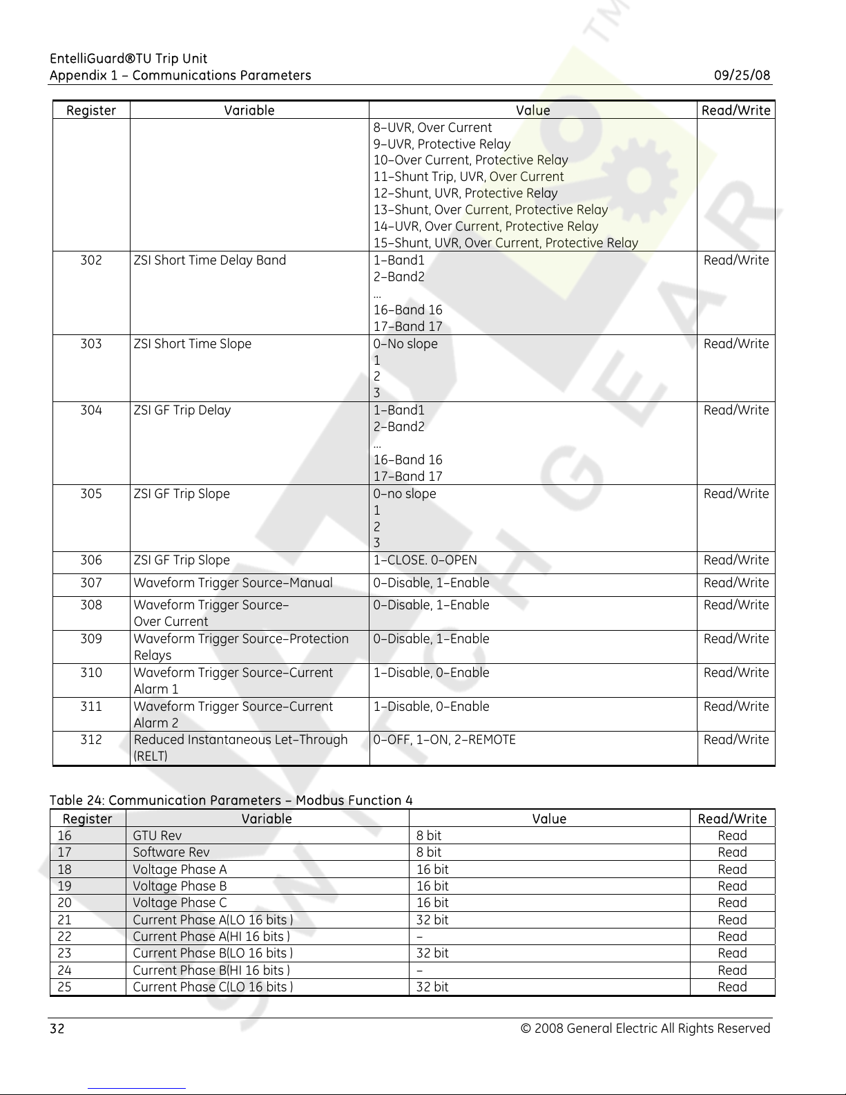
EntelliGuard®TU Trip Unit
Appendix 1 – Communications Parameters 09/25/08
Register Variable Value Read/Write
8–UVR, Over Current
9–UVR, Protective Relay
10–Over Current, Protective Relay
11–Shunt Trip, UVR, Over Current
12–Shunt, UVR, Protective Relay
13–Shunt, Over Current, Protective Relay
14–UVR, Over Current, Protective Relay
15–Shunt, UVR, Over Current, Protective Relay
302 ZSI Short Time Delay Band 1–Band1
Read/Write
2–Band2
…
16–Band 16
17–Band 17
303 ZSI Short Time Slope 0–No slope
Read/Write
1
2
3
304 ZSI GF Trip Delay 1–Band1
Read/Write
2–Band2
…
16–Band 16
17–Band 17
305 ZSI GF Trip Slope 0–no slope
Read/Write
1
2
3
306 ZSI GF Trip Slope 1–CLOSE. 0–OPEN Read/Write
307 Waveform Trigger Source–Manual 0–Disable, 1–Enable Read/Write
308 Waveform Trigger Source–
0–Disable, 1–Enable Read/Write
Over Current
309 Waveform Trigger Source–Protection
0–Disable, 1–Enable Read/Write
Relays
310 Waveform Trigger Source–Current
1–Disable, 0–Enable Read/Write
Alarm 1
311 Waveform Trigger Source–Current
1–Disable, 0–Enable Read/Write
Alarm 2
312 Reduced Instantaneous Let–Through
0–OFF, 1–ON, 2–REMOTE Read/Write
(RELT)
Table 24: Communication Parameters – Modbus Function 4
Register Variable Value Read/Write
16 GTU Rev 8 bit Read
17 Software Rev 8 bit Read
18 Voltage Phase A 16 bit Read
19 Voltage Phase B 16 bit Read
20 Voltage Phase C 16 bit Read
21 Current Phase A(LO 16 bits ) 32 bit Read
22 Current Phase A(HI 16 bits ) – Read
23 Current Phase B(LO 16 bits ) 32 bit Read
24 Current Phase B(HI 16 bits ) – Read
25 Current Phase C(LO 16 bits ) 32 bit Read
32 © 2008 General Electric All Rights Reserved
Page 33
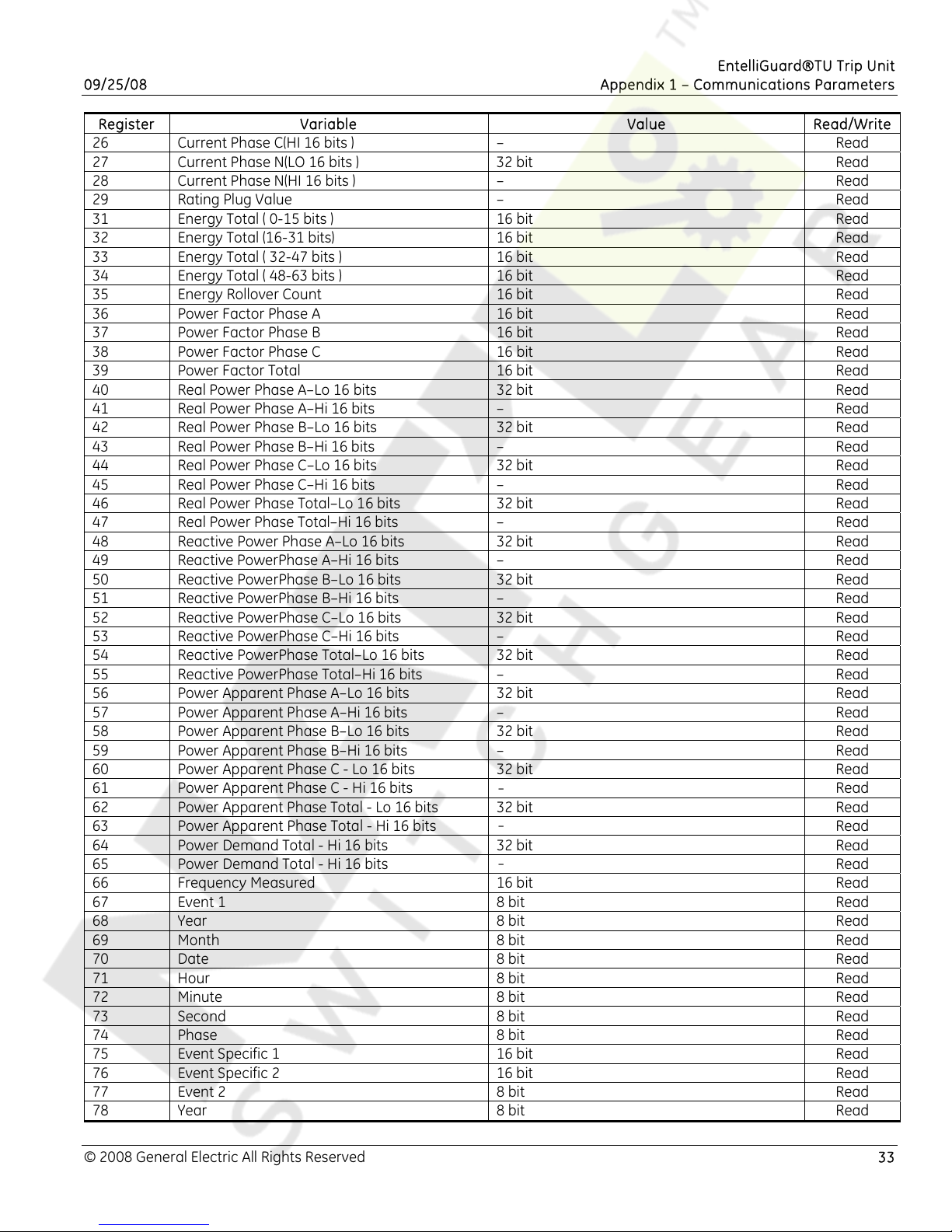
EntelliGuard®TU Trip Unit
09/25/08 Appendix 1 – Communications Parameters
Register Variable Value Read/Write
26 Current Phase C(HI 16 bits ) – Read
27 Current Phase N(LO 16 bits ) 32 bit Read
28 Current Phase N(HI 16 bits ) – Read
29 Rating Plug Value – Read
31 Energy Total ( 0-15 bits ) 16 bit Read
32 Energy Total (16-31 bits) 16 bit Read
33 Energy Total ( 32-47 bits ) 16 bit Read
34 Energy Total ( 48-63 bits ) 16 bit Read
35 Energy Rollover Count 16 bit Read
36 Power Factor Phase A 16 bit Read
37 Power Factor Phase B 16 bit Read
38 Power Factor Phase C 16 bit Read
39 Power Factor Total 16 bit Read
40 Real Power Phase A–Lo 16 bits 32 bit Read
41 Real Power Phase A–Hi 16 bits – Read
42 Real Power Phase B–Lo 16 bits 32 bit Read
43 Real Power Phase B–Hi 16 bits – Read
44 Real Power Phase C–Lo 16 bits 32 bit Read
45 Real Power Phase C–Hi 16 bits – Read
46 Real Power Phase Total–Lo 16 bits 32 bit Read
47 Real Power Phase Total–Hi 16 bits – Read
48 Reactive Power Phase A–Lo 16 bits 32 bit Read
49 Reactive PowerPhase A–Hi 16 bits – Read
50 Reactive PowerPhase B–Lo 16 bits 32 bit Read
51 Reactive PowerPhase B–Hi 16 bits – Read
52 Reactive PowerPhase C–Lo 16 bits 32 bit Read
53 Reactive PowerPhase C–Hi 16 bits – Read
54 Reactive PowerPhase Total–Lo 16 bits 32 bit Read
55 Reactive PowerPhase Total–Hi 16 bits – Read
56 Power Apparent Phase A–Lo 16 bits 32 bit Read
57 Power Apparent Phase A–Hi 16 bits – Read
58 Power Apparent Phase B–Lo 16 bits 32 bit Read
59 Power Apparent Phase B–Hi 16 bits – Read
60 Power Apparent Phase C - Lo 16 bits 32 bit Read
61 Power Apparent Phase C - Hi 16 bits
-
Read
62 Power Apparent Phase Total - Lo 16 bits 32 bit Read
63 Power Apparent Phase Total - Hi 16 bits
-
Read
64 Power Demand Total - Hi 16 bits 32 bit Read
65 Power Demand Total - Hi 16 bits
-
Read
66 Frequency Measured 16 bit Read
67 Event 1 8 bit Read
68 Year 8 bit Read
69 Month 8 bit Read
70 Date 8 bit Read
71 Hour 8 bit Read
72 Minute 8 bit Read
73 Second 8 bit Read
74 Phase 8 bit Read
75 Event Specific 1 16 bit Read
76 Event Specific 2 16 bit Read
77 Event 2 8 bit Read
78 Year 8 bit Read
© 2008 General Electric All Rights Reserved 33
Page 34
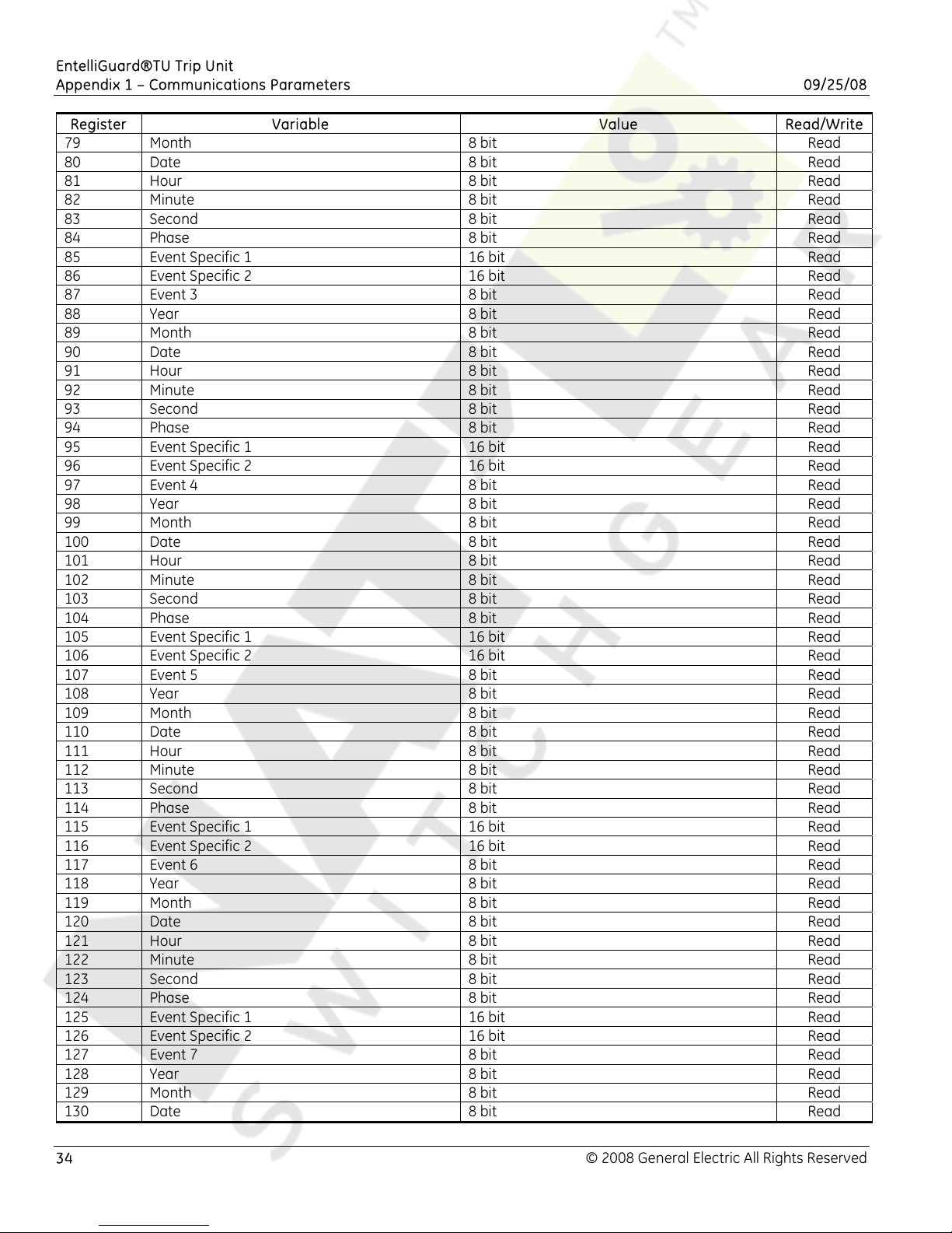
EntelliGuard®TU Trip Unit
Appendix 1 – Communications Parameters 09/25/08
Register Variable Value Read/Write
79 Month 8 bit Read
80 Date 8 bit Read
81 Hour 8 bit Read
82 Minute 8 bit Read
83 Second 8 bit Read
84 Phase 8 bit Read
85 Event Specific 1 16 bit Read
86 Event Specific 2 16 bit Read
87 Event 3 8 bit Read
88 Year 8 bit Read
89 Month 8 bit Read
90 Date 8 bit Read
91 Hour 8 bit Read
92 Minute 8 bit Read
93 Second 8 bit Read
94 Phase 8 bit Read
95 Event Specific 1 16 bit Read
96 Event Specific 2 16 bit Read
97 Event 4 8 bit Read
98 Year 8 bit Read
99 Month 8 bit Read
100 Date 8 bit Read
101 Hour 8 bit Read
102 Minute 8 bit Read
103 Second 8 bit Read
104 Phase 8 bit Read
105 Event Specific 1 16 bit Read
106 Event Specific 2 16 bit Read
107 Event 5 8 bit Read
108 Year 8 bit Read
109 Month 8 bit Read
110 Date 8 bit Read
111 Hour 8 bit Read
112 Minute 8 bit Read
113 Second 8 bit Read
114 Phase 8 bit Read
115 Event Specific 1 16 bit Read
116 Event Specific 2 16 bit Read
117 Event 6 8 bit Read
118 Year 8 bit Read
119 Month 8 bit Read
120 Date 8 bit Read
121 Hour 8 bit Read
122 Minute 8 bit Read
123 Second 8 bit Read
124 Phase 8 bit Read
125 Event Specific 1 16 bit Read
126 Event Specific 2 16 bit Read
127 Event 7 8 bit Read
128 Year 8 bit Read
129 Month 8 bit Read
130 Date 8 bit Read
34 © 2008 General Electric All Rights Reserved
Page 35
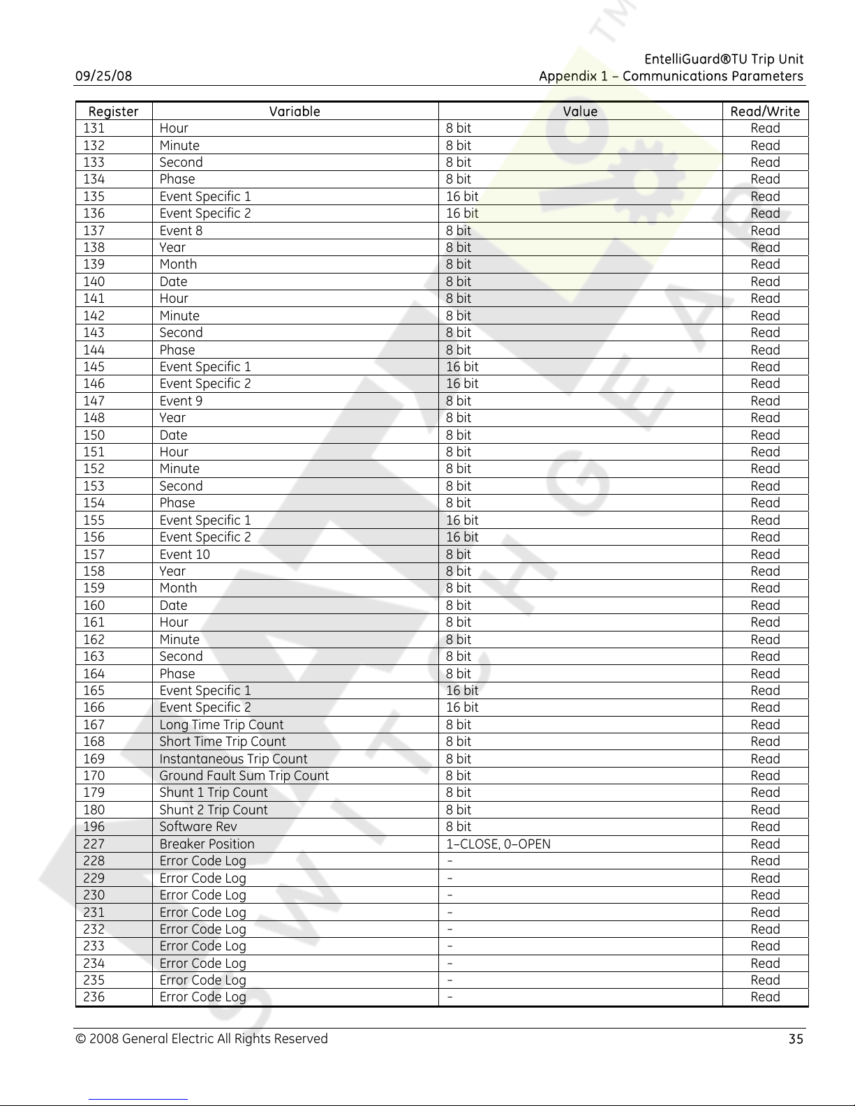
EntelliGuard®TU Trip Unit
09/25/08 Appendix 1 – Communications Parameters
Register Variable Value Read/Write
131 Hour 8 bit Read
132 Minute 8 bit Read
133 Second 8 bit Read
134 Phase 8 bit Read
135 Event Specific 1 16 bit Read
136 Event Specific 2 16 bit Read
137 Event 8 8 bit Read
138 Year 8 bit Read
139 Month 8 bit Read
140 Date 8 bit Read
141 Hour 8 bit Read
142 Minute 8 bit Read
143 Second 8 bit Read
144 Phase 8 bit Read
145 Event Specific 1 16 bit Read
146 Event Specific 2 16 bit Read
147 Event 9 8 bit Read
148 Year 8 bit Read
150 Date 8 bit Read
151 Hour 8 bit Read
152 Minute 8 bit Read
153 Second 8 bit Read
154 Phase 8 bit Read
155 Event Specific 1 16 bit Read
156 Event Specific 2 16 bit Read
157 Event 10 8 bit Read
158 Year 8 bit Read
159 Month 8 bit Read
160 Date 8 bit Read
161 Hour 8 bit Read
162 Minute 8 bit Read
163 Second 8 bit Read
164 Phase 8 bit Read
165 Event Specific 1 16 bit Read
166 Event Specific 2 16 bit Read
167 Long Time Trip Count 8 bit Read
168 Short Time Trip Count 8 bit Read
169 Instantaneous Trip Count 8 bit Read
170 Ground Fault Sum Trip Count 8 bit Read
179 Shunt 1 Trip Count 8 bit Read
180 Shunt 2 Trip Count 8 bit Read
196 Software Rev 8 bit Read
227 Breaker Position 1–CLOSE, 0–OPEN Read
228 Error Code Log
229 Error Code Log
230 Error Code Log
231 Error Code Log
232 Error Code Log
233 Error Code Log
234 Error Code Log
235 Error Code Log
236 Error Code Log
-
-
-
-
-
-
-
-
-
Read
Read
Read
Read
Read
Read
Read
Read
Read
© 2008 General Electric All Rights Reserved 35
Page 36
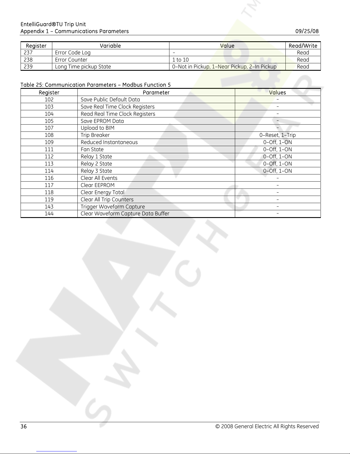
EntelliGuard®TU Trip Unit
Appendix 1 – Communications Parameters 09/25/08
Register Variable Value Read/Write
237 Error Code Log
-
Read
238 Error Counter 1 to 10 Read
239 Long Time pickup State 0–Not in Pickup, 1–Near Pickup, 2–In Pickup Read
Table 25: Communication Parameters – Modbus Function 5
Register Parameter Values
102 Save Public Default Data
103 Save Real Time Clock Registers
104 Read Real Time Clock Registers
105 Save EPROM Data
107 Upload to BIM
-
-
-
-
-
108 Trip Breaker 0–Reset, 1–Trip
109 Reduced Instantaneous 0–Off, 1–ON
111 Fan State 0–Off, 1–ON
112 Relay 1 State 0–Off, 1–ON
113 Relay 2 State 0–Off, 1–ON
114 Relay 3 State 0–Off, 1–ON
116 Clear All Events
117 Clear EEPROM
118 Clear Energy Total
119 Clear All Trip Counters
143 Trigger Waveform Capture
144 Clear Waveform Capture Data Buffer
-
-
-
-
-
-
36 © 2008 General Electric All Rights Reserved
Page 37
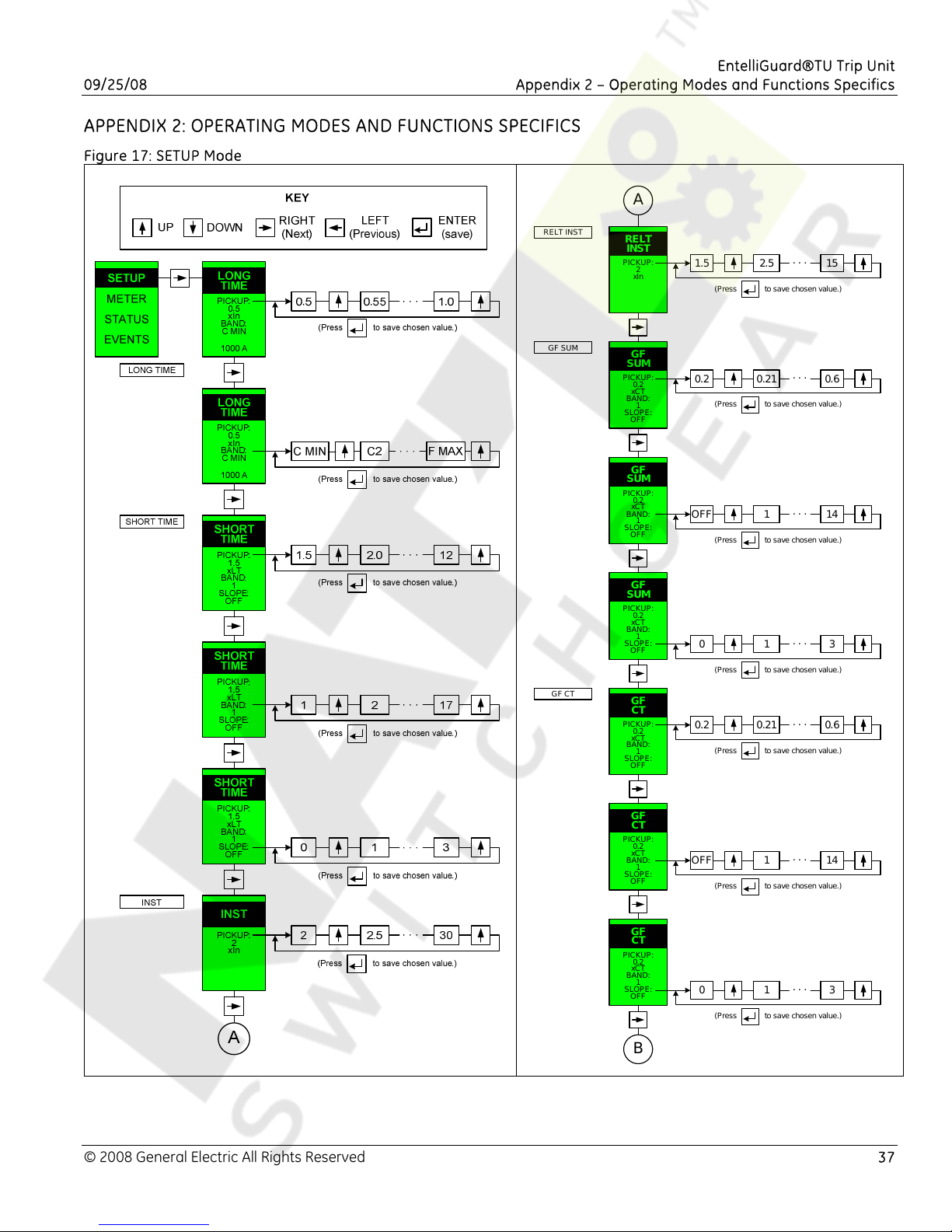
EntelliGuard®TU Trip Unit
09/25/08 Appendix 2 – Operating Modes and Functions Specifics
APPENDIX 2: OPERATING MODES AND FUNCTIONS SPECIFICS
Figure 17: SETUP Mode
A
RELT INST
GF SUM
GF CT
RELT
INST
PICKUP:
2
xIn
GF
SUM
PICKUP:
0.2
xCT
BAND:
1
SLOPE:
OFF
GF
SUM
PICKUP:
0.2
xCT
BAND:
1
SLOPE:
OFF
GF
SUM
PICKUP:
0.2
xCT
BAND:
1
SLOPE:
OFF
GF
CT
PICKUP:
0.2
xCT
BAND:
1
SLOPE:
OFF
1.5
0.2
OFF
0
0.2
2.5 15
(Press to save chosen value.)
0.21 0.6
(Press to save chosen value.)
1 14
(Press to save chosen value.)
1 3
(Press to save chosen value.)
0.21 0.6
(Press to save chosen value.)
. . .
. . .
. . .
. . .
. . .
© 2008 General Electric All Rights Reserved 37
GF
CT
PICKUP:
0.2
xCT
BAND:
1
SLOPE:
OFF
GF
CT
PICKUP:
0.2
xCT
BAND:
1
SLOPE:
OFF
B
OFF
(Press to save chosen value.)
0
(Press to save chosen value.)
1 14
1 3
. . .
. . .
Page 38
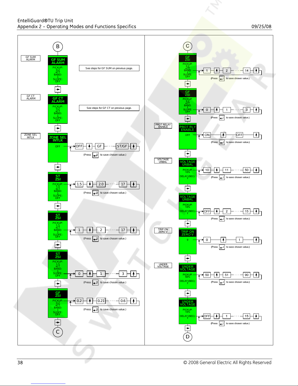
EntelliGuard®TU Trip Unit
Appendix 2 – Operating Modes and Functions Specifics 09/25/08
GF SUM
ALARM
GF CT
ALARM
ZONE SEL
INTLK
B
GF SUM
ALARM
PICKUP:
0.2
xCT
BAND:
1
SLOPE:
OFF
GF CT
ALARM
PICKUP:
0.2
xCT
BAND:
1
SLOPE:
OFF
ZONE SEL
INTLK
OFF
ST
ZSI
PICKUP:
1.5
xLT
BAND:
1
SLOPE:
OFF
See steps for GF SUM on prev ious page.
See steps for GF CT on previous page.
OFF
(Press to save chosen value.)
1.5
(Press to save chosen value.)
. . .
GF ST/GF
2.0 17
. . .
ST
ZSI
PICKUP:
1.5
xLT
BAND:
1
SLOPE:
OFF
ST
ZSI
PICKUP:
1.5
xLT
BAND:
1
SLOPE:
OFF
GF
ZSI
PICKUP:
0.2
xCT
BAND:
1
SLOPE:
OFF
1
(Press to save chosen value.)
0
(Press to save chosen value.)
0.2
(Press to save chosen value.)
. . .
2 17
. . .
1 3
. . .
0.21 0.6
C
38 © 2008 General Electric All Rights Reserved
Page 39
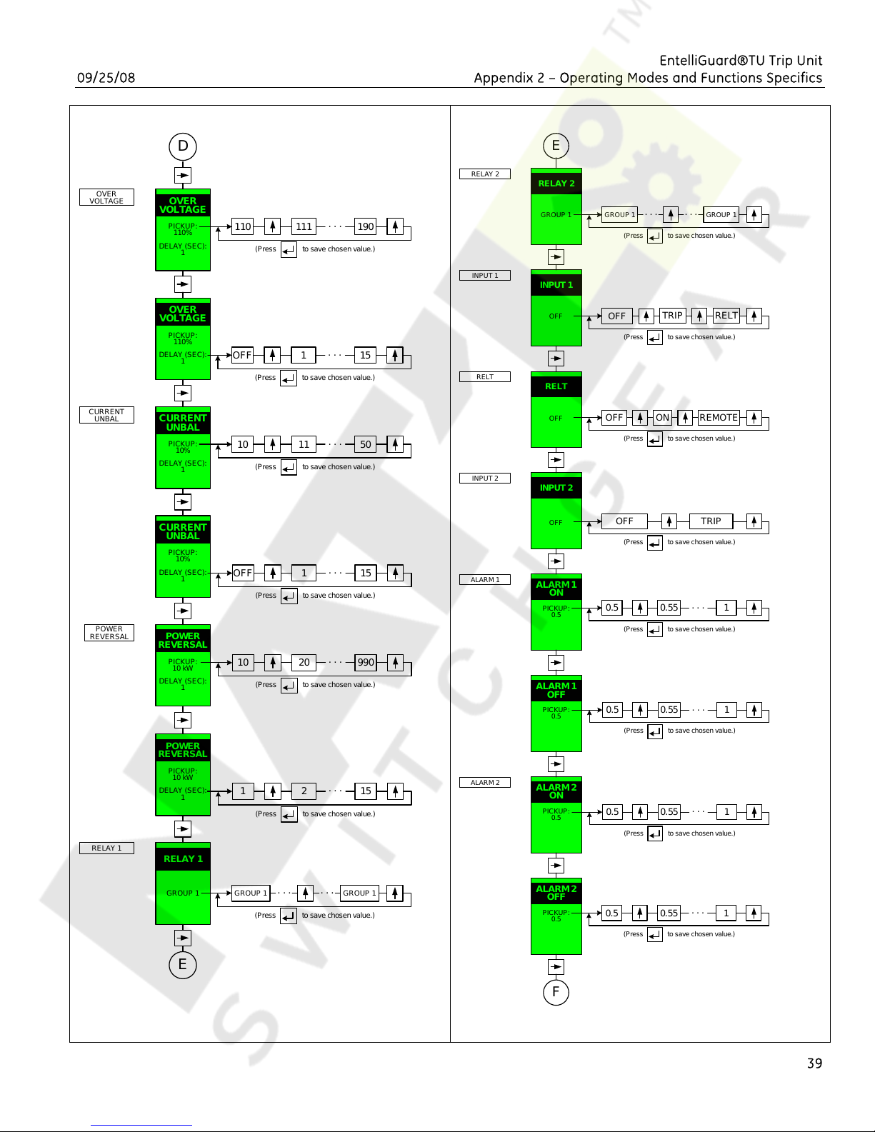
EntelliGuard®TU Trip Unit
09/25/08 Appendix 2 – Operating Modes and Functions Specifics
OVER
VOLTAGE
CURRENT
UNBAL
POWER
REVERSAL
RELAY 1
D
OVER
VOLTAGE
PICKUP:
110%
DELAY (SEC):
1
OVER
VOLTAGE
PICKUP:
110%
DELAY (SEC):
1
CURRENT
UNBAL
PICKUP:
10%
DELAY (SEC):
1
CURRENT
UNBAL
PICKUP:
10%
DELAY (SEC):
1
POWER
REVERSAL
PICKUP:
10 kW
DELAY (SEC):
1
POWER
REVERSAL
PICKUP:
10 kW
DELAY (SEC):
1
RELAY 1
110
OFF
10
OFF
10
1
111 190
(Press to save chosen value.)
1 15
(Press to save chosen value.)
11 50
(Press to save chosen value.)
1 15
(Press to save chosen value.)
20 990
(Press to save chosen value.)
2 15
(Press to save chosen value.)
. . .
. . .
. . .
. . .
. . .
. . .
RELAY 2
INPUT 1
RELT
INPUT 2
ALARM 1
ALARM 2
E
RELAY 2
GROUP 1
INPUT 1
OFF
RELT
OFF
INPUT 2
OFF
ALARM 1
ON
PICKUP:
0.5
ALARM 1
OFF
PICKUP:
0.5
ALARM 2
ON
PICKUP:
0.5
. . .
GROUP 1
(Press to save chosen value.)
OFF
(Press to save chosen value.)
OFF
(Press to save chosen value.)
. . .
TRIP
ON
OFF TRIP
(Press to save chosen value.)
0.5
0.5
0.5
0.55 1
(Press to save chosen value.)
0.55 1
(Press to save chosen value.)
0.55 1
(Press to save chosen value.)
GROUP 1
RELT
REMOTE
. . .
. . .
. . .
GROUP 1
. . .
GROUP 1
(Press to save chosen value.)
E
39
. . .
GROUP 1
ALARM 2
OFF
PICKUP:
0.5
0.5
(Press to save chosen value.)
. . .
0.55 1
F
Page 40
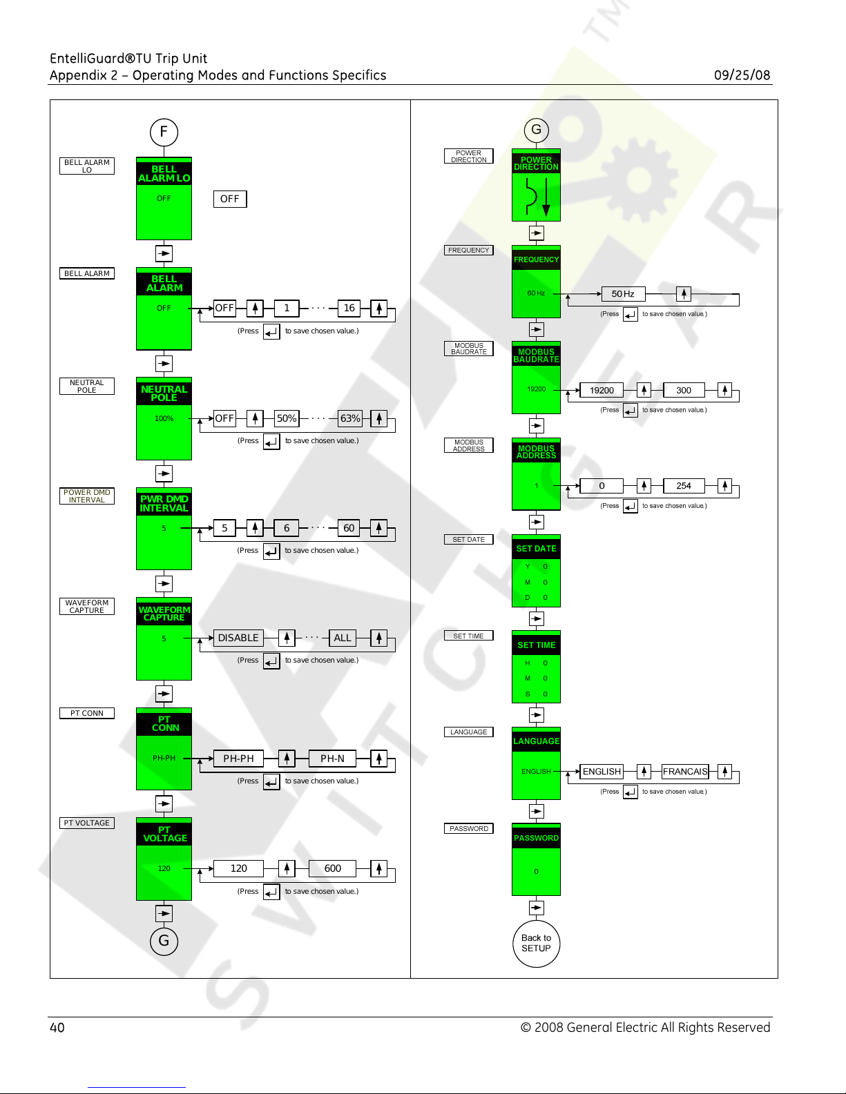
EntelliGuard®TU Trip Unit
Appendix 2 – Operating Modes and Functions Specifics 09/25/08
BELL ALARM
LO
BELL ALARM
NEUTRAL
POLE
POWER DMD
INTERVAL
F
BELL
ALARM LO
OFF
BELL
ALARM
OFF
NEUTRAL
POLE
100%
PWR DMD
INTERVAL
5
OFF
OFF
(Press to save chosen value.)
OFF
(Press to save chosen value.)
5
(Press to save chosen value.)
1 16
50% 63%
6 60
. . .
. . .
. . .
WAVEFORM
CAPTURE
PT CONN
PT VOLTAGE
WAVEFORM
CAPTURE
5
PT
CONN
PH-PH
PT
VOLTAGE
120
G
DISABLE ALL
(Press to save chosen value.)
. . .
PH-PH PH-N
(Press to save chosen value.)
120 600
(Press to save chosen value.)
40 © 2008 General Electric All Rights Reserved
Page 41
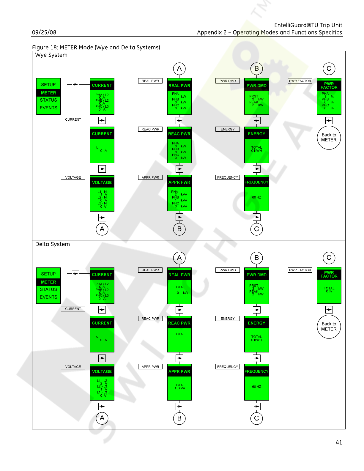
EntelliGuard®TU Trip Unit
09/25/08 Appendix 2 – Operating Modes and Functions Specifics
Figure 18: METER Mode (Wye and Delta Systems)
Wye System
Delta System
41
Page 42
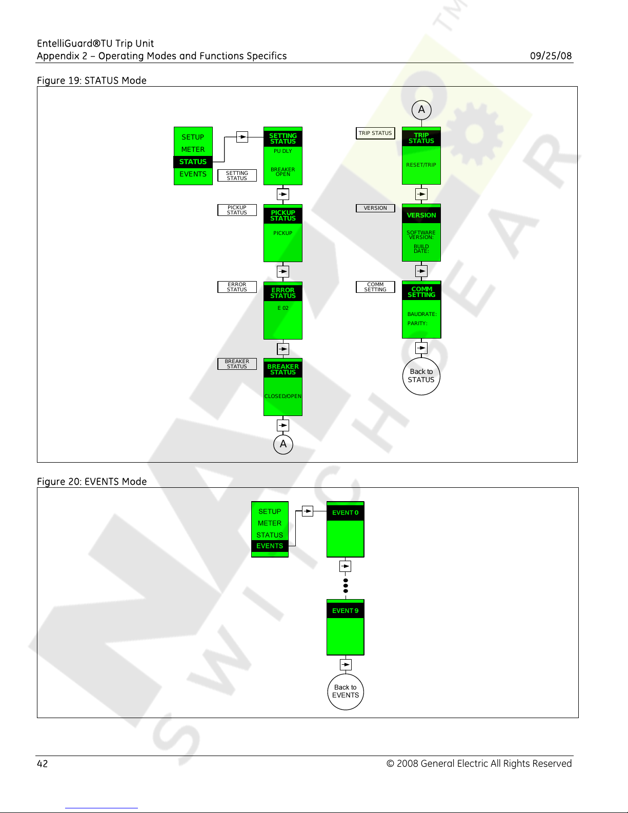
EntelliGuard®TU Trip Unit
Appendix 2 – Operating Modes and Functions Specifics 09/25/08
Figure 19: STATUS Mode
A
SETUP
METER
STATUS
STATUS
EVENTS
SETTING
STATUS
PICKUP
STATUS
ERROR
STATUS
BREAKER
STATUS
SETTING
STATUS
PU DLY
BREAKER
OPEN
PICKUP
STATUS
PICKUP
ERROR
STATUS
E 02
BREAKER
STATUS
CLOSED/OPEN
TRIP STATUS
VERSION
COMM
SETTING
TRIP
STATUS
RESET/TRIP
VERSION
SOFTWARE
VERSION:
BUILD
DATE:
COMM
SETTING
BAUDRATE:
PARITY:
Back to
STATUS
Figure 20: EVENTS Mode
A
42 © 2008 General Electric All Rights Reserved
Page 43

EntelliGuard®TU Trip Unit
09/25/08 Appendix 2 – Operating Modes and Functions Specifics
43
Page 44
EntelliGuard®TU Trip Unit
Appendix 2 – Operating Modes and Functions Specifics 09/25/08
EntelliGuard, WavePro and Power Break are registered trademarks of the General Electric Company.
GE
41 Woodford Avenue
Plainville, CT 06062
www.geelectrical.com
DEH-4567 Rev 01.
© 2008 General Electric All Rights Reserved
 Loading...