

Page 1

GFK-2993F
Field
User
July 2017
Agents*
Guide
For public
disclosure
Page 2
GFK-2993F 2
For public disclosure
These instructions do not purport to cover all details or variations in equipment, nor to provide for every
Location
Description
Removed this section — this content has been moved to Mini Field Agent (MFA)
Removed this section — this content has been moved to Field Agents Secure
Power Requirements
Corrected the operating temperature range
Configure a Network Proxy
Removed instructions for Bypass Proxy Server and Test Connection
Create a Device Representation in
Assign the Technician to the Field Agent
Obtain Enrollment Information
Throughout Document
Revision C: Added Embedded Field Agent (EFA)
Throughout Document
Revision D: Added Virtual Field Agent (VFA)
Throughout Document
Revision E: Added cellular, Wi-Fi hotspot, and Predix Machine 17.1
Throughout Document
Revision F: Improved documentation for time synchronization, system time, and
contingency
to be met during installation, operation, and maintenance. The information is supplied for informational
possible
purposes only, and GE makes no warranty as to the accuracy of the information included herein. Changes,
modifications, and/or improvements to equipment and specifications are made periodically and these changes may or
may not be reflected herein. It is understood that GE may make changes, modifications, or improvements to the
equipment referenced herein or to the document itself at any time. This document is intended for trained personnel
familiar with the GE products referenced herein.
GE may have patents or pending patent applications covering subject matter in this document. The furnishing
of this document does not provide any license whatsoever to any of these patents.
Public – This document is approved for public disclosure.
GE provides the following document and the information included therein as is and without warranty of
any kind, expressed or implied, including but not limited to any implied statutory warranty of
merchantability or fitness for particular purpose.
For further assistance or technical information, contact the nearest GE Sales or Service Office, or an authorized GE
Sales
Representative.
Revised: June 2017
Issued: Aug 2016
© 2016 – 2017 General Electric Company.
* Indicates a trademark of General Electric Company and/or its
subsidiaries. All other trademarks are the property of their respective
owners.
We would appreciate your feedback about our
documentation. Please send comments or suggestions
to controls.doc@ge.com
Document Updates
MFA Important Product Information
Secure Deployment
EdgeManager
Important Product Information (GFK-2997)
Deployment Guide (GFK-3009)
Replaced multiple screenshots to reflect Predix* EdgeManager* screen updates,
specifically the dashboard option Control Panel and related windows were
replaced with Settings
enhancements for Mini Field Agent (MFA)
Configuration and Application Management and ope ning ports.
Page 3
GFK-2993F 3
For public disclosure
Safety Symbol Legend
Warning
Caution
Attention
Indicates a procedure or condition that, if not strictly observed, could result in
personal injury or death.
Indicates a procedure or condition that, if not strictly observed, could result in damage
to or destruction of equipment.
Indicates a procedure or condition that should be strictly followed to improve these
applications.
Page 4
GFK-2993F 4
For public disclosure
If you purchased this product through an Authorized Channel Partner, please contact the seller directly.
General Contact Information
Online technical support https://ge-ip.force.com/communities/CC_Contact
Additional information http://www.geautomation.com/contact-us
Solution Provider http://www.geautomation.com/solution-partners
Technical Support
If you have technical problems that cannot be resolved with the information in this manual, please contact us by
telephone or on the web at https://ge-ip.force.com/communities/CC_Contact
Americas
Online Technical Support https://ge-ip.force.com/communities/CC_Contact
Phone 1-800-433-2682
International Americas Direct Dial 1-780-420-2010 (if toll free 800 option is unavailable)
Technical Support Email support.ip@ge.com
Customer Care Email customercare.ip@ge.com
Primary language of support English
Europe, the Middle East, and Africa
Online Technical Support https://ge-ip.force.com/communities/CC_Contact
Phone
EMEA Direct Dial
+
800-1-433-2682
+
420-23-901-5850 (if toll free 800 option is unavailable or
dialing from a mobile telephone)
Technical Support Email support.emea.ip@ge.com
Customer Care Email customercare.emea.ip@ge.com
Primary languages of support English, Fr ench, German, Italian, Czech, Spanish
Asia Pacific
Online Technical Support https://ge-ip.force.com/communities/CC_Contact
Phone
+
86-400-820-8208
+
86-21-3217-4826 (India, Indonesia, and Pakistan)
Technical Support Email support.cn.ip@ge.com (China)
support.jp.ip@ge.com (Japan)
support.in.ip@ge.com (remaining As ia customers)
Customer Care Email customercare.apo.ip@ge.com
customercare.cn.ip@ge.com (China)
Page 5

GFK-2993F 5
For public disclosure
Contents
1 Overview ............................................................................................................................................ 8
1.1 Applicable Products ...................................................................................................................... 8
1.2 Related Documentation ................................................................................................................ 9
1.3 Field Agent Architecture ............................................................................................................. 10
1.4 Mini Field Agent (MFA) ............................................................................................................... 11
1.4.1 MFA Specifications ................................................................................................................................................ 12
1.5 Embedded Field Agent (EFA) ..................................................................................................... 14
1.5.1 Mark* VIe IS420UCSCH1A CPU w/ Field Agent ................................................................................................ 14
1.5.2 PACSystems IC6 95CPE400 RX3i Rackless CPU w/ Field Agent ........................................................................ 14
1.6 Virtual Field Agent (VFA) ............................................................................................................ 15
2 MFA Hardware Instructions ............................................................................................................ 16
2.1 Internal Components .................................................................................................................. 16
2.1.1 Installation .............................................................................................................................................................. 17
2.1.1.1 DIN Rail Mount.................................................................................................................................................. 18
2.1.1.2 Panel Mount ....................................................................................................................................................... 19
2.1.1.3 MFA Interface Details ........................................................................................................................................ 20
2.1.1.4 Power Requi rements ........................................................................................................................................... 21
2.1.1.5 Pin Definitions .................................................................................................................................................... 22
2.1.1.6 Network Configuration ....................................................................................................................................... 22
2.1.2 Push Button and LEDs ........................................................................................................................................... 23
2.2 Push Button Operations .............................................................................................................. 24
2.2.1 Configuration Mode ............................................................................................................................................... 24
2.2.2 Reboot .................................................................................................................................................................... 25
2.2.3 Factory Reset .......................................................................................................................................................... 25
2.3 Field Agent Sales Catalog .......................................................................................................... 26
2.3.1 GE MFA Orderable Items ...................................................................................................................................... 26
2.3.2 MFA Included Items .............................................................................................................................................. 26
2.3.3 MFA Accessories ................................................................................................................................................... 26
2.4 Agency Certifications and Standards .......................................................................................... 27
2.4.1 Federal Commu nications Commission ( FCC)........................................................................................................ 28
2.5 Replacement and Spares ........................................................................................................... 29
2.5.1 Replacement Procedure .......................................................................................................................................... 29
2.5.2 Renewals and Spares .............................................................................................................................................. 30
3 EFA Hardware Instructions ............................................................................................................ 32
3.1 Mark* VIe IS420UCSCH1A CPU w/ Field Agent ......................................................................... 32
3.1.1 UCSC EFA – Network Configurat ion .................................................................................................................... 32
3.1.2 UCSC EFA – Push Button and LED ...................................................................................................................... 33
3.2 PACSystems IC695CPE400 RX3i Rackless CPU w/ Field Agent ............................................... 34
3.2.1 CPE400 EFA -- Network Configuration ................................................................................................................ 34
3.2.2 CPE400 EFA – LED, Display, and Push Buttons .................................................................................................. 35
3.3 GE EFA Orderable Items ............................................................................................................ 36
4 VFA Instructions ............................................................................................................................. 37
4.1 Network Configuration ................................................................................................................ 37
4.2 Configuration Mode .................................................................................................................... 37
4.3 Virtual Machine Deployment ....................................................................................................... 37
4.4 Virtual Machine Snapshots .........................................................................................................
4.5 GE VFA Orderable Items ............................................................................................................ 37
5 Getting Started with the Field Agent ............................................................................................. 38
5.1 What’s the Minimum I Need to Do to Get Going? ....................................................................... 38
5.2 Register the Field Agent ............................................................................................................. 38
5.3 Collect Enrollment and Configuration Information ....................................................................... 39
5.4 Start the Field Agent ................................................................................................................... 39
5.5 Log into the Web Console .......................................................................................................... 40
5.6 Configure the Network ................................................................................................................ 42
37
Page 6

GFK-2993F 6
For public disclosure
5.6.1 IP Addresses ........................................................................................................................................................... 42
5.6.1.1 To Identify/Change an IP Address ..................................................................................................................... 42
5.6.2 Configure a Network Proxy.................................................................................................................................... 44
5.6.3 Configure the Cellular Network ............................................................................................................................. 45
5.6.3.1 Enabling the Cellular Modem ............................................................................................................................ 45
5.6.3.2 Configure the Access Point Name ...................................................................................................................... 46
5.6.3.3 View the Cellular Status ..................................................................................................................................... 46
5.6.3.4 Cellular Plan and SIM Diagnostics .................................................................................................................... 46
5.7 Configure Time Synchronization ................................................................................................. 47
5.7.1 Using NTP Time Synchroniza tion ......................................................................................................................... 47
5.7.2 Using HTTPS Time Synchronization ..................................................................................................................... 48
5.8 Update the Field Agent ............................................................................................................... 49
5.8.1 Access the Field Agent Updater ............................................................................................................................. 49
To access the Field Agent Updater ..................................................................................................................................... 49
5.8.2 Method 1: Manual Local Update Using a Local Area Network ............................................................................. 51
To manually initiate a local upd ate using a Local Area Network connection .................................................................... 51
5.8.3 Method 2: Manual Cloud Update over the Internet ................................................................................................ 52
To manually initiate a cloud update over the Internet ........................................................................................................ 52
5.8.4 Method 3: Automatic Cloud Update over the Internet ........................................................................................... 53
To configure automatic cloud updates over the Internet .................................................................................................... 53
5.8.5 Upgrade Predix Machine If Applicable .................................................................................................................. 54
5.9 Configure EdgeManager Access ................................................................................................ 55
5.9.1 Create Accounts for Operator and Technician Roles ............................................................................................. 55
5.10 Enroll Field Agent in Predix Cloud ........................................................................................... 56
5.10.1 Enroll using EdgeManager ..................................................................................................................................... 56
5.10.1.1 Create a Device Representation in EdgeManager .......................................................................................... 57
5.10.1.2 Obtain Enrollment Informatio n ...................................................................................................................... 58
5.10.1.3 Log into Predix Cloud Enrollment Page in Field Agent Web Console .......................................................... 59
5.10.1.4 Enter Enrollment Information and Trigger Enrollment .................................................................................. 59
5.10.1.4.1 Using Certificate Enrollment ..................................................................................................................... 60
5.10.1.4.2 Using OAut h Authentication Code Enrollment ......................................................................................... 62
5.10.1.5 Verify the Field Agent is Online in EdgeManager ......................................................................................... 63
5.10.2 Enrolling Mini Field Agent Using iPhone App ...................................................................................................... 64
6 Using the Field Agent ..................................................................................................................... 66
6.1 Device Management ................................................................................................................... 66
6.1.1 Field Agent Status .................................................................................................................................................. 66
6.1.1.1 Using Edge Manager - Field Agent Health Status and Resource Usage ............................................................ 66
6.1.1.2 Using Web Console – Status Information .......................................................................................................... 66
6.1.2 Field Agent Co mmands .......................................................................................................................................... 68
6.1.2.1 Using Edge Manager - Supported Field Agent Commands................................................................................ 68
6.1.2.2 Using Web Console – Sending Commands ........................................................................................................ 69
6.1.2.3 When might a Factory Reset be required ........................................................................................................... 69
6.1.3 Configurati on Management .................................................................................................................................... 70
6.1.3.1 EdgeManager Configuration Management......................................................................................................... 70
6.1.3.2 Compression Utilities ......................................................................................................................................... 71
6.1.3.3 Predix Machine Web Console Configuration Management ............................................................................... 72
6.1.4 Application Management ....................................................................................................................................... 74
6.1.4.1 EdgeManager Application Management ............................................................................................................ 74
6.1.4.2 Predix Machine Web Console Application Management ................................................................................... 74
6.1.5 How to Open Ports on a Field Agent ...................................................................................................................... 76
6.1.5.1 The Ports Configuration File .............................................................................................................................. 76
6.1.5.2 Activating the Ports Configuratio n ..................................................................................................................... 76
6.2 Configuring Data Collection and Sending Data to the Cloud ....................................................... 77
6.2.1 Determine the Data Source and Data to Consume ................................................................................................. 77
6.2.2 Field Agent C onfiguration Tool ............................................................................................................................. 77
6.2.3 Configure the Field Agent Data Source ................................................................................................................. 77
6.2.3.1 Configure an OPC UA Data Source ................................................................................................................... 78
6.2.3.2 Configure a Modbus TCP Data Source .............................................................................................................. 79
6.2.4 Configure Sending Data to the Predix Cloud ......................................................................................................... 80
6.2.5 Guidelines for Maximum Configured Variables .................................................................................................... 81
6.2.5.1 Using the OPC UA Machine Adapter without Store and Forward ..................................................................... 81
Page 7

GFK-2993F 7
For public disclosure
6.2.5.2 Using Store and Forward with the OPC UA Machine Adapter .......................................................................... 82
6.2.5.3 Using the Modbus TCP Machine Adapter.......................................................................................................... 83
6.2.5.4 Using Store and Forward When Internet Connectivity is Disrupted and Restored ............................................ 84
6.2.6 Reconfigure the Field Agent .................................................................................................................................. 85
6.2.6.1 First Time Configuration .................................................................................................................................... 85
6.2.6.2 Reconfiguration for Production Environment .................................................................................................... 85
Page 8

1 Overview
1.1 Applicable Products
Product Family
Catalog
Number
Description Provisioning Connection Data Source
Connection
Cloud Connection
Mini Field Agent (MFA)
ICMFA000000 Field Agent as a standalone appliance for
connecting to external data sources.
• Ethernet LAN • Ethernet LAN • Ethernet WAN
ICMFA002US0
ICMFA002EU0
Field Agent as a standalone appliance for
connecting to external data sources.
Includes optional Wi-Fi hotspot for
provisioning.
• Ethernet LAN
• Wi-Fi hotspot with U.S./Canada
or European country code and
frequencies per catalog number
• Ethernet LAN • Ethernet WAN
ICMFA001US1
ICMFA001EU1
Field Agent as a standalone appliance for
connecting to external data sources.
Includes optional Wi-Fi hotspot for
provisioning and optional private cellular
cloud connection on AT&T®.
• Ethernet LAN
• Wi-Fi hotspot with U.S./Canada
or European country code and
frequencies per catalog number
• Ethernet LAN • Ethernet WAN
• AT&T private cellular
network in the
U.S./Canada or
European Union per
catalog number
ICMFA001US0
ICMFA001EU0
Field Agent as a standalone appliance for
connecting to external data sources.
Includes optional Wi-Fi hotspot for
provisioning and optional cellular cloud
connection on customer-
provided network.
• Ethernet LAN
• Wi-Fi hotspot with U.S./Canada
or European country code and
frequencies per catalog number
• Ethernet LAN • Ethernet WAN
• Cellular network in the
U.S./Canada or
European Union per
catalog number using
customer-provided SIM
Embedded Field Agent (EFA)
IC695CPE400 Field Agent embedded in an Industrial
Internet Control System running
PACSystems*.
• Ethernet WAN in Configuration
Mode only
•
Virtual LAN through
hypervisor
• Ethernet WAN
• Ethernet WAN
IS4200UCSCH1A Field Agent embedded in an Industrial
Internet Control System running Mark*
VIe.
• Ethernet WAN in Configuration
Mode only
•
Virtual LAN through
hypervisor
• Ethernet WAN
• Ethernet WAN
Virtual Field Agent (VFA)
117T6408Gxxxx Field Agent as a virtual machine image in
a Control Server.
• Virtual LAN1 through hypervisor
• Virtual LAN2 through hypervisor
• Virtual LAN1
through hypervisor
• Virtual LAN2
through hypervisor
• Virtual WAN through
hypervisor
Page 9

GFK-2993F 9
For public disclosure
1.2 Related Documentation
Product
URL
Mini Field Agent
https://digitalsupport.ge.com/communities/en_US/Article/ICMFA000000-Landing-Page
CPE400 with
Agent
https://digitalsupport.ge.com/communities/en_US/Article/IC695CPE400-Landing-Page
Virtual Field Agent
https://digitalsupport.ge.com/communities/en_US/Article/ICVFA000000-Landing-Page
Document ID
Document Title
GFK-3009
Field Agents Secure Deployment Guide
GFK-3017
Mini Field Agent Upgrade Guide
GFK-3018
Field Agents Registration Guide
GFK-3019
Field Agent Machine Adapters User Guide
GFK-2830
PACSystems* RXi, RX3i, and RX7i Controllers Secure Deployment Guide
GFK-2222
PACSystems CPU Reference Manual
GFK-2314
PACSystems RX3i System Manual
GFK-2224
TCP/IP Ethernet Communications for PACSystems User’s Manual
GFK-2225
TCP/IP Ethernet Communications for PACSystems Station Manager Manual
GFK-2571
PACSystems RX3i PROFINET Controller Manual
GFK-2572
PACSystems RX3i PROFINET Controller Command Li ne Interface Manual
GFK-2904
PROFINET IO Devices Secure Deployment Guide
GEH-6721 Vol I
Mark* VIe and Mark* VIeS Control Systems Volume I: System Guide
GEH-6721 Vol II
Mark* VIe and Mark* VIeS Control Systems Volume II: General-purpose Applications
GEH-6721 Vol III
Mark* VIe and Mark* VIeS Control Systems Volume III: For GE Industrial Applications
GEH-6839
Mark* VIe Control Systems Secure Deployment Guide
GEH-6700
ToolboxST* User Guide for Mark* Controls Platform
GEH-6767
Security Baseline Information for Mark* VIe Control
GEA-S1289
Cyber Security Management System for Mark* VIe Control
GFA-2120B
Mark* VIe UCSC Outcome Optimizing Control for Power Generation Applications
GEH-6851
Control Server – High Availability (HA) Maintenance Guide
Product Landing Pages
Embedded Field
Other Documentation
Page 10
GFK-2993F 10
For public disclosure
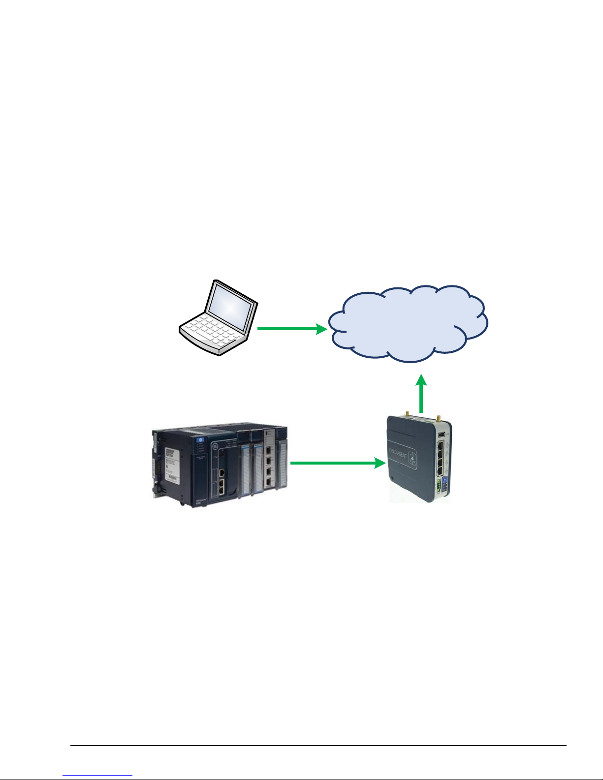
1.3 Field Agent Architecture
The goal of Field Agent technology is to connect industrial machines to the Predix* Cloud, so that asset owners can receive
insights and optimization for their equipment. Field Agents connect and transmit this data securely. Operators can then
visualize the performance of their assets and enable predictive analytics. Armed with this valuable information, operators can
optimize equipment uptime. OEMs can proactively maintain and service their equipment fleet, improving operations, growing
service revenues and winning new business. Asset owners can evolve past a break-fix model and implement predictive
analytics to minimize unplanned downtime.
GE has developed a family of Field Agent devices to address the challenges of communicating equipment data. A Field
Agent has two primary functions:
• Collecting and transmitting machine data securely
• A platform for running applications at the edge
Once a Field Agent is up and running, data is transferred from the plant to the cloud over encrypted channels, preserving its
time stamp, quality, and fidelity. It also provides a rich domain application environment for edge processing, so logic can be
executed at the most appropriate place in the architecture — locally on the machine or in the cloud.
HTTPS
Using
Device
Customer Access
Laptop or Mobile
Control System at Customer Site Field Agent at Customer Site
OPC
Modbus
TCP,
UA,
etc.
Predix Cloud
HTTPS
Page 11
GFK-2993F 11
For public disclosure
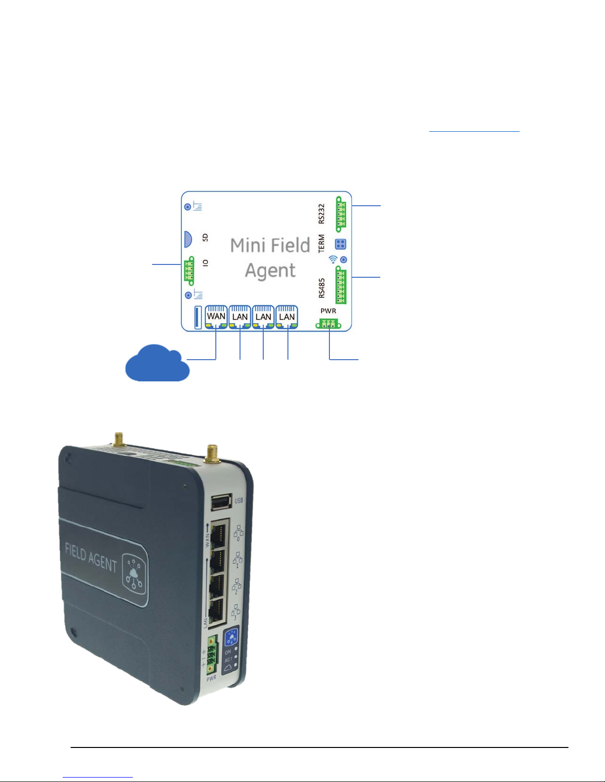
1.4 Mini Field Agent (MFA)
Discrete
Switched 10/100 Mbps
Ethernet Ports
Power Supply
RS-485 and CAN bus
RS-232 Serial
The GE Mini Field Agent* (MFA) module is a Machine to Cloud collector that securely forwards data to a Predix* Time
Series Database Service. The MFA is based on the ARM architecture and designed to meet low power, harsh environment
specifications for industrial use. It runs an embedded Linux® operating system and comes with Predix Machine pre-integrated
and ready to enroll in Predix EdgeManager. The Field Agent ecosystem enables end users ease of developing Predix solutions
using the MFA platform. The following figure depicts the typical installation of a MFA. The section Configure the Network
provides defaults IP addresses.
Input/Relay
Com Ports
Serial Com Ports
Features
• Predix Machine
• One Wide Area Network (WAN) Ethernet port
• Three Local Area Network (LAN) Ethernet ports with
• RS-485 hardware interface
• RS-232 hardware interface
• CAN bus hardware interface
• One discrete input
• One relay contact
• Optional cellular modem
• Optional Wi-Fi hotspot
built-in switch
Page 12

GFK-2993F 12
For public disclosure
1.4.1 MFA Specifi cat ions
2GB on-board flash
Humidity
Region
4G LTE Bands
3G WCDMA Bands
EU
1, 3, 7, 8, 20
1 (2100 MHz), 8 (850 MHz)
Hipot tested to 1202 V DC (equivalent of 925 V rms)
Note For the latest information, refer to the webpage at http://www.geautomation.com/products/field-agent
Item
Description
Processor
Memory
Ambient Temperature,
Real Time Clock Battery Battery backup for RTC, 6 years
USB Port USB 2.0
SD Card Slot One MicroSD card slot
Wi-Fi (Optional) 2.4GHz Wi-Fi, regional settings determined by catalog number
Cellular (Optional) LTE Cellular Modem, regional settings determined by catalog number
Ethernet Ports
RS-232
TI AM3352 32-bit ARM processor, 800MHz
512MB DDR3 RAM
-40°C to 70°C (0°C to 70°C ATEX), 5 to 95% non-condensing
Use above 55°C requires installation in a restricted access location
U.S./Canada 2, 4, 5, 7, 12, 13, 25, 26 2 (1900 MHz), 5 (850 MH z)
One unswitched Ethernet port, 10/100 Mbps
Three switched Ethernet ports, 10/100 Mbps
One RS–232 Serial Port (pluggable screw terminal)
Maximum cable distance is 15m
Maximum communication rate is 115.2 kbps
One RS–485 Serial Port (pluggable screw terminal)
RS-485
CAN bus
Discrete input
Relay contact
Operating System Embedded Linux built using the Yocto Toolchain
Operating voltage
Power consumption
Maximum cable distance: 305 m (1000 ft)
Maximum communication rate: 115.2 kbps
One CAN port (pluggable screw terminal)
Maximum cable distance is 40 meters
Maximum communication rate is 1 Mbps
1 x 24 V opto-coupled / isolated input, 10 mA nominal
Minimum ON = 1.4µs
Maximum OFF = 28 µs
1 x Output relay, DC (Form A normally open relay contact, 30W switching power)
30 V DC, 1A
Hipot tested to 1202 V DC (equivalent of 925 V rms)
9 to 30 V DC, nominal 24 V DC
4 Watts (167mA@24V DC) without cellular modem (ICMFA000000, ICMFA002xxx)
8.4 Watts (350mA@24V DC) with cellular modem (ICMFA001xxx)
Wire sizes: 22 to 16 AWG; Screw torque: 2 in-Ib
3-pin power plug
Temperature rating for copper wire: 80 °C
Wiring to power input terminals shall be limited to 30 meters in length
Page 13

GFK-2993F 13
For public disclosure
57-500HZ, 2.0g acceleration
Item
Housing dimensions 5.53 x 5.33 x 1.55 Inches (140.5 x 135.3 x 39.4 mm)
Mounting DIN rail or panel mount
Description
Certifications
Operational Vibration
Operational Shock
Mean Time Between Failures ICMFA000000: 415,750 hours (47.46 years)
Security Features
Protocols
Refer to the section Agency Certifications and Standards
IEC 600068-2-6
10-57Hz, 0.012"ppk displacement
IEC 60068-2-27
15g, 11ms (sine wave)
ICMFA001xxx: 396,295 hours (45.24 years)
ICMFA002xxx: 404,734 hours (46.20 years)
On-board Trusted Platform Module
Modbus TCP, OPC UA (built in)
Other protocols can be added using the Predix Machine SDK.
Page 14

GFK-2993F 14
For public disclosure
1.5 Embedded Field Agent (EFA)
The GE Embedded Field Agent (EFA) is available in two physical form factors: the Mark* VIe controller, which is part of the
ControlST fam ily of pr oduct s, a n d the CPE400 controller, which is part of the PACSystems* f ami ly of products. The EFA resides in
one of the virtual machines on the controller and uses the Ubuntu® operating system. It comes with Field Agent software including
Predix Machine pre-integrated and ready to enroll in Predix EdgeManager. While the EFA is essenti ally configured the s ame way
as an MFA, there are different Application and Configuration templates provided for the EFA. For instance, because the EFA has
more memory a nd a higher-performance CPU compared to the MFA , it can retai n more “Store and Forw ard” buff ered data in t he
event of tem porary los s of comm uni cati ons to th e cl oud. Therefore, the Store and Forward configuration files for the MFA and EFA
are different.
1.5.1 Mark* VIe IS4 2 0 UCSCH1A CPU w / Field Agent
The Mark* VIe UCSC EFA uses the IICS Cloud Port (f oun d on t he bot tom of th e UCS C) to bot h comm uni cat e to con trol lers t o g ath er
data, as well as to connect to the Predix Cloud. For more information about the UCSC itself, please see GEH-6721_Vol_II Mark * VIe
and Mark* VIeS Control Syst em s, Vol ume II: G ener al-purpose Applications.
1.5.2 PACSystems IC695CPE400 RX3i Rackless CPU w/ Field Agent
The CPE400 EFA uses the EFA Port (found on the bottom of the CPE400) to connect to the Predix Cloud. It uses an internal virtual NIC
to communicate with the controller to gather data. The CPE400 also contains a display, which is described in the EFA HW Instructions
portion of th is docum ent . For more information about the CPE400 itself , please see PAC Systems RX7i & RX3i C PU Refer ence Manual,
GFK-2222Y or later.
Page 15

GFK-2993F 15
For public disclosure
1.6 Virtual Field Agent (VFA)
The GE Virtual Field Agent (VFA) is a Virtual Machine that uses the Ubuntu operating system. It contains Predix Machine to allow
streaming data to the cloud or running applications locally. It also incorporates User Interfaces for configu ring networks and time
synchronization, getting Field Agent Product and Linux OS Updates, and checking status and running commands. While the VFA is
essentially configured the same way as an MFA or VFA, th ere are different A pplication an d Configurati on templates provided for the
VFA, because these templates are associated with a s pecific v ersion of Predix Mach ine. Cu rrently the Virtual Field Agent is normally
distributed as one of the possible Virtual Machines on a Control Server. To learn more about Con trol Servers, please s ee GEH-6851
Control Server – High Availability (HA) Maintenance Guide and GEH-6852 Control Server – Simplex Maintenance Guide.
Page 16
GFK-2993F 16
For public disclosure
2 MFA Hardware Instructions
2.1 Internal Components
Caution
The MFA module is shipped with a battery pre-installed. The battery holder is located below the Supercap, and can be
replaced by opening the top cover.
To replace the battery
1. Power OFF the MFA Module.
2. Wait for 1 minute.
3. Open the top cover by loosening the four screws on the edges.
4. Use a small flat-head screw driver to gently pry out the old battery.
5. Insert the new battery.
Warning
The only user-serviceable components in the Mini Field Agent are the Real Time Clock
Battery and cellular SIM card. Do not remove or alter any other components on the Mini
Field Agent.
Replace battery only with Rayovac BR2032 or part IC690ACC001B or later. Use of
another battery may present a risk of fire or explosion.
Battery may explode if mis t reated. Do not recharge, disassemble, heat above 100 °C
(212 °F) or incinerate.
The MFA module has an optional cellular modem. The SIM is available as a pre-installed option or may be installed by the
customer. The SIM card holder is located underneath the cellular modem and can be installed by opening the top cover and
removing the cellular modem.
To install a SIM Card
1. Power OFF the MFA Module.
2. Wait for 1 minute.
3. Open the top cover by loosening the four screws on the edges.
4. Remove the cellular modem by removing the two screws, tilt the modem up and slide out of the connector.
5. Slide the SIM card holder latch toward the Ope n p osition and flip it open.
6. Slide the SIM card into the holder so that the contact s will face down when closed and with the notched e nd extending out
of the holder.
7. Close the SIM card holder and slide the latc h to the Locked position.
Page 17

GFK-2993F 17
For public disclosure
2.1.1 Installation
There are two different mounting options for the MFA: DIN Rail Mount or Panel Mount. The ICMFAACC001 MFA Panel
Mounting Kit is required to use the Panel Mount option. After mounting the MFA, connect it to the facility network using
standard Ethernet cables. The LAN interface should be connected to the local area network containing one or more industrial
devices. The WAN interface should be connected to a network with access to the Internet.
Page 18
GFK-2993F 18
For public disclosure
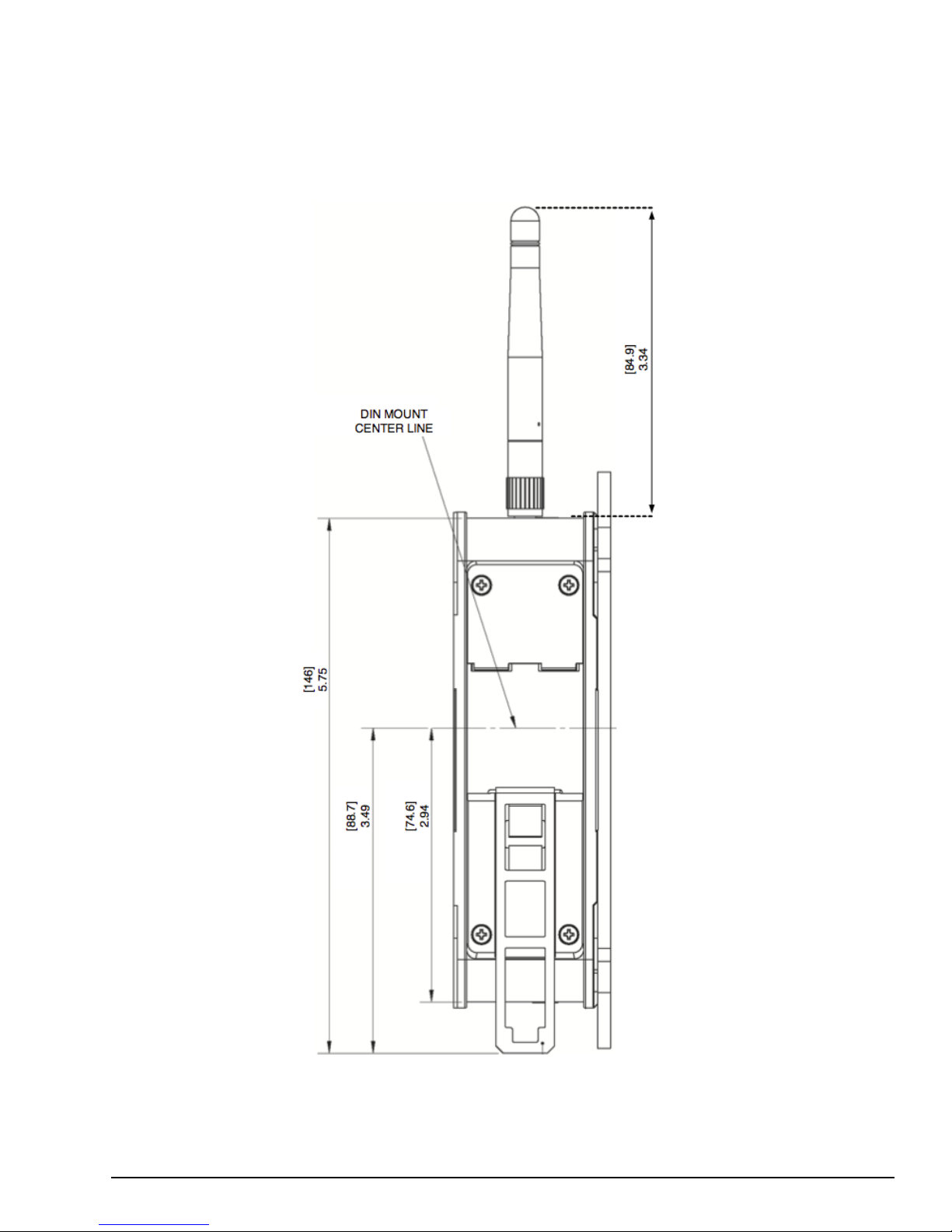
2.1.1.1 DIN Rail Mount
The MFA comes equipped with a DIN Rail mounting clip as displayed in the following figure. For DIN Rail mounting, pull
the clip down and lock it in place. Place the unit on the DIN rail, and then push the clip up to secure it. The optional panel
mounting plate should not be attached because it will prevent DIN rail mounting.
Page 19
GFK-2993F 19
For public disclosure
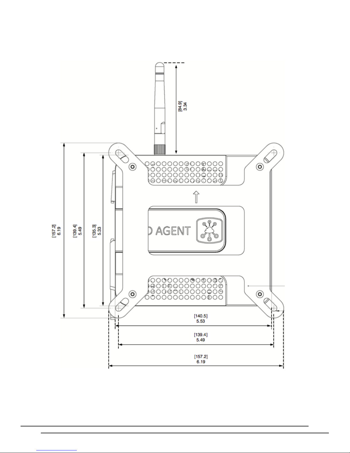
2.1.1.2 Panel Mount
To panel mount the MFA module, attach the ICMFAACC001 panel mount plate to the side of the MFA module using the four
M3 screws included with the mounting kit. Attach the panel mount plate in the orientation as displayed in the following
figure. The screw size for each panel mount tab is recommended to not exceed M5.
Page 20
GFK-2993F 20
For public disclosure
2.1.1.3 MFA Interface Details
Front View
Top View
Cellular Antenna
MicroSD slot
Local Field I/O
DIN Rail
RS-232
RS-485
Termination Jumper for CAN
Wi-Fi Antenna
Ground
Rear View
Bottom View
USB
Ethernet
Push
Status
Note Refer to Mini Field Agent (MFA) Important Product Information (GFK-2997) for version-specific interface details.
The following figure displays all four sides of the MFA module with details for connections.
Connections
(for GE internal use only)
(on applicable models)
Interface
Mounting Clip
Connection
Connection
(on applicable models)
Interfaces
Button
LEDs
(rightmost 2 contacts)
Page 21
GFK-2993F 21
For public disclosure
2.1.1.4 Power Requirements
The MFA is powered by a DC Power Supply (9 to 30 V dc, nominal 24 V dc). Power for the MFA shall be provided by a
Class II power supply marked as "double insulated", Limited Power Source (LPS), or a SELV source with a minimum 32 V
dc listed fuse with 3 A max rating. Power for the relay output and discrete input shall be provided by an isolated source.
Reversing input power polarity might cause damage to the MFA.
Caution
The IC690PWR024 (Selectable
power requirements of the MFA.
The ICMFAACC002 is rated for 100-240
attachment of the AC power cord. The ICMFAACC002 may be adapted to local power by using a desktop computer-style
AC power cord (with an IEC-60320 C13 connector on one end and the correct AC mains plug on the other).
Caution
Grounding
There are two ground connec tions on the Mini Field Agent. One is loca ted on the front power connector and the other is a
chassis screw located on the bottom o f the unit. BOTH grounds must be connected to earth ground to comply with CE
performance requirements. Ground wires should be kept as short as possible and tied to a common cabinet/equipment ground
point. It is recommended to use #14AWG stranded wire for the chassis ground.
115/230V
The use of the ICMF A A C C 00 2 in permanent installations shall be i n accordance
with the National Electric Code (NEC), the Canadian Electric Code (CEC), or with
the authority hav ing jurisdiction.
AC input, 24V dc @ 5A Output) DIN Rail mountable power supply meets the
V
ac and 47-63 Hz input, and features an IEC-60320 C14 inlet plug for
Page 22
GFK-2993F 22
For public disclosure
2.1.1.5 Pin Definitions
1
K1-A
4
IN-
7
Z /RTS
1
TX
Note Refer to the section MFA Interface Details
Connector
Function
for a figure that displays the physical locations of each pin.
Pin Number
Description
PWR
IO
CAN bus
RS-485
RS-232
Power connector
(9 to 30 V dc)
Normally Open relay contact output, 30 V dc, 1 A resistive load
+24 V Opto-coupled Input, 10 mA
Serial
Serial
Serial
1 Ground
2
3
2 K1-B
3 IN+
1
2
3 Ground
4 A /RX
5 B /CTS
6 Y /TX
2 RX
3 GND
4 RTS
5 CTS
Negative Voltage
Positive Voltage
CAN_H
CAN_L
2.1.1.6 Network Configuration
Note Refer to the section
Ethernet interfaces.
The default WAN and LAN IP addresses of the Mini Field Agent are displayed in the following table.
Item
IP Address Obtain using DHCP 192.168.1.100
Subnet Mask Obtain using DHCP 255.255.255.0
Gateway Obtain using DHCP Not set
WAN connects to the uppermost RJ-45 connector. LAN connects to the three lower RJ-45 connectors and they are switched
internally.
MFA Interface Details
for a figure that displays the physical locations of the LAN and WAN
WAN
LAN
Page 23

GFK-2993F 23
For public disclosure
2.1.2 Push Button and LEDs
The front panel of the MFA contains a blue push button and three indicator LEDs. The LEDs
have different behaviors depending on whether the push button is being held. When the push
button is not being used, the LEDs behave as follows.
ON LED:
• Blinking green indicates Predix Machine is starting.
• Solid green indicates Predix Machine is running. The ON LED must be solid before
attempting to connect to the Predix Machine Web Console over wired Ethernet or the
Wi-Fi hotspot .
The Push Button is used for enabling or disabling Configuration Mode, performing a graceful reboot of the MFA, or
performing a factory reset depending on how long the button is held and released. These features and the corresponding
impact on the LED behavior are documented in the section, Push Button Operations
Each of the four RJ-45 Ethernet connectors contains two LEDs. The green LED indicates an Ethernet connection has been
established. The yellow LED indicates packet traffic.
• Slowly fading in and o ut indicates the MFA is in Configuration Mode .
ACT LED:
• Blinking orange indicates that data is being received from a configured Machine
Adapter.
Cloud LED:
• Blinking blue indicates Predix Machine is not connected to the Predix Cloud.
• Solid blue indicates Predix Machine is connected to the Predix Cloud.
.
Page 24
GFK-2993F 24
For public disclosure
2.2 Push Button Operat ions
20 – 24.9 seconds
All LEDs slow blink
None
The Push Button on the front of the Mini Field Agent (above the green ON LED) is used for the following activities based on
how long the Push Button is held and released. Each time interval that corresponds to an operation has a unique fast blink
pattern that indicates releasing the Push Button at this time will perform an operation. In between these time intervals, all
LEDs blink slowly. Releasing the Push Button during a time interval when all LEDs are blinking slowly or when the Push
Button is held for 30 or more seconds will result in no operation and the LEDs will return to their normal behavior described
in the section, Push Button and LEDs
Time Interval the Push Button
Is Held and Released
< 5 seconds Normal LED Behavior None
5 – 9.9 seconds Green ON LED fast blink
10 – 14.9 seconds All LEDs slow blink None
15 – 19.9 seconds
25 – 29.9 seconds All LEDS fast blink
30+ seconds Normal LED Behavior None
.
LED Behavior
Green ON and Orange ACT LEDs fast blink
Operation on Release
Configuration Mode
Reboot
Factory Reset
2.2.1 Configurat ion Mode
If the Push Button is released during this time interval, the Mini Field Agent will enable Con figuration Mode. In Configuration
Mode, a Wi-Fi hotspot is enabled that can be used to enroll the Mini Field Agent in Predix EdgeManager and read device
diagnostic s using an iPhone® app . While in Configuration Mode, the green ON LED fades in and out slowly. The orange ACT
LED and the blue Cloud LED will both continue to operate normally according to the state of the Mini Field Agent.
Configuration Mode can be disabled by repeating the same steps taken to enable it, or by waiting one hour for Configuration
Mode to automatically disable. When Configuration Mode is disabled, the LEDs will return to their normal behavior described in
the section,
Secure Deployment Guide.
Wi-Fi Hotspot Property
SSID mfa_<7-digital serial number> (e. g. mfa_t d7 s0sx)
Encryption Type WPA2-PSK
Password
Router IP Address 192.168.2.1
Router IP Subnet Mask 255.255.255.0
Number of Concurrent Client Connections 2
Client IP Address Assignment Range
DHCP Lease Duration
Maximum Enabled Duration
The GE Energy Connections Field Agent Manager iPhone app is available to GE Employees on the GE App Store. When
using the Field Agent Manager iPhone app to enroll or configur e a Field Agent, the wizard instructs the user to enable
Configuration Mode using the Push Button and connect to the Wi-Fi hotsp ot in the iPhone ’s Settings page b efore p roceeding
with enrollment.
Push Button and LEDs
. Security considerations for the Wi-Fi hotspot can be found in GFK-3009 Field Agents
Value
Printed on MFA label
192.168.2.20 - 192.168.2.21
1 hour
1 hour
Page 25

GFK-2993F 25
For public disclosure
2.2.2 Reboot
If the Push Button is released during this time interval, the Mini Field Agent will perform a graceful reboot and will return to
normal operation.
2.2.3 Factory Reset
If the Push Button is released during this time interval, the Mini Field Agent will perform a factory reset. This operation will
take several minutes, after which the Field Agent will reboot. Once the green ON LED is solid it will be possible to log into
the Predix Machine Web Console and configure the Field Agent.
On the first boot following a factory reset, Predix Machine will generate
cryptographic keys used for communication. It is critical that the Mini Field Agent not
be powered down during these operations to prevent key corruption that may require
another factory reset to resolve. Do not power cycle the Mini Field Agent on the first
CauCau
tion
boot after a factory reset until the green ON LED is solid.
Page 26

GFK-2993F 26
For public disclosure
2.3 Field Agent Sales Catalog
2.3.1 GE MFA Orderable I tem s
Catalog Number
ICMFA000000 Mini Field Agent
ICMFA001US0 Mini Field Agent with Cellular and Wi-Fi certified for U.S./Canada
ICMFA001US1 Mini Field Agent with Cellular and Wi-Fi certified for U.S./Canada, and AT&T SIM card
ICMFA002US0 Mini Field Agent with Wi-Fi certified for U.S./Canada
ICMFA001EU0 Mini Field Agent with Cellular and Wi-Fi certified for European Union
ICMFA001EU1 Mini Field Agent with Cellular and Wi-Fi certified for European Union, and AT&T SIM card
ICMFA002EU0 Mini Field Agent with Wi-Fi certified for European Union
2.3.2 MFA Included Items
The following items are included with the MFA (not ordered separately).
Accessory Item
Description
Description
Wi-Fi Antenna & Cable Assembly
(Wi-Fi models only)
Cellular Antenna & Cable
Assemblies (Cellular models only)
Battery Rayovac make BR2032-BA Lithium 20mm 3V 195mAh Coin Cell battery (-40C to +85C)
Taoglas GW.11.A153 dipol e antenna with Taoglas CAB.628 IPEX MHF1 to SMA(F) RP
cable
Nearson T6155AM-LTE-S LTE antennae with Taoglas CAB.618C and CAB.011 IPEX
MHF1 to SMA(F) cables
2.3.3 MFA Accessories
The following accessories can be ordered separately.
Catalog Number
ICMFAACC001 Mini Field Agent Panel Mounting Kit
ICMFAACC002 24V Power Supply Pre-wired with Connector
IC690PWR024 Selectable 115/230 V AC Input, 24 V DC 5A Output, DIN Rail Mount Power Supply
ICMFAMGTM1YR Annual Device Management Fee
ICMFADATA1GB Annual Cellular Connectivity Fee
ICPREDIXSERVICES Predix Services as Consumed
Description
Page 27

GFK-2993F 27
For public disclosure
2.4 Agency Certifications and Standards
5969A-TIWI101
Group
Refer to Mini Field Agent (MFA) Installation and Maintenance Requirements (IMR) (GFK-2998) for conformance to these
standards.
Description
Marking
Comments
North America Safety for Information
Technology Equipment
North America Safety for Programmable
Controller for use in Hazardous locations
Class 1 Division 2 Groups ABCD
Class 1 Zone 2 Gas Group IIC
North American Radio Equipment
European Radio Equipment
European Restriction of Hazardous
Substances (RoHS)
European Safety for Explosive
Atmospere
Equipment Group II, Category 3, Gas
Contains FCC
TFB-TIWI-01
Contains
IC:
ID:
Certification by Underwriters Laboratories: UL 61010-1,
UL
61010-2-201, UL 60950-1, UL 60079-0, UL 60079-15,
and ISA-12.12.01-2013. CSA C22.2 No. 61010-2201, CAN/CSA C22.2 No. 60950-1-07, CSA C22.2
No. 213 M1987, CAN/CSA-C22.2 No. 60079-0, and
CAN/CSA-C22.2 No.
60079-15.
Equipment Authorization issued by Telecommunication
Certification Body under authority of Federal
Communications Commission (FCC) and Industry
Canada (IC) for intentional transmitters
EU-Type Examination by Notified Body (#0673) to
European
Radio Equipment Directive 2014/53/EU
Manufacturer’s declaration of conformity in accordance
with
European RoHS Directive (2011/65/EU)
Certification in accordance with to European ATEX
Directive
2014/34/EU
International Safety for Explosive
Atmosphere
European Waste & Collection
China Restriction of Hazardous
Substances
Certification in accordance with the IECEx s cheme and
in compliance with IEC 60079-0 & IEC 60079-15
Compliance with European WEEE Directive
2002/96/EC Amended by 2008/34/EC
Compliance with “Management Methods for the
Restriction of the Use of Hazardous Substances in
Electrical and Electronic Products”. (Jan 21, 2016)
Declaration Table provided with equipment.
Page 28

GFK-2993F 28
For public disclosure
2.4.1 Federal Communic a t ions Commission (FCC)
Changes or modifications not expressly approved by the party responsible for
compliance could void the user's authority to operate the equipment.
Caution
Page 29

GFK-2993F 29
For public disclosure
2.5 Replacement and Spares
Replacement parts may contain static-sensitive components. Therefore, GE ships replacement parts in anti-static bags. When
handling electronics, make sure to store them in anti-static bags or boxes and use a grounding strap.
Caution
Warning
2.5.1 Replacement Procedure
System troubleshooting should be at the module level. The failed module should be removed and replaced with a known good
spare. The failed device should be returned to GE for repair. Do not attempt to repair it on site.
Caution
To prevent component damage caused by static electricity, treat all boards with staticsensitive handling techniques. Wear a wrist grounding strap when handling boards or
components, but only after boards or components have been removed from
potentially energized equipment and are at a normally grounded workstation.
In addition to information provided here, always follow all wiring and safety codes
that apply to your area or your type of equipment. For example, in the United States,
most areas have adopted the National Electrical Code standard and specify that all
wiring conform to its requirements. In other countries, different codes will apply. For
maximum safety to personnel and property you must follow these codes. Failure to do
so can lead to personal injury or death, property damage or destruction, or both.
To prevent equipment damage, do not remove, insert, or adjust board connections
while power is applied to the equipment.
To replace the MFA
1. Lock Out Tag Out (LOTO) the equipment to isolate power sources.
2. Disconnect the incoming power plug.
3. Disconnect the Ethernet cables.
4. Remove the screws holding the MFA in place.
5. Install the new MFA by reversing steps 4 through 1.
Page 30

GFK-2993F 30
For public disclosure
2.5.2 Renewals and Spares
Renewals and spares (or those not under warranty) should be ordered by contacting the nearest GE Sales or Service Office, or
an authorized GE Sales Representative.
Prior to ordering a replacement part:
• Identify the part (e.g. ICMFA000000-AAAA)
• Determine if the part is under warranty
While ordering, be sure to include the complete part number and revision letter. All digits are important when ordering or
replacing any device. The factory may substitute newer versions based on availability and design enhancements, however, GE
ensures backward compatibility of replacements.
Page 31

GFK-2993F 31
For public disclosure
Notes
Page 32

GFK-2993F 32
For public disclosure
3 EFA Hardware Inst ructions
Note: The EFA will only respond to ping messages when it is in configuration mode.
3.1 Mark* VIe IS420UCS CH1A CPU w/ Field Agent
This section only describes the hardw are aspects of the Mark VIe UCSC that explicitly pertain to the Field Agent functionality. For
general information about the UCSC hardware, please see GEH-6721_Vol_II Mark VIe and Ma rk V IeS Co ntr ol Sys tems , V olum e II:
General-purpose A pplic ati ons.
3.1.1 UCSC EFA – Network Configuration
The UCSC EFA uses the IICS Cloud Port (found on the botto m of th e UCS C) t o both comm un icat e to
controllers to gather data, as w ell as to connect to th e Predix Cloud. The default IP Address assign ed to
this is 172.31.0.100, s ubn et m ask 255.255 .0. 0. For more information on changing the IP Address, please
see the Configure the N etw ork
section of this document.
Page 33

GFK-2993F 33
For public disclosure
3.1.2 UCSC EFA – Push Button a nd LE D
LED
LED State
Operating State
FAOK
On Green
Field Agent Running and Connected to Cloud.
Blinking Green
Field Agent Starting.
command has been received.
Off
Field Agent Off.
Button Hold Time
Command
Description
5-10 seconds
Toggle Configurat ion M ode
Enable or Disable acces s to th e Web Con sole:
Console.
15-20 seconds
Reboot Field Agent
This will restart the Fi eld Ag ent operat ing syste m and P red ix Machin e
without affecting the cont rol ler.
25-30 seconds
Factory Reset
This will reset the IP Ad dre ss ba ck to the def ault, and remov e Pr edix
Please wait until t he FA O K LE D is on so lid b efor e cy cling power.
The UCSC Hardware only contains one push button and one LED that aff ect/reflect information
about the EFA.
Field Agent Status Indic ators (LEDs )
OR
Field Agent Running but NOT Connected to Cloud.
OR
PHY PRES push button is being pres sed and LED is
blinking once a second to help the user count seconds for
initiating the desired c ommand.
OR
Fast Blink to acknowledge PHY PRES push button
PHY PRES Push Button Commands
• If the Web Consol e is disab led, the n this will enable access to the Web
Console for one h our.
• If the Web Consol e is enable d, then th is wil l dis able a cces s to t he Web
Enrollment infor mation from the Fiel d A gent. O n the fir st bo ot foll ow ing a
factory reset, Pre dix M achine wil l gener ate crypt ograph ic keys used for
communication.
It is critical the Field Age nt is not pow ered dow n dur ing th ese o per ations
to prevent corrup tion t hat may re quir e anot her factory rese t t o res olve.
Page 34

GFK-2993F 34
For public disclosure
3.2 PACSystems IC695CPE400 RX3i Rackless CPU w/ Field Agent
This section only describes the hardware aspects of the CPE400 that explicitly pertain to the Field Agent functionality. For general
information about the CPE400 hardware, please s ee PACSyst ems RX7i & RX3i CPU Reference Manual, GFK-2222Y or later.
3.2.1 CPE400 EFA -- Network Conf iguration
The CPE400 EFA us es th e EFA Port (fou n d on t he bot tom of the C PE400) to c on ne ct to t he Pre dix
Cloud. It uses an internal virtual NIC to communicate to the controller to gather data. The defau lt IP
Address for th e EF A Cl oud Port is 172. 31.0. 10 0, su bne t m ask 255.255 .0.0. Fo r m ore in f orma tion on
changing the IP Address, please see th e Confi gure t he Ne twor k
section of this document.
Page 35

GFK-2993F 35
For public disclosure
3.2.2 CPE400 EFA – LED, Display, and Push Buttons
LED
LED State
Operating State
FAOK
On Green
Field Agent Running and Connected to Cloud.
Blinking Green
Blink at 0.5 Hz: Field Agent Starting.
Blink at 1 Hz: Field Agent Running.
Off
Field Agent Off.
Push Button
Function
Moves the cursor to the next item in the display, including moving to
display hierarchy.
Executes the currently s elected item in the display. This could cause
OK or Cancel.
Menu Item
Description
EFA Status
Shows the current state of t he Fi eld A gent, as follow s:
• Cloud Connected: T he F ield Agent is R unnin g and conne cted t o t he cl oud.
Network Config
Shows network interf ac e info rma tion for th e Fiel d Ag ent, i nclud ing IP Ad dress, Sub net M ask, Ga te way ,
These settings are chan ged a s described in the se ction, Conf igu re the N etw ork.
Commands Sub Menu
Config Mode
Enter Configuration M ode, e nabl ing ac cess to th e Web Cons ole f or one h our .
FA Reboot
This will restart the Fi eld Ag ent operat ing syste m and P red ix machin e withou t a ffecti ng the contr ol ler.
Factory Reset
This will reset the IP Ad dre ss ba ck to the def ault, and remov e Pr edix Enrol lment infor mat ion fro m the
blinking at 1Hz) before cycling p ower.
The CPE400 Hardware only contains one LED an d a four-line display (m ani pul ated by tw o pu sh bu tton s)
that affect/reflect information about the EFA. The description of th e Di spl ay c onte nts be low only cov ers
items related to the Field Agent.
Field Agent Status Indic ators (LEDs )
Display Navigation Push Buttons
DISP
SEL
the next page if more than one page exists for a given level in the
the display to navigate to another location in the hierarchy, or it could
cause a command to be executed if a command is currently selected.
Before a command is executed, the user is given the choice to select
FA Settings Display M enu
• Off: The Field Ag ent i s Off.
• Starting: The Fiel d Ag ent i s start i ng.
• Not Connected: The Fi eld Age nt is R unnin g, but not connect ed to the cloud.
MAC Address, and IPv 6 Address.
Field Agent. On the fir st bo ot f ollow ing a fac tory r eset , Pred ix Machine w il l gener ate cry ptogr aph ic k eys
used for communicat ion.
It is Critical th e Fiel d Agent i s not power ed dow n dur ing th ese o perat ion s to pr event cor rupti on th at may
require another fa ctory reset to r esolv e. Plea se w ait until the EFA Status is Not Connected (FAO K LED
Page 36

GFK-2993F 36
For public disclosure
3.3 GE EFA Orderable Items
Catalog Number
Description
ICCP4MGMT1YR
ICPREDIXSERVICES Predix Services as Consumed
Annual Device Management Fee
Page 37

GFK-2993F 37
For public disclosure
4 VFA Instructions
This section describes the Network Configuration and VM Deployment for Virtual Field Agents. Currently the Virtual Field Agent is
normally distributed as one of the possible Virtu al Machin es on a Con trol Server. To learn m ore about Control Serv ers, please see GEH-
6851 Control Server – High Ava il abili ty ( HA) Mai ntenan ce Gui de and GEH-6852 Control Se rv er – Simplex Maintenance G uide
4.1 Network Configur ation
The VFA is configured with three networks; a WAN, LAN1 and LAN2. Here are th e default I P addresses.
Item
IP Address
WAN
Obtain using DHCP 172.16.101.150 172.16.201.150
LAN1 LAN2
Subnet Mask
Network Interface
NOTE: It is important that the networks above are mapped to the identif ied netw ork interf ace. If either VMware vCenter® or VMware
vSphere® Client is used to generate the Virtual Machine, then the above network in terfaces sh ould autom atically be used, w ithout the
user needing to do anything special. How ever, if VMware Workst ation Pro™ is used, it may default the network interfaces differently.
In this case, after the user has g enerated the Virtu al Machin e, they should power down the Virtual Machine. Then edit the vm x file to
make sure the pcislotnumbers correspond to the en s num bers shown in t he table above. If ch ang es are made, m ake sure th at there are no
duplicate pcislotnumbers; they may need to be chang ed for other hardw are. For m ore inf ormation on ch anging th e IP Address, pleas e
see the Configure the N etw ork
Obtain using DHCP 255.255.240.0 255.255.240.0
ens33 ens34 ens35
section of this document.
4.2 Configuration Mode
Configuration Mode allows access to the Web Console. Configuration Mode is always enabled on the Virtual Field Agent.
4.3 Virtual Machine Deployment
The VFA Virtual Machine is intended to be run using VMware ESXi™. There are three m ain files that comprom ise a Virtual Machine
Deployment, a *.vm dk (Virtual Machine Disk Format), a *.ovf (Open Virtualization Format) and a *.mf file (Contains a security hash
corresponding to the .vmdk and .ovf files). If instructions are needed for how create a Virtual Machine from this collect ion of f iles, then
please refer to the section “VM Im port from OVA or OVF File” in either th e GEH-6851 Control Server – High Availability (HA)
Maintenance Gui de or GEH-6852 Control Ser ver – Simplex Maintenance Guide. The HA Control Server uses VMware vCenter. The
Simplex uses VMware vSphere Client.
4.4 Virtual Machine Snapshot s
Note, once the VFA is up and working it is recommended that a snapshot be made of the VM for backup purposes.
4.5 GE VFA Orderable Items
Catalog Number
ICVFAMGMT1YR Annual Device Management Fee
ICPREDIXSERVICES Predix Services as Consumed
Description
Page 38

GFK-2993F 38
For public disclosure
5 Getting Started with the Field Agent
5.1 What’s the Minimum I Need to Do to Get Going?
This lists the minimum steps that need to be done to start using a Field Agent. The details of how to perform each step are
described elsewhere in this document and are just referenced here.
1. Register the Field Agent in the Customer Portal (See Register the Field Agent
2. Start the Field Agent (See Start the Field Agent).
3. Log into the Web Console (See Log into the Web Console).
4. Configure the Network (See Configure the Network).
5. Configure Time Synchronization (See Configure Time Synchronization).
6. Update the Field Agent (See Update the Field Agent).
7. Enroll Field Agent in Predix Cloud (See Enroll Field Agent in Predix Cloud). Note, even if you do not plan to
stream data to the cloud, it is still required that you enroll your Field Agent.
8. If you plan to stream data to the cloud:
a. Create Configuration (See Configuring Data Collection and Sending Data to the Cloud
b. Deploy Configuration (See Configuration Management).
9. If you plan to deploy your own applications to run on the Field Agent:
a. Create an application. Information about how to write and deploy a custom machine adapter or data processor,
including sample Predi x Machine application source code, can be found by searching f or “Predix Machine SDK
Overview” in https://docs.predix.io
b. Deploy Application (See Application Management).
.
).
).
5.2 Register the Field Agent
Field Agents must be registered on the Customer Portal under the Assets tab. The process for registering a Field Agent, which
includes the process of requesting a new EdgeManager tenancy if needed, is documented in GFK-3018, Field Agent
Registration Guide. This documentation can be found on the Landing Page for each Field Agent type referenced in
Documentation.
Related
Page 39

GFK-2993F 39
For public disclosure
5.3 Collect Enrollment and Configuration Information
based on Field
Data Source IP address and
Modbus TCP Slave, etc.)
names or register addresses
Before enrolling and configuring a Field A gent, it is often useful to first collect all of the enroll ment i nformation (URLs, Field
Agent serial numbers) and configuration information (Time Series Ingestion URL, Zone ID, etc.) into a single plac e to
reference through the process. It is recommended to fill out as much of this table as possible before proceeding and referencing
it in subsequent steps.
Resource
Where To Find It
Value
EdgeManager URL
(Certificate Enrollment URL)
UAA URL
OAuth Enrollment URL
(if not using Certificate
enrollment)
Device Name
Device ID
Predix Machine Web
Console URL
Network Proxy and Port
(if required)
Port (OPC UA Server,
Data tag names and
corresponding variable
Data subscription name(s)
Response e-mail from Field Agent Registration
EdgeManager Settings page
EdgeManager Settings page
User Selected
User Selected, although typically the Device
Serial Number printed on the Field Agent
Section
Agent type and user-selected IP address
User-specified based on target network
User- specified based on target network
User- specified based on target network
User-specified based on target network. Data
tags may be divided into multiple subscripti ons.
Log into the Web Console
Time Series Ingestion URL
Time Series Zone ID
Response e-mail from Time Series database
activation request
Response e-mail from Time Series database
activation request
5.4 Start the Field Agent
After providing the Mini Field Agent or the c ontroller with Embedded Field Agent with power, the Field Agent will begin to
boot. The green ON LED (for MF A) or FAOK LED (for EFA) will begin blinking when Predix Machine is starting, which
is a process that can take approximately one minute. For the MFA, th e green ON LED will turn solid once Predix Machine
is running. For the CPE400, the FAOK LED will blink faster once Predix Machine is running, and the Display will
indicate a FA Status of “Not Connected”. Once Predix Machine is running, the Web Console is accessible for configuring
and enrolling the Field Agent.
For the Virtual Field Agent, power on the Virtual Machine. There is no associated LED. Instead, when the Field Agent is
up you should be able to access the Web Console.
Default US-West URL:
wss://gateway-predix-data-services.run.aws-
usw02-pr.ice.predix.io/v1/stream/messages
Default US-East URL:
wss://gateway-predix-data-services.run.asv-
pr.ice.predix.io/v1/stream/messages
Page 40

GFK-2993F 40
For public disclosure
5.5 Log into the Web Console
To log into the Predix Machine Web Console:
1. Connect a computer to the appropriate port on th e Field Agent.
a. For an MFA, use LAN port 1, 2, or 3.
b. For an EFA use the EFA or IICS Cloud Port on the bottom of the device.
2. Configure the computer’s network adapter to be an address on the Field Agent’s network.
3.
4. (EFA Only) Enable access to the Web Console using the process described in section UCSC EFA – Push Button and
Note Browsing to the Web Console too soon may result in seeing an Authentication Required or similar drop-down/pop-
up dialog. Entering a user name and password into this dialog will not permit a log-in to the Web Console. Wait approximately
1-2 minutes for FA software t o be fully up and running and then re-attempt to browse to the Web Console. Closing the current
browser tab or window may also be required.
c. For a VFA, use LAN1 or L AN2
a. The MFA’s default LAN IP Add ress is 192.168.1.100, subnet mask 255.255.255.0. Therefore, use another
address on the 192.168.1.x network. For example, use 192.168.1.101 with subnet mask 255.255.255.0.
b. The EFA’s default LAN IP address is 172.31.0.100, subnet mask 255.255.0.0. Therefore, use another address
on the 172.31.x.x network. For example, use 172.31.0.101 with subnet mask 255.255.0.0.
c. The VFA’s default LAN1 IP address is 172.16.101.150, subnet mask 255.255.240.0. The VFA’s default LAN2
IP address is 172.16.201.150, subnet mask 255.255.240.0.
Confirm that Predix is up and running, so that the Web Console will be available.
a.
For an MFA, verify that the “ON” LED is solid green.
b.
For a CPE400 EFA, exa mine the OLED di splay, under “F A Settings”. It should say either “Not Connected” or
“Cloud Connected” if Predix is fully up and running.
c.
For a Mark V Ie there is no concl usive inspection only metho d to confirm that Predix is up and running. If the
“FA OK” LED is on soli d green, then P redix is up and running and the Web Console will be available .
However, if the “FA OK” LED is blinking at a 1 Hz. Rate, then it could mean either that Predix is still
starting, and so the Web Console will NOT be available until it is up, or the blinking could mean that Predix
Machine is up and running, a nd currently receiving data from a configured Machine Adapter, but is not
connected to the Cloud. In this case then the Web Console WILL be available.
d.
For a VFA there is no LED to check if Predix Machine is running—just attempt to connect to the Web
Console.
LED or CPE400 EFA – LED, Display, and Push Buttons.
5. Browse to the Field Agent’s Web Console. The Google Chrome bro wser is recommended for accessing the Web
Console.
a. For an MFA use https://192.168.1.100:8443/system/console
b. For an EFA use https://172.31.0.100:8443/system/console
6. Since the Web Console uses a self-signed certificate, the browser will warn that the connection is not private.
c. For a VFA use https://172.16.101.150:8443/system/console or https://172.16.201.150:8443/system/console
When prompted, accept the connection.
Page 41

GFK-2993F 41
For public disclosure
7. Login using the default credentials.
• Default User Name: predix
• Default Password: predix2machine
8. A prompt to change the default password
displays. Complete the form to change the default
password. The password complexity requirements
display if the chosen password if not sufficiently
complex. After changing the password, log in using
the new password.
Note If the Web Consol e password is forgotten or lost, use the Factory Reset feature to restore all Field Agent settings,
including Web Console password, to factory-default values .
9. Verify that the Log Service page displays, which indicates a successful login. Note that while the underlying Predix
Machine log file logs all events in UTC (Coordinated Universal Time), all log events displayed in the OSGi Log Service are
converted to and displayed in local tim e using the time zon e of the com puter running th e browser used to view th e Log Service.
Note After some idle time, the Web Console will timeout. If this occurs, the user will need to return to the main page to log
back into the console. Session timeout does not automatically redirect the console back to the login page.
Page 42

GFK-2993F 42
For public disclosure
5.6 Configure the Network
Field Agent Type
Default WAN Setting
Default LAN1 Setting
Default LAN2 Setting
MFA
DHCP
192.168.1.100,
N/A
EFA
172.31.0.100,
subnet mask 255.255.0.0
N/A
N/A
VFA
DHCP
172.16.101.150,
subnet mask 255.255.240.0
172.16.201.150,
subnet mask 255.255.240.0
5.6.1 IP Addresses
The Mini Field Agent has four p hysical Ethernet ports, one of which is designated to be a WAN. The Embedded field
agent only has one physical po r t, labelled either IICS Cloud Port or EFA, and it is designated to be a WAN. The
following are the default settings for these networks:
subnet mask 255.255.255.0
By default, the Mini Field Agent’s WAN interface is set to acquire an IP address from a DHCP server on the network. The
network interface settings that were automatically obtained from the DHCP server can be displayed in the Web Console.
5.6.1.1 To Identify/Change an IP Address
1. From the Web Console, navigate to the Technician Console, Network Configuration page. Note that there will be
three tabs (WAN, LAN, and Ce llular ) for an MFA, only a single tab (WAN) for an EFA, and three tabs (WAN, LAN1,
and LAN2) for a VFA.
2. To identify the DHCP assigned address for an MFA or VFA, select the WAN tab, then click the Query Current Status
button.
Page 43

GFK-2993F 43
For public disclosure
3. To identify a DHCP assigned address for a CPE400 EFA, use the Display on the front of the CPE400. Navigate
to FA Settings, and then to Network Config. At this time, it is not recommended to use DHCP for a UCSC
EFA, since there is no way to determine what address was assigned to the EFA.
4. To change an IP Address, select the appropriate tab (WAN or LAN). Then select the radio button Use the
following IP address, enter the desired IP address and network mask, and click the Save button. When the IP
Address is c hanged, the Web Console session will end after the Save button is pressed and a new session will need
to be started by browsing to the Web Console URL using the newly chosen static IP address.
Note The DNS servers can also be configured to be obtained automatically or specified statically.
Note The MFA only supports either the WAN or the LAN using DHCP to automatically obtain an IP address – not both.
Attention
It is strongly recommended that the WAN and LAN interfaces each be
configured for separate network subnets with no overlap.
Page 44

GFK-2993F 44
For public disclosure
5.6.2 Configure a Network Pr ox y
A Network Proxy is only required when your network architecture is configured to restrict access directly to the Internet.
Contact your network administrator for the Network Proxy information.
If a network HTTP/HTTPS proxy server is used to route traffic from the intranet to the Internet, the network proxy must be
configured in the Web Console under Technician Console, Network Configuration. To add or update a network proxy
server, check the “Enable HTTP/HTTPS Proxy” check box, enter the proxy server’s address and port in the form “proxy:port”
in the Proxy Settings textbox, and press the Save button.
To verify the Field Agent can successfully use the newly configured network proxy to reach the Internet, use the Test
Connection feature of the Field Agent Updater page in the Web Console under Technician Console, Field Agent
Updater. Internet reachability can be tested by using either the default Update URL or any other desired URL and pressing
the Test Connection button.
If the URL is reachable, a Test Connection Succeeded message displays below the Test Connection button after the
button is pressed. Otherwise, a message will appear indicating that the Test Connection attempt failed.
Note On the MFA, the blue Cloud LED remains blinking.
Page 45

GFK-2993F 45
For public disclosure
5.6.3 Configure t he Cellular Network
The Mini Field Agent has an optional c e llular modem. The cellular options are described in the sec tion, Field Agent Sales
Catalog.
5.6.3.1 Enabling the Cellular Modem
From the Web Console, navigate to the Technician Console, Network Configuration page. Select Cellular Modem for the
cloud connection interface and save changes. The Mini Field Agent can connect to the cloud using either the Ethernet WAN or
Cellular Modem. If both interfaces are connected, only the interface selected will be used.
Page 46

GFK-2993F 46
For public disclosure
5.6.3.2 Configure the Access Point Name
The Access Point Name identifies the gateway for the cellular network being used and must be configured based on the installed
SIM card. If the Mini Field Agent was ordered with a SIM installed, the correct APN will already be configured.
A custom APN can be set for a customer-installed SIM. From the Technician Conso le , Cellular page select Custom from the
APN list, enter the APN specified by the cellular provider, and select Save.
5.6.3.3 View the Cellular Status
Cellular modem di agnostics including signal str ength, netwo rk connectivity, usage statistics, and SIM card information are
available from the Technician Console, Cellular page.
5.6.3.4 Cellular Plan and SIM Diagnostics
Field Agents that include an AT&T SIM card (e.g. ICMFA001US1, ICMFA001EU1) can have their cellular data plans managed
and diagnosed through EdgeManager. The EdgeManager Connectivity page shows the list of SIM ICCIDs and corresponding
SIM session diagnostics, such as whether the plan is active regionally or internationally, the monthly data plan size and usage,
cellular provider, whether the SIM is actively in a connected session, and the assigned IP address.
Page 47

GFK-2993F 47
For public disclosure
5.7 Configure Time Synchronization
In order for industrial data time-stamping and Field Agent diagnostic information to operate reliably, it is important for the
Field Agent to have an accurate time source. The Field Agent has two methods of synchronizing time – either by using a
Network Time Protocol (NTP) server or by pulling time from a web page hosted by an HTTPS web server with its own
reliable time source. Either method can be configured in the Web Console under Technician Console, Time Sync
Configuration.
Time is saved on all Field Agents in UTC (Coordinated Universal Time), as shown in t he “System Time” output above
the Save button on the Time S ync Configuration page. All Field Agent events (such as those recorded in the Predix
Machine log file and the system journal) are therefore also represented in UTC. In particular, any data that is ingested by a
Machine Adapter and timestamped on the Field Agent will also be represented in UTC as epoch time (the number of
seconds that have elapsed since January 1, 1970 at midnight UTC not counting leap seconds). This format is not changed
in transit to or at rest in the Predix Time Series Database.
5.7.1 Using NTP Time Synchronization
By default, time synchronization is configured to use the time.windows.com NTP Server. If a valid network path to the
Internet exists, time will be synchronized when the Field Agent boots and continuously while running. The current date and
time on the Field Agent is displayed above the Save button on the Time Sync Configuration page when the page loads, and
can be updated by pressing the Save button or reloading the page.
Since the NTP protocol does not support passing through a network proxy, the default value of time.windows.com will
only work on networks that do not require a network proxy. If a network proxy is required, a different NTP server must be
configured that can be reached without passing through a network proxy.
To change the NTP server to use for time synchronization, enter the new NTP server URL in the NTP Server textbox and press
the Save button. If the new server was successfully configured, a success statement will be displayed and the updated time will
be displayed. If the time and date was more than 20 minutes out of date prior to time synchronization occurring after pressing
the Save button, the Web Console session may end and an error message may be presented indicating that the session’s timeout
had been reached. Log back into the Web Console to verify the time was updated as expected.
Page 48

GFK-2993F 48
For public disclosure
5.7.2 Using HTTPS Time S y nc hronization
Time synchronization can also be configured to use an HTTPS web server's time by pulling it from the header of the web
page it serves. To configure HTTPS time synchronization, select the HTTPS Server radio button on the Time Sync
Configuration page, enter a valid HTTPS URL, and press the Save button. If a network proxy is in use, this time
synchronization method will only work with HTTPS URLs that do not require a network proxy in order to reach them.
If the new HTTPS URL was successfully configured after pressing the Save button, a success statement will be displayed and
the updated time will be displayed. If the time and date was more than 20 minutes out of date prior to time synchronization
occurring after pressing the Save button, the Web Console session may end and an error message may be presented indicating
that the session’s timeout had been reached. Log back into the Web Console to verify the time was updated as expected.
Page 49

GFK-2993F 49
For public disclosure
5.8 Update the Field Agent
The Mini Field Agent’s operating system is a custom, embedded, Linux-based operating system called Yogurt that is built
using the Yocto Project toolchain. Both the Embedded Field Agent’s and the Virtual Field Agent’s operating system is
Ubuntu. Like many other Linux distributions, it is divided into a number of independently maintained and versioned software
packages. GE and the Linux community are continuously releasing new versions of these
enhancements, bug fixes, and security patches.
GE strongly recommends that customers keep their Field Agent OS up-to-date.
In order to ensure that Linux package updates do not break the existing Predix functionality running on the Field Agent, GE
uses a daily continuous integration process to verify that updates remain compatible with all Field Agent hardware and Predix
software before they become available to installed Field Agents. Encryption and digital signatures are used to ensure that only
approved package versions are installed on each Field Agent, and that the specific versions used are kept confidential.
Customers can choose one of three methods for keeping their Linux packages up-to-date. Customers must select a method
while performing the one-time configuration of the Field Agent from its Field Agent Updater web page.
• Method 1: Manual Local Update Using a Local Area Network
• Method 2: Manual Cloud Update over the Internet
• Method 3: Automatic Cloud Update over the Internet
5.8.1 Access the Field Agent Updater
Prerequisites:
• Successfully l ogged int o the web console
• Successfully c onfigured the network
To access the Field Agent Updater
1. From the Log Service page, select Technician Console, Field Agent Updater.
packages to provide feature
Page 50

GFK-2993F 50
For public disclosure
2. Verify that the Field Agent Updater page displays.
Page 51

GFK-2993F 51
For public disclosure
5.8.2 Method 1: Manual Local Update Using a Local Area Network
Attention
It is possible to update the Field Agent while it is not connected to the Internet. Below are several reasons this may be desired:
• If the Field Agent is significantly out of date, it may not be desirable to connect it to the Internet before applying security
patches.
• If one or more Field Agents are significantly out of date, it may not be desirable for each Field Agent to consume
bandwidth independently updating Linux packages.
• If a specific version of the Field Agent is desired for compatibility with a customer’s domain application or for any other
reason, this is the easiest method for specifying the Field Agent version.
• If the Field Agent is being used in an environment without Internet connectivity, this is the only method for updating the
Field Agent’s Linux packages.
To manually initiate a local update using a Local Area Network connection
1. Using a computer that can be connected to the Field Agent's Local Area Network, navigate to the appropriate Firmware
Image page and download the desired Field Agent package version, which ends with a .MAX file extension.
Mini Field Agent:
https://digitalsupport.ge.com/communities/en_US/Download/ICMFA000000-Mini-Field-Agent-MFA-Firmware-Image
Embedded Field Agent:
https://digitalsupport.ge.com/communities/en_US/Download/IC695CPE400-Embedded-Field-Agent-EFA-Firmware-Image
Virtual Field Agent:
https://digitalsupport.ge.com/communities/en_US/Download/ICVFA000000-Virtual-Field-Agent-VFA-Firmware-Image
Note Since the computer's browser will upload the file to the Field Agent, the connection speed between the computer and
Field Agent and the Field Agent package file location relative to the computer will impact the speed with which the upload
completes. To minimize this upload delay and prevent a session timeout in the Predix Machine Web Console (which defaults
to 20 minutes), it is recommended that the Field Agent package reside on the computer performing the upload and that the
connection speed be 100 Mbps.
2. Access the Field Agent Updater.
This is the recommended method for updating the Field Agent for the first time on a
newly provisioned unit. After this initial update, it is recommended to use Automatic
Cloud Updates over the Internet.
3. In the Local Update section of the Field Agent
Updater, click Choose File, then browse to and
select the downloaded Field Agent image (.MAX) file.
4. Click the Local Update Now button. An Update In Progress... message displays. Wait while the update is verified
and applied. The update process may take up to 20 minutes to complete.
5. Verify that the status label beneath the Local Update Now button has changed to indicate that the update succeeded.
Verify that and that the Current Field Agent Version and Last Successful Field Agent Update labels at the top
section of the Field Agent Updater page have also updated. If required, the Field Agent will reboot itself after an
update. When this occurs, a timeout or error message may appear in the browser. The Predix Machine Web Console
must be logged into again after the Field Agent is rebooted.
Page 52

GFK-2993F 52
For public disclosure
5.8.3 Method 2: Manual Cloud Upda t e ov e r the Internet
Attention
If the Field Agent has a network path to the Internet, customers can choose to manually initiate an on-demand update of the
Field Agent over the Internet. This method is also valuable for diagnosing and verifying the connection between the Field
Agent and the Predix Cloud.
To manually initiate a cloud update over the Int ernet
1. Access the Field Agent Updater.
2. Under Cloud Update, the default
Update URL will contain the standard
location of Field Agent Update
the Predix Cloud. If a network proxy
server is configured in the Network
Configuration but the Update URL is only
reachable by bypassing this proxy server,
then check Bypass Proxy Server.
3. Click the Test Connection button to
verify the Field Agent is capable of
reaching the Update URL using the
current network settings.
4. Under Manual Cloud Updates, click the Cloud Update Now button. A message displays to indicate that the update is in
progress. Wait while the update is retrieved, verified, and installed.
5. After the update completes, verify that the status label beneath the Cloud Update Now button has changed to indicate
that the update succeeded. Verify that the Current Field Agent Version and Last Successful Field Agent Update
labels at the top of the Field Agent Updater page have also updated. If required, the Field Agent will reboot itself after
an update. When this occurs, a timeout or error message may appear in the browser. The Predix Machine Web Console
must be logged into again after the Field Agent is rebooted.
Note On the MFA, the blue Cloud LED remains blinking and will only turn solid after Enrollment.
Before setting up an Automatic Cloud Update schedule using Method 3 below, it is
recommended that this method be used to verify connectivity to the selected Update
URL and network proxy settings.
packages in
Page 53

GFK-2993F 53
For public disclosure
5.8.4 Method 3: Automa t ic Cloud Update over the Internet
This is the recommended long-term method for updating the Field Agent.
Attention
Field Agents with a network path to the Internet can be configured to update themselves automatically on a daily or weekly
cadence by specifying a date and/or time for the update to occur. Customers should consider their operational processes and
their network connection speed and reliability before choosing the update cadence, as the update may require a download of
several megabytes of data for each Field Agent.
To configure automatic cloud updates over the Internet
1. A ccess the Field Agent Updater.
2. Under Cloud Update, the default Update
URL will contain the standard location
Field
Agent Update packages in the Predix
Cloud. If a network proxy server is
configured in the Network Configuration
but the Update URL is only reachable by
bypassing this
proxy server, then check Bypass Proxy
Server.
3. Click the Test Connection button to verify the Field Agent is capable of reaching the Update URL using the current
network settings.
4. Under Automatic Cloud Updates, check
Enable Automatic Updates.
Select the Automatic Update Frequency,
enter the Time of Day (in UTC time), then
click Save Settings.
of
Note The Restore Settings button reverts to the currently persisted update schedule settings.
5. At the specified time, the Field Agent will automatically use the Update URL to locate, retrieve, validate, and install only the
Linux packages containing available updates. If the Field Agent Updater page is viewed while this process is automatically
occurring, the user will see an indication that an update is in progress. When the update completes, the Current Field
Agent Version and Last Successful Field Agent Update labels at the top of the Field Agent Updater page are
updated. If required, the Field Agent will reboot itself after an update. When this occurs, a timeout or error message may
appear in the browser. The Predix Machine Web Console must be logged into again after the Field Agent is rebooted.
Page 54

GFK-2993F 54
For public disclosure
5.8.5 Upgrade Predix Machine If Applicable
As new versions of Predix Machine are released by GE Digital, they are integrated into the various Field Agents
from GE’s Automation & Controls (A&C), validated, and released as officiall y s up ported versions. Due to resource
constraints, performance optimizations, and security considerations, the default Predix Machine container is heavily
customized to the profile of each A&C Field Agent. In many cases, deploying a Predix Machine container built by a
customer without A&C customizations to an A&C Field Agent can cause Predix Machine to fail to run, re quiring a
factory reset. For this reason, A&C publishes Configuration and Application Templates that are pre-built, prevalidated Predix Machine containers on top of which customer modifications can be applied. A&C also publishes
migration packages for upgrading from one major version of Predix Machi ne to another.
Upgrading a Field Agent from one major version of Predix Machine to another ( for exam p le, from Predix Machine
16.2 to 17.1) is a one-time activity that involves three steps:
1. Use the Field Agent Updater to update to an OS version equal to or greater than a specific OS version based
on the Field Agent type.
2. Verify the starting version of Predix Machine.
3. Deploy the Predix Machine upgrade package from either:
a. Field Agent Updater page of the Predix Machine Web Console as an offline upgrade
b. EdgeManager as an online upgrade
The documentation guides that detail the process for performing a Predix Machine upgrade on each Field Agent type
can be found in the table below. They can be found on the Landing Page for each Field Agent type referenced in
Related Documentation
Applicable Field Agents Predix Machine Versions Upgrade Guide
.
Mini Field Agent
Catalog Numbers
ICMFA000000-AAAA
ICMFA000000-AAAB
Pre-Upgrade Version: 16.2.2
Post-Upgrade Version: 17.1.2
GFK-3017 Mini Field Agent Upgrade Guide
Page 55

GFK-2993F 55
For public disclosure
5.9 Configure EdgeManager Access
EdgeManager provides a single point of entry for deploying and monitoring devices remotely. You can also administer your
apps and configuration files at both a device and fleet level, which helps you keep your device software current and up to
date. For the EdgeManager to perform Device and Fleet Management operations on Field Agents and connected hardware,
each Field Agent must enroll with EdgeManager.
Note If you don’t already have an EdgeManager instance or you weren’t provided with one, please contact your supplier
or customer support to get started .
The Administrator logs into the EdgeManager and creates one of the following:
• Two user accounts - one with the Operator role and the other with the Technician role
• One user account with both the Operator and Technician roles
5.9.1 Create Acc ount s for Oper a t or a nd Techni c ian Roles
Each customer is provided their own EdgeManager space and their own User Authentication and Authorization (UAA)
service that allows customers to define which users in their organization have access to EdgeManager and what operations
each user can perform. Each customer is assigned at least one predefined account with the Administrator role, which can be
used for adding new users and assigning permissions.
In order to enroll a Field Agent with EdgeManager, two different roles are needed. The Operator role must be assigned to the
individual responsible for creating device instances in EdgeManager with the appropriate Device Name, Device ID, and
Device Model according to how the Field Agents should be identified. The Technician role must be assigned to the individual
responsible for performing the enrollment activity in the Web Console of each Field Agent. If desired, both of these roles can
be assigned to the same individual’s user account.
To create the account or accounts needed, the Administrator must log into EdgeManager, navigate to the User Manager tab,
and click the Create button. After entering the new account’s username, e-mail address, and initial password, the
Administrator must select the roles to be assigned to this account by checking the corresponding check boxes. The roles to be
assigned can be any combination of Administrator, Operator, and/or Technician. The Administrator must then press the Create
button to create the account, and provide the user account information including initial password to the individual assigned to
the account. Upon first login, the user will be forced to change their password.
Page 56

GFK-2993F 56
For public disclosure
5.10 Enroll Field Agent in Predix Cloud
To administer a Field Agent, it must first be enrolle d. Each Field Agent can be enrolled using EdgeManager. Additionally,
the Mini Field Agent can be enrolled using the F ield Agent Manager iPhone app.
5.10.1 Enroll using EdgeManager
The enrollment process involves the following activities.
1. From the customer’s EdgeManager URL, the Operator logs into the EdgeManager and creates a Field Agent device
representation with the desired Device Name, Device ID, assigns a technician, and selects the enrollment type.
2. The Technician obtains enrollment information from the Operator.
3. The Technician logs into the Web Console on the Field Agent to be enrolled, and navigates to the Predix Cloud
Enrollment page under Technician Console, Predix Cloud Enrollment.
4. The Technician enters the enrollment information, presses the Enroll Device button, and authorizes the enrollment (which
may include providing the Technician’s EdgeManager Username and Password).
5. From the EdgeManager, the Operator verifies that the Field Agent is displayed as Online.
Page 57

GFK-2993F 57
For public disclosure
5.10.1.1 Create a Device Representation in EdgeManager
The Operator can create a device representation in EdgeManager from the Device Manager tab by pressing the Add
button. In the new dialog that appears, fill in the device details and press the Add button.
If it is desired that this device be a member of a group, the group can be created on the Groups page of the Device Manager
tab. Then, the new group must be selected on the Device Manager page before pressing the Add button. To select the group,
use the small downward facing triangle to the right of the GROUPS text on the Device Manager page.
The Device Name is used to list and filter the device in EdgeManager. The Device Name should be unique and descriptive,
and can consist of upper and lower case characters and numbers.
The Device ID is used to enroll the device in EdgeManager. While the Device ID is typically a serial number, another option
is using the MAC address of the WAN interface, which is available on the Field Agent’s physical label and is auto-populated
on the Predix Cloud Enrollment page in the Field Agent’s Web Console. The Device ID can consist of lower case characters
and numbers. Any upper-case characters entered during device creation will be converted to lower case.
The Device Model is the Field Agent model type. Currently, the supported Field Agent Device Models are “MiniFieldAgent”
and “CPE400”.
The Technician is the EdgeManager user that will be allowed to enroll this device into EdgeManager using OAuth
enrollment.
(Optional) The Description is a freeform text field.
The Enrollment option is either Certificate or OAuth. Certificate is the preferred method and should be used whenever
possible. Certificate based enrollment is currently supporte d on the Mini Field Agent. Other pl atforms should continue to use
OAuth.
The Shared Sec ret is used with Certificate enrollment and is a cod e that will be used only for enrollment purposes on this
device. Once enrolled it is no longer needed.
By clickin g the Next button, optional Location information can be configured, including:
• City (string)
• State (string)
• Country (string)
• Time Zone (use the drop-down to select the closest city in the desired time zone)
• Latitude (floating point, in Degrees)
• Longitude (floating point, in Degrees)
• Elevation
After required and desired optional fields are configured, click the Finish button to create the device representation.
Page 58

GFK-2993F 58
For public disclosure
5.10.1.2 Obtain Enrollment Information
The four pieces of information needed for enrollment are listed below along with where they can be found in EdgeManager.
• EdgeManager Enrollment URL is available in EdgeManager on the Settings menu pick.
• User Authentication and Authorization (UAA) URL is available in EdgeManager on the Settings menu. The
following is an example of this information.
• Device ID and Activation Code are available in the EdgeManager Device Manager tab by clicking the Device Name
hyperlink of the Field Agent t o enroll
Page 59

GFK-2993F 59
For public disclosure
This is the location of the Device ID and the Activation Code.
5.10.1.3 Log into Predix Cloud Enrollment Page in Field Agent Web Console
Follow the steps to Log into the Web Console for the Field Agent being enrolled, and navigate to the Predix Cloud Enrollment
page under Technician Console, Predix Cloud Enrollment.
When prompted for the Enrollment Type, select Certificate or Authentication Code based on the option selected when the
device was added in EdgeManager.
5.10.1.4 Enter Enrollment Information and Trigger Enrollment
Enter the enrollment information into the Predix Cloud Enrollment page. If the Technician is using a computer that has
network access to both the Field Agent LAN (e.g. via wired Ethernet) and the Internet (e.g. via wireless Ethernet), then the
Technician can copy this information from EdgeManager and paste it into the Predix Cloud Enrollment page. The following is
an example of where information is copied from EdgeManager into the Predix Cloud Enrollment page.
Page 60

GFK-2993F 60
For public disclosure
5.10.1.4.1 Using Certificate Enrollment
Page 61

GFK-2993F 61
For public disclosure
After pressing the Enroll Device button, the Enroll Device button will become grayed out while the Field Agent generates a
certificate and sends the corresponding Certificate Signing Request (CSR) to the Predix Cloud to be signed and for enrollment
to complete. This process can take up to 30 seconds to complete before an enrollment success message is displayed. After
certificate enrollment is complete, Predix Machine will restart itself before it appears in EdgeManager as Online.
Page 62

GFK-2993F 62
For public disclosure
5.10.1.4.2 Using OAuth Authentication Code Enrollment
Page 63

GFK-2993F 63
For public disclosure
After pressing the Enroll Device button, the Technician will be prompted to authorize the enrollment. If an active
EdgeManager session is not detected, the Technician will also be prompted to provide EdgeManager credentials. If the
EdgeManager Enrollment URL is not accessible from the Field Agent, or if the Technician is not assigned to this Field Agent,
a
failure message will be displayed in the Predix Cloud Enrollment page. If enrollment succeeds, a success message will be
displayed in the Predix Cloud Enrollment page and the enrollment fields will become hidden.
5.10.1.5 Verify the Field Agent is Online in EdgeManager
Within one minute of completing the enrollment process, the Technician should notice an indication that the Field Agent is
connected to the Predix Cloud. The Operator should verify that the Field Agent is listed as Online under the Status column of
the EdgeManager's Device Manager.
At this point, the Field Agent is available for Device and Fleet Management operations.
Page 64

GFK-2993F 64
For public disclosure
5.10.2 Enr olling Mini Field Agent Using iPhone App
This enrollment method is currently only a vailable on the Mini Field Agent when using a cellular connection or a WAN
connectio n that does not require a network proxy. The GE Energy Connections Field Agent Manager iPhone app is available
to GE employees in the GE App Store. It will be available to all customers through the Apple App Store® in a future release.
The enrollment process involves the following activities.
1. Put the Mini Field Agent in Configur ation Mode usin g the MFA Push Button. See instructions in section,
Configuration Mode
2. Open the Field Age nt Manager app and login to the EdgeManager tenancy with a user who has both Operator and
Technician credentials.
To add a ne w tenant select Ad d a Tenant from the login screen. Enter the Mobile Tenant Code, which is the tenant
identifier in the customer’s EdgeManager URL. For exam ple, the Mobile Tenant Code for the EdgeManager URL
https://ge-123.edgemanager.run.asv-pr.ice.predix.io
3. To enroll a device select Add from the List view and follow the on-screen instructions.
.
woul d be ge-123.
4. Verify the MFA is Online. The Field Agent should appear in the Field Agent Manager list of devices with a green
circle to indicate that it is Online.
5. The MFA can then be selected to view status information and deploy configurations.
Page 65

GFK-2993F 65
For public disclosure
Notes
Page 66

GFK-2993F 66
For public disclosure
6 Using the Field Agent
Spillway
normally then sends this data to a Time
Serves DB in the cloud.)
6.1 Device Management
6.1.1 Field Agent Status
6.1.1.1 Using Edge Manager - Field Agent Health Status and Resource Usage
The Device Manager in EdgeManager displays several health indications for each Field Agent including reachability,
processor utilization, memory utilization, and disk utilization. In the Devices page of the Device Manager, the Status column
shows the reachability of each Field Agent. The meanings of each status are displayed in the following table.
Status
Created The Field Agent has not yet been enrolled
Offline The Field Agent is enrolled but is currently not connected to EdgeManager
Online The Field Agent is enrolled and currently connected to EdgeManager
By clicking the Device Name hyperlink on the Devices page, additional health information specific to the Field Agent can be
seen on the Summary tab. Under the Health Status section, the reachability status is repeated along with a date and time of the
communication with the Field Agent. Under the Resource Usage section, the processor utilization, memory utilization, and
disk utilization percentages are shown. If the Field Agent is not currently Online, the Resource Usage values shown r epresent
the values sent from the Field Agent when it was last Online.
Meaning
6.1.1.2 Using Web Console – Status Information
From the Web Console, navigate to the Technician Console, Status and Commands page. On this page, you can see the
following information, depending upon which Field Agent you are using:
Status
Cloud Connected The Field Agent is enrolled and
Data Transferred A Machine Adapter in the Field Agent
Configuration
Mode
Meaning
currently connected to EdgeManager
has read data and has sent this data to the
Hoover Spillway. (The Hoover
MFA: The Wi-Fi hotspot is on.
EFA & VFA: The Web Console is
accessible.
MFA EFA VFA
Shown Shown Shown
Shown Shown Shown
Not Shown Shown Not Shown,
because it is
always in
Configuration
Mode.
Page 67

GFK-2993F 67
For public disclosure
Page 68

GFK-2993F 68
For public disclosure
6.1.2 Field Agent Commands
6.1.2.1 Using Edge Manager - Supported Field Ag ent Com ma nds
EdgeManager can be used to send commands to one or more Field Agents. The list of available commands is extensible, but
the core list of commands supporte d on all A&C Field Ag ents and meanings are listed below. Additional information on
Commands, including how to add and delete Custom Commands, can be found by searching for “Commands Overview” in
https://docs.predix.io
example, the commands “HTTP Tunnel: Enable” and “HTTP Tunnel: Disable” and all Application Container commands are not
supported.
Command
. Note that built-in commands not i ncluded in t he list below may n ot be support ed by A&C Field Agent s. For
Meaning
Predix
Machine 16.2
Predix
Machine 17.1
Predix Machine: Get
Available Logs
Predix Machine: Get
Log
Predix Machine: Get
IP Address
Predix Machine:
Refresh
Predix Machine:
Restart
Predix Machine: Set
Polling Interval
Predix Machine:
Upload Configurations
Technician Console:
Disable
Technician Console:
Enable
Retrieves a list of avail able log files that can be downloaded from
the Field Agent to EdgeManager, which is then accessible in the
user’s browser.
Downloads a specified l og file from the Field Agent to
EdgeManager, which is then accessible in the user’s browser. The
specified log file defaults to the Predix Machine log file
Retrieves the list of network interfaces on the Field Agent and the
IP addresses for each interface.
Restarts the OSGi™ bundles while leaving the rest of the Predix
Machine container running.
Restarts the entire Predix Machine container including all bundles. Yes Yes
Updates the rate at which Predix Machine contacts the Predix Cloud
to report status and retrieve operations to run.
Uploads the Predix Machine configuration directory from the Field
Agent to the EdgeManager Repository. The configuration can then
be downloaded from the EdgeManager Repository to a connected
computer.
Disables the Web Console, closing TCP port 8443 on the LAN Yes Yes
Enables the Web Console, opening TCP port 8443 on the LAN Yes Yes
No Yes
Yes,
without
parameters
No Yes
Yes Yes
Yes Yes
Yes Yes
Yes
Using the Device Manager in EdgeManager, commands can be sent to one Field Agent at a time or to several Field Agents or
groups of Field Agent at a time. Commands can also be scheduled to occur immediately for Online Field Agents, or scheduled
to occur at any future date and time for Online or Offline Field Agents. If a command is scheduled to occur immediately for an
Offline Field Agent, or at a date or time that the Field Agent becomes Offline, then the command will be executed the next time
the Field Agent connects and becomes Online. The specific instructions to send command s from Device Manager to Field
Agents can be found by searching for “Executing Commands” in https://docs.predix.io
Each Field Agent maintains a history of each command run against it and the corresponding command status. This history can
be seen by navigating to the device page for the Field Agent and selecting the Commands tab. Command operation failures on
Online Field Agents can be diagnosed either by reading the error entry in the Log Service of the Field Agent’s Predix Machine
Web Console or by reading the error entry in the Predix Machine log file retrieved using the “Predix Machine: Get Log”
command.
.
Page 69

GFK-2993F 69
For public disclosure
6.1.2.2 Using Web Console – Sending Commands
From the Web Console, navigate to the Technician Console, Status and Commands page. On this page, you can perform
the followi ng commands, depending upon wh i ch Field Agent you are using:
Status
Meaning
MFA EFA VFA
Disable
Configuration
Mode
Reboot Field
Agent
Factory Reset Resets the Field Agent to the Factory
MFA: Disables the Wi-Fi hotspot.
EFA & VFA: Disables access to the Web
Console.
Reboots the Field Agent. Note: For a
CPE400 or UCSC it does NOT reboot the
controller—it only reboots the Field Agent.
Configuration
Not Available Available N/A
Available Available Available
Not Available Available N/A
6.1.2.3 When might a Factory Reset be required
A factory reset may be required in the following scenarios:
• Reset the IP address to default
• Reset the Predix Machine Web Console username or password to default
• There is a desire to re-enroll the Field Agent in EdgeManager.
• There is a desire to restore the Predix Machine installation to the factory image.
• The “ON” or “FA OK” LED does not turn solid after five minutes on boot up indicating Predix Machine failed to run.
Since the factory reset operation deletes the existing Predix Machine content and restores Predix Machine to a pristine copy,
any custom configuration or application modifications will be lost. It is highly recommended that production configuration
and application modifications be stored in the EdgeManager Repository so they can be easily re-deployed after a factory
reset.
Page 70

GFK-2993F 70
For public disclosure
6.1.3 Configurat ion Management
Many Predix Machine bundles use configuration files to specify their behavior. These configuration files can be managed
both from EdgeManager across multiple Field Agents and from the Predix Machine Web Console for an individual Field
Agent. In both cases, a default set of configuration an d appl icati on files must be obtained as a starting place for making
modifications and additions. The default collection of configuration files is referred to as the Configuration Template.
Configuration Templates for the various Field Agent types can be found below.
Embedded Field Agent Predix Machine configuration files can be obtained from the following location:
https://digitalsupport.ge.com/communities/en_US/Download/IC695CPE400-Embedded-Field-Agent-EFA-ConfigurationTemplates
Mini Field Agent Predix Machine configuration files can be obtained from the following location:
https://digitalsupport.ge.com/communities/en_US/Download/ICMFA000000-Mini-Field-Agent-MFA-Configuration-Templates
Virtual Field Agent Predix Machine configuration files can be obtained from the following location:
https://digitalsupport.ge.com/communities/en_US/Download/ICVFA000000-Virtual-Field-VFA-Agent-ConfigurationTemplates
6.1.3.1 EdgeManager Configuration Management
Note Not all configuration files that ship with Predix Machine will be applied when deployed from EdgeManager.
For example, the identity configuration file is unique to each Field Agent, and is therefore left unaffected on the Field
Agent even if a new identity configuration fi le is deployed from EdgeManager.
Below is a list of Predix Machine configuration files that are not applied to the Field Agent by default. This list can be found in
the configuration\install\install.sh script inside the Configuration Template.
• com.ge.dspmicro.predixcloud.identity.config
• com.ge.dspmicro.device.techconsole.config
• org.apache.http.proxyconfigurator-0.config
• com.ge.dspmicro.predix.connectivity.openvpn.config
• com.ge.dspmicro.storeforward-taskstatus.config
• com.ge.dspmicro.storeforward-0.config
• com.ge.dspmicro.storeforward-1.config
• com.ge.dspmicro.storeforward-2.config
• com.ge.dspmicro.storeforward-3.config
Instructions for modifying configuration files to send Modbus TCP or OPC UA data from a connected industrial device to the
Predix Time Series Database can be found in the section, Configuring Data Collection and Sending Data to the Cloud
.
In order to make a group of configuration files available in EdgeManager to deploy to one or more Field Agents, the entire
outer “configuration” directory must be compressed into a zip file such that decompression will result in a “configuration”
directory with all contents contained within. Refer to the section, Compression Utilities
for more information.
The configuration zip file must then be uploaded to EdgeManager in the Repository tab. With the Repository tab selected,
perform the following steps:
1. Press the Upload button on the Repository tab to make the Upload dialog appear
2. In the Name field, enter a name for the configuration
3. In the Type field, select “Configuration”
4. In the Version field, enter a version number in the form x.y.z
5. Optionally enter a Vendor name
6. Optionally enter a Description
7. In the File field, click the Choose File button, browse to the configuration zip file and select it
8. Press the Upload button on the Upload form to commit the configuration zip file to the EdgeManager Repository
Page 71

GFK-2993F 71
For public disclosure
Once a Configuration is uploaded to the EdgeManager Repository, it can be deployed to one or more Field Agents from the
Device Manager or Operations pages. Add one or more Field Agents or groups of Field Agents to the Selected Items list
and press the Deploy Configuration button. Select the Configuration to deploy and press the Schedule button. Select the
date and time for the update to occur and press the Submit button. If a Configuration deployment is scheduled to occur
immediately for an Offline Field Agent, or at a date or time that the Field Agent becomes Offline, then the Configuration
will be deployed the next time the Field Agent connects and becomes Online.
Each Field Agent maintains a history of each Configuration deployment p erformed incl uding the deplo yment sta t us. This
history can be seen by navigating to the device page for the Field Agent and selecting the Configuration tab. Configuration
deployment failures for Online Field Agents can be diagnosed by reading the Executio n Logs that can be downloa ded for
each deployment. Additi onal error m e ssag es may be l ogged to t h e Predix Machine log file which can be read from the OSGi
Log Service in the Field Agent’s Predix Machine Web Console or by downloading the Predix Machine log file using the
Predix Machine: Get Log command.
6.1.3.2 Compression Utilities
Most compression utilities that support the zip format will create zip files that are compatible with the Field Agent. When
creating a zip archive, always use the default compression-level settings and do not include extra file attrib utes.
Note Some compression utilities always include extra file attributes with no setting to disable this beha vior. These
utilities may create zip files that are incompatible with the MFA.
The following are recommended methods for creating zip files using built-in functionality on each platform.
Windows®:
Windows Explorer includes a built-in file compression utility. To create a zip file:
1. Open Windows Explorer.
2. Browse to and right-click on the “configuration” directory you wish to compress.
3. Select the “Send to” > “Compressed (zipped) folder” menu item.
macOS™:
The macOS Finder® can be used to create a zip file compatible with the EFA. To create a zip file using the Finder:
1. S witch to the Finder.
2. Browse to and right-click on the “configuration” folder you wish to co mpress.
3. Select the “Compress ‘<folder name>’” menu item.
Note The “Compress” feature found in the macOS Finder creates zip files that are incompatible with the MFA. Some
third-party applications from the
Apple App Store
® may also create zip files incompatible with the MFA.
The macOS Terminal can be used to create a zip file compatible with all Field Agents. To create a zip file using the Termina l:
1. Open the Terminal application (in /Applications/Utilities).
2. Change to the directory containing the configuration directory. If you drag a folder from the Finder and drop it on the
Terminal window, the path to that folder will be added at the cursor location.
3. Use the following command: zip -r -X
<archive_name>.zip
<directory name> (replace <archive_name> with the
name for the zip file and <directory name> with the name of the directory). If your file name contains spaces, you will
need to surround the entire file name (including the .zip) with quotes (“”).
Page 72

GFK-2993F 72
For public disclosure
Note If you are not comfortable using the Terminal, the following third-party utilities have been verified to create zip files
compatible with the MFA when using their default settings:
•StuffIt™ 16 (http://my.smithmicro.com/stuffit-deluxe-mac.html)
•WinZip® (http://www.winzip.com/mac/en/index.html)
Both of these utilities can be found in the Apple App Store
or purchased directly from their manufacturer.
Linux:
A compatible zip file can be created from the shell. To create a zip file:
1. Open the shell of your choice.
2. Change to the directory containing the configuration directory.
3. Use the following command: zip -r -X
<archive_name>.zip
<directory name> (replace <archive_name> with the
name for the zip file and <directory name> with the name of the directory). If your file name contains spaces, you will
need to surround the entire file name (including the .zip) with quotes (“”).
6.1.3.3 Predix Machine Web Console Configuration Management
Once the Configuration and Application Templates files have been deployed to a Field Agent from the EdgeManager
Repository, two additional Predix Machine Web Console services are enabled that simplify the process of adjusting the
configuration of an individual Field Agent. These services can be used to prototype configuration adjustments for an
application before it is packaged into a configuration zip file, uploaded to the EdgeManager Repository, and deployed to one
or more Field Agents.
The Technician Console, Configuration page provides a way to delete existing configuration files and upload new
configuration files.
Note Depending on the configuration file that is modified, restarting the Predix Machine container may be required. This
can be performed by pressing the Restart Container button in the upper right hand corner, or by sending t he “Co nt ai ner :
Restart” command from EdgeManager. It is not recommended to disable the Predix Machine Web Console by checking the
“Disable Web Console” check box. It is instead recommended to disable and enable the Predix Machine Web Console
using the corresponding commands from EdgeManager.
The OSGi, Configuration page allows for fine tune adjustments of parameters within most of the available configuration
files.
Page 73

GFK-2993F 73
For public disclosure
To adjust any of the parameters in a given configuration file, click the row corresponding to the bundle to be updated, edit the
parameters, and press the Save button.
Page 74

GFK-2993F 74
For public disclosure
6.1.4 Applicat ion Management
In addition to configuring existing Predix Machine OSGi bundles to perform activities like sending Time Series data to the
Predix Cloud, Field Agents can have their application capabilities expanded by adding and running new applications. These
application bundles can be managed both from EdgeManager for multiple Field Agents and from the Predix Machine Web
Console for an individual Field Agent. In both cases, a default set of application bundles must be obtained as a starting place
for making additions. The defa ult collection of application files is referred to as the Application Template. Application
Templates for the various Field Agent types can be found below.
Embedded Field Agent Predix Machine application bundles can be o b tained from the following location:
https://digitalsupport.ge.com/communities/en_US/Download/IC695CPE400-Embedded-Field-Agent-EFA-Application-Templates
Mini Field Agent Predix Machine application bundles can be obtained from the following location:
https://digitalsupport.ge.com/communities/en_US/Download/ICMFA000000-Mini-Field-Agent-MFA-Application-Templates
Virtual Field Agent Predix Machine application bundles can be obtained from the following location:
https://digitalsupport.ge.com/communities/en_US/Download/ICVFA000000-Virtual-Field-Agent-VFA-Application-Templates
6.1.4.1 EdgeManager Application Management
In order to make a group of application bundles available in EdgeManager to deploy to one or more Field Agents, the entire
outer “machine” directory must be compressed into a zip file such that decompression will result in a “machine” directory
with all contents contained within. Refer to the section, Compression Utilities
The machine zip file must then be uploaded to EdgeManager in the Repository tab. With the Repository tab selected, perform
the following steps:
1. Press the Upload button on the Repository tab to make the Upload dialog appear
2. In the Name field, enter a name for the application
3. In the Type field, select “Application”
4. In the Version field, enter a version number in the form x.y.z
5. Optionally enter a Vendor name
6. Optionally enter a Description
7. In the File field, click the Choose File button, browse to the machine zip file and select it
8. Press the Upload button on the Upload form to commit the application zip file to the EdgeManager Repository
Once an application is uploaded to the EdgeManager Repository, it can be deployed to one or more Field Agents from the
Device Manager or Operations pages. Add one or more Field Agents or groups of Field Agents to the Selected Items list and
press the Deploy Software button. Select the Application to deploy and press the Schedule button. Select the date and time for
the update to occur and press the Submit button. If an Application deployment is scheduled to occur immediately for an
Offline Field Agent, or at a date or time that the Field Agent becomes Offline, then the Application will be
deployed the next time the Field Agent connects and becomes Online.
Each Field Agent maintains a history of each Application deployment performed including the deployment status. This
history can be seen by navigating to the device page for the Field Agent and selecting the Software tab. Application
deployment failures for Online Field Agents can be diagnosed by reading the Execution Lo gs that can be dow nl oade d for
each deployment. Additional error messages may be logged to the Predix Machine log file which can be read from the OSGi
Log Service in the Field Agent’s Predix Machine Web Console or by downloading the Predix Machine log file using the
Predix Machine: Get Log command.
for more information.
6.1.4.2 Predix Machine Web Console Application Management
Once the Configuration and Application Templates files have been deployed to a Field Ag ent from the EdgeManager
Repository, one additional Predix Machine Web Console service is enabled that simplifies the process of adding or removing
application bundles on an individual Field Agent. This service can be used to develop and debug new application bundles
before they are packaged into a machine zip file, uploaded to the EdgeManager Repository, and deployed to one or more
Field Agents.
Page 75

GFK-2993F 75
For public disclosure
The OSGi, Bundles page allows individual application bundles to be installed, updated, removed, stopped, and started.
To install or update an application bundle, click the “Install/Update…” button in the upper right-hand corner to open the
“Upload/Install Bundles” dialog. Click the “Choose File” button, browse to the JAR file of the application bundle, and click
the “Open” button. If the bundle should be started immediately, check the “Start Bundle” check box. If the list of available
packages should be refreshed automatically when the bundle is installed or updated, click the “Refresh Packages” check box.
Click the “Install or Update” button to perform the installation.
To delete an application bundle, click the trash can button to the far right of the bundle row.
To stop an application bundle, click the stop sign button to the far right of the bundle row. When an application bundle is
stopped, the stop sign button is replaced with a start sign button. To start the application bundle, click the start sign button.
Page 76

GFK-2993F 76
For public disclosure
6.1.5 How to Open Ports on a Field Agent
Some applications and Machine Adapters may require opening one or more of the user or registered TCP or UDP ports
(starting at port number 1024). If a Machine Adapter requires connecting to a server on another device, a port does not
need to be opened in this Field Agent’s firewall since outgoing client requests are permitted by default. For example, the
OPC UA Machine Adapter acts as a client that connects to an external OPC UA server, so the default firewall does not
need to be modified in this case. However, if an application or Machine Adapter requires listening on a port for incoming
network traffic, the firewall need s to be modified to permit incoming traffic on this port. For example, the EGD Machine
Adapter requires UDP port 18246 to be opened in the Field Agent’s firewall.
Currently, the MFA and VFA s upport opening additional ports through the firewall on Local Area Network (LAN)
interfaces. The EFA also suppor ts opening additional ports, but since there is no dedicated LAN interface on the EFA, the
ports are opened on the WAN interface. Opening ports on the EFA WAN is i ntended for use cases involving an EFA
connected to a LAN from which data is being collected. Whenever EFA WAN ports are opened, it is the responsibility of
the customer to set up and configure proper routers and firewalls between the LAN and the Internet to limit outgoing
traffic to only what is required for the E FA to communicate with the EdgeManager and the Time Series database.
See GFK-3019 Field Agent Machine Adapters User Guide for the list of required ports to be opened for each supported
Machine Adapter. See GFK-3009 Field Agents Secure Deployment Guide for the cybersecurity considerations of opening
non-default ports on the Field Agent’s firewall.
In order to open ports, there is a configuration file to edit, deploy and activate.
6.1.5.1 The Ports Configuration File
The ports configuration fil e (com.ge.ac.fieldagent.network.ports.cfg) is available as part of the Configuration template
associated with a Field Agent. For a link to this template, see Configuration Management
line for TCP ports and a line for UDP ports. The following example shows opening up TCP ports 8080 and 8081 and UDP ports
7937 and 18246.
com.ge.ac.fieldagent.network.ports.open.lan.tcp="8080,8081"
com.ge.ac.fieldagent.network.ports.open.lan.udp="7937,18246"
Once the com.ge.ac.fieldagent.network.ports.cfg file is edited as required for this job, it must be deployed. For instructions on
deploying a confi guration, see Configuration Management
.
. In this configuration file there is a
6.1.5.2 Activating the Ports Configuration
Once the ports configuration file has been deployed, it must be activated. Currently there are several possible ways in which this
file can be activated. In a future release the Configuration Templates will be upgraded so that deploying the template will make
sure that the ports configuration file is activated. However, with current releases, one of the following must be done:
1. Press Save on the Network Configuration page in the W eb Console (even if no changes are made) OR
2. Reboot the Field Agent OR
3. On an MFA or EFA, enable or disable Configuration Mode.
Page 77

GFK-2993F 77
For public disclosure
6.2 Configuring Data Collection and Sending Data to the Cloud
The primary use cases for a Field Agent are to read data from a connected control system or other industrial device and either
make the data available to a locally running application and/or to send the data to the Predix Cloud. This section of the User’s
Guide describes h ow to configu re the dat a collecti on, and how to configu re sending data to th e cloud. Currently the two data collection
protocols that come with Fiel d Agents a re OPC UA and Modbu s TCP. Information about how to write a custom machine adapter or data
processor, including sample Predix Machine application source code, can be found by searching for “Predix Machine SDK Overview” in
https://docs.predix.io. Information about how to deploy a configuration or application can be found in the
Management and Application Management sections of this document.
6.2.1 Determine t he Data S ource and Data to Consume
The first step in configuring the data collection is to identify which data should be consumed from which data source. Once a
data source is chosen, then you need to know its IP Address and Port. There are practical limitations on the number of data
tags that can be configured for a given protocol based on the available processor, memory, and disk storage resources on a
given Field Agent platform. Recommendations for maximum configured data tags can be found in section,
Maximum Configured Variables.
After the data source IP address and port is determined, it is recommended to use a separate software application to verify
connectivity to the data source and determine the data tag names and types to be consumed. Free tools like UaExpert for OPC
UA and Modbus Poll for Modbus TCP can be downloaded and configured to view the available data tags in a data source.
Note that some OPC UA Servers li mit the tota l number of subscriptions, the total number of variables/subscription and
sometimes even the total number of variables allowed to be exposed over OPC UA. For instance, the UCSC currently only
allows at most 5 subscriptions, 250 variables/subscription and 1000 variables total to be exposed. Also, be aware that
UaExpert uses two subscriptions even if you are only monitoring one variable. Therefore, after you have checked your data,
make sure you disconnect from the OPC UA Server in UaExpert so you don’t use sessions needed for your Field Agent.
Configuration
Guidelines for
6.2.2 Field Agent Conf iguration Tool
A Field Agent Configuration Tool is available that simplifies the process of creating configuration files to read data from either
an OPC UA Server or Modbus Slave, and streaming data to a Time Series Database. A copy of this tool a nd its associated
User’s Guide can be found at the following URL:
https://digitalsupport.ge.com/communities/en_US/Download/Field-Agent-Configuration
6.2.3 Configure t he Field Age nt Da t a S ourc e
This sectio n and the next describe how to manually configure a Field Agent. If the Field Agent Configuration Tool works for
your use case, you will no t need to do the steps described in these sections.
Download t he default Field Agent configuration files appropriate for your Field Agent Hardware form factor, using the links in
this document in the section Confi g ur ation Management
edited with a normal text editor such as Notepad++. The configuration files are inside the configuration/machine directory.
You will note a zero at the end of the OPC UA and Modbus configuration (.config) and XML files. This zero refers to the first
instance of this type data source. If you require a single Field Agent to read data from two different OPC UA Servers, then
make a copy of both the configuration and XML files and replace the zero with a one in the file name of the copies. By
deploying two sets of configuration files, then two instances of the data collection program will be created, even though only a
single program file (also known as a JAR file or OSGi bundle) is part of the Applicatio n f iles downloaded to the Field Agent.
. Download the configuration files to a computer where they will be
Page 78

GFK-2993F 78
For public disclosure
6.2.3.1 Configure an OPC UA Data Source
The steps to configure the OPC UA Machine Adapter are:
1. Open the file com.ge.dspmicro.machineadapter.opcua-0.config for editing.
2. Edit line 52 to specify the path to the OPC UA configuration XML file, which by default will be:
• com.ge.dspmicro.machineadapter.opcua.configFile="configuration/machine/com.ge.dspmicro.machine
adapter. opcua-0.xml"
3. If the OPC UA Server you are connecting to uses authentication or encryption, edit line 68 to specify the appropriate
Security Mode. If a username and password is used for authentication, edit lines 118 and 121 respectively. The
plaintext password will be encrypted, removed from line 121, and added to line 124 in its encrypted form. If certificates
are used for authentication, they must be installed into security/machinegatewa y_truststore.jks as part of the
configurati on package’s install/install.sh script.
4. Save and close com.ge.dspmicro.machineadapter.opcua-0.config.
5. Open the file com.ge.dspmicro.machineadapter.opcua-0.xml for editing.
6. Edit the ServerUri and AppUri XML elements to configure the IP address and port number of the OPC UA server:
• For MFA, edit the ServerUri and AppUri XML elements to replace localhost with the IP address of the OPC
UA server, and replace port 4841 with the port of the OPC UA server.
• For EFA on CPE400, the ServerUri and AppUri XML elements default to using localControllerHost and port
4840 for connecting to the OPC UA server through an internal interface. localControllerHost is a hostname
assigned to the internal virtual NI C to communicate with the controller.
• For EFA on UCSC, edit the ServerUri and AppUri XML elements to replace replace localControllerHost with
the IP address of the OPC UA server, and replace port 4840 with the port of the OPC UA server.
7. Edit the data contained withi n the DataNodeConfigs and DataSubscriptionConfigs elements to specify the following:
• Each DataNode element represents an OPC UA variable. Configure only the variables to be collected.
• The StringId element contains the variable name as exposed in the OPC UA server with the
namespace index number before the colon and the variable name after the colon.
• The Name element contains the tag name as it will appear in the Predix Cloud. The name should
be unique amongst all of the variables from any Field Agent that will be going to this same Time
Series Database.
• Each DataSubscriptionConfig represents a group of OPC UA variables to be read and published to the Predix
Cloud at a gi ven interval.
• The Name el ement represents the name of the s ubscription, which is used in the s ection
Sending Data to the Predix Cloud.
• The PublishingInterval is the rate in milliseconds at which the subscription is set up for getting
data from the OPC UA Server. The OPC UA Server will send data at this rate, assuming that the
value of the variables has changed since the la s t publishing i nterval. Whenever changed data is
received in Predix Machine, it will immediately be forwarded on to the Predix Cloud, given that
the data is configured to go to the cloud and a DataChangeFilter does not restrict it.
• The TimestampOrigin specifies which time stamp is preferred for the data. The possible values are:
o Source: Prefer the time stamp from the data source. If the time stamp from the data source is
not available, the OPC UA Server time stamp will be used instead.
o Server: Prefer the time stamp from the OPC UA Server. If the time stamp from the OPC UA
Server is not available, the data source time stamp will be used instead.
o Adapter: Prefer the time stamp from the Field Agent. Source and Server fall back to using
the Field Agent time if both data source and OPC UA Server time stamps are unavailable.
All time s t amps made by the OP C UA Machine Adapter will be in UTC (Coordinated
Universal Time).
• Each DataNode element corresponds to a DataNode defined in the DataNodeConfigs element.
• A DataChangeFilter can be optionally ap p lied to each DataNo d e or to the DataSubscriptionConfig
as a whole to specify the conditions under which each OPC UA variable is recognized as changed
and sent on.
8. Save and
close com.ge.dspmicro.machineadapter.opcua-0.xml
Note Additional information on configuring the OPC UA Machine Adapter, including settings for each configuration item,
can be found by searching for “OPC-UA Machine Adapter” in https://docs.predix.io
.
Configure
Page 79

GFK-2993F 79
For public disclosure
6.2.3.2 Configure a Modbus TCP Data Source
The steps to configure the Modbus Machine Adapter are:
1. Open the file com.ge.dspmicro.machineadapter.modbus-0.xml for editing.
2. Edit the data contained within the dataNodeConfigs and dataSubscriptionConfigs
a. Each channel element corresponds to a Modbus Sl ave Serv er f rom which this program will read valu es.
• The protocol should be set to TCP_IP.
• The tcpIpAddress should be set to the IP Address of the Modbus Slave Server:
• For MFA, replace 127.0.0.1 with the IP address of the Modbus Slave Server.
• For EFA on CPE400, the tcpIpAddress element defaults to using localControllerHost for
connectin g to the Modbus Slave Server through an internal interface. localControllerHost is
a hostname assigned to the internal virtual NIC to communicate with the controller.
• For EFA on UCSC, replace localControllerHost with the IP Address of the Modbus Slave
Server.
• The tcpIpPort will most likely be set to 502, which is the reserved port for M odbus
communications.
• regBaseAddress is an optional parameter whose value is either 0 (the default) or 1. This controls
whether the Machine Adapter uses zero or one-based addressing for the registers. If set to 1, the
Machine Adapter will subtract one from each register address configured for this Slave Server.
• bitBaseAddress is an optional parameter whose value is either 0 (the default) or 1. This controls the
whether the Machine Adapter uses zero or one-based addressing for bit offsets within a register.
• defaultModbusByteOrder is an optional parameter whose value is either true (the default) or false.
This controls whether the byte order is interpreted as the default Modbus byte ordering (big endian)
or the Intel byte ordering (little endian).
• first16BitLow is an optional parameter whose value is either true (the default) o r false. This
controls whether the Machine Adapter interprets the first 16 bits of a 32-bit data type to be the low
or high word of the 32-bit value.
• first32BitLow is an optional parameter whose value is either true (the default) o r false. This
controls whether the Machine Adapter interprets the first 32 bits of a 64-bit data type to be the low
or high double word of the 64-bit value.
• mostSigBit is an optional parameter whose value is either true or false (the default). This controls
whether the Machine Adapter should use Modicon bit ordering which reverses the bit order.
b. The unit corresponds to a Modbus Slave Address, also known as the Slave ID.
c. Modbus registers.
• The name element contains the tag name as it will appear in the Predix Cloud. The name should be
unique amongst all of the variables from any Field Agent that will be going to this same Time
Series Database.
• The dataType element possible values are: BOOLEAN, BYTE, SHORT (2 byte integer),
INTEGER (4 byte integer), LONG (8 byte integer), FLOAT (4 byte real), DOUBLE (8 byte real)
and STRING.
• The address is the register or coil number to be read.
• The registerType element possible values are: HOLDING, INPUT, COIL and DISCRETE
d. Each dataSubscriptionConfig represents a group of Modbus registers to be read and published to the Predix
Cloud
at a
given interval.
• The name attribute represents the name of the subscription, which is used in section Configure
Sending Data to the Predix Cloud.
• The documentation for the remaining attributes can be found in the link below.
• Each nodeName element corresponds to a name defined for a register, in the dataNodeConfigs
section of the xml file.
3. Save and close com.ge.dspmicro.machineadapter.modbus-0.xml.
Note All time stamps made by the Modbus Machine Adapter will be in UTC (Coordinated Universal Time).
Note Additional information on configuring the Modbus Machine Adapter, including options for each configuration item,
can be found by searching for “Modbus Machine Adapter” in https://docs.predix.io
elements to specify the following:
.
Page 80

GFK-2993F 80
For public disclosure
6.2.4 Configure Sending Data to the Predix Cloud
Predix Machine uses the Hoover Spillway and Data River bundles to select available data and forward it to a data destination
such as a Time Series Database. The Hoover Spillway must be configured to specify which of the available Machine Adapter
data subscriptions should be consumed, and sent to which Data River. To send the data to a Time Series Database, the WebSocket
River can be used. The WebSocket River must be configured to specify which Time Series Database instance the data should
be sent to. This is done by specifying a Zone ID, which is unique to each EdgeManager tenancy.
The steps to configure the Hoover Spillway and WebSocket River are:
1. Open the file com.ge.dspmicro.hoover.spillway-0.config for editing.
2. Edit line 60 to set com.ge.dspmicro.hoover.spillway.dataSubscriptions to include only the data subscription names
defined in section Config ure the Fi el d Age nt Da ta S ourc e
Note When Predix Machine first starts, an error message may be logged for each configured subscription stating that the
subscription could not be found. This is because the Hoover S pillw ay can load prior to Machine Adapters, and w ill look for its
configured subscriptions before the subscriptions are available from configured Machine Adapters. Once the subscriptions are
available f r om th e Mach ine Ad apt er(s ), Hoover S pillway autom atically re-attempts to connect to the configured subscriptions.
3. Verify the Hoover Spillway is configured to send the subscription data to the WebSocket River. The “WS
Sender Service” name comes from the WebSocket River name tha t was configured in the
com.ge.dspmicro.websocketriver.send-0.config file.
• com.ge.dspmicro.hoover.spillway.destination=”WS Sender Service”
4. Verify the Hoover Spillway is configured to enable the Store and Forward service, which buffers data
while the connection to the Predix Cloud is broken. If the Store and Forward service is not desired, this
variable should be set to two double quotes (“”).
• com.ge.dspmicro.hoover.spillway.storeforward="DefaultStoreForward"
5. Save and close com.ge.dspmicro.hoover.spillway-0.config.
6. Open com.ge.dspmicro.websocketriver.send-0.config for editing.
7. Verify line 54 is set to include the URL of the Time Series Database.
• com. ge.dspmicro.websocketriver.send.destination.url="wss://gateway-predix-data-
services.run.aws-usw02-pr.ice.predix.io/v1/stream/messages"
8. Edit line 60 to include the Zone ID of the Time Series Database (provided upon activation of Time Series
Service).
• com.ge.dspmicro.websocketriver.send.header.zone.value="xxxxxxxx-xxxx-xxxx-xxxx-
xxxxxxxxxxxx"
Note It is not recommended to disable Gz ip compression for data sent to Predix Time Series Database. Disabling Gzip
compression will require additional upstream bandwidth and may decrease maximum number of published variables.
9. Save and close com.ge.dspmicro.websocketriver.send-0.config.
Note All Machine Adapter timestamps are sent to and stored in the Predix Time Series Database as epoch time (the number
of seconds that have elapsed since January 1 , 1970 at midnight UTC not counting leap second s).
Note Additional information on configuring the Hoover Spillway can be found by searching for “Configuring the Hoover
Service” in https://docs.predix.io
.
Note Additional information on configuring the WebSocket River can be found by searching for “Configuring the
WebSocket River” in https://docs.predix.io
.
Note Additional information on the Predix Time Series Database can be found by searching for “Time Series Service
Setup” in https://docs.predix.io
.
.
Page 81

GFK-2993F 81
For public disclosure
6.2.5 Guidelines f or Maximum Configured Variables
All variables read from the Server by a Machine Adapter are published. The OPC UA Machine Adapter supports OPC UA
Subscription functionality, which can be used to limit the variables published to those that have either changed or changed
more than a specified amount since the last subscription interval. Other protocols do not include this functionality; Machine
Adapters for these protocols will publish all variables configured to be read each interval.
Variables of type LREAL (OPC UA type Double) are supported for both OPC UA and Modbus TCP Machine Adapters; one
LREAL may be configured and published in the place of two 4-byte or smaller variables. This formula may be used to
calculate the effective number of 4-byte or smaller variables when also configuring and publishing LREAL variables:
(# of 4-Byte or smaller variables) + (# of LREAL variables * 2) = Effective Variable Count
When using multiple Subscriptions, the maximum number of configured variables and the maximum number of published
variables is cumulative across all Subscriptions on a given Field Agent. When using different PublishInter val settings for
different subscriptions, the fastest PublishInterval in use should be used to determine the maximum numbers of configured
and published variables.
6.2.5.1 Using the OPC UA Machine Adapter without Store and Forward
NOTE Using the OPC UA Machine Adapter without Store and Forward is not currently supported on the EFA or VFA.
When Store and Forward is disabled, the OPC UA Machine Ad apter limits for the Mini Field Agent platform are displayed in
the following table.
Supported Configurations for OPC UA Machine Adapter with Store and Forward Disabled on MFA
PublishInterval (ms)
Configured 4-Byte Variables Max
Published
500-999
1000-1999
≥2000
600
1,200
1,200
300
600
1,200
Note For ICMFA000000-AAxx only, multiply the values in the above table by 0.83 to calculate the OPC UA Machine
Adapter limits when Store and Forward is disabled.
Note Some OPC UA Servers may negotiate a different interval at the time of the connection if the configured
PublishInterval does not match its available subscription intervals. It is recommended to confirm that the OPC UA Server to
which the Mini Field Agent is connected can serve data at the requested interval.
Note The minimum supported OPC UA Machine Adapter PublishInterval on the Mini Field Agent is 500ms when running
Predix Machine 17.1.2 or later.
Page 82

GFK-2993F 82
For public disclosure
6.2.5.2 Using Store and Forward with the OPC UA Machine Adapter
MFA
EFA
VFA
1000-1999
450
150
900 150
450 450
1,200
150
When Store and Forward is enabled, the OPC UA Machin e A dap ter limits for each Field Agent platform are displayed in the
following table.
Supported Configurations for OPC UA Machine Adapter with Store and Forward Enabled
PublishInterval
2000-2999
(ms)
500-999 225 75 500 500 4,000
≥
3000
Configured 4Byte Variables
450
Max
Published
300
Configured 4-
Byte Variables
Max
Published
1,000 1,000
Configured and Published 4-
Byte Variables
20,000
Given Network Bandwidth:
Upstream = 40 MB/sec
Downstream = 21 MB/sec
Note For ICMFA000000-AAxx only, multiply the MFA values in the above table by 0.66 to calculate the OPC UA
Machine Adapter limits when Store and Forward is enabled.
Note Some OPC UA Servers may negotiate a different interval at the time of the connection if the configured
PublishInterval does not match its available subscription intervals. It is recommended to confirm that the OPC UA Server to
which the Mini Field Agent is connected can serve data at the requested interval.
Note The minimum supported OPC UA Machine Adapter PublishInterval on the Field Agent is 500ms when running Predix
Machine 17.1.2 or later.
Page 83

GFK-2993F 83
For public disclosure
6.2.5.3 Using the Modbus TCP Machine Adapter
Interval (ms)
4-Byte Variables
4-Byte Variables
1000-1999
100 100
2000-2999
200 200
3000-3999
300 300
4000-4999
400
400
≥5000
500
500
The Modbus TCP Machine Adapter limits for each Field Agent platform are displayed in the following table.
Update
Supported Configurations for Modbus TCP Machine Adapter
MFA Max Configured and Published
EFA Max Configured and Published
Note All variables read from the Server by a Machine Adapter are published. Since Modbus TCP Server does not feature a
Subscription capability like that found in other automation protocols (such as OPC UA Server), the Modbus TCP Machine
Adapter will publish all variables configured to be read each update interval.
Page 84

GFK-2993F 84
For public disclosure
6.2.5.4 Using Store and Forward When Internet Connectivity is Disrupted and Restored
At a publish rate of 100 4-Byte Variables every second, the Mini Field Agent can store data for one hour when Internet
connectivity has been disrupted. At maximum load, the Embed ded Field Agent can store data for 24 hours when Internet
connectivity has been disrupted. When the StoreForward database becomes full, the Field Agent will stop storing new data until
Internet connectivity is restored and 60% of the stored data has been forwarded to the Predix Time Series Database. Stored data
values are forwarded in
chronological order.
Note Because the processes that store and forward data values run asynchronously, new data values must be stored to the
StoreForward database before being forwarded to the Predix Time Series Database. When Internet connectivity is restored after
the StoreForward database has reached maximum capacity, 60% of the stored data must be forwarded to the Predix Time Series
Database before new data values will be stored in the
depends on the available upload bandwidth.
Note On the MF A, the StoreForward database is not retained when power is lost or when restarted.
The StoreForward database is a buffer that has a maximum size, a fill rate, and an empty rate.
• The maximum size of the StoreForward database is fixed on the Field Agent and cannot be adjusted.
• The fill rate of the StoreForward database can be adjusted by either changing the number of variables published,
changing the publication interval of the configured variables, or both. The fill rate is determined by the fastest
publication interval in use and the number of variables published.
o The maximum time that it takes to fill the StoreForward database increases inversely based on the fill rate
of the database. The following illustrates the relationship between variables published and fill rate:
Effect of Variables Published Per Interval on StoreForward Fill Time
StoreForward database. The time required to forward this stored data
o The maximum time that it takes to fill the StoreForward database is limited to twelve hours on the MFA
and 72 hours (three days) on the EFA.
• The maximum empty rate of the StoreForward database is fixed on the Field Agent and cannot be adjusted. The
empty rate is influenced by network bandwidth and latency to the Time Series Database endpoint.
Page 85

GFK-2993F 85
For public disclosure
6.2.6 Reconfigur e the Field Agent
After completing the local changes to Configure the Field Agent Data Source and Configure Sending Data to the Predix Cloud,
complete one of the two methods for updating the configuration on the Field Agent to reflect these local changes.
• First Time Configuration
• Reconfiguration for Production Environment
6.2.6.1 First Time Configuration
When first-time configuration changes are being made to multiple Field Agents, it is easiest to attempt and debug new
configuration changes on a single Field Agent using the Predix Machine Web Console’s Configuration pages using the
instructions in the section, Predix Machine Web Console Configuration Management
EdgeManager must be used once to deploy the default configuration and applications as described in the sections,
Configuration Management and Application Management.
The Predix Machine Web Console's Log Service should be checked to verify no unexpected errors are occurring. If a
Machine Adapter is misconfigured, the OSGi Log Service should have warning or error entries contained within it
describing the issue. Note that while the underlying Predix Machine log file logs all events in UTC (Coordinated Universal
Time), all log events displayed in the OSGi Log Service are conv erted to and display ed in local tim e using th e time zone of t he
computer running the browser used to view the Log Service. If the Field Agent is connected to EdgeManager, the error
could also be diagnosed by obtaining the Predix Machine log from EdgeManager by executing the Predix Machine: Get
Log command and reading the log file for warnings and errors. On Field Agents running Predix Machine 17.x, the Predix
Machine: Get Available Logs command can be used to retrieve a list of all logs on the Field Agent. The Predix
Machine: Get Log command can then be used to retrieve any log file returned in the list fro m the P redix Machin e: Get
Available Logs command. Note that all lo g files generated and retrieved from Predix Mach ine will include timestamps
in UTC.
On the MFA, the orange ACT (activity) LED is a visual indication that a configured Machine Adapter is successfully
retrieving data from a data source. The activity LED will blink at a fixed rate of on ce per secon d while data i s being read from a
configured Machine Adapter. Additionally , the St atus and Commands page i n the Predix Machin e Web Console shows this
indication.
Once it is confirmed that the Machine Adapter is successfully retrieving data from the configured data source, there are
several ways of verifying the data is being sent to the Predix Time Series Database. The Predix Tool Kit
verify the raw data is populated in a given Time Series Database.
. In order to use this method,
be used to
6.2.6.2 Reconfiguration for Pr oduc tion Envir onmen t
After debugging the configuration files, they can be packaged into a configuration zip file, stored in the EdgeManager
Repository as a new configuration, and deployed to one or more Field Agents using the instructions in the section,
EdgeManager Configuration Management
since a record of the deployment is kept in EdgeManager, along with the specific revision of configuration. The identity and
enrollment information for each Field Agent will be retained, even when deploying the same configurati on zip file to all Field
Agents.
. This is the recommended reconfiguration method for production environments
Page 86

GFK-2993F 86
For public disclosure
Notes
Page 87

For public
disclosure
 Loading...