

Page 1
GE
Lighting
™
Evolve
Canopy Light, Surface & Recessed (ECSA)
BEFORE YOU BEGIN
Read these instructions completely and carefully.
Save these instructions for future use.
LED Area Light
Installation Guide
GEH-6020
WARNING
Risk of electrical shock. Disconnect power before servicing
or installing product.
WARNING
Risk of injury or damage. Unit will fall if not installed
properly. Follow installation instructions.
CAUTION
Risk of injury. Wear safety glasses and gloves during
installation and servicing.
WARNING
This product must be installed in accordance with the
applicable installation code by a person familiar with
the construction and operation of the product and the
hazards involved.
This device complies with Part 15 of the FCC Rules. Operation is subject to the
following two conditions: (1) This device may not cause harmful interference, and
(2) this device must accept any interference received, including interference that
may cause undesired operation. This Class [A] RFLD complies with the Canadian standard ICES-003. Ce DEFR de la classe [A] est conforme à la NMB-003 du
Canada.
Note: This equipment has been tested and found to comply with the limits for
a Class A digital device, pursuant to part 15 of the FCC Rules. These limits are
designed to provide reasonable protection against harmful interference when the
equipment is operated in a commercial environment. This equipment generates,
uses, and can radiate radio frequency energy and, if not installed and used in
accordance with the instruction manual, may cause harmful interference to radio
communications. Operation of this equipment in a residential area is likely to
cause harmful interference in which case the user will be required to correct the
interference at his own expense.
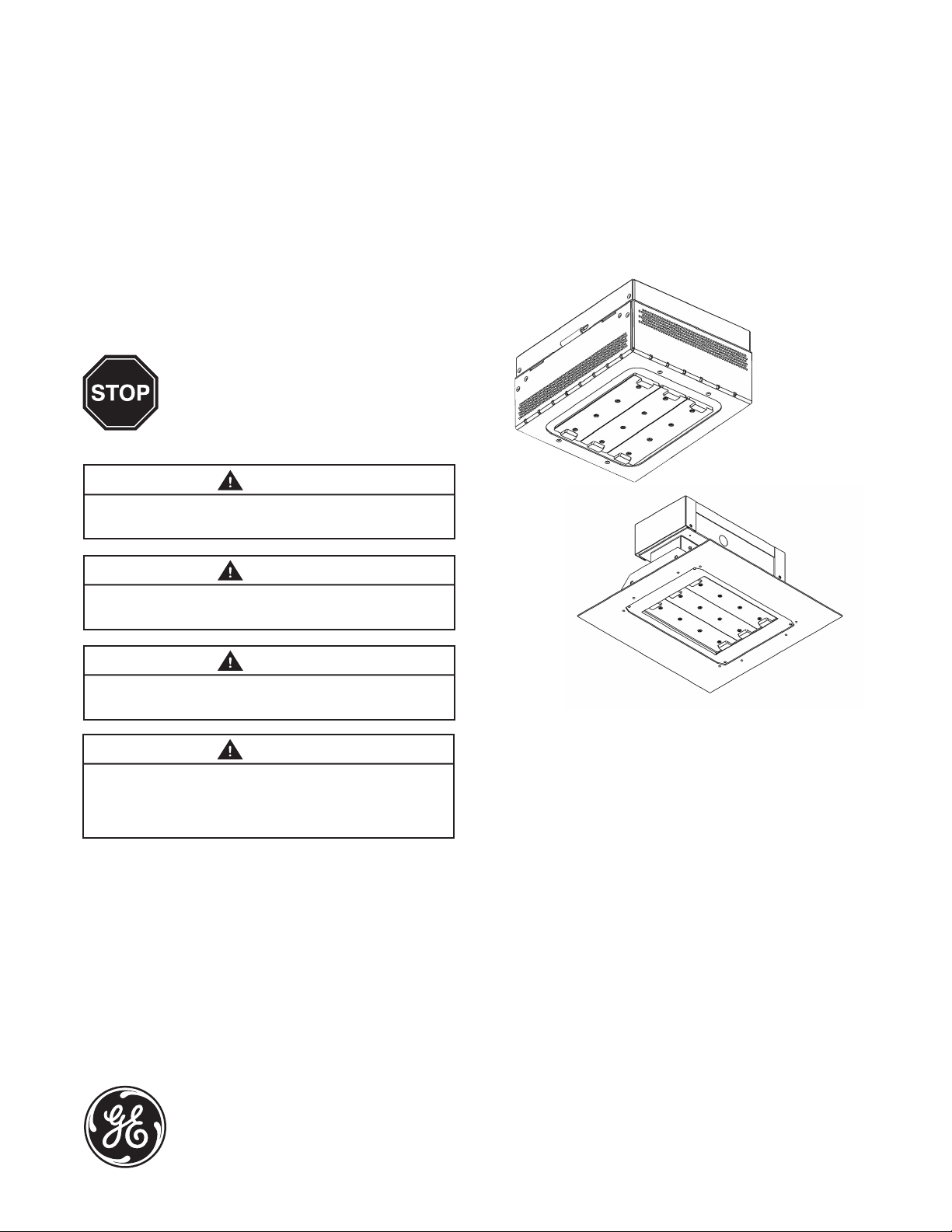
Surface Mount
Recessed
• This luminaire is designed for outdoor lighting service,
and should not be used in areas of limited ventilation,
or in high ambient temperatures.
• Best results will be obtained if installed and
maintained according to the following
recommendations.
• Luminaire is designed to operate in typical
temperatures at 25°C and to be mounted horizontally
with LEDs facing down, as shown.
SPECIFICATIONS
• Weight: Maximum weight 13.2 lbs. (6 kg)
• IP Rating: Wet Location (IP65 for optical)
imagination at work
Page 2
UNPACKING
1
• This luminaire has been properly packed so that no
parts should have been damaged during transit.
• Inspect to conrm.
• The mounting bracket is shipped in a separate box.
HANDLING
2
• Damage may occur if luminaire is improperly handled
outside of pack.
• Do not impact or stack luminaire after removal from
packaging.
MOUNTING
3
Surface Mount
WARNING
Risk of injury or damage. Unit will fall if not installed
properly. Follow installation instructions.
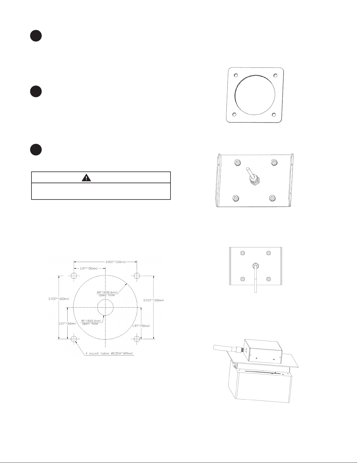
B. Liberally apply RTV sealant where the holes were
drilled and around the large center hole on both sides
of the gasket. Place the big gasket on the top of the
holes. (See Fig.4))
FIGURE 4
C. Place pre-installed plate bracket on the gasket.
(See Fig.5)
A. Pre-installation
1. Drill 4 3/8” mount holes for dimensions in ceiling to
mount xture. If the size of open hole of ceiling is less
than
to the
1”, then enlarge the open hole to 1”. Please refer
mounting template. (See Fig.3)
FIGURE 3
DRILL 3/8”
FIGURE 5
D. RTV caulk around the plate bracket and all fasteners
to ensure waterproong of luminaire. (See Fig.6)
FIGURE 6
E. Let one side of SJOW cable wire pass through hole
using a waterproof sleeve to connect to existing power
line in existing terminal box. Tighten the nut of
waterproof sleeve. (See Fig. 7)
2. Clean all areas that will be sealed.
FIGURE 7
Page 3
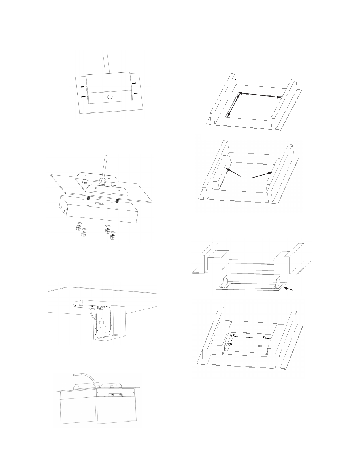
F. Tighten the screw (4-M4) to assemble junction box
with plate bracket. Torque reference 2.1ft-lbs
(2.9 N-m). (See Fig. 8)
FIGURE 13
G. From under the structure fasten 4pcs M8 nut lock
washer and washer to x mount box with ceiling
and plate bracket. Torque top and bottom bolts to
25 - 32 ft-lbs (34-43 N-m). (See Fig.9)
Recessed Installation
1. Cut a square hole on Ceiling. Additional studs may
be required to xed on ceiling rib.
Hole size: 12”x 12”/ 16” X 16”
Stud
FIGURE 9
H. Tilt the luminaire and insert it into the mount box
tting. Use 3M 314 waterproof connectors to connect
power cable from luminaire where Black is Line,
White is Neutral and green is ground to SJOW cable wire.
(See Fig.10, 11)
FIGURE 10, 11 & 12
I. Lift and push luminaire up to mount box.
Fasten 2 M4 to secure luminaire with mount box.
(Fig. 11 & Fig. 12)
2. Mount the light housing and secure to the studs.
The light housing mounting hole are sized for ¼”
diameter screw.
Light Housing
FIGURE 12
Page 4
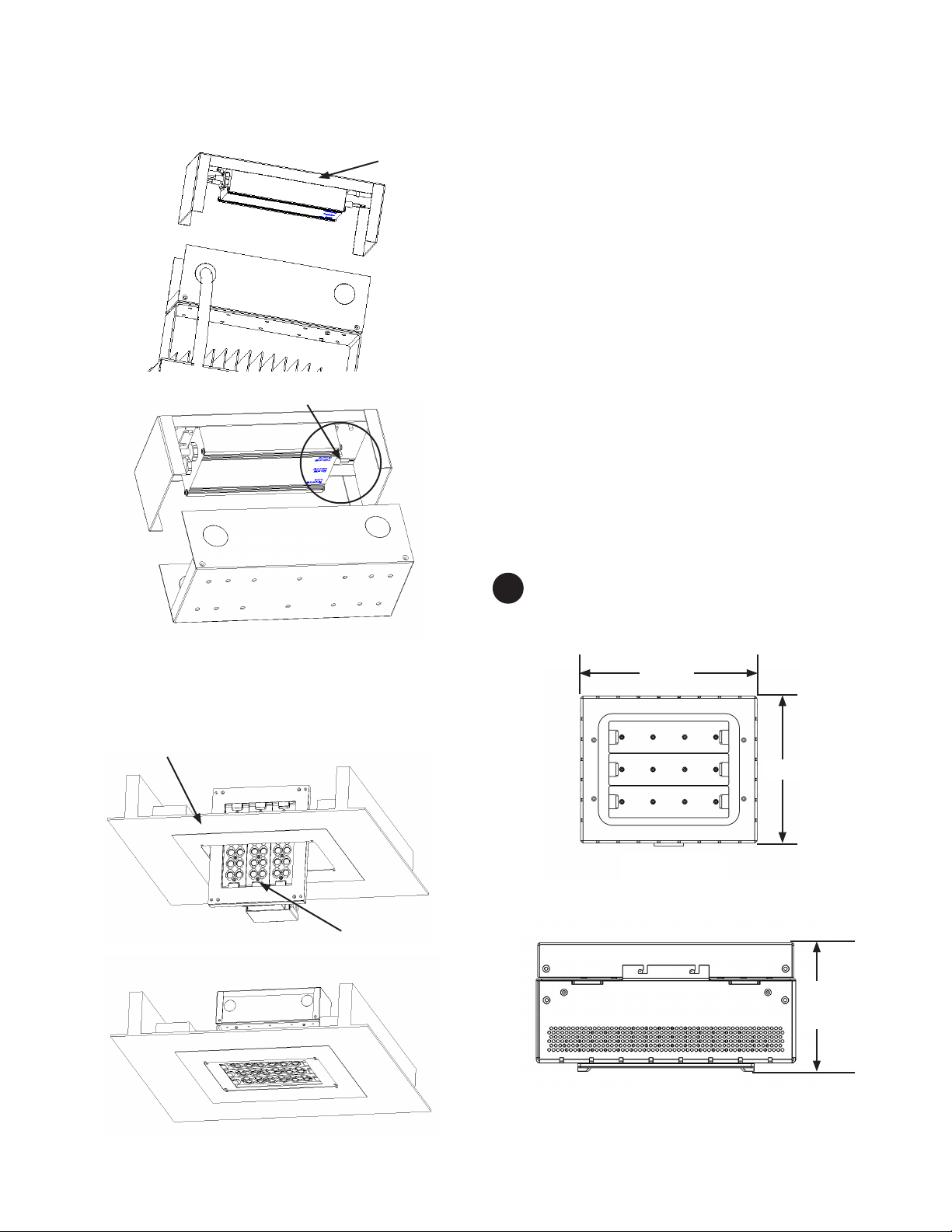
3. Open the junction Box cover. Make necessary supply
wiring connections to supplied power cords using
appropriate wire connectors.
Junction Box
Junction Box
Notes :
• This product must be installed in accordance with
applicable local, state, and national electrical codes
by a licensed person familiar with the construction
and operation of the product and hazards involved.
• This luminaire must adequately grounded for
protection against shock hazards and to assure
proper operation.
• Make sure all electrical power is turned o while
installing the xture.
• If the supply cord is damaged, it must be replaced by
the manufacturer or its service agent or a similar
qualied person in order to avoid a hazard.
• The structure of Installation of this lighting needs to
aord load of 16 pounds. To avoid Lamp fall.
• Lamps recommended installation height of 16 feet or
above.
4. Lift the luminaire up to the light housing. Assemble
luminaire and light housing using 4 pcs M4 screws
(provided).
Light Housing
Luminaire
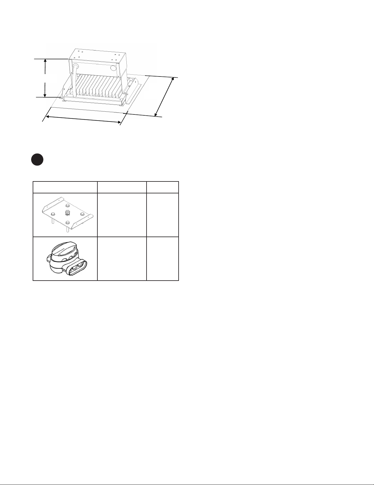
PRODUCT DIMENSIONS
4
Surface Mount
11.81 in.
BOTTOM VIEW
9.84 in.
5.75 in.
SIDE VIEW
Page 5
Recessed Installation
14” / 18”
7.1”
7.1 in.
11.1”
14” / 18”
14” / 18”
ACCESSORY COMPONENTS LIST
5
Surface Mount
Drawing Name Qty.
Plate bracket 1 pc
8.8”
8.8 in.
14” / 18”
3M Terminal 3 pcs
Page 6
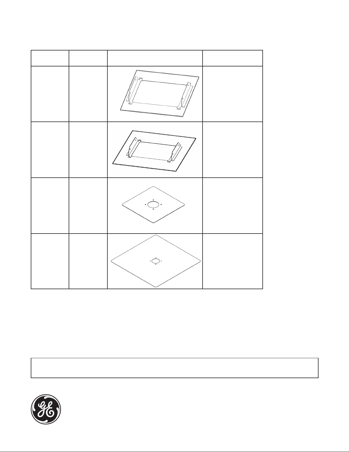
Recessed Installation
Light stands Accessories Type (Optional)
Spec (inches) Schematic diagram Accessories
Items
Accessories
12” 14 x 14 x 2 1/4” screws x 4
Light Housing X1
M4 screw 4 X 4 (incl)
Accessories
16” 18 x 18 x 2 1/4” screws x 4
Light Housing X1
M4 screw 4 X 4 (incl)
Accessories
16” 16 x 16 1/4” screws x 4
Eschutcheon Plate X1
M4 screw 4 X 4 (incl)
Accessories
32” 32 x 32 1/4” screws x 4
Eschutcheon Plate X1
M4 screw 4 X 4 (incl)
These instructions do not purport to cover all details or variations in equipment nor to provide for every possible contingency to be met in
connection with installation, operation or maintenance. Should further information be desired or should particular problems arise which are not
covered suciently for the purchaser’s purposes, the matter should be referred to GE Lighting.
GE Lighting • 1-888-MY-GE-LED (1 - 888 - 69 - 43 - 533) • www.gelighting.com
Evolve and the GE brand and logo are trademarks of the General Electric Company.
© 2013 GE Lighting. Information provided is subject to change without notice. All values are design or typical values when measured under laboratory conditions.
35-201578-212 (Rev 12/11/13)
English
Page 7

GE
Guide d’installation
Lighting
Luminaire de zone à DEL Evolve
Plafonnier, montage en surface et encastré (ECSA)
GEH-6020
™
ARRÊT
AVANT DE COMMENCER
Lisez attentivement toutes ces instructions.
Conservez ces instructions pour référence future.
AVERTISSEMENT
Risque de choc électrique. Déconnectez l’alimentation électrique
avant d’installer ou réparer ce produit.
AVERTISSEMENT
Danger de blessure et de dommage matériel. L’appareil tombera
au sol s’il est mal installé. Suivez les instructions d’installation.
ATTENTION
Danger de blessure. Lors de l’installation et de la réparation de cet
appareil, porter des lunettes et des gants de sécurité.
AVERTISSEMENT
Ce produit doit être installé conformément au code d’installation
applicable, par une personne connaissant bien la construction et
l’utilisation du produit, ainsi que les dangers qu’il comporte.
Cet appareil est conforme aux exigences de la partie 15 des règles de la
FCC. Son utilisation est sujette aux conditions suivantes : (1) cet appareil
ne doit pas causer d’interférences nuisibles; (2) cet appareil doit accepter
toutes les interférences reçues, y compris celles pouvant causer un fonctionnement indésirable. Ce DEFR de la classe [A] est conforme à la norme
NMB-003 du Canada.
Remarque : Cet appareil a été testé et reconnu conforme aux limites
établies pour les appareils numériques de classe A, selon la partie 15 des
règles de la FCC. Ces limites sont conçues pour assurer une protection raisonnable contre les interférences nuisibles dans un environnement commercial. Cet appareil génère, utilise et émet de l’énergie sous forme de
radiofréquences, de sorte que si son installation et son utilisation ne sont
pas conformes à la notice d’utilisation, il peut être la cause de parasites
nuisibles aux communications radio. L’utilisation de cet équipement dans
une zone résidentielle risque fort de causer des interférences nuisibles,
auquel cas l’utilisateur devra corriger le problème à ses propres frais.
Montage en surface
Montage encastré
• Ce luminaire a été conçu pour une utilisation à l’extérieur et
ne doit pas être employé sur un site mal ventilé ni dans un
endroit clos dont la température ambiante peut être élevée.
• Pour obtenir des performances optimales, il doit être
installé et entretenu conformément aux recommandations
suivantes.
• Ce luminaire a été conçu pour fonctionner sous des
températures typiques de 25 ºC. Il doit être installé à
l’horizontale, avec les lampes à DEL tournées vers le bas,
conformément à l’illustration.
SPÉCIFICATIONS
• Poids : Poids maximum 13,2 lb (6 kg)
• Classication IP : Sites humides (IP65 pour le module optique)
imagination at work
Page 8

DÉBALLAGE
1
• Ce luminaire a été soigneusement emballé pour qu’aucune
pièce ne subisse de dommages durant le transport.
• Procédez à une inspection pour vous en assurer.
• Le support de montage est livré dans une boîte séparée.
MANUTENTION
2
• Si le luminaire est incorrectement manipulé hors de son
emballage, il risque d’être endommagé.
• Lorsque le luminaire est sorti de son emballage, il ne doit
pas recevoir le moindre coup ni être empilé.
ASSEMBLAGE
3
Montage en surface
AVERTISSEMENT
Danger de blessure et de dommage matériel. L’appareil tombera
au sol s’il est mal installé. Suivez les instructions d’installation.
B. Appliquez une généreuse quantité de silicone résistant aux
variations de température aux endroits où des trous ont été
percés et autour du grand trou central sur les deux côtés de
la plaque d’étanchéité. Placez la plaque d’étanchéité sur les
trous (gure 4).
FIGURE 4
C. Placez la plaque d’appui préinstallée sur la plaque
d’étanchéité (gure 5).
A. Opérations préliminaires
1. Sur le plafond, percez 4 trous de montage d’un diamètre
de 3/8 po avec un espacement approprié pour installer
l’appareil d’éclairage. Si l’orice disponible dans le plafond
mesure moins de 1 po, agrandissez-le à 1 po. Référez-vous
au gabarit de montage (gure 3).
Trou débouchant
Trou débouchant
FIGURE 3
4 orices de montage, ø 9 mm
PERFORATION DE 3/8 PO
FIGURE 5
D. Appliquez du silicone résistant aux variations de tempéra-
ture sur la plaque d’appui et sur les attaches pour garantir
l’étanchéité du luminaire (gure 6).
FIGURE 6
E. Faites passer une extrémité du câble SJOW dans l’orice
avec l’aide d’un manchon étanche, an de connecter
l’alimentation électrique sur le boîtier de jonction. Serrez
l’écrou du manchon étanche (gure 7).
2. Nettoyez toutes les surfaces qui seront enduites de silicone.
FIGURE 7
Page 9

F. Serrez la vis (4-M4) pour assembler le boîtier de jonction
avec la plaque d’appui. Serrez avec un couple de 2,1 lb-pi
(2,9 Nm) (gure 8).
FIGURE 13
G. Par le dessous de la structure, installez 4 rondelles-freins
d’écrou et rondelles pour xer le boîtier de montage sur le
plafond et la plaque d’appui. Serrez les boulons du haut et
du bas au couple de 25-32 lb-pi (34-43 N.m) (gure 9).
Installation encastrée
1. Découpez un trou carré dans le plafond. Des traverses
supplémentaires peuvent être nécessaires dans la
charpente du plafond. Dimensions du trou : 12 po x 12 po /
16 po x 16 po.
Stud
FIGURE 9
H. Inclinez le luminaire et insérez-le dans le boîtier de montage.
Utilisez des connecteurs étanches 3M 314 pour connecter
le câble d’alimentation du luminaire (le l noir correspond à
la tension, le l blanc au neutre et le l vert à la terre) au l
SJOW (gures 10 et 11).
FIGURE 10, 11 & 12
I. Levez et enfoncez le luminaire dans le boîtier de montage.
Installez deux vis M4 pour faire tenir le luminaire sur la boîte
de montage (gures 11 et 12).
2. Montez le boîtier du luminaire et xez-le sur les traverses.
Les trous de montage du boîtier du luminaire ont été
prévus pour des vis de 3/4 po.
Boîtier du luminaire
FIGURE 12
Page 10

3. Ouvrez le couvercle du boîtier de jonction. Eectuez les
connexions nécessaires d’alimentation électrique sur les
ls électriques fournis avec des serre-ls appropriés.
Boîtier de
jonction
Boîtier de jonction
Remarques :
• Ce produit doit être installé conformément aux normes et
au code électrique en vigueur, par une personne qualiée
connaissant bien la construction et l’utilisation du produit,
ainsi que les dangers qu’il comporte.
• Ce luminaire doit être correctement mis à la terre an
d’orir une protection contre les risques d’électrocution et
pour garantir son bon fonctionnement.
• Lors de l’installation de cet appareil d’éclairage, assurezvous que l’électricité est entièrement coupée.
• Si le cordon d’alimentation est endommagé, il doit être
remplacé par le fabricant, par un agent ou par une personne qualiée, an d’éviter tout danger.
• La structure d’installation de cet appareil d’éclairage doit
pouvoir supporter un poids de 16 lb (7,5 kg) pour éviter une
chute de la lampe.
• Lampes recommandées pour une installation à une hauteur de 16 pieds et plus.
4. Soulevez le luminaire jusqu’au boîtier du luminaire. Fixez le
luminaire sur le boîtier avec l’aide de 4 vis M4 (incluses).
Boîtier du luminaire
Luminaire
DIMENSIONS DU PRODUIT
4
Montage en surface
11,81 po
VUE DU DESSOUS
9,84 po.
5,75 po
VUE LATÉRALE
Page 11

Installation encastrée
14” / 18”
7.1”
7,1 po
11.1”
14” / 18”
14 po / 18 po
LISTE D’ACCESSOIRES
5
Montage en surface
Schéma Nom Qté
Plaque d’appui 1
8.8”
8,8 po
14 po / 18 po
Connecteur 3M 3
Page 12

Installation encastrée
Accessoires de xation de lampadaire (facultatifs)
Spécications Schéma Éléments
(po) d’accessoires
Accessoires
12 po 14 x 14 x 2 Vis 1/4 po (4)
Boîtier de lampadaire (1)
Vis M4 (4 x 4) (incl.)
Accessoires
16 po 18 x 18 x 2 Vis 1/4 po (4)
Boîtier de lampadaire (1)
Vis M4 (4 x 4) (incl.)
Accessoires
16 po 16 x 16 Vis 1/4 po (4)
Platine (1)
Vis M4 (4 x 4) (incl.)
Accessoires
32 po 32 x 32 Vis 1/4 po (4)
Platine (1)
Vis M4 (4 x 4) (incl.)
Ces instructions n’ont pas pour but de couvrir tous les détails et toutes les variantes de l’équipement, ni de répondre à tous les impondérables possibles en relation
avec l’installation, le fonctionnement et l’entretien. Si vous désirez plus d’informations ou si des problèmes particuliers surviennent qui ne sont pas couverts susamment pour les besoins de l’acheteur, le sujet doit être soumis à GE Lighting.
GE Lighting • 1-888-MY-GE-LED (1 - 888 - 69 - 43 - 533) • www.gelighting.com
Evolve ainsi que la marque et le logo GE sont des marques commerciales déposées de la General Electric Company.
© 2013 GE Lighting. Les informations fournies ici sont susceptibles de changer sans préavis. Toutes les données sont des valeurs de conception ou caractéristiques lors de leur
mesure en conditions de laboratoire.
35-201578-212 (Rév 12/11/13)
Français
Page 13

GE
Guía de instalación
GEH-6020
Lighting
™
Luminaria LED de área Evolve
Luminaria de marquesina para montaje en supercie o empotrado (ECSA)
ANTES DE COMENZAR
Lea estas instrucciones de forma completa y
atenta.
Guarde estas instrucciones para su uso futuro.
ADVERTENCIA
Riesgo de choque eléctrico. Desconecte la alimentación eléctrica
antes de instalar o prestar servicio al producto.
ADVERTENCIA
Riesgo de lesiones o daños. La unidad se caerá si no se la instala
correctamente. Siga las instrucciones de instalación.
PRECAUCIÓN
Riesgo de lesiones. Use guantes y gafas de seguridad durante la
instalación y el servicio.
ADVERTENCIA
Este producto debe ser instalado, de acuerdo con el código de
instalación aplicable, por una persona familiarizada con la construcción y operación del producto y los riesgos asociados.
Este dispositivo cumple con la Parte 15 de las Reglas de la FCC. La operación
está sujeta a las dos condiciones siguientes: (1) este dispositivo no puede causar
interferencia perjudicial, y (2) este dispositivo debe aceptar cualquier interferencia
recibida, incluida la interferencia que pueda causar una operación no deseada.
Este Dispositivo de iluminación de radiofrecuencia (RFLD) de Clase [A] cumple con
la norma canadiense ICES-003. Ce DEFR de la classe [A] est conforme à la NMB-003
du Canada.
Montaje en supercie
Montaje empotrado
• Esta luminaria está diseñada para servicio de iluminación
en exteriores, y no debe ser usada en áreas con ventilación
limitada ni con temperaturas ambientes altas.
• Se obtendrán los mejores resultados si se la instala y se
realiza el mantenimiento de acuerdo con las siguientes
recomendaciones.
• La luminaria está diseñada para operar con temperaturas
normales de alrededor de 25 ºC y para ser montada en
posición horizontal con los LED apuntando hacia abajo,
como se muestra.
Nota: este equipo ha sido probado y se ha determinado que cumple con los límites
de un dispositivo digital Clase A, de conformidad con la Parte 15 de las Reglas de
la FCC. Estos límites están diseñados para proporcionar una protección razonable
contra la interferencia perjudicial cuando el equipo se opera en un entorno comercial. Este equipo genera, usa y puede irradiar energía de radiofrecuencia y, si no se
instala y usa de acuerdo con el manual de instrucciones, puede causar interferencia
perjudicial a las radiocomunicaciones. La operación de este equipo en un área
residencial puede causar interferencia perjudicial, en cuyo caso el usuario deberá
corregir la interferencia a su propia costa.
imagination at work
ESPECIFICACIONES
• Peso: máximo 13.2 lb (6 kg)
• Grado IP: entorno húmedo (IP65 para la óptica)
Page 14

DESEMBALAJE
1
• Esta luminaria fue embalada adecuadamente, de manera
que ninguna pieza resultara dañada durante su transporte.
• Examínela para conrmar que así sea.
• El soporte de montaje se envía en una caja separada.
MANEJO
2
• Pueden producirse daños si la luminaria es manejada incorrectamente una vez extraída del embalaje.
• No golpee ni apile las luminarias después de retirarlas del
embalaje.
MONTAJE
3
Montaje en supercie
ADVERTENCIA
Riesgo de lesiones o daños. La unidad se caerá si no se la instala
correctamente. Siga las instrucciones de instalación.
B. Aplique sellador RTV en cantidad abundante donde se per-
foraron agujeros y alrededor del agujero central grande en
ambos lados de la junta. Coloque la junta grande sobre los
agujeros (vea la Fig. 4).
FIGURA 4
C. Coloque el soporte de chapa pre-instalado sobre la junta
(vea la Fig. 5).
A. Pre-instalación
1. Perfore 4 agujeros de montaje de 3/8” en el cielorraso según
las dimensiones indicadas para el montaje del artefacto. Si
el tamaño del agujero abierto del cielorraso es menor de 1”,
agrándelo a 1”. Consulte la planilla de montaje (vea la Fig. 3).
AGUJERO ABIERTO
AGUJERO ABIERTO
FIGURA 3
4 AGUJEROS DE MONTAJE, Ø 0.354” (Ø 9.0 MM)
PERFORACIONES 3/8”
FIGURA 5
D. Aplique RTV alrededor del soporte de chapa y de todos
los sujetadores, a n de asegurar la hermeticidad de la
luminaria (vea la Fig. 6).
FIGURA 6
E. Haga pasar un lado del cable tipo SJOW a través del agu-
jero mediante un manguito hermético, para conectar a la
línea de alimentación eléctrica existente en la caja de conexiones existente. Apriete la tuerca del manguito hermético
(vea la Fig. 7).
2. Limpie todas las áreas que se van a sellar.
FIGURA 7
Page 15

F. Apriete los 4 tornillos M4 para unir la caja de conexiones
con el soporte de chapa. Par de apriete: 2.1 lb·pie (2.9 N·m)
(vea la Fig. 8).
FIGURA 13
G. Desde debajo de la estructura, instale 4 conjuntos de tuer-
ca, arandela de presión y arandela M8 para jar la caja de
montaje al cielorraso y el soporte de chapa. Aplique a los
pernos superiores e inferiores un par de apriete de 25 a 32
lb·pie (de 34 a 43 N·m) (vea la Fig. 9).
Instalación empotrada
1. Corte un agujero cuadrado en el cielorraso. Es posible
que se necesiten montantes adicionales para la jación al
reborde del cielorraso.
Tamaño del agujero: 12” x 12” / 16” x 16”
Montante
FIGURA 9
H. Incline la luminaria e insértela en las piezas de conexión
de la caja de montaje. Utilice conectores herméticos 314
de 3M para conectar el cable de alimentación eléctrica
de la luminaria (en el que el cable negro es Línea [vivo], el
cable blanco es Neutro y el cable verde es masa [tierra])
al cable tipo SJOW (vea las Fig. 10 y 11).
FIGURAS 10, 11 Y 12
I. Levante la luminaria hasta la caja de montaje. Instale dos
tornillos M4 para asegurar la luminaria a la caja de montaje (vea la Fig. 11 y la Fig. 12).
2. Monte el alojamiento de la luminaria y asegúrelo a los
montantes. Los agujeros de montaje del alojamiento de la
luminaria están dimensionados para tornillos de 1/4” de
diámetro.
Alojamiento de la
luminaria
FIGURA 12
Page 16

3. Abra la cubierta de la caja de conexiones. Haga las conexiones necesarias del cableado de alimentación a los
cordones de alimentación suministrados por medio de los
conectores para cable apropiados.
Caja de
conexiones
Caja de conexiones
Notas:
• Este producto debe ser instalado, de acuerdo con los códigos eléctricos locales, estatales/provinciales y nacionales
aplicables, por una persona autorizada y familiarizada
con la construcción y operación del producto y los riesgos
asociados.
• Esta luminaria debe tener una puesta a tierra adecuada
como protección contra los riesgos de choque eléctrico y
para asegurar una operación correcta.
• Asegúrese de que la alimentación eléctrica esté totalmente
desconectada al instalar el artefacto.
• Si el cordón de alimentación eléctrica está dañado, debe
ser reemplazado por el fabricante, su agente de servicio, o
una persona calicada similar, a n de evitar riesgos.
• La estructura de instalacion de esta luminaria debe
soportar una carga de 16 libras para evitar la caída de la
lámpara.
• La altura de instalación recomendada para estas lámparas
es 16 pies o mayor.
4. Levante la luminaria hasta el alojamiento. Monte la luminaria y el alojamiento por medio de 4 tornillos M4 (suministrados).
Alojamiento de la luminaria
Luminaria
DIMENSIONES DEL PRODUCTO
4
Montaje en supercie
11.81 pulg.
VISTA INFERIOR
9.84 pulg.
5.75 pulg.
VISTA LATERAL
Page 17

Instalación empotrada
14” / 18”
7.1”
7.1 pulg.
11.1”
14” / 18”
14 pulg. / 18 pulg.
LISTA DE COMPONENTES AUXILIARES
5
Montaje en supercie
Plano Nombre Cant.
Soporte de chapa 1
8.8”
8.8
pulg.
14 pulg. / 18 pulg.
Terminal 3M 3
Page 18

Instalación empotrada
Accesorios del tipo de soporte de luz (opcionales)
Especicación Diagrama esquemático Elementos de los
(pulgadas) accesorios
Accesorios
12 pulg. 14 x 14 x 2 Tornillo de 1/4” (cant.: 4)
Alojamiento de la luminaria (cant.: 1)
Tornillo M4 x 4 (cant.: 4)
(incl.)
Accesorios
16 pulg. 18 x 18 x 2 Tornillo de 1/4” (cant.: 4)
Alojamiento de la luminaria (cant.: 1)
Tornillo M4 x 4 (cant.: 4)
(incl.)
Accesorios
16 pulg. 16 x 16 Tornillo de 1/4” (cant.: 4)
Placa ornamental
(cant.: 1)
Tornillo M4 x 4 (cant.: 4)
(incl.)
Accesorios
32 pulg. 32 x 32 Tornillo de 1/4” (cant.: 4)
Placa ornamental
(cant.: 1)
Tornillo M4 x 4 (cant.: 4)
(incl.)
Estas instrucciones no pretenden cubrir todos los detalles o variaciones en los equipos, ni contemplar toda posible contingencia a encontrar en
relación con la instalación, operación o mantenimiento. Si se deseara información adicional o surgiera algún problema especíco que no esté
sucientemente tratado aquí para los propósitos del comprador, debe consultarse a GE Lighting.
GE Lighting • 1-888-MY-GE-LED (1 - 888 - 69 - 43 - 533) • www.gelighting.com
Evolve y la marca y logo GE son marcas registradas de General Electric Company.
© 2013 GE Lighting. La información suministrada está sujeta a cambios sin aviso previo. Todos los valores son valores típicos o de diseño,
medidos en condiciones de laboratorio.
35-201578-212 (Rev 12/11/13)
Español
 Loading...