

Page 1

GE Healthcare
eBike III basic
eBike III comfort
with and without NIBP
Service Manual
2018111-336 Revision B
Page 2

Page 3

Manual InforMatIon
• GE Medical Systems Information Technologies GmbH considers itself responsible for the eects on safety,reliability, and
performance of the equipment, only if:
- assembly operations, extensions, readjustments, modications, or repairs are carried out by ergoline GmbH or by
persons authorized by GE Medical Systems Information Technologies GmbH,
- the electrical installation of the relevant room complies with the applicable national and local requirements,
- and the instrument is used in accordance with the intended use and the instructions for use.
• This manual contains service information; operating instructions are provided in the operator’s manual of the
instrument.
• This manual is in conformity with the instrument at printing date.
• The Service Manual eBike III is valid for the following devices:
2017911-301 EBIKE III BASIC
2017911-303 EBIKE III BASIC WITH NIBP
2017911-305 EBIKE III COMFORT
2017911-307 EBIKE III COMFORT WITH NIBP
Software Version GF 1.x and optional with Module “NIBP“ and Supply and Service Items.
Manufacturer: Distributor:
ergoline GmbH GE Medical Systems Information Technologies, Inc
Lindenstraße 5 8200 West Tower Avenue
D-72475 Bitz Milwaukee, WI 53223 USA
Germany Tel. +1 414 355 5000 1 800 437 1171 (US only)
Tel.: +49 (0) 7431 98 94 - 0 1 800 668 0732 (Canada only)
Fax: +49 (0) 7431 98 94 - 128 Fax +1 414 355 3790
e-mail: info@ergoline.com
internet: http://www.ergoline.com
©Copyright 2016 General Electric Company. All rights reserved.
2018111-336 Rev. B eBike III basic / comfort - 3 -
Page 4
revIsIon HIstory
This manual is subject to the GE Medical Systems Information Technologies change order service.
The revision code, a letter that follows the document part number, changes with every update of the manual.
The initial version of the manual has the letter B.
Part No. Revision Code Date Comment
2018111-336 Rev A 2016-03 Engineering Release
2018111-336 Rev B 2016-04 Initial Release
- 4 - eBike III basic / comfort 2018111-336 Rev. B
Page 5

Contents
Manual Information . . . . . . . . . . . . . . . . . . . . . . . . . . . . . . . . 3
Revision History . . . . . . . . . . . . . . . . . . . . . . . . . . . . . . . . . . 4
Electrical Safety . . . . . . . . . . . . . . . . . . . . . . . . . . . . . . . . . 7
Leakage currents . . . . . . . . . . . . . . . . . . . . . . . . . . . . . . . . . . . . . . . . .7
Technical Safety Inspections and Inspections of the Measuring Systems . . . . . . . . . . . . . .7
eBike III basic / comfort . . . . . . . . . . . . . . . . . . . . . . . . . . . . . . 8
Very important service note . . . . . . . . . . . . . . . . . . . . . . . . . . . . . . . . . . .8
Preventive Maintenance . . . . . . . . . . . . . . . . . . . . . . . . . . . . . . . . . . . . . 8
Final checkout procedure / Functional test . . . . . . . . . . . . . . . . . . . . . . . . . . . . . . . . . . . . . . . . . . . . . .8
Electrical Safety . . . . . . . . . . . . . . . . . . . . . . . . . . . . . . . . . . . . . . . . . . . . . . . . . . . . . . . . . . . . . 10
Checkout procedure after repair . . . . . . . . . . . . . . . . . . . . . . . . . . . . . . . . 11
Test procedure “RPM / Load“ . . . . . . . . . . . . . . . . . . . . . . . . . . . . . . . . . . 15
Test procedure “Blood pressure (NIBP)“ . . . . . . . . . . . . . . . . . . . . . . . . . . . . . 17
Tools . . . . . . . . . . . . . . . . . . . . . . . . . . . . . . . . . . . . . . 18
Electronic modules / Assembly . . . . . . . . . . . . . . . . . . . . . . . . . . 19
Overview . . . . . . . . . . . . . . . . . . . . . . . . . . . . . . . . . . . . . . . . . . .19
Description of electronics and cabling . . . . . . . . . . . . . . . . . . . . . . . . . . . . . . . . . . . . . . . . . . . . . . . . 19
abbreviations (Electronic modules / PCBs) . . . . . . . . . . . . . . . . . . . . . . . . . . . . . . . . . . . . . . . . . . . . .19
Electronic carrier . . . . . . . . . . . . . . . . . . . . . . . . . . . . . . . . . . . . . . . . 20
Description . . . . . . . . . . . . . . . . . . . . . . . . . . . . . . . . . . . . . . . . . . . . . . . . . . . . . . . . . . . . . . . .20
Dismounting of the electronic assembly group . . . . . . . . . . . . . . . . . . . . . . . . . . . . . . . . . . . . . . . . . .20
Block diagrams bike ergometer electronics eBike III . . . . . . . . . . . . . . . . . . . . . . . 21
Wiring diagrams bike ergometer eBike III . . . . . . . . . . . . . . . . . . . . . . . . . . . . 25
Control units . . . . . . . . . . . . . . . . . . . . . . . . . . . . . . . . . . . . . . . . . 29
DTU - Control unit . . . . . . . . . . . . . . . . . . . . . . . . . . . . . . . . . . . . . . . . . . . . . . . . . . . . . . . . . . . .29
DTU - Patient display . . . . . . . . . . . . . . . . . . . . . . . . . . . . . . . . . . . . . . . . . . . . . . . . . . . . . . . . . .30
DTU - Connectors . . . . . . . . . . . . . . . . . . . . . . . . . . . . . . . . . . . . . . . . . . . . . . . . . . . . . . . . . . . .30
Load regulation and interface . . . . . . . . . . . . . . . . . . . . . . . . . . . . . . . . . 31
LIU - Load regulation and interface board . . . . . . . . . . . . . . . . . . . . . . . . . . . . . . . . . . . . . . . . . . . . .31
NIBP blood pressure unit . . . . . . . . . . . . . . . . . . . . . . . . . . . . . . . . . . . . 32
Assembly . . . . . . . . . . . . . . . . . . . . . . . . . . . . . . . . . . . . . . . . . . . . . . . . . . . . . . . . . . . . . . . . .32
Placement of pressure tubes (schematic) . . . . . . . . . . . . . . . . . . . . . . . . . . . . . . . . . . . . . . . . . . . . . . 33
Block diagram of cabling of the bloodpressure unit . . . . . . . . . . . . . . . . . . . . . . . . . . . . . . . . . . . . . . . . 33
BPU - Blood pressure board . . . . . . . . . . . . . . . . . . . . . . . . . . . . . . . . . . . . . . . . . . . . . . . . . . . . . .34
Miscellaneous modules . . . . . . . . . . . . . . . . . . . . . . . . . . . . . . . . . . . . . 35
SMU - saddle height motor . . . . . . . . . . . . . . . . . . . . . . . . . . . . . . . . . . . . . . . . . . . . . . . . . . . . . .35
Mechanical assembly . . . . . . . . . . . . . . . . . . . . . . . . . . . . . . 36
Controls and Indicators . . . . . . . . . . . . . . . . . . . . . . . . . . . . . . . . . . . .36
Mounting the Handlebar . . . . . . . . . . . . . . . . . . . . . . . . . . . . . . . . . . . . 37
Handlebar - Adjust xture (inclination) . . . . . . . . . . . . . . . . . . . . . . . . . . . . . . . . . . . . . . . . . . . . . . . 37
Handlebar - Dismounting / mounting . . . . . . . . . . . . . . . . . . . . . . . . . . . . . . . . . . . . . . . . . . . . . . . . 37
Remove Ergometer Housing . . . . . . . . . . . . . . . . . . . . . . . . . . . . . . . . . .39
Plastic screw seals (caps) . . . . . . . . . . . . . . . . . . . . . . . . . . . . . . . . . . . . . . . . . . . . . . . . . . . . . . . . 39
Dismounting the Handlebar pole housing . . . . . . . . . . . . . . . . . . . . . . . . . . . . . . . . . . . . . . . . . . . . . . 40
Dismount pedal cranks . . . . . . . . . . . . . . . . . . . . . . . . . . . . . . . . . . . . . 41
Remove housing of the eBike III basic . . . . . . . . . . . . . . . . . . . . . . . . . . . . . . . . . . . . . . . . . . . . . . . . 42
Remove housing of the eBike III comfort . . . . . . . . . . . . . . . . . . . . . . . . . . . . . . . . . . . . . . . . . . . . . .46
2018111-336 Rev. B eBike III basic / comfort - 5 -
Page 6

Saddle pillar exchange (eBike III basic) . . . . . . . . . . . . . . . . . . . . . . . . . . . . . . . . . . . . . . . . . . . . . . .50
Saddle motor (eBike III comfort) . . . . . . . . . . . . . . . . . . . . . . . . . . . . . . . . . . . . . . . . . . . . . . . . . . .51
Strain gauge module exchange . . . . . . . . . . . . . . . . . . . . . . . . . . . . . . . . . . . . . . . . . . . . . . . . . . . .53
RPM module exchange . . . . . . . . . . . . . . . . . . . . . . . . . . . . . . . . . . . . . . . . . . . . . . . . . . . . . . . . . 54
Load unit . . . . . . . . . . . . . . . . . . . . . . . . . . . . . . . . . . . . . . . . . . . 55
Assembly . . . . . . . . . . . . . . . . . . . . . . . . . . . . . . . . . . . . . . . . . . . . . . . . . . . . . . . . . . . . . . . . .55
Load unit replacement . . . . . . . . . . . . . . . . . . . . . . . . . . . . . . . . . . . . . . . . . . . . . . . . . . . . . . . . .55
Power switch replacement . . . . . . . . . . . . . . . . . . . . . . . . . . . . . . . . . . . 56
Power supply unit replacement . . . . . . . . . . . . . . . . . . . . . . . . . . . . . . . . . 57
Remove Control unit . . . . . . . . . . . . . . . . . . . . . . . . . . . . . . . . . . . . . . 58
Software Control terminal . . . . . . . . . . . . . . . . . . . . . . . . . . . 60
Turning the System On . . . . . . . . . . . . . . . . . . . . . . . . . . . . . . . . . . . . . 60
Settings Control Terminal . . . . . . . . . . . . . . . . . . . . . . . . . . . . . . . . . . .60
Service menu . . . . . . . . . . . . . . . . . . . . . . . . . . . . . . . . . . . . . . . . .61
Contrast . . . . . . . . . . . . . . . . . . . . . . . . . . . . . . . . . . . . . . . . . . . . . . . . . . . . . . . . . . . . . . . . . . 62
ECG Type . . . . . . . . . . . . . . . . . . . . . . . . . . . . . . . . . . . . . . . . . . . . . . . . . . . . . . . . . . . . . . . . . . 62
NIBP Beep . . . . . . . . . . . . . . . . . . . . . . . . . . . . . . . . . . . . . . . . . . . . . . . . . . . . . . . . . . . . . . . . . 63
NIBP mmHg / kPa . . . . . . . . . . . . . . . . . . . . . . . . . . . . . . . . . . . . . . . . . . . . . . . . . . . . . . . . . . . .63
Dynamic Load Cal. . . . . . . . . . . . . . . . . . . . . . . . . . . . . . . . . . . . . . . . . . . . . . . . . . . . . . . . . . . . . 64
Software Update . . . . . . . . . . . . . . . . . . . . . . . . . . . . . . . . . . . . . . . . . . . . . . . . . . . . . . . . . . . . . 64
Baudrate 8N2 . . . . . . . . . . . . . . . . . . . . . . . . . . . . . . . . . . . . . . . . . . . . . . . . . . . . . . . . . . . . . . . 64
Saddle Calibration . . . . . . . . . . . . . . . . . . . . . . . . . . . . . . . . . . . . . . . . . . . . . . . . . . . . . . . . . . . . 64
Manual Load . . . . . . . . . . . . . . . . . . . . . . . . . . . . . . . . . . . . . . . . . . . . . . . . . . . . . . . . . . . . . . . 66
System Cong. . . . . . . . . . . . . . . . . . . . . . . . . . . . . . . . . . . . . . . . . . . . . . . . . . . . . . . . . . . . . . . 66
Error log . . . . . . . . . . . . . . . . . . . . . . . . . . . . . . . . . . . . . . . . . . . . . . . . . . . . . . . . . . . . . . . . . . 67
NIBP Test / NIBP Calibration . . . . . . . . . . . . . . . . . . . . . . . . . . . . . . . . . . . . . . . . . . . . . . . . . . . . . . 68
Analog Calibration. . . . . . . . . . . . . . . . . . . . . . . . . . . . . . . . . . . . . . . . . . . . . . . . . . . . . . . . . . . . 68
Alignment / Calibration . . . . . . . . . . . . . . . . . . . . . . . . . . . . . 72
Dynamic Load Calibration . . . . . . . . . . . . . . . . . . . . . . . . . . . . . . . . . . .72
Calibration of Blood pressure unit . . . . . . . . . . . . . . . . . . . . . . . . . . . . . . .75
NIBP Test . . . . . . . . . . . . . . . . . . . . . . . . . . . . . . . . . . . . . . . . . . . . . . . . . . . . . . . . . . . . . . . . .76
NIBP Calibration . . . . . . . . . . . . . . . . . . . . . . . . . . . . . . . . . . . . . . . . . . . . . . . . . . . . . . . . . . . . .77
Software update . . . . . . . . . . . . . . . . . . . . . . . . . . . . . . . . 78
Connectivity and installation eBike III to GE ECG devices . . . . . . . . . . . . . 81
eBike III to CASE . . . . . . . . . . . . . . . . . . . . . . . . . . . . . . . . . . . . . . . . 81
eBike III to CARDIOSOFT / CS . . . . . . . . . . . . . . . . . . . . . . . . . . . . . . . . . . 83
USB interface / driver installation . . . . . . . . . . . . . . . . . . . . . . . . . . . . . . . . . . . . . . . . . . . . . . . . . .83
eBike III to MAC 2000 . . . . . . . . . . . . . . . . . . . . . . . . . . . . . . . . . . . . . 87
eBike III to MAC 5500 (MAC 5000 ST) . . . . . . . . . . . . . . . . . . . . . . . . . . . . . 89
Installation of ther COM - Interface extension. . . . . . . . . . . . . . . . . . . . . . . . . . . . . . . . . . . . . . . . . . . 90
Addendum . . . . . . . . . . . . . . . . . . . . . . . . . . . . . . . . . . . 94
Errorcodes Software eBike III . . . . . . . . . . . . . . . . . . . . . . . . . . . . . . . . . . 94
Error code bits DTU (Control terminal PCB) . . . . . . . . . . . . . . . . . . . . . . . . . . . . . . . . . . . . . . . . . . . . .94
Error code bits LIU (Load regulation and interface PCB) . . . . . . . . . . . . . . . . . . . . . . . . . . . . . . . . . . . . . 95
Error code bits SMU (Saddle-Motor PCB) . . . . . . . . . . . . . . . . . . . . . . . . . . . . . . . . . . . . . . . . . . . . . . 96
Error code bits BPU (Blood pressure module) . . . . . . . . . . . . . . . . . . . . . . . . . . . . . . . . . . . . . . . . . . . . 97
Error code bits COM (External Analog interface module) . . . . . . . . . . . . . . . . . . . . . . . . . . . . . . . . . . . .98
Technical Specications eBike III basic / comfort . . . . . . . . . . . . . . . . . . . . . . . 121
Technical Specications eBike III Blood pressure module . . . . . . . . . . . . . . . . . . . 123
- 6 - eBike III basic / comfort 2018111-336 Rev. B
Page 7

eleCtrICal safety
leakage Currents
MeasurIng equIpMent
The measuring equipment used for the electrical safety
tests must be inspected and calibrated at regular intervals
(refer to manufacturer of measuring equipment).
The measurement results must be documented.
eBIke III BasIC / CoMfort
The eBike III basic/comfort ergometers are protection
class II equipment (no connection to protective ground).
The necessary electrical safety tests for these devices
together with the limit values are listed in the
chapter titled “eBike III basic/comfort - Preventive
maintenance“.
teCHnICal safety InspeCtIons and
nspeCtIons of tHe MeasurIng systeMs
I
The load unit is recommended to be inspected to the
approved regional standards at intervals of 2 years by a
GE Medical Systems Information Technologies authorized
service technician, and calibrated or repaired if necessary.
Calibration instructions for the NIBP module can be found
in this Service manual. Follow these instructions to display
the BP values with the test setup according to
EN 1060-1 and EN1060-3 or appropriate regional standard.
Warning
• Equipment Damage •
• The regulations about handling ESD sensitive components
must be observed.
Warning
• Patient Hazard, Equipment Damage
• EN 62353 and/or IEC 60601-1 requirements must be
satised during repair, modications and inspections of
medical electrical equipment.
• To ensure that equipment functions faultlessly and
without presenting any hazard after service interventions,
it must be subjected to the test procedures stipulated for
the dierent device categories.
• A device is considered to be unsafe, when:
- it cannot be repaired
- the user does not wish to have the device repaired.
In this case, the operator must be informed in
writing of the hazard presented by the device.
The same remark must be annotated on the
service report and on the service invoice..
The measurement results must be documented.
Warning
• Patient Hazard, Equipment Damage
• Use original spare parts only.
• For information about product changes, refer to the
manufacturer’s original documentation only.
• Observe the fuses’ original ratings, characteristics and
Ampere interrupting capacity.
• Parts of the device that ensure its safe operation must be
neither damaged nor obviously unsuitable. This applies to
insulation and insulating components in particular.
• Power cords must be visually inspected for signs of
damage before connecting them to the power line.
2018111-336 Rev. B eBike III basic / comfort - 7 -
Page 8

eBIke III BasIC / CoMfort
very IMportant servICe note
Warning
• Hazard, Equipment Damage
• When work at the bottom of the eBike III is required (e.g. access to electronic moduls, exchange
of load unit or installation of COM module) the eBike III should be carefully placed on one side
by grabbing it at the handlebar and the saddle.
• DO NOT tilt the eBike III forward to stand on the handlebar - this is an unsecure and instable
position!
preventIve MaIntenanCe
Note
• eBike III basic / comfort is a protection class II device (no connection to protective ground).
• Preventive maintenance is recommended to be performed every 2 years.
fInal CHeCkout proCedure / funCtIonal test
1. Check the setup for stability, adjust with leveling device if required.
Expected result: No instability Pass/Fail
2. Visually inspect the device:
- inspect cables / power cord
Expected result: No damage or wear detected Pass/Fail
- 8 - eBike III basic / comfort 2018111-336 Rev. B
Page 9

3. Check cranks and pedals:
- pedals have no signs for damage / wear
- pedals securely xed on cranks
- crank screws securely xed (torque 40 Nm ± 2 Nm) on axis
Expected result: Cranks and pedals OK Pass/Fail
eBike III basic
- Check bellow on saddle for damage / wear / cracks
- Check handlebar adjustment (angle)
- Check saddle height adjustment
- Check that the clamping levers (saddle [height] and handlebar [angle] adjustment) are tight.
Grease the thread of the saddle clamping lever.
(Use of an universal high-performance lubricant such as OKS 470 is recommended.)
eBike III comfort
- Check handlebar adjustment (angle)
- Check that the clamping lever is tight.
- Check electrical saddle adjustment: adjust minimum and maximum saddle height;
then return saddle to mid-level
- Check correct indication of saddle height display
- Check that the clamping lever for handlebar adjustment (angle) is tight
Expected result: Adjustments work and levers are tight, thread properly greased Pass/Fail
4. Using the power cord, connect the device to the mains power line and place the power switch in the ON position
Wait for self test to end:
- check LCD for error messages (refer to „Turning the System On“ on page 60)
- check the software version in the service menu for correct version GF 1.x
(refer to „Software update“ on page 78)
- check the “error log le“ in service menu (refer to „Error log“ on page 67)
Expected result: Device powers on without errors, FW is correct version, no errors logged Pass/Fail
5. Check speed indication (rpm) is displayed on LCD and the additional speed indication on the patient display.
Check noise level of idling drive unit (for example, for grinding noises or noise from the bearing)
Expected result: Speed displayed on both displays and no noticeable noise Pass/Fail
6. Units with NIBP module:
- Check cu tubing and tubing connections, microphone connectors
- Check blood pressure measurement on test subject at rest (refer to the „eBike III operators manual“)
- Check blood pressure readings are displayed on LCD
Expected result: BP values are displayed and in proper range Pass/Fail
7. Set manual load (see „Manual Load“ on page 66), change load (for example, 50 W, 100 W)
- Check load level and load indication
Expected result: Load is set and changes as expected Pass/Fail
8. If ergometer is remote controlled from ECG recorder or PC-ECG system:
- Check connecting cable
- Check load control via ECG recorder or PC ECG system
- Check remote start if applicable
Expected result: Ergometer can be controlled by external unit Pass/Fail
2018111-336 Rev. B eBike III basic / comfort - 9 -
Page 10

eleCtrICal safety
Perform electrical safety checks when indicated - current leakage test results meet requirements.
All indicated electrical safety checks require a pass/fail indication for steps performed.
Record the measurement values in your debrief.
Step Condition
(1)
UUT - ON
(2)
Result Leakage
Current limits
Earth Leakage Current
1. Forward Polarity N/A
2. Neutral open, Forward Polarity N/A
3. Neutral open, Reverse Polarity N/A
4. Reverse Polarity N/A
Enclosure Leakage Current
1. Forward Polarity NC __________ μA Pass/Fail 100 μA
2. Neutral open, Forward Polarity SFC __________ μA Pass/Fail 500 μA
3. Ground open, Forward Polarity N/A
4. Ground open, Reverse Polarity N/A
5. Neutral open, Reverse Polarity SFC __________ μA Pass/Fail 500 μA
6. Reverse Polarity NC __________ μA Pass/Fail 100 μA
Patient Leakage Current to Ground (3)
1. Forward Polarity NC __________ μA Pass/Fail 100 μA
2. Neutral open, Forward Polarity SFC __________ μA Pass/Fail 5000 μA
3. Ground open, Forward Polarity N/A
4. Ground open, Reverse Polarity N/A
5. Neutral open, Reverse Polarity SFC __________ μA Pass/Fail 5000 μA
6. Reverse Polarity NC __________ μA Pass/Fail 100 μA
Ground Continuity Resistance
1. AC mains power cord ground prong to
exposed metal surface (ground lug)
(1) NC = Normal Condition
SFC = Single Fault Condition
N/A = Not Applicable
(2) UUT = Unit Under Test
(3) Test applies for eBike III with blood pressure unit only - measuring point is the microphone connector
N/A
- 10 - eBike III basic / comfort 2018111-336 Rev. B
Page 11

CHeCkout proCedure after repaIr
After replacing a FRU or performing certain tasks, it is necessary to also inspect the unit and perform a series of checks to
ensure the unit is functioning properly. The following tables identify the inspections and checkout procedures to perform.
To use the tables, locate the relevant FRU or task in the rst column and note the required checkout procedure(s) for the
item(s). Then locate the corresponding instructions in the sections following the tables.
fru repaIrs (exCHange)
FRU P/N Functional Checkout Procedure
Plastic cover parts 2018111-300
Details
1,2,3,5,6,24 42
Electrical
safety checks
2018111-303
2018111-304
2018111-326
2018111-327
2018111-328
Saddle 2018111-022 1,11,12,15,16
Saddle clamp lever 2018111-148 1,11,12,15,16
Saddle tube 2018111-144
1,2,3,5,6,11,12,1718,19,20 42
2018111-310
Saddle guidance tube 2018111-332 1,2,3,5,6,12,17,18,19,20,24,40 42
Saddle motor 2018111-337 1,2,3,5,6,8,10,12,1718,19,20,24,40 42
Leg leveler(s) 2018111-021 1,23,24
Wheel set(s) 2018111-311 1,7,23,24
Pedal(s) / crank(s) 2018111-301
1,28,41
2018111-302
Handle bar 2018111-324 1,13,14
Handle bar clamp lever 2018111-322 1,13,14
Drive unit 2018111-306
1,2,3,8,9,10,21,22, 24,27,28,29,41 42
2018111-307
Strain gauge module 2018111-308 1,2,3,8,9,10,21,22, 24,27,28,29,39,41 42
RPM sensor 2018111-309 1,2,3,8,9,10,21,22, 24,27,28,29,39,41 42
Power supply 2018111-152 1,2,3,5,6,8,10,22, 24,27,28,29 42
2018111-336 Rev. B eBike III basic / comfort - 11 -
Page 12

FRU P/N Functional Checkout Procedure
Details
Electrical
safety checks
Power switch 2018111-305
1,2,3,5,6,8,10, 24,27,28,29 42
2018111-339
LIU (PCB) 2018111-312 1,2,3,8,9,10,21,22,
24,25,26,27,28,29,35,39
SMU (PCB) 2018111-314 1,2,3,8,9,10,21,22,
24,25,26,27,28,29,35,40
Blood pressure
components
2018111-313
2018111-315
1,2,3,8,9,10,21,22, 24,26,30,31,32,33,
34,35,36,37,38
42
42
42
2018111-316
2018111-317
2018111-318
Terminal cuff connector 2018111-323 1,2,3,4,8,10, 24,26,32,33,34,36,37,38 42
Control terminal w/o NIBP 2018111-321 1,4,8,21,22, 24,25,26,27,29,35 42
Control terminal with NIBP 2018111-320 1,4,8,21,22, 24,25,26,27,29,30,31,32,
33,34,35,36,37,38
42
non fru repaIrs
Repair Functional Checkout Procedure
Details
Software update 4,21,22, 24,26,27,30,32,33,34
Load calibration (recommended every 2 years) 1,2,3,21,22, 24,26,27,39
Electrical safety checkout (recommended every 2 years) 1,2,3,4,5,6,21,22,24,26 42
Electrical
safety checks
- 12 - eBike III basic / comfort 2018111-336 Rev. B
Page 13

funCtIonal CHeCkout proCedure detaIls
Visual / functional checks
1. External surfaces passed inspection? pass/fail
2. Plastic cover screws complete and xed? pass/fail
3. Plastic caps on housing screws complete? pass/fail
4. Terminal foil, LCD and LED passed inspection? pass/fail
5. AC Power cord passed inspection? pass/fail
6. AC power cord strain relief mounted and cable secured pass/fail
7. Casters passed inspection? pass/fail
8. All board connectors and cable connectors connected and secured? pass/fail
9. All PCBs xed with screws on electronic carrier? pass/fail
10. All harnesses‘ and internal wiring has been secured? pass/fail
11. Bellow on saddle passed inspection? pass/fail
12. Saddle xture on saddle tube passed inspection? pass/fail
13. Handlebar adjustment (angle) passed inspection?
(refer to „Handlebar - Adjust xture (inclination)“ on page 37) pass/fail
14. Clamping lever handlebar angle adjustment passed inspection? pass/fail
15. eBike III basic only: Mechanical saddle height adjustment passed inspection? pass/fail
16. eBike III basic only:Clamping lever saddle height passed inspection
(tight; thread of lever is greased)? pass/fail
17. eBike III comfort only: Saddle motor keys at terminal functional? pass/fail
18. eBike III comfort only: Electrical saddle adjustment passed inspection? pass/fail
19. eBike III comfort only: Check correct indication of saddle height display pass/fail
20. eBike III comfort only: Check if saddle tube moves tightly and without any mechanical wobble
in saddle tube guidance. pass/fail
21. Check software (rmware) is at correct version GF 1.x
(refer to „Software update“ on page 78) pass/fail
22. Check and clear the “error log le“ in service menu
(refer to „Error log“ on page 67) pass/fail
23. Check stable position on oor, check leveler adjustment pass/fail
Operational Checks
24. Power-up self-test passed (no error messages on LCD)? pass/fail
25. LCD contrast ok?
(refer to „Contrast“ on page 62) pass/fail
26. eBike successfully communicates with ECG device?
(refer to „Connectivity and installation eBike III to GE ECG devices“ on page 81) pass/fail
27. Check load level and load indication on LCD pass/fail
28. Set manual load (see „Manual Load“ on page 66),
change load (for example, 50 W, 100 W)
Check noise level of idling drive unit (for example, for grinding noises or noise from the bearing) pass/fail
29. Check speed indication (rpm) displayed on LCD and the additional speed indication
on the patient display. pass/fail
30. Blood pressure measurement successfully initiated by ECG device? pass/fail
31. Blood pressure values successfully communicated to ECG device pass/fail
32. Check cu tubing and tubing connections, microphone connectors pass/fail
33. Check blood pressure measurement on test subject at rest pass/fail
34. Check blood pressure readings on LCD pass/fail
Tests and Calibration Checks
35. System conguration and settings correct?
(refer to „System Cong.“ on page 66) pass/fail
36. NIBP test successfully passed?
(refer to „NIBP Test“ on page 76) pass/fail
37. NIBP calibration successfully performed?
(refer to „NIBP Calibration“ on page 77) pass/fail
2018111-336 Rev. B eBike III basic / comfort - 13 -
Page 14

38. Check and clear the “NIBP error log le“ in service menu
(refer to „Error log“ on page 67) pass/fail
39. Dynamic load calibration with test bench successfully performed?
(refer to „Dynamic Load Calibration“ on page 72) pass/fail
40. Electrical saddle adjustment: adjust minimum and maximum saddle height
(refer to „Saddle Calibration“ on page 64) pass/fail
41. Check torque values for screws pass/fail
Electrical Safety Checks
42. Current leakage and ground continuity test results meet requirements?
Perform electrical safety checks when indicated (refer to „Electrical Safety“ on page 10).
All indicated electrical safetychecks require a pass/fail indication for steps performed.
Record the measurement values. pass/fail
- 14 - eBike III basic / comfort 2018111-336 Rev. B
Page 15
test proCedure “rpM / load“
Note
• Unless regulatory requirements of the country dene a dierent test procedure or test intervall, it is recommended to perform the
test “RPM / load“ at least every 2 years.
Note
• An external calibration device for dynamic load testing is needed to perfom the following test procedures
(“ergoline ergotest 550“ - order direct from Ergoline P/N 705890) or equivalent device.
• Please refer to the operator manual of the used calibration device.
test preparatIon
1. Dismount BOTH (!) pedal cranks of the eBike III - see “Dismount pedal cranks“ under section „Dismount pedal cranks“
on page 41.
2. Follow the operator manual from the manufacture of calibration device being used to connect the calibration device
with the axis of the eBike III.
3. If supported by the calibration device, connect the eBike III interface (RS-232 or USB) with the calibration device.
4. Connect the calibration device to the PC / notebook setup containing the software and conguration to work with the
device.“
5. Start the test software of the calibration device.
rpM test protoCol
1. Apply a load of 100 W to the eBike III
(-either by command of the test software or manually on the eBike III (see „Manual Load“ on page 66).
2. Perform the following RPM tests step by step. Note the results in the table or use the printed protocol of the
calibration device to document the test.
Step Target RPM Actual RPM Deviation max. Pass / Fail
#1 30 ± 1 rpm
#2 40 ± 1 rpm
#3 50 ± 1 rpm
#4 100 ± 1 rpm
#5 120 ± 1 rpm
2018111-336 Rev. B eBike III basic / comfort - 15 -
Page 16

load test protoCol
1. Perform the load test (RPM is set by the calibration device / load of the eBike III is set either by command of the test
software or manually on the eBike III -see „Manual Load“ on page 66) step by step.
2. The actual load is measured and displayed by the calibration device software. Note the results in the table or use the
printed protocol of the calibration device to document the test.
Step RPM set Target Load Actual Load Deviation max. Pass / Fail
#1 40 25 ± 3 Watt
#2 40 50 ± 3 Watt
#3 40 100 ± 5 Watt
#4 70 200 ± 10 Watt
#5 90 300 ± 15 Watt
#6 100 500 ± 25 Watt
- 16 - eBike III basic / comfort 2018111-336 Rev. B
Page 17
test proCedure “Blood pressure (nIBp)“
Note
• Unless regulatory requirements of the country dene a dierent test procedure or test interval, it is recommended to perform the
test “Blood pressure (NIBP)“ at least every 2 years.
Note
• A calibrated NIBP measure instrument set is needed to perfom the following test procedures.
• Please refer to the operator manual of the used device.
test preparatIon
1. Power eBike III on and enter service menu / NIBP test (-see „Calibration of Blood pressure unit“ on page 75).
2. Connect the calibration equipment with the eBike III cu connector.
leak-tIgHtness test
1. Use the connected test equipment to apply the target pressure (see table below) to the eBike III cu connector, wait
until the pressure in the system has stabilized (approx. 5 sec).
2. After 1 min check the actual pressure and note the pressure drop in the table
Step Target Pressure Actual pressure drop Pressure drop max. Pass / Fail
#1 50 mmHg mmHg / min < 6 mmHg / min
#2 300 mmHg mmHg / min < 6 mmHg / min
aCCuraCy test
1. Use the connected test equipment to apply the target pressure (see table below) to the eBike III cu connector, wait
until the pressure in the system has stabilized (approx. 5 sec).
2. Check the actual pressure displayed on the eBike III display and note the value in the table.
Step Target pressure Displayed pressure (eBike III) Deviation max. Pass / Fail
#1 0 ± 3 mmHg
#2 50 ± 3 mmHg
#3 100 ± 3 mmHg
#4 150 ± 3 mmHg
#5 200 ± 3 mmHg
#6 250 ± 3 mmHg
#7 300 ± 3 mmHg
2018111-336 Rev. B eBike III basic / comfort - 17 -
Page 18

tools
The following tools (metric) are recommended to disassemble the eBike III devices:
Flat bladed screwdrivers: Allan keys:
1 pc. 1.0 x 0.18 mm 1 pc. 2.5 mm straight and elbow
1 pc. 4.5 x 0.8 mm 1 pc. 3 mm straight and elbow
1 pc. 4 mm straight and elbow
Philips screwdrivers: 1 pc. 5 mm straight and elbow
1 pc. PH 2
1 pc. PH 3 1 pc. 8 mm straight and elbow
1 pc. extension for Allen key 8 mm (drive unit exchange)
1 pc. 6 mm straight and elbow
Fork wrenches: Socket wrenches:
1 pc. 10 mm 1 pc. 10 mm
1 pc. 13 mm 1 pc. 13 mm
1 pc. 14 mm 1 pc. 14 mm
1 pc. 17 mm 1 pc TORX T30
1 pc. 19 mm
Pliers
1 pc. side cutter
1 pc. flat nose pliers
Special tools
1 pc. crank extractor (P/N 2005737-001)
1 pc. round pin, max. 3 mm, minimum length 15 mm
1 pc torque wrench (10 - 100 Nm)
1 pc. calibrated NIBP measurement instrument set
1 pc. external calibration device for dynamic load testing
(“ergoline ergotest 550“ - order direct from Ergoline P/N 705890) or equivalent device
- 18 - eBike III basic / comfort 2018111-336 Rev. B
Page 19

eleCtronIC Modules / asseMBly
overvIew
desCrIptIon of eleCtronICs and CaBlIng
The electronics of the eBike III are based on a modular
concept.
Each module has its own processor with appropriate
software.
To communicate between dierent modules, the CAN bus
is used, which is a stable and standardized protocol that is
used in the automotive industry.
The connection between dierent modules is made by
direct adaptation of the dierent PCBs or by use of
standard shielded CAT-5 patch cables.
The direct connectors and cables carry the power lines
(24 volt) and the CAN bus signal lines.
pcb direct connector SyStem
aBBrevIatIons (eleCtronIC Modules / pCBs)
DTU Display terminal unit
LIU Load regulation and interface unit
BPU Bloodpressure unit
SMU Saddle motor unit
(also used as handlebar motor unit))
DMS Torque sensor
LCD Display Standard connecting cablel (cat-5 patch cable, Shielded)
2018111-336 Rev. B eBike III basic / comfort - 19 -
Page 20
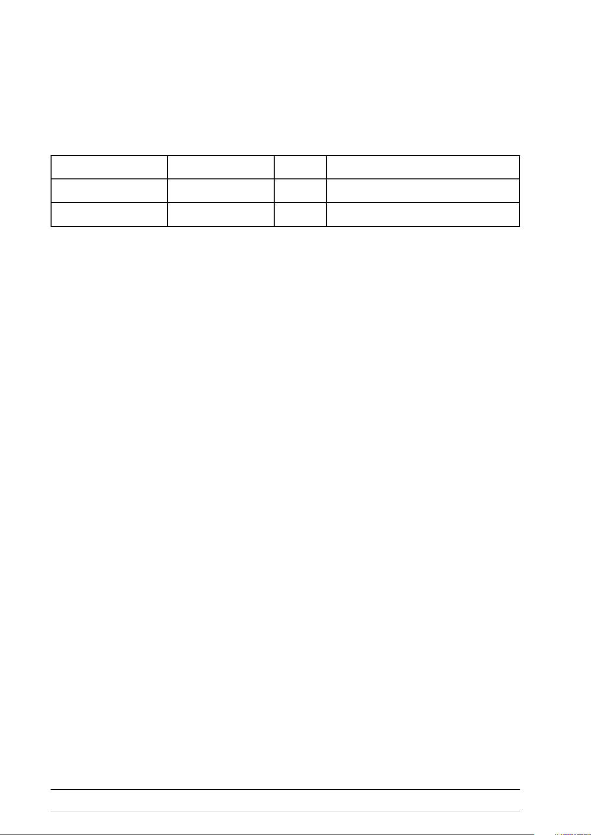
eleCtronIC CarrIer
desCrIptIon
All electronic boards are mounted on a special metal sheet
integrated in the bottom plate of the eBike III ergometers.
This metal sheet contains a grid of holes to mount all
possible combinations of electronic boards (e.g. LIU, SMU,
BPU).
metal Sheet carrier with mounting holeS (grid)
pcb direct connector SyStem
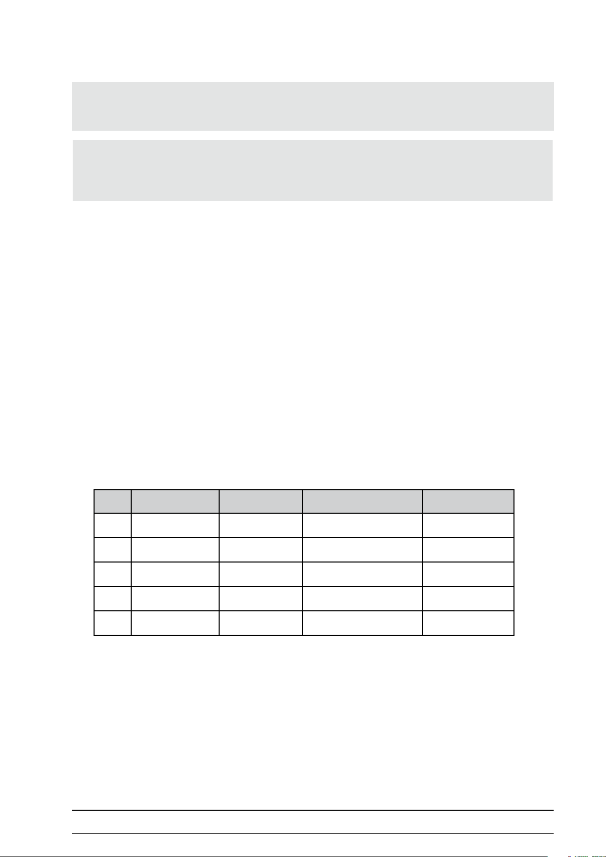
dIsMountIng of tHe eleCtronIC asseMBly group
1. Grab the eBike at handlebar and saddle and carefully
lay it sideways on one side.
2. Remove six screws (see picture) and ip the carrier
plate carefully aside.
3. Remove the connecting cables from the corresponding
boards.
4. The PCBs are mounted on spacers, screwed from
outside of the metal sheet carrier.
5. After removing these screws, the PCBs can be
removed.
metal Sheet carrier, aSSembled (bpu, Smu, liu)
6. After replacing a board, installation is performed by
following the steps in reverse order.
- 20 - eBike III basic / comfort 2018111-336 Rev. B
Page 21
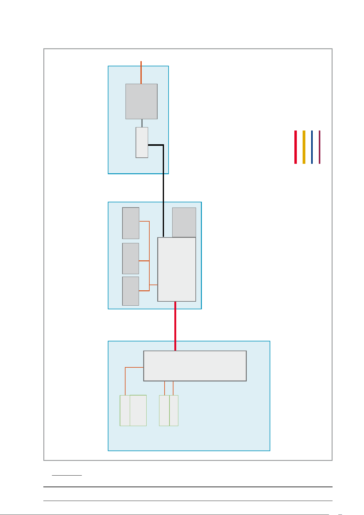
BloCk dIagraMs BIke ergoMeter eleCtronICs eBIke III
power cable
power
supply unit
Power supply
switch
24 V
RJ-45 Patchcable
PCB connector (direct)
Microfone cable
Connecting tube (cu)
rpm sensor
module
strain gauge
Brake unit + interface
brake
eddy current
Control unit
USB
RS-232
LIU
DTU
LCD
NIBP key
ebike iii baSic
keys for
saddlemotor,
service menu
patient rpm
2018111-336 Rev. B eBike III basic / comfort - 21 -
Page 22

cu connector
pressure
microphone
connector
patient rpm
service menu
NIBP key
LCD
saddlemotor,
keys for
Control unit
DTU
eddy current
brake
BPU
valves etc.
PCB connector (direct)
Microfone cable
Connecting tube (cu)
Bloodpressure module
pump
RJ-45 Patchcable
USB
LIU
RS-232
24 V
supply unit
module
switch
power
Brake unit + interface
strain gauge
rpm sensor
Power supply
power cable
ebike iii baSic with bloodpreSSure unit
- 22 - eBike III basic / comfort 2018111-336 Rev. B
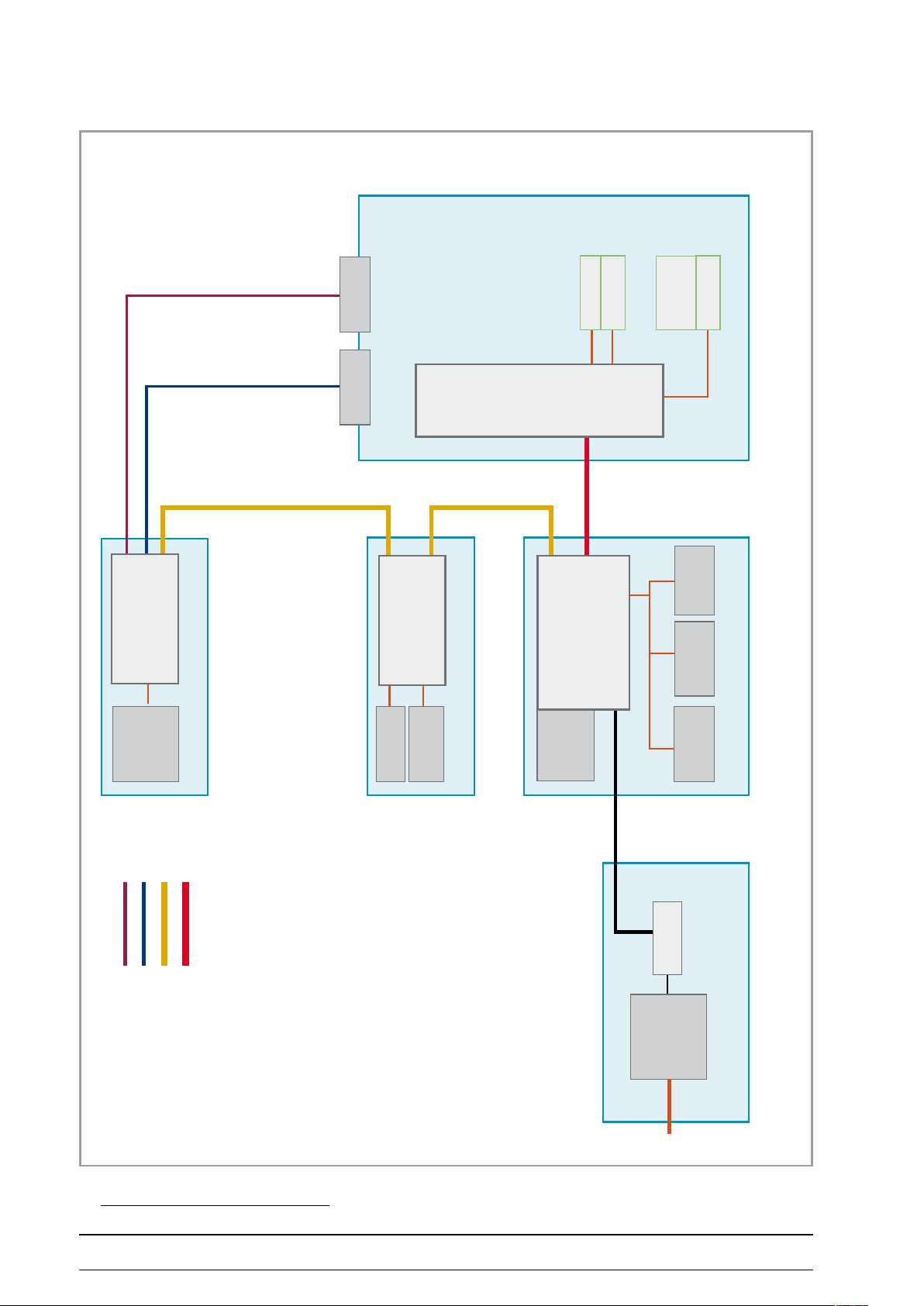
Page 23

Power supply
power cable
power
supply unit
switch
24 V
RJ-45 Patchcable
PCB connector (direct)
Microfone cable
Connecting tube (cu)
rpm sensor
module
strain gauge
Brake unit + interface
brake
eddy current
Control unit
USB
RS-232
LIU
motor
Motor saddle height
sensor
position
saddle height
SMU
DTU
LCD
NIBP key
ebike iii comfort
keys for
saddlemotor,
service menu
patient rpm
2018111-336 Rev. B eBike III basic / comfort - 23 -
Page 24
cu connector
pressure
microphone
connector
patient rpm
service menu
NIBP key
LCD
saddlemotor,
keys for
Control unit
DTU
eddy current
brake
BPU
valves etc.
Microfone cable
Connecting tube (cu)
Bloodpressure module
pump
RJ-45 Patchcable
PCB connector (direct)
position
sensor
SMU
saddle height
motor
Motor saddle height
USB
LIU
RS-232
24 V
supply unit
module
switch
power
Brake unit + interface
strain gauge
rpm sensor
Power supply
power cable
ebike iii comfort with bloodpreSSure unit
- 24 - eBike III basic / comfort 2018111-336 Rev. B
Page 25

wIrIng dIagraMs BIke ergoMeter eBIke III
Power supply
white
black
Main switch
white
brown
rpm module
X 2
RS 232
USB
Torque module
Eddy current brake
Brake unit
X 19 X 11X 14 X 13
red
blue
LIU PCB
Load regulation / interface
X 8
Patch cable
RJ-45
Control unit
ebike iii baSic
2018111-336 Rev. B eBike III basic / comfort - 25 -
Page 26

Microphone cable
Control unit
RJ-45
Patch cable
pump + valve
J4 to pump
J6 to valve
J 9
Bloodpressure module
X 8
Load regulation / interface
Brake unit
Eddy current brake
BPU PCB
LIU PCB
Direct PCB connector
blue
red
Torque module
X 19 X 11X 14 X 13
USB
RS 232
rpm module
X 2
white
brown
Main switch
white
black
Power supply
ebike iii baSic with bloodpreSSure unit
- 26 - eBike III basic / comfort 2018111-336 Rev. B
Page 27

Power supply
Main switch
rpm module
Torque module
white
white
black
brown
X 19 X 11X 14 X 13
X 2
RS 232
USB
Eddy current brake
Brake unit
Control unit
red
blue
RJ-45
LIU PCB
Load regulation / interface
X 8
Patch cable
Direct PCB connector
SMU PCB
Saddle motor
X 5 (2 pol) to motor
X10 (3 pol) to sensor
ebike iii comfort
2018111-336 Rev. B eBike III basic / comfort - 27 -
Page 28

Microphone cable
J 9
Control unit
pump + valve
J4 to pump
J6 to valve
X 5 (2 pol) to motor
X10 (3 pol) to sensor
Bloodpressure module
BPU PCB
Direct PCB connector
Saddle motor
SMU PCB
Direct PCB connector
Patch cable
Patch cable
X 8
RJ-45
Load regulation / interface
LIU PCB
blue
red
X 19 X 11X 14 X 13
Brake unit
Eddy current brake
Torque module
USB
RS 232
rpm module
X 2
white
brown
Main switch
white
black
Power supply
ebike iii comfort with bloodpreSSure unit
- 28 - eBike III basic / comfort 2018111-336 Rev. B
Page 29

Control unIts
dtu - Control unIt
The DTU board of the control unit is the “mainboard“ of
the eBike III electronics.
The DTU together with the LCD is mounted inside the
housing of the control unit.
Note
• The housing of the control unit CANNOT be opened!
• For repairs / upgrades the complete control unit has to be
replaced.
control unit
dtu board (top view) with patient rpm diSplay
dtu with lcd
2018111-336 Rev. B eBike III basic / comfort - 29 -
Page 30

dtu - patIent dIsplay
The patient display for rpm and the push buttons for
service menu control are internally connected by a at
cable and screwed into the housing.
dtu - ConneCtors
1 2 3
dtu patient diSplay / buttonS for Saddle height
1 LED for rpm zones
2 Display for rpm
3 Push buttons for saddle height (eBike III comfort) and
service menu control
1
dtu
1 RJ-45 connector (patch cable to LIU)
- 30 - eBike III basic / comfort 2018111-336 Rev. B
Page 31

load regulatIon and InterfaCe
lIu - load regulatIon and InterfaCe Board
The electronics of the LIU-PCB stabilizes the actual load of
the eddy current brake with given accuracy.
The signal of the rpm sensor (non-contact hall sensor)
and the feedback signal of the strain gauge module are
analyzed and the actual brake force adjusted.
In addition, the processor of the LIU board generates the
interface signals (RS-232 and USB) to external devices (e.g.
PC-ECG or ECG recorders).
Both signals (RS-232 and USB) are galvanically isolated
(opto couplers).
The LIU board is mounted directly on the electronic carrier
plate in the bottom of the ergometer.
The power supply (24 Volt) is connected to the LIU and fed
into the bus system.
The connection between DTU (control unit M) and LIU is
made by a patch cable (RJ-45 jacks); the other boards are
connected to the LIU by direct connectors.
2 3 4
1
liu board
1 direct connector for internal BUS system
2 connector to eddy current brake
3 RJ-45 connector for internal BUS system (DTU)
4 jumper for connecting the external COM module
5 RS-232 interface connector (galv. isolated)
6 USB interface connector (galv. isolated)
7 connector rpm sensor
8 connector DMS module (torque sensor)
9 connector power supply 24 V (from main switch)
5
6
789
2018111-336 Rev. B eBike III basic / comfort - 31 -
Page 32

nIBp Blood pressure unIt
asseMBly
The NIBP module consists of several components.
The complete measurement electronics, the deating valve
and the power drivers for the pump are placed on the
BPU board (see picture).
bpu meaSuring electronic board
1
The pump and the measuring valve are placed on a
separate sound and vibration absorbing foam carrier.
2
3
bpu meaSuring electronic board
1 microphone connector (J 9)
2 measuring valve connector (J 6)
3 pump connector (J 4)
1
2
3
foam carrier for meaSuring valve (1) and pump (2)
(with compenSating container 3)
When replacing the measuring valve, the silicon tube has
to be connected with the upper hose nipple of the valve
and the cable bended to a loop. The carefully slip the valve
back into the foam carrier.
replacing the valve
- 32 - eBike III basic / comfort 2018111-336 Rev. B
Page 33

plaCeMent of pressure tuBes (sCHeMatIC)
foam carrier
measuring valve
lter
BPU electronic board
pressure-
sensor 1
pressure-
sensor 2
deating
valve
check valve
pump
compensating container
sound
absorber
cu
connector
(in control unit)
BloCk dIagraM of CaBlIng of tHe Bloodpressure unIt
microphone
connector
(in control unit)
J 9
BPU electronic board
deating valve
J 6 J 4
2
measuring
valve
2
pump
2018111-336 Rev. B eBike III basic / comfort - 33 -
Page 34

Bpu - Blood pressure Board
The BPU electronics is responsible for analyzing the
microphone signals, controlling the valves and the pump.
The input of the microphone (1) is galvanically isolated, see
upper left in picture.
A redundant surveillance system (with two pressure
sensors (2) ) continously monitors the actual cu pressure
and the pump time.
The BPU board is connected to other PCBs by use of the
direct bus connector (3).
The measuring valve is connected to J6 (4) and the pump
to J4 (5).
1
4 5
2
2
bde- blood preSSure meaSuring board
3
pump
measuring valve
Note
• The BPU is ALWAYS the last module last module placed
in the “PCB chain“ on the electronic carrier.
• The SMU board is mounted between BPU and LIU.
ergometer blood preSSure unit, complete
- 34 - eBike III basic / comfort 2018111-336 Rev. B
Page 35

MIsCellaneous Modules
sMu - saddle HeIgHt Motor
The control of the saddle motor is performed by the SMU
board.
The SMU has one connector for the motor (1) and another
coded connector (2) for the position sensor (actual motor
position).
Motor and sensor are connected with special cables.
The SMU board is connected directly to the LIU (3) or BPU.
1 2
33
Smu board (top view)
2018111-336 Rev. B eBike III basic / comfort - 35 -
Page 36

MeCHanICal asseMBly
Controls and IndICators
1 Control unit
2 Speed readout for patient
2
1
3
3 Connectors (for blood pressure cu)
4 Adjustment of handlebar angle
5 Castors
6 Baseplate (small)
7 Leveling feet to adjust the ergometer to uneven oors
8 Sockets for power cord and connection cables
(underside of ergometer)
9 Power switch (toggle switch [I / 0]
10 Saddle adjustment with clamping lever
1 Control unit
2 Speed readout for patient
keys for saddle height motor adjustment
3 Connectors (for blood pressure cu)
4
10
9
8
7
6
5
ebike iii baSic
2
1
3
4
4 Adjustment of handlebar angle
5 Castors
9
6 Baseplate (large)
7 Leveling feet to adjust the ergometer to uneven oors
8
8 Sockets for power cord and connection cables
(underside of ergometer)
7
9 Power switch (toggle switch [I / 0] )
6
5
ebike iii comfort
- 36 - eBike III basic / comfort 2018111-336 Rev. B
Page 37

MountIng tHe HandleBar
HandleBar - adjust fIxture (InClInatIon)
1. Use an allen key to adjust the 2 screws.
2. Open the handlebar lever.
3. Start with a quarter turn clockwise for both screws.
4. Close the lever and check if the handlebar is secure.
5. The force of the lever can be adjusted by turning the
screw inside the lever.
6. Open the handlebar lever.
7. Turn the screw clockwise (a quarter turn) using a at
screwdriver.
8. Close the lever and check if the handlebar is secure.
HandleBar - dIsMountIng / MountIng
1. Open the handlebar lever and turn the handlebar
downwards.
2. Remove the allen screw from the lever.
2018111-336 Rev. B eBike III basic / comfort - 37 -
Page 38

3. Using a at screwdriver, loosen the screw
inside the handlebar lever by turning the screw
counterclockwise.
4. Unscrew the lever out of the terminal adapter by
turning the lever counterclockwise.
5. Remove the washer.
6. Remove the two allen screws and remove the rear part
of the terminal adapter.
7. The handlebar can be changed.
8. Follow the steps in reverse order to secure the
handlebar.
- 38 - eBike III basic / comfort 2018111-336 Rev. B
Page 39

reMove ergoMeter HousIng
plastIC sCrew seals (Caps)
The screws xing the plastic housing parts of the eBike
III basic and eBike III comfort are covered by small plastic
caps.
Due to the dierent screw sizes there are 5 dierent caps
used. The dierent caps are marked with small slots from
cap type 0 (no slot) up to cap type 4 (4 slots) - see picture.
plaStic cap with marking SlotS (type 4)
cap type 0
handlebar housing
The caps can only be removed by destroying them.
Before removing plastic parts of the housing, be sure to
have spare plastic caps available (PN 2018111-335).
cap type 1
eBike III basic
eBike III comfort
cap type 2
eBike III comfort
cap type 3
eBike III comfort
cap type 4
eBike III basic
2018111-336 Rev. B eBike III basic / comfort - 39 -
Page 40

dIsMountIng tHe HandleBar pole HousIng
1. Remove the two plastic caps (type 0) on both sides of
the handlebar pole housing
2. Using a small screwdriver, cut into the plastic caps
covering the screws and remove the caps
(the caps will later be replaced by spare ones;
P/N 2018111-335).
ebike iii
3. Remove the screws with an allen key tool.
4. The two parts of the handlebar pole housing can be
carefully removed.
5. Follow the steps in reverse order to reassemble the
handlebar pole housing.
- 40 - eBike III basic / comfort 2018111-336 Rev. B
Page 41

dIsMount pedal Cranks
1. Carefully lift the protective cover o the crank, using a
small at screw driver.
2. Plug the crank extractor onto the screw of the crank.
3. Loosen the screw with a wrench (17 mm).
4. Remove the screw and the lock washer.
(When mounting the cranks after repair use a torque
wrench to tighten the screw with a torque of
40 Nm.)
5. Turn the crank extractor and securely tighten the
screw completely (!!) into the winding of the crank
screw.
6. Use a wrench (17 mm) to remove the crank by
screwing the bolt onto the axis.
2018111-336 Rev. B eBike III basic / comfort - 41 -
Page 42

reMove HousIng of tHe eBIke III BasIC
reMove top Cover
1. Remove the saddle.
(When mounting the saddle after repair use a torque
wrench to tighten the screw with a torque of
25 Nm.)
2. Remove the lever for saddle height by turning it
counterclockwise.
3. Remove the two plastic caps (cap type 4) on both
sides.
4. Using a small screwdriver, cut into the plastic caps
covering the screws and remove the caps
(the caps will later be replaced by spare ones;
P/N 2018111-335).
5. Remove the two allen screws underneath the plastic
caps.
6. Remove the allen screw at the rear side of the top
cover.
- 42 - eBike III basic / comfort 2018111-336 Rev. B
Page 43

7. The top cover can be lifted and carefully removed.
reMove Inlays
1. Using a small at screwdriver, lift the inlay panel, and
carefully release the panel.
Note
• Avoid scratching the main plastic housing!
2. Continue to carefully loosen the remaining tabs until
the panel can be removed completely.
2018111-336 Rev. B eBike III basic / comfort - 43 -
Page 44

reMove sIdes of tHe HousIng
1. Using a small screwdriver, cut into the plastic caps
(cap type 1) covering the screws and remove the six
caps (3 on each side); the caps will later be replaced by
spare ones (P/N 2018111-335)
(see picture: items “A“).
2. Remove the three allen screws in the main side parts
(see picture: items “A“) and the two allen screws under
the removed inlays (picture: items “B“) on both sides.
A
B
B
AA
A
3. Unlock the metal bracket connecting both sides covers
of the housing by lifting it with a at screwdriver.
B
B
- 44 - eBike III basic / comfort 2018111-336 Rev. B
Page 45

4. The side covers of the housing can be removed by
lifting up the panels from the aluminum bottom plate
(see detail).
5. The drive unit, saddle mechanics, and power supply
are accessible.
6. Follow the steps in reverse order to assemble
the eBike III basic housing.
2018111-336 Rev. B eBike III basic / comfort - 45 -
Page 46

reMove HousIng of tHe eBIke III CoMfort
reMove top Cover
1. Remove the allen screw from the front part of the top
cover.
Using a small screwdriver, cut into the plastic cap
(cap type 3) covering the screw and remove the cap
on both sides; the caps will later be replaced by spare
ones (P/N 2018111-335).
2. Using two allen keys, remove the long screw securing
the top cover to the housing brackets.
- 46 - eBike III basic / comfort 2018111-336 Rev. B
Page 47

3. The top cover can be easily removed.
reMove HousIng BraCkets
1. Using a small screwdriver, cut into the two plastic
caps (top: cap type 2, bottom: cap type 1) covering the
screws and remove the caps on both sides.
The caps will later be replaced by spare ones
(P/N 2018111-335).
Note
• The top plastic cap (cap type 2) is not symmetric - when
reassembling the bracket housing, the indication mark of
this cap (two notches) has to be positioned at the top!
2018111-336 Rev. B eBike III basic / comfort - 47 -
Page 48

2. Insert a small screwdriver or a round 3 mm pin into
the small holes (front and rear of bracket top) to
unlock the housing.
3. Remove the two metal brackets connecting the two
sides of the housing brackets.
4. Starting at the bottom, release the housing panels
from the brackets in the side housing covers and
remove.
- 48 - eBike III basic / comfort 2018111-336 Rev. B
Page 49

reMove HousIng sIde panels
1. Remove the four screws securing the housing panels
to the metal chassis.
2. Lift the housing covers to release the covers from the
brackets in the aluminium base and remove.
3. The drive unit, saddle mechanics, and power supply
are accessible.
4. Follow the steps in reverse order to assemble the
eBike III comfort housing side panels.
2018111-336 Rev. B eBike III basic / comfort - 49 -
Page 50

saddle pIllar exCHange (eBIke III BasIC)
1. Follow the steps in “Remove housing of the eBike III
basic“ on page 42
2. Loosen the limiting screw for the saddle pillar with an
Allen key.
3. Remove the lever.
4. Loosen the Philips screw.
5. Remove the clamping plate and the threaded plate.
6. The saddle pillar can be pulled out.
7. Follow the steps in reverse order to assemble the
saddle pillar.
- 50 - eBike III basic / comfort 2018111-336 Rev. B
Page 51

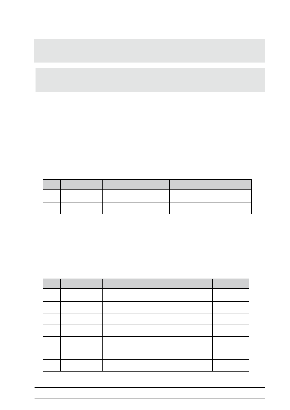
saddle Motor (eBIke III CoMfort)
1. Follow the steps in “Remove housing of the eBike III
comfort“ on page 46.
2. Disconnect the two connection cables of the saddle
motor from PCB Interface SMU.
3. Remove the saddle.
4. Loosen and remove the bottom xation of the saddle
motor; screw and nut are accessible via a hole at the
bottom.. Use a socket wrench and an Allen key from
the counter side to dismount the screw.
Note
Try to position the saddle at mid-level setting before removing
the saddle motor.
5. Unscrew the four screws of the saddle guide tube with
a fork wrench (13mm):
Start by removing screws (1) to (3) (see picture).
Loosen screw (4) and move the guide backwards until
the screw releases and can be removed.
1
3
2
4
2018111-336 Rev. B eBike III basic / comfort - 51 -
Page 52

6. Remove the complete saddle motor unit from the
ergometer.
7. Loose both TORX screws at the top
8. Push the saddle motor inside the saddle tube to allow
the cylindrical pin to be removed from the saddle
shaft.
9. Pull the saddle motor out of the saddle guide tube.
10. Follow the steps in reverse order to install the new
motor.
- 52 - eBike III basic / comfort 2018111-336 Rev. B
Page 53

straIn gauge Module exCHange
1. Follow the steps in
“Remove housing of the eBike III basic“ on page 42
or
“Remove housing of the eBike III comfort“ on page
46.
2. Disconnect the cable of the strain gauge module from
the LIU electronics (the electronic housing is located
underneath the bottom plate).
Remove the toroid ferrite o the cable.
3. Remove the two allen screws securing the strain
gauge module.
4. Remove the strain gauge module (1) and the heat sink
(2) and carefully pull the cable through the hole in the
bottom plate.
5. When installing the new module carefully allign the
module and the heat sink in parallel to the eddy
current brake.
6. When securing the module in place, carefully tighten
the two screws; excessive force may damage the
module.
2
1
7. Lead the connecting cable through the hole in the
bottom plate.
Lead the cable through the toroid ferrite and
reconnect it to the LIU electronic board.
2018111-336 Rev. B eBike III basic / comfort - 53 -
Page 54

rpM Module exCHange
1. Follow the steps in
“Remove housing of the eBike III basic“ on page 42
or
“Remove housing of the eBike III comfort“ on page
46.
2. Disconnect the cable of the RPM module from the
LIU electronics (the electronic housing is located
underneath the bottom plate).
3. Use a long, exible, magnetic Allen key to remove the
two Allen screws securing the RPM module from the
bottom plate.
4. Carefully remove the RPM module through the hole in
the bottom plate.
5. Insert the new RPM module carefully through the hole
in the bottom plate into the load unit.
6. From the top of the load unit carefully tighten the two
Allen screws..
7. Connect the cable to the appropriate connector on the
LIU board (marked as “RPM brake“).
- 54 - eBike III basic / comfort 2018111-336 Rev. B
Page 55

load unIt
asseMBly
The eBike III ergometers are equipped with an identical
load unit (brake unit) with an eddy current brake of
1000 Watt.
load unIt replaCeMent
aSSembly of the load unit
1 Galvanized steel housing
2 Precision bearings
3 Calibrated strain gauge module
4 Eddy current brake (1000 W)
5 Special drive belt
1. Grab the eBike at handlebar and saddle and carefully
lay it sideways on one side.
2. Disconnect all cables from the electronic boards.
3. The load unit is secured with six Allen key screws on
the ergometer chassis.
Brace the load unit from falling over and then using a
socket wrench, loosen the screws.
Use a torque wrench to tighten the screws of the new load
unit with a torque of 25 Nm.
2018111-336 Rev. B eBike III basic / comfort - 55 -
Page 56

power swItCH replaCeMent
1. The power switch is mounted between the two rear
parts of the ergometer housing.
2. Follow the steps in
“Remove housing of the eBike III basic“ on page 42
or
“Remove housing of the eBike III comfort“ on page
46.
3. Remove the cables from the defect power switch and
place them on the appropriate contacts of the new
switch.
If the cable between switch and LIU board has to be
replaced, open the electronic carrier (underneath the
eBike), disconnect the power cable from the LIU board
and replace it with the spare cable included in the
package..
4. Secure the cables with a cable strap
power connector (from main Switch) on liu board
When reassembling the housing:
5. Slide the plastic cover of the power switch in the
appropriate slot in one side part of the housing.
6. During assembly of the side parts take care, that
the plastic cover of the main switch ts into the
corresponding slot of the other side part.
- 56 - eBike III basic / comfort 2018111-336 Rev. B
Page 57

power supply unIt replaCeMent
1. The power supply is mounted in the rear of the
ergometer.
2. Remove the mounting bracket (2 screws).
3. Replace the power supply unit and secure the
mounting bracket again.
4. Remove the power supply cable from the main switch
and connect the cable of the new power supply
accordingly
5. Secure the cables with a cable strap
When reassembling the housing:
6. Slide the plastic cover of the power switch in the
appropriate slot in one side part of the housing.
7. During assembly of the side parts take care, that
the plastic cover of the main switch ts into the
corresponding slot of the other side part.
2018111-336 Rev. B eBike III basic / comfort - 57 -
Page 58

reMove Control unIt
1. To remove the control unit, loosen both Phillips-head
screws on the side of the control terminal.
2. Remove the control terminal from the support.
3. Disconnect the patch cable (1) from the DTU board.
1
eBike III with blood pressure measurement
• Disconnect microphone cable (2) and cu hose (3)
(see following instructions and pictures)
Note
• The housing of the control unit CANNOT be opened!
• For repairs / upgrades the complete control unit has to be
replaced.
2
3
- 58 - eBike III basic / comfort 2018111-336 Rev. B
Page 59

4. Disconnect the microphone cable at the 3 pole
connector (see picture):
Press the small clip downwards (1),
and pull out the connector carefully (2) with clip
pressed downwards.
1
2
5. Disconnect the blue hose at the hose connector
(see picture).
Warning
Do not pull at the microphone cable to disconnect the
microphone connector - the cable will be damaged..
2018111-336 Rev. B eBike III basic / comfort - 59 -
Page 60

software Control terMInal
turnIng tHe systeM on
The ergometer is powered on by pressing the power switch
to the ON position.
The ergometer runs a self-test. The Self-Test screen is
displayed.
eBike III
settIngs Control terMInal
The control unit is controlled remotely by a host device (for
example, CASE, CardioSoft).
No setup is required by the user.
Selftest running
Self-teSt Screen
Note
• Instruct the patient not to pedal while the ergometer is
powering and during the self-test.
• Apply the blood pressure cu to the patient AFTER the
ergometer has been powered on and the self-test completed.
• If an error message appears displays after the self-test,
please refer to the Addendum / Error Messages section
for instruction.
All conguring is done through the service menu only.
- 60 - eBike III basic / comfort 2018111-336 Rev. B
Page 61

servICe Menu
To activate the service menu, the ergometer has to be
powered o and on again.
As soon as the self test displays on the ergometer LCD,
press the two arrow keys simultaneously:
To prevent settings from being changed in error, the
service menu is “protected“ with a password.
Select “999“ with the arrow keys and conrm by pressing
NIBP.
The service menu with the following parameters displays:
• Contrast
• ECG type
• NIBP mmHg / kPa
• NIBP Beep
• Baudrate 8N2
• Analog Calibration
• Software Update
• Dynamic Load Calibration
• Saddle Calibration
• NIBP Calibration
• NIBP Test
• System Cong.
• Error log
• Manual load
• Reset DMS values
Service Code
paSSword for Service menu
999
Note
• The service menu in the ergometers is available in
english only.
• Depending on the actual ergometer conguration,
not all settings are enabled.
• Leaving the service menu is only possible by powering the
device o.
• The following descriptions are not in the same order as in
the service menu.
Navigate through the menus by using the arrow keys
(saddle height) to position the cursor bar.
Conrm the selection by pressing NIBP (to the right
of the LCD).
Service Menu
Contrast
ECG type
NIBP mmHg / kPa
NIBP Beep
Baudrate 8N2
Analog Calibration
Software update
Select the desired parameter using the arrow keys and
conrm by pressing NIBP.
2018111-336 Rev. B eBike III basic / comfort - 61 -
Selection of parameterS in Service menu
Page 62

Contrast
The contrast of the LCD can be adjusted between
0 to 100 %.
eCg type
The selected ECG Type determines the communication
method with the ECG recorder, PC-based ECG system, etc.
To prevent settings from being changed in error, the menu
is protected with a password.
Using the arrow keys, enter ”003” and conrm the entry by
pressing NIBP.
Contrast
adjuSting the diSplay contraSt
50 %
ECG Type
003
All eBike III ergometers support the following
communication modes:
• Digital (default)
The communication with the ergo meter is entirely
controlled with digital commands.
• Analog / Digital (optional)
An analog voltage controls the load - blood pressure
measurements can be initiated with digital commands.
To use the ”Analog/Digital” communication mode,
the eBike III ergometers have to be equipped with the
optional „COM-Modul (PN 201118-340)“.
Select the communication mode and conrm by pressing
NIBP.
entering the ekg type paSSword
ECG-Type
Digital
Analog / Digital
Selecting the ergometer communication mode
Note
• The ECG Type needs to be selected only when the ergometer is connected to an ECG unit. The selection is part of
the installation procedure.
- 62 - eBike III basic / comfort 2018111-336 Rev. B
Page 63

nIBp Beep
The tone signal for the systolic pulse (during NIBP
measurement) can be set to on or o.
Select the desired setting and conrm by pressing NIBP.
nIBp MMHg / kpa
The units for the NIBP values displayed can be changed.
Select the desired units and conrm by pressing NIBP.
NIBP Beep
On
Off
beep during bp meaSurementS
NIBP mmHg / kPa
mmHg kPa
unit Selection for nibp valueS
2018111-336 Rev. B eBike III basic / comfort - 63 -
Page 64

dynaMIC load Cal.
To perform a dynamic load calibration, a calibrated
dynamic test bench is needed.
The dynamic calibration of the load unit is described in the
session “„Dynamic Load Calibration“ on page 72.
software update
For a description of a software update of the ergometer
(rmware) see the session „Software update“ on page
78.
Baudrate 8n2
The baudrate can be selected between 1200 Baud and
115000 Baud.
Default value for standard ergometers is 4800 Baud.
Select the desired parameter using the arrow keys and
conrm by pressing NIBP.
saddle CalIBratIon
(eBike III comfort only)
This parameter is used to adjust the electrical saddle motor
(display scale 1-40).
Select “SET TOP Position“ and conrm by pressing NIBP.
Baudrate 8N2
1.200
2.400
4.800
9.600
19.200
38.400
76.800
Selection of Serial baudrate
Saddle Calibration
SET TOP Position
SET BOTTOM Position
EXIT
Use the arrow keys to move the saddle to the desired top
position (99 cm ± 0,5 cm above bottom plate; see picture)
and conrm “SET“ by pessing NIBP.
Saddle Calibration
TOP Position
Adjust with
SET Height: 22
calibration of Saddle height top poSition
- 64 - eBike III basic / comfort 2018111-336 Rev. B
Page 65

Select „SET BOTTOM Position“ and conrm by pressing
NIBP.
Saddle Calibration
SET TOP Position
SET BOTTOM Position
EXIT
Use the arrow keys to move the saddle to the desired
bottom position (69 cm ± 0,5 cm above bottom plate; see
picture) and conrm “SET“ by pessing NIBP.
Select “EXIT“ and conrm by pressing NIBP to return to the
service menu
Saddle Calibration
Bottom Position
Adjust with
SET Height: 5
calibration of Saddle height botom poSition
Saddle Calibration
SET TOP Position
SET BOTTOM Position
EXIT
top: 99 CM
BottoM: 69 CM
2018111-336 Rev. B eBike III basic / comfort - 65 -
Page 66

Manual load
A manual load can be set between 1 - 999 Watt.
Use the arrow keys and set the desired value by pressing
NIBP.
Pressing NIBP at 0 Watt (EXIT) returns to the service menu.
systeM ConfIg.
Manual load
75 Watt
Manual load
0 Watt
EXIT
The hardware conguration of the ergometer is dened in
this setup.
Select the module / option and change the setting to I
if the module is integrated in the actual ergometer.
The last selection “EXIT“ returns to the service menu.
System Cong.
Saddle engine 0 I
NIBP-Modul 0 I
Analog Interface 0 I
EXIT
Settting of ergometer configuration
Note
• ”Analog Interface” is set to “I” only if a MAC5500 is
connected to the eBike III.
In conjunction with this setting, a special adapter
(COM module PN 2018111-340) has to be installed to add
an analog interface to the eBike III.
- 66 - eBike III basic / comfort 2018111-336 Rev. B
Page 67

error log
The software of the eBike III ergometers stores internal
error messages in a special memory area (Error Logs) and
also stores statistics for the quality of the blood pressure
measurements (NIBP Logs).
These error messages can be checked and cleared in this
menu.
To display the stored error messages select „Show Error
Logs“ and conrm with by pressing NIBP.
The rst error message is displayed:
Source: The unit generating the error
Err.Code: Corresponding error code of the software
Quantity: Number of occurences of this error
Error log
Err. Log Quantity: 2
Show Error Logs
Show NIBP Logs
Clear Error Logs
Clear NIBP Logs
EXIT
error log memory
Error No.: 1 / 3
Source: SMU
Err.Code: 0100
Quantity: 1
Using the arrow keys, the following error messages can be
displayed.
Press the NIBP (Exit) to close the error log displayed.
To display the bloodpressure statistics, select „Show NIBP
Logs“ and conrm by pressing NIBP.
The statistics are displayed:
NIBP failed: Number of failed measurements
Mic.Level 1...5: Number of measurements with the
shown microphone signal strength
(5 = best signal)
EXIT
diSplaying a Single error
NIBP failed: 2
Mic. level 1: 2
Mic. level 2: 5
Mic. level 3: 3
Mic. level 4: 9
Mic. level 5: 7
EXIT
error log memory nibp
2018111-336 Rev. B eBike III basic / comfort - 67 -
Page 68

nIBp test / nIBp CalIBratIon
This menu is enabled, if the ergometer is equipped with an
automatic NIBP module and this module is activated.
Test and calibration of the NIBP module is described in
session „Calibration of Blood pressure unit“ on page 75..
analog CalIBratIon
This function is used to allign the analog remote signals
(input and output) to the corresponding ECG devices.
The eBike III ergometers have to be equipped with the
optional „COM Module (PN 201118-340)“. This module is
connected with a small cable to the 9-pin DSUB connector
and xed to the chassis with a plastic velcro tape.
In addition, a jummper connector has to be installed on
the LIU board.
The COM module handles one analog input and ve analog
output signals from/to external devices.
Note
• To align the analog load signals, the corresponding ECG
recorder should be connected as a reference voltage
source.
• Disconnect the RS232 or USB cable, if connected.
• The alignment of the analog signals can be controlled
after exiting the service menu (e.g. by starting a remote
controlled stress test).
Signal aSSignment of analog connector (com module)
Pin 1 : INPUT Load
Pin 2:
Pin 3: reserved - do not connect
Pin 4: OUTPUT BP heartrate
Pin 5: OUTPUT Load
Pin 6: OUTPUT Diastole
Pin 7: OUTPUT rpm
Pin 8: OUTPUT Systole
Housing: Signal GND
reserved - do not connect
Select the analog signal to be aligned and conrm
by pressing the NIBP key.
Analog Calibration
Input 1 Load
Output 1 Load
Output 2 Heart.
Output 3 Syst.
Output 4 Diast.
EXIT
alignment of analog input / output SignalS
- 68 - eBike III basic / comfort 2018111-336 Rev. B
Page 69

alIgnMent “Input: analog load Control“
IN-Volt: displays the voltage at the analog input
Set the ECG recorder output to a low load value
(for example 20 Watt).
The corresponding voltage is displayed (IN-Volt).
Wait until the voltage has settled.
Select “OFFSET“ and conrm by pressing NIBP.
Use the arrow keys to set the load value to the ECG
recorder vaue (for example 20 Watt) and conrm by
pressing NIBP.
The setting is stored in the ergometer.
INPUT 1 Load
IN-Volt: 0.10 V
OFFSET 20 Watt
GAIN 300 Watt
EXIT
alignment of analog input „load“
INPUT 1 Load
IN-Volt: 0.10 V
OFFSET 20 Watt
GAIN 300 Watt
EXIT
Set the ECG recorder output to a high load value
(for example300 Watt).
The corresponding voltage is displayed (IN-Volt).
Wait until the voltage has settled.
Select “GAIN“ and conrm by pressing NIBP.
Use the arrow keys set the load value to the ECG recorder
vaue (for example 300 Watt) and conrm by pressing NIBP.
The setting is stored in the ergometer.
offSet alignment of analog input „load“
INPUT 1 Load
IN-Volt: 3.05 V
OFFSET 20 Watt
GAIN 300 Watt
EXIT
alignment of analog input „load“
INPUT 1 Load
IN-Volt: 3.05 V
OFFSET 20 Watt
GAIN 300 Watt
EXIT
Setting range:
OFFSET: range from 20 to 1000 Watt in 10 Watt steps
GAIN: range from 20 to 1000 Watt in 10 Watt steps
2018111-336 Rev. B eBike III basic / comfort - 69 -
gain alignment of analog input „load“
Page 70

alIgnMent “ouput: analog load value“
Note
• Analog outputs are not used with standard connection to
CardioSoft / Case / MAC/ 2000 / MAC 5500
The output voltage representing a special load value of the
ergometer is dened with this setting.
It is possible to adjust the voltage and / or the load value.
Select the parameter using the arrow keys and conrm by
pressing NIBP
Use the arrow keys to set the load value and conrm by
pressing NIBP.
Setting range:
GAIN:(voltage) 20 mV to 10000 mV in steps of 2 mV
GAIN (load) 20 to 999 Watt in steps of 10 Watt
OUTPUT 1 Load
GAIN 3000 mV
GAIN 300 Watt
EXIT
OUTPUT 1 Load
GAIN 3000 mV
GAIN 300 Watt
EXIT
alignment of analog output „load“
alIgnMent “output: analog Heartrate“
The output voltage representing a special heart rate is
dened with this setting.
It is possible to adjust the voltage and / or the heartrate
value.
The setting is performed as described previously under
Alignment “Ouput: Analog Load value“
Setting range:
GAIN (voltage): 500 to 2000 mV in
2 mV steps
GAIN (heartrate): 50 to 250 bpm in
10 bpm steps
OUTPUT 2 Heart
GAIN 1000 mV
GAIN 100
♥
EXIT
- 70 - eBike III basic / comfort 2018111-336 Rev. B
Page 71

alIgnMent “output: analog systole“
The output voltage representing the systolic value is
dened with this setting.
It is possible to adjust the voltage and / or the systolic
value.
The setting is performed as described previously under
Alignment “Ouput: Analog Load value“
Setting range:
GAIN (voltage): 500 to 2000 mV in
2 mV steps
GAIN (systole): 50 to 250 mmHg in
5 mmHg steps
alIgnMent “output: analog dIastole“
The output voltage representing the diastolic value is
dened with this setting.
It is possible to adjust the voltage and / or the diastolic
value.
The setting is performed as described previously under
Alignment “Ouput: Analog Load value“
Setting range:
GAIN (voltage): 500 to 2000 mV in
2 mV steps
GAIN (diastole): 50 to 250 mmHg in
5 mmHg steps
OUTPUT 3 Systole
GAIN 1000 mV
GAIN 100 mmHg
EXIT
OUTPUT 4 Diastole
GAIN 1000 mV
GAIN 100 mmHg
EXIT
alIgnMent „output: rpM“
The output voltage representing the actual rpm value is
dened with this setting.
It is possible to adjust the voltage and / or the rpm value.
The setting is performed as described previously under
Alignment “Ouput: Analog Load value“
Setting range:
GAIN (voltage): 200 to 1000 mV in
2 mV steps
GAIN (rpm): 30 to 130 rpm in
5 rpm steps
OUTPUT 5 rpm
GAIN 1000 mV
GAIN 50 rpm
EXIT
2018111-336 Rev. B eBike III basic / comfort - 71 -
Page 72

alIgnMent / CalIBratIon
dynaMIC load CalIBratIon
• Dismount BOTH (!) pedal cranks of the eBike III - see
“Dismount pedal cranks“ under section „Dismount
pedal cranks“ on page 41.
• Follow the operator manual from the manufacture
of calibration device being used to connect the
calibration device with the axis of the eBike III.
When a dynamic calibration is performed, the measured
actual load values are entered into the ergometer software.
The ergometer calculates the exact characteristic load
curve for regulating the eddy current brake.
The following load / rpm combinations have to be
measured during the calibration process:
• oset at no load / no rotations
• 50 Watt at 50 rotations / min
• 50 Watt at 110 rotations / min
Note
• This session describes the dynamic load calibration of the
eBike III as a manual „step-by-step“ procedure.
• When using the ergoline calibration bench (“ergoline
ergotest 550“ - order direct from Ergoline P/N 705890), an
automatic dynamic load calibration is possible -
please refer to the operator manual of the ergotest 550
device
• 400 Watt at 110 rotations / min
To activate the service menu the ergometer has to be
switched o and on again.
As soon as the self test appears on the ergometer display,
press the two softkeys synchronously:
To prevent settings from being changed by chance, the
service menu is „protected“ by a password.
Select „999“ with the arrow keys and conrm with NIBP.
Service Code
999
Navigate through the menus by using the arrow keys
(saddle height) to position the cursor bar.
Conrm the selection by pressing NIBP (to the right
of the LCD).
- 72 - eBike III basic / comfort 2018111-336 Rev. B
paSSword for Service menu
Page 73

Select „Dynamic load calibration“ and conrm with NIBP
Service Menu
Contrast
ECG Type
Baudrate 8N2
Analog Calibration
Software update
Dynamic Load Calibr.
Saddle Calibration
Selection of parameterS in Service menu
• Start the oset calibration process with NIBP
• The line „DMS“ shows:
stored DMS value / actual DMS value
• By pressing NIBP (START) the actual value is averaged
for 5 sec and stored
Dynamic Load Cal.
Calibration offset
Gain: 1,00
DMS: 3277 / 3219
RPM: 0 B 0 P
Load: 0 SW 0 AW
START
dynamic load offSet calibration - waiting for Start
Dynamic Load Cal.
Calibration offset
Gain: 1,00
DMS: 3277 / 3222
RPM: 0 B 0 P
Load: 0 SW 0 AW
WAITING...
dynamic load offSet calibration - averaging
• Press NIBP (START) to start calibration step #1
• The eBike III automatically sets the load to 50 Watt
• Set the calibrator unit to 50 rpm
• The line „RPM“ shows the measured rotations/min
(issued by the calibrator unit)
[the value „P“ is not used in the eBike III)
• The line „Load“ shows the target load in Wattautomatically set by the eBike III (e.g. 50 Watt)
[the value „AW“ is not used in the eBike III)
• Wait approx. 20 seconds, until the load display is
stable
• By using the arrow keys, input the actual measured
load value of the calibrator (e.g. 51,3 Watt)
• Store the value with SET.
Dynamic Load Cal.
Dyn. Calibration
Gain: 1,00
DMS: 3219 / 3219
RPM: 0 B 0 P
Load: 0 SW AW
START
dynamic load calibration Step 1 - waiting for Start
Dynamic Load Cal.
At 50 /50 W 51,3 W
Gain: 1,00
DMS: 3219 / 3219
RPM: 50 B 0 P
Load: 50 SW AW
SET
dynamic load calibration Step 1 - input load value
2018111-336 Rev. B eBike III basic / comfort - 73 -
Page 74

• Set the calibrator unit to 110 rpm.
• Press NIBP (START) to start calibration step #2
• Wait approx. 20 seconds, until the load display is
stable
Dynamic Load Cal.
Dyn. Calibration
Gain: 1,00
DMS: 3219 / 3219
RPM: 110 B 0 P
Load: 50 SW AW
START
dynamic load calibration Step 2 - waiting for Start
• By using the arrow keys, input the actual value of the
calibrator (e.g. 50,8 Watt) at the ergometer.
• Store the value with SET.
• The eBike III automatically sets the load to 400 Watt
• Wait approx. 20 seconds, until the load display is
stable
Dynamic Load Cal.
At 110 /50 W 50,8 W
Gain: 1,00
DMS: 3219 / 3219
RPM: 110 B 0 P
Load: 50 SW AW
SET
dynamic load calibration Step 2 - input load value
Dynamic Load Cal.
Dyn. Calibration
Gain: 1,00
DMS: 3219 / 3219
RPM: 110 B 0 P
Load: 400 SW AW
START
dynamic load calibration Step 3 - waiting for Start
• By using the arrow keys, input the actual value of the
calibrator (e.g. 403,2 Watt) at the ergometer.
• Store the value with SET.
The successfull completion of the dynamic load calibration
is conrmed.
• Stop the calibration unit.
• Press NIBP to exit the Calibration programm
Dismount the calibration unit and reassemble the cranks /
pedals to the eBike.
Dynamic Load Cal.
At 110 /400 W 403,2 W
Gain: 1,00
DMS: 3219 / 3219
RPM: 110 B 0 P
Load: 400 SW AW
SET
dynamic load calibration Step 3 - input load value
Dynamic Load Cal.
Calibration successfull
EXIT
dynamic load calibration SucceSSfull
- 74 - eBike III basic / comfort 2018111-336 Rev. B
Page 75

CalIBratIon of Blood pressure unIt
Recommended components:
• Calibrated pressure measuring device (mmHg)
(manometer)
• Compensating container with 500 ml volume (min.)
• Hand pump
• Adapter for eBike cu connector
• Connecting tubes with t-adaptors
calibrated preSSure meaSuring device (mmhg)
compenSating container (example)
hand pump
adapter for ebike cuff connector
2018111-336 Rev. B eBike III basic / comfort - 75 -
Page 76

All the components are connected by tubes (one pressure
M
compensating container
500 ml
manometer
hand pump
Connecting tubes
Control unit
system) and connected to the cu connector of the
ergometer control terminal (use cu adaptor).
calibration Setup nibp
nIBp test
This function is used to check the internal pressure system
(pressure sensor, closeness, leakage etc.).
Select “NIBP Test“ in the service menu and conrm by
pressing NIBP.
Use the hand pump to apply a xed pressure to the
system.
The actual pressure value is displayed.
Compare the displayed ergometer value with the value of
the manometer.
The maximum allowed deviation is +/- 3mmHg.
Select EXIT (and conrm by pressing NIBP) to return to the
service menu.
NIBP Test
NIBP pressure
123 mmHg
CLOSE VALVE
EXIT
teSt of the internal nibp preSSure SyStem
Note
• If the applied pressure reaches 320 mmHg, the internal
safety valve is opened.
Select „Close valve“ (and conrm by pressing NIBP) to
continue with the NIBP-Test.
- 76 - eBike III basic / comfort 2018111-336 Rev. B
Page 77

nIBp CalIBratIon
This function allows the calibration of the internal pressure
measurement system.
Select „NIBP Calibration“ in the service menu and conrm
by pressing NIBP.
Oset calibration
During this calibration NO pressure should be present in
the system.
The cu connector (self closing) has to be opened (use cu
connector).
1. Remove cu.
2. Connect the cu connector with a short tube.
3. The actual pressure value is displayed.
4. Select SET and conrm by pressing NIBP.
5. The zero value is averaged and stored
Calibration with 200 mmHg
Connect the complete measurement system (hand pump,
manometer and compensating container) as described in
„NIBP test“.
NIBP Calibration
Offset: 0 mmHg
SET
EXIT
preSSure calibration - offSet
NIBP Calibration
Apply 200 mmHg
6. Using the hand pump, apply a xed pressure of
200 mmHg to the system
(control by the external manometer).
7. Wait several seconds until the pressure is stable;
correct the pressure if necessary.
8. Select SET and conrm by pressing NIBP.
9. The NIBP calibration is nished
Select EXIT (and conrm by pressing NIBP) to return to the
service menu.
2018111-336 Rev. B eBike III basic / comfort - 77 -
SET
EXIT
preSSure calibration - gain
Page 78

software update
To load a new version of the internal software into the
eBike III ergometers; a PC or Laptop with USB or a serial
port (RS-232) is needed.
To use the ergometer USB port, a special driver has to be
installed on the PC (virtual COM driver).
Copy the complete software package onto the PC and
uncompress it.
Connect the PC or Laptop with a serial cable or USB cable
to the egometer (Port 1 oder USB).
The software update is initiated in the service menu.
To activate the service menu, the ergometer has to be
powered o and on again.
Note
• Always use the latest software version for the appropriate
ergometer.
• Use only the PC update program included in the software
package.
As soon as the self test displays on the ergometer LCD,
press the two arrow keys simultaneously:
To prevent settings from being changed in error, the
service menu is “protected“ with a password.
Select “999“ with the arrow keys and conrm by pressing
NIBP.
eBike III
Selftest running
Self-teSt Screen
Service Code
999
paSSword for Service menu
The complete handling of the menues is done using the
arrow keys (saddle height) to position the bar cursor and
the NIBP key (near the display) to conrm the selection.
- 78 - eBike III basic / comfort 2018111-336 Rev. B
Page 79

The service menu displays.
Select “Software update“ with the arrow keys and conrm
by pressing NIBP.
Service Menu
Contrast
ECG type
NIBP mmHg / kPa
NIBP Beep
Baudrate 8N2
Analog Calibration
Software update
Selection of parameterS in Service menu
The current version of software installed is displayed.
Select “Show Software Rev.“ and conrm by pressing NIBP
to display the installed software versions of the dierent
electronic modules.
Grp: name of the module
Ap-SW: current installed version
(if =0 no connection to module)
X: XCUT of software-version (always 0)
S-No.: serial number of PCB, if electronically available)
Press the NIBP key again to display the installed bootloader
versions of the dierent electronic modules.
Grp: name of the module
Op-SW: required software version
(has to be equal to the Ap-SW in previous display)
BootLo: actual bootloader version of PCB
Software Update
GF 1.0
UPDATE
Show Software Rev.
EXIT
Grp Ap-SW X S-No.
DTU 1.0 0 910
LIU 1.0 0 117
SMU 1.0 0 17
Grp: Op-SW: BootLo:
DTU 1.0 0.1
LIU 1.0 0.1
SMU 1.0 0.1
Press NIBP to exit the version display.
1. Start the software update by selecting „Update“ and
conrm by pressing NIBP.
EXIT
Software Update
GF 1.0
UPDATE
Show Software Rev.
EXIT
2018111-336 Rev. B eBike III basic / comfort - 79 -
Page 80

2. Start the PC- update program by double-clicking
ergoselect.exe .
3. Adjust the serial (or virtual) COM-Port used for the
connection with the ergometer.
4. Click CONNECT to establish the software connection.
As soon as the connection is established, the START button
becomes active (or an error message displays).
Initiate the update by pressing „START“.
The update progress is displayed on the ergometer LCD
and on the PC.
After the update is performed, the ergometer has to be
powered o and on again.
Software Update
is running
DTU FLASH writing 12 %
Software update in progreSS
Software Update
Update nished
Switch off power
Software update finiShed
- 80 - eBike III basic / comfort 2018111-336 Rev. B
Page 81

ConneCtIvIty and InstallatIon eBIke III to ge eCg devICes
eBIke III to Case
ebike iii
caSe
ConneCtIons
• cable: 22336203
• eBike: PORT 1 (RS-232)
• CASE: COM 1 or COM 2
CaBle pIn settIngs
cable 22336203
ebike (dSub-9 male)
Pin 2 Pin 3
Pin 3 Pin 2
Pin 5 Pin 5
2018111-336 Rev. B eBike III basic / comfort - 81 -
caSe (dSub-9 female)
Page 82

eBIke III software settIng
To activate the service menu, the ergometer has to be
powered o and on again.
As soon as the self test displays on the ergometer LCD,
press the two arrow keys simultaneously:
To prevent settings from being changed in error, the
service menu is “protected“ with a password.
Select “999“ with the arrow keys and conrm by pressing
NIBP.
Select “ECG type“ by using the arrow keys and conrm by
pressing NIBP
To prevent settings from being changed in error, the ECG
type menu is protected with a password.
Using the arrow keys, enter ”003” and conrm the entry by
pressing NIBP.
Service Code
999
Service Menu
Contrast
ECG type
NIBP mmHg / kPa
NIBP Beep
Baudrate 8N2
Analog Calibration
Software update
ECG Type
003
Select the ECG type “Digital“ and conrm the selection by
pressing NIBP.
ECG-Type
Digital
Analog / Digital
Power o the ergometer to leave the service menu.
Case software settIngs
Please refer to the manual of the CASE system.
- 82 - eBike III basic / comfort 2018111-336 Rev. B
Page 83

eBIke III to CardIosoft / Cs
ebike iii
cardioSoft / cS
ConneCtIons
• cable: 2017911-131
• eBike: USB
• CARDIOSOFT / CS: USB
usB InterfaCe / drIver InstallatIon
To use the communication via USB, a driver to generate a
virtual COM port has to be installed in the PC.
The driver for the used operating system is available on the
CD delivered with the eBike III system.
cable 2017911-131
If the driver CD is not available, it can be downloaded from
GE InfoCenter or you can contact GE technical support.
2018111-336 Rev. B eBike III basic / comfort - 83 -
Page 84

drIver InstallatIon (vIrtual CoMx)
Administrator rights are required to install the driver.
1. Start PC and Monitor.
2. Shut down all running programs (all programs
running in the background as well).
3. Insert the USB driver and manual CD (PN 2017911xxx) into the CD-ROM drive.
4. Depending on the Windows® operating system used,
start the appropriate driver from the CD:
Windows 2000®:
CP210x_VCP_Win2K_XP_S2K3.exe
Windows XP®, Windows Vista®, Windows 7, Windows 8®:
CP210x_VCP_XP_S2K3_Vista_7.exe
5. Follow the instructions given on the screen. Conrm
the installation if a warning for a non indentied
program is displayed.
6. Click „Finish“ to start the rst part of the USB driver
installation.
7. Connect the eBike with the USB cable to the PC and
place the eBike power switch in the ON position:
eBike is automatically recognized by WINDOWS and
the driver is loaded („Silicon Labs CP 210x“).
8. Follow the instructions given on the screen.
9. Remove the CD from the drive unit.
CHeCk usB InterfaCe
1. The eBike has to be connected to the PC via USB cable
and power switch in the ON position.
2. Start the WINDOWS „Device manager“.
3. Double click “COM & LPT“ to display all connections.
4. For CardioSoft/CS V6.71 and below:
If an USB Serial Port (“Silicon Labs CP 210x USB to
UART Bridge“) is assigned from COM1 up to COM4, no
change is necessary. If an USB Serial Port higher than
COM4 is assigned, one of the COM ports 1 to 4 has to
be deactivated to use this port number with eBike.
5. For CardioSoft/CS V6.73 and above:
If an USB Serial Port (“Silicon Labs CP 210x USB to
UART Bridge“) is assigned from COM1 up to COM32
no change is necessary. If an USB Serial Port higher
than COM32 is assigned, one of the COM ports 1 to 32
has to be assigned to use this port number with eBike.
- 84 - eBike III basic / comfort 2018111-336 Rev. B
Page 85

6. Write down the assigned COM port; this port number
has to be used in the CardioSoft/CS settings.
7. Close all open windows.
CHange CoM port assIgnMent
1. Right click “Silicon Labs CP 210x USB to UART Bridge
(COMx)“
2. Select “Settings“
3. Select tab “Port Settings“.
4. Click “Advanced“.
5. For CardioSoft/CS V6.71 and below:
Click the “COM Port Number“ and select an unused
COM port between COM1 and COM4.
6. For CardioSoft/CS V6.73 and above:
Click onto “COM Port Number“ and select an unused
COM port between COM1 and COM32.
7. Conrm by clicking OK.
8. Close all open windows.
eBIke III software settIng
To activate the service menu, the ergometer has to be
powered o and on again.
As soon as the self test displays on the ergometer LCD,
press the two arrow keys simultaneously:
To prevent settings from being changed in error, the
service menu is “protected“ with a password.
Select “999“ with the arrow keys and conrm by pressing
NIBP.
Service Code
999
2018111-336 Rev. B eBike III basic / comfort - 85 -
Page 86

Select “ECG type“ by using the arrow keys and conrm by
pressing NIBP
Service Menu
Contrast
ECG type
NIBP mmHg / kPa
NIBP Beep
Baudrate 8N2
Analog Calibration
Software update
To prevent settings from being changed in error, the ECG
type menu is protected with a password.
Using the arrow keys, enter ”003” and conrm the entry by
pressing NIBP.
Select the ECG type “Digital“ and conrm the selection by
pressing NIBP.
Power o the ergometer to leave the service menu.
ECG Type
003
ECG-Type
Digital
Analog / Digital
CardIosoft / Cs software settIngs
Please refer to the manual of the CARDIOSOFT / CS system.
- 86 - eBike III basic / comfort 2018111-336 Rev. B
Page 87

eBIke III to MaC 2000
ebike iii
ConneCtIons
• cable: 2006795-001
• eBike: PORT 1 (RS-232)
• MAC 2000: RS-232 B
CaBle pIn settIngs
mac 2000
cable 2006795-001
ebike (dSub-9 male) mac 2000 (dSub-9 male)
Pin 2 Pin 3
Pin 3 Pin 2
Pin 5 Pin 5
2018111-336 Rev. B eBike III basic / comfort - 87 -
Page 88

eBIke III software settIng
To activate the service menu, the ergometer has to be
powered o and on again.
As soon as the self test displays on the ergometer LCD,
press the two arrow keys simultaneously:
To prevent settings from being changed in error, the
service menu is “protected“ with a password.
Select “999“ with the arrow keys and conrm by pressing
NIBP.
Select “ECG type“ by using the arrow keys and conrm by
pressing NIBP
To prevent settings from being changed in error, the ECG
type menu is protected with a password.
Using the arrow keys, enter ”003” and conrm the entry by
pressing NIBP.
Service Code
999
Service Menu
Contrast
ECG type
NIBP mmHg / kPa
NIBP Beep
Baudrate 8N2
Analog Calibration
Software update
ECG Type
003
Select the ECG type “Digital“ and conrm the selection by
pressing NIBP.
ECG-Type
Digital
Analog / Digital
Power o the ergometer to leave the service menu.
MaC 2000 software settIngs
Please refer to the manual of the CASE system.
- 88 - eBike III basic / comfort 2018111-336 Rev. B
Page 89

eBIke III to MaC 5500 (MaC 5000 st)
mac 5500
ebike iii + com module
#2#1
ConneCtIons (2 CaBles)
• cable #1: 2008110-001 cable #2: 2008114-001
• eBike: ANALOG at COM module eBike: PORT 3 (RS-232) at COM module
• MAC 5500: ANA / TTL MAC 5500: Jack #2 (P5)
CaBle pIn settIngs
cable #1 2008110-001 (analog)
Pin 1 Pin 2
Case Pin 5
ebike + com module mac 5500
cable #2 2008114-001 (RS-232)
Pin 1 Pin 8
Pin 2 Pin 4
Pin 5 Pin 6
ebike + com module mac 5500
2018111-336 Rev. B eBike III basic / comfort - 89 -
Page 90

InstallatIon of tHer CoM - InterfaCe extensIon
The MAC 5000 ST / MAC 5500 use analogue signals
to set the load of the eBike, while the bloodpressure
measurement is controlled with digital signals..
The eBike III is by default only equipped with a digital
interface.
To connect an eBike III with a MAC 5000 ST / 5500 a
special adapter (COM module PN 2018111-340) has to be
installed to add an analogue interface to the eBike III.
A jumper adapter has to be placed onto the LIU board to
connect all required signals to the DSUB connector:
1. Open the electronic carrier housing located in the
bottom plate of the eBike III of the BKE on the bottom
side of the ergometer.
com module with cable, jumper and velcro tape
open the electronic carrier houSing (bottom Side)
- 90 - eBike III basic / comfort 2018111-336 Rev. B
Page 91

2. Insert the jumper adapter into the corresponding
socket, to close all necessary connections.
3. Close the electronic housing and x it to the
ergometer chassis again.
4. The COM module is connected with a short cable
plugged onto the 9 pole DSUB connector (PORT 1).
liu-pcb with jumper adapter inStalled
5. Use the plastic velcro tape to x the COM module to
the housing of the eBike
Insert the appropriate digital and analog connecting
cables.
com module connector on port 1 interface
com module mounted on ebike iii
The analog adapter has to be activated in the eBike III
software as follows:
com module connectorS
2018111-336 Rev. B eBike III basic / comfort - 91 -
Page 92

eBIke III software settIng
To activate the service menu, the ergometer has to be
powered o and on again.
As soon as the self test displays on the ergometer LCD,
press the two arrow keys simultaneously:
To prevent settings from being changed in error, the
service menu is “protected“ with a password.
Select “999“ with the arrow keys and conrm by pressing
NIBP.
Select “System cong.“ by using the arrow keys and
conrm by pressing NIBP
Select “Analog Interface“ by using the arrow keys and
change the setting to “I“ by pressing NIBP.
Service Code
999
Service Menu
Saddle calibration
NIBP calibration
NIBP test
System cong.
Error log
Manual load
Reset DMS values
System Cong.
Saddle engine 0 I
NIBP-Modul 0 I
Analog Interface 0 I
EXIT
Then select “EXIT“ and return to the service menu.by
pressing NIBP.
Then power OFF/ON the eBike.
• The “ECG type” can not be changed until the new system
conguration has been activated by powering the eBike
III OFF and ON again.
- 92 - eBike III basic / comfort 2018111-336 Rev. B
Note
Page 93

As soon as the self test displays on the ergometer LCD,
press the two arrow keys simultaneously to activate the
service menu again
Select service code “999“ with the arrow keys and conrm
by pressing NIBP.
Select “ECG type“ by using the arrow keys and conrm by
pressing NIBP
To prevent settings from being changed in error, the ECG
type menu is protected with a password.
Using the arrow keys, enter ”003” and conrm the entry by
pressing NIBP.
Service Code
999
Service Menu
Contrast
ECG type
NIBP mmHg / kPa
NIBP Beep
Baudrate 8N2
Analog Calibration
Software update
ECG Type
003
Select the ECG type “Analog/Digital“ and conrm the
selection by pressing NIBP.
ECG-Type
Digital
Analog / Digital
Power o the ergometer to leave the service menu.
MaC 5500 / 5000 st software settIngs
Please refer to the manual of the MAC 5500 / 5000 ST
system.
2018111-336 Rev. B eBike III basic / comfort - 93 -
Page 94

addenduM
errorCodes software eBIke III
Every electronic module of the eBike III ergometers has its own error codes.
If an error occurs, a hexadecimal code is displayed on the ergometer display and internally stored with date/time of rst
occurence and numbers of recurrences.
The displayed hexadecimal code is a combination of single error bits, each representing a special fault condition.
example: Displayed Error Source: DTU
Err.Code: 0018 (hexadecimal)
Bit conversion: 0 0 0 0 0 0 0 0 0 0 0 1 1 0 0 0 (0018 hex)
Bit 15
Bit 14
Bit 13
Bit 12
Bit 11
Bit 10
Bit 9
Bit 8
Bit 7
Bit 6
Bit 5
Bit 4
Bit 3
Bit 2
Bit 1
Bit 0
Error bits set: Bit 3 LCD communication error
Bit 4 +24V out of range
Note
• A service software to download Error codes and device settings from the eBike III
is available (downloadable) from Infocenter / section software download / eBike
III service tool.
error Code BIts dtu (Control terMInal pCB)
Bit Error Reaction Display / Info Troubleshooting
0 Illegal program jump Safety shut down - restart eBike (OFF / ON)
- if error persists:
replace control terminal
1 Wrong SW configuration Warning - perform software update
2 not used
3 LCD communication error Safety shut down - check LCD connection
- if error persists:
replace control terminal
4 +24V out of range Internal error - check power supply
- check connections:
power supply to switch to LIU
cable DTU <-> LIU
5 not used
6 not used
7 Safety state mode Safety shut down - restart eBike (OFF / ON)
- if error persists:
replace control terminal
8 not used
- 94 - eBike III basic / comfort 2018111-336 Rev. B
Page 95

error Code BIts lIu (load regulatIon and InterfaCe pCB)
Bit Error Reaction Display / Info Troubleshooting
0 To high rotation Warning none
- advise user to cycle less than 130 rpm
1 Load out of limit Warning - advise user to cycle between
30 and 130 rpm
- perform static calibration
2 DMS Offs. invalid Safety shut down - perform static calibration OFFSET
- if error persists:
reset DMS default values
- if error persists:
replace strain gauge module
3 DMS Gain invalid Safety shut down - perform dynamic calibration
- if error persists:
replace strain gauge module
4 +24V out of range Internal error - check power supply
- check connections:
power supply to switch to LIU
cable DTU <-> LIU
5 +5V out of range Safety shut down - restart eBike (OFF / ON)
- if error persists: replace LIU
6 Brake not released. Safety shut down - check connections:
LIU <-> brake
LIU <-> strain gauge module
- perform static calibration
- if error persists:
reset DMS default values
7 Safety state mode Safety shut down - restart eBike (OFF / ON)
- if error persists:
replace LIU
8 Setup not ready Internal error - restart eBike (OFF / ON)
- if error persists:
check cable DTU <-> LIU
- check connection between
all PCB (e.g. LIU, SMU, BPU)
- replace LIU
9 CAN zykl. Timeout Safety shut down - restart eBike (OFF / ON)
- if error persists:
check cable DTU <-> LIU
- check connection between
all PCB (e.g. LIU, SMU, BPU)
- replace LRE
2018111-336 Rev. B eBike III basic / comfort - 95 -
Page 96

error Code BIts sMu (saddle-Motor pCB)
Bit Error Reaction Display / Info Troubleshooting
0 Error seat sensor Module is switched off Internal error - check cable sensor <-> SMU
- check cable motor <-> SMU
- if error persists:
check adjustment of saddle tube
replace seat motor
1 Seat no movement Module is switched off Internal error - check cable sensor <-> SMU
- check cable motor <-> SMU
- if error persists:
replace seat motor
2 Wrong cabling Module is switched off Internal error - check cable sensor <-> SMU
- check cable motor <-> SMU
- replace cables
3 not used
4 +24V out of range Warning - check power supply
- check connections:
power supply to LIU
- replace SMU
5 not used
6 not used
7 Safety state mode Module is switched off Internal error - restart eBike (OFF / ON)
- if error persists:
replace SMU
8 not used
9 CAN zykl. Timeout Module is switched off Internal error - restart eBike (OFF / ON)
- if error persists:
check cable DTU <-> LIU
check connection LIU<-> SMU
- replace SMU
- 96 - eBike III basic / comfort 2018111-336 Rev. B
Page 97

error Code BIts Bpu (Blood pressure Module)
Bit Error Reaction Display / Info Troubleshooting
0 not used
1 cuff loose Warning - check correct placement of cuff
at patient (tight)
- check cuff
2 Micro position Warning - check correct placement of
microphone (see User Manual)
- check microphone in cuff
- replace cuff
3 Leakage Warning - check cuff
- check hoses, hose connections
- check compensation container
- replace pneumatic unit
4 Errror Calibration Module is switched off Internal error - perform NIBP test
- perform NIBP calibration
- replace BPU PCB
5 Error offset Module is switched off Internal error - perform NIBP test
- perform NIBP calibration
- replace BPU PCB
6 not used
7 not used
8 Safety state mode Module is switched off Internal error - restart eBike (OFF / ON)
- if error persists:
replace BPU
9 Setup not ready Module is switched off Internal error - restart eBike (OFF / ON)
- if error persists:
check connection LIU <-> BPU
- replace BPU
10 CAN zykl. Timeout Module is switched off Internal error - restart eBike (OFF / ON)
- if error persists:
check cable DTU <-> LIU
check connection LIU <-> BPU
- replace BPU
2018111-336 Rev. B eBike III basic / comfort - 97 -
Page 98

error Code BIts CoM (external analog InterfaCe Module)
Bit Error Reaction Display / Info Troubleshooting
0 not used
1 not used
2 not used
3 not used
4 +24V out of range Warning - check mounting of COM
(DSUB connector)
- check jumper on LIU
- check power supply
- check connections:
power supply to LIU
- replace COM
5 not used
6 not used
7 Safety state mode Module is switched off Internal error - restart eBike (OFF / ON)
- check mounting of COM
(DSUB connector)
- check jumper on LIU
- if error persists: replace COM
8 Setup not ready Module is switched off Internal error - check mounting of COM
(DSUB connector)
- check jumper on LIU
- restart eBike (OFF / ON)
- if error persists: replace COM
9 CAN zykl. Timeout Module is switched off Internal error - check mounting of COM
(DSUB connector)
- check jumper on LIU
- restart eBike (OFF / ON)
- if error persists: replace COM
- 98 - eBike III basic / comfort 2018111-336 Rev. B
Page 99

spare parts eBIke III BasIC / HousIng / BasIC unIt eBIke III
2018111-300
2018111-303
SPARE EBIKE III BASIC COVER TOP WITH BELLOW
Service Kit: cover top eBike III basic, kit
1x cover top with bellow
2x washer M4
2x screw M4x10.
1x screw M4x12
2x plastic caps type 4
SPARE EBIKE III BASIC INLAY FOR COVER
1x inlay eBike basic, left
1x inlay eBike basic, right
2018111-304
2018111-148
SPARE EBIKE III BASIC COVER SET R/L
Service Kit: cover set eBike III basic, kit
1x side panel eBike III basic, left, with silk-screened GE logo
1x side panel eBike III basic, right, with silk-screened GE logo
10x screw M4x10
4x screw M4x16
1x screw M4x12
2x washer
6x plastic cap type 4
2x plastic cap type 1
1x metal bracket
SPARE EBIKE II III BASIC CLMPG LEVER AND PLATE
Service Kit: Plate with threaded bushing and clamping
lever, incl. grease
1x threaded plate 34x35x8 mm
1x clamping sheet 30x26x5 mm
1x clamping lever M10x 40
1x screw M6x20
1x screw M5x16
1x high-performance lubricant, white, approx. 5 g
2018112-336 Rev. B eBike III - 99 -
Page 100

spare parts eBIke III BasIC / HousIng / BasIC unIt eBIke III
2018111-310
2018111-144
SPARE EBIKE III BASIC SADDLE TUBE COMPLETE
Service Kit: saddle guide eBike III basic with saddle tube
1x saddle guide
1x saddle tube (assembled)
1x clamping lever, cpl.
4x screw M10x40, galvanized
SPARE EBIKE II III BASIC SADDLE TUBE
Service Kit: Assembled saddle tube w/o. motor for eBike
II/III basic
1x saddle tube w/o motor for eBike II / III basic
1x plate with threaded bushing, 34x35x 8 mm
1x clamping sheet galvanized
1 x screw M6x20
1x setscrew M5x16
1x clamping lever M10x 40 for clamping of saddle/handlebar
1 x compensating sheet 0,5 mm
1x high-performance lubricant, white, approx. 5 g
2018111-022 SPARE EBIKE SADDLE STANDARD
Bicycle saddle, standard
2018111-021
SPARE EBIKE LEG LEVELLERS
Service Kit: Levelling device, kit
2x levelling device M10x30
- 100 - eBike III 2018112-336 Rev. B
 Loading...