

Page 1
GE
Lighting
™
Evolve
Modular Fixtures - Small & Medium (EASM & EAMM)
BEFORE YOU BEGIN
Read these instructions completely and carefully.
Save these instructions for future use.
LED Area Light
WARNING
Installation Guide
GEH-6006A
Risk of electrical shock. Disconnect power before servicing
or installing product.
WARNING
Risk of injury or damage. Unit will fall if not installed
properly. Follow installation instructions.
CAUTION
Risk of injury. Wear safety glasses and gloves during
installation and servicing.
This device complies with Part 15 of the FCC Rules. Operation is
subject to the following two conditions: (1) This device may not cause
harmful interference, and (2) this device must accept any interference
received, including interference that may cause undesired operation.
This Class [A] RFLD complies with the Canadian standard ICES-003.
Ce DEFR de la classe [ A ] est conforme à la NMB-003 du Canada.
Note: This equipment has been tested and found to comply with the
limits for a Class A digital device, pursuant to part 15 of the FCC Rules.
These limits are designed to provide reasonable protection against
harmful interference when the equipment is operated in a commercial
environment. This equipment generates, uses, and can radiate radio
frequency energy and, if not installed and used in accordance with
the instruction manual, may cause harmful interference to radio
communications. Operation of this equipment in a residential area
is likely to cause harmful interference in which case the user will be
required to correct the interference at his own expense.
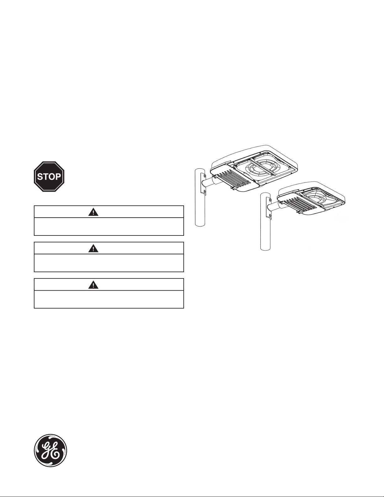
• This luminaire is designed for outdoor lighting service,
and should not be used in areas of limited ventilation,
or in high ambient temperatures.
• Best results will be obtained if installed and maintained
according to the following recommendations.
• Luminaire is designed to operate in ambient
temperatures ranging from -40°C to 50°C and to be
mounted horizontally to a vertical pole with LEDs
facing down, as shown.
SPECIFICATIONS
• Weight: Maximum weight <50 lbs (22.68 kg)
• EPA: 1.35 sq ft max (0.13 sq M) (Calculated using
1.30 Cd X Total Area of 1.04 ft2)
• IP Rating: Optical 65, Standard Electrical Enclosure:
UL 1598 Wet Location Rated
imagination at work
Page 2
UNPACKING
1
• This luminaire has been properly packed so that no
parts should have been damaged during transit.
• Inspect to conrm.
HANDLING
2
• Damage may occur if luminaire is improperly handled
outside of pack.
• Do not impact or stack luminaire after removal from
packaging.
MOUNTING
3
WARNING
Risk of injury or damage. Unit will fall if not installed
properly. Follow installation instructions.
Follow the appropriate installation instructions based on
your selected mounting method:
a. Sliptter Mounting
b. Round Pole Architectural Arm Mounting
c. Square Pole Architectural Arm Mounting
3a Sliptter Mounting
This luminaire has been congured specically to mount to a
2-inch pipe brackets (2-3/8” OD).
• Place xture against pole
• Install 3/8 bolt, lock washer and washer in top as
shown and tighten into nut plate
• Open arm door and install 3/8 bolt, lock washer and
washer inside arm as shown and tighten into nut
plate. (See Figure 3 and 4)
• Torque top and bottom bolts to 25 - 32 ft-lbs (34-43 N-m).
• Inspect installation to ensure xture is secure.
WARNING
Under no conditions should architectural arm mounting bolts
be torqued to greater than 32 ft-lbs.
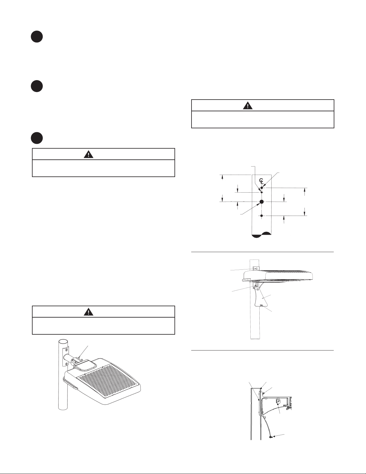
DRILLING TEMPLATE
ROUND POLE MOUNTING
3.5 to 4.5 inch (89 to 114mm) OD
round pole mounting arm.
.312 in. DIA.
(8 mm DIA.)
5.250 in.
(133 mm)
(MIN.)
1.812 in.
(46 mm)
.750 in. DIA.
(19 mm DIA.)
(HOLE)
FIGURE 2
(43 N-m)
.438 in. DIA.
(11 mm DIA.)
(2 PLACES)
2.719 in.
(69 mm)
5.438 in.
(138 mm)
• Hold luminaire approximately level with pipe. Pull
wires through arm and place slip tter over 2-inch
(51mm) pipe (2 3/8-inch (60mm) OD).
• Tighten the (4) sliptter 3/8 bolts to 10-14 ft-lbs
(14-19 N-m). Tighten jam nuts after bolts have been
tightened. (See Figure 1)
• Inspect installation to ensure xture is secure.
WARNING
Under no conditions should sliptter bolts be torqued to a
level greater than 14 foot pounds (19 N-m).
Sliptter 3/8 Bolts and Jam Nuts
FIGURE 1
3b Round Pole Architectural Arm Mounting
This luminaire has been congured specically to mount
to round pole 3.5-4.5 inches (89-114mm) in diameter. Hole
pattern on round pole shall be in accordance with Figure 2.
Torque Top Bolt
to 25-32 ft-lbs.
(34-43N-m)
Torque Bottom Bolt
to 25-32 ft-lbs.
(34-43N-m)
FIGURE 3
FIGURE 4
Door
Arm Door Screw
Section view: Round Pole Mounting
Architectural Arm with Door
Nut Plate
Pole
Bolt, Lock Washer,
Flat Washer
Terminal Board
Arm Door Screw
Page 3
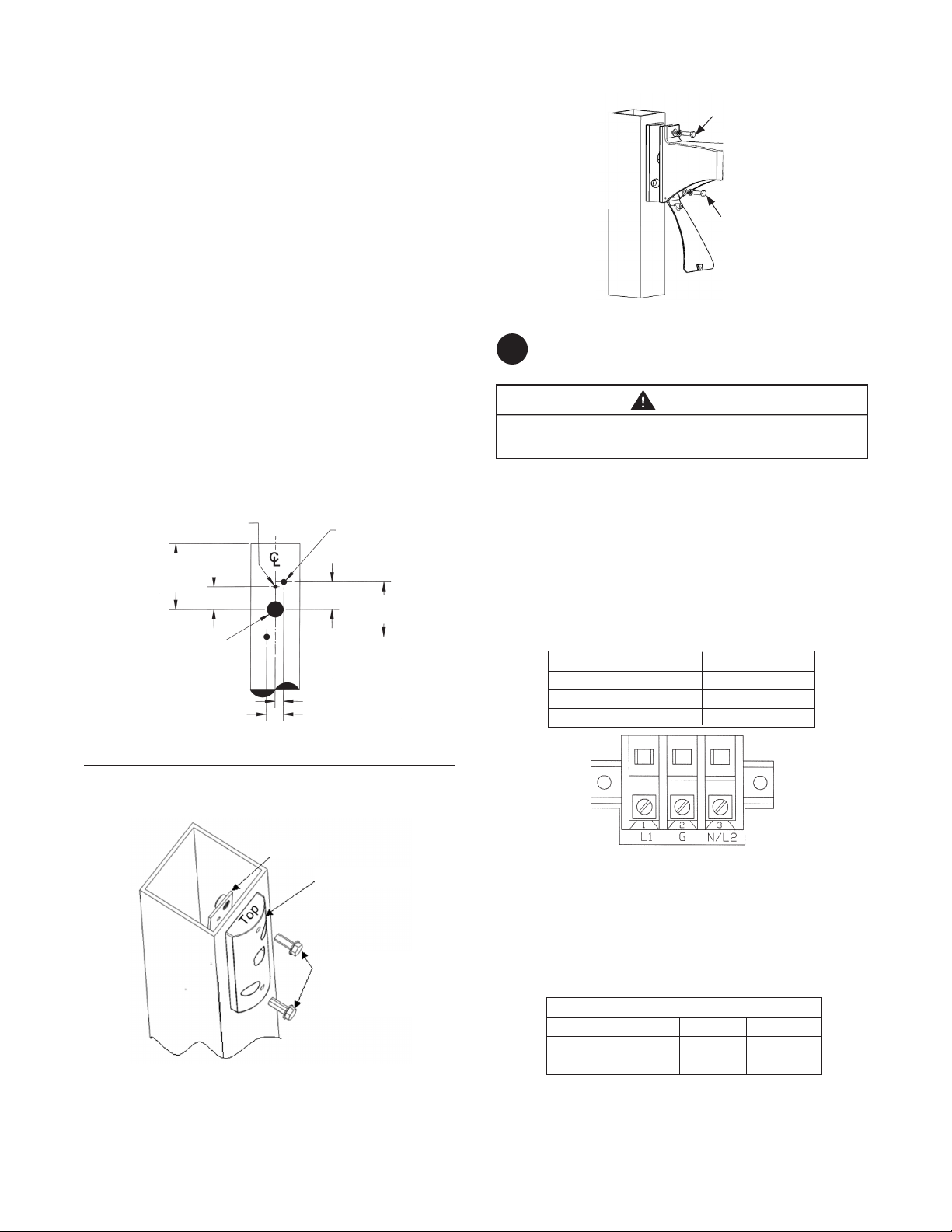
3c Square Pole Architectural Arm Mounting
This luminaire has been congured the same as 3b
and an adapter plate has been included to mount to
a square pole. Hole pattern on square pole shall be in
accordance with Figure 5.
• Orient adapter block so that the end marked top is in
the up position.
• With adapter block end oriented properly, mount
adapter block to pole with the nut plate and 3/8-16
bolts and washer supplied as shown. Torque 3/8-16
bolts to 25 - 32ft-lbs (34-43 N-m). (See Figure 6)
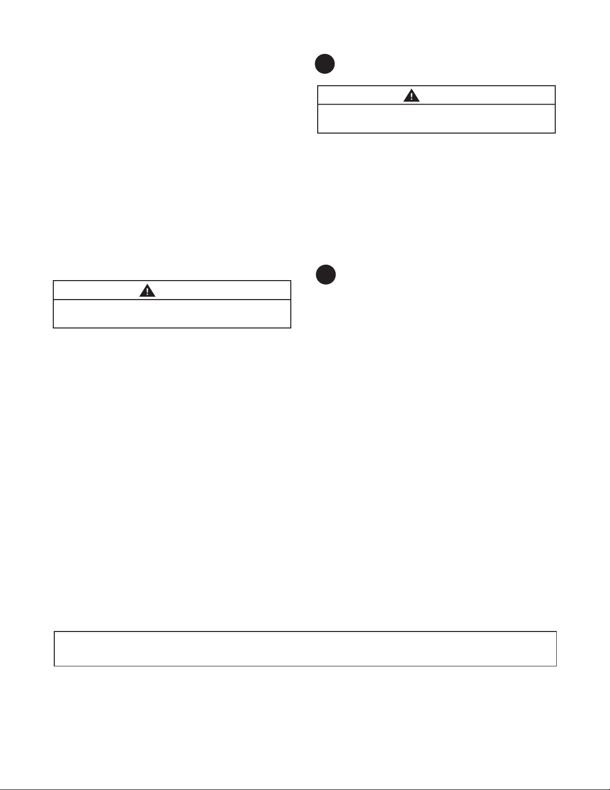
• Place xture against adapter block.
• In top location install 3/8-16 bolt through lock
washer, washer and mounting arm as shown.
(See Figure 7)
• Open arm door and Install 3/8 bolt into tapped hole
of adapter block. (See Figure 7)
• Torque top and bottom bolts to 25 - 32 ft-lbs (34-43 N-m).
• Inspect installation to ensure xture is secure.
FIXTURE ARM TO ARM ADAPTER
Torque Top Bolt
to 25 - 32 ft-lbs.
(34-43 N-m)
Torque Bottom Bolt
to 25 - 32 ft-lbs.
(34-43 N-m)
FIGURE 7
WIRING
4
CAUTION
Risk of Damage or Injury: Door should be closed with
screw until xture in nal location.
FIGURE 5
SQUARE POLE MOUNTING
.312 in. DIA.
(8 mm DIA.)
5.250 in.
(133 mm)
(MIN.)
1.812 in.
(46 mm)
1.250 in. DIA.
(32 mm DIA.)
(HOLE)
ADAPTER PLATE FOR
DRILLING TEMPLATE
2.196 in.
(56 mm)
.656 in. (17 mm)
1.312 in. (33 mm)
SQUARE POLE
Nut Plate
Adapter Block
.438 in. DIA.
(11 mm DIA.)
(2 PLACES)
4.392 in.
(112 mm)
• NOTE: Make all electrical connections in accordance
with the National Electrical Code and any applicable
local code requirements.
• Strain relief for incoming power must be provided in
the pole top by the customer.
• Supply Wire Type and Size, for Customer Connection
to Terminal Board: 16 AWG (1.5mm2) to 6 AWG
(10mm2) Solid or Stranded.
Terminal Board Connections:
Terminal Board Position Supply Type
L1 High Line
G Ground
N/L2 Low Line/Neutral
• NOTE: Verify that supply voltage is correct by
comparing it to nameplate inside door or on carton.
FIGURE 6
3/8-16 Washer and Bolts
Torque Bolts to 25 - 32ft-lbs.
(34-43 N-m)
External Dimming Control (If Applicable):
• Gray Lead = 0VDC (-)
• Violet Lead = Up To 10VDC (+)
Dimming Input/Output
Control Voltage1 Low (0V) High(7.5-10V)
Nominal Input Wattage2
Nominal Lumen Output
• 1 Linear Transition between Low and High
• 2 Component and system tolerance may aect the
end point levels and linearity of transition
20% of Max 100%
2
Page 4
PE
Dimming Control (If Applicable):
• No external connections for Dimming are required
when the GE Dimming PE Control and GE Dimming PE
Receptacle is used.
• All dimming control connections will be made
between the Dimming PE and Luminaire through the
included PE Receptacle.
• Refer to instructions included with GE Dimming PE
Control regarding appropriate settings for dimming
control.
PHOTOELECTRIC CONTROL:
• (If option present)—Photoelectric control receptacle
should be oriented before control is installed.
• Loosen the two holding screws and rotate receptacle
until “North” is directed as near as possible to true
North.
• Tighten holding screws and install control.
CAUTION
Ensure the PE socket base gasket is properly seated in the
die casting hole before tightening the holding screws.
SLIPFITTER MOUNTING:
• Connect Luminaire wire leads to supply wire.
• Connections are to be made in interior of pole.
• Replace pole cap. A wiring diagram is provided on a
label inside luminaire for reference.
• For sliptter units without leads, connections may be
made to terminal board inside xture.
• Note that care should be exercised not to pinch leads
between door and housing when closing the door.
MAINTENANCE / CLEANING
5
WARNING
Risk of electric shock. Make certain power is o before
attempting any maintenance.
• To maintain high optical eciency, occasional
cleaning of the outer lens surface may be needed,
with frequency dependent on local conditions.
• Use a mild soap or detergent, which is essentially
neutral pH (pH approximately 6 to 8), nonabrasive,
and which contains no chlorinated or aromatic
hydrocarbons.
• Wash thoroughly, using a soft cloth.
• Rinse with clean, cold water and wipe dry.
STORAGE
6
• Prior to installation, units should NOT be stored
outside in corrugated boxes (cardboard boxes) alone.
• Until installation, all units should be placed in a
covered dry storage area. The storage area should
not exceed -40°C (-40°F) to 50°C (122°F).
- This can be preferably in a roofed area or with a
tarp that is secured in such a way to keep water
o of the corrugated boxes (cardboard boxes).
ARM MOUNTINGS:
• Terminal Board is in the Architectural Mounting Arm.
• Open mounting arm door to gain access to terminal
board.
• Wire supply leads to terminal board in accordance
with labeling.
• Close door when wiring is complete.
These instructions do not purport to cover all details or variations in equipment nor to provide for every possible contingency to be met in
connection with installation, operation or maintenance. Should further information be desired or should particular problems arise which are not
covered suciently for the purchaser’s purposes, the matter should be referred to GE Lighting.
GE Lighting • 1-888-MY-GE-LED (1 - 888 - 69 - 43 - 533) • www.gelighting.com
GE Lighting is a subsidiary of the General Electric Company. Evolve and the GE brand and logo are trademarks of the General Electric Company.
© 2013 GE Lighting. Information provided is subject to change without notice. All values are design or typical values when measured under laboratory conditions.
g
35-201578-198 (Rev 09/17/13)
English
Page 5

GE
Lighting
Lampadaire à DEL Evolve
Systèmes d’installation Modulaires – Petit et Moyen
(EASM & EAMM)
Guide d’Installation
GEH-6006A
™
ARRÊT
AVANT DE COMMENCER
Lisez attentivement toutes ces instructions.
Conservez ces instructions pour référence future.
AVERTISSEMENT
Risque de choc électrique. Déconnectez l’alimentation
électrique avant d’installer ou réparer ce produit.
AVERTISSEMENT
Danger de blessure et de dommage matériel. L’appareil
tombera au sol s’il est mal installé. Suivez les instructions
d’installation.
ATTENTION
Danger de blessure. Lors de l’installation et de la réparation
de cet appareil, porter des lunettes et des gants de sécurité.
Cet appareil est conforme aux exigences de la partie 15 des règles
de la FCC. Son utilisation est sujette aux conditions suivantes : (1) cet
appareil ne doit pas causer d’interférences nuisibles; (2) cet appareil
doit accepter toutes les interférences reçues, y compris celles pouvant
causer un fonctionnement indésirable. Ce DEFR de la classe [ A ] est
conforme à la NMB-003 du Canada.
Remarque : Cet appareil a été testé et reconnu conforme aux
limites établies pour les appareils numériques de classe A, selon
la partie 15 des règles de la FCC. Ces limites sont conçues pour
assurer une protection raisonnable contre les interférences nuisibles
dans un environnement commercial. Cet appareil génère, utilise
et émet de l’énergie sous forme de radiofréquences, de sorte que
si son installation et son utilisation ne sont pas conformes à la
notice d’utilisation, il peut être la cause de parasites nuisibles aux
communications radio. L’utilisation de cet équipement dans une zone
résidentielle risque fort de causer des interférences nuisibles, auquel
cas l’utilisateur devra corriger le problème à ses propres frais.
• Ce lampadaire est conçu pour l’éclairage extérieur et ne
doit pas être utilisé dans des lieux à faible ventilation ou à
températures ambiantes élevées.
•
Les meilleurs résultats seront obtenus si l’installation et
l’entretien sont conformes aux recommandations suivantes.
•
Le lampadaire est conçu pour fonctionner à des tempéra tures allant de -40°C à 50°C et doit être installé horizontale ment à un poteau vertical avec les LED orientées vers le bas,
comme indiqué sur l’illustration.
SPÉCIFICATIONS
• Poids: Maximum <50 lbs (22.68 kg)
• EPA: 1.35 sq ft max (0.13 sq M2) (Calculé en utilisant 1.30 Cd
X Surface Totale de 1.04 pi2)
• Classication IP: Optique 65, Enceinte Électrique Standard:
UL 1598 Classication pour emplacements mouillés
imagination at work
Page 6

DÉBALLAGE
1
• Ce lampadaire et été emballé pour qu’aucune pièce ne soit
endommagée lors du transport.
• Inspecter pour conrmer.
MANIPULATION
2
• Des dégâts peuvent se produire si le lampadaire est
incorrectement manipulé au dehors de l’emballage.
• Ne pas iniger de choc au lampadaire et ne pas superposer
les lampadaires après déballage.
• Placer le gabarit contre le poteau
• Installer la vis de 3/8, la rondelle anti-retour et la rondelle
supérieure comme indiqué et serrer contre la plaque de l’écrou.
• Ouvrir la trappe d’accès du support et installer la vis de 3/8,
la rondelle anti-retour et la rondelle à l’intérieur du support
comme indiqué et serrer la plaque de l’écrou. (Voir Figure 3 et 4)
• Serrer les vis supérieures et inférieures à 25 -32 ft-lbs
(34-43 N-m).
• Inspecter pour s’assurer que l’installation est sûre.
AVERTISSEMENT
Les vis du bras de support ne doivent en aucune circonstance
être serrées au-delà de 32 ft-lbs. (43 N-m)
MOUNTING
3
AVERTISSEMENT
Risque de blessure ou de dégât. L’unité risque de tomber
si l’installation n’est pas eectuée correctement. Suivre les
instructions d’installation.
Choisir les instructions adaptées à la méthode d’installation :
a. Installation par encastrement
b. Installation par support sur poteau à section circulaire
c. Installation par support sur poteau à section carrée.
3a Installation par encastrement
Ce lampadaire a été conguré spécialement pour être installé sur
des supports de conduits de 2 inch de diamètre (2-3/8” de diamètre
extérieur).
• Maintenir le lampadaire à niveau avec le conduit. Tirer les
ls au travers du bras et placer la bague d’encastrement sur
le conduit de 2-inch (51 mm) (2 3/8-inch (60 mm) diamètre
extérieur).
• Serrer les (4) vis de 3/8 en utilisant un couple de serrage de
10-14 ft-lbs (14-19 N-m). Serrer les contre-écrous après le
serrage des vis (voir Figure 1)
• Inspecter pour s’assurer que l’installation est sûre.
AVERTISSEMENT
Les vis du bras de support ne doivent en aucunes
circonstances être serrées au-delà de 14 ft-lbs. (19 N-m)
Bras de support pour poteau à section circulaire de
3,5 à 4,5 inch (89 à 114 mm) de diamètre extérieur
5.250 in.
(133 mm)
(MIN.)
.750 in. DIA.
(19 mm DIA.)
(PERÇAGE)
FIGURE 2
Serrer les vis du
haut à 25-32 ftlbs.
(34-43 N-m)
Serrer les vis du bas
à 25-32 ft-lbs. (34-43
N-m)
SCHÉMA DE PERÇAGE
INSTALLATION SUR POTEAU À
SECTION CIRCULAIRE
.312 in. DIA.
(8 mm DIA.)
1.812 in.
(46 mm)
.438 in. DIA.
(11 mm DIA.)
(2 PLACES)
2.719 in.
(69 mm)
Trappe
Vis de la trappe
5.438 in.
(138 mm)
Vis d’encastrement de 3/8 et contre-écrous
FIGURE 1
3b Installation par support sur poteau à section
circulaire
Ce lampadaire a été spécialement conguré pour être installé sur
un poteau à section circulaire de 3,5-4,5 inches (89-114 mm) de
diamètre. L’arrangement des trous de xation doit être conforme
à la Figure 2.
FIGURE 3
FIGURE 4
Section: Poteau à section circulaire
avec bras architectural et trappe
Plaque de serrage
des écrous
Poteau
Vis, rondelle anti-retour,
Rondelle plate
Borne Électrique
Vis de la trappe
Page 7

3c Installation par support sur poteau à section
carrée
Ce lampadaire a été conguré de la même manière que 3b
et une plaque intermédiaire a été incluse pour installation sur
poteau à section carrée. L’arrangement des trous de xation
sur poteau à section carrée doit être conforme à la Figure 5.
• Orienter le bloc intermédiaire tel que l’extrémité identiée par
l’inscription ‘haut’ est en position haute.
• Avec le bloc intermédiaire orienté de manière correcte,
installer le bloc intermédiaire sur le poteau à l’aide de la
plaque de serrage des écrous et les vis de 3/8-16 et la ron delle fournie comme indiqué. Serrer les vis de 3/8-16 à 25
- 32 ft-lbs (34-43 N-m). (Voir la Figure 6)
• Placer le gabarit contre le bloc intermédiaire.
• A l’emplacement supérieur, installer une vis 3/8-16 au travers
de la rondelle anti-retour, la rondelle et le bras de xation
comme indiqué (voir Figure 7)
• Ouvrir la trappe d’accès du support et installer une vis 3/8
dans le letage du bloc intermédiaire. (Voir Figure 7)
• Serrer les vis supérieures et inférieures à 25 -32 ft-lbs
(34-43 N-m).
• Inspecter pour s’assurer que le gabarit est bien installé.
GABARIT ET SUPPORT INTERMÉDIAIRE
Serrer la vis du haut à
25 - 32 ft-lbs. (34-43 N-m)
Serrer la vis du bas
à 25 - 32 ft-lbs. (3443 N-m)
FIGURE 7
CABLAGE
4
MISE EN GARDE
Risque de dégât ou de blessure : La trappe doit être
fermée à l’aide d’une vis tant que le gabarit n’est pas en
position dénitive.
FIGURE 5
FIGURE 6
SCHÉMA DE PERCAGE INSTALLATION
SUR POTEAU À SECTION CARRÉE
.312 in. DIA.
(8 mm DIA.)
5.250 in.
(133 mm)
(MIN.)
1.812 in.
(46 mm)
1.250 in. DIA.
(32 mm DIA.)
(PERÇAGE)
PLAQUE INTERMÉDIAIRE POUR
POTEAU À SECTION CARRÉE
Plaque de serrage des écrous
2.196 in.
(56 mm)
.656 in. (17 mm)
1.312 in. (33 mm)
Bloc intermédiaire
Rondelle et vis 3/8-16
Serrer les vis a 25-32ft-lbs.
(34-43 N-m)
.438 in. DIA.
(11 mm DIA.)
(2 PLACES)
4.392 in.
(112 mm)
• REMARQUE: Eectuer toutes les connections électriques
en accord avec le National Electrical Code et les exigences
locale applicables.
• Le client doit fournir le réducteur de tension pour
l’alimentation électrique, placé en haut du poteau.
• Fournir au client le type de câble et la taille pour connexion
à la borne électrique : de 16 AWG (1.5 mm2) à 6 AWG
(10mm2) Fil unique ou multiple.
Connexions de la borne électrique:
Position au bornier Câblage
L1 Secteur
G Terre
N/L2 Neutre
• REMARQUE: Vérier que la tension d’alimentation est
correcte en la comparant à la plaque signalétique placée à
l’intérieur de la trappe ou sur le carton.
GRADATEUR EXTERNE (SI APPLICABLE) :
• Fil gris = 0 V c.c. (-)
• Fil violet = Jusqu’à 10 V c.c. (+)
Gradation, entrée/sortie
Tension de commande1 Basse (0 V) Élevée (7,5-10 V)
Puissance nominale d’entrée
Sortie nominale en lumens
2
20% of Max 100%
2
• 1 Transition linéaire entre basse et élevée
• 2 La tolérance des composants et du système peuvent
aecter les niveaux de point nal et la linéarité de
la transition
Page 8

GRADATEUR PHOTOÉLECTRIQUE (SI APPLICABLE) :
• Aucune connexion externe de gradation n’est
nécessaire lorsque la commande de gradateur PE
et le réceptacle de gradateur PE de GE sont utilisés.
• Toutes les connexions de commande de gradation
seront réalisées entre le gradateur PE et le luminaire
via le réceptacle PE inclus.
• Lire les instructions incluses avec la commande de
gradateur PE de GE concernant les réglages
appropriés de la commande de gradateur.
COMMANDE PHOTOÉLECTRIQUE :
• (Si l’option est choisie) Le réceptacle de la commande
peut être orienté avant d’installer la commande.
• Desserrez les deux vis de retenue et faites tourner
le réceptacle jusqu’à ce que l’inscription « North »
soit orientée le plus près possible du nord véritable.
• Serrez les vis de retenue et installez la commande.
ATTENTION
Assurez-vous que le joint de la base de douille est
correctement enfoncé dans le trou du réceptacle moulé
avant de serrer les vis de retenue.
MONTAGE SUR JOINT COULISSANT :
• Connectez les ls conducteurs du luminaire au câble
d’alimentation.
• Les connexions doivent être faites à l’intérieur du
poteau.
• Réinstallez le capuchon du poteau. Un schéma de
câblage gure sur une étiquette à l’intérieur du
luminaire pour référence.
• Si vous utilisez un joint coulissant sans ls
conducteurs, les connexions peuvent être faites sur la
plaque de connexions à l’intérieur du luminaire.
• Faites attention de ne pas pincer les ls entre le volet
et le boîtier lorsque vous fermez le volet.
ENTRETIEN / NETTOYAGE
5
AVERTISSEMENT
Risque de choc électrique. Avant de commencer toute
opération d’entretien, assurez-vous que l’alimentation électrique est coupée.
• Pour conserver l’ecacité du module optique,
nettoyez périodiquement la surface extérieure de la
lentille (la fréquence des nettoyages dépendra des
conditions locales).
• Utilisez un savon doux ou un détergent essentielle
ment neutre (ayant un pH d’environ 6 à 8), sans
abrasif et sans hydrocarbure chloré ou aromatique.
• Lavez à fond avec la solution de nettoyage en
utilisant un chion doux.
• Rincez avec de l’eau froide et propre, puis essuyez.
STOCKAGE
6
• Avant l’installation, les unités ne doivent PAS être stockées à
l’extérieur dans des emballages de carton.
• Jusqu’à l’installation, toutes les unités doivent être placées
dans un local couvert et sec. L’espace de stockage ne doit
pas excéder -40 °C (-40 °F) à 50 °C (122 °F).
– Ceci peut être dans un local couvert ou sous une bâche
attachée de manière à protéger les emballages de la
pluie/l’eau.
MONTAGE SUR BRAS :
• La plaque de connexions est située dans le bras
architectural.
• Ouvrez le volet du bras de montage an de pouvoir
accéder à la plaque de connexions.
• Faites passer les ls conducteurs sur la plaque de
connexions, conformément à l’étiquette.
• Lorsque le câblage est terminé, fermez le volet.
Ces instructions n’ont pas pour but de couvrir tous les détails et toutes les variantes de l’équipement, ni de répondre à tous les impondérables
possibles en relation avec l’installation, le fonctionnement et l’entretien. Si vous désirez plus d’informations ou si des problèmes particuliers
surviennent qui ne sont pas couverts susamment pour les besoins de l’acheteur, le sujet doit être soumis à GE Lighting.
GE Lighting • 1-888-MY-GE-LED (1 - 888 - 69 - 43 - 533) • www.gelighting.com
GE Lighting est une liale de la General Electric Company. Evolve ainsi que la marque et le logo GE sont des marques commerciales déposées de la General Electric Company.
© 2013 GE Lighting. Les informations fournies ici sont susceptibles de changer sans préavis. Toutes les données sont des valeurs de conception ou caractéristiques lors de leur
g
mesure en conditions de laboratoire.
35-201578-198 (Rev 09/17/13)
French
Page 9

GE
Guía de instalación
GEH-6006A
Lighting
Lámpara de LEDs para áreas Evolve
Lámparas modulares - pequeñas y medianas (EASM y EAMM)
ANTES DE COMENZAR
Lea estas instrucciones completamente y cuidadosamente.
Guarde estas instrucciones para uso futuro.
ADVERTENCIA
™
Riesgo de descarga eléctrica. Desconecte la energía antes de
suministrar servicio de mantenimiento o instalar el producto.
ADVERTENCIA
Riesgo de lesiones o daño. La unidad fallará si no se instala apro-
piadamente. Siga las instrucciones de instalación.
PRECAUCIÓN
Riesgo de lesiones. Utilice gafas de seguridad y guantes durante la
instalación y mantenimiento.
Este dispositivo cumple con la Parte 15 de las Reglas de la FCC.
La operación está sujeta a las dos condiciones siguientes: (1) este
dispositivo no puede causar interferencia perjudicial, y (2) este
dispositivo debe aceptar cualquier interferencia recibida, incluida
la interferencia que pueda causar una operación no deseada. Este
Dispositivo de iluminación de radiofrecuencia (RFLD) de Clase [A]
cumple con la norma canadiense ICES-003.
Nota: este equipo ha sido probado y se ha determinado que cumple
con los límites de un dispositivo digital Clase A, de conformidad con
la Parte 15 de las Reglas de la FCC. Estos límites están diseñados
para proporcionar una protección razonable contra la interferencia
perjudicial cuando el equipo se opera en un entorno comercial. Este
equipo genera, usa y puede irradiar energía de radiofrecuencia y, si
no se instala y usa de acuerdo con el manual de instrucciones, puede
causar interferencia perjudicial a las radiocomunicaciones.
La operación de este equipo en un área residencial puede causar
interferencia perjudicial, en cuyo caso el usuario deberá corregir la
interferencia a su propia costa.
• Esta lámpara está diseñada para servicio de iluminación
en exteriores, y no debe utilizarse en áreas con ventilación
limitada, o en temperaturas ambiente altas.
• Se obtendrán los mejores resultados si se instala y recibe
mantenimiento según las siguientes recomendaciones.
• La lámpara está diseñada para funcionar a temperaturas
ambiente que varían desde -40°C a 50°C y para montarse
horizontalmente en un poste vertical con las bombillas LEDs
dirigidas hacia abajo, según se muestra.
ESPECIFICACIONES
• Peso: Peso máximo <50 lbs (22.68 kg)
• Área Proyectada Efectiva: 1.35 pie2 máx (0.13 m2) (calculada
utilizando 1.30 Bujías X área total de 1.04 pie2)
• Clasicación IP (Ingress Protected): Óptico 65, Carcasa están-
dar para componentes eléctricos:
• Clasicada para lugares mojados según UL 1598
imagination at work
Page 10

DESEMPAQUE
1
• Esta lámpara ha sido empacada apropiadamente de modo
que las piezas no deberían sufrir daño durante el transporte.
• Inspeccione para conrmar.
MANIPULACIÓN
2
• Podría ocurrir daño si la lámpara se manipula inapropiadamente fuera del paquete.
• No golpee ni apile la lámpara después de sacarla del embalaje/paquete.
MONTAJE
3
ADVERTENCIA
Riesgo de lesiones o daño. La unidad fallará si no se instala apro-
piadamente. Siga las instrucciones de instalación.
Siga las instrucciones de instalación apropiadas según su método de
montaje seleccionado:
a. Montaje con ajustador deslizante
b. Montaje con brazo arquitectónico en poste redondo
c. Montaje con brazo arquitectónico en poste cuadrado
3a Montaje con ajustador deslizante
Esta lámpara ha sido congurada especícamente para montaje en
abrazaderas para tubo de 2 pulgadas (2-3/8” de Diámetro Exterior).
• Coloque la lámpara contra el poste
• Instale el perno de 3/8, la arandela de seguridad y la arandela
encima según se muestra, y apriete en la tuerca tipo placa
• Abra la puerta del brazo e instale el perno de 3/8, la arandela
de seguridad y la arandela en el interior del brazo según se
muestra, y apriete en la tuerca tipo placa (Vea la Figura 3 y 4).
• Apriete los pernos superior e inferior hasta 25 a 32 lbs-pie
(34 a 43 N-m)
• Inspeccione la instalación para garantizar que la lámpara
está segura.
ADVERTENCIA
Bajo ninguna circunstancia, los pernos de montaje del brazo
arquitectónico deben apretarse hasta un valor superior a 32
libras-pie. (43 N-m)
PLANTILLA DE TALADRADO
MONTAJE EN POSTE REDONDO
Brazo de montaje en poste redondo de 3,5 a
4,5 pulgadas (89 a 114mm) de Diámetro Exterior.
FIGURA 2
0,312 pulg. DIÁM.
(8 mm DIÁM.)
5,250 pulg.
(133 mm)
(MÍN)
1,812 pulg.
(46 mm)
0,750 pulg. DIÁM.
(19 mm DIÁM.)
(ORIFICIO)
0,438 pulg. DIÁM.
(11 mm DIÁM.)
(2 LUGARES)
2,719 pulg.
(69 mm)
5,438 pulg.
(138 mm)
• Sostenga la lámpara aproximadamente a nivel con el tubo.
Hale los alambres a través del brazo y coloque el ajustador
deslizante sobre el tubo de 2 pulgadas (51mm) [2-3/8 pulgadas (60mm) de Diámetro Exterior].
• Apriete los (4) pernos de 3/8 del ajustador deslizante hasta 10
a 14 lbs-pie (14 a 19 N-m). Apriete las contratuercas después
de haber apretado los pernos. (Vea la Figura 1)
• Inspeccione la instalación para garantizar que la lámpara
está segura.
ADVERTENCIA
Bajo ninguna circunstancia, los pernos del ajustador deslizante
deben apretarse hasta un valor superior a 14 libras-pie (19 N-m)
Pernos de 3/8 del ajustador deslizante
y contratuercas
FIGURA 1
3b Montaje con brazo arquitectónico en poste
redondo
Esta lámpara ha sido congurada especícamente para montarse
en poste redondo de 3.5 a 4.5 pulgadas (89 a 114mm) de diámetro.
El patrón de oricios en el poste redondo deberá estar de acuerdo
con la Figura 2.
Apriete el perno
superior hasta 25
a 32 lbs-pie.
(34 a 43N-m)
Apriete el perno
inferior hasta 25 a 32
FIGURA 3
FIGURA 4
lbs-pie.
(34 a 43N-m)
Tuerca tipo placa
Puerta
Tornillo de la
puerta del brazo
Vista en sección: Brazo arquitectónico (con
puerta) de montaje en poste redondo
Poste
Perno, arandela de seguridad,
arandela plana
Placa de terminales
Tornillo de la puerta
del brazo
Page 11

3c Montaje con brazo arquitectónico en poste
cuadrado
Esta lámpara tiene la misma conguración del montaje 3b y se
incluye una placa adaptadora para montaje en poste cuadrado.
El patrón de oricios en el poste cuadrado deberá estar de acuerdo con la Figura 5.
• Oriente la placa adaptadora de modo que la parte superior
marcada como extremo (“end”) esté en la posición arriba.
• Con el extremo de la placa adaptadora orientada apropia-
damente, monte la placa adaptadora al poste con la tuerca
tipo placa y los pernos de 3/8-16 y la arandela suministrados,
según se muestra. Apriete los pernos de 3/8-16 hasta 25 a
32 lbs-pie (34 a 43 N-m) (Vea la Figura 6)
• Coloque la lámpara contra la placa adaptadora.
• En la ubicación superior, instale el perno de 3/8-16 a través de
la arandela de seguridad, la arandela y el brazo de montaje,
según se muestra. (Vea la Figura 7)
• Abra la puerta del brazo e instale el perno de 3/8 dentro del
roscado de la placa adaptada. (Vea la Figura 7)
• Apriete los pernos superior e inferior hasta 25 a 32 lbs-pie
(34 a 43 N-m)
• Inspeccione la instalación para garantizar que la lámpara está
segura.
PLANTILLA DE TALADRADO
MONTAJE EN POSTE CUADRADO
FIGURA 5
0,312 pulg. DIÁM.
(8 mm DIÁM.)
5,250 pulg.
(133 mm)
(MÍN)
1,812 pulg.
(46 mm)
1,250 pulg. DIÁM.
(32 mm DIÁM.)
(ORIFICIO)
0,438 pulg. DIÁM.
(11 mm DIÁM.)
(2 LUGARES)
2,196 pulg.
(56 mm)
0,656 pulg. (17 mm)
1,312 pulg. (33 mm)
4,392 pulg.
(112 mm)
BRAZO DE LÁMPARA A PLACA ADAPTADORA
Apriete el perno superior
hasta 25 a 32 lbs-pie.
(34 a 43 N-m)
Apriete el perno inferior
hasta 25 a 32 lbs-pie.
(34 a 43 N-m)
FIGURA 7
CABLEADO
4
PRECAUCIÓN
Riesgo de daño o lesiones: La puerta debe estar cerrada con el
tornillo hasta que la lámpara esté en la ubicación nal.
• NOTA: Realice todas las conexiones eléctricas de acuerdo con
el Código Eléctrico Nacional y cualquier requisito aplicable del
código local.
• Debe suministrarse un elemento de alivio de esfuerzo
mecánico para el cable de energía entrante en la parte superior del poste por parte del cliente.
• Suministre el tipo y tamaño de cable, para la Conexión del
Cliente con la placa de terminales: 16 AWG (1.5mm2) a 6 AWG
(10mm2) macizo o trenzado.
Conexiones de la placa de terminales:
Posición en la placa de terminales Tipo de suministro
L1 Línea de alta
G Conexión a tierra
N/L2 Línea de baja/Neutra
FIGURA 6
PLACA ADAPTADORA PARA
POSTE CUADRADO
Tuerca tipo placa
Placa adaptadora
Arandela y pernos de 3/8-16
Apriete los pernos hasta 25 a
32 lbs-pie.
(34 a 43 N-m)
• NOTA: Verique que el voltaje de suministro es correcto
comparándolo con el voltaje mostrado en la placa de datos
ubicada en el lado interior de la puerta o en la caja de cartón.
Control externo de atenuación (si es aplicable):
• Cable de conexión gris = 0 V CC (-)
• Cable de conexión violeta = hasta 10 V CC (+)
Entrada/salida de atenuación
Tensión de control1 Baja (0 V) Alta(7.5-10 V)
Potencia de entrada nominal (watts)
Potencia luminosa nominal (lumens)
• 1 Transición lineal entre Alta y Baja
• 2 Las tolerancias de los componentes y del sistema
pueden afectar los niveles extremos y la linealidad
de la transición
2
20% de la máx 100%
2
Page 12

Control fotoeléctrico (PE) de atenuación
(si es aplicable):
• Cuando se utiliza el Control de atenuación PE de GE y el
Receptáculo de atenuación PE de GE, no se necesitan
conexiones externas para atenuación.
• Todas las conexiones de control de atenuación se harán
entre el Control PE de atenuación y la luminaria, a través del
Receptáculo de atenuación PE incluido.
• Para ver los ajustes apropiados del control de atenuación,
consulte las instrucciones incluidas con el Control de atenu
ación PE de GE.
CONTROL FOTOELÉCTRICO:
• (Si la opción está presente): el receptáculo de control
fotoeléctrico debe orientarse antes de instalar el control.
• Aoje los dos tornillos de jación y gire el receptáculo hasta
dirigir ‘Norte’ hacia el norte verdadero con la mayor
aproximación posible.
• Apriete los tornillos de jación e instale el control.
PRECAUCIÓN
Asegúrese de que la junta de la base del zócalo PE esté correctamente asentada en el agujero de la pieza fundida antes de
apretar los tornillos de jación.
MONTAJE CON POSICIONADOR DESLIZANTE:
• Conecte los cables de conexión de la luminaria al cable de
alimentación.
• Las conexiones deben hacerse en el interior del poste.
• Vuelva a colocar la tapa del poste. En la etiqueta que está
dentro de la luminaria se proporciona un diagrama de
conexionado como referencia.
• Para unidades con posicionador deslizante sin cables de
conexión, las conexiones pueden hacerse a la tira de
terminales que está dentro del artefacto.
• Tenga cuidado para no pinzar cables de conexión entre la
puerta y el alojamiento cuando cierre la puerta.
MANTENIMIENTO / LIMPIEZA
5
ADVERTENCIA
Riesgo de choque eléctrico. Asegúrese de que la alimentación
eléctrica esté desconectada antes de realizar cualquier tarea de
mantenimiento.
• Para mantener una alta eciencia óptica puede ser
necesaria una limpieza ocasional de la supercie del lente
externo, con una frecuencia que depende de las
condiciones locales.
• Utilice un jabón o detergente suave, con pH esencialmente
neutro (pH comprendido entre 6 y 8 aprox.), no abrasivo, y
que no contenga hidrocarburos clorados ni aromáticos.
• Lave bien a fondo con un paño suave.
• Enjuague con agua fría limpia y seque.
ALMACENAMIENTO
6
• Antes de la instalación, las unidades NO se deben
almacenar en exteriores en cajas de cartón corrugado
únicamente.
• Hasta el momento de la instalación, todas las unidades
deben colocarse en un área de almacenamiento seca y
cubierta. El área de almacenamiento debe tener una
temperatura comprendida entre -40 °C (-40 °F) y
50 °C (122 °F).
- Esto debe tener lugar preferiblemente en un área
techada o con un toldo sujeto de forma tal que evite la
llegada de agua a las cajas de cartón corrugado.
MONTAJES DE BRAZOS:
• La tira de terminales está en el brazo de montaje
arquitectónico.
• Abra la puerta del brazo de montaje para tener acceso
a la tira de terminales.
• Conecte los cables de alimentación eléctrica a la tira
de terminales de acuerdo con la etiqueta.
• Una vez nalizado el cableado, cierre la puerta.
Estas instrucciones no pretenden cubrir todos los detalles o variaciones en los equipos, ni contemplar toda posible contingencia a encontrar en
relación con la instalación, operación o mantenimiento. Si se deseara información adicional o surgiera algún problema especíco que no esté
sucientemente tratado aquí para los propósitos del comprador, debe consultarse a GE Lighting.
GE Lighting • 1-888-MY-GE-LED (1 - 888 - 69 - 43 - 533) • www.gelighting.com
GE Lighting es una lial de General Electric Company. Evolve y la marca y logo GE son marcas registradas de General Electric Company.
© 2013 GE Lighting. La información suministrada está sujeta a cambios sin aviso previo. Todos los valores son valores típicos o de diseño,
g
medidos en condiciones de laboratorio.
35-201578-198 (Rev 09/17/13)
Spanish
 Loading...