

Page 1
GE
Lighting
™
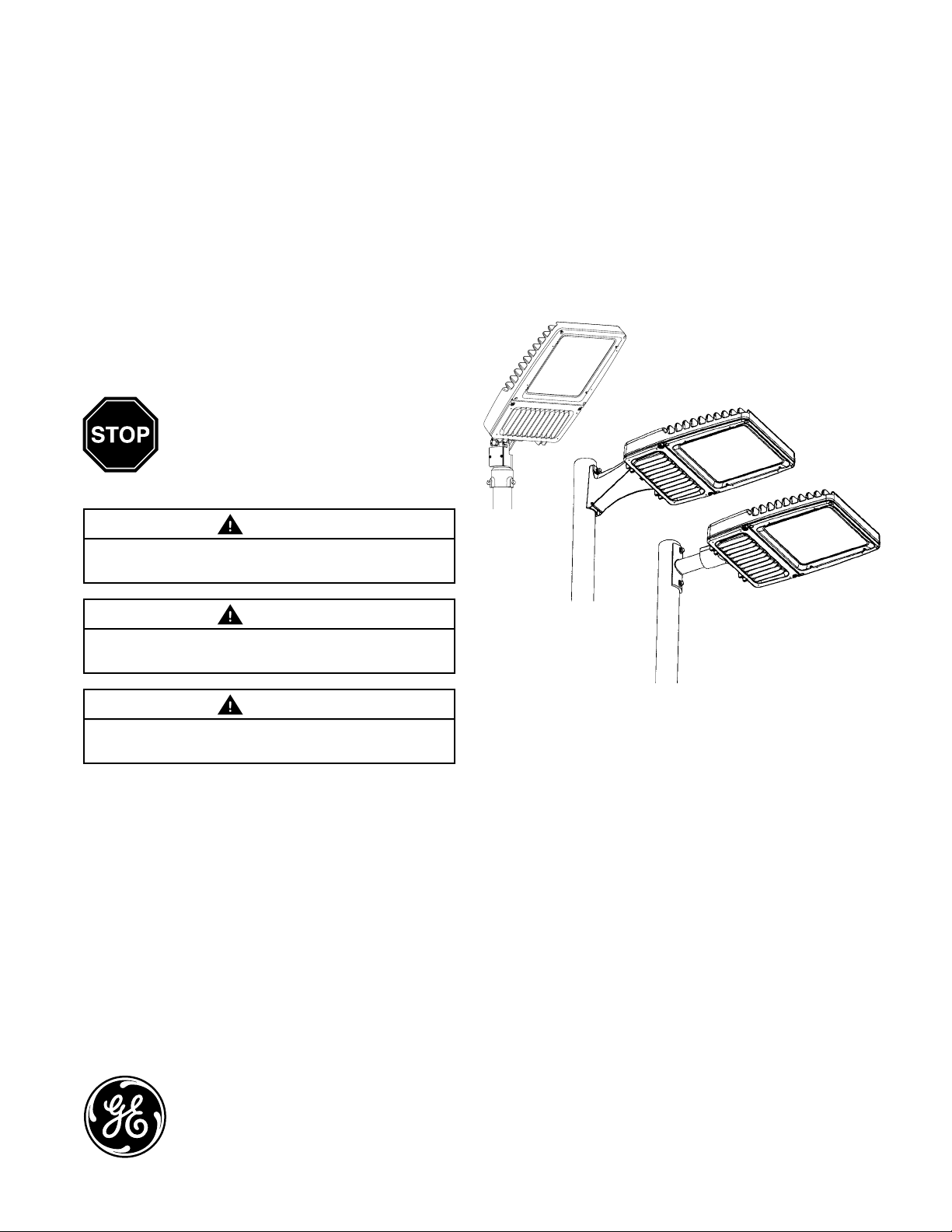
Evolve
Scalable Fixture (EAS)
BEFORE YOU BEGIN
Read these instructions completely and
carefully.
Save these instructions for future use.
LED Area Light
WARNING
Installation Guide
GEH-6016B
Risk of electrical shock. Disconnect power before servicing
or installing product.
WARNING
Risk of injury or damage. Unit will fall if not installed
properly. Follow installation instructions.
CAUTION
Risk of injury. Wear safety glasses and gloves during
installation and servicing.
This device complies with Part 15 of the FCC Rules. Operation is
subject to the following two conditions: (1) This device may not cause
harmful interference, and (2) this device must accept any interference
received, including interference that may cause undesired operation.
This Class [A] RFLD complies with the Canadian standard ICES-003.
Ce DEFR de la classe [ A ] est conforme à la NMB-003 du Canada.
Note: This equipment has been tested and found to comply with the
limits for a Class A digital device, pursuant to part 15 of the FCC Rules.
These limits are designed to provide reasonable protection against
harmful interference when the equipment is operated in a commercial
environment. This equipment generates, uses, and can radiate radio
frequency energy and, if not installed and used in accordance with
the instruction manual, may cause harmful interference to radio
communications. Operation of this equipment in a residential area
is likely to cause harmful interference in which case the user will be
required to correct the interference at his own expense.
• This luminaire is designed for outdoor lighting service,
and should not be used in areas of limited ventilation,
or in high ambient temperatures.
• Best results will be obtained if installed and maintained
according to the following recommendations.
• Luminaire is designed to operate in ambient
temperatures ranging from -40°C to 50°C
(-40°C to 35°C for >400W) and to be mounted
horizontally to a vertical pole with LEDs facing down,
or aimed up to 45° upward with a Knuckle slip fitter.
SPECIFICATIONS
• Weight: Maximum weight <50 lbs (22.68 kg)
• EPA: Horizontal mounting: 0.97 sq ft max (0.09 sq M)
45° mounting: 1.97 sq ft max (0.18 sq M)
• IP Rating: Optical 65, Standard Electrical Enclosure:
UL 1598 Wet Location Rated
imagination at work
Page 2
UNPACKING
1
• This luminaire has been properly packed so that no
parts should have been damaged during transit.
• Inspect to confirm.
HANDLING
2
• Damage may occur if luminaire is improperly handled
outside of pack.
• Do not impact or stack luminaire after removal from
packaging.
MOUNTING
3
WARNING
Risk of injury or damage. Unit will fall if not installed
properly. Follow installation instructions.
Follow the appropriate installation instructions based on
your selected mounting method:
a. Slipfitter Mounting
b. Round Pole Architectural Arm Mounting
c. Square Pole Architectural Arm Mounting
d. Knuckle Slipfitter for 2 3/8 in. (60mm) OD Tenon (0 to 45°
vertical aiming angle)
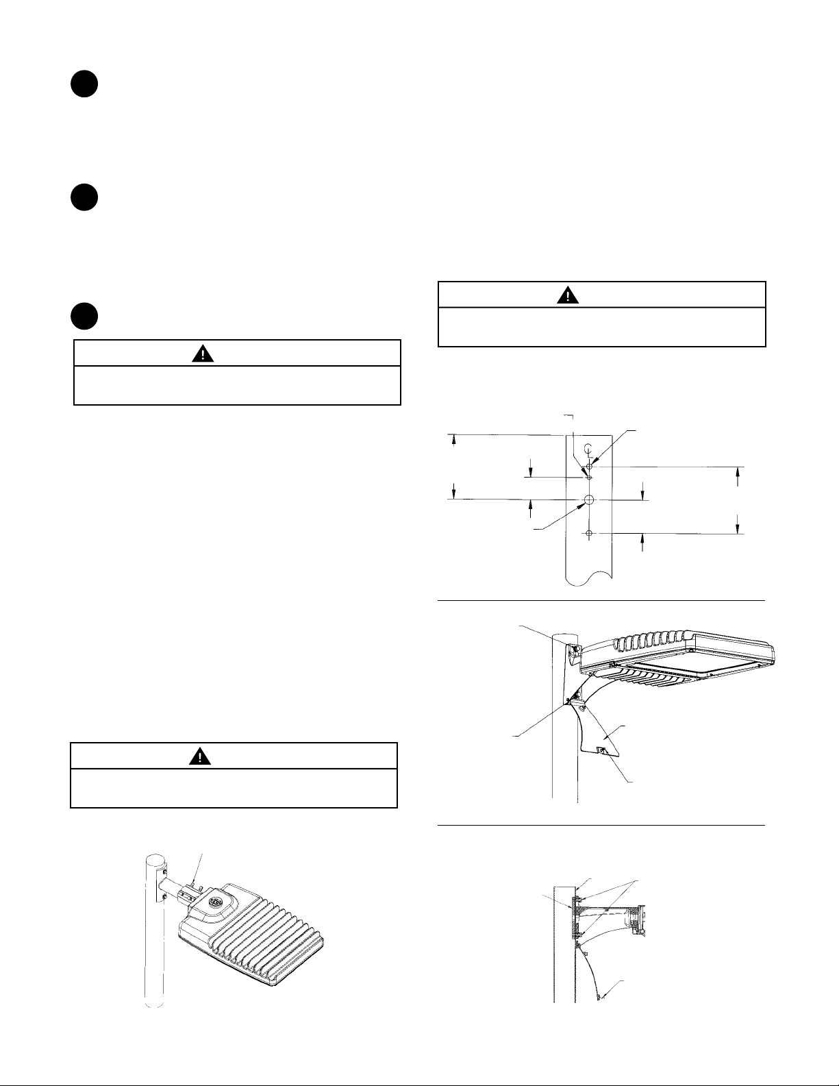
3a Slipfitter Mounting
This luminaire has been configured specifically to mount to a
2-inch pipe brackets (2-3/8” OD).
3b Round Pole Architectural Arm Mounting
This luminaire has been configured specifically to mount
to round pole 3.5-4.5 inches (89-114mm) in diameter. Hole
pattern on round pole shall be in accordance with Figure 2.
• Place fixture against pole.
• Install 3/8 bolt, lock washer and washer in top as
shown and tighten into nut plate.
• Open arm door and install 3/8 bolt, lock washer and
washer inside arm as shown and tighten into nut
plate. (See Figure 3 and 4)
• Torque top and bottom bolts to 25 - 32 ft-lbs (34-43 N-m).
• Inspect installation to ensure fixture is secure.
WARNING
Under no conditions should architectural arm mounting bolts
be torqued to greater than 32 ft-lbs.
DRILLING TEMPLATE
ROUND POLE MOUNTING
3.5 to 4.5 inch (89 to 114mm) OD
round pole mounting arm.
.312 in. DIA.
(8 mm DIA.)
5.2500 in.
(133 mm)
(MIN.)
(19 mm DIA.)
FIGURE 2
.750 in. DIA.
(HOLE)
1.8120 in.
(46 mm)
(43 N-m)
.438 in. DIA.
(11 mm DIA.)
(2 PLACES)
2.7190 in.
(69 mm)
5.4380 in.
(138 mm)
• Hold luminaire approximately level with pipe. Pull
wires through arm and place slip fitter over 2-inch
(51mm) pipe (2 3/8-inch (60mm) OD).
• Tighten the (4) slipfitter 3/8 bolts to 10-14 ft-lbs
(14-19 N-m). Tighten jam nuts after bolts have been
tightened. (See Figure 1)
• Inspect installation to ensure fixture is secure.
WARNING
Under no conditions should slipfitter bolts be torqued to a
level greater than 14 foot pounds (19 N-m).
Slipfitter 3/8 Bolts and Jam Nuts
FIGURE 1
Torque Top Bolt
to 25-32 ft-lbs.
(34-43N-m)
Torque Bottom Bolt
to 25-32 ft-lbs.
(34-43N-m)
FIGURE 3
FIGURE 4
Section view: Round Pole Mounting
Architectural Arm with Door
Pole
Nut Plate
Door
Arm Door Screw
Bolt, Lock Washer,
Flat Washer
Arm Door Screw
Page 3
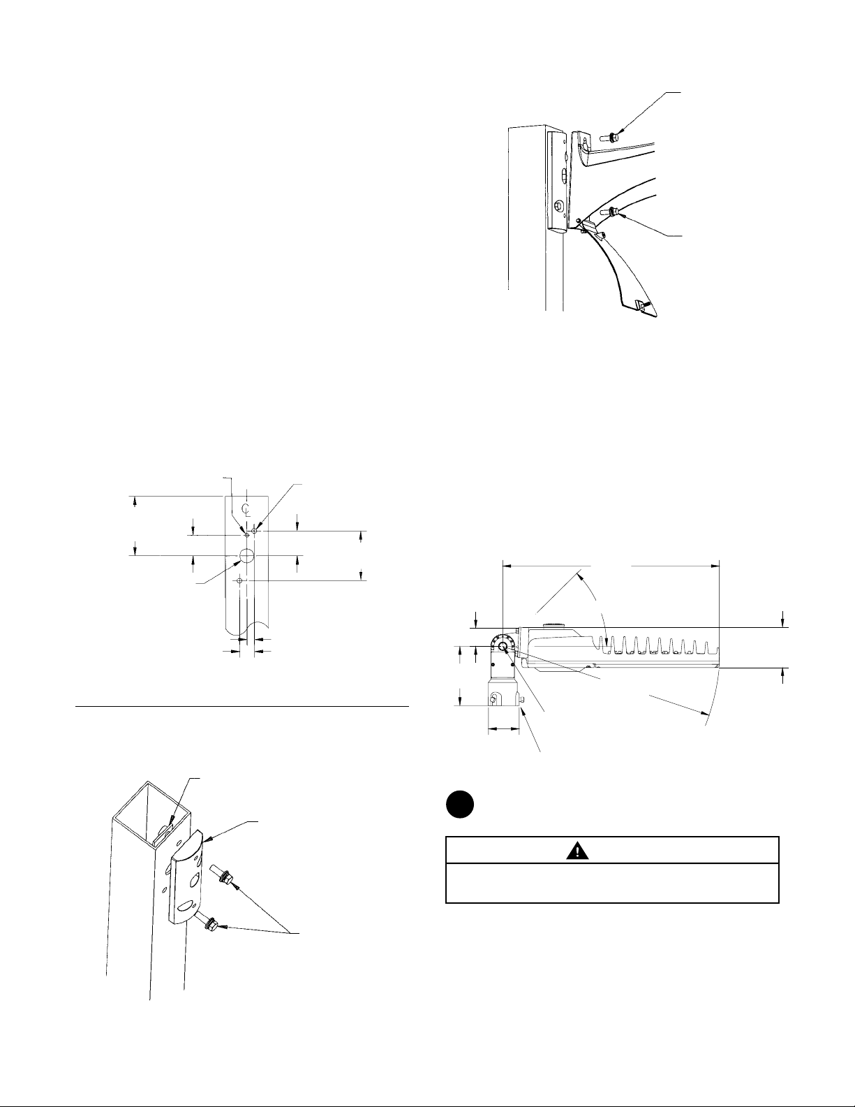
3c Square Pole Architectural Arm Mounting
This luminaire has been configured the same as 3b
and an adapter plate has been included to mount to
a square pole. Hole pattern on square pole shall be in
accordance with Figure 5.
• Orient adapter block so that oval shaped through
hole is closer to top than bottom of adapter.
• With adapter block end oriented properly, mount
adapter block to pole with the nut plate and 3/8-16
bolts and washer supplied as shown. Torque 3/8-16
bolts to 25 - 32ft-lbs (34-43 N-m). (See Figure 6)
• Place fixture against adapter block.
• Install 3/8 bolt, lock washer and washer in top as
shown and tighten into adapter block.
(See Figure 7)
• Open arm door and Install 3/8 bolt into tapped hole
of adapter block. (See Figure 7)
• Torque top and bottom bolts to 25 - 32 ft-lbs (34-43 N-m).
• Inspect installation to ensure fixture is secure.
DRILLING TEMPLATE
SQUARE POLE MOUNTING
5.2500 in.
(133 mm)
(MIN.)
1.250 in. DIA.
(32 mm DIA.)
.312 in. DIA.
(8 mm DIA.)
(HOLE)
1.8120 in.
(46 mm)
.438 in. DIA.
(11 mm DIA.)
(2 PLACES)
2.1960 in.
(56 mm)
4.3920 in.
(112 mm)
FIXTURE ARM TO ARM ADAPTER
FIGURE 7
Torque Top Bolt
to 25 - 32 ft-lbs.
(34-43 N-m)
Torque Bottom Bolt
to 25 - 32 ft-lbs.
(34-43 N-m)
3d Knuckle Slipfitter for 2-3/8 in. (60mm) to 3.0 in.
(76mm) OD Tenon
This luminaire has been configured specifically to provide
0 to 45° vertical aiming in 5° increments and mount on
2-3/8-inch O.D. (73mm) through 3-inch O.D. (76mm) pipe.
• Place slipfitter on the tenon.
• Three set screws are used to clamp the floodlight
securely to the pipe. Tighten set screws to 18-22 foot
pounds (24-30 N-m).
• To aim the luminaire, loosen the knuckle bolt, adjust
the aim 0 to 45° , and tighten to 45-50 ft-lbs (61-68 N-m).
• Inspect installation to ensure fixture is secure.
26.776 in.
[680 mm]
2.3 in.
[57 mm]
45° max upward aim
FIGURE 5
FIGURE 6
ADAPTER PLATE FOR
SQUARE POLE
Nut Plate
Adapter Block
.656 in. (17 mm)
1.312 in. (33 mm)
3/8-16 Washer and Bolts
Torque Bolts to 25 - 32ft-lbs.
(34-43 N-m)
7.3 in.
[186 mm]
4
3.805 in.
[97 mm]
WIRING
Tighten Knuckle Bolt
to 45-50 Foot Pounds
2-3/8 in. (60mm) to 3.0 in. (76mm) OD only
Tighten 3 Set Screws to 18-22
Foot Pounds
R26.9 in.
[R683 mm]
CAUTION
Risk of Damage or Injury: Door should be closed with
screw until fixture in final location.
• NOTE: Make all electrical connections in accordance
with the National Electrical Code and any applicable
local code requirements.
• Strain relief for incoming power must be provided in
the pole top by the customer.
• Supply Wire Type and Size, for Customer Connection
to Terminal Board: 16 AWG (1.5mm
(10mm2) Solid or Stranded.
2
) to 6 AWG
5.0 in.
[127 mm]
Page 4
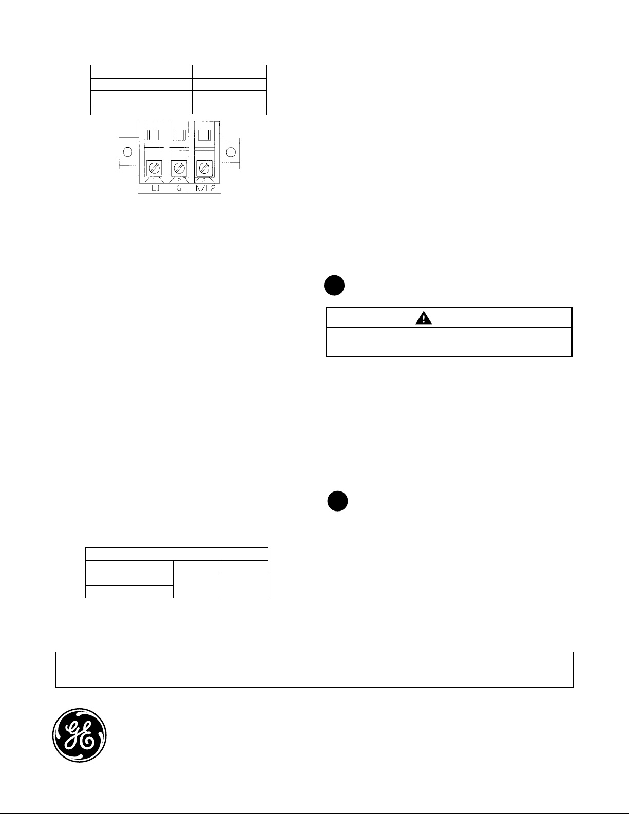
Terminal Board Connections:
Terminal Board Position Supply Type
L1 High Line
G Ground
N/L2 Low Line/Neutral
PE
Dimming Control (If Applicable):
• No external connections for Dimming are required
when the GE Dimming PE Control and GE Dimming PE
Receptacle is used.
• All dimming control connections will be made
between the Dimming PE and Luminaire through the
included PE Receptacle.
• Refer to instructions included with GE Dimming PE
Control regarding appropriate settings for dimming
control.
• NOTE: Verify that supply voltage is correct by
comparing it to nameplate inside door or on carton.
Photoelectric Control:
• (If option present)—Photoelectric control receptacle
should be oriented before control is installed.
• Loosen the two holding screws and rotate receptacle
until “North” is directed as near as possible to true
North.
• Verify that the grommet under the PE receptacle is
seated and that there are no gaps that will allow
water to enter the fixture from under the PE
receptacle.
• Tighten holding screws and install control.
Electrical Connection:
• Connect Luminaire wire leads to supply wire.
• Connections are to be made in interior of pole.
• Replace pole cap. A wiring diagram is provided on a
label inside luminaire for reference.
• For units without leads, connections may be
made to terminal board inside fixture.
• Note that care should be exercised not to pinch leads
between door and housing when closing the door.
External Dimming Control (If Applicable):
• Gray Lead = 0VDC (-)
• Violet Lead = Up To 10VDC (+)
Dimming Input/Output
Control Voltage1 Low (0-1.25V) High (7.5 -10V)
Nominal Input Wattage2
Nominal Lumen Output
• 1 Linear Transition between Low and High
• 2 Component and system tolerance may affect the
end point levels and linearity of transition
10% of Max 100%
2
Occupancy Sensor
(optional):
• The programmable occupancy sensor is shipped with
a default program which may be modified using the
button on the sensor.
• The sensor has a separate set of instructions on
programming which is included.
MAINTENANCE / CLEANING
5
WARNING
Risk of electric shock. Make certain power is off before
attempting any maintenance.
• To maintain high efficiency of the lens, occasional
cleaning of the outer lens surface may be needed,
with frequency dependent on local conditions.
• Use a mild soap or detergent, which is essentially
neutral pH (pH approximately 6 to 8), nonabrasive,
and which contains no chlorinated or aromatic
hydrocarbons.
• Wash thoroughly, using a soft cloth.
• Rinse with clean, cold water and wipe dry.
STORAGE
6
• Prior to installation, units should NOT be stored
outside in corrugated boxes (cardboard boxes) alone.
• Until installation, all units should be placed in a
covered dry storage area. The storage area should
not exceed -40°C (-40°F) to 50°C (122°F).
- This can be preferably in a roofed area or with a
tarp that is secured in such a way to keep water
off of the corrugated boxes (cardboard boxes).
These instructions do not purport to cover all details or variations in equipment nor to provide for every possible contingency to be met in
connection with installation, operation or maintenance. Should further information be desired or should particular problems arise which are not
covered sufficiently for the purchaser’s purposes, the matter should be referred to GE Lighting.
GE Lighting • 1-888-MY-GE-LED (1 - 888 - 69 - 43 - 533) • www.gelighting.com
GE Lighting is a subsidiary of the General Electric Company. Evolve and the GE brand and logo are trademarks of the General Electric Company.
© 2014 GE Lighting. Information provided is subject to change without notice. All values are design or typical values when measured under laboratory conditions.
35-201578-208 (Rev 09/09/14)
English
Page 5

GE
Guide d’installation
Lighting
Luminaire de zone à DEL Evolve
Appareil d’éclairage évolutif (EAS)
GEH-6016B
™
ARRÊT
AVANT DE COMMENCER
Lisez attentivement toutes ces instructions.
Conservez ces instructions pour référence future.
AVERTISSEMENT
Risque de choc électrique. Déconnectez l’alimentation
électrique avant d’installer ou réparer ce produit.
AVERTISSEMENT
Danger de blessure et de dommage matériel. L’appareil
tombera au sol s’il est mal installé. Suivez les instructions
d’installation.
ATTENTION
Danger de blessure. Lors de l’installation et de la réparation
de cet appareil, porter des lunettes et des gants de sécurité.
Cet appareil est conforme aux exigences de la partie 15 des règles
de la FCC. Son utilisation est sujette aux conditions suivantes : (1) cet
appareil ne doit pas causer d’interférences nuisibles; (2) cet appareil
doit accepter toutes les interférences reçues, y compris celles pouvant
causer un fonctionnement indésirable. Ce DEFR de la classe [ A ] est
conforme à la NMB-003 du Canada.
Remarque : Cet appareil a été testé et reconnu conforme aux
limites établies pour les appareils numériques de classe A, selon
la partie 15 des règles de la FCC. Ces limites sont conçues pour
assurer une protection raisonnable contre les interférences nuisibles
dans un environnement commercial. Cet appareil génère, utilise
et émet de l’énergie sous forme de radiofréquences, de sorte que
si son installation et son utilisation ne sont pas conformes à la
notice d’utilisation, il peut être la cause de parasites nuisibles aux
communications radio. L’utilisation de cet équipement dans une zone
résidentielle risque fort de causer des interférences nuisibles, auquel
cas l’utilisateur devra corriger le problème à ses propres frais.
imagination at work
• Ce luminaire a été conçu pour une utilisation à
l’extérieur et ne doit pas être employé sur un site mal
ventilé ni dans un endroit clos dont la température
ambiante peut être élevée.
• Pour obtenir des performances optimales, il doit
être installé et entretenu conformément aux
recommandations suivantes.
• Ce luminaire a été conçu pour fonctionner à des
températures ambiantes allant de -40°C à 50°C (-40°C
à 35°C pour >400W) et doit être installé horizontalement
à un poteau vertical de manière à ce que les diodes
soient orientées vers le bas, ou incliné vers le haut à
45° avec un adaptateur d’emboîtement.
SPÉCIFICATIONS
• Poids : Poids maximum < 50 lb (22,68 kg)
• EPA : Montage horizontal : 0,97 pi² max (0,09 m²)
Montage à 45° : 1,97 pi² max (0,18 m²)
• Classification IP : Module optique 65, boîtier électrique
standard : Homologation UL 1598 pour
environnement mouillé
Page 6

DÉBALLAGE
1
• Ce luminaire a été soigneusement emballé pour
qu’aucune pièce ne subisse de dommages durant
le transport.
• Procédez à une inspection pour vous en assurer.
MANUTENTION
2
• Si le luminaire est incorrectement manipulé hors de
son emballage, il risque d’être endommagé.
• Lorsque le luminaire est sorti de son emballage, il ne
doit pas recevoir le moindre coup ni être empilé.
ASSEMBLAGE
3
3b Montage avec bras architectural sur poteau rond
Ce luminaire a été spécialement configuré pour être monté sur
un poteau ayant un diamètre de 3,5 po à 4,5 po (89-114 mm). La
configuration des trous sur le poteau rond doit être conforme à la
Figure 2.
• Placez le luminaire contre le poteau.
• Installez le boulon de 3/8 po, la rondelle de frein et la
rondelle plate dans le haut (conformément à l’illustration) et
serrez dans la plaque d’écrou.
• Ouvrez le volet du bras et installez le boulon de 3/8 po, la
rondelle de frein et la rondelle plate dans le bras
(conformément à l’illustration) et serrez dans la plaque
d’écrou (voir les figures 3 et 4).
• Serrez les boulons du haut et du bas au couple de
25-32 lb-pi (34-43 Nm).
• Vérifiez la solidité de l’installation.
AVERTISSEMENT
Danger de blessure et de dommage matériel. L’appareil
tombera au sol s’il est mal installé. Suivez les instructions
d’installation.
Sélectionnez les instructions d’installation correspondant à
la méthode de montage applicable :
a. Montage sur joint coulissant
b. Montage avec bras architectural sur poteau rond
c. Montage avec bras architectural sur poteau carré
d. Adaptateur d’emboîtement pour tenon OD 2-3/8 po.
(60 mm) (angle d’inclinaison verticale de 0 à 45°)
3a Montage sur joint coulissant
Ce luminaire a été spécialement configuré pour être monté
sur des supports de tuyaux de 2 pouces (D. E. 2 3/8 po).
• Tenez le luminaire approximativement au niveau par
rapport au tuyau. Faites passer les fils dans le bras
et placez le joint coulissant sur le tuyau de 2 pouces
(51 mm) (D. E. 2 3/8 po / 60 mm).
• Serrez les quatre boulons de 3/8 po sur le joint
coulissant au couple de 10-14 lb-pi (14-19 Nm).
Après le serrage des boulons, serrez les contre-écrous
(voir la figure 1).
• Vérifiez la solidité de l’installation.
AVERTISSEMENT
Les boulons du joint coulissant ne doivent jamais être serrés
avec un couple dépassant 14 lb pi (19 Nm).
Boulons 3/8 de joint coulissant avec
contre-écrous
AVERTISSEMENT
Les boulons de montage du bras architectural ne doivent
jamais être serrés avec un couple dépassant 32 lb pi (43 Nm).
GABARIT DE PERFORATION
MONTAGE SUR POTEAU ROND
Bras de montage sur poteau rond avec
D.E. de 3,5 à 4,5 po (89 à 114 mm)
.312 po DIA.
5.2500 po
(133 mm)
(MIN.)
.750 po DIA.
(19 mm DIA.)
(TROU)
FIGURE 2
Serrer le boulon
supérieur au couple
de 25-32 lb-pi
(34-43N-m)
Serrer le boulon
supérieur au couple
de 25-32 lb-pi
(34-43N-m)
FIGURE 3
Plaque d’écrou
(8 mm DIA.)
1.8120 po
(46 mm)
Vue en coupe : Montage sur poteau rond
Bras architectural avec volet
Poteau
.438 po DIA.
(11 mm DIA.)
(2 ENDROITS)
2.7190 po
(69 mm)
Volet
Vis de volet de bras
Boulon, rondelle de
frein, rondelle plate
5.4380 po
(138 mm)
FIGURE 1
Vis de volet de bras
FIGURE 4
Page 7

3c Montage avec bras architectural sur
poteau carré
Ce luminaire a été configuré comme celui du paragraphe 3b
et une plaque adaptatrice a été ajoutée pour permettre une
installation sur un poteau carré. La configuration des trous sur
le poteau carré doit être conforme à la Figure 5.
• Orientez la plaque adaptatrice afin que le trou ovale soit
plus près du haut que du bas de la plaque.
• Après avoir vérifié l’orientation de l’extrémité de la plaque
adaptatrice, installez la plaque sur le poteau avec l’aide de
la plaque d’écrou, des boulons 3/8-16 et des rondelles
incluses, conformément à l’illustration. Serrez les boulons
3/8-16 au couple de 25-32 lb-pi (34-43 Nm)
(voir la figure 6).
• Placez le luminaire contre la plaque adaptatrice.
• Installez le boulon de 3/8 po, la rondelle de frein et la
rondelle plate dans le haut (conformément à la figure 7) et
serrez dans la plaque d’écrou.
• Ouvrez le volet du bras et installez un boulon de 3/8 po
dans le trou fileté du bloc adaptateur (voir la figure 7).
• Serrez les boulons du haut et du bas au couple de
25-32 lb-pi (34-43 Nm).
• Vérifiez la solidité de l’installation.
GABARIT DE PERFORATION
MONTAGE SUR POTEAU CARRÉ
FIGURE 5
5.2500 po
(133 mm)
(MIN.)
1.250 po DIA.
(32 mm DIA.)
.312 po DIA.
(8 mm DIA.)
1.8120 po
(46 mm)
(TROU)
PLAQUE ADAPTATRICE POUR
POTEAU CARRÉ
Plaque d’écrou
.438 po DIA.
(11 mm DIA.)
(2 ENDROITS)
2.1960 po
(56 mm)
.656 po (17 mm)
1.312 po (33 mm)
4.3920 po
(112 mm)
BRAS DU LUMINAIRE SUR ADAPTATEUR
FIGURE 7
Serrer le boulon
supérieur au couple de
25-32 lb-pi (34-43 Nm)
Serrer le boulon
inférieur au couple de
25-32 lb-pi (34-43 Nm)
3d Adaptateur d’emboîtement pour OD tenon de
2-3/8 po. (60 mm) à 3 po. (76 mm)
Ce luminaire a été spécifiquement configuré pour fournir une
inclinaison verticale de 0 à 45° par incréments de 5° et se
sur un tuyau OD de 2-3/8-po. (73 mm) à 3 po. (76 mm).
• Placez l’adaptateur d’emboîtement sur le tenon.
• On utilise trois vis de fixation pour solidement fixer le projecteur
au tuyau. Serrez les vis de fixation jusqu’à 18-22 pied-livre
(24-30 N-m).
• Pour orienter le luminaire, desserrez l’écrou articulé, ajustez
l’orientation entre 0 et 45° et vissez jusqu’à 45-50 pied-livre
(61-68 N-m).
• Vérifiez la solidité de l’installation.
26.776 in.
26.776 in.
[680 mm]
(680 mm)
2.3 in.
2.3 in.
(57 mm)
[57 mm]
7.3 in.
7.3 in.
(186 mm)
[186 mm]
3.805 in.
3.805 in.
[97 mm]
(97 mm)
45° max upward aim
Orientation vers le haut 45° max.
R26.9 in.
R26.9 in.
[R683 mm]
(R683 mm)
Serrez écrou articulé
Tighten Knuckle Bolt
to 45-50 Foot Pounds
jusqu’à 45-50 pied-livre
2-3/8 in. (60mm) to 3.0 in. (76mm) OD only
OD de 2-3/8 (60 mm) à 3 po. (76 mm) uniquement
Tighten 3 Set Screws to 18-22
Serrez 3 vis de fixation jusqu’à 18-22 pied-livre
Foot Pounds
monter
5.0 in.
5.0 in.
[127 mm]
(127 mm)
FIGURE 6
Plaque adaptatrice
Boulons 3/8-16 et rondelles
Serrer les boulons au couple
de 25-32 lb-pi (34-43 Nm)
CÂBLAGE
4
ATTENTION
Danger de blessure et de dommage matériel. Le volet
doit être fermé avec sa vis jusqu’à ce que le luminaire soit
à son emplacement final.
• REMARQUE: Toutes les connexions doivent être
conformes aux normes électriques nationales et à la
réglementation locale en vigueur (code électrique du
Canada et réglementation locale applicable).
• Un dispositif anti-tension doit être installé par le client
sur le câble d’alimentation en haut du poteau.
• Type et taille du câble d’alimentation (pour
connexion par le client sur plaque de connexions) :
16 AWG (1,5mm2) à 6 AWG (10mm2) plein ou tressé.
Page 8

Connexions de la plaque de connexions :
Position sur la plaque de connexions Type d’alimentation
L1 Ligne de phase
G Terre
N/L2 Ligne basse/neutre
Gradateur photoélectrique (si applicable)
• Aucune connexion externe de gradation n’est
nécessaire lorsque la commande de gradateur PE et
le réceptacle de gradateur PE de GE sont utilisés.
• Toutes les connexions de commande de gradation
seront réalisées entre le gradateur PE et le luminaire
via le réceptacle PE inclus.
• Lire les instructions incluses avec la commande de
gradateur PE de GE concernant les réglages
appropriés de la commande de gradateur.
• REMARQUE: Assurez vous que la tension électrique
est adéquate en vérifiant la plaque signalétique à
l’intérieur du volet ou sur la boîte.
Commande photoélectrique :
• (Si l’option est choisie) Le réceptacle de la commande
peut être orienté avant d’installer la commande.
• Desserrez les deux vis de retenue et faites tourner
le réceptacle jusqu’à ce que l’inscription « North » soit
orientée le plus près possible du nord véritable.
• Assurez-vous que la douille sous le réceptacle de
commande photoélectrique est bien appuyée et qu’il
n’existe aucun espace d’infiltration d’eau sous le réceptacle.
• Serrez les vis de retenue et installez la commande.
Branchements électriques :
• Connectez les fils conducteurs du luminaire au câble
d’alimentation.
•
Les connexions doivent être faites à l’intérieur du poteau.
• Réinstallez le capuchon du poteau. Un schéma de
câblage figure sur une étiquette à l’intérieur du
luminaire pour référence.
• Si vous utilisez un joint sans fils conducteurs, les
connexions peuvent être faites sur la plaque de
connexions à l’intérieur du luminaire.
• Faites attention de ne pas pincer les fils entre le volet
et le boîtier lorsque vous fermez le volet.
Détecteur de présence (en option) :
• Le détecteur de présence programmable est expédié
avec une programmation par défaut que l’on peut
modifier à l’aide du bouton situé sur le détecteur.
• Le détecteur est fourni avec des instructions de
programmation séparées.
ENTRETIEN ET NETTOYAGE
5
AVERTISSEMENT
Risque de choc électrique. Avant de commencer toute
opération d’entretien, assurez-vous que l’alimentation
électrique est coupée.
• Pour conserver l’efficacité de la lentille, nettoyez
périodiquement la surface extérieure de la lentille
fréquence des nettoyages dépendra des conditions locales).
• Utilisez un savon doux ou un détergent essentiellement
neutre (ayant un pH d’environ 6 à 8), sans abrasif et sans
hydrocarbure chloré ou aromatique.
• Lavez à fond avec la solution de nettoyage en
utilisant un chiffon doux.
• Rincez avec de l’eau froide et propre, puis essuyez.
ENTREPOSAGE
6
(la
•
Gradateur externe (si applicable) :
• Fil gris = 0 V c.c. (-)
• Fil violet = Jusqu’à 10 V c.c. (+)
Gradation, entrée/sortie
Tension de commande1 Basse (0-1.25V) Élevée (7.5-10V)
Puissance nominale d’entrée2
Sortie nominale en lumens
• 1 Transition linéaire entre basse et élevée
10% du Maxi 100%
2
Avant leur installation, les luminaires ne doivent PAS être
entreposés à l’extérieur dans de simples boîtes en carton.
• Jusqu’à leur installation, tous les luminaires doivent
être conservés dans un lieu de stockage couvert et
sec. La température du site de stockage doit se situer
entre -40 ºC et 50 ºC (-40 ºF et 122 ºF).
- Conservez-les préférablement sous un toit ou sous
une bâche installée solidement de façon à ce que
l’eau ne puisse atteindre les boîtes en carton.
• 2 Les tolérances des composants et du système peuvent affecter
les niveaux de point final et la linéarité de la transition
Ces instructions n’ont pas pour but de couvrir tous les détails et toutes les variantes de l’équipement, ni de répondre à tous les impondérables
possibles en relation avec l’installation, le fonctionnement et l’entretien. Si vous désirez plus d’informations ou si des problèmes particuliers
surviennent qui ne sont pas couverts suffisamment pour les besoins de l’acheteur, le sujet doit être soumis à GE Lighting.
GE Lighting • 1-888-MY-GE-LED (1 - 888 - 69 - 43 - 533) • www.gelighting.com
GE Lighting est une filiale de la General Electric Company. Evolve ainsi que la marque et le logo GE sont des marques commerciales déposées de la General Electric Company.
© 2014 GE Lighting. Les informations fournies ici sont susceptibles de changer sans préavis. Toutes les données sont des valeurs de conception ou caractéristiques lors de leur
mesure en conditions de laboratoire.
35-201578-208 (Rev 09/09/14)
French
Page 9

GE
Lighting
Lámpara de Área Evolve
Lámpara Escalable (EAS, por sus siglas en inglés)
ANTES DE EMPEZAR
Lea estas instrucciones por completo y
detenidamente. Guarde estas instrucciones para
uso futuro.
ADVERTENCIA
Guía de Instalación
GEH-6016B
™
LED
Riesgo de descarga eléctrica. Desconecte la fuente
de energía antes de dar mantenimiento o al instalar el
producto.
ADVERTENCIA
Riesgo de lesiones o daño. La unidad caerá si no es instalada
apropiadamente. Siga las instrucciones de instalación.
ADVERTENCIA
Riesgo de lesiones. Use gafas de protección y guantes
durante instalación y servicio.
Este aparato cumple con Parte 15 de las Reglas FCC. Su operación
está sujeta a las siguientes dos condiciones: (1) Este aparato no puede
causar interferencia perjudicial, y (2) este aparato debe aceptar
cualquier interferencia recibida, incluyendo interferencia que pueda
causar una operación no deseada. Esta Clase [A] RFLD cumple con
el estándar Canadiense ICES-003. Ce DEFR de la classe [ A ] est
conforme à la NMB-003 du Canada.
Nota: Este equipo ha sido probado y cumple con los límites para la
Clase A de aparatos digitales, conforme a la parte 15 de las Reglas
FCC. Estos límites están diseñados para proveer protección necesaria
para contrarrestar interferencia perjudicial cuando el equipo está en
operación en un ambiente comercial. Este equipo genera, usa y puede
irradiar energía de radio frecuencia y, si no es instalado y usado
conforme a las instrucciones del manual, puede causar interferencia
perjudicial a radiocomunicaciones. La operación de este equipo en
una zona residencial probablemente causará interferencia perjudicial,
en cual caso el usuario deberá corregir por su propia cuenta.
imagination at work
• La luminaria está diseñada para iluminación exterior,
y no deberá ser usada en áreas con ventilación
limitada, o a altas temperaturas ambientales.
• Para mejores resultados instale y mantenga de
acuerdo con las siguientes recomendaciones.
• Las luminarias están diseñadas para operar en tem-
peraturas ambiente de -40°C a 50°C (-40°C a 35°C para
>400W) y para ser montada en posición horizontal a
un poste vertical con los LEDs apuntando hacia abajo,
o inclinados al alza hasta a 45° con la ayuda de un
vástago desmontable articulado.
ESPECIFICACIONES
• Peso: Peso máximo <50 libras (22.68 kg)
•
Área Proyectada Efectiva (EPA, por sus siglas en inglés):
Montaje horizontal: 0.97 pies2 max (0.09 m2)
Montaje a 45°: 1.97 pies2 max (0.18 m2)
• Grado IP: IP65 óptico, caja de protección eléctrica
estándar:
UL 1598 Especificado para entorno húmedo
Page 10

DESEMPAQUE
1
• Esta luminaria ha sido empacada adecuadamente
para que ninguna parte se dañe durante su envío.
• Inspeccione para confirmar su estado.
MANEJO
2
• Daños pueden ocurrir si la luminaria se maneja
inadecuadamente fuera de su empaque.
• No golpee o almacene la luminaria después de haberla
removido de su empaque.
MONTAJE
3
3b Montaje con Brazo para Poste Redondo
Esta luminaria ha sido configurada específicamente para ser
montada a un poste redondo de 3.5 a 4.5 pulgadas (89-114
mm) de diámetro. La plantilla de perforación deberá ser igual
a la Figura 2.
• Coloque la luminaria contra el poste.
• Instale las tuercas de 3/8, la arandela de seguridad
y arandela en la parte superior como se muestra y
apriete a la placa para tuerca.
• Abra la puerta del brazo e instale el tornillo de 3/8, la
arandela de seguridad y arandela dentro del brazo
como se muestra y apriete a la placa para tuerca.
(Figura 3 y 4).
• Aplique torque de 25 a 32 libras por pie (42-43 N-m) a
los tornillos superiores e inferiores.
• Inspeccione la instalación para asegurarse que el
equipo esté firmemente sujeto.
ADVERTENCIA
Riesgo de lesión o daño. La unidad caerá si no es instalada
apropiadamente. Siga las instrucciones de instalación.
Siga las instrucciones de instalación apropiadas de acuerdo
al método de montaje elegido:
a. Montaje de Vástago Desmontable
b. Montaje con Brazo Arquitectónico para Poste Redondo
c. Montaje con Brazo Arquitectónico para Poste Cuadrado
d. Vástago desmontable articulado para acoplamiento
de 2- 3/8 pulg. (60mm) de diámetro exterior (0 a 45°
inclinación vertical)
3a Montaje de Vástago Desmontable
Esta luminaria ha sido configurada específicamente para
ser montada a un tubo de soporte de 2 pulgadas (2-3/8
pulgadas de diámetro total).
• Mantenga la luminaria aproximadamente a nivel del
tubo de soporte. Jale los cables a través del brazo y
coloque el vástago desmontable sobre el tubo (2-3/8
pulgadas 60 mm de diámetro total) de 2 pulgadas (51mm)
•
Apriete los (4) tornillos 3/8 del vástago desmontable a
10-14 libras por pie (14-19 N-m). Apriete las tuercas después
que los tornillos hayan sido apretados. (Vea Figura 1).
• Inspeccione la instalación para asegurarse que el
equipo esté firmemente sujeto.
ADVERTENCIA
Bajo ninguna circunstancia se deberá apretar los tornillos
con un nivel de torque mayor a 14 libras por pie (19 N-m).
Bajo ninguna circunstancia se deberá apretar los tornillos del
brazo con un torque mayor a 32 libras por pie (43 N-m).
5.2500 pulg.
(133 mm)
(MIN.)
.750 in. DIA.
(19 mm DIA.)
FIGURA 2
Aplique 25-32 libras por
pie de torque a tornillo
Aplique 25-32 libras por
pie de torque a tornillo
(34-43N-m)
(34-43N-m)
FIGURE 3
A
ADVERTENCIA
PLANTILLA DE PERFORACIÓN
Brazo de montaje para poste redondo de diámetro
(ORIFICIO)
superior
inferior
MONTAJE EN POSTE REDONDO
exterior de 3.5 a 4.5 pulgadas (89 a 114mm)
.312 pulg. DIA.
(8 mm DIA.)
1.8120 pulg.
(46 mm)
.438 pulg. DIA.
(11 mm DIA.)
(2 LUGARES)
2.7190 pulg.
(69 mm)
Puerta
Tornillo para Puerta del Brazo
5.4380 pulg.
(138 mm)
FIGURA 1
Tornillos 3/8 y Tuercas del Vástago Desmontable
Placa para Tuerca
FIGURA 4
Vista Seccional: Brazo para Montaje en Poste Redondo
Brazo Arquitectónico con Puerta
Poste
Tuerca de Poste, Arandela
de Seguridad, Arandela
Tornillo para Puerta del Brazo
Page 11

3c Montaje con Brazo para Poste Cuadrado
Esta luminaria está configurada igual que 3b y una
placa adaptadora ha sido incluida para ser montada a
un poste cuadrado. La plantilla de perforación deberá
ser igual a la Figura 5.
• Oriente el bloque adaptador de manera que el hoyo
ovalado esté más cercano a la parte superior que la
inferior del adaptador.
• Con el borde del bloque adaptador correctamente
orientado, monte el bloque adaptador al poste con
la placa para tuerca y los tornillos de 3/8-16 y la
arandela incluidos como se muestra. Aplique 25-32
libras por pie (34-43 N-m) de torque a los tornillos de
3/8-16. (Vea Figura 6)
• Coloque la lámpara contra el bloque adaptador
• Instale el tornillo de 3/8, la arandela de seguridad, y
la arandela en la parte superior como se muestra y
ajuste al bloque adaptador. (Vea Figura 7)
• Abra la puerta del brazo e instale el tornillo de 3/8 al
orificio roscado del bloque adaptador. (Vea Figura 7)
• Aplique 25-32 libras por pie (34-43 N-m) de torque a
los tornillos superiores e inferiores
• Inspeccione la instalación para asegurarse que el
equipo este firmemente sujeto.
PLANTILLA DE PERFORACIÓN
MONTAJE EN POSTE CUADRADO
FIGURA 5
5.2500 pulg.
(133 mm)
(MIN.)
1.250 pulg. DIA.
(32 mm DIA.)
(HOLE)
.312 pulg. DIA.
(8 mm DIA.)
1.8120 pulg.
(46 mm)
PLACA ADAPTADORA PARA
POSTE CUADRADO
Placa de Tuerca
.438 pulg. DIA.
(11 mm DIA.)
(2 LUGARES)
2.1960 pulg.
(56 mm)
.656 pulg. (17 mm)
1.312 pulg. (33 mm)
4.3920 pulg.
(112 mm)
BRAZO DE LÁMPARA PARA
ADAPTADOR DE BRAZO
FIGURA 7
Aplique 25-32 libras por pie
de torque a tornillo superior
(34-43N-m)
Aplique 25-32 libras por pie
de torque a tornillo inferior
(34-43N-m)
3d Vástago Desmontable Articulado para un
acoplamiento de diámetro exterior de 2-3/8
pulg. (60mm) a 3.0 pulg. (76mm).
Esta luminaria ha sido configurada específicamente para
ser posicionada de una manera vertical de 0° a 45° en
incrementos de 5° y montada en un tubo de 2-3/8-pulg. de
diámetro exterior. (73mm) a 3-pulg. de diámetro exterior. (76mm).
• Coloque el vástago desmontable en el acoplamiento.
• Los tres tornillos se usan para ajustar la lámpara
seguramente al tubo. Apriete los tornillos con un
torque de 18-22 libras pies (24-30 N-m).
• Para inclinar la luminaria, desatornille el perno de la
articulación, ajuste la inclinación de 0 a 45° , y apriete
a 45-50 libras pie (61-68 N-m).
• Inspeccione la instalación para corroborar que la
instalación es segura.
26.776 pulg.
26.776 in.
[680 mm]
(680 mm)
2.3 pulg.
2.3 in.
(57 mm)
[57 mm]
7.3 pulg.
7.3 in.
(186 mm)
[186 mm]
3.805 in.
3.805 pulg.
[97 mm]
(97 mm)
45° max upward aim
45° de inclinación al alza máxima
5.0 pulg.
5.0 in.
[127 mm]
(127 mm)
R26.9 in.
R26.9 pulg.
[R683 mm]
(R683 mm)
Apriete el tornillo a
Tighten Knuckle Bolt
to 45-50 Foot Pounds
45-50 libras pie
2-3/8 in. (60mm) to 3.0 in. (76mm) OD only
2-3/8 pulg. (60mm) a 3.0 pulg. (76mm) Diámetro Exterior
Tighten 3 Set Screws to 18-22
solamente. Apriete los 3 tornillos a 18-22 libras pie.
Foot Pounds
FIGURE 6
Bloque Adaptador
3/8-16 Arandela y Tornillo
Aplique 25-32 libras por pie
(34-43 N-m) de torque a
tornillos
CABLEADO
4
PRECAUCIÓN
Riesgo de lesiones o daño: Puerta debe de estar cerrada
con tornillo hasta que el aparato esté en su posición final.
• NOTA: Todas las conexiones eléctricas deberán
realizarse de acuerdo con el Código Eléctrico Nacional y
conforme a códigos locales correspondientes.
• Liberación de tensión debe de ser proporcionado por el
usuario para la fuente de poder en el poste.
• Proporcione el tipo y tamaño de cable para la conexión
del usuario a la placa terminal: 16 AWG (1.5mm2) a 6
AWG (10mm2) Sólido o Trenzado.
Page 12

Conexiones de Placa Terminal:
Posición de Placa Terminal Tipo de Suministro
L1 Línea Alta
G Puesta a Tierra
N/L2 Línea Baja/Neutro
• NOTA: Verifique que el voltaje de alimentación sea
correcto comparándolo con la placa del fabricante
localizada dentro de la puerta o en la caja.
Control Fotoeléctrico:
• (Si la opción está presente)—Receptáculo de control
fotoeléctrico debe de ser orientado antes de instalar el
control.
• Afloje los dos tornillos sujetadores y gire el receptáculo
hasta que el “norte” se dirija lo más posible al norte real.
• Verifique que el anillo debajo del receptáculo PE esté
fijo y que no hay ningún espacio que deje entrar agua
al aparato por debajo del receptáculo PE.
• Apriete los tornillos sujetadores e instale el control.
Conexión Eléctrica:
• Conecte los conectores de cable de la luminaria al
cable de suministro.
•
Conexiones deberán de ser hechas en el interior del poste.
•
Reemplace la tapa del poste. Diagrama de cableado está
como referencia en la etiqueta dentro de la luminaria
•
Para las unidades sin conectores, las conexiones puedes
ser hechas en la placa terminal dentro del aparato.
• Tenga cuidado de no pellizcar los conectores de cable
entre la puerta y la caja al cerrar la puerta.
Control Regulador de Intensidad PE (Si aplica):
•
Ninguna conexión externa para regular la intensidad
son requeridas cuando el Control Regulador de
Intensidad PE de GE y el Receptáculo del Regulador
de Intensidad PE de GE son usados.
• Todas las conexiones de regulación de intensidad
serán hechas entre el regulador de intensidad PE y la
luminaria a través del receptáculo PE incluido.
• Consulte las instrucciones incluidas en el Control
Regulador de Intensidad PE de GE en cuanto a la
configuración adecuada para el control regulador de
intensidad.
Sensor de Presencia (opcional):
•
El sensor de presencia programable se envía con un
programa estándar el cual puede ser modificado usando el botón en el sensor.
• El sensor tiene incluido un set de instrucciones de
programación por separado.
MANTENIMIENTO/LIMPIEZA
5
ADVERTENCIA
Riesgo de descarga eléctrica: Desconecte la fuente de
energía antes de dar mantenimiento.
• Para mantener la alta eficiencia del lente, limpieza
ocasional de la superficie exterior del lente puede
ser necesaria y su frecuencia dependerá de las
condiciones locales.
• Use un detergente o jabón suave, con un pH neutro,
no abrasivo y que no contenga hidrocarbonos
aromatizantes o con cloro.
• Lave a fondo, usando un paño suave.
• Enjuague con agua fría y limpia y seque.
Control Regulador de Intensidad Externo (Si aplica):
• Conector Gris = OVDC (-)
• Conector Violeta = Hasta 10VDC (+)
Entrada/Salida de Regulador de Intensidad
Control de Voltaje1 Bajo (0-1.25V) Alto (7.5-10V)
Entrada Nominal de Potencia
Salida Nominal de Lumen2
1
Transición linear entre alto y bajo
•
• 2 Tolerancia de componente y sistema puede afectar
los niveles finales y la linealidad de transición
Estas instrucciones no pretenden cubrir todos los detalles o variaciones de equipo, ni cada posible contingencia encontrada en conexión a la
instalación, operación o mantenimiento. Si más información es requerida ó ciertos problemas particulares surgen, los cuales no son abarcados
suficientemente para los requerimientos del comprador, el asunto debe de ser referido a GE Iluminación.
2
10% de Máximo
100%
ALMACENAMIENTO
6
• Antes de su instalación, las unidades no deben de
ser almacenadas a la intemperie solo en cajas (cajas
de cartón) corrugadas.
• Todas las unidades deben de ser almacenadas en
un área seca y cubierta hasta que sean instaladas.
El área de almacenamiento no deberá de exceder
-40°C (-40°F) a 50°C (122°F).
- Éste puede ser preferiblemente en un área
techada o con una lona que proteja a las cajas
corrugadas (cajas de cartón) contra el agua.
GE Lighting • 1-888-MY-GE-LED (1 - 888 - 69 - 43 - 533) • www.gelighting.com
GE Lighting es una subsidiaria de la Compañía General Electric. Evolve y la marca y logotipo de GE son marcas registradas de la Compañía General Electric.
©2014 GE Lighting. La información se encuentra sujeta a cambio sin previo aviso. Todos los valores son de diseño, o valores típicos al momento de ser medidos
bajo condiciones de laboratorio.
35-201578-208 (Rev 09/09/14)
Spanish
 Loading...