

Page 1
guidelines
GE Industrial Control Systems
Instruction Book
100353
Page 2

These instructions do notpurport to cover all details or variations in equipment, nor to provide everypossible contingency
to be met during installation, operation, and maintenance.
further information is desired or if particular problems
arise that are not covered sufficiently for the purchaser’s purpose, the matter should be referred to GE industrial
Control Systems.
This document contains proprietary information of General Electric Company, USA and is furnished to its customer
to assist that customer in the installation, testing, operation, and/or maintenance of the equipment described.
This document shall not be reproduced in whole or in part nor shall its contents be disclosed to any third party without
the written approval of GE industrial Control Systems.
1998 by General Electric Company, USA.
rights reserved.
Page 3
TABLE OF CONTENTS
1. EMC DIRECTIVE, INTERPRETATION CEMEP AND APPLICABLE STANDARDS . . . . . . . 5
2. IMMUNITY: ESD AND FAST TRANSIENT (BURST)
. . . . . . . . . . . . . . . . . . . . . . . . . . . . . . . . . . . . . . . . . . . . . . . . . .
3. EMISSIONS: RADIO-FREQUENCY CONDUCTED AND RADIATED
4.
FILTERS
4.1 ECF FILTERS
4.2
4.3 TABLES OF FILTERS SELECTION
FILTERS (FN,
5. EMC COMPLIANT ELECTRICAL CABINET WIRING RULES
..............................................................................................................
.................................................................................................................................
...........................................................................
............................................................................................
...........................................
PANELS
REMOVAL OF THE PAINT FROM THE SUPPORT AREAS
GROUND TERMINALS
GROUND TERMINALS OF THE CONVERTER
GROUND
SHIELDOFCABLES FOR ANALOG SIGNALS
GROUND CONNECTION OF THE ANALOG ZERO VOLT AND
GROUND CONNECTION OF THE ANALOG ZERO VOLT FOR OPTIONAL TBO CARD
SHIELDING OF THE SUPPLY FOR AN AC MOTOR
GROUND CONNECTION TO BOTH SIDES OF THE CABLE SHIELD (AC MOTOR)
PIGTAIL AVOIDING .............................................................................................................
SUPPLYCABLES OF THEDCMOTOR
DIRECT CONNECTION BETWEEN GROUND BUS AND MOTOR CHASSIS..
MAX LENGTH OF THE AC MOTOR’S CABLES INSIDE THE CABINET
ENCODER CABLES
MOUNTING SEQUENCE FOR FN, COMPACT AND RANGER FILTERS WITH CONVERTER AND
LINE REGEN CONVERTER
GROUNDING OF THE FN, COMPACT AND RANGER FILTERS WITH CONVERTER AND ‘LINE
REGEN CONVERTER
MOUNTING SEQUENCE FOR FN, COMPACT AND RANGER WITH INVERTER
GROUNDING OF THE FN, COMPACT AND RANGER FILTERS WITH INVERTER
MOUNTING SEQUENCE FOR ECF FILTERS
GROUNDING OF THE ECF FILTERS
MOUNTING SEQUENCE OF THE FILTERS:
Filtering connection using
Filtering connection using ECF filters..................................................................................
AND
CABINETS
TERMINAL
....................................................................................................
.....................................................
THE INVERTER
THE CHOKE..
.............................................................................................................
...................................................................................................
...........................................................................................................
FN, COMPACT or RANGER
..........................................................................
.......................................................................
................................................................................
......................................................................
V REFERENCE POTENTIAL13
...............................................................
.................................................................................
........................................................................
....................................................................................
SUMMARY TABLE ............................................
filters: ............................................
.............
..................
.........................
..................................
....................
..................
6
7
8
8
9
10
13
13
13
13
13
13
14
14
14
14
14
14
15
15
15
15
15
15
15
16
16
16
17
ATTACHMENT A
...............................................................................................................
B
. . . . . .
26
27
Page 4

LIST OF FIGURES
1
EMC DIRECTIVE, INTERPRETATION CEMEP AND APPLICABLE- STANDARDS
TABLES
5
2. IMMUNITY: ESD AND FAST TRANSIENT (BURST)
3. EMISSIONS: RADIO-FREQUENCY CONDUCTED AND RADIATED
FILTERS
Figure 4. I: ECF filters
Figure
4.2. I:
Figure
4.2.2: Filter
Figure
4.2.3:
Tab/e1:Selection of the filters
Table
Table
3:
Filters
Table 4: Filters
Table 5: Filters
..............................................................................................................
8
connection
Filter
connection on Converter..
Filter connection on Line Regen
for DV-300 converters
Filters
Filters for
for AV-300
for AV-300i
for RS-300
on
.................................................................................................................
converters
line regen
.........................................................................................................
....................................................................................................
Converter
..........................................................................................................
..........................................................................................................
...............................................................................................................
..............................................................................................................
converters..
..................................................................................
...........................................................................................
5. EMC COMPLIANT ELECTRICAL CABINET WIRING RULES
Figure 5.1:
Figure 5.2: Converter
Figure
5.3:
Figure
5.4:
Figure
5.5:
Figure 5.6: Functional connection diagram of a FN, COMPACT or RANGER filter with AV300 inverters
Figure 5.7: Functional connection
Figure
Figure 5.9: Functional connection diagram of a FN, COMPACT or RANGER filter with line regen converters
Figure 5. 70: Functional connection diagram
Figure 5.7 1: Functional connection diagram of a ECF
Figure
5.12:
Figure
5.13:
Regen Converter
Line
Converter
OMEGA plug: grounding at
Functional connection diagram of a FN, COMPACT or RANGER filter with converters
side
side
Double
cabinet’s layout..
....................................................................................................................
.......................................................................................................................
shielded cable. .....................................................................
a
diagram of a S-...
of a ECF filter with inverters..
layout.........................................................................................................
......................................................................................................
filter with
filter with converters..
..................................................
............................
.................................... 13
.............................................
................... 20
...................................................... 22
..................................................
.
......
..........
6
9
9
9
12
12
72
16
76
17
17
18
19
23
24
25
A
ATTACHMENT B
. . .
. . . . . . . . . . . .
26
27
Page 5

EMC GUIDELINES
1. EMC DIRECTIVE, INTERPRETATION CEMEP AND APPLICABLE
STANDARDS’
The EMC directive
marketable in the CEE must be electromagnetically compatible with the external world.
This means the equipment fairly immune to admissible environmental noise-levels and low emitting according
to the allowed
Sales channels: Restricted Distribution
Unrestricted Distribution (see Glossary)
Installation environment
Inherent function of the device: direct or indirect
Assembly: Professional Assembler
Obviously, the directive does not point out in detail neither the criterions which have to be applied in order to
judge a device EM-compatible, nor the actions that have to be taken, in order to keep it in that way. That task is
up to the Product Standard concerned with the product; if this would not exist or if the part concerning EMC had
been missed, the product manufacturer must refer to the Generic Standard.
Therefore, being EMC conformant, does not mean high-immunity and low-emissions, but it implies the
adherence to the limits imposed by a product standard, which cannot foresee any limitation.
Seeing the wide range of products to which the directive refers and its legal nature, it became necessary for the
manufacturers of products of the same typology, to give an interpretation of the directive, with no official value,
but whose validity is linked with the acknowledgment of the association of some categories. (The only document
recognized by CE is the directive).
updated from the
limitations are related to the characteristics of the equipment itself.
points out that each electrical and electronical equipment
In case of Power Device Systems (PDS, including in this category both single-drives and systems, which are the
assembling of single device, composing a machine) there exists an interpretation, well-known as Document
CEMEP, recognized by the most important European association of categories: ANIE, GAMBICA, GIMELEC,
ZVEI, Manufacturers
The document classifies the PDS in four validity fields (CEMEP Validity Fields, see attachment B) according to
the above mentioned characteristics and it
the following points:
Declaration of conformity
Responsibility of the constructor and installer
The EMC directive is applied to the GE product following the interpretation CEMEP.
In accordance with the interpretation CEMEP GE products, considered that:
sales channel correspond to the definition of Restricted Distribution
the products haven’t any direct function (intrinsic)
Denmark.
to each of the four classes duties and prohibitions concerning
Page 6
the assembley must be a professional one will be considered “Complex Component” (CEMEP Validity
Field no 2) therefore
It is not possible to apply the CE Mark concerning EMC Standard
It is not possible to draw up the Declaration of Conformity regarding EMC Standard
The responsibility of the EMC Standard is of the installer and not of the manufacturer (GE)
The producer (GE) is responsible for giving the installer all the necessary indications to keep the final
product EMC conform.
CE marking and declaration of conformity, as known , are linked with the standard, who are referred. GE’s
products show the mark and, as prescribed, in the handbooks it has been specified how this mark is conformed
to the Low Voltage Directive, for which it has been also drawn up a declaration of conformity (see attachment
A). Whenever the EMC Standard is concerned, the
guidelines.
filters must be utilized and used according to installation
The product standard for the PDS, EN61800 (drawn up in
and describes completely the prescriptions in terms of immunity and emissions for PDS.
In this standard it has been assigned the noise-levels to which the equipment must be submitted under the
immunity test and the allowed emission limits.
On the whole the machine manufacturer, or GE customers, belong to the validity field CEMEP number 4 as
“System /apparatus” and therefore they have the obligation of CE Mark and Declaration of Conformity.
The machine manufacturer has the responsability of EMC conformity. They have the right to receive all the
necessary indications (filter, installation, etc.) in order to comply with EMC standard from the single component
producers.
Almost all the products do not have product standard as far as EMC concerns and they have to refer to the
generic standards, which are EN50081-1 and 50081-2 as far as emissions in residential and industrial environments
and
These documents, as far as the radio-frequency emissions concern, refer to the specific standard EN55011
which define the emissions limits in industrial environment (class A limits) and residential (class B limits).
This is why, despite the less restrictive limitation imposed by the product standard
refer to the limits EN5501 1-A and B, as far as the radio-frequency emissions are concerned.
In the next two sections immunity and emission tests and limitation prescribed in
and
regarding the immunity in the above mentioned environments.
in the part 3
manages the EMC
GE’s product
are described.
2. IMMUNITY: ESD AND FAST TRANSIENT (BURST)
The immunity tests which can be applied to a PDS according the
(ESD) and Fast Transient (or Burst). This standard specifies the test levels and refers to the specific standards,
which are IEC 1000-4-2 and IEC 10004-4-4, in order to describe in detail all the procedures and the test equipment.
are the electrostatic discharges
Page 7
3. EMISSIONS: RADIO-FREQUENCY CONDUCTED AND
RADIATED
As far as the radio-frequency emissions are concerned, in the
between First and Second Environment, stating that the equipment has to be connected to a low-voltage
mains supply whether public or industrial, which could also supply domestics buildings.
For the first Environment, assuming that the mains is less than 500V of the type
In case of IT mains, the capacity needed by EM1 filtering are not compatible with the system
protection. In these cases the safety precautions have priority on the EMC ones: it is advisable to call the
technical support service. In case of Restricted Distribution the limits are equal to the class A ones of
Standard EN5501
less than 25A and class A for higher current.
Regarding the second Environment (A), which is the most frequently notable case, the limits are not defined
yet. As already anticipated in the conclusion at the first section, it is to refer to the limits, defined by the
curves A-B of standard EN5501 1.
In general, to have GE equipment in its limits, whether class A or B, it would be necessary both additional
devices (filters) and the respect of strict installation rules: in the next two paragraphs it will be given either
a guide to the selection of filters according to the type of the device, the cable-length between device and
motor and the size of the device and a list of rules in order to obtain an installation in accordance with EMC
additioned with sample diagrams.
while in case of Unrestricted Distribution equal to class B for devices with rated current
there has been a distinction made
in accordance with
Equally, for the radiated emissions, the
second Environment, while for the first it gives limitations equal to the EN5501 1, according to the functions,
the distribution and current size.
Both for the conducted and for the radiated emissions the relative measurements have been made, in order to
compare GE’s device to the prescribed limits, using the suitable filters and following the prescribed rules.
In the particular case of radiated emission, an additional
be assumed when the device is mounted inside a cabinet and installed according the EMC rule, a condition
that is impossible to find during the EMC tests and measurements.
does not fix limits (limits under consideration) for the
attenuation has been considered, which can
Page 8
4.
According to the application (installing environment and specification, in particular the length of motor cables),
the EM1 filters are being selected between the two available series:
FILTERS
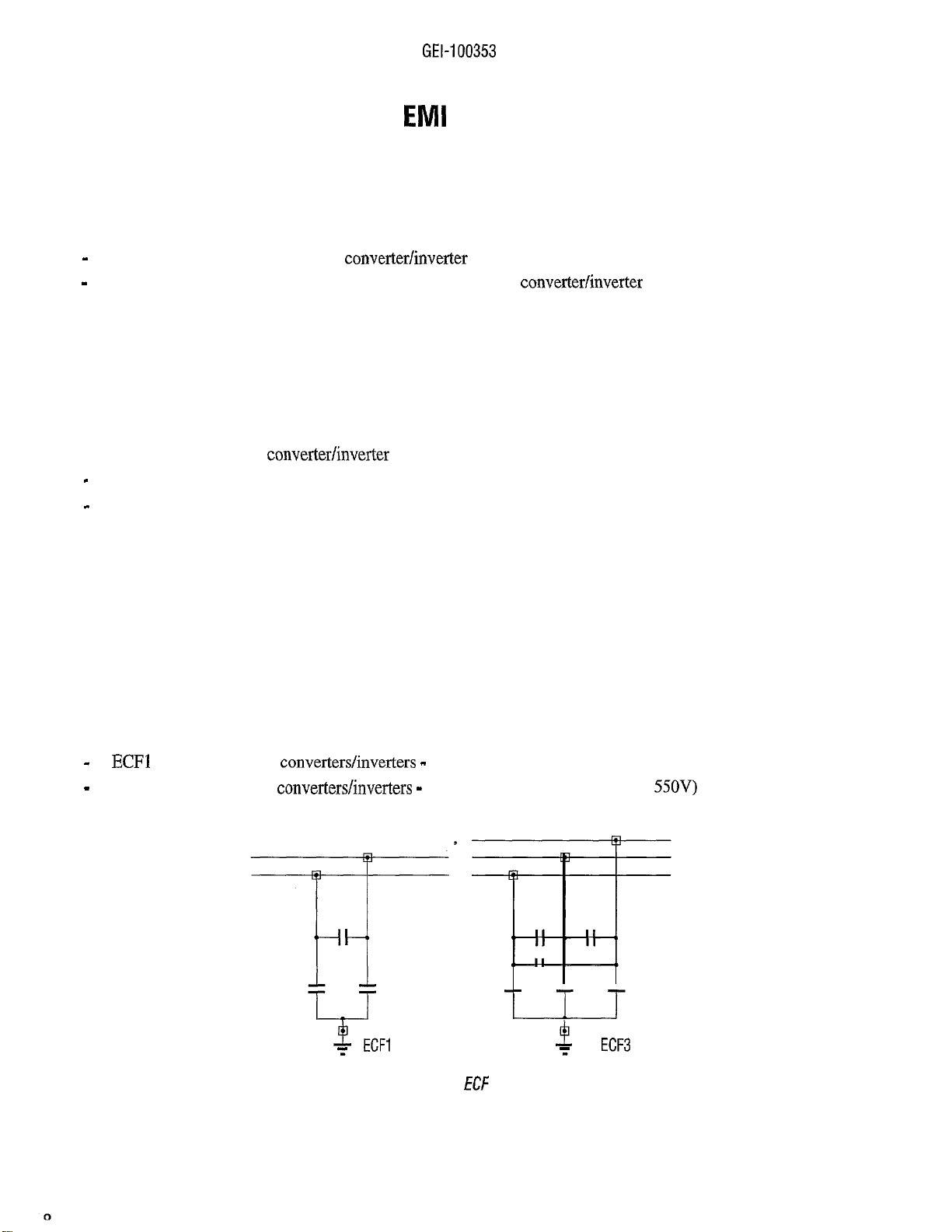
ECF series for the applications of
FN, Compact, Ranger or S-.... series for the applications of
plant (see table 1)
in the industrial plant (see table 1)
in residential and industrial
4.1 ECF FILTERS
ECF filters are needed for
motor cable length less then 20 m for 3015 device size and higher
motor cable length less then 100 m for device size up to 3011.
Applications that require long motor cable length (greater than 20 m) or residential installation environment,
will be satisfied by the FN, Compact, Ranger or S-.... filters.
The EFC filters are parallel connected on the supply line of the device.
The some kind of filter can be used for both converter and inverter. For multi-drive applications, it is enough to
use only one filter, which should be connected to the incoming line before all mains chokes, sized for the total
power rating of all units fed.
ECF filters are connected before the main choke.
in the industrial plant, with:
ECF filters are available in two versions:
(for single-phases
ECF3 (for three-phases
Max AC mains voltage allowed: 440V)
Max. AC mains voltage allowed:
Figure 4.1: ECF filters
Page 9
EMC GUIDELINES
4.2
FILTERS (FN,
EMI-FN filters, are high attenuation filters for generic applications, which can cover also the
applications during particular environmental conditions (residential) or plant (motor cables very long associated
to high-sized inverters).
EMI-FN filters are series-wired on the supply line of the device (see further insertion diagrams), so they have to
be sized, according to the load current of the device.
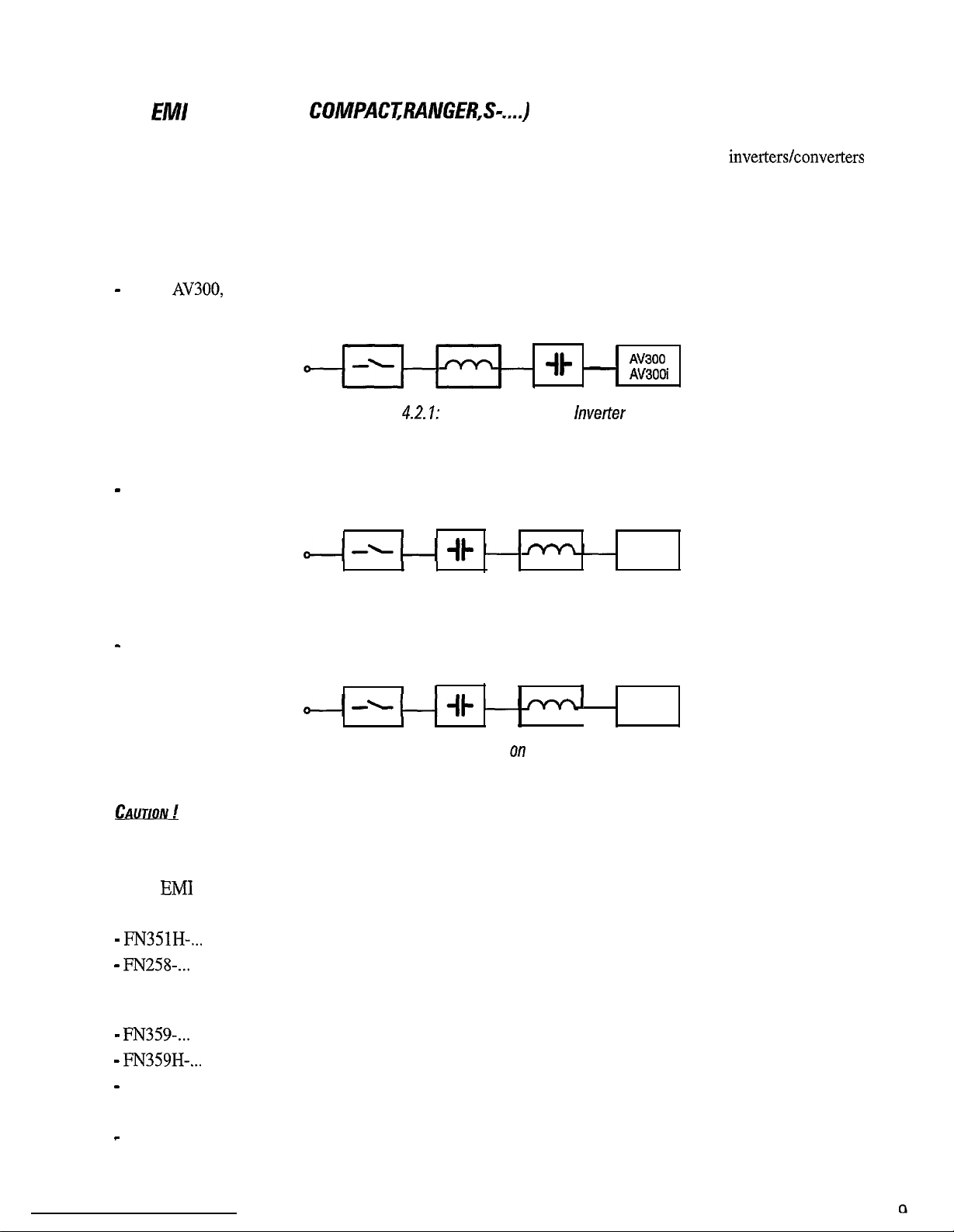
For
the filter should be connected between the mains choke and the drive
Mains supply
Choke Filter
Figure
For DV300, the choke should be connected between filter and drive
Mains supply
Filter connection on
Filter
Choke
DV300
Figure 4.2.2: Filter connection on Converter
For RS300, the choke should be connected between filter and drive
Mains supply
.
Figure 4.2.3: Filter connection
Filter Choke
Line Regen Converter
A wrong sequence during the installation of filters can damage the converter.
Filters
(FN, COMPACT, RANGER and S-....) are of following versions:
Max rated voltage 520V. Brick shaped. T amb = 104°F (40°C).
Book-shaped. Max. rated voltage 480V.
T amb = 104°F (40°C). With a derating of the rated current, it is possible the working
up to 122°F (50°C).
COMPACT-...
-RANGER-...
s-....
Max rated voltage 44OV. Brick shaped.
Max rated voltage 520V. Brick shaped.
Max rated voltage 440V. Book shaped.
Max rated voltage 520V. Brick shaped.
Max rated voltage 480V. Footprint shaped
RS300
Page 10

GEL100353
4.3 TABLES OF FILTERS SELECT/ON
To select a suitable filter, one has to take into account following:
kind of device (DV-300, AV-300,
size of the device;
motor cables length (important only for inverters);
class of the limits of EN5501 1 (A or B).
(overlaod are already factored in)
With the requirements above consult table 1, to pick which kind of filter to use.
ECF3: type ECF, three-phase version
: type ECF, single-phase version
The ECF filters don’t need further specifications, while FN, COMPACT and RANGER filters have to be selected
according to the size of the device (see tables
3 and 4).
Drive EN 55011 Motor cable length Filter
ECF3
Class A No limitation
DV-300
Class B No limitation
AV-300
Class A
Class B No limitation
Class A
For sizes
For sizes
3011: maximum length 100 m
3011: maximum length 20 m FN
No limitation
Class B
RS300 Class A No limitation
See tables 2/A, 2/B
See
s-....
See table 4
FN , COMPACT, RANGER
See table 5
Table I: Selection of the filters
3
in
Page 11

Drive Recommended filter
Mains voltage 230V
COMPACT-480-30
* Filters not mechanically interchangable
COMPACT-480-75
COMPACT-480-100
RANGER-520-280
RANGER-520-450
RANGER-520-450
RANGER-520-450
RANGER-520-600
RANGER-520-900
RANGER-520-900
RANGER-520-1200
400V
10%
07
07
34
35
35
07
99 *
99 *
99 *
99 *
99 *
*
99 *
Table
Drive Recommended filter
Filters for W-300 converters
Mains voltage 460V
RANGER-520-1200
COMPACT-520-30
COMPACT-520-42
COMPACT-520-75
COMPACT-520-130 FN351H-180
COMPACT-520-180
RANGER-520-280
RANGER-520-450
RANGER-520-450
RANGER-520-450
RANGER-520-600
RANGER-520-900
RANGER-520-900
RANGER-520-900
10%
33
33
34
99 *
99
99 *
99 *
99 *
99 *
99
99 *
35
36
36
* Filters not mechanically interchangable
Table
Filters for DV-300
converters
Page 12

Drive
Mains voltage 230V
Recommended filter
400V +I- 15%
I
Mains voltage 460V
10%
COMPACT-480-180
RANGER-520-280
RANGER-520-600 1
Filters not mechanically interchangable
Table 3:
Drive
Mains voltage 400V -15%
Table 4:
*
*
*
*
*
RANGER-SO-600
Filters for AV-300
Recommended filter
S-1321-24
Filters for
COMPACT-520-130
*
RANGER-520-280 FN359H-250/99
RANGER-520-280 FN359H-300/99
RANGER-520-600
480 V + 10%
*
*
*
*
Model
Mains voltage 230V
Mains filter limits according to EN55011
RANGER-520-180
RANGER-520-280
RANGER-520-450
RANGER-520-600
RANGER-520-900
RANGER-520-180
RANGER-520-280
RANGER-520-450
RANGER-520-600
I
RANGER-520-900
* Filters not mechanically interchangable
Table 5: Filters for RS-300 line regen converters
400V
15%
Class A
Mains voltage 460V
10%
I
Page 13
5. EMC COMPLIANT ELECTRICAL CABINET WIRING RULES
PANELS AND CABINETS
Mounting panel and cabinet (including the doors) have to be grounded, with a direct connection to the ground
bus, using star washers if possible.
REMOVAL OF THE PAINT FROM THE SUPPORT AREAS
The paint should be removed from the choke, mounting panel and chassis, support areas.
The anodized aluminium does not conduct.
GROUND
The inverters of AV-300 series are provided with two ground terminals: one must be connected to the ground
bus and the other to the filter.
OF THE
GROUND TERMINALS OF THE CONVERTER
DV-300 converters and RS300 line regen converters are provided only with one ground terminal which should
be connected directly to ground bus.
GROUND
The ground terminal of the choke must be connected to the
The ground terminal of the autotransformer, in case of RS300 converters must be connected to the ground bus.
OF THE CHOKE
SHIELD OF CABLES FOR ANALOG SIGNALS
The cables of analog signals must be shielded (each signal must be contained in the shield connected to the zero
volt terminal), the same is valid for the constant references (E.g..
converters the shield must be ground connected at 360” using the omega connectors available on the support
panel of the regulation board, in front of the terminals strip on the bar above the board.
Note: cable shields are grounded at one end only.
For AV-300 inverters and DV-300
GROUND CONNECTION OF THE ANALOG ZERO VOLT AND
The analog zero volt (power supply common) and the
like AV-300, DV-300 and RS300 series the following connection on the terminal strip are needed:
terminal 11 (analog 0 V) with terminal 10 (PE)
terminal 18
When many devices have,the zero volt (terminals 11 and 18) connected together, the PE connection must
be done with a 10 PF, 2 kV capacitor.
V reference potential) with terminal 20 (PE)
reference potential must be grounded. For devices
V REFERENCE POTENTIAL
Page 14
GROUND CONNECTION OF THE ANALOG ZERO VOLT FOR OPTIONAL TBO CARD
The common references of the TBO analog signals (terminal 2 and 4) must be connected to terminal 11 of the
drive regulation board.
For the RS300 device the common reference of the analog output signals (terminal 22) must be connected to
terminal 11 of the device regulation board.
The minimum distance between parallel signals and power cables (supply cables of the motor
inches). Possible crossings have to be made at 90”. In case of double cabinets (entry to the inside of the cabinet
on both sides with 2 different panels installed each other reverse side) it is advisable to have all signals cables
conveyed into ducts mounted on the inverter side (front) and to pass motor cables on the other side (back) trough
a hole made in the panel at the output of the inverter’s terminals.
In case of single cabinets, it is advisable to let the power cable run vertically, while those of signal horizontally,
keeping the maximum possible distance.
is 30cm (12
SHIELDING OF THE SUPPLY FOR AN AC MOTOR
The AC motors have to be supplied through a four pole shielded cable (three phases + green/yellow ground
wire), or through four unshielded cables, which are inserted inside a metal channel, consequently needing a
higher insulation (see relative safety standards). So, it is important that, further to the three phases, it has been a
direct connection (four cables) between the panel grounding and the motor and that the fourth cable had been
inserted in a shield.
GROUND CONNECTION TO BOTH SIDES OF THE CABLE SHIELD (AC MOTOR)
The shield of the supply cable of AC motors must be grounded on both sides in order to obtain a 360” contact,
that means the whole shield. This can be realized using suitable metallic EMC cables press grounded at 360” at
the input of the cabinet and of the motor’s terminal strip. If this connection is not possible, the shielded cables
should be brought inside the cabinet and connected with an omega connector (see figure) to the mounting panel.
The same must be done on the motor side: in case the connection at 360” on the motor’s terminal strip is not
possible, the shield must be grounded before entering into terminal strip, on the metal support of the motor,
using an omega connector (see figure). In case a metal duct has to be used, it should be both-sided grounded at
360” where possible.
PIGTAIL AVOIDING
While grounding the shielding of the cables, one has to adopt a 360” connection (E.g.: omega bus as in the table)
and the pigtail connection must be absolutely avoided. As pigtail here is meant the connection to earth of the
cable shield by means of a wire (or to use the same screen, roll it up and ground-connected).
SUPPLY CABLES OF THE DC MOTOR
The supply cables of DC motor do not need to be shielded.
DIRECT CONNECTION BETWEEN GROUND BUS AND MOTOR CHASSIS
Independently from any local ground-connection of the motor’s chassis, for safety reasons, it must always be
connected to the ground wire (yellow/green) coming from the panel ground bus.
Page 15

EMC GUIDELINES
MAX LENGTH OF
AC MOTOR’S CABLES
THE CABINET
From the grounding of the screen s&cabinet of the inverter terminal strip, the supply’s cables have to measure
at max. 5 meters (16.4 feet).
ENCODER CABLES
The encoder cable must be shielded and grounded only from the side of the inverter at 360”. The female connector
on the regulation board has been foreseen for that connection, therefore it is enough to have the cable shield
connected at 360” in the conductive case of the male connector.
In order to check that the shield is not connected on the motor side remove the encoder connector from the
inverter and verify with a tester the presence of a high impedance between the shield and the metal case of the
encoder or of the motor.
MOUNTING SEQUENCE FOR FN, COMPACT AND RANGER FILTERS WITH CONVERTER AND
LINE REGEN CONVERTER
In case of converters and line regen converetrs, these filters must be series-connected between the choke and the
AC line switch. The autotrasformer, in case of RS300 device, is always connected between the choke and regen
bridge input.
Do not connect, in any case, to the converter’s terminals.
GROUNDING OF THE FN, COMPACT AND RANGER FILTERS WITH CONVERTER AND LINE
REGEN CONVERTER
A grounding terminal’s filter must be connected directly to the panel bar, the other must be fixed to the mounting
panel as near as possible to the filter.
SEQUENCE FOR FN, COMPACT AND RANGER WITH INVERTER
In case of inverters, these filters have to be series-connected between the inverter and the AC mains. The
connection between the filter and inverter’s terminals must be done with a four pole cable, whose
30 cm. (12 inches). If that connection is longer, the cable must be shielded.
is
GROUNDING OF THE FN, COMPACT AND RANGER FILTERS WITH INVERTER
The yellow/green ground wire of the four poles cable, must be connected from one side directly to one of the two
inverter’s terminals, from the other to one of the two filters grounding terminals. The other grounding
terminals of the filter must be brought directly to the grounding bus of the cabinet.
MOUNTING SEQUENCE FOR ECF FILTERS
This kind of filter must be connected between the choke and the line switch, for whatever kind of devices
(inverters or converters).
Warning ! Never connect directly to the device’s terminals.
Page 16

00353
GROUNDING OF THE
The connection between device ECF and derivation point must have at maximum a length of 50
The grounding terminal of the ECF filter
FILTERS
inches).
must be directly connected to the ground bus of the cabinet. In case of
inverter, the same grounding terminal should be also connected to one of the two grounding’s terminals of the
inverter.
MOUNTING SEQUENCE OF THE FILTERS: SUMMARY TABLE
Device
LINE REGEN CONVERTER
MAINS-INDUCTANCE-FILTER-DEVICE
MAINS-FILTER-INDUCTANCE-DEVICE
FN
COMPACT -RANGER ECF
MAINS-FILTER-INDUCT~CE-DEVICE
Filtering connection using FN, COMPACT or RANGER filters:
Mains supply
Choke
Filter
Figure 5. I: lnverter
Mains supply
Filter Choke
Figure 5.2: Converter
Mains supply Filter Choke
Figure 5.3: line Regen Converter
DV300
. RS300
Page 17

Filtering connection using ECF
Filter
Mains supply
Shield
Choke
Figure 5.4: lnverter
DV300
Converter
Figure 5.5: OMEGA plug: grounding at
a shielded cable.
Page 18

RANGER
lnverter
\
Cabinet Mounting panel
cable
figure 5.6: Functional connection diagram of a
COMPACT or RANGER filter with
inverters
Page 19

AC Power Supply
AC
Mains
choke
filter
AC Mains
Ground
Bus
Figure 5.7: Functional connection diagram of a
with
Page 20

GEL100353
FN,COMPACT,
RANGER filter
Converter
Cabinet Mounting panel
Ground
RI
II I I
Encoder
Motor
Motor cable
terminals
Figure 5.8: Functional connection diagram of a
COMPACT or
filter with converters
Page 21

EMC GUIDELINES
FN,COMPACT,
RANGER filter
Line
reactor
II I l-f
Converter
\
Cabinet Mounting panel
Ground
Figure 5.9: Functional connection diagram of a FN, COMPACT or RANGER filter with line regen converters
Page 22

GEL100353
\
500 mm
ECF filter
Line
reactor
lnverter
Cabinet Mounting panel
Ground
Bus
Motor cable
terminals
J
Encoder cable
Motor
Figure 5.70: Functional connection diagram of a ECF filter with inverters
Page 23

EMC GUIDELINES
500
mm max
ECF filter
Line
reactor
Converter
Cabinet
Mounting panel
Ground
Bus
Encoder
J
Motor
\
Figure 5.
I: Functional connection diagram of a ECF filter witti converters
Page 24

Mains switch
AC
Omega connectors for connecting
the signal cable shield
cables canal
Omega connectors for connectin
the motor cable shield
Figure 5.12: Single side cabinet’s layout
Page 25

Mains switch AC contaciors
i
I
I
Figure 5.13: Double side cabinet’s layout
Page 26

GEI-100353
ATTACHMENT A
3
The possible validity fields of the
“CE
marking” summarizes the presumption of compliance with the
Directive ( 89
Essential Requirements of the EMC Directive, which is formulated
Clauses
numbers
refer to
European Commission
document “Guidelines on the Application
Validity
on the market.
Free
Complex component
sold “directly to
(clause 4.7 (4th E) and clause 4.7b]
consumer”
movement
EC Declaration of conformity required
The manufacturer of the PDS (or
based on.compliance with the EMC Directive
behaviour of the PDS (or
A
PDS
(or
of the Unrestricted Distribution
class
Additional EMC measures outside the item are described in an easy to
understand fashion and could actually be
The resulting
final product, by
guidelines.
only for professional assemblers
Complex componeut
only for professional
[clause 4.7
(2nd
A
PDS (or
and 3rd
and clause J.7a]
sold to be included as part of an
apparatus, system
or installation
competence to correctly install. Does not have intrinsic function for the end
user.
No EC Declaration of conformity
PDS
should comply with
The manufacturer
guidelines lhal will assist lhe manufacturer of the apparalus, system
compliance.
The resulting
installation, for which its OWI standards may apply.
of
PDS (or
behwiour is the responsibility of the manufacturer of the apparatus. sj’dcm,
336 ) applied to
in the
Description
is the responsibility of the assembler of the
the manufacturer’s recommendations and
EC
Declaration of
of
Council Directive
CE marking required
is responsible
under specified conditions.
by a layman.
have a
No CE marking
is
responsible
for
the EMC
of technical
Installation
[clause 4.61
One or more
Unrestricted -brought together at a
given
in or with apparatus,
or other components.
possibly of
Restricted or
Apparatus /system
[clause 4.4 and 4.5]
(A)
(or CDMBDM)
of the Unrestricted Distribution
class
in finished item(s)
Not intended to be placed on the market as a single functional unit.
Each
apparatus or system included is subject to the provisions of the EMC
Directive.
No EC Declaration of conformity
should comply with
EMC behariour is the
following an appropriate
EMC Directive apply regarding the neighbourhood of the installation.
Has an intrinsic function for the
No CE marking of the installation
of
plan). Essential protection requirements of
user and placed on the market as a
installer (e.g.
single commercial unit.
EC Declaration of conformity required
CE marking required
(for the apparatus or s:stcm)
Resulting EMC’ behaviour is the responsibility of the
manufacturer of the
apparatus or
Page 27

EMC GUIDELINES
ATTACHMENT B
Page 28

We bring good things to life.
GEI-100353 Rev. 0.1 (10/98)
GE Industrial Control Systems
Internet Address:
 Loading...