

Page 1

E4H-CE AND E8-CE SERIES
WATER PURIFICATION
MACHINES
3 m
3
/hr to 45 m3/hr
18,000 gpd to 288,000 gpd
Operation and Maintenance
Manual
Page 2

Page 3

INSTRUCTIONS FOR E4H-CE AND E8-CE
WATER PURIFICATION
OPERATION AND MAINTENANCE MANUAL
T
ABLE OF CONTENTS
Page
1.0 DESCRIPTION 1
1.1 Definitions 1
1.1.1 Permeate Rate 1
1.1.2 Concentrate Rate 1
1.1.3 Feed Rate 1
1.1.4 Reverse Osmosis 1
1.1.5 Membrane Elements 2
1.1.6 Clean-In-Place 2
1.1.7 Flow Control Center 2
1.1.8 Average Pressure 2
1.1.9 Concentration 2
1.1.10 Salt (Ionic) Passage 3
1.1.11 Recovery 3
1.1.12 Salt (Ionic) Rejection 3
1.2 Machine Nomenclature 5
1.3 Features 5
1.4 Specifications for E-CE Series Machines 7
1.4.1 Feed Water Specifications 8
1.4.2 Permeate Flow Rate 8
1.4.3 Concentrate Flow Rate 8
1.4.4 Pressure Range 8
1.4.5 Reverse Osmosis Membrane Element Rejection 9
2.0 INSTALLATION 10
2.1 Feed Water Requirements 10
2.2 Mounting 10
2.3 Plumbing 11
2.4 Power and Electrical Requirements 11
3.0 PREPARATION FOR START-UP 12
3.1 Pretreatment for Water Purification 12
3.2 Initial Start-Up 12
3.3 Daily Start-Up 16
Page 4

Page
4.0 MACHINE OPERATION AND MAINTENANCE 17
4.1 Daily Log Sheets 17
4.2 Pre-Filter Cartridge 17
4.3 Cleaning 17
4.4 Draining Machine for Shipment 19
4.5 Membrane Element Replacement 19
4.6 Membrane Element Removal 21
5.0 FIELD INSTALLED ACCESSORIES 22
5.1 Pretreatment Shutdown 22
5.2 Permeate Flush 22
5.3 Chemical Pump 24
5.4 Clean-In-Place Installation 24
6.0 TROUBLESHOOTING 25
7.0 FORMS 33
7.1 Return Goods Authorization (RGA) 33
7.2 Start-Up Data Sheet 34
7.3 Daily Log Sheet 35
8.0 WARRANTY/GUARANTEE 36
8.1 Warranty Terms 36
8.2 Warranty Commencement Date 36
8.3 Warranty Service 36
8.4 Voidability of Warranty 37
8.5 Limitations and Exclusions 37
Page 5

Page
LIST
OF
FIGURES
Figure Title
1.1 Normal Versus Cross Flow Filtration 1
1.2 Membrane Element With Interconnectors 2
1.3 Principles of Operation 3
LIST
OF T
ABLES
Figure T
itle
1.1 Flow Specifications for E-CE Reverse Osmosis Machines 7
1.2 Minimum/Maximum Boost Pressure 8
1.3 Membrane Element Specifications 9
2.4 Feed Water Requirements 10
2.5 Connections 11
Page 6
1.0 DESCRIPTION
E-CE Series Reverse Osmosis (RO) machines are durable pieces of equipment, which, with proper care, will last for many years. These instructions give operation and maintenance details vital
to the sustained performance of the machine. Please read completely before operating your
machine.
1.1 Definitions
The operating definitions provided below will help you further understand your machine
and this manual.
1.1.1 Permeate Rate (Product Water Rate) [Qp]
The Permeate Rate is the flow rate of purified water that passed through the membrane element and out of the membrane element in liter/min (Lpm), cubic
meters/hour (m
3
/h), gallons/min (gpm) or gallons/hour (gph). Specified permeate rates are based on a feed water temperature of 25°C (77°F). Permeate rate will
vary with temperature.
1.1.2 Concentrate Rate (Wastewater Rate) [Qc]
The Concentrate Rate is the flow of incoming water in Lpm or m
3
/h (gpm or gph).
1.1.3 Feed Rate [Qf]
The Feed Rate is the flow rate of incoming water in Lpm or m
3
/h (gpm or gph).
Feed water rate equals permeate plus concentrate rate.
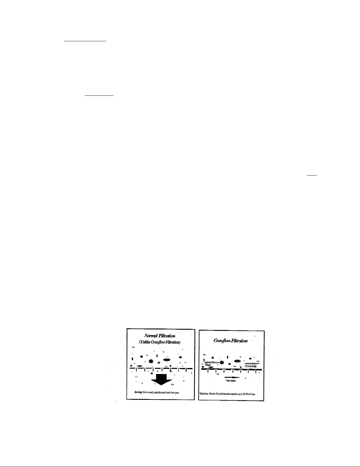
1.1.4 Reverse Osmosis
Reverse Osmosis (RO) is the separation of one component in a solution from
another component of a solution from another component by means of pressures
exerted on a semi-permeable membrane element. The feed solution is separated
into two streams, permeate and concentrate, and collected from both sides of the
membrane element.
Figure 1.1
Normal Versus Cross Flow Filtration
1
Page 7
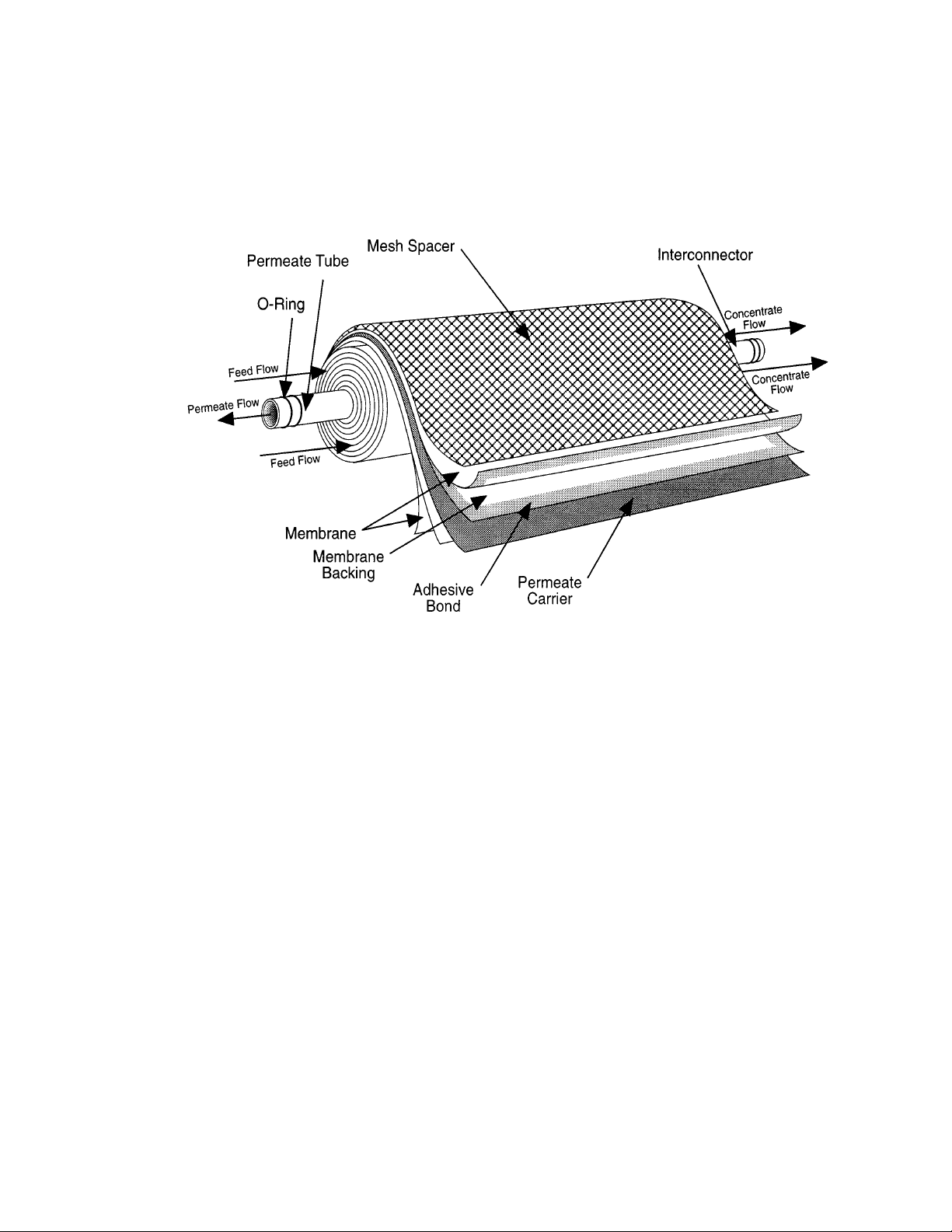
1.1.5 Membrane Elements
Membrane elements are interleaved layers of semi-permeable membrane, spacer,
and permeate carrier spiraled around a central permeate tube make up the membrane element.
Figure 1.2
Membrane Element with Interconnectors
1.1.6 Clean-In-Place
The abbreviation for Clean-In-Place is CIP.
1.1.7 Flow Control Center
The Flow Control Center features a concentrate flow control valve, a recycle flow
control valve, and a pressure gauge. It is located directly behind the control enclosure.
1.1.8 Average Pressure
P
AV G
(Average Pressure) = [(P
PRIMARY
+ P
FINAL
) ÷ 2]
1.1.9 Concentration
Concentration equals the Total Dissolved Solids (TDS) concentration of a solution
expressed as conductivity (µS/cm) or parts per million (ppm).
2
Page 8
C
f
= Feed Concentration
C
p
= Permeate Concentration
C
c
= Concentrate Concentration
C
avg
= Average Concentration in Machine
1.1.10 Salt (Ionic) Passage
Ionic Salt Passage equals the percent of dissolved salts passed through the membrane element or 100% minus rejection.
1.1.11 Recovery
Recovery equals permeate rate divided by feed rate and is expressed as a percentage. For example, 75% recovery means that out of a given feed rate, 75% is
produced as purified water (permeate).
1.1.12 Salt (Ionic) Rejection
Ionic Salt Rejection equals the percent of dissolved salt rejected by the membrane
element, calculated from an average concentration over the membrane element.
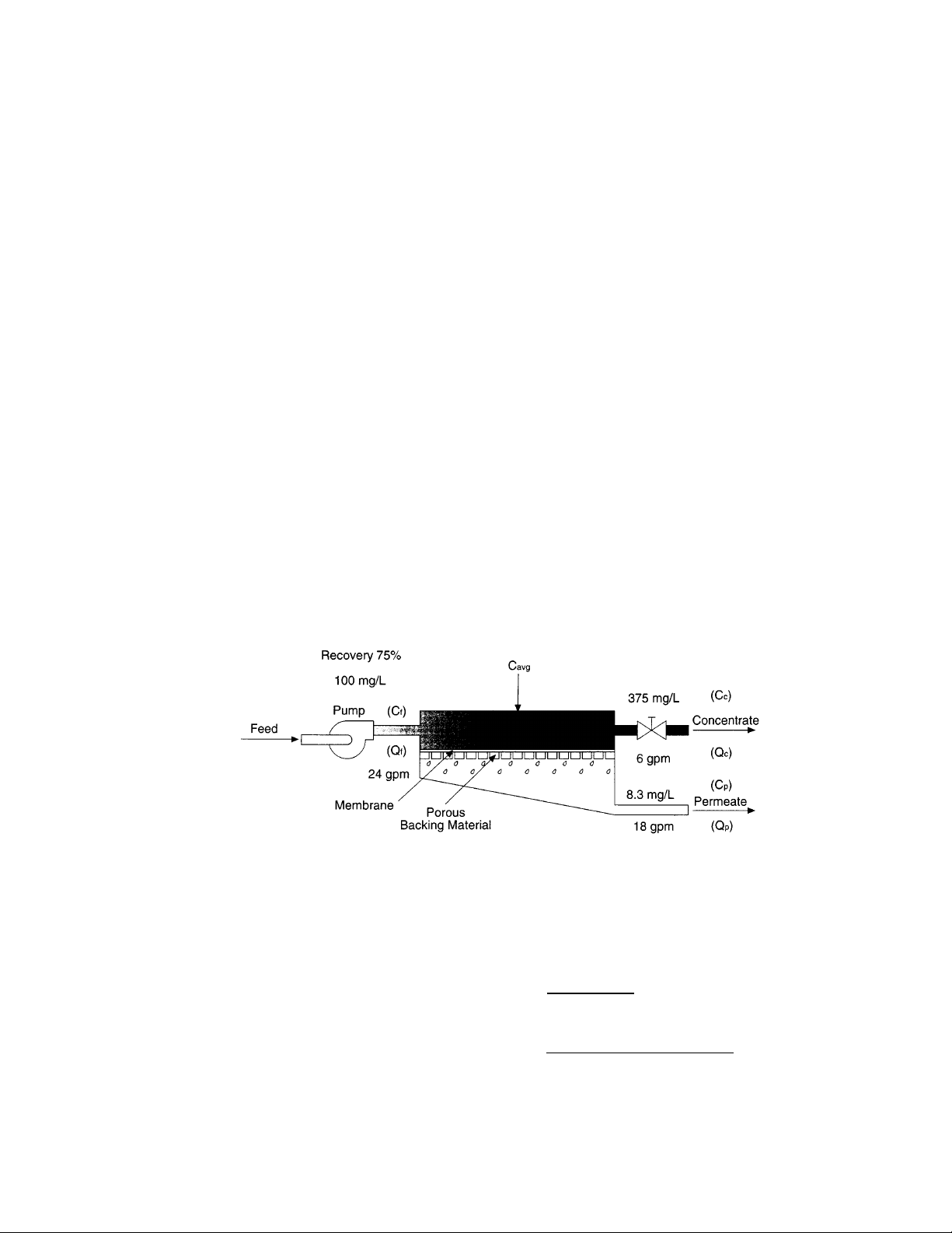
An example of how to calculate salt rejection and recovery is below:
Figure 1.3
Principles of Operation
Given the system case in Figure 1.3:
3
Average Concentration (C
avg
) = [(Cf) + (Cc)]
2
= [(100 mg/L) + (375 mg/L)]
2
= 237.5 mg/L
Page 9

4
Rejection = [(C
avg
) - (CP)] x 100
(C
avg
)
= [(237.5 mg/L) + (8.3 mg/L)] x 100
(237.5)
= 96.5%
Passage = (C
P
) x 100
(C
f
)
= (8.3 mg/L) x 100
(237.5)
= 3.5%
Recovery = (Q
P
) x 100
(Q
f
)
= (18 gpm) x 100
(24gpm)
= 75%
Page 10
1.2 Machine Nomenclature
E-CE Series water purification machines are numbered in such a way as to indicate the
permeate flow you can expect from the machine and other specifications:
Example: RE, E8-CE-9, 400, 5, 66 - 75
1.3 Features
E4H-CE and E8-CE water purification machines have all the features necessary for safe,
continuous production of high-purity water. This assumes properly pretreated feed water
with a TDS ≤ 2000 ppm and regular operator maintenance.
· Sixty-six (66) - 75% recovery (E8-CE) or 50 -75% recovery (E4H-CE). Adjust con-
centrate and recycle flows to obtain desired recovery.
· Epoxy-coated carbon steel frame.
· Three hundred fifty (350) square foot or 85 square foot (E4H-CE) membrane ele-
ments with stainless steel (SS) membrane element housings.
5
RO E8 - CE - 9 400 5 66 - 75
Machine Type Recovery Range
(Reverse Osmosis) 66 - 75% E8-CE
50 - 75% E4H-CE
Machine Series Hertz Operation
CE-E Series 5 = 50 Hertz
(E8: 8-inch housings/membrane elements)
(E4H: 4-inch housings/membrane elements)
CE Marked 400 VAC
3-Phase Starter
Rated Permeate Flow
[9 m
3
/hour at 25°C (77°F)]
Page 11

6
· Multi-stage centrifugal pump, SS construction (SS end castings and wetted parts,
Noryl* internals) on the 3 to 3 to 34m3/hr and AS (all Stainless Steel components)
on the 45m3/hr.
· Electrical package includes Programmable Logic Controller (PLC), IEC66 control
enclosure with a 24VDC control circuit, Siemens TP070 operator interface terminal,
and a Siemens S7-200 PLC.
· Twenty (20)-inch, 30-inch, or 40-in SS pre-filter housing, including 5-micron car-
tridge filters, GS05-20-XK, GX05-30-XK, GX05-40-XK for the E8-CE and 20-inch
PVC pre-filter housings, including 5-micron cartridge filters for the E4H-CE.
· Pre-filter, post-filter, primary, pump discharge, and final pressure gauges.
· Concentrate and permeate flow meters.
· Digital conductivity monitor, panel-mounted, for permeate quality monitoring with
high conductivity alarm.
· Gauges, valves, and rigid plumbing of SS or plastic.
·
Stainless Steel concentrate and recycle valves.
· External control capabilities (level control, pretreatment lockout).
· ALARMS included: low inlet pressure, high permeate pressure, high conductivity,
high pH, starter overload trip, and high temperature.
· Permeate purge capability.
·
High permeate pressure shutdown.
·
Low inlet pressure shutdown.
* Noryl is a trademark of General Electric Company.
Page 12

1.4 Specifications for E-CE Series Machines
The machine flow specifications listed, Table 1.1 below, are based on 25°C (77°F) and
2000 ppm NaCl.
Table 1.1
Flow Specifications for
Reverse Osmosis
E-CE Machines
7
MODEL
Recovery
Units
Permeate
Rate
Concentrate
Rate
(50-66%)
Concentrate
Rate
(75%)
Feed Rate
(50-66%)
Feed Rate
(75%)
Recycle
Rate
(55-66%)
Recycle
Rate
(75%)
E4H-CE-3
50-75%
LPM/GPM
47.4/12.5
47.4/12.5
15.8/4.2
94.7/25.0
63.1/16.7
15.1/4.0
46.6/12.3
E4H-CE-%
50-75%
LPM/GPM
78.9/20.9
78.9/20.9
26.3/7.0
157.8/41.7
105.2/27.8
0.0/0.0
46.2/12.2
E4H-CE-7
50-75%
LPM/GPM
126.3/33.4
126.3/33.4
42.1/11.1
252.5/66.7
168.4/44.5
0.0/0.0
81.5/21.5
E4H-CE-9
66-75%
LPM/GPM
151.4/40.0
75.7/20.0
50.5/13.3
227.1/60.0
201.9/53.3
68.1/18.0
93.4/24.7
E4H-CE-14
66-75%
LPM/GPM
227.1/60.0
113.6/30.0
75.7/20.0
340.7/90.0
302.8/80.0
107.3/45.0
208.2/55.0
E4H-CE-23
66-75%
LPM/GPM
378.5/100.0
189.3/50.0
126.2/33.3
567.8/150.0
504.7/133.3
56.8/15.0
119.9/31.7
Page 13

1.4.1 Feed Water Specifications
The feed water requirements listed in Table 1.1 must be met to ensure quality permeate and extended membrane element life.
1.4.2 Permeate Flow Rate
Stated in Table 1.1 and on the machine serial number label (assumes no permeate
back pressure, 2000 mg/L Total Dissolved Solids (TDS) maximum feed concentration, and rated temperature).
To estimate permeate output with back pressure, use the formula below.
Maximum permeate back pressure is 80 psig (5.5 bar).
(Specified Permeate) x [(Operating Pressure) - (Permeate Back pressure)]
(Operating Pressure)
1.4.3 Concentrate Flow Rate
Stated in Table 1.1 and factory-set as stated on the serial number label.
1.4.4 Pressure Range
The Pressure Ranges listed below (Table 2.1) are boost pressure:
Boost Pressure = [(Primary Pressure - (Post-Filter Pressure)].
Table 1.2
Minimum/Maximum (Min/Max)
Boost Pressure
8
MODEL
E4H-CE-3
E4H-CE-5
E4H-CE-7
E8-CE-9
E8-CE-14
E8-CE-23
PUMP MODEL
Tonkaflo, SS2823G-50
Tonkaflo, SS2823G-50
Tonkaflo, SS2823G-50
Tonkaflo, SS2823G-50
Tonkaflo, SS2823G-50
PRIMARY PRESSURE
RANGE bar (psi)
8.6 - 15.5 (125 - 225)
7.6 - 15.5 (110 - 225)
6.6 - 14.4 (100 - 210)
6.6 - 12.8 (95 - 185)
5.2 - 9.3 (75 - 135)
Page 14

1.4.5 Reverse Osmosis Membrane Element Rejection
E8-CE RO machines use Fiberglass Reinforced Plastic (FRP). E4H-CE RO
machines use tape wrapped membrane elements. For more information, refer to
the Spare Parts List (P/N 1233377).
Table 1.3
Membrane Element
Specifications
9
Specification
Outer Cover Material
Typical Ionic Rejection (TDS)
Nominal Permeate Flow Rate
[at 7.6 bar (110 psi)]
Typical Feed Water
Temperature Range
Maximum Temperature Range
Short-Term Cleaning
Temperature
pH Range
Chlorine Tolerance
Active Membrane Area
Average Molecular Weight
Cutoff*
E4H-CE
Tape
98.0 - 99.5%
8.3 m
3
/d (2200 gpd)
10° - 29°C (50° - 85°F)
0° - 40C (32° - 104°F)
< 43°C (110°F)
3.0 - 11.0
< 0.1 ppm
7.9 m
2
(85 ft2)
1500 MW*
E8-CE
FRP
98.0 - 99.5%
39.8 m
3
/d (10500 gpd)
10° - 29°C (50° - 85°F)
0° - 40°C (32° - 104°F)
< 43°C (110°F)
3.0 - 11.0
< 0.1 ppm
32.5 m
2
(350 ft2)
1500 MW*
* The Molecular Weight (MW) cutoff is based on the pore size of membrane elements and the
nature (size/shape) of the organic molecule.
Page 15

2.0 INSTALLATION
The following installation guidelines will help you install your new E-CE RO machine.
2.1 Feed Water Requirements
The following feed water requirements must be met before installing your new E-CE RO
machine to ensure quality permeate and extended membrane element life.
Table 2.4
Feed Water Requirements
2.2 Mounting
E-CE Series machines are equipped with a stand-alone frame, which supports the
machine. At least 114 cm (45-inches) of space should be allowed on each end of the
10
Temperature
Inlet Pressure
Chlorine (continuous feed)
Feed Water
Silt Density Index
(SDI)
Typical: 10 - 29°C (50° - 85°F)
Minimum: 2.1 barg (30 psig)
Maximum: 4.1 barg (60 psig)
0 ppm
For soft water [less than 1 grain per gallon
(gpg) or 17 mg/L hardness]
acceptable pH: 3.0 - 11.0
For unsoftened water (contact factory for
water analysis), acceptable pH: 5.0 - 6.0
For short-term (i.e., cleaning) acceptable
SDI range: 2 - 12
Less than or equal to 4 to minimize mem-
brane element fouling and extend cleaning
intervals. Refer to ASTM Standard
D4189
Page 16

membrane element housings for removal and loading of membrane elements. If 114 cm
(45-inches) are not available, the entire membrane element housing may need to be
removed for membrane element replacement.
2.3 Plumbing
The E4H-CE and E8-CE come with flanged connections installed on all isolation valves.
Table 2.5
Connections
2.4 Power and Electrical Requirements
WARNING: BEFORE OBTAINING ACCESS TO TERMINALS, ALL SUPPLY
CIRCUITS MUST BE DISCONNECTED.
IMPOR
TANT NOTE: Motor are dual rated. Factory installed starters and
wiring are for 400VAC (380VAC). Motor starter and
motor wiring must be replaced prior to converting to lower
voltage. Custom Factory Order (CFO) based motors can
be rated at other voltages. Check motor for rating.
The E4H-CE and E8-CE machines are supplied with a single source of incoming power.
This power can be 230, 380, 415, 460, or 575 VAC. Check tag on High Voltage Enclosure
to verify which voltage is required. The power for control is transformed down from the
three-phase power at the main disconnect to 230 single-phase and then down to 24 VDC.
For each model, the motor is wired at the factory to an overload protection motor starter,
which is controlled by the panel-mounted Operator Interface Terminal (OIT).
11
MACHINE
Model
Inlet
Concentrate
Permeate
E4H-CE
All Models
40 mm
25 mm
25 mm
E8-CE
9 - 14
50 mm
40 mm
50 mm
E8-CE
17 - 23
80 mm
40 mm
50 mm
E8-CE
28 - 45
100 mm
50 mm
80 mm
Page 17

3.0 PREPARATION AND START-UP
3.1 Pretreatment for Water Purification
All systems will operate most efficiently on filtered water with a pH of less than 6.5 and
a Silt Density Index (SDI) of 5 or below. If the machine is operated on higher pH water,
other forms of pretreatment may be necessary. A water analysis prior to start-up of the
machine is required. To minimize the chances of calcium carbonate, calcium sulfate, or
other salt precipitation on the membrane element, GE Osmonics evaluates each application and water condition and makes specific recommendations to assure continuity of the
membrane element warranty. Data from the water analysis is processed with a computer
program analysis to determine if potential problems may exist. If the machine is to be run
at a different location than was originally intended, a new water analysis is required for
warranty considerations and should be sent to GE Osmonics for review and recommendations for operation of the machine.
Before installing the machine, the feed water must be filtered to 5 microns.
Thin-layer composite (TLC) membrane element feed water must not contain the following chemicals or permanent loss of rejection and/or permeate flow may
result:
Free chlorine
Formalin (until after membrane element has run for 24 hours, thereafter, 0.5% formaldehyde may be Used as a biocide)
Iodine compounds
Quaternary germicides
Cationic surfactants
Detergents containing non-ionic surfactants
Cleaners not approved by GE Osmonics
CAUTION
: A water softener should not regenerate while the machine is running
unless safeguards are used to be sure the machine is operated on softened
water during regeneration.
NOTE
: To control the RO operation based on water softener regeneration cycle,
wire the softener to the Pretreatment Shutdown Control circuit, as
described in Field Installed Accessories.
3.2 Initial S
tart-Up
NOTE: If your machine has the membrane elements installed in the housing, pro-
ceed to Steps below. If your machine is provided with the membrane elements in shipping boxes, you must load the membrane elements in the
housings prior to starting the machine. For membrane element loading
instructions, go to Section 4.5 (Membrane Element Installation). Once
membrane element installation is complete, return to Step 1 (below) to
continue the start-up procedure.
12
Page 18

STEPS
1. Recheck the function and integrity of your pretreatment equipment. Ensure that
your water softener, activated carbon filters, and iron filters (where applicable)
have been leaked checked, back washed, and thoroughly rinsed for service before
starting up your RO unit.
2. Attach the feed water pipe to the inlet of the machine. The standard connection
fitting is a polyvinyl chloride (PVC) flanged connection. Refer to Table 2.5
(Connections) for connection sizes.
3. Check for leaks at all connection points.
4. Turn the feed water supply gradually ON and check for leaks in the inlet plumbing.
NOTE
: When the machine is OFF, there should never be flow through the
machine. Flow through the machine when it is OFF can ruin the membrane elements.
5. Attach discharge plumbing to permeate and concentrate outlet points and run the
tubing to the drain. The standard connection fitting is a polyvinyl chloride (PVC)
flanged connection. Refer to Table 2.5 (Connections).
6. The machine requires one high voltage power source. The motor electrical service must be field wired directly into the motor starter on the machine. Be sure
the power to the motor starter is de-energized by turning the disconnect on the
high voltage enclosure to the OFF position. The high voltage enclosure can only
be opened while in the OFF position. Bring your motor service to terminals
labeled “T” on the motor starter. Check the voltage label to ensure you have
brought the correct voltage to the starter.
IMPOR
TANT NOTE Motors are dual rated. Factory installed starters and
wiring are rated for 400VAC (380VAC). The motor
starter and motor wiring must be replaced prior to converting to a lower voltage.
7. Open your concentrate and recycle flow control valves (located behind the control enclosure).
The concentrate valve determines the amount of rejected water leaving the
machine and creates the operating pressure shown on the pressure gauge. The
recycle valve returns unused reject flow back into the inlet stream to the RO
pump. It is important to balance the operating pressure and the respective flows
of these valves to ensure that your machine is operating correctly.
13
Page 19

It is also important to understand the relationship of these two valves, the pressure
gauge, and your RO pump. The pump has a fixed amount of flow produced, and
the valves are the control devices to distribute this fixed flow amount. The pressure gauge is an indicator of applied membrane element pressure a the flows set
by the valves
8. Press the Fill Button on the OIT so it is in the ON position. Water should begin
to flow through the machine at this point, but the pump will not start. Allow the
machine to fill for ten (10) minutes.
9. As your machine is filling check for leaks and repair as needed.
10. Turn the ON/OFF switch, located on the High Voltage Enclosure, to the ON position.
11. Energize the power source to the motor starter. The pump should not operate at
this point.
12. Check the rotation of the high-pressure pump:
12a Press the RO button so it is in the ON position.
After the minimum inlet pressure [0.8 bar (11.6 psi)] is established and
maintained for six (6) seconds, the high-pressure pump will start.
12b When the high-pressure pump starts, immediately press the RO button so
it is in the OFF position.
The motor should rotate clockwise while looking at the motor end of the highpressure pump. If the motor is not rotating clockwise, change any two of the three
leads in the motor starter and recheck rotation.
W
ARNING: ALWAYS TURN POWER OFF TO CHANGE ANY
WIRING.
CAUTION
: Operation of the pump backward, even for a short time, can cause
damage to the pump.
13. Press the RO button so it is in the ON position. The high-pressure pump will
operate and the machine will begin to build pressure.
14. As the machine is operating, watch the primary and final pressure gauges on the
instrument panel. The machine is designed to operate at approximately 7.6 bar
(110 psi).
NOTE
: Do not allow the pressure to exceed the maximum boost pressure
(P
max
) specified for your machine model (Table 1.2). If the pressure
exceeds P
max
, open the concentrate and/or recycle control valves until
the pressure gauge shows P
max
or less.
14
Page 20

15. As the machine purges the air and fills with water, the pressure will gradually
increase. Water should flow through the permeate and concentrate piping, viewed
on the individual flow meters. If you do not see flow, turn the machine OFF and
return to Section 3.2 (Initial Start-Up).
16. Gradually adjust the concentrate flow control valve. As you adjust the valve,
watch the average pressure (P
avg
) and the your concentrate flow meter. Adjust the
valve until your concentrate flow meter displays the desired flow and does not
exceed P
max
. If P
max
is exceeded before the valve is completely closed, open the
recycle flow control valve one full turn, then continue to adjust the concentrate
flow valve.
17. With the concentrate flow control valve set to obtain the desired concentrate flow
and the pressure below P
max
, gradually adjust the recycle flow control valve until
P
avg
reaches 7.6 bar (110 psi). Readjust the concentrate and then the recycle
valves, if necessary.
18. Once the desired flow rate is achieved [7.6 bar (110 psi)] operating pressure, no
further valve adjustment is needed.
NOTE
: Permeate flow rates are dependent upon temperature and conditions at
your site. Contact your distributor if you have any questions.
The system is now operational.
19. Before putting the machine into final operation, continue to run the permeate and
concentrate streams to the drain for at least thirty (30) minutes
. This is done to
ensure that all the preservative have been removed from the membrane elements.
20. Connect the permeate line to the point-of-use of the permeate. Check for leaks
and ensure that you have no kinks in hoses or blockage of any plumbing on the
permeate and concentrate outlet lines.
21. Make any final adjustments for flow and pressure, according to Step 18, if needed.
22. Complete and create copies of the Start-Up Log Sheet (Section 7.2). A Daily Log
Sheet (Section 7.3), including general operating conditions (pressures, flow, concentrations, pH, and pretreatment conditions) and routine or special maintenance
(flushing or cleaning as needed) must be kept. GE Osmonics will require these
Log Sheets if a warranty question arises.
15
Page 21

3.3 Daily Start-Up
Check the machine to insure isolation valves are in the proper positions for operation.
To turn the RO ON, press the RO button so it is in the ON position. If the alarm light is
lit, push the “Alarm Reset” switch on the control enclosure and the alarm button on the
OIT. If the alarm light stays lit, check the RO for an alarm condition. Otherwise, the main
inlet valve will open, and the high-pressure pump will turn on. The high-pressure pump
will not start if there is insufficient inlet pressure [< 0.8 bar (< 12 psi)].
16
Page 22

4.0 MACHINE OPERATION AND MAINTENANCE
The operation and maintenance of a E-CE RO Series machine is relatively simple, but requires
regular data recording and routine preventative maintenance. It cannot be emphasized enough the
importance of filling out the Daily Log Sheet (Section 7.3) during each operating shift. A StartUp Data Sheet was completed at start-up (Section 7.2) containing pertinent facts on the operation
of your machine. These two records are invaluable in diagnosing the performance of the equipment or warranty issues, and must be kept for reference. If you have questions concerning the
operation of your machine or the method of data recording, contact the GE Osmonics Application
Engineering Department.
Three preventative maintenance procedures, which must be done on a regular basis, are as follows:
1. Change the pre-filter cartridges.
2. Flush the machine.
3. Clean the machine with approved Osmonics cleaners.
4.1 Daily Log Sheets
A Daily Log Sheet, which includes general operating conditions (pressures, flows, and
concentrations) and routine or special maintenance (pre-filter changes, flushing, cleaning,
etc.). must be kept. Copies of the Daily Log Sheet can be made from the Template
(Section 7.3). GE Osmonics will require copies of Daily Log Sheets if a warranty question arises.
4.2 Pre-filter Cartridge
A 5 micron pre-filter cartridge is factory installed to protect the membrane elements and
valves from particles, which may be in the feed water. To order replacements, see the
Spare Parts List (P/N 1233377).
Pre-filter cartridge must be replaced, at a minimum, once per week or after every 100
hours of operation, whichever occurs first. A pressure drop across the filter of 0.6 barg
(8.7 psig) or more during operation indicates that the pre-filters cartridge(s) need changing. Use only GE Osmonics approved filters rated for 5 microns or less. Do not attempt
to clean used filters. Install new replacements.
IMPOR
TANT NOTE: Failure to change the filter according to these requirements will
void machine warranty.
4.3 Cleaning
Cleaning the E-CE RO machines on a regular basis is vital. Over time, contaminants
build-up to form a layer on membrane element surfaces, reducing the permeate flow and
quality. If this build-up is not removed from the membrane element, it may cause permanent chemical damage and reduce membrane element life. A decrease in permeate
17
Page 23

flow and/or rejection of salts, or an increased pressure drop across the machine will indicate when cleaning is required. GE Osmonics recommends cleaning at least every month
to assure good membrane element performance and long membrane element life.
GE Osmonics offers a full line of chemical cleaners for specific cleaning needs. Refer to
the Spare Parts List (P/N 1233377).
To clean membrane elements:
STEPS
1. The E-CE RO machines do not include a Clean-In-Place (CIP) pump. A CIP
pump and tank need to be installed in order to complete the cleaning process.
GE Osmonics offers a stand-alone CIP system for the cleaning process. Refer to
the Spare Parts List (P/N 1233377).
2. With the E-CE RO machine running, open the CIP permeate valve. After this
valve has been opened, close the permeate service valve. Permeate water will
flow into the CIP tank. Open the CIP tank drain valve. Allow the water to run
through the CIP tank and the CIP drain valve for a few minutes to assure the tank
is rinsed thoroughly. Once the tank is rinsed, close the CIP tank drain valve. The
CIP tank will begin to fill with RO permeate. When the CIP tank has filled to the
indicated full line, press the RO button so it is in the OFF position.
3. With the machine OFF, close the service inlet and concentrate valves and open the
CIP inlet and concentrate valves. This will divert permeate and concentrate
streams to the cleaning container for recirculation. Insure that the pre-filter is
clean. GE Osmonics recommends that you replace the pre-filters prior to cleaning and again replace pre-filters after cleaning. Call GE Osmonics Customer
Support Center with questions concerning pre-filter replacement and cleaning.
4. Press the CIP button so it is in the ON position. The cleaning solution should be
recirculated for approximately fifteen (15) minutes or until the solution temperature reaches 38°C (100°F). DO NOT EXCEED 43°C (110°F). The membrane
elements can only handle temperatures in excess or 29°C (85°F) for short periods
of time. If heat rise occurs to quickly, larger volumes of cleaning solution or the
use of a heat exchanger will slow the temperature rise. Press the CIP button so it
is in the OFF position and allow the machine to soak for ten (10) minutes.
CAUTION
Do not leave the cleaning strength solution in the machine for a
period longer than one hour. The cleaning solution may damage
the membrane elements and the machine during an extended
period of contact.
5. To flush the detergent from the machine, close the CIP inlet valve, open the service inlet valve, and divert permeate and concentrate to the drain by opening the
CIP drain valve. Press the RO ON/OFF button so it is in the ON position to
18
Page 24

reestablish normal operation. Operate the machine as described in the flushing
section for at least one hour. The detergent is sufficiently flushed when the permeate conductivity is restored to its normal previous level. When conductivity is
back to normal, divert the permeate and concentrate back to service positions.
4.4 Draining Machine for Shipment
Prior to shipping or outside storage of a GE Osmonics E-CE RO machine, the system
should be cleaned with the appropriate cleaner, flushed with water, and protected from
biological attack with the appropriate solution. The membrane element housings and
pluming lines of the machine must be completely drained. Any water remaining in the
plumbing may freeze, causing damage to the plumbing, pump, membrane elements, etc.
The party shipping or storing the machine is responsible for any damage resulting from
freezing.
STEPS
1. Disconnect the inlet, concentrate, and permeate outlets.
2. Drain all water from the pre-filter cartridge housing.
3. Remove the tubing connections on the outlets of the membrane element housings.
4. Open the concentrate valve.
5. Open all sample/drain valves.
6. Remove drain plug from pump discharge plumbing.
7. Allow the machine to drain for a minimum of eight (8) hours or until the opened
ports quit dripping.
8. After draining is complete, reconnect all of the plumbing.
4.5 Membrane Element Replacement
CAUTION: The membrane element is packaged in a small amount of bactericide solu-
tion to prevent biological growth; provide adequate ventilation when handling. The membrane element must be kept moist at all times in order to
prevent possible damage to the membrane element material.
For machines with membrane elements not loaded at the factory:
STEPS
1. Remove the membrane element bag containing the membrane element from the
shipping tube.
19
Page 25

2. Cut the bag open as close as possible to the seal at the end of the bag, so that the
bag may be reused if necessary.
3. Remove the membrane element from the bag and remove the foam protectors
from each end of the membrane element.
4. Remove the parts from the parts container (if included) and inspect. Make sure
all parts are clean and free of dirt. Examine the O-rings, brine seal, and permeate
tube for nicks or cuts. Replace the O-rings or brine seal, if damaged. Set the
membrane element aside, in a clean space, and continue on to Step 5.
5. Remove the end caps from both ends of all membrane element housings on your
machine. This is done by removing the screws and retaining ring on each end cap
closure assembly.
6. Determine the direction of fluid flow in the membrane element housing. (Be cer-
tain to look at the “Direction of Flow” arrow on each membrane element housing;
they may be different within a given machine.)
7. Inspect the membrane element housing and clean as necessary to remove any con-
taminants, obstructions, etc.
8. Apply a small amount of O-ring lubricant to all O-rings on the end caps and the
brine seal on the membrane element.
9. Insert the downstream end of the membrane element in the upstream end of the
membrane element housing (i.e., load in the direction of flow; the brine seal is on
the end of the membrane element that goes in last).
10. Insert the membrane element in the membrane element housing with a smooth
and constant motion. When you reach the point where the brine seal is about to
enter the housing, gently turn the membrane element to ensure that the brine seal
enters the housing without coming out of the brine seal groove.
11. When all of your membrane elements are installed, close the membrane element
housing by reinstalling the end caps and clamps. It is preferred to install the bottom end cap first and tighten the clamp completely before installing the top end
cap.
12. Reinstall the end caps by gently twisting the end cap while pushing it on to the
permeate tube. Insure that you do not pinch or fatigue any O-rings while pushing
the end cap on. Push the end cap on until the outer diameter of the cap passes the
retaining ring groove. Install the retaining ring screws.
13. Reconnect any fittings that were removed when disassembling the membrane ele-
ment housings.
14. Return to Initial Start-Up (Section 3.2).
20
Page 26

4.6 Membrane Element Removal
As time progresses, the efficiency of the membrane element will be reduced. In general,
the salt rejection does not change much until two or three years after installation, when
operated on properly pretreated feed water and routine maintenance performed. The permeate flow rate will begin to decline slightly after one year of operation, but can be
extended with diligent flushing and cleaning of the machine. High pH feed water and/or
precipitation of hardness can cause premature loss in rejection and even flow rate. The
following procedure is to be followed to replace existing membrane elements in the
machine.
STEPS
1. Remove the end caps and clamps from all the membrane element housings.
2. Remove all the membrane elements from the membrane element housings in the
direction of flow (where possible). If necessary, a membrane element can be
removed against the direction of flow. Heavy-duty pliers or channel-lock pliers
may be necessary to pull the old membrane element out of the membrane element
housing.
3. To reinstall replacement membrane elements, see Section 4.5 (Membrane
Element Replacement).
NOTE
: Follow Membrane Element Specifications (Table 1.3).
NOTE: Do not allow the machine to freeze unless it is totally drained. It must
thaw a minimum of 24 hours before starting.
21
Page 27

5.0 FIELD INSTALLED ACCESSORIES
5.1 Pretreatment Shutdown
E-CE Series RO machines are equipped with Pretreatment Shutdown control capability.
Pretreatment Shutdown is the ON/OFF control of the RO via a signal from a remote
device. External Control can be used when Permeate Flush is not desired prior to RO
shutdown (Permeate Flush, Section 5.2). The Permeate Shutdown control could be
remote ON/OFF, level control, pretreatment lockout, and/or post-treatment lockout, etc.
Utilization of this feature requires a customer-wired control loop, wired to factory-supplied terminals. This procedure is as follows:
W
ARNING: BEFORE OBTAINING ACCESS TO THE TERMINALS, ALL SUP-
PLY CIRCUITS MUST BE DISCONNECTED.
STEPS
1. Establish that the remote device(s) have dry contacts available to provide the shutdown signal to the RO. Ensure that the normal mode of contact is such that it
opens when shutdown is desired.
2. With power removed from control enclosure, open enclosure.
3. Wire from the 24VDC source terminal #514 to the first remote device. Wire all
additional devices in series with the first. Wire the last remote device to terminal
#1006.
4. On the OIT, press the “Auto/Hand” button located under the RO button. Make
sure it is in the Auto position.
With multiple remote devices wired in series, as described above, an open contact
from any of the configured devices will activate the External Control Shutdown.
5.2 Permeate Flush
Permeate Flush is designed into the E-CE-RO machines to provide an integral means of
reducing the fouling potential of the stagnant concentrate in the RO during extended periods after automatic shutdown. The E-CE-RO machines are equipped with the necessary
plumbing and electrical controls to provide a 10-minute pure water (permeate) flush.
Activation of the purge cycle by remote device requires a customer-wired control loop to
factory supplied terminals. This procedure is provided later.
A second way to perform permeate purge is by manually pressing the Permeate Purge button on the OIT screen.
The purge cycle is activated by a shutdown signal received from an external device wired
to the RO. Upon activation of the Purge Cycle, the machine remains in run mode and the
permeate stream is redirected to the inlet of the machine. The feed water is diluted by an
amount proportional to the operating recovery of the machine. The net result, after con-
22
Page 28

centration of the diluted feed stream, at the operating recovery, is that the water in the
machine at shutdown will have total dissolved solids (TDS) concentrations approximately equal to the machine feed TDS level. The low TDS environment created reduces the
potential for membrane element fouling during the down period, extending membrane element life. The purge operates for a ten (10) minute period. During this period, no permeate is discharged from the machine and concentrate flows from the machine at the normal operating rate. When the cycle is complete, the RO pump will shut down. When the
request to restart is received, the RO will restart and operate as normal. If the restart signal is received during the Purge Cycle, the cycle will terminate and the RO will return to
normal operating mode.
Since this feature is designed to provide a low TDS environment during extended shutdown periods, the purge sequence will not activate for any factory-configured shutdown
event (i.e., ON/OFF switch, alarm shutdown, etc.). These shutdown events are assumed
to be typically short down periods. Also, activation of the purge cycle for these events
may be undesirable if immediate shutdown is required. The purge cycle will activate
when a shutdown request is made by an external component that is configured for purgeactivated RO shutdown.
Level control of a permeate storage tank is GE Osmonics’ standard external control device
which activates the purge shutdown. Any other remote device(s) can be used where permeate purge is desired prior to RO shutdown. Examples include: remote ON/OFF, posttreatment lockout, etc.
W
ARNING
: DO NOT CONFIGURE PRETREATMENT DEVICES FOR
PURGE-ACTIVATED SHUTDOWN. THE PURGE CYCLE
REQUIRES THE FEED WATER SUPPLIED BY THESE
DEVICES.
To establish the control loop for purge-activated shutdown, perform the following steps:
W
ARNING: BEFORE OBTAINING ACCESS TO TERMINALS, ALL SUPPLY
CIRCUITS MUST BE DISCONNECTED.
STEPS
1. Establish that the remote device(s) has dry contacts available to provide the shut-
down signal to the RO.
2. With power removed from the control enclosure, open enclosure.
3. Wire from the 24VDC source terminal #515 to the first remote device. Wire all
additional devices in series with the first. Wire from the last remote device to terminal #1007.
23
Page 29

4. Turn the AUTO/HAND Button on the Purge Button located on the OIT to the
“AUTO” position.
With multiple remote devices wired in series, as described above, an open contact
from any of the configured devices will activate the Permeate Purge Cycle.
5.3 Chemical Pump
GE Osmonics offers a stand-alone chemical pump and tank that can be used to control the
pH of the RO system. Refer to the Spare Parts List (P/N 1233377) for ordering information.
5.4 Clean-In-Place Installation
GE Osmonics has installed a flange connection in the inlet line of the E-CE RO machines.
Refer to Table 2.5 (Connections) for connection sizes. Valved Clean-In-Place (CIP) connections are provided on permeate and concentrate outlets to allow flow back to the cleaning tank. GE Osmonics offers a stand alone CIP system, refer to the Spare Parts List
(P/N 1233377).
24
Page 30

6.0 TROUBLESHOOTING
This troubleshooting guide can assist you in identifying common operating problems you may
experience with your machine. The operator can easily correct many of these problems, however, for those that persist or are not understood you should contact the GE Osmonics Customer
Support Center. Have the following information available when calling the Customer Support
Center:
1. Machine installation date
2. Model number
3. Serial number
4. Detailed description of problem
SYMPTOM
Low operating pressure
POSSIBLE CAUSES
Insufficient feed water pressure
flow
Clogged pre-filter
High flow rates
Dirty or fouled membrane
elements
Solenoid valve not opening
Pump rotating backwards
(three-phase power only)
REMEDIES
Open the feed pressure, open
the feed water valve, and
check for restrictions.
Replace pre-filter cartridge.
Close the concentrate valve,
check the permeate and con-
centrate flow rates and adjust
if necessary. Excessive per-
meate flow may indicate a
damage O-ring.
Flush and clean the membrane
elements.
Clean or replace the solenoid
valve.
Switch any two three-phase
leads to the motor starter.
25
TROUBLESHOOTING
Page 31

26
TROUBLESHOOTING
SYMPTOM
Low operating pressure
(continued)
Low permeate flow rate
POSSIBLE CAUSES
Insufficient electrical power
Pump not operating correctly
Low operating pressure
Dirty or fouled membrane
elements
Operating on cold water less
than 13°C (55°F)
Membrane elements installed
backward or damaged concen-
trate seal
Flow meter inaccurate
REMEDIES
Check the fuses or circuit
breakers; measure the voltage.
See Tonkaflo pump instruc-
tions.
See possible causes for low
pressure.
Flush and clean the
membrane elements.
Install a hot/cold feed water
tempering valve if more per-
meate flow is needed.
Operate with a feed water
temperature of 22° - 25°C
(72° -77°F).
Install membrane elements in
the direction of fluid flow.
Flush and clean the machine
immediately
. Membrane ele-
ments with damaged seals
should be cleaned and may be
returned for repair.
Check the flow rate manually
with a stopwatch and calibrat-
ed container.
Page 32

27
TROUBLESHOOTING
SYMPTOM
Low permeate flow rate
(continued)
Low concentrate flow rate,
normal or higher than normal
pressure
POSSIBLE CAUSES
Operating on cold water less
than 13°C (55°F)
Membrane elements installed
backward or damaged concen-
trate seal
Concentrate valve plugged
Concentrate outline line
restricted
Flow meter inaccurate
Dirty concentrate valve
REMEDIES
Install a hot/cold feed water
tempering valve if more per-
meate flow is needed.
Operate with a feed water
temperature of 22° - 25°C
(72° -77°F).
Install membrane elements in
the direction of fluid flow.
Flush and clean the machine
immediately
. Membrane ele-
ments with damaged seals
should be cleaned and may be
returned for repair.
Remove the concentrate valve
and/or disassemble the
plumbing. Clean the valve.
Examine the concentrate line
for obstructions or kinks,
repair or replace the tubing.
Check the flow rate manually
with a stopwatch and calibrat-
ed container.
Disassemble and clean the
plumbing to the valve.
Page 33

SYMPTOM
High operating pressure
Water flowing when
machine is turned OFF
Declining rejection (high
permeate conductivity)
POSSIBLE CAUSES
Recycle or concentrate valve
plugged
Inaccurate pressure gauge
Restricted flow after pump
outlet
Telescoped membrane ele-
ment covering membrane ele-
ment housing outlet port
Inlet solenoid valve not clos-
ing or seating properly
Severely fouled or dirty
membrane elements
Dirty or fouled membrane
elements
REMEDIES
Disassemble the plumbing
to the recycle valve and
remove foreign particles.
Check the concentrate
valve stem.
Replace or calibrate the
gauge as required.
Check for blockage of the
concentrate flow at the
inlets and outlets of the
membrane element
housings.
Ensure that the anti-telescoping device (ATD) is
located properly on the
membrane elements.
Clean or replace the valve.
Clean the membrane ele-
ments with detergent
immediately
. Water must
not pass through the inlet
when the machine is OFF.
Flush and clean the mem-
brane elements.
28
TROUBLESHOOTING
Page 34

29
TROUBLESHOOTING
SYMPTOM
Declining rejection (high
permeate conductivity)
(continued)
Machine not operating
POSSIBLE CAUSES
O-ring seal broken or dam-
aged
Change in incoming water
quality
Inaccurate conductivity moni-
tor or fouled probe
Pressurized storage switch or
float switch has cut power to
machine
External control or permeate
purge control contacts have
shut machine down
REMEDIES
Replace O-ring, check the
sealing surfaces on the
O-ring groove, intercon-
nectors and end caps.
Replace damaged parts.
Open the concentrate valve
and flush. Test the water
for pH, hardness, TDS, and
iron content. A water
analysis should be sent to
GE Osmonics for review.
Calibrate the monitor with
a DS standard solution or
check the readings with
another conductivity meter.
Replace or clean the probe.
Check the connections
between the probe and
monitor.
Check the permeate back
pressure or position of float
in the storage tank.
Check for proper orienta-
tion of control contacts.
Restart machine manually
or wait for automatic start-
up.
Page 35

30
TROUBLESHOOTING
SYMPTOM
Machine not operating
(continued)
Electrical machine shut
down
POSSIBLE CAUSES
Thermal overload in motor
has tripped
No power to machine
Motor and/or pump not oper-
ating properly
Alarm condition has turned
OFF machine
Alarm condition has turned
OFF machine
External control or permeate
purge control contacts have
been shut machine down
REMEDIES
Allow the machine to cool:
check the feed water supply
and/or amp draw to the
motor.
Check the fuses or circuit
breakers, measure the
voltage.
See Tonkaflo pump instruc-
tions. Contact GE
Osmonics for possible repair
or replacement.
Check for minimum inlet
pressure and push alarm
reset switch.
Restart the machine by
pushing the alarm bypass.
Check for possible alarm
conditions: inlet pressure or
motor starter overload.
Check for proper orientation
of control contacts. Restart
machine manually or wait
for automatic start-up.
Page 36

TROUBLESHOOTING
SYMPTOM
Electrical machine shut
down
(continued)
Conductivity drifts or
changes after calibration
Display is blank
pH reading is off by more
than 1pH unit
POSSIBLE CAUSES
Motor starter overloaded,
heater tripped.
Calibration may have been
done before the reading stabi-
lized
The stable line may contain
electrical noise
Turbine meter not spinning
Monitor not powered
Probe calibrated using span or
the pH probe is bad
REMEDIES
Turn the switch OFF; let the
heater(s) cool.
When calibrating, wait at
least 15 seconds to 1-1/2
minutes for reading to stabi-
lize.
To reduce electrical noise,
use grounded metal fittings
on the inlet and outlet of
the monitor plumbing.
Check meter for spin.
Open the front panel.
Look at the yellow LEDs
on the rear power board.
Are they ON? If yes, check
ribbon cable. Is it properly
seated? If no, does the unit
have power?
Re-initialize calibration.
Recalibrate using zero
only. Replace pH sensor.
31
Page 37

TROUBLESHOOTING
32
SYMPTOM
Chemical pump will not
feed chemical
Chemical pump feed
reverse of what you expect-
ed
POSSIBLE CAUSES
Pumping may be affected by
other software variables
Relay set point not properly
configured
REMEDIES
Is the relay turned ON or
OFF? Is the CIP input
activated? You must have
permeate or concentrate
flow for a relay configured
as a set point to function
and trigger the pump.
Determine whether you
need the relay configured
for direct or reverse set
point feed.
Page 38

7.0 FORMS
7.1 RETURN GOODS AUTHORIZATION (RGA)
If you wish to return goods for repair, warranty evaluation and/or credit, please have your
original sales order or invoice available when you call GE Osmonics. Call GE Osmonics
at (800) 848 - 1750 and ask to speak with Customer Service. A GE Osmonics Customer
Service representative will provide instructions and a return goods authorization number,
which needs to be clearly written on the outside of the box used to ship your materials.
All equipment must be shipped to GE Osmonics with the freight prepaid by the customer.
Call our Customer Service Center with any questions or issues concerning freight claims
and a representative will discuss your situation.
All materials to be returned must be rendered into a non-hazardous condition prior to shipping.
33
Page 39

34
E-SERIES
START-UP DATA SHEET
Customer:
Model Number:
Serial Number:
Date:
Tested By
Units (Circle One) Data Data Remarks
Permeate Rate
Total Flow Rate
Pre-Filter Pressure
Post-Filter Pressure
Primary Pressure
Final Pressure
Feed TDS
Concentrate TDS
Avg TDS
Permeate TDS (manual)
Permeate TDS (meter uS)
% Passage
(Perm TDS/Avg TDS)
Chlorine in Concentrate
Low Pressure Pressure
Switch Setting
7.2 Start-Up Data Sheet
Page 40

35
7.3 Daily Log Sheet
NAME OF COMPANY
NOTE: Please record all calibrations of instruments
or other occurrences related to this system.
This is a template. Make copies as needed.
*Symbols: Q - Flow Rate; C - Conductivity
Reference the Troubleshooting Guide in your Instruction Manual
where trends or differences are noted.
DATE AND TIME
PRE-FILTER PRESS (psi or bar)
POST-FILTER PRESS (psi or bar)
PRIMARY PRESS (psi or bar)
FINAL PRESS (psi or bar)
TEMP (ºF or ºC)
PERM FLOW (gpm or m
3
/h) Q
p
CONC FLOW (gpm or m
3
/h) Q
c
RECOVERY: Q
p
/ (Q
p
+ Q
c
)
FEED COND (mS) C
f
CONC COND (mS) C
c
AVG COND (mS) (C
f
+ C
c
) / 2
PERM COND (mS) C
p
FILTER CHANGE (
√√
)& TYPE
CLEAN (
√√
)
FEED CHLORINE (ppm)
FEEDWATER HARDNESS (gpg or ppm)
OPERATOR’S INITIALS
MACHINE MODEL NO.:
SERIAL NO.:
E-SERIES DAILY LOG SHEET
NOMENCLATURE
PRESS = PRESSURE
CONC = CONCENTRATE (BLOW-BY) Q
c
PERM = PERMEATE (PURE WATER) Q
p
RESIST = RESISTANCE
TEMP = TEMPERATURE
RECY = RECYCLE
COND = CONDUCTIVITY
PERIOD OF THIS SHEET TO
© Copyright 2003, GE Osmonics, Inc.
Printed in USA, P/N Rev. A
Page 41

8.0 WARRANTY
8.1 Warranty Terms
Subject to the terms and conditions set forth hereinafter, Seller (GE Osmonics, Inc. or any
of its authorized subsidiaries) warrants to the original purchaser (hereafter the “Buyer”)
that the products manufactured by Seller are free from defects in material and in workmanship for twelve (12) months from the Warranty Commencement Date (as defined
below) only when used strictly in accordance with the applicable operating instructions
and within the range of the operating conditions specified by Seller for each such product.
This Warranty does not extent to equipment or components manufactured by others into
which a Seller product has been incorporated or to equipment or components which have
been incorporated into a Seller product but, if allowable, Seller hereby assigns, without
warranty, to the Buyer its interest, if any, under any warranty made by the manufacturer
of such equipment or component. This Warranty does not cover disposable items such as
fuses, lamps, filters, cartridges, or other such disposable items, which must be replaced
periodically under the normal and foreseeable operating conditions of the goods warranted hereby.
8.2 W
arranty Commencement Date
The Warranty Commencement Date for each Seller product shall be the later of the date
of: (1) receipt by the Buyer, or (2) the date of installation at the Buyer’s premises provided that such installation must occur within three (3) months of shipment from the Seller’s
manufacturing facility in Minnetonka, Minnesota. In no event shall the Warranty
Commencement Date exceed three (3) months from the shipment from the Seller’s manufacturing facility. The Buyer shall provide proof of purchase in order to exercise rights
granted under this Warranty. If requested by Osmonics, the Buyer must also provide proof
of the installation date. Proof of installation shall be returned by Buyer to Seller within
thirty (30) days after installation by virtue of supplying a Warranty Validation Card supplied with each Seller product fully completed and signed in ink by Buyer and the authorized installer of the product.
8.3 W
arranty Service
SELLER’S OBLIGATION UNDER THIS WARRANTY IS LIMITED TO REPAIR OR
REPLACEMENT (AT SELLER’S SOLE OPTION) OF ANY PRODUCT, OR COMPONENT THEREOF, PROVED TO BE DEFECTIVE IN MATERIAL OR WORKMANSHIP WITHIN THE COVERED WARRANTY PERIOD. The Buyer. at the Buyer’s risk
and expense, shall be responsible for returning such product or component, upon obtaining a Return Goods Authorization (RGA) number from the Seller, freight prepaid, and in
conformance with any special packaging and shipping instructions set forth on the operation documentation or RGA instructions, or as otherwise reasonably required, to the
Seller’s address set forth below, together with (1) RGA number issued by Seller at Buyer’s
request; (2) proof of purchase and, if necessary, proof of installation date; (3) a description of the suspected defects; (4) the serial number of the Seller product alleged to be
defective; and (5) a description of the type of water pretreatment equipment which has
been utilized in connection with the product, if any. Seller shall, in Seller’s reasonable
36
Page 42

discretion, be the sole judge of whether a returned product or component is defective in
material or workmanship. Required or replaced products or components shall be returned
freight. In genuine emergency situation, Seller will (at Seller’s sole option) forward
replacement parts to Buyer without waiting for authorized return of the questionable
part(s). In such cases, Buyer will issue a purchase order or other payment guarantee prior
to shipment. If the returned part is found to have been misused or abused, the defective
part is not received by Seller within thirty (30) days, the Buyer will be invoiced for
replacement part(s) provided. This Warranty does not cover or include labor and/or travel to the Buyer’s premise or location or any other location. Charges will be made for the
usual and customary Seller costs and associated expenses incurred by Seller in providing
Warranty Service at any location other than Seller’s factory at the address set forth below,
and Seller reserves the right to precondition such travel to Buyer’s premises upon prepayment of Seller’s anticipated costs of attending such premises.
8.4 V
oidability of Warranty
This Warranty shall be void and unenforceable as to any Seller product which has been
damaged by accident, mishandling, abuse or has been repaired, modified, altered, disassembled or otherwise tampered with by anyone other than Seller or an authorized Seller
service representative; or, if any replacement parts are not authorized by Seller have been
used, or, the product has not been installed, operated and maintained in strict accordance
and adherence with the operating documentation and manuals for such product. Any
express warranty, or similar representation of performance set forth in the operation documentation for a reverse osmosis or ultrafiltration membrane incorporated into a Seller
product shall be void and unenforceable unless the feed water requirements set forth in the
operating documentation for such product are unequivocally and strictly adhered to.
8.5 Limitations and Exclusions
THIS WARRANTY AND REMEDIES DESCRIBED HEREIN AND HEREINABOVE
ARE EXCLUSIVE AND IN LIEU OF ANY AND ALL OTHER WARRANTY OR
REMEDIES, EXPRESSED OR IMPLIED, INCLUDING WITHOUT LIMITATION,
ANY IMPLIED WARRANTY OF MERCHANTABILITY OR FITNESS FOR A PARTICULAR PURPOSE. IN NO EVENT SHALL THE SELLER BE LIABLE FOR ANY
CONSEQUENTIAL, INCIDENTAL OR OTHER SIMILAR TYPES OF DAMAGES,
OR FOR DAMAGES FOR THE LOSS OF PRODUCTION OR PROFITS, OR INJURY
TO PERSON OR PROPERTY. NO PERSON HAS ANY AUTHORITY TO BIND
SELLER TO OTHER THAN WHAT IS SET FORTH ABOVE.
THIS WARRANTY GIVES THE BUYER SPECIFIC LEGAL RIGHTS AND THE
BUYER MAY ALSO HAVE OTHER RIGHTS WHICH VARY FROM JURISDICTION
TO JURISDICTION. THE PARTIES RECOGNIZE AND AGREE, THAT IN ALL
RESPECTS THE LAWS OF THE STATE OF MINNESOTA SHALL APPLY TO AND
SHALL GOVERN ANY INTERPRETATION OR LEGAL SIGNIFICANCE OF THIS
DOCUMENT.
37
Page 43

NO WARRANTY OR OTHER LIABILITY OF SELLER TO BUYER UNDER THIS
AGREEMENT OR OTHERWISE WILL IN ANY EVENT EXCEED THE COST OF
REPLACEMENT OF THE APPLICABLE SELLER PRODUCT, PART, OR ACCESSORY THAT IS SUBJECT TO ANY BREACH OF SELLER’S WARRANTY. SELLER
WILL NOT BE LIABLE FOR ANY DAMAGE TO ANY PROPERTY OF BUYER OR
TO BUYER’S CUSTOMERS FOR ANY CONSEQUENTIAL, INCIDENTAL, OR
ECONOMIC LOSS OR COMMERCIAL DAMAGE WHATSOEVER. REMEDIES
HEREIN PROVIDED ARE EXPRESSLY MADE THE SOLE AND EXCLUSIVE
REMEDIES FOR BREACH OF ANY WARRANTY OR OTHER OBLIGATION HEREUNDER EXPRESS OR IMPLIED OR FROM THE OPERATION OF LAW.
Any questions about this Warranty and all warranty service returns should be addressed
to:
GE OSMONICS, INC.
Minnetonka Operations
Attn: Customer Service Center
5951 Clearwater Drive
Minnetonka, MN 55343 USA
38
Page 44

Page 45

Corporate Headquarters
5951 Clearwater Drive
Minnetonka, MN
55343-8995
USA
(952) 933-2277 Phone
(952) 933-0141 Fax
Euro/Africa Operations
230 rue Robert Schuman
Z A des Uselles
F-77350 Le MØe sur Seine
FRANCE
+33 1 64 10 2000 Phone
+33 1 64 10 3747 Fax
Asia/Pacific Operations
1044/8 SOI 44/2
Sukhumvit Road Prakanong
Bangkok 10110
THAILAND
+66 2 38 14213 Phone
+66 2 39 18183 Fax
Call (952) 933-2277 for additional information, (800) 766-2599 i n the U.S., or visit w w w .osmonics.com
' Copyright 2002, Osmonics, Inc.
Printed in USA, P/N 1233379 Rev. A
Manufactured in the USA
 Loading...